

Page 1
USER’S GUIDE
Release 7.2
Cabletron Systems
(603) 332-9400 phone
(603) 337-3075 fax
[email protected]
C A B L E T R O N S Y S T E M S
Page 2

USER’S GUIDE
2 SmartSwitch Remote Access Module
NOTICE
You may post this document on a network server for public use as long as no
modifications are ma de to th e do cu ment.
Cabletron Systems reserves the right to make changes in specifications and other
information contained in this document without prior notice. The reader should in
all cases consult Cabletron Systems to determine whether any such changes have
been made.
The hardware, firmware, or software described in this manual is subject to change
without notice.
IN NO EVENT SHALL CABLETRON SYSTEMS BE LIABLE FOR ANY
INCIDENTAL, INDIRECT, SPECIAL, OR CONSEQUENTIAL DAMAGES
WHATSOEVER (INCLUDING BUT NOT LIMITED TO LOST PROFITS) ARISING
OUT OF OR RELATED TO THIS MANUAL OR THE INFORMATION
CONTAINED IN IT, EVEN IF CABLETRON SYSTEMS HAS BEEN ADVISED OF,
KNOWN, OR SHOULD HAVE KNOWN, THE POSSIBILITY OF SUCH
DAMAGES.
©Copyrigh t 1998 by Cablet ron Systems, Inc. All rights reserved.
Cabletron Systems, Inc.
P.O. Box 5005
Rochester, NH 03866-500 5
Order Number: 9032490
VIRU S D ISCLAIMER
Cabletron Systems has tested its software with current virus checking
technologies. H owev er, because no anti-vir us sy stem is 100% rel iable, we strongly
cauti on you to wr ite pro tect and th en verif y that th e Licen sed Sof tware, pr ior to
installing it, is virus-free with an anti-viru s system in which yo u have confi denc e.
Cabletron Systems makes no representations or warranties to the effect that the
Licensed Software is virus-free.
Copyright © July 1997, by Cabletron Systems, Inc. All rights reserved.
Only qualified personnel should perform installation
procedures.
!
CAUTION
Page 3

9W006 and 9W007 3
TRADEMARKS
Cabletron Systems, CyberSWITCH, MMAC-Plus, SmartSWITCH, SPECTRUM,
and SecureFast Virtual Remote Access Manager are trademarks of Cabletron
Systems, Inc.
All other product names m entioned in this manual are tradema rks or registered
trademarks of their re sp e ctive companies.
COPYRIGHTS
All of the code for this product is copyright ed by Cable tron System s , Inc.
© Copyright 1991-1997 Cabletron Systems, Inc. All rights reserved. Printed in the
United States of America .
Portio ns of the code for this p roduct are co pyrighted by the follow ing corpor ations:
Epilogue Technolo gy Co rporat io n
Copyright 1991-1993 by Epilogue Technology Corporation. All rights reserved.
Livingston Enterprises, Inc.
Copyright 1992 Livingston Enterprises, Inc.
Security Dynamics Technologies Inc.
Copyright 1995 by Security Dynamics Technologies Inc. All rights reserved.
Stac El e c tronics
Stac Electronics 1993, including one or more U.S. Patents No. 4701745, 5016009,
5126739 and 5146221 and other pending patents.
Telenetw orks
Copyright 1991, 92, 93 by Telene tworks. All rights reserved.
FCC NOTICE
This device complies with Part 15 of the FCC r ules. Operation is subject to the
following two conditions: (1) this de vice m a y no t caus e ha r mful interference, and
(2) this device must accept any int erference received, includ ing interference that
may caus e undesired op e ra ti on.
NOTE: This equipment has been tested and found to comply with the limits for a
Class A digital device, pursuant to Part 15 of the FCC rules. These limits are
designed to provide reasonable protection against harmful interference when the
equipment is operated in a commercial environment. This equipment uses,
generates, and can radiate radio frequency energy and if not installed in
accordance with the operator’s manual, may cause harmful interference to radio
communications. Operation of this equipment in a residential area is likely to cause
interference in which case the user will be required to correct the interference at his
own expense.
Page 4
USER’S GUIDE
4 SmartSwitch Remote Access Module
WARNING : Changes or modific ations made to this d evice wh ich ar e not exp ressly
approved by the party responsible for compliance could void the user’s authority
to operate the equipment.
DOC NOTICE
This digital apparatus do es not exceed the Class A limits for radio noise emissions
from digital apparatus set out in the Radio Interference Regulations of the
Canadian Department of Co mmunications.
Le présent appareil numérique n’émet pas de bruits radioélectriques dépassant les
limites applicables aux appareils numériques de la class A prescrites dans le
Règlement sur le brouillage radioélectrique édicté par le ministère des
Communicatio ns du Cana d a.
VCCI NOTICE
This is a Class 1 product based on the standard of the Voluntary Control Council
for Interference by Information Technology Equipment (VCCI). If th is equipment
is used in a domestic environment, radio disturbance may arise. When such
trouble occurs, the user may be re quired to take corrective actions.
CABLETRON SYSTEMS, INC. PROGRAM LICENSE AGREEMENT
IMPORTANT: Before utilizing this product, carefully read this License Agreement.
This document is an agreement between you, the end user, and Cabletron Systems,
Inc. ("Cabletron") that sets forth your rights and obligations with respect to the
Cabletron software program (the "Program") contained in this package. The
Progra m may be contai ned in fi rmware, ch ips or ot her media. BY UTILIZ ING THE
ENCLOSED PRODUCT, YOU ARE AGREEING TO BECOME BOUND BY THE
TERMS OF THIS AGREEMENT, WHICH INCLUDES THE LICENSE AND THE
LIMITATION OF WA RRANTY A ND DISCLAIMER O F LIABILITY. IF YOU DO
NOT AGREE TO THE TERMS OF THIS AGREEMENT, PROMPTLY RETURN
THE UNUSED PRODUCT TO THE PLACE OF PURCHASE FOR A FULL
REFUND.
Page 5

9W006 and 9W007 5
CONTENTS
Using this Guide 12
Documentation Set 12
Guide Conventions 13
SYSTEM OVERVIEW 14
The SmartSwitch Remote Access Module 15
The SmartSwitch Remote Acc e ss M odule Network 15
9W006 and 9W007 Functionality 16
Telco Interfaces 16
Digital Modem 17
Management 17
Additional Sof tware 18
Unique System Featur es 18
Interoperability Overv iew 20
Interoperability Protocols 20
Interoperability Devices 21
Security Overview 21
Network Interface Overview 22
System Compon e nts 23
Remote ISDN Devices 23
Switches Supported 24
Hardware Overvi ew 25
SmartSwitch Remote Access Module Hardware 25
Available Hardwa re Co nfigurations 25
Module Specifications 28
Module Interfaces 28
Module LEDs 28
SMB LED 29
Power LED 29
Ethe rnet 1 & 2 Ac ti vity L ED s 29
Module Ports an d Connectors 30
SmartSwitch 9000 Chassis Support 30
System Management Bus (SMB-1) 31
Software Overview 32
Overview 32
System software 32
System Files 32
Configuration Files 32
Operational Files 33
Page 6

USER’S GUIDE
6 SmartSwitch Remote Access Module
Configuration Overview 35
Overview 35
SFVRA Configuration Mana ger 36
Starting the SFVRA-CFG Application 36
CFGEDI T 37
Executing CFG EDIT 37
Saving CFGEDIT Changes 37
Dynamic Management 38
Executing Dynamic Management 38
Utility Dynamic Management Commands 38
Saving Dynamic Managem e n t Changes 39
SYSTEM INSTALLATION 40
Orderi n g PRI ISDN Servic e (US Only) 41
Hardware Installat ion 43
Overview 43
Installing the SmartSwitch Remote Access Module 43
Unpacking the SmartSwitch Remote Access Module 43
Install ation 44
Connecting the Module’s Cabling 44
Module to SmartSwitch 9000 Et hernet Cabling 45
Mod-Tap Adapter 45
Module to PRI Service Cabling 45
Resta r t in g the S m a r tS witch Remote Ac ce s s M o d ule 46
Accessing the SmartSwitch Remote Access Module 47
Overview 47
Accessing a New Module 47
Initial Assess Using a PC and a Termina l App lic ation 47
Initial Access Using Telnet 47
Establishing an Administration Session 48
Assigning the Module’s IP Address 48
Accessing th e Re lease Notes 49
Remote Access using Telnet 49
Upgrading System Software 50
Overview 50
Telnet Connection 5 0
Upgrading Software 50
Accessing th e Re lease Notes 51
TROUBLESHOOTING 52
System Verification 53
Overview 53
Verifying Hardware Resources are Operational 53
Verifying WAN Lines are Available for Use 54
Page 7

9W006 and 9W007 7
Verifying LAN Connection is Operational 55
Verifying Bridge is Initialized 55
Verifying IP Router is Initialized 56
Verifying a Dedicated Connection 56
Verifying Remote Device Connectivity 57
Verifying IP Routing Over Interfaces 57
Verifying IP Routing Over a LAN Interface 57
Verifying IP Routing Over a WAN Interface 58
Verifying IP Routing Over a WAN Remote LAN Interface 60
Verifying IP Routing Over a WAN UnNumbered Interface 61
Verifying IP RIP 62
Verifying IP RIP is Initialized 62
Verifying IP RIP Output Processing on a LAN Interface 62
Verifying I P RIP I nput Processi ng on a LAN Interface 64
Verifying IP RIP Output Processing on a WAN Interface 65
Verify IP RIP Inpu t Processing Operational on a WAN Interf ace 66
Verifying IPX Router is Initialized 66
Verifying IPX Routing is Operational 67
Verifying IPX Ro uting over a LA N Connection 67
Verifyi ng an IPX Re mote LAN Connection 68
Verifying I P X Rou ting over a WAN Connection 68
Verifying Triggered RIP/SAP 69
Verifying the AppleTalk Routing Feature 69
Verifying AppleTalk Routing is Initialized 69
Verifying AppleTalk Routing is Operational 70
Verifying AppleTalk Routing Operational over the LAN connection 71
Verifying AppleTalk Routing Operation over a WAN connection 71
Verifying SNMP is Operational 72
Verifying the Dial Out Feature 73
Verifying Compressio n is Op erational 7 3
Verifying Reserved Bandwidth is Operational 73
Verifying a Semipermanen t Conne cti on 74
Problem Diagnosis 75
Overview 75
WAN Adap ter 75
LAN Adapter 75
Bridge Initializa tion 76
IP Routing Initialization 76
WAN Line Availability 78
Dedicated Co nnections 80
Remote Device Connectivity 80
LAN Attach ment 82
IP Routing Over Interface Connections 82
IP Routing Over the LAN Interf ace Co nnec tion 8 2
IP Routing Over a WAN Interface Connection 84
IP Routing Over a WAN RLAN Interface Connection 86
IP Routing Over a WAN UnNumbered Interface Connection 87
Page 8

USER’S GUIDE
8 SmartSwitch Remote Access Module
IP RIP 88
IP RIP Initialization 88
IP RIP Output P rocessing on a LAN Interface 88
IP RIP Input Processing on a LAN Interface 90
IP RIP Output P rocessing on a WAN Interface 90
IP RIP Input Processing on a WAN Interface 91
IPX Routing 91
IPX Routing Initialization 91
IPX Routing ove r the LAN Connection 92
IPX Routing ove r the Remote LAN Connection 93
IPX Routing ove r the WAN Connection 95
Triggered RI P /SAP Start Up 95
Triggered RIP/SAP Operation 95
AppleTalk Routing 96
AppleTalk Routi ng Initialization 96
AppleTalk Routing Operational ov er the LAN connection 97
AppleTalk Routing Operational ov er the WAN connection 100
SNMP 101
Dial Out 105
Compression 107
System Messages 109
Overview 109
Informational Messages 109
Initialization Messages 110
Normal Operation Messages 110
Spanning Tree Messages 110
Warning Messages 110
Error Messages 110
System Message Summary 110
Trace Messages 168
Overview 168
Call Trace Messages 168
Call Trace Message Summary 169
PPP Packet Trace Messages 175
SYSTEM MAINTENANCE 178
Remote Management 179
Overview 179
SNMP 180
Installation and Configuration 180
Usage Instru ctions 181
Telnet 182
Installation and Configuration 183
Usage Instru ctions 183
WIN95 Dial-Up Networking 185
Setting up a New Number 185
Setting Up Server Type 185
Dialing Out 185
Page 9

9W006 and 9W007 9
TFTP 186
Installation and Configuration 186
Usage Instru ctions 187
Carbon Copy 188
Installation and Configuration 188
Changing CARBON COPY Configuration Parameters 188
CARBON COPY Configuration Parameters for Modem Usage 189
Usage Instru ctions 190
Establishing a Remote Administration Session 190
Terminating a Remot e Admi nistration Session 191
Performing a File Transfer Using CARBON COPY 192
Running without Carbon Copy 193
Remov in g Ca rb o n Co p y 19 3
Null Modem Connection 193
Adding Carbo n Copy 194
System Commands 195
Overview 195
Accessing Admin istration Services 195
Setti n g th e I P Ad d r e s s 1 96
Viewing Operational Inf orm ation 196
Viewing Throughput Information 200
Throughput Monitor Contents 201
Saving Operational Information 202
Clearing Opera tional Inf orm atio n 202
Terminat ing and Restarting the SmartSwi tch Remote Access Module 203
Setti n g the D ate and Ti me 203
Terminating Admin istration Sessions 204
AppleTalk Routing Commands 205
Bridge Commands 209
Call Control Co m ma nd s 210
Call Restriction Commands 213
Compression Information Commands 214
Digita l Modem Commands 214
IP Routing Commands 215
IPX Rou ting Commands 219
ISDN Usage Commands 221
LAN Commands 222
Packet Capture Commands 222
SNMP Co mma nds 225
Spanning Tree Comma nds 225
Spanning Tree Port Information 226
Spanning Tree Bridge Information 226
TCP Commands 228
Telnet Commands 228
Termina l Commands 231
TFTP Commands 232
Trace Commands 233
UDP Command s 2 3 4
WAN Comm an ds 234
Page 10

USER’S GUIDE
10 SmartSwitch Remote Access Module
System Statistics 236
Overview 236
Connectivity Statistics 236
Call Restriction Statistics 237
Call Statistics 237
Throughput Monitoring Statistics 237
AppleTalk Statisti cs 238
AppleTalk Protocol Statistics 238
AppleTalk Data Delivery Protocol (DDP) Statistics 238
AppleTalk Echo Protocol (AEP) Sta ti stics 239
AppleTalk Rou ting Table Maintenance Protocol (RTMP) Statistics 240
AppleTalk Zone Informati on Protocol (ZIP) Stati stics 240
AppleTalk Name Binding Protocol (NBP) Statistics 241
AppleTalk Transaction Protocol (ATP) Statistics 241
AppleTalk Port Statistics 242
Bridge Statistics 243
Compression St atistics 243
Compression Related Statistics 244
Decompressi on Related Statistics 244
Digital Modem Statistics 245
LAN Stati st ics 245
IP Statistics 245
IP Group Statistics 246
ICMP Group Statistics 247
IPX Statistics 249
IPX General Statistics 249
IPX Basic System Table Statistics 249
IPX Advanced System Table Stati stics 250
IPX RIP Statis tics 251
IPX Triggered RIP Statisti cs 251
IPX Route Statistics 252
IPX SAP Statistics 252
IPX Triggered SAP Statistics 253
IPX Service Statistics 253
RIP Statist ics 254
RIP Global Stati stics 254
RIP Interface Statistics 254
SNMP Statistics 255
TCP Statistics 257
TFTP Statistics 258
Statistics for Serve r or Rem o te initia ted TF TP Ac tiv ity 258
Statistics for Loca l or Clien t Initia ted TFTP Ac tiv ity 259
Statistics for all TFTP Activity 259
UDP Statistics 260
WAN L1P Statistics 260
PRI S/T (T1/E1) Interface Statistics 260
Layer 1 PRI Error Stat istics 261
Layer 1 General Stati stics 262
WAN Statistics 262
Page 11

9W006 and 9W007 11
Routine Maintena nce 26 4
Overview 264
Installing/Upgrading System Software 264
Configuration Backup and Rest ore 264
Obtaining System Custom Information 264
APPENDICES 265
Getting Assistance 266
Reporting Problems 266
Contacting Cablet ron Sy stems 266
Administrative Console Commands Table 268
Cause Code s Ta ble 273
INDEX 280
Page 12

U
SING THIS GUIDE
The User’s Guide is divided into the following parts:
S
YSTEM OVERVIEW
We begin with an overv iew of bridgi ng, lay er 3 swi tchi ng, a nd speci fic Sma rtSwi tch Remo te Ac cess
Module features. Next, we provide an overview for the system software, the system hardware, and
configuration tools. Finally, we provide an overview describing the available methods for
configuring your module.
S
YSTEM INSTALLATION
In this sec tio n of the User’s Guide we provide guidelines for ordering ISDN service in the US, and a
step-by-step descr iption of installi ng hardw a re and upgrading software.
T
ROUBLESHOOTING
Troubleshooting begins with information for verifying your system installation, and continues
with steps to take if there are problems with the installation. Next, it includes a description of
system messages and trace messages. Each message listing in these chapters provides the message
itself, a message definition, and where appropriate, possible corrective actions.
S
YSTEM MAINTENANCE
In this section, we provide informa tion to help you mai ntain your Sma rtSw it ch Remo te Acces s
Module once it is operating. System maintenance information includes information regarding
remote mana gement, a chapter on both the syste m commands and the syst em statisti cs, and routin e
maintenance procedures.
A
PPENDICES
The User’s Guide provides the following appendices:
G
ETTING ASSISTANCE
This appendix provides information for getting assistance if you run into problems when
installing your system. A FAX form is included. You can print this form, fill out the information
requested, and FAX it to Cabletron Systems, using the provided FAX number.
A
DMINISTRATION CONSOLE COMMANDS
Provide s a tab ular list ing of the system administration console commands and th e ir uses.
C
AUSE CODES
Provides a tabular listing of Q.931 Cause Codes and their meanings. These cause codes may
appear in call trace messages.
DOCUMENTATION SET
This guide, the User’ s Gu ide, provides information to install and configure your system. It also
provides information you may need to refer to keep your system running efficiently after it is up
and running. For example, it provides a li sting of system messages. Eac h message l i sting provides
a definition of w hat the message means, and where appropriate, corrective action you can take.
Many other subjects are covered, including routine maintenance, hardware information, system
verifi cation, and problem diagnosi s.
Page 13

9W006 and 9W007 13
U
SING THIS GUIDE
Guide Conventions
This gu ide is one in teg ral part of th e e n t i re do cu m e n t a tion set. Pl ease refer to th e do cuments
described below for additional information.
The Qu i c k St art provides abbr evia ted installa ti on and configuration instructions for expe r ienced
users. Specific instructions for setti ng u p various types of remote dev ices are also i nc luded.
The SFVRA Configuration Manager User’s Guide provides detailed info rm ation f or insta lling,
configuring, and using the SFVRA Configuration Manager (SFVRA-CFG). SFVRA-CFG is a
separate softwar e product th at is prov ides a GUI i nterfac e for conf igurin g the SmartSw itch Rem ote
Access Module. Through the SFVRA-CFG, the network administrator can deploy and maintain an
entire n e tw o rk through a centrally located devi ce . The net work administrator can genera te each
system’ s configuration files separatel y , with the system’s view of the network, then transfe r the
configuration files electronically to the system. This guide is included on the SmartSwitch Remote
Access Module CD.
The SFVRA Connection Manager Use r’s Guide provides detailed information for installing,
configuring, and using the SFVRA Connection Manager (SFVRA-CONN). SFVRA-CONN is a
separa te software prod u ct that offe rs state of the art policy-based management system f or large
central site dial-in networks. This software provides a rich set of ne twork configuration,
management, and reporting capabilities. This guide is included on the SmartSwitch Remote Access
Module CD.
The Release Notes provide release highlights and important information related to this release. The
Release Notes may be disp layed durin g software installati on (or upgrade) . They may also be
displayed after the system is operatin g by issuing the
list rel_note.txt
console command.
GUIDE CONVENTIONS
The following conven tions are used throughout the documentation:
Syste m Commands
All system comma nds (A dm inist rati on and Mana ge Mo de com mand s) are italic iz ed, and in a
different font than the general text. For example, if you are instruct ed to enter the command to test
for proper LAN connections, the command would appear as follows:
lan stats
MONITOR DISPLAYS
Any messages or text that is displayed on your monitor w ill be shown in the style be low:
LAN Port <port #> is now in the LISTENING state
WAN Port <port #> is now in the FORWARDING state
LAN Port <port #> is now in the LEARNING state
LAN Port <port #> is now in the FORWARDING state
D
OCUMENTATION TITLES
All references to SmartSwitch Remote Access Module documentation titles will use the same font
as normal text, but will be italicized. For example, all references to the User’s Guide will appear as:
User’s Guide
Page 14

S
YSTEM OVERVIEW
We inc l u de th e f ollowin g ch a p te rs in the Syst em Overv i ew segment of the User’s Guide.
• The SmartSwitch Remote Access Module
Provides th e “big pic ture” view of a SmartSwitch Remote Acce ss Module net work. We in clude
an overview of unique system feature s, inter oper abilit y, security , interfaces , syste m
components, remote devices, and switches supported.
• Hardware Overvie w
A description of the 9W006 and 9W007 Sm artSwitch Remote Access Modules.
• Software Overview
A description of the SmartSwitch Remote Access Module’s system and administrative
software. We also include a descrip tion of syste m files.
• Configuration Overview
A description of the different tools that can be used for configuration of the SmartSwitch
Remote Access Module.
Page 15

T
HE SMARTSWITCH REMOTE ACCESS
M
ODULE
Because of the strong personal computer presence in the business environment, a move to
graphical user interfaces, and the need to make the best use of available resources, there is a
growing demand for high speed LAN access for remote devices. PC users need to be part of a workgroup or ente rprise LAN, and remote access from home , field offices, and other remote locations
has become a necessity.
With the de mand for remote LAN access, the remote device’s requirem e nt for bandwidth has
exceeded the capabilities of traditional analog modems. High-speed digital dedicated lines can
certainly provide su fficie nt band wi dt h for LAN inter con n ect ion . How ever , beca use of the high
monthly charges associated with dedicated services, the costs are prohibitive for individual users.
New forms of networking are now possible and affordable using the Integrated Services Digital
Network (ISDN) . ISDN is being deploy ed by majo r teleco mmunications companie s world- w ide.
With ISDN ser vices, t he costs o f LAN inte rconnect ion are b ased on ac tual usa ge — the user gets the
bandwidth of dedicated digital service at dial-up prices.
Our products offer internetworking solutions for small businesses as well as large corporations.
The SmartS witch Remote Access Modules are versatile wide area networking products design e d
for the SmartSwitch 9000. They provide SmartSwitch 9000 user s with an integrated solution for
both LAN and WAN access. Their capabilities and performance match the requirements that highend network connectivit y users expect. The 9W006 and 9W007 expand the SmartSwitch
archit e ct ure t o p r ovid e I SDN an d ana lo g mode m ac ces s. Th e a na log mode m ac ce ss i s p ro vid ed v ia
digital modem techno lo gy, and can b e suppo rte d over ISD N or channe li zed T1 lines.
The 9W006 and 9W007 SmartSwitc h Remote Access Modules are installed directly in to the
SmartSwitch 9000. They include four flexible WAN interfaces provid ing ISDN, analog modem (via
digital modem), and T1/E1 or channelized T1 access. The 9W006 can support up to 96
simultaneous swit ched digital connection s, and up to 48 simultaneous switched digital/analog
modem co nnec tions. T he 9W007 can su pport up to 120 si mul ta neous swi tched d igit al conne cti ons,
and up to 60 simultaneous switched digital/analog modem connecti ons.
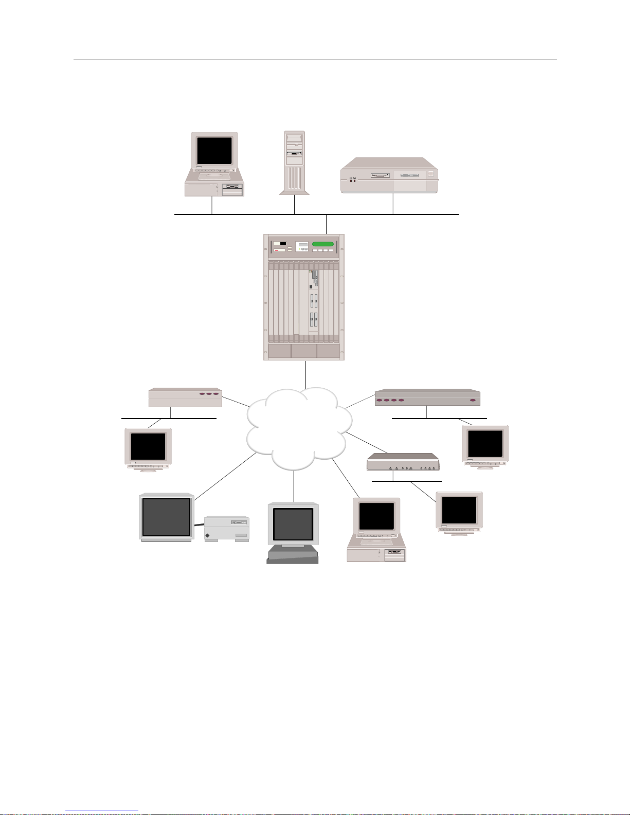
THE SMARTSWITCH REMOTE ACCESS MODULE NETWORK
The SmartS witc h Remote Acces s Modul e can b e used with a mix of br idges, r outers, hos ts, PCs, and
workstation s. These com bina t ions pro vi de inter netwo rk ing cap ab ilitie s that will allo w dev ices to
carry out LAN-to-LAN ap plicat ions such as teleco mmut ing, electron ic mail, mult i-m edia
transmissi on, Imaging, and CAD. Devices “dial up” in to a single system using a multi-line hunt
group to extend the capabilit ies o ffere d by an enter prise LAN .
Page 16
USER’S GUIDE
16 SmartSwitch Remote Access Module
9W006 AND 9W007 FUNCTION ALITY
TELCO INTERFACES
The telco interf aces provide the 9W006 and 9W007 SmartSwitc h Remote Access Modules with an
interface to telephone company-supplied ISDN PRI lines, or with unchannelized or channelized
T1/E1 lines.
Depending on the country where the PRI service is offered, each PRI li ne supports either the 23 or
30 64Kbps B-channels for data, plus on e 64Kbps D-channel for signaling.
INDY
ISDN
Host
File Server
Router
Remote ISDN Bridge
Workstation
Workstation
Silicon Graphics INDY
Sun SPARCstation
PC
(with BRI ISDN TA)
Remote ISDN Bridge
BRI
BRIs or
PRIs
SW 56
Workstation
BRI
BRI
BRI
MMAC-Plus with
SmartSWITCH
Remote Access Module
MMAC PLUS
Cabletron
Systems
Page 17

9W006 and 9W007 17
THE S
MARTSWITCH REMOTE ACCESS MODULE
9W006 and 9W007 Functionality
The 9W006-220 (the 9W006 with two PRI interfaces and two digital modem interfaces) allows
channelize d T1 ser vic e with rob bed -bit si gn ali ng f or use rs wan tin g t o suppor t anal og mod em ca lls
without concurrent ISDN support.
DIGITAL MODEM
The module’s digi tal modem ca pa bilit y allow s analo g mode m s to be intermix e d with ISD N as
required to best fit specific user situations.
Up to sixty 56Kbps digital modem connections are supported. The digital modem is connected
internally to the telco interface (ISDN PRI or channelized T1) eliminating the need for separate
analog telco connections.
When the modules identify that a call is coming from an analog modem, the associated ISDN Bchannel or channelized T1 SD0 data st ream is th en assign ed to one of th e digital mod ems. A ll of the
operati ons of a 56Kbps modem are pe rf ormed just as if the call had gone to an analog modem
through an analog phone line (although at the higher speeds available with digital modem
technology).
Similarly, data coming into the modules (typically from the LAN) is converted to Async-PPP, sent
to the digital modem fo r modulation, and sent ou t the ISDN B-ch annel or T1 DS0 on th e telco line.
The K56flex digital modem protocol provides automatic rate detection/negotiation such that lower
baud rates are fully supported. The digital modem also supports MNP4 and V.42 error control
protocols, and MNP5 and V.42bis data compressi on protocols.
MANAGEMENT
The SmartS witch Remote Access Module inc ludes SFVRA-CFG, a mana ge me nt software with
flexible bandwidth management designed to keep performance up and cost down. Network
manager s can configure a varie ty of par a me ters to control co nn e ctions being established and
terminated including restrictions by packet type, time of day, and maximum calls per day.
The management capabilities included allow great flexibility. Each B channel can be used to
connect to one or mo re si ngle remo te lo cat i ons, or thr oug h inv ers e mu lti pl ex ing h igh er band wid th
can be provided to users in multiples of 64Kbps.
Users ca n als o config u re the module s to se nse data traffic nee ds and au to m a ti cally in itiate or
terminate calls. This provides bandwidth-on-demand resulting in high performance with minimal
associated cost. The management of these calls is extremely important for minimizing ISDN phone
charges.
Remote managem ent capab ilitie s are also suppo rted for centraliz ed adm inis tration of
dece ntralize d n e tw orks incl uding th e us e of sta ndards such as SN MP and Tel n e t.
The 9W006 and 9W007 modules provide numero us network management features . Internally , Call
Detail Recording will log data to a local file. Using Syslog users can capture essential data regarding
remote users connection time. Also supported is Telnet with password, host and terminal server as
well as tftp for the ability to upload and download log files. CDR files provide tracking and
Page 18

USER’S GUIDE
18 SmartSwitch Remote Access Module
troubleshooting capabilities while the system is up and running. The modules also support SNMP
with both MIB II, private extensions, and a container MIB indicating the current configur ation.
ADDITIONAL SOFTWARE
Cabletron also supplies two separate software products that are used in conjunction with the
SmartSwitch Remote Access Modules: SFVRA Config u ration Manager (SFVRA-CFG ) and SFVRA
Connection Manager (SFVRA-CONN).
SFVRA-CFG provides a GUI interface for configuring the SmartSwitch Remote Access Module.
Through the SFVRA-CFG, the netw ork administrator can deploy and maintain an entire
CyberS WI T CH network through a cen tr al l y located devi ce . The net work adm in is trator can
generate each system’s configuration files separately, with the system’s view of the network, then
transfe r th e configuration files elec tronically to the system.
SFVRA-CONN offe rs st at e of th e a rt poli cy-base d ma nagem ent sy st em fo r lar ge ce ntr al si te dial-i n
networks. This sof tware provides a rich set of network config uration, management, and reporting
capabilities. The functionality of SFVRA-CONN software includes policy-based connectivity
management, virtual networking that spans multiple modules (including multiple SmartSwitch
9000 chassis, and even includ ing multi p l e geo graph i c si tes) with audit/account i ng ca pabi lities.
UNIQUE SYSTEM FEATURES
The SmartS witch Remote Access Module co mbines unique fe atures that improve costeffectiveness, reliability, and performance for wide area network connections to remote devices.
These features include:
• Authentication Servers
Provide a central database for networks with more than one SmartSwitch Remote Access
Module. The central database consists of manageable, informational data (referred to as the
Device List or Device Table). This data is accessed and used for authentica tion when a new
connection is estab lished to the system.
• Bandwidth Agility
The system dynamically controls the bandwidth in use between itself and other PPP devices.
This is accomplished by estab lishing a nd dis c onn ecting calls . The num be r of calls is limited
only by the types and number of lines available. The system monitors the connections for
utilization and will add an d remove the connec tions based on use r- configurable throughput
parameters. As network ba ndw id th requirem ent s increa se or decrea se, the system will
automati cally adju st th e nu mber of ne twork con nect ion s. Thus, your n et work costs w il l ref lec t
the actual bandwidth being used.
• Data Compression
Allows the system to negotiate compression algorithms with another device on the network.
After successfully negotiating com p re ssion, data is compressed by the remote device and
transmi tte d to the system. The system deco mp resses the data, processes the information
contained in the user data, and forwards the data as required. The system can receive data
coming over a WAN or a LAN, and compress the data before transmitting it to another device
on the network. The net ef fect is to i ncrease int erconnect bandwidth by decrea sing
transmi ssion time. If negotiati on for compre ssion fails, data is transmitted uncomp ressed.
Page 19

9W006 and 9W007 19
THE S
MARTSWITCH REMOTE ACCESS MODULE
Unique System Features
• Dial Out Capability
The system will dial out to remo te dev ices . Th is featur e allows the sy st em to accep t user data
receiv e d on the Ethernet LA N or I S DN network and initiate a data connectio n to the remote
device specified in the user data. This allows devices on the local LAN to initiate connections
to networks connected to the syste m over the switched digital network . Th e system monitors
the connection for utilization and will rem ove the connection when it becomes idle.
• Digital Modem
The system becomes an analog modem pool through its digital modem option. The system
supports analog modem calls for high density channelized T1 lines using Robbed-Bit
Signaling. It also supports 56Kbps digital modem technology (K56flex) with auto negotiation
to automatically adapt to various modem speeds. The digital modem adapter consists of both
hardware and software ele ments to support up to 48/60 analog and/or digital connections in
each dua l- s lo t mo dule.
• Dynamic Management
Provides a “real- time” manageme nt mechan ism that allows many sys t e m p a rameters to be
changed with out interrupti ng the current execution state of the system software. Th is feature
consists of a series of console comman ds that enable a user to displa y current system
paramet ers , c ha ng e man y par ame ter s d yna mica lly , and wri t e cha ng es t o d isk f il es s o th at the y
remain permanent.
• High Speed Digital Connections
The system supp orts 56Kbps and 64Kbps co nnections to remote locatio ns. These dial- up digital
connections provide re liable high throughpu t connections for efficient data transfer for the
same cost as analog connections. If any r e mote devices conn e cted to the system support multilink PPP, up to 32 parallel connections can be made at either 56Kbps or 64Kbps.
• Hot Swappable Modules
SmartSwitch Remote Access Modules are hot swapp able. SFVRA Co nfiguration Manager
(VRA-CFG) can retai n the confi guration and setup of the module and auto maticall y download
the required information to a replacement module.
• Inverse Multiplexing
The modules provide inv ers e mult iple xin g for bo th ISDN a nd ana lo g mo dem con nect ion s
supporting an aggregated bandwidth in multi pl e s of 56/ 64K bps.
• Layer 3 Switching Support
The SmartS witch Remote Access Modules provide layer 3 switching support for IP, IPX, and
AppleTalk. Also provided is multiprotocol layer 2 switching.
•Packet Capture
In order to monitor incoming LAN data, the SmartSwitch Remote Access Module packet
capture feature will allow you to capture, display, save, and load bridged or routed data
packets.
• Proto col Discrimination
It is possible for multiple types of remote devices to use the same line. The system can
determine the device type and the protocol encapsulation used by remote devices.
Page 20

USER’S GUIDE
20 SmartSwitch Remote Access Module
•Security
Security is a key issue for all central site network mana gers and is a priority with the
SmartSwitch Remote Access Modules. The modules provide high level features that help
prevent unauthorized or i nadvertent ac cess to criti cal data and r esources. The modules suppor t
extensive security levels includ ing:
• PPP PAP and CHAP
• User na me a nd p a ss w or d
• Calling Line ID (CLID)
• Ethernet Address
• User Authentication
• Device Authentication
• SecureFast Virtual Remote Access (SFVRA)
• Simultaneous Connections
The system supp orts simultaneo u s connectio n s to multiple l o ca t i ons. Thes e lo ca tions can
connect by using different channels on the same line, or they can connect on different lines. This
pooling of lines among many poten tial loc ations is more cost effective than alternative pointto-point lines.
INTEROPERABILITY OVERVIEW
“Interoperability” is the ability to operate and exchange information in a heterogeneous network.
The SmartS witch Remote Access Module supp orts interoperability with many diff erent remote
devices over ISDN.
INTEROPERABILITY PROTOCOLS
In ord e r to communicate with various remote devices over ISDN, the SmartSwitch Remote Access
Module mus t id e ntify the device type and th e pr otocol it is using.
The SmartSwitch Remote Acc e ss M odule supports the following l ine p rotocols:
• HDLC Ethernet Frames
• Ordered Protocol for Ethernet Frames
• RFC1294 Based Encapsulation for IP Datagrams
• Point-to-Point Protocol (PPP) Encapsulation for IP Datagrams
The SmartSwitch Remote Acc e ss M odule supports the following P PP protocols:
• Link Control Protocol (LCP)
• Multilink Protocol (MLP)
• Authentication Protocols
Challenge Handshake Authen tication Protocol (CHAP)
Password Authentication Protocol (PAP)
• Netwo rk Control Protocols (NCP)
Interne t P rotocol Control Protocol for TCP/IP (IPCP)
Intern e t work Packet Exchange Co ntrol Protocol for IPX (I PXCP)
Bridge Control Pro toc ol for bridg es (BCP)
• Compression Control Protocol (CCP)
• AppleTalk Control Protocol (ATCP)
The SmartSwitch Remote Acc e ss M odule supports the following Appl e Talk protocols:
• EtherTalk Link Access Protocol (ELAP)
Page 21

9W006 and 9W007 21
THE S
MARTSWITCH REMOTE ACCESS MODULE
Security Overview
• AppleTalk Ad dress Resoluti on Protocol (AARP)
• PPP AppleTalk/AppleTalk Control Protocol (ATCP)
• Datagram Delivery Protocol (DD P)
• Routin g Ta b le Maintenance P rotocol (RTMP)
• AppleTalk Echo Protocol (AEP)
• Name Binding Protoco l (NBP)
• Zone Information Protocol (ZIP)
INTEROPERABILITY DEVICES
Remote devi ces t hat may conne ct to th e SmartS witch Re mote Acce ss Modul e inclu de the fol lowin g:
• MAC Laye r Br idge s
•IP Host Devices
• IP Router Devices
• IPX Routers
• AppleTalk Routers
MAC layer bridge s connec t to the syste m using the HD LC bridge encap sula tion line p rotoc ol .
These devi ces send transpar ently bridged E therne t frames to the sy stem. MAC layer br idges do not
process ne twork layer protocols. The y forward all packets based on source and destinati on MAC
addresses.
IP Host devices are single workstations or PCs that co nne ct to the system at the IP network layer.
These devices use either the RFC1294 based protocol or PPP to communicate with the system.
IP router devices are single devices that represent many ot her IP hosts and ro uters to the syste m.
They must use the CHAP or PAP protocol to identif y themselves to the system. IP routers usually
provide IP network address information at connection time (and use PPP to send user data to the
system).
IPX routers are single devices that perform network layer tasks (addressing, routing, and
switchin g) to move packet s from one location on the network to anot her. IPX ro u te rs use the
Internetwork Packet Exchange (IPX) protocol, typical of the NetWare environment.
AppleTalk routers route AppleTalk datagrams based on address information. They support the
following protocols: RTMP, NBP, and ZIP.
SECURITY OVERVIEW
The system provides se veral options for valid ating remote devices and for managing network
security. The security options available are dependen t on the remote device type, type of access ,
and the level of security required.
Page 22
USER’S GUIDE
22 SmartSwitch Remote Access Module
NETWORK INTERFACE OVERVIEW
The network i nterface is th e p hysical conn e ction of the SmartSwitch Remote Access Module to a
data network . Fo r example , the Ether net res ou rce in th e system provi des a net work inter face to an
Ethernet LAN. The ISDN lines in the syste m provide network interfaces to multi ple remote
networks. Because of their sw itched nature, the IS DN lines provide virtual network interfaces. That
is, the same physical ISDN line can actually connect to different remote networks by dialing a
different phone number.
The SmartSwitch Remote Access Module provides a set of network interfaces that give you a wide
range of flexibility. The network interfaces provided by the system are:
• LAN IP Network Interface
• LAN IPX Network Interface
• WAN IP Network Interface
• WAN RLAN IP Network Interface
• WAN RLAN IPX Network Interface
• WAN (UnNumbered) Network Interface
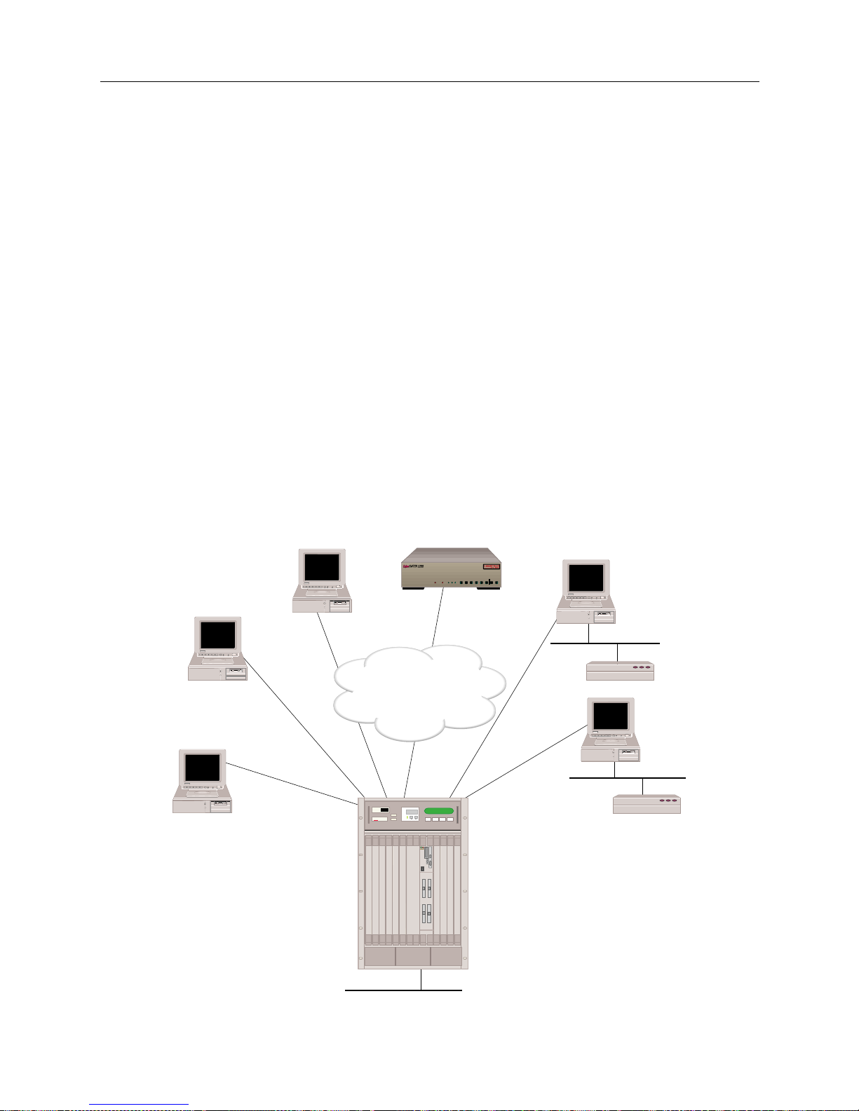
The variety of ne twork interfaces allows the instal lation of a wide range of de vices at remote sites.
As illustrated below, you can simultaneously choose bridges, routers, or host devices based on the
speci f ic re mote si te re qu i r e ments.
ISDN
128.1.1.2
Host
128.1.1.3
Host
192.1.1.2
Host
(or Router)
192.1.1.3
CyberSWITCH
100.1.1.2
Remote
Bridge
Remote
Bridge
100.1.1.3
WAN Direct Host
Interface
RLAN
100.1.1.1
WAN
Interface
192.1.1.1
LAN Interface 128.1.1.1
MMAC-Plus with
SmartSWITCH
Remote Access Module
MMAC PLUS
Cabletron
Systems
B25B27
B26B28
WORKGROUP REMOTE ACCESS SWITCH
B29
E1 ONLYB-CHANNELS
LAN
10BASE-TRXTXSERVICE
B31
B30L1
B21B23
B22B24
B17B19
B18B20
B13B15
B14B16
E1DT1
D
B9B11
B10B12
B5 B7
B6 B8
B1 B3
B2 B4
POWER
Page 23

9W006 and 9W007 23
THE S
MARTSWITCH REMOTE ACCESS MODULE
System Components
In the diagram above, t he LAN Interface 128.1. 1.1 is attach ed to the IP network 128. 1.0.0. The WAN
Direct Host Int erface represent s LAN Interface 128. 1.1.1 and all ows the remote IP h osts to share the
network address space of 128.1.0.0. The WAN Interface 192.1.1.1 is logically attached to the IP
network 192.1.1.0. The RLAN Interface 100.1.1.1 is logically attached to the IP network 100.1.1.0.
SYSTEM COMPONENTS
The major components of th e SmartSwitch Remote Access Module are:
• System h ar dware con sis tin g of a module an d an a dmini st rati on p ort p rovi de d by the p latf orm .
• System software specific to the SmartSwitch Remote Access Modul e , adapter modules, and
administration functions.
• Administration software that provides configuration, diagnostics and maintenance on the
system.
• System files containing configuration and operational information.
• Remote ISDN devices which interoperate with the system an d allow device access to network
resources.
More deta iled desc ripti ons of sy stem so ftware an d hardwar e are included in the nex t two chap ters .
The following section describes remote ISDN devices.
REMOTE ISDN DEVICES
The SmartS witch Remote Access Module provides a centralized concentrator function for remote
ISDN devices. Th e devices can be separated into the following categories:
• remote ISDN bridge devices
• PC based terminal adapters
• ISDN enabled workstations
• other ISDN routers
Typical remote ISDN bridges provide one Ethernet port and one basic rate ISDN port. The basic
rate port is connected to the switched digital network and is used to make connections to the
SmartSwitch Remote Access Module. The Ethernet port is used to connect to a remote LAN. The
remote br idge device sends Ether net frames from devices on the remote LA N over the switched
network.
PC-based terminal adapte rs connect to a remote personal compute r an d us e the switche d d igital
network to con nect to the system. The termi nal adapter sends network protoc ol specific f rames
from the host PC device over the switched network.
Workstat ion-based terminal adapters connect to a workstation and us e the switched digi tal
network to con nect to the system. The termi nal adapter sends network protoc ol specific f rames
from the wor kstation over the switched network .
Page 24

USER’S GUIDE
24 SmartSwitch Remote Access Module
SWITCHES SUPPORTED
The SmartS witch Remote Access Modules support the following ISDN PRI switch types:
• AT&T D efinity
• AT&T 4ESS
• AT&T 5ESS
• DMS250
• DMS100
• SL100
•NET5
•1TR6
•NTT INS
• TSO 14
Page 25

H
ARDWARE OVERVIEW
The SmartS witch Remote Access Modules are versatile wide area networking products design e d
for the SmartSwitch 9000. T hey are installed directly into the SmartSwitch 9000, expanding the
SmartSwitch 9000 architecture to provide ISDN and analog modem access.
This chapter provides a description of the fol lowing:
• module hardware
• SmartSwitch 9000 chassis support for the modules
• System Management Bus (SMB)
For installation instructions, refer to Hardware Installation.
SMARTSWITCH REMOTE ACCESS MODULE HARDWARE
This section provid e s an overview of the module’s hardware by descr ibing the SmartSwitch
Remote Access Module’s:
• availab le h ardware conf iguration s
• hardware charac teristics
•interfaces
•LEDs
• ports and connectors
AVAILABLE HARDWARE CONFIGURATIONS
There are two families of SmartSwitch Remote Access Modules: the 9W006 modules for countries
using T1 lines, and the 9W007 modules for countries using E1 lines. Each module family consists
of three possible configurations for remote access connectivity. We summarize the possible
configurations for each modu le family be low.
The 9W006 module configured for T1 countries and is available in the following configurations:
• 9W006-200
This model provides an interface for two ISDN PRI or T1 lines (either unchannelized or
channelized) supporting up to 46 or 48 connections.
• 9W006-400
This model provides an interface for four ISDN PRI or T1 lines (either unchannelized or
channelized) supporting up to 92 or 96 connections.
• 9W006-220
This model provides an interface for two PRI or T1 lines (channelized), and two digital modems
(24-port) supportin g up to 46 or 48 digit al or analog connections.
The 9W007 module is configured for E1 countries and is available in the following configuratio ns :
• 9W007-200
This model provides an interface for two ISDN PRI or E1 lines (either unchannelized or
channelized) supporting up to 60 connections.
Page 26

USER’S GUIDE
26 SmartSwitch Remote Access Module
• 9W007-400
This model provides an interface for four ISDN PRI or E1 lines (either unchannelized or
channelized) supporting up to 120 connections.
• 9W007-220
This model provides an interface for two PRI or E1 (channelized), and two digital modems (30port) supporting up to 60 digital or analog connections.
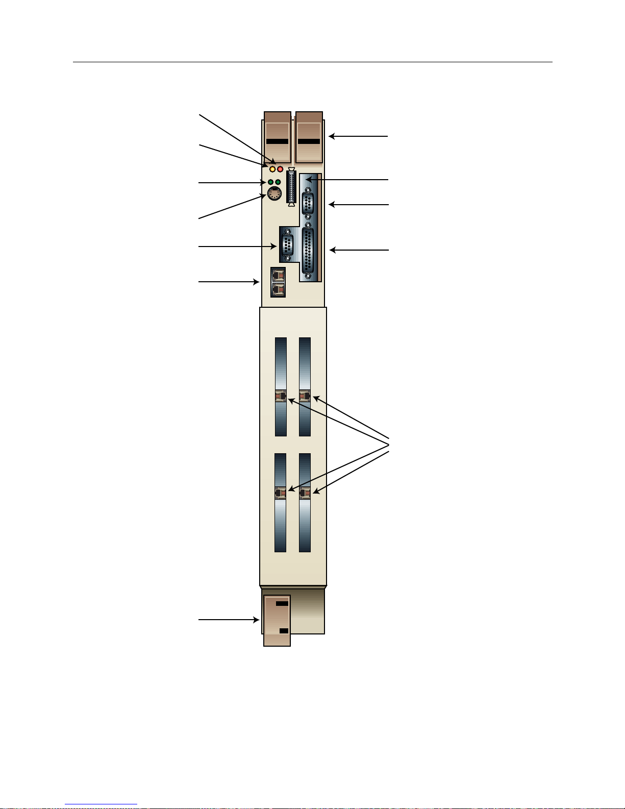
The following graphic illustrates the 9W006-400 module. Note that the 9W007-400 has identical
physical features (connectors, ports, etc.). The remaining modules have the same physical features
with the excepti on o f the configura tion o f the WAN inte rface po rts. The 9 W006- 200 and t he 9W0 07200 have two PRI interfaces, as does the 9W006-220 and 9W007-220 (their modem interfaces ar e
internal).
Page 27
9W006 and 9W007 27
H
ARDWARE OVERVIEW
SmartSwitch Remote Access Module Hardware
MMAC
BUSMMAC
Smart
SWITCH
1
1
2
3
24
9W006-400
WAN
Ejector Tabs
External Floppy
Drive Connector
RS232 Console
Connector
Ethernet Ports
VGA Video Ports
Ethernet 1 & 2
Activity LEDs
Keyboard Connector
SMB LED
Power LED
Parallel Port
PRI/TI
Ejector Tab
The 9W006-400
PRI Ports
Page 28

USER’S GUIDE
28 SmartSwitch Remote Access Module
MODULE SPECIFICATIONS
Physical Char acteristics
Height: 45.72 cm (18 in)
Width: 13.97 cm (5.5 in)
Depth: 44.45 cm (17.5 in)
Weight: 10.35 kg maximum (23 lb.)
Environmenta l Characterist ics
Operating Temp: 5° to 40° C (41° to 104° F)
Operating Humidi ty: 20 to 95% non-condensin g
Regulatory Compliance
Meets or exceeds the following:
Safety: UL 1950, CSA C22.2 No. 950, EN 60950, IEC 950,
and 72/23/EEC
EMI: FCC Part 15, EN 55022, CSA 108.8, EN 50082-1,
VCCI V-3, and 89/336/EEC
MODULE INTERFACES
The SmartSwitch Remote Access Module includes the possibility of four flexible WAN interfaces
providing ISDN, analog modem (via digital modem), and T1/E1 or channelized T1 access. As
described earlier, depending on the model, the module may have one of the following interface
configurations:
•four PRI interfaces
•two PRI interfaces
• two PRI interfaces and two digital modems
PRI interfaces provide the module with an i nterface to telephone c ompany-supplied ISDN Primary
Rate Interface (PRI) lines, or with unchannelized or channelized T1/E1 lines. Each PRI interface
supports up to 23 B channels for data and a 64Kbps si g naling D channel (for countries using T1
lines), or up to 30 B channels for data and a 64 Kbps signaling D channel (for countries using E1
lines). The module uses the B channels for switched connections to carry device data. PRI interfaces
have an external port for connecting to the Telco interface.
Digital modem interfaces allow the SmartSwitc h Remote Access Module to recei ve calls from
asynchronous PPP remote devices connected by modem. Each digital modem interface supports
up to 24 56Kbps modem connections (for countries using T1 lin e s), or up to 30 56Kbps mod e m
connections (for countries using E1 lines). Digital modem interfaces are connected internally to the
PRI interface eliminating the need for separate analog telco connections.
MODULE LEDS
The 9W006 and 9W007 has LEDs for the following functions: SMB, power, and Ethern et activity.
Refer to the illustration of the 9W0006-400 for LED locations. We describe these LEDs in the
following sections.
Page 29
9W006 and 9W007 29
H
ARDWARE OVERVIEW
SmartSwitch Remote Access Module Hardware
SMB LED
The SMB LED is an indicator for th e System Manage me nt Buses (SMB-1). This is a 1Mbps
management bus located within the SmartSwitch 9000. It is utilized by al l diagnostic controllers in
the system. These include connectivity modules, power supply modules, and the environmental
modu le . T he S M B-1 tran sp o r ts inter-c h a s si s i nf ormatio n b e tw e e n system compone nts, such as
power and environmental information, as well as diagnostic messages. Periodic loop-back tests are
performe d by all modules that share this bus (which includes the SmartSwitch Remote Acces s
Modules) to ensure the validity of SMB-1.
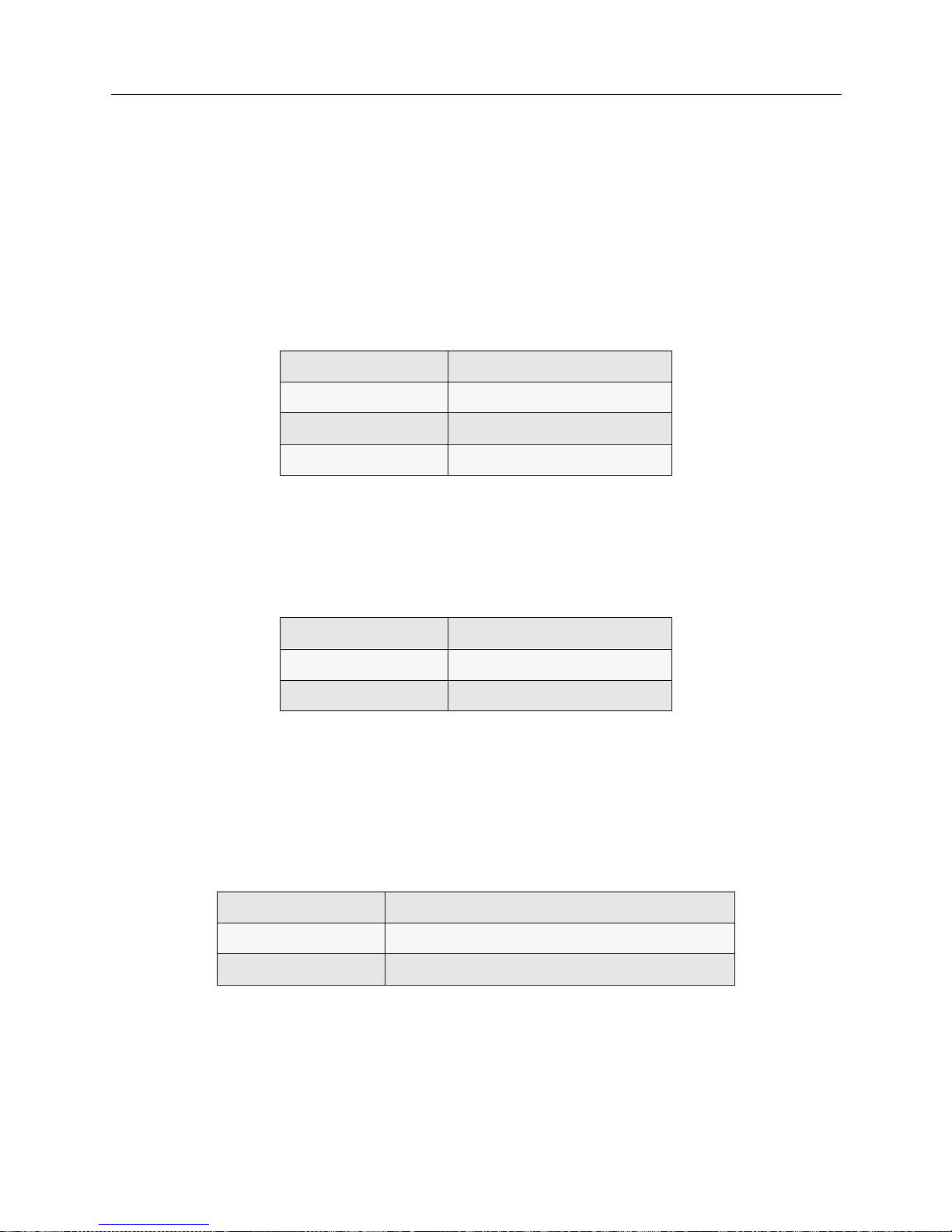
The functi ons of the SMB LED are listed in the following table.
P
OWER LED
The power LED pr ovides information rega rding the module power sta tus. The functions of the
power LED are listed in the following table.
E
THERNET 1 & 2 ACTIVITY LEDS
The Ethernet 1 and 2 LEDs illuminate when the integrated Ethernet controller has activity on either
the transmitting or receiving lines for that channel.
The functions of the Ethernet 1 and 2 LEDs are listed in the fol lowing table.
LED Color Description
green fully operational
red normal power-up reset
off module powere d o ff
LED Color Description
green powered on
off module powere d o ff
LED Color State
green activity on the indicated Ethernet line (1 or 2)
off no activity on the i ndicated Ethernet line (1 or 2)
Page 30

USER’S GUIDE
30 SmartSwitch Remote Access Module
MODULE PORTS AND CONNECTORS
The SmartSwitch Remote Access Module’s front panel h as the following ports and connectors
(refer to the illustration of the 9W0006-400 for locations):
• RS232 console connector
You may use this connector to attach a lap top computer to the module. The lap top can then
provide you with an administration console. The administra tion console is simply a
communication path between you and th e module; you can use this consol e to help you
manage the module. For example, through the console you m ay enter sy stem commands such
as
dr
to display the current report log messages (a valuable diagnostic tool), or
br stats
(or
one of the other statisti cs commands) to display system statistics.
• external floppy dr ive connector
Software upgrades are possible through an external floppy drive connected to the m odule v i a
this connector. The Cabletron external IDE drive (#EAP-EXT3.5-FD) is compatible with this
connector.
• keyboard connector, VGA video port
Using these connectors, you can attach a keyboard and a VGA monitor to provide a local
administration console.
• paral lel port
This port is currently disabled.
• dual ethernet ports
Using these connectors and the provided Ethernet cables, you can connect the module to the
SmartSwitch 9000’ s Ethern et connec tion, giving the mo dule pres ence on the LAN.
•PRI ports
Used for WAN (telco) connection access to support ISDN PRI, T1/E1, and digital modem
service (the digital modem interfaces connect internally to the PRI interfaces; there are no
external ports for the digital modems).
SMARTSWITCH 9000 CHASSIS SUPPOR T
The SmartSwit ch 9000 chas sis p rovid es red und an cy for a high availa bilit y system des ign. Th e
9W006 and 9W007 SmartSwitch Remot e Ac cess Modules are hot swappable. The SFVRA
Configuration Manage r can retain the configu rati on and setup of the module and automa tically
download required information to a replacement module. The module identity "9W000 Remote
Access Module" is conveyed to th e Smar tSwi tch 9000 management module al ong with serial
number, MAC addresses and other identifying information.
The 9W006 and 9W007 modules co nnect to the SmartSwitch 9000 System Management Bus (SMB-
1) and SmartSw itch 9 000 Po wer Bus . They additio nally i nc lude the ir own pro cessor , 32 MB DRAM
memory, and allow local management capability in addition to remote management. Software
upgrades will be supported through a Telnet or remote console connection.
Page 31

9W006 and 9W007 31
H
ARDWARE OVERVIEW
System Management Bus (SMB-1)
SYSTEM MANAGEMENT BUS (SMB-1)
The 9W006 and 9W007 SmartSwitch Remot e Access Modules share infor mati on through the
SmartSwitch 9000 SMB ba ckplane per mittin g con nectiv ity t o the SmartSwit ch 90 00 Envi ronmental
Management Module to control temperature of the board, fans, humidity, and various other
environmental components. The SMB-1 connection also provides visibility in Spectrum for its
Module I.D., 9W000 Remote Access Module, indicating a dual- sl ot module. Modules can be reset
or powered on or of f via Spectr u m allowing maintenance on a selected WAN modul e while the
others in the SmartSwitch 9000 remain operational.
Page 32

S
OFTWARE OVERVIEW
OVERVIEW
The SmartSwitch Remote Acc e ss M odule software p rovides:
• system software for the SmartSwi tch Remote A ccess Module, LA N an d WAN interfaces, and
administration functions
• system files containing configuration and operational information
This chapter provides an overview for each of the above software categories.
SYSTEM SOFTWARE
Included w ith ea ch Smar tSwi tch Rem ote Acc ess Module is a CD cont ain ing upgrad e soft ware and
utility software. (Note that initial system software is factory-installed). The following system
software files are available on the CD:
upgrade.osw
All the system files needed for upgrading the SmartSwitch Remote Access Module are combined
in this file.
defltcfg.osw
All of the system files needed to return your system configuration to the factory default are
combined in this file.
SYSTEM FILES
The system files consist of the required configuration files, as well as the operational files that the
SmartSwitch Remote Access Module mai ntains. All of these fil e s may be accessed by u sing
available administrative commands. (Refer to the System Commands chapter for details.)
Below is a brief description of the configuration and operational f iles .
CONFIGURATION FILES
The configuration files store the configuratio n da ta. These fi les are located in the system’s
\config directory. You can maintain these files by using VRA-CFG, which is delivered with the
system.
The configuration files associated with the system are:
network.nei
This configuration file contains info rma tion about the switched netw ork.
devdb.nei
This file contains the On-node Device Database configuration information about each remote
device.
Page 33

9W006 and 9W007 33
S
OFTWARE OVERVIEW
System Files
node.nei
This configuration file contains node -spec if ic informat ion like resou rce s, lines, SmartSw it ch
Remote Acce ss Module operat in g mode an d secu ri ty op tio ns, al ong wi th th e Thr oug hput Monit or
Configuration inform ati on . If enabled, SN MP configur ation inf orm ation is also in this file.
lan.nei
This file contains configuration information used when the bridge is enabled. This file also contains
information for the Spann ing Tr e e protoco l used for the bridge. Information from this file is
configured and used only when the bridge is enabled.
ip.nei
This file contains configuratio n info rma tion used when th e IP routing is enable d. This file also
contains information regarding network interfaces, RIP, and static routes. Information from this file
is configured and used only when the IP routing is enabled.
ipx.nei
This file contains configuration information used when the IPX routing is enabled. This file also
contains information regarding network interfaces, RIP, and static routes. Information from this file
is configured and used only when the IPX routing is enabled.
filter.nei
This file contains all filter configuration information (bridge, hardware, and IP). This file is new to
Release 7.2 software, but is compatible with previous software versions, which contained filter
information in the lan.nei and/or ip.nei files. With Release 7.2 configuration changes and
configuration file updates, this filter information will be moved to filter.nei.
atalk.nei
This file contains configuration information used when AppleTalk Routing is enabled. This file also
contains information regarding ports and static routes. Information from this file is configured and
used only when the AppleTalk routing is enabled.
sdconf.rec
This is not a system file; it is a configuration file delivered on the ACE Server. However, you may
TFTP th i s file to the sy st e m’s \config directory as an alternate method of providing the system
with ACE Server configurat ion inf ormat ion.
OPERATIONAL FILES
While the SmartSwitch Remote Access Module is running, it collects system statistics and logs
system messages. The system maintains these statistics and messages in two separate memoryresident tables. The ten most recent versions of each table are available on the system disk.
You can re t ri eve and vie w the curren t me m o ry - r e sident tab le s a t an y time by using the fo ll o w i ng
console commands:
dr
This command will display system messages.
ds
This comma nd will display system stat istics.
You can write the tables to disk by using the following commands:
wr
This command will wri te the curren t system mess ages to disk.
ws
This command will wri te the curren t system statistics to disk.
Page 34

USER’S GUIDE
34 SmartSwitch Remote Access Module
Notes: You need an active administra tion session to is su e these commands. Ref e r to Accessing the
SmartSwitch Remote Access Module for instruction s regarding e stablish ing an adminis tration
session.
When the system is shut down, the tables are automatically written to disk.
The system stores the tables in ASCII format files on the System disk. When the system writes
system messages to disk, it store s them in the foll owing locat ion:
Directory: \log
File Name: rprt_log.nn
Where “nn” is an integer that is incr ement ed e ach time a new file is written.
When the system writes system statistics to dis k, it stores t hem in the following location s:
Directory: \log
File Name: stat_log.nn
Where “nn” is an integer that is incr ement ed e ach time a new file is written.
Page 35

C
ONFIGURATION OVERVIEW
OVERVIEW
We provide the following configurati on tools to set up and/or alter your configuration:
• SFVRA Configuration Manager, the graphical interface utility for basic to intermediate
configurations
• CFGEDIT, the configuration utili ty for more comp lex configur ations
• Manage Mode, the dynamic management utility
SFVRA Configuration Manager (SFVRA-CFG) is a fast and easy way to configure basic features for
your syst em. How ever , SFVRA-C FG is N OT dyn amic . T his me ans that a fte r th e con fi gurat ion fil es
are transf err ed, SFVRA -CFG in te rrup ts nor mal sy stem operati on i n or der to impl ement t he f iles. It
is also important to note that downloading these configu ration files does not update the system’s
existing configuration files, it overwrites them.
The follo wing is a list of some of th e major features that cannot be con f igured by SFVRA-CFG:
• AppleTalk Remote LAN port
• Bridge filters
•DHCP
• File attributes configuration
•Frame Relay
• IP filters
• IPX static routes and services
• Off-node authentication databases
• TFTP configuration
•X.25
For a more complex configuration, CFGEDIT is a comprehensive utility you may wish to use to
configure advanced features for your system. CFGEDIT is also NOT dynamic. This means you will
have to interrupt normal system operations in order to update configurat ion files. (You may do so
by either rebooting, or issuing the
restart
command).
WARNING:
If you use CFGEDIT to make configuration change s you will no longer be able to use
SFVRA-CFG.
Manage Mode provides a real-time management mechanism that allows you to change the
config uration , withou t inte rrupti ng the curren t exec ution s tate of the s ystem so ftwa re. Bu t, beca use
it is dynamic, Manage Mode does have its limitations. So, when making configuration changes, you
usually need to use a combination of both Manage Mode and CFGEDIT.
WARNING:
If you use Manage Mode to make configuration changes you will no longer be able to use
SFVRA-CFG.
You may onl y have one CFGED IT or Dyn amic Mana gement sessio n activ e at a ti me per s ystem. F or
example, if a user is making changes directly to the system using Dynamic Management, and then
a second person at a different location using Telnet attempts changes, access will be denied to the
second person. However , if you have an active CFGEDIT or Dynami c Manage m ent session and
Page 36
USER’S GUIDE
36 SmartSwitch Remote Access Module
you use SFVRA-CFG to d ownl oad con fig urati on fil es, th e fi les wi ll be over writ ten and the sy stem
will reboot. The CFGEDIT o r Dynam ic Mana gem ent session will be canceled , and any cha nges ,
unsaved or saved, will be lost.
With two exceptions, it is possible to completely configure your system using CFGEDIT. The
exceptions are:
1. TFTP configuration
2. file attributes configuration
These two elements can only be configured using Manage Mode.
SFVRA CONFIGURATION MAN AGER
The SFVRA Configuration Manager allows a network to be configured and managed centrally. It
is made up of two com p onents: the SFVRA-CF G database ( u sing either MS SQL Server, or MS
Access) and the SFV RA- CF G cli ent ap plica tio n, wh ich is the in terfac e to the data ba se.
The network administrator can generate each sys te m’s configuration files separately, with the
system’s view of the netwo rk, then transfer the confi guration file s e lectronically to the syste m.
SFVRA-CFG provides a mechanism to define a system at a site, based on administrator-defined
templates and standard configu rations. It also al lows the definit ion of major protoco l networks and
their ISD N lines, mapping t hem to specific sites and then to systems at that site. The configuration
files gene rated by SFVRA-CFG for a specifi c sy stem can be transferred to that sy stem using a
proprietary, secur e p rotocol. For more inform ation on SFVRA-CF G, including installation and
configuration instructio ns, refer to S FVRA Configuration Manager User’s Guide.
STARTING THE SFVRA-CFG APPLICATION
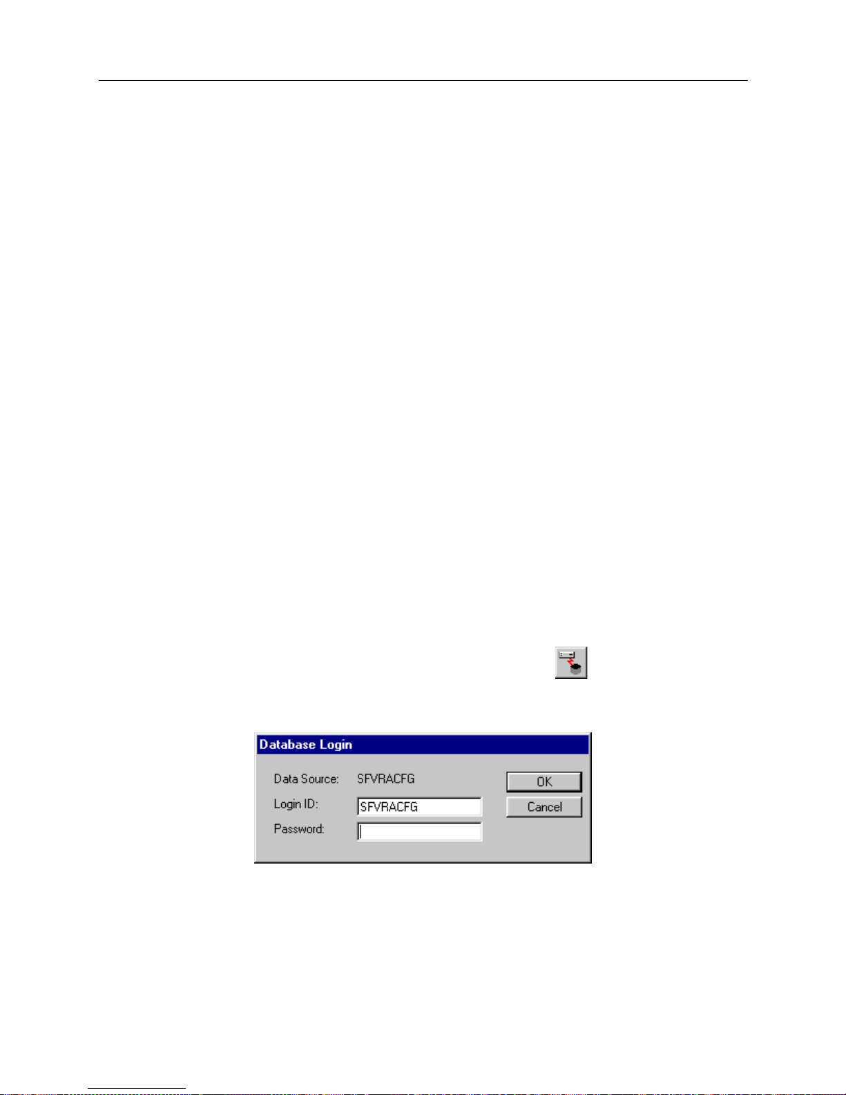
To start the SFVRA - CFG:
1. Open the SFVRA-CFG applicat i on .
3. From the menu bar, clic k on File then click on Connect, or click on the toolbar .
4. A dialog box similar to the following will be displayed:
Note that the first time you use th e SFVRA- CFG appli cati on, the lo gin ID is set to SFVRAC FG.
If desired, you may edit this field t o change the logi n ID.
5. If required, enter your password.
6. Click OK.
Page 37
9W006 and 9W007 37
C
ONFIGURATION OVERVIEW
CFGEDIT
CFGEDIT
CFGEDIT is a menu-driven utility. It consists of multiple, detailed submenus which allow you to
set up or cha n ge co n f ig uration p a ra meters. T o be tter und erstand the st ru cture of CF G ED I T , re f e r
to the CFGEDIT Map in the Appendix of the User ’s Gui de for the Ce nt ra l Si te Cyb erSWITCH .
CFGEDIT allows you to configure your system while the system software is still executing. These
configuration changes are saved in a temporary copy of configuration data. At a convenient time,
you may then reboot the system to make these changes permanent.
Configuration changes made using CFGEDIT are not recognized by SFVRA-CFG. Therefore, once
you use CFGEDIT, you must always use CFGEDIT. This documentation is written under the
assumption that you will use SFVRA-CFG . Howev er, if you plan on using CFGEDIT, refer to the
Central Site documentati on, which is included on the CD-ROM for just such a purpose. In
particular, note that the System Verification and Problem Diagnosis chapters of th e Central Site
CyberSWITCH documentation are written using CFGEDIT techniques. Also, there are three
sections of configuration chapters (Basic, Security, and Advanced Configuration sections) included
in the CyberSWITCH Central Site documentation that are written for the CFGEDIT configuration
utility.
EXECUTING CFGEDIT
After the system software has been loaded, you can start CFGEDIT by entering the following
command at the system prompt as shown below:
[product name]>
cfgedit
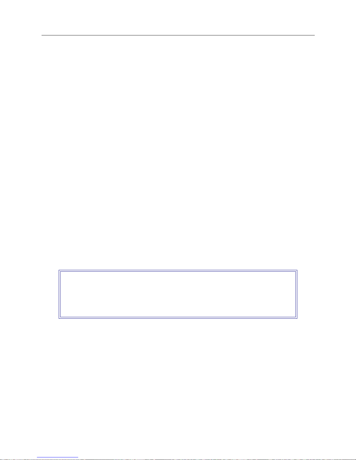
As long as there is no other “change” session active (CFGEDIT or Manage Mode), access is granted,
and the following menu is displayed:
From this screen you will begin the configuration process. Refer to Basic Configurat ion and
succeeding chapters of the User’s Guide for the Central Site CyberSWITCH for details on using this
utility to perform specific configuration tasks.
Remember, changes to CFGEDI T are NOT dynamic. Change s are saved in a temporary copy of
configuration data, and will not affec t the curren t operation of the sy stem in any way.
SAVING CFGEDIT CHANGES
To terminate the session, return to the main CF GED IT menu. If you have made cha nge s, select
option 4 (Save Changes) before exiting. If you attempt to exit without saving, you will be prompted
to do one of the f ollowing:
Main Menu:
1) Physical Resources
2) Options
3) Security
4) Save Changes
Select function from above or <RET> to exit:
Page 38

USER’S GUIDE
38 SmartSwitch Remote Access Module
• save changes (Y) and exit
• do not save changes (N) and exit
• do not save ch anges as yet, but return to the Main Menu for further con figuration <RET>
To save change s a t th is point, an s wer Y for yes:
The save p rocess also includes a ll unsaved Manage Mode change s which were made prior to the
CFGEDIT session, if any.
At your earliest possible convenie nce , restart the Smar tSw itch Remo te Ac cess Module. This will
then activate the new configuration data.
DYNAMIC MANAGE MENT
EXECUTING DYNAMIC MANAGEMENT
The Dynami c Manag emen t fea tur e prov i des a real -t i me man age ment me chan ism; al lo win g yo u to
change th e system’s configuration wi thout interrupti ng the execution of the system software. This
feature c onsi sts of con sole co mman ds that en abl e you to d isp lay cu rren t s ystem par amet e r, ch ange
many para me ters dynam ically, and write changes to disk fil e s so that th e y remain permanent.
However, Manage Mode does have its limitations. Therefore, you will generally need to use both
CFGEDIT and Manage Mode in order to make all appropriate configuration changes.
Configuration changes made using Manage Mode are not recognized by SFVRA-CFG. Therefore,
once you use Manage Mode, you cannot use SFVRA-CFG. This documentation is written under the
assumption that you will use SFVRA-CFG. However, if you plan on using Manage Mode, refer to
the Central Site docum en tatio n, wh ich is includ ed on the CD -RO M for jus t such a pur pose.
Before using Dynamic Management commands, you must first enter the special Manage Mode by
typing the following command at the system prompt:
>manage
Once Manage Mode is entered, the pr ompt changes from [system name]> to [system name]:
MANAGE>. Whil e opera ting i n Manag e Mode, only Dy namic Manageme nt co mmand s are ava ila ble.
All other system commands are ignored until you exit Manage Mode.
The <CTRL><C> key sequence will terminate the current command and return you to the
MANAGE> prompt. This is useful if you are in the process of responding to a series of prompts and
you wish to abort the command without responding to the remaini ng p rompts.
Note: To use a command, you may enter the full command name as it appears in the HELP list,
or you may shorten the command to the point that it can still be distinguished from all
other Dynamic Management commands.
UTILITY DYNAMIC MANAGEMENT COMMANDS
There a re several Manage Mode commands that are used for f unctions other than to configure the
system. They are as follows:
Save changes and exit (Y or N)? or press <RET> for previous menu:
Page 39

9W006 and 9W007 39
C
ONFIGURATION OVERVIEW
Dynamic Management
cls
Clears the display screen. This command is also available as an administrati on command.
help
The Manage Mode help comma nd lists the available Dyna m ic Manage m ent comma nds an d
instructs the user to enter the comman d f ollowed by a question mark to see help information
for that specific comman d.
readme
Displays helpful tips on how to use the Dynamic Management commands.
SAVING DYNAMIC MANAGEMENT CHANGES
The Dynamic Management commands allow s ystem data to be changed in real-time. These
changes take effect immediately upon the execution of the command and remain in effect until the
system is restarted. Once a software restart occurs, the changes are lost because the software reads
its initial system data values from a series of configuration files.
To prevent desired data chan ges from bei ng overwritten by the restart process, the
commit
command should be executed. This command writes the current system data to the appropriate
disk files, thus making all changes pe rmanent, even if the system software is restarted.
The
commit status
command displays the number of dynamic changes that have been made
using ea ch Dynamic Manageme nt command since the last
commit
was performed.
To return to the normal oper ating mode after you have commi tted your changes, issue th e
following command:
MANAGE>
exit
Page 40

S
YSTEM INSTALLATION
We include the followin g chap ter s in this segment of the User’s Guide:
• Ordering ISDN Servi ce
Provides guidelines for ordering ISDN service in the United States.
• Hardware Installation
Step-by-step instructions for installing hardware components.
• Accessing the SmartSw i tch Remote Access Mo d ule
Provides a description of the possible ways to access the SmartSwitch Remote Access Module
(for diagnostic purposes, or for sof tware upgrade).
• Upgrading System Software
A description of the software upgrade process.
Page 41
O
RDERING
PRI ISDN S
ERVICE
(US O
NLY
)
ISDN Primary Rate is a communication s se rvice that allows the system to make up to 23
connections over a sin gle line. It uses a 4-wir e T1 line that carries 24 chann els, each providing 64000
bps bandwidth. The service uses channels 1 to 23 as bearer (B) chan nels to carry connections
between two systems. The 24th channel is used for signaling information (the data link).
You should request the following options for a primary rate line that is connected directly to a
SmartSwitch Remote Access Module:
• B8ZS encoding
• ESF framing
• all channels should be Circuit Switched Data
• Hunt Group (if desired)
• call bandwidth supported (56Kbps, 64Kbps, and/or 384Kbps)
• CLID (calling line Id); usually there is no charge for this
In order to connect to the primary rate line, the customer needs a Channel Service Unit (CSU),
which is integrated in to the SmartSwi tch Remote Acce ss Module . If the line is provided by a LEC
or IXC, the CSU is required by the phone company to protect the phone network from any
problems with customer premise equipment. At the time that the line is ordered, the customer may
be asked for t he F CC reg is tr ation numb er fo r t he Sma rt Switc h Remo te Acc ess Modul e that i s bei ng
used.
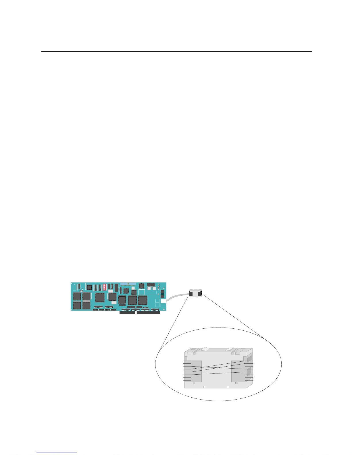
The cabling between the wall jack and the SmartSwitch Remote Access Module is very important,
and is also where most problems occur. The system's PRI RJ-45 ad apter uses the international
standard of pins 3, 4, 5, and 6 for transmit and recei ve. Most T1 lines in the United States and
Europe use the tradition al 1, 2, 4, and 5 pins. We provide an RJ-45 to RJ-45 Mod-Tap adapter that
will convert between the two wiring systems.
RJ-45
Pinout
Adapter
RJ-45
Pinout
Primary Rate Adapter
RJ-45 Jack
1
2
3
4
5
6
7
8
Primary Rate Board
1
2
3
4
5
6
7
8
TX+
RX+
RXTX-
RX+
RX-
TX+
TX-
Page 42
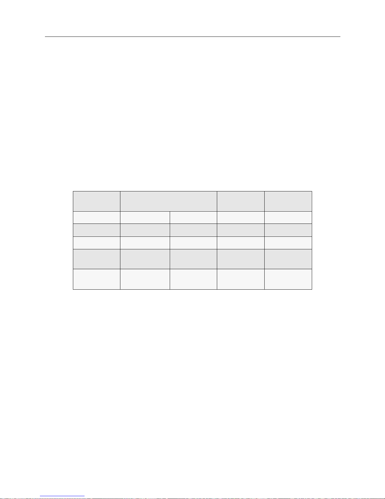
USER’S GUIDE
42 SmartSwitch Remote Access Module
For non-U. S. and European installation s, a standard 4 or 8 wir e cab le with RJ-45 jac k s is sufficien t.
When the line is installed, you must ask the phone company the following questions:
1. What are the phone numbers for the line? (There may be more than one.)
2. Do I need to use any prefix when I dial? (For example, “9” for a Centrex line.)
3. What type of switch is the line connected to?
4. For #4ESS, what relea se of so f t wa re is runnin g on the sw i t ch ?
When the phone company installs the line, they assign it certain characteristics (sometimes called
translations). These are different depending on the type of ISDN switch to which the line is
attached. The customer must know what type of switch is being used.
The following table provides correct settings for important configuration options.
Option Local Bell Operating Company AT&T
Network
U.S. Sprint &
MCI
Type of Switch #5ESS DMS100 #4ESS DMS250
Encoding B8ZS B8ZS B8ZS B8ZS
Framing ESF ESF ESF ESF
Network
Facilities
NA NA SDS or
Call-By-Call
NA
Echo
Cancellation
NA NA NA OFF
(Disabled)
Page 43
H
ARDWARE INSTALLATION
OVERVIEW
This chapte r provides a brief descr iption of the SmartSwitch Remote Access Mod u le hardware
installation process including instructions for:
• installing th e 9W006/9W007 module in to a SmartSwitch 9000
• connecting the module’s cabling
In case you need to restart the module du ring instal lation, instructions are also included for
restarting the module.
INSTALLING THE SMARTSWITCH REMOTE ACCESS MODULE
This section contains instructions for unpacking the SmartSwitch Remote Access Modul e , then
guides you through installing the module into an Smar tSwitch 9000. Instr uctions a re also provided
for res e tting the module.
UNPACKING THE SMARTSWITCH REMOTE ACCESS MODULE
Unpack the SmartSwitch Remote Access Module as follows:
1. Remove the shipping box ma te rial covering the SmartSwitch Remote Ac cess Module.
2. Carefully remove the module from the shipping box. Leave the module in its non-co nductive
bag until you are ready to install.
3. Attach th e di sp osable grounding strap to your wrist and to a proper ground (refer to the
instructions outlined on the groundin g strap package) .
4. After removing the mod ule from its non-conductive bag, visually inspect the device. If you
notice any signs of damage, DO NOT install the module. Contact Cabletron Systems Technical
Support immediately.
Only qualified personnel should install the SmartSwitch
Remote Access Module.
!
CAUTION
The SmartSwitch Remote Access Module and the host
SmartSwitch 9000 are sensitive to static discharges. Use a
grounding strap a nd observe all stat ic precautions dur ing this
procedure. Failure to do so could result in damage to the
SmartSwitch 9000 or the module.
Page 44
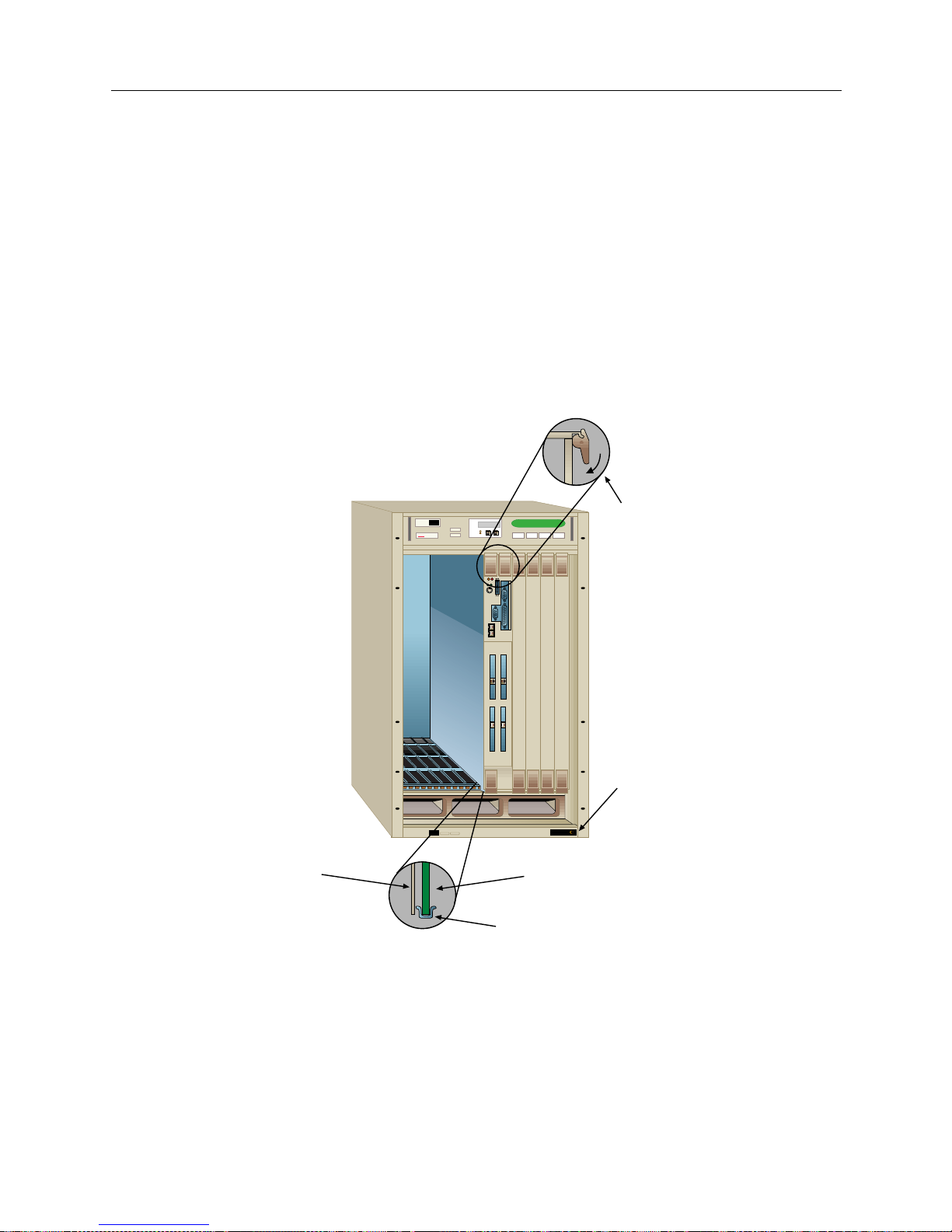
USER’S GUIDE
44 SmartSwitch Remote Access Module
INSTALLATION
1. Note that the module is a double wide module and will fill tw o SmartSwitch 9000 slots.
Remove the Smar tSwitch 9000’s back panels that are covering the two slots into which the
module will be installed. To ens ure pro per ai rflow and co o ling, all other emp ty slots mus t be
covered.
2. Before installing the SmartSwitch Remote Access Module into the chassis, ensure that the
bottom and top plastic tabs are unlocked.
3. Slide the module into the available slots making sure that the module is between the guides as
shown in the following illustration. Check both the upper and lower tracks. Take care that the
module slides in straight and engages the backplane connectors properly.
4. Lock down the top a nd bottom plastic tabs at the same time, applying even pressure .
CONNECTING THE MODULE’S CABLING
Installing the module into the SmartSwitch 9000 automatically completes its power supply and
SMB connections. As you slide the module into place, the module’s power supply and SMB
connectors sl ide into the SmartSwi tch 9000’s power supply an d its SMB-1 BUS. What you will need
MMAC PLUS
MMAC PLUS
Cabletron
Systems
1
1
2
2
34
Ejector Tabs
Jack for ESD
Wrist Strap
Circuit Card
Card Guides
Metal Back Panel
Page 45
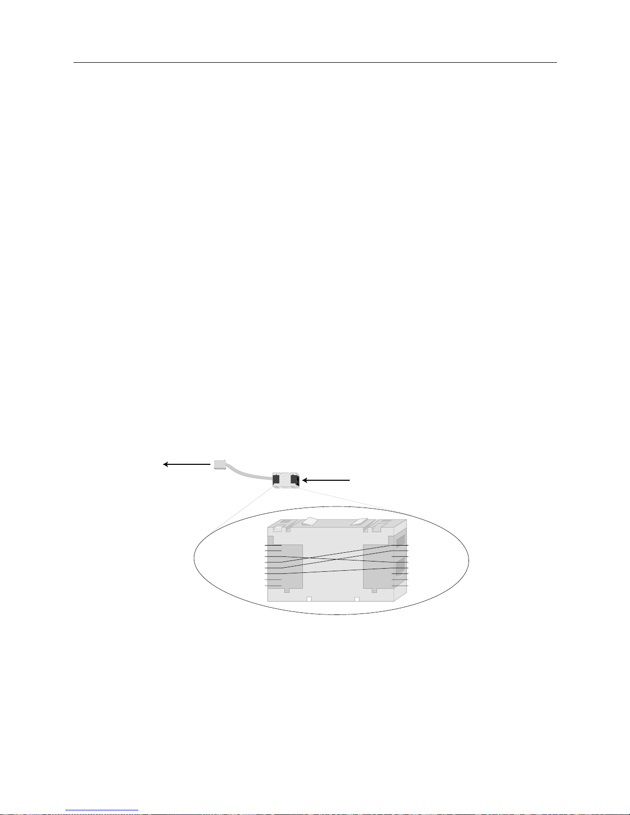
9W006 and 9W007 45
H
ARDWARE INSTALLATION
Connecting the Module’s Cabling
to complete, though, is the Etherne t and PRI cabling. In addition, U.S. and Euro pean installations
need a Mod-Tap adapter for each PRI port. Instructions for each are included below.
MODULE TO SMARTSWITCH 9000 ETHERNET CABLING
We supply two Ethernet cables with the module. Yo u will use thes e cables to connect the module’s
Ethernet inter f a c e (s) to the Sma rtSwitch 9000’s Ethernet conne ction, pr ov i ding the module with
LAN connectivity. To complete the Ethernet cabling:
1. Refer to the illustration of the 9W0006-400 for the Ethernet ports’ locations.
2. Insert the RJ-45 adapter at one end of the provided Ethernet cable into the module’s Ethernet
port 1.
3. Insert the RJ -45 adapter at the other end of the Ethernet cable int o one of the SmartSwitch 9000’s
Ethernet ports.
4. Repeat steps 2 and 3 for Ethernet port 2 if you will be using a second Ethernet connection.
MOD-TAP ADAPTER
The cabling between the wall jack and the module is very important, and is also where most
problems occur. The system's PRI RJ-45 adapter uses the international standard of pins 3, 4, 5, and
6 for transmit and receive. Most T1 lin es in the Un i ted States and E urope use the traditional 1, 2, 4,
and 5 pins. We provide an RJ-45 to RJ-45 Mod-Tap adapter that will convert between the two
wiring systems.
For non-U.S. and Europea n installa tions, stand ar d cablin g is sufficien t (refer to follow ing section).
MODULE TO PRI SERVICE CABLING
The PRI cabling is not included with your module. You will need to determine the length of cable
you need for your connection. The PRI cabling is the same type as the Ethernet cabling: straightthrough twisted-pair cable with RJ-45 adapters at each end. To complete the PRI cabling:
RJ-45
Pinout
Adapter
RJ-45
Pinout
1
2
3
4
5
6
7
8
inserts into
PRI port
1
2
3
4
5
6
7
8
TX+
RX+
RXTX-
RX+
RX-
TX+
TX-
Mod-Tap
Adapter
insert one end of PRI cable here,
other end into PRI service drop
Page 46
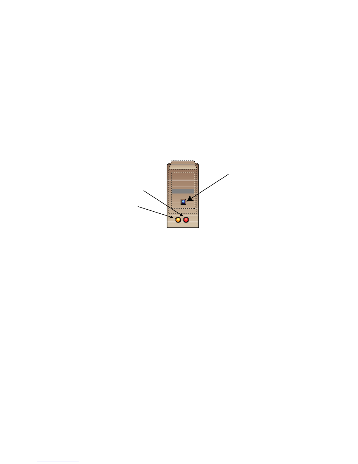
USER’S GUIDE
46 SmartSwitch Remote Access Module
1. Refer to the illustration of the 9W0006-400 for the PRI ports’ locations.
2. Insert the RJ-45 adapter at one end of the PRI cable into either the Mod-Tap adapter (U.S. and
Europe) or di rectly into the module’s PRI port 1 (for all other inst allation s).
3. Insert the RJ -45 adapter at the other end of the PRI cable into your PRI se rvice drop.
4. Repeat steps 2 and 3 for PRI ports 2, 3, and 4 if applicable.
RESTARTING THE SMARTSWITCH REMOTE ACCESS MODULE
The reset sw itch is a rece ssed swi tch locate d on the fr ont panel, under the top -lef t plastic ejector ta b
as illustrated below.
The res et switch se rves two fun c tions:
1. Pre s s i ng th e re s e t sw i t ch twice w it h i n th r e e se co n ds cause s th e pr ocessor to r e se t .
2. Pressing and holding the switch on for three or more consecutive seconds causes the module
to shutdown. Pressing and holding the switch again for three seconds restarts the module.
SNMP managemen t may be used to disable this swi tch to enhan ce module security.
9W006-400
WAN
Reset Switch
SMB LED
Power LED
Page 47

A
CCESSING THE SMARTSWITCH REMOTE ACCESS
M
ODULE
OVERVIEW
This chapter provides instructions for:
• accessing a SmartSwitch Remote Access Module f or the first time
• remote ly accessin g the SmartSwitch Remote Acce ss Module after the first time
Refer to the modul e illustration in Hardware Overview to help you locate the ports described in the
following sections.
ACCESSING A NEW MODULE
The two methods of accessing a new module are:
• access through a PC using a terminal application
• access by Telneting to the module usin g the initial default IP addres s
Once you have u se d one of the tw o me thods to acces s to the module, you should:
• establish an administration sessi on with the module
• assign the module’ s new IP addr ess
• access the module’s re lease note s
For more detailed instructions, refer to the sections below.
INITIAL ASSESS USING A PC AND A TERMINAL APPLICATION
Connect one end of the supplied null mode m cable to th e RS232 console port on the module, and
the other end of the cable to the communication port on the PC. On the PC you must then execute
a communication package to emulate a terminal (VT100).
Use the following default values for your communication package:
Baud rate 9600
Parity None
Data b its 8
Stop bits 1
Duplex Full
After you have connection to the module, you will be ready to establish an ad minis tr ation ses sion.
INITIAL ACCESS USING TELNET
You can use a remote device to the Telnet into modul e using the module’s ini tial d efault I P address
(192.186.254.254). The remote device can be a device with Telnet client software, such as a PC or a
UNIX workstation, or it can be a second module or a Cabletron CyberSWITCH. Note that the
modules and CyberSWITCH systems have built-in Telnet client software.
Page 48

USER’S GUIDE
48 SmartSwitch Remote Access Module
If a SmartSwitch Remote Access Module or second module is acting as the Telnet client, simply
enter the following console command to Telnet into the module:
telnet <
192.186.254.254>
Refer to the System Commands chapter for a complete listing of available Telnet comma nds.
If a remote device other than a Cab letron product is acting as the Tel net client , u se the device’s
Telnet applicat ion to connec t to the initial de fau lt IP address (192.1 86. 254. 254).
After you make a Telnet connection, you will be ready to establish an administration session (refer
to the following section for instructions).
For more information on Telnet, refer to the Remote Management chapter.
ESTABLISHING AN ADMINISTRATION SESSION
Once you have connected to the module using either a terminal application or Telnet, you will be
prompted for a login id. Enter:
admi n
You will then be prompted to enter a password. All preinstalled systems are preconfigured with
the same password. This is the password that is used the first time a login occurs. Being sure to
enter all lowercase letter s as shown b elo w:
admin
You will now see the system prompt. We recommend that you select a new password. To do this,
enter th e following command at the sy stem prompt:
pswd
Follow th e onsc re en inst ruc tion s to ch ange the pa sswor d. N ote t hat t he passw ord mus t be a 3 to 16
nonblank character string, and that it is uppercase and lowerca se sensiti ve.
Next, fol low the instr uctions below to assign the module’s n e w IP address.
ASSIGNING THE MODULE’S IP ADDRESS
To assign the module’s new IP address enter the following command at the system prompt:
ipconfig
As prompted, enter:
• the syste m’s IP address
• the required subnet mask
• for the sy stem’s default route, enter the IP address of the syste m’s defaul t gateway ( e nter 0 if
there is no default route)
Follow the instructions to restart the module so that the configuration changes will take effect.
Once you have assigned the module’s IP address, you will Telnet into the module when you need
access for functions su ch as system mainte nance, diagn osis and veri ficatio n procedures , or entering
console commands.
Page 49

9W006 and 9W007 49
A
CCESSING THE SMARTSWITCH REMOTE ACCESS MODULE
Remote Access using Telnet
ACCESSING THE RELEASE NOTES
The Rele ase Not es provide release highlights and important information related to this release that
should be reviewed before you begin the system’s configuration.
The release notes are in a file called REL_NOTE.TXT. To display the release notes on the system,
enter th e following command at the sy stem prompt:
[system name]> LIST REL_ NOTE.TXT
REMOTE ACCESS USING TELNET
You will use Telnet to remotely access the module for routine system management once initial
installation and configuration has been performed. The same instructions given in Initial Access
Using Telnet can be followed here with one exception, instead of Telneting into the module’s initial
default IP address, you will Telne t to the new IP address you have configur e d for the module.
You will ne ed to est ablish an administ rati on sessi on so that you can issu e consol e comma nds. Once
connected, you will be prompted for a login id. Enter:
admin
You will then be prompted to enter your password. If you have not yet changed the default
passwo rd, enter:
admin
If you have already configured a new password, enter the new password instea d.
Page 50

U
PGRADING SYSTEM SOFTWARE
OVERVIEW
The SmartSwi tch Remote Access Modu le CD contai ns the module ’s upgrad e software . To upgrad e
the module’s software, you will use a device with a CD-ROM drive to Telnet into the module, then
TFTP the new software files to the module.
This chapter describes how to upgrade SmartSwitch Remote Access Module system software.
Instructions are included for the following software upgrade steps:
• settin g up Telnet access
• TFTPing system software upgrade
• accessing Release Notes
TELNET CONNECTION
Through a remote device, you can access the SmartSwitch Remote Access Module using Telnet. To
do this, the device must have Telnet client software. You will Telnet to the module’s IP address.
Note the initial IP address for a new module is 192.186.254.254, but you should have configured a
new IP address for the module dur ing the initial acces s.
Note: Do NOT place mor e than one SmartSwi tch Remote Acce ss Module o n a LAN with the
default IP address. If more th an one module h as the same IP addres s, unpredi ctable res ults
will occur.
After you make a Telnet connection, enter your login id and password. Then you will be presented
with a system prompt and you can enter commands at that time.
UPGRADING SOFTWARE
Perform t he steps below to upgrade the module’s system software:
1. Insert the 9W006/9W007 Remote Acce ss M odule CD-ROM into the PC.
2. Using the PC, Telnet to the module.
3. Once you have an administration session (you have logged in to th e module) enter the special
Manage Mode by typing the following command at the system prompt:
>manage
Note: Once Manage Mode is entered, the prompt changes from [system name]> to
[system name]:MANAGE>.
Page 51

9W006 and 9W007 51
U
PGRADING SYSTEM SOFTWARE
Accessing the Release Notes
4. Change the TFTP configuratio n by typing
tftp change
. The following messages will be
displayed:
Current TFTP Configuration:
The TFTP Feature is enabled.
The TFTP Client is enabled.
The TFTP Server is disabled.
You will be prompted to change the status for each configuration element. Enable the TFTP
Server and assign file access rights to Admin.
5. Use a TFTP client appli cation to PUT the UPGRADE.OSW file from the 9W006/9W007 Remote
Access Mod u le CD-ROM to th e \SYSTEM directory on the mo du le that you want to upgrade .
6. Return to the Telnet consol e and issue the
exit
Manage Mode command.
Note: You will receive a warning that the current configuration data has not been
permanently stored in the configuration files. Do NOT save the TFTP configuratio n
changes.
7. Issue the
restart
console command to complete the Upgrade process.
ACCESSING THE RELEASE NOTES
The Rele ase Not es provide release highlights and important information related to this release that
should be re viewed before you begin the system’s installation an d configuration.
The Release Notes locat e d on the system’s FLASH file system in a fil e called REL_NOTE.TXT. To
display the release notes on the system, enter the following console command at the system
prompt:
[system name]> LIST REL_ NOTE.TXT
Page 52

T
ROUBLESHOOTING
We inc l u de th e f ollowin g ch a p te rs in the Tro ubl eshoot ing se gment of th e User’s Guid e:
• System Verification
After you r SmartSwitch Remote Access Mod u le has been configured, and before proceeding
with normal system operati ons, you may want to verify that the system is functional. System
Verificat ion p rovides instruc tions for verif ying th e syst em hardwar e and syste m confi gurati on.
• Problem Diagnosis
When used in conjunction with System Verification , this material helps diag no se p roblems
encount e red in the verification process.
•System Messages
Provides a l isting of al l system messages, their meanin gs, and when appli cable, poss ible actions
you should take.
• Trace Messages
For certain features you may turn a trace option on, allowing you to tr ack system messages
particu lar to that f e ature. Information is included d e scribing how to turn t he trace options on.
We also list possi ble resu lti ng tr ace m essage s an d thei r mean ings . T he tra ce opt ion is avai labl e
for the following features: call trace and PPP packets.
Page 53

S
YSTEM VERIFICATION
OVERVIEW
After you r SmartSwitch Remote Access Module has been con f igured, and before proceeding with
normal system operation, i t is necessar y to verify that the system is functional. This chap te r
provides instructions for verifying the system hardware and system configurati on.
You only need to perform the verification procedures for the opt ions that apply to your
configuration. For example, if your configuration does not use SNMP, skip the SNMP verification
section.
To perform the verification procedures, WAN lines must be available and ready to use. LAN
attachment componen ts must also be avai lable and ready to use.
During som e of th e pro ced ures , we a sk yo u to en ter an admin ist ra ti on cons ol e com mand. To ent er
these command s, you must ha v e an a ctive adm i ni s tr a ti o n se s s i on . I f yo u nee d instruc tions for
startin g an administration session, refer to Accessing the SmartSwitch Remote Access Module.
Note: At least one remo te devi ce is requir ed to procee d with many of th e verific atio n procedure s.
VERIFYING HARDWARE RESO URC ES AR E OPERATIONAL
To verif y the op e ration of the WAN and LAN hardware resources:
1. At the system prompt, enter the
dr
command to display current system messages. Determine
if the WAN adapter resource is operational by v iewing the syst e m messages. At th e
administration console type:
dr
<return>
2. For each WAN adapter installed, look for these WAN adapter initialization messages among
the system messages:
Bootstrap loaded on WAN card in slot <slot #>, waiting for response
Bootstrap came alive on WAN card in slot <slot #>
Downloading WAN card in slot <slot #> with operational software
Waiting for WAN card in slot <slot #> to complete initialization
WAN card in slot <slot #> signals it is operational
Note: Other me ssa ges ma y al so be dis pla yed w ith the W AN adap ter i ni tial izat ion mes sages.
If you see these WAN adapter initializa ti on mes sages, then the WAN adapter in the indicated
slot is operational.
If these WAN adapter initializati on messages are NOT disp layed for each of your WAN
adapters, refer to WAN Adapter in the Probl em Diagnosis chapter.
Note: A Robbed Bit Signaling line will display a "Layer 1 up" message, but since an RBS
resource d oe s not have an ISDN layer two, a "Data li nk u p " me ssage will not be
displayed.
Page 54

USER’S GUIDE
54 SmartSwitch Remote Access Module
3. Determine if the LAN adapt er resource is operational by view ing the system messages. At the
administration console type:
dr
<return>
The
dr
command displ ays the current sy stem messages. Look for these LAN adapter
initialization messages among the system messages:
LAN Adapter Reset
LAN Adapter ROM version #.#.#
Note: Other me ssages may also be displayed with the LAN adapter initialization me ssages.
If these LAN adapter initialization messages are NOT displayed, refer to LAN Adapter in the
Problem Diagnosis chapter.
4. If you have enabled bridging, look for these LAN adapter initialization messages among the
system messages:
LAN Port <port #> is now in the LISTENING state
LAN Port <port #> is now in the LEARNING state
LAN Port <port #> is now in the FORWARDING state
5. If you have enabled IP routing, look for this LAN adapter initialization message among the
system messages:
[IP] IP router is initialized successfully
Note: Other messages may also be d isplayed with the LAN adapter initialization messages.
If these LAN adapter initialization messages are displayed, then the LAN adapter is operational.
Proceed to th e next section.
If these LAN adapter initialization messages are NOT displayed, refer to LAN Adapter in the
Problem Diagnosis chapter.
VERIFYING WAN LINES ARE AVAILABLE FOR USE
To verify the availability of WAN lines, the WAN resource must already be operational. Also, the
WAN lines must alread y be confi gur ed and co nnec ted to th e Smar tSwit ch Remot e Acc ess Module .
To verify the availabilit y of WAN lines:
1. Determine if WAN lines are operational by viewing the system messages. At the
administration console type:
dr
<return>
The
dr
command displays the curre nt system messages.
2. For eac h primary ra te l ine conf igur ed and att ached to the Sma rtSwitc h Remote Access M odule,
the following line initialization message should be displayed among the system messages:
Data Link up: <slot #> <port #> <ces>
Page 55

9W006 and 9W007 55
S
YSTEM VERIFICATION
Verifying LAN Connection is Operational
Depending on the resource switch type, the system will delay up to 2 minutes before
attempting to bring up the data links.
Note: Other messages may also be displayed with the line initialization messages.
If this message is displayed for each configured line, then the WAN lines are available for use.
If the line initialization message for a configured line is NOT displayed, refer to WAN Line
Availability in the Probl em Diagno si s chapter.
VERIFYING LAN CONNECTION IS OPERATIONAL
To verif y the op e ration of the LAN connection, the Ethern e t LAN adapter re source must already
be operational.
To verif y the op e ration of the LAN connection:
1. Connect th e SmartSwitch Remote Acces s Module to the SmartSwit ch 9000’s properly
terminated Ether net LA N conne c tion.
2. Transmit a test packet onto the Ethernet LAN. At the administration console type:
lan test
<return>
This command will display a message similar to the following:
LAN port 1 Transmit was successful
If the system displays this message, then the test p a cket was trans mitted correctly.
If this mes sage IS NOT di splay ed , then the LA N connec ti on fai le d. Ref er to LAN Attachment in
the Problem Diagnosis chapt er.
VERIFYING BRIDGE IS INITIALIZED
To verify that bridging has initia lize d prop erly :
1. Determine if the bridge is in the forwarding state by viewing the system messages. At the
administration console type:
dr
<return>
2. The
dr
command disp lays the current system messages. L ook for the following LAN adapter
messages amon g the system message s:
LAN Port <port #> is now in the LISTENING state
LAN Port <port #> is now in the LEARNING state
LAN Port <port #> is now in the FORWARDING state
Note: Other messag e s may also be displaye d with these LAN messages.
If you see these bridge initialization messages, then bridging is operational. If these bridge
initialization messages are NOT displayed, refer to Bridge Init ialization in the Problem Diagnosis
chapter.
Page 56

USER’S GUIDE
56 SmartSwitch Remote Access Module
VERIFYING IP ROUTER IS INITIALIZED
To verify that IP routing has initialized properly:
1. View the syst e m messages. At the administration console type:
dr
<return>
2. Look for the following IP message among the system messages:
[IP] IP router is initialized successfully
3. For each IP interface that has been configured, the following interface initialization message
should be disp layed among the system messages.
[IP] Network initialized successfully on ddd.ddd.ddd.ddd
Note: Other messag e s may also be displaye d with the IP rout e r initialization messages.
If you see these IP router initialization messages, then the IP router is operational. If these IP
router initialization messages are NOT displayed, refer to IP Routi ng Initializ ation in the Problem
Diagnosis chapter.
VERIFYING A DEDICATED CONNECTION
To verif y a ded icated connection to the SmartSwitc h Remote Access Module, the WAN lin e s that
are connected to the system must be available for use, and the routing option must be properly
initialized.
To verif y that you have a ded icated connection:
1. View the syst e m messages by entering the followi ng console command:
dr
<return>
2. Look for the following system message among the displayed mess ages:
Layer 1 sync not seen - Slot=<slot #> Port=<port #> Ces=<communication
endpoint suffix>
If the above message appears, a physical problem has been detected on the indicated line.
Check for a proper connection to the Smar tSwitch Remot e Access Module and to the NT1 or
CIU. If the NT1 or CIU appears to be functioning properly, call your carrier service and report
the problem.
If the above message does not appear in the displayed messages, pr oceed to the next step.
3. Look for the following system message among the displayed mess ages:
Dedicated connection to device <device name> up: Slot=<slot#>,
Port=<port #>
If the abov e me ssage is displayed, the dedicated connection is fun ctioning .
If the following message appears, the dedicated connection is not functioning.
Dedicated connection down: Slot=<slot#>, Port=<port #>
Page 57

9W006 and 9W007 57
S
YSTEM VERIFICATION
Verifying Remote Device Connectivity
Refer t o R emote Device Connectivity in the Pro ble m Di agno si s chapter. Because all remote devices
that use dedicated connections are PPP devices, follow the described set-up procedure, then
skip to the step specific for PPP devices.
VERIFYING REMOTE DEVICE CONNECTIVITY
To verif y r e mote device connectivity to the Smar tSwitch Remote Access Module, the WAN lines
that are co nnected to the sy stem m ust be avai lable fo r use, an d the bri dging a nd/or rou ting opt ions
must be properly initialized. The remote devices must be operational and available to initiate ISDN
WAN co nnections.
The method of connection i nitiatio n is dependent upon the remote device type. Refer to the remote
device document ati on to det erm ine how to initiate an ISDN W AN conne ctio n.
To verify remote device connectivity:
1. In a controlled manner, initiate an ISDN connection from each remote device.
2. When each remote device connects to the system, it will appear as either a “REMOTE site” or
as the configured Device Name (if security is enabled) on the Monitor Connections screen. To
display t he Monitor Connections screen, enter the following console command :
mc
<return>
Note: The terminal type must be the same for Telnet and the terminal emulation. Use the
term set
administration console command to set the terminal type.
If each remot e devi ce is ab le t o c onnec t to t he Smar tS witc h Remot e Acc ess M odul e, t he n WAN
connectivity is successful.
If a remote device is NOT able to connect to the system, then refer to Remote Device Connectivity
in the Problem Diagnosis chapter.
VERIFYING IP ROUTING OVER INTERFACES
The following sections provide a method of verifying that IP routing is operational over the
available interfaces .
VERIFYING IP ROUTING OVER A LAN INTERFACE
To verif y that IP routing is operati ng properly ov e r the LAN connection, an IP host must be
connected to the loca l LAN port on the SmartSwitch Remot e Access Module . Th e host must be
properly configured and operational on the IP network to which it is connected.
Below is an example of a configuration used to verify IP ro utin g ove r a LAN connection. It uses IP
addresses specific to the example. Substitute the IP addresses of your network when you perform
the IP ro u ti n g ve rif ication st e p s .
Page 58
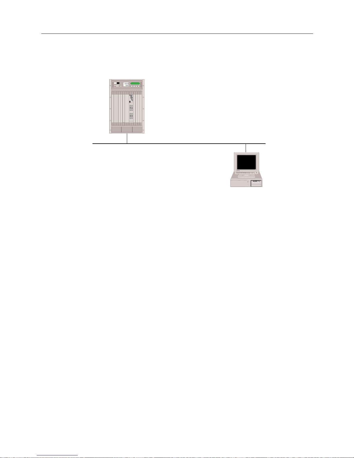
USER’S GUIDE
58 SmartSwitch Remote Access Module
To verif y IP Routin g ov e r a LA N co n nection:
1. Determi ne if the SmartSwitch Remote Access Module can access the l ocal IP host. On the
administration console type:
ip ping 100.0.0.2
<return>
Issuing this command will result in a response similar to the following:
100.000.000.002 is alive
If the system displays this message, then IP routing over that LAN port is operational. Repeat
this step for each LAN port on your Ethernet resource.
If this message IS NOT displayed, then IP routing over the LAN connection is not operational.
Refer to IP Routing Over the LAN Connection in the Problem Diag nosis chapter.
2. Once IP routing is operational on each LAN port on your Ethernet resource, then IP r outing
over the LAN Connection is operational.
VERIFYING IP ROUTING OVER A WAN INTERFACE
To verify that IP routing is properly operational over a WAN interface, a remote IP Host must be
operational and available to initiate connections. Also, a local IP host must be connected to the local
LAN port of the SmartSwitch Remote Access M odule.
Below is an example of a configuration used to verify IP routing over a WAN interface. It uses IP
addresses specific to the example. Substitute the IP addresses of your network when you perform
the verification steps. It also uses the “ping” command. The “ping” command sends a packet to a
specifi e d host, wa its for a response , and reports success or f a ilure. Subs titute the equivalent
command on your IP host.
Host A
100.0.0.1
100.0.0.0
100.0.0.2
MMAC PLUS
Cabletron
Systems
MMAC-Plus with
SmartSWITCH
Remote Access Module
Page 59
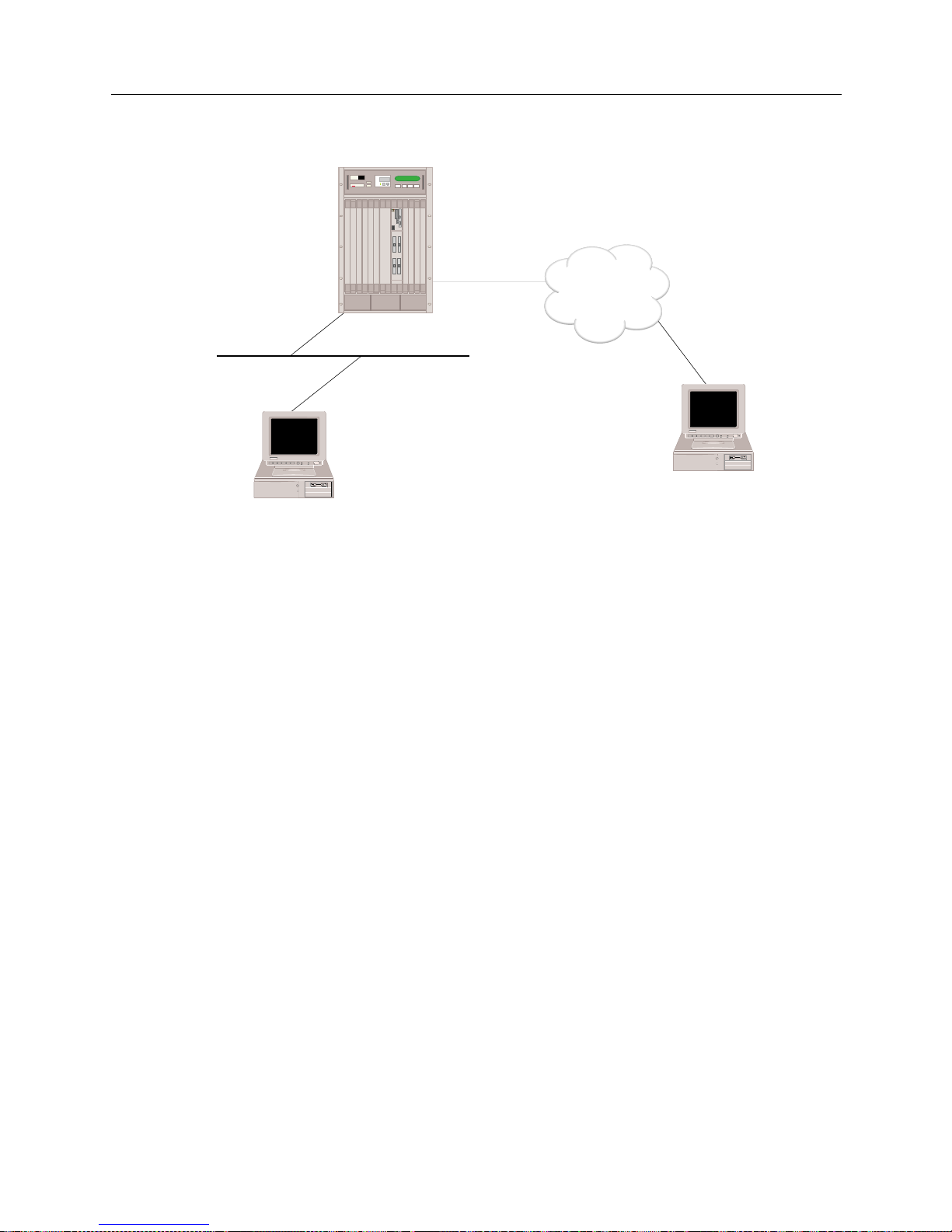
9W006 and 9W007 59
S
YSTEM VERIFICATION
Verifying IP Routing Over Interfaces
The steps to verify the operation of IP routing over a WAN interface are:
1. Determin e if a r emot e I P host c an ac cess the WA N inter fac e of th e Smart Swi tch Remo te Acces s
Module ove r the WAN connec tion. On the remote IP host, type:
ping 192.100.1.1
<return>
If the remote IP host successfully pings to the SmartSwitch Remote Access Module, then
contin u e wi t h the next ste p .
If the remote IP host CANNOT ping to the system, refer to IP Routing Over a WAN Interface
Connection in the Problem Diagnosis chapter.
2. Determine if a r e mote IP host can access the LAN interface of the SmartSwitch Remote Acces s
Module ove r the WAN connec tion. On the remote IP host type:
ping 100.0.0.1
<return>
If the remote IP host successfully pings to the SmartSwitch Remote Access Module, then
contin u e wi t h the next ste p .
If the rem ote IP host CANNOT ping to the Smart S witch Remote Access Module, refer to IP
Routing Over a WAN Interface Connection in the Problem Dia gnosis chapter.
3. Determi ne if a remote IP host can acces s the local IP host through the system over the WAN
connection. On the remote IP host type:
ping 100.0.0.2
<return>
If the rem ote IP host successfully pings to the local IP host, then I P r outing over WAN type
interface is operational. Repeat the above steps for each WAN type interface through which
you wish to get access.
192.100.1.1
100.0.0.1
100.0.0.0
Host A
100.0.0.2
Host B
192.100.1.3
ISDN
MMAC PLUS
Cabletron
Systems
MMAC-Plus with
SmartSWITCH
Remote Access Module
Page 60
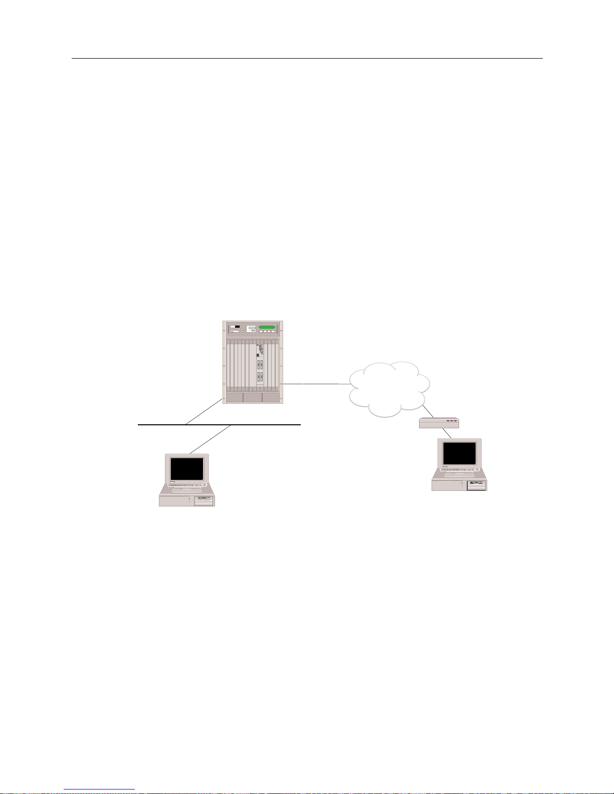
USER’S GUIDE
60 SmartSwitch Remote Access Module
If the re mote IP host CANNOT ping to the l ocal I P host, r efer to IP Routing Over a WAN Interface
Connection in the Problem Diagnosis chapter.
VERIFYING IP ROUTING OVER A WAN REMOTE LAN INTERFACE
To verif y that IP routing is properl y operation al over a WAN Remote LAN interface, a re mote IP
Host must b e operationa l and connect ed to the remote LAN. The remote b ridge device must be
operational and available to initiate connections. Also, a local IP host must be connected to the local
LAN port on the SmartSwitch Remote Access Module.
Below is an example of a configuration used to verify IP routing over a WAN Remote LAN
interfac e . I t uses IP ad dresses specific to the example. Substitu te the IP a dd resses of your network
when you perform the IP routing verification steps. It also uses the “ping” command. The “ping”
command sends a packet to a speci fied host, wa its for a respo nse, and reports success or f a ilure.
Substitute the equivalent command on your IP host.
The steps to verify the operation of IP routing over a WAN Remote LAN interface are:
1. Determine if a remote IP host can access the WAN Remote LAN interface of the SmartSwitch
Remote Access Module over th e WAN connection. On the remote IP host type:
ping 192.100.1.1
<return>
If the remote IP host successfully pings to the SmartSwitch Remote Access Module, then
contin u e wi t h the next ste p .
If the rem ote IP host CANNOT ping to the Smart S witch Remote Access Module, refer to IP
Routing over a WAN Remote LAN Interface Connection of the Problem Diagnosis chapter.
2. Determine if a r e mote IP host can access the LAN interface of the SmartSwitch Remote Acces s
Module ove r the WAN connec tion. On the remote IP host type:
ping 100.0.0.1
<return>
100.0.0.1
100.0.0.0
Host A
100.0.0.2
Host B
192.100.1.3
ISDN
Bridge
192.100.1.1
MMAC PLUS
Cabletron
Systems
MMAC-Plus with
SmartSWITCH
Remote Access Module
Page 61
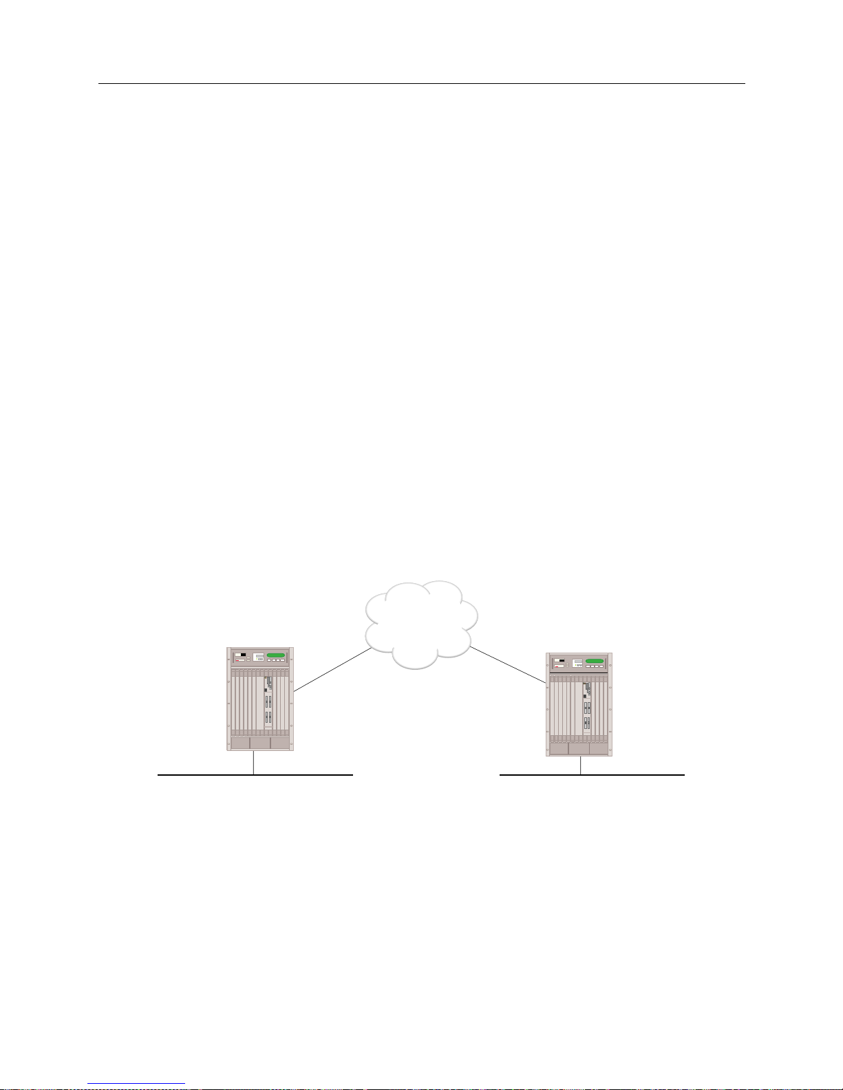
9W006 and 9W007 61
S
YSTEM VERIFICATION
Verifying IP Routing Over Interfaces
If the remote IP host successfully pings to the SmartSwitch Remote Access Module, then
contin u e wi t h the next ste p .
If the rem ote IP host CANNOT ping to the Smart S witch Remote Access Module, refer to IP
Routing over a WAN Remote LAN Interface Connection of the Problem Diagnosis chapter.
3. Determine if a remote IP host can access the local IP host through the SmartSwitch Remote
Access Mod ule over the WAN connection. On the re mote IP host type:
ping 100.0.0.2
<return>
If the rem ote IP host successfully pings to the local IP host, then I P r outing over the WAN
Remote LAN interface is operational. Repeat the above steps for each WAN Remote LAN
interface through which you wish to get access.
If the remote IP host CANNOT ping to the local IP host, refer to IP Rou t ing over a WAN Remote
LAN Interface Connection in the Problem Diagnosi s chapter.
VERIFYING IP ROUTING OVER A WAN UNNUMBERED INTERFACE
To verify that IP routing is properly operational over a WAN UnNumbered interface, the
SmartSwitch Remote Access Module must be operational and available to initiate conn e ctions.
Below is an example of a configuration used to verify IP routing over a WAN UnNumbered
interfac e . I t uses IP ad dresses specific to the example. Substitu te the IP a dd resses of your network
when you perform the IP routing verification steps. It also uses the “ping” command. The “ping”
command sends a packet to a speci fied host, wa its for a respo nse, and reports success or f a ilure.
The steps to verify the operation of IP routing over a WAN UnNumbered interface are:
1. Determine if SITE1 can access SITE2 over the WAN connection. On system A type:
ip ping 192.1.0.2
<return>
If the ping is successful, then continue with the next step.
If syste m A CANN OT ping to sy ste m B, refe r to IP Routing over a WAN UnNumbered Int erface
Connection in the Problem Diagnosis chapter.
100.0.0.1 192.1.0.2
ISDN
MMAC-Plus with
SmartSWITCH
Remote Access Module
MMAC PLUS
Cabletron
Systems
MMAC PLUS
Cabletron
Systems
MMAC-Plus with
SmartSWITCH
Remote Access Module
"SITE1"
"SITE2"
Page 62

USER’S GUIDE
62 SmartSwitch Remote Access Module
2. Determi ne if system B can access syst e m A over the WAN conne ction. On system B type:
ip ping 100.0.0.1
<return>
If the ping is successful, continue with the next step.
If the system B CANNOT ping to system A, refer to IP Routing over a W AN UnNumbered
Interface Connection in the Problem Di agno sis chapter.
VERIFYING IP RIP
The following sectio ns provide a method of verifying that IP RIP is initialized, and that it is
processing properly on LAN and WAN interfaces.
VERIFYING IP RIP IS INITIALIZED
Follow the steps below to verify that IP RIP processing is initialized.
1. Determi ne if IP RIP processing has been initiali zed by viewing the system messages. On th e
administration console type:
dr
<return>
2. The
dr
command d isplays t he cur rent system mes sages . Look for the follo wing I P RIP mes sage
among the syst e m message:
[IP RIP] RIP Protocol Initialization successful
If you see thi s IP RI P initialization message, the IP RIP has initialized su ccessfully.
If this IP RIP initialization message is NOT displayed, refer to IP RIP Initialization in the Probl e m
Diagnosis chapter.
VERIFYING IP RIP OUTPUT PROCESSING ON A LAN INTERFACE
To verify that IP RIP Output Processing (routes advertisement) is properly operational on a LAN
interface, the IP RIP processing must b e su ccessfully initialized. Also, a local IP host (router) mus t
be connected to the local LAN port on the system and capable of learning routes information via
RIP.
Below is an example of a c onfiguration used to ver ify IP RIP o utput process ing on a LAN interfa ce.
It uses IP addresses specific to the example. Substitute the IP addresses of your network when you
perform the verification steps. It also uses the
netstat
administration console command. The
netstat
command disp lays the IP rout ing table of the sys tem. Substit ute the equival ent command
on your IP host .
Page 63
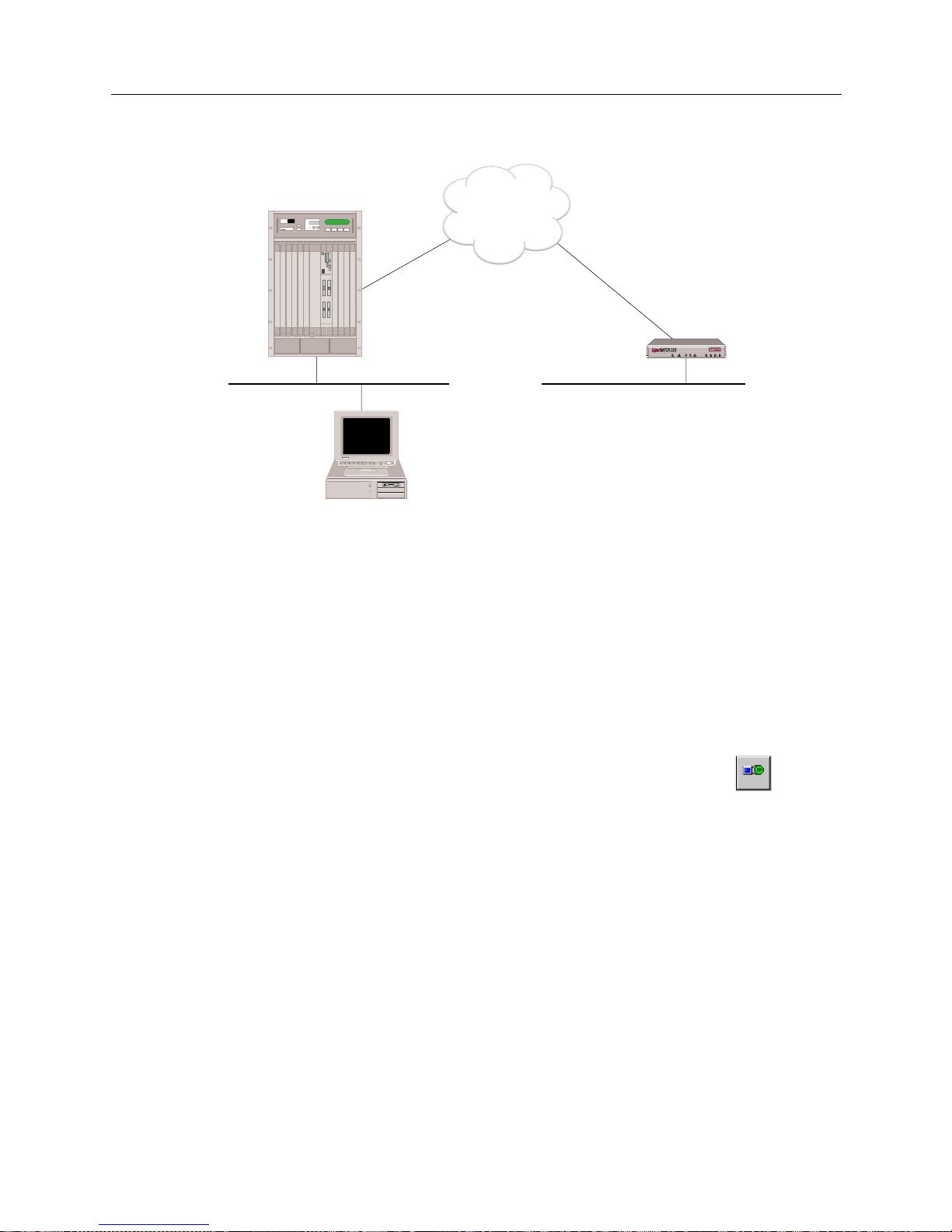
9W006 and 9W007 63
S
YSTEM VERIFICATION
Verifying IP RIP
To verify the op e ration of IP RIP output processi ng on a LAN interface:
1. Make sure that a static route to the network 192.1.1.0 is configured on SITE1. On SITE1’s
administration console type:
ip route
<return>
If the route to 192.1. 1.0 is displayed conti nue wit h the ne xt st ep.
If the route is NOT displayed, you will need to use SFVRA-CFG to add the static route. To do
this:
a. If it is not already running, start up SFVRA-CFG.
b. From the toolbar, select Functions, then IP Network Systems, or click on the icon .
c. Select SITE1 from di s p l a y e d li s t (you should have already co n f ig u r e d IP su b ne t and
network in te rface information for thi s site).
d. Click on the Static Routes tab.
e. Click on Add, then follow the onscreen in structions to add a static rou te .
f. Download the new configuration files to SITE1.
For more detailed instr uctio ns , refer to the follow ing sectio ns in the SFVRA Configuration
Manager User’s Guide:
• For static rou t e s : refer to Configuring IP Network System Static Routes in the Configuring IP
Network Information chapter.
"SITE1"
"SITE2"
100.0.0.1
ISDN
Host A
100.0.0.2
LAN 192.1.1.0
MMAC PLUS
Cabletron
Systems
MMAC-Plus with
SmartSWITCH
Remote Access Module
CSX150
Page 64
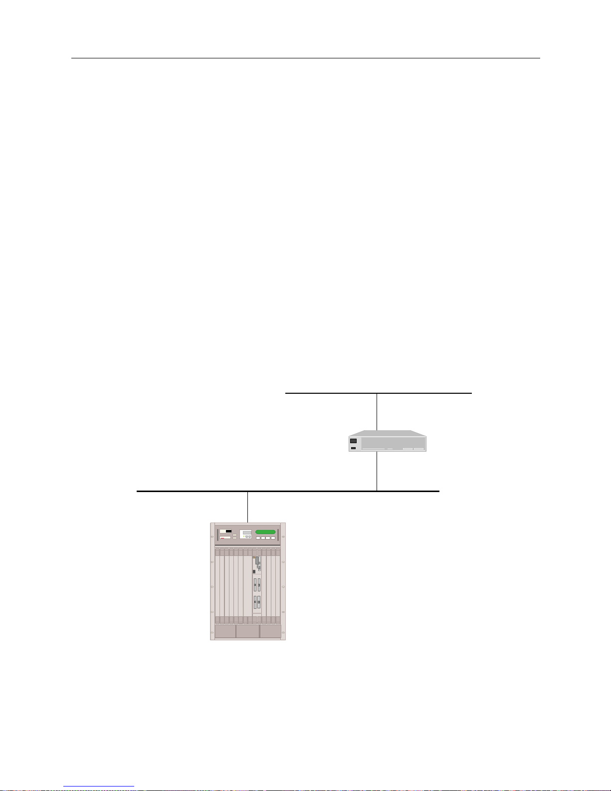
USER’S GUIDE
64 SmartSwitch Remote Access Module
• For downloading configur a tion files : refer to Dow n loadin g Co n figura t ion Upda t e s in the
Exporting Configuration Files chapter.
2. Determine if a local IP Hos t A has learned the route to 192.1.1.0 from System A. On IP Host A
type:
netstat -r
<return>
If the route to 192.1. 10 is displayed, the IP RIP output processi n g is operational.
If the route is NOT displayed, refer to IP RIP Output Processing on a LAN Interface in the Problem
Diagnosis chapter.
VERIFYING IP RIP INPUT PROCESSING ON A LAN INTERFACE
To verify that IP RI P Input Pr oces sin g (r oute s l ear ning) is pr oper ly oper ation al on a LAN int erfa ce,
IP RIP pr oce ssing must be succe ssfully initialize d. Also, a l ocal IP router must be connected to the
local LAN port on the system and capable of propagating routes information via RIP.
Below is an example of a configuratio n used to veri fy IP RIP i nput process ing on a LAN interface.
It uses IP addresses specified t o the example. Substitute t he IP addresses of your network when you
perform the verification steps. It also uses the
netstat
command. The
netstat
command
displays the IP routing table of the system. Substitute the equivalent command on your IP router.
LAN 131.1.0.0
Router 1
131.1.1.16
128.1.1.16
128.1.1.1
MMAC PLUS
Cabletron
Systems
MMAC-Plus with
SmartSWITCH
Remote Access Module
Page 65
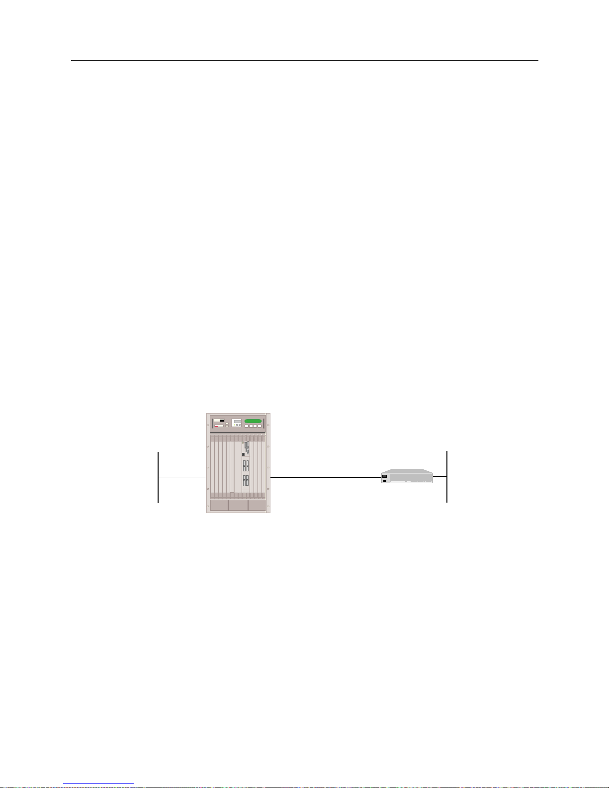
9W006 and 9W007 65
S
YSTEM VERIFICATION
Verifying IP RIP
To verify the op e ration of IP RIP input processin g on a LAN interface:
1. Determi ne if the SmartSwitch Remote Access Module has learned the route to 131.1.0.0 from
Router 1. On the administration console type:
ip route
<return>
If the f ollo wing ro ute en try is displ aye d am ong ot her rout e e ntr ie s, t h e IP RI P i nput p roce ssi ng
is operational. The ‘P’ (Protocol) field sh ould have ‘R’, which indic ates that the entry was
learned via RIP.
Destination Subnet-Mask Next Hop Mtr T/P TTL IF AGE
131.1.0.0 255.255.0.0 128.1.1.16 1 R/R 999 n nnn
2. If the route is NOT displayed, refer to IP RIP Input Processing on a LAN Interface in the Problem
Diagnosis chapter.
VERIFYING IP RIP OUTPUT PROCESSING ON A WAN INTERFACE
To verify that IP RIP Output Process ing (r outes advertisement) is properly operational on a WAN
interface, the IP RIP processing must be successfully initialized.
Below is an examp le of a confi gurati on use d to ver ify I P RIP out put pr ocessin g on a WAN inte rface.
It uses IP addresses specific to the example. Substitute the IP addresses of your network when you
perform the verification steps. It also uses the
show ip route
command. The
show ip route
command is used by a specific router to display the IP routing table. Substitute the equivalent
command for your IP router.
The steps to verify the operation of IP RIP output processing on a WAN interface ar e:
1. Make sure that a dedicated connection between system and Router is up and operational. On
the system’s administration console:
Type:
cs
<return>
If the conne ction to Router is displaye d, the continue with the next step.
2. Determine if Router has le arned the route to 192.1.1.0 from the system. On the Route r:
Type:
show ip route
<return>
If the route to 192.1. 1.0 is displayed, the IP RIP output processing is operational .
If the route is NOT displayed, refer to IP RIP Output Processing on a WAN Interface in the Problem
Diagnosis chapter.
Dedicated Connection
Router
192.1.1.1
100.1.1.1
100.1.1.2
192.1.2.1
MMAC PLUS
Cabletron
Systems
MMAC-Plus with
SmartSWITCH
Remote Access Module
Page 66

USER’S GUIDE
66 SmartSwitch Remote Access Module
VERIFY IP RIP INPUT PROCESSING OPERATIONAL ON A WAN INTERFACE
To verify that IP RIP Input Proces sing (r outes l earning ) is pr operl y operati onal on a WAN interfa ce,
the IP RIP processing must be successfully init ializ ed.
The same example that is used in the previous section is used to verify IP RIP input processing on
a WAN interface.
To verif y the op e ration of IP RIP Input proce ssing on a WAN interface:
1. Make sure that a dedicated connection between system and Router is up and operational. On
the Smart Switch Remote Access Module administration console:
Type:
cs
<return>
If the conne ction to Router is displaye d, the continue with the next step.
2. Determine if system has learned the route to 192.1.2.0 from the Router. On the SmartSwitch
Remote Access Module administration console:
Type:
ip route
<return>
If the route to 192.1. 2.0 is displayed, the IP RIP input pro cessing is operational.
If the route is N OT displayed, refer to IP RIP Input Processing on a WAN Interfa ce in the Problem
Diagnosis chapter.
VERIFYING IPX ROUTER IS INITIALIZED
To verif y that the IPX Routing option has initial ized properly.
1. Determine if IPX routing has been initialized on the SmartSwitch Remote Access Module by
viewing the system messages. To display the messages enter the following console command:
dr
<return>
2. Look for the following IPX message among the system message s:
[IPX] IPX router is initialized successfully
Also, for each IPX interface that has been configured, the following interface initialization
mess a g e should be d isplaye d am ong the system m e ss a g e s .
[IPX] Network initialized successfully on xxxxxxxx:xxxxxxxxxxxx
Note: Other messag e s may also be displaye d with the IPX rout e r initialization messages.
If you see these IPX router initialization messages, the IPX router is initialized.
If these IPX router initialization messages are NOT displayed, refer to IPX Ro ut ing Init iali za tio n
in the Problem Diagnosis chapter.
Page 67
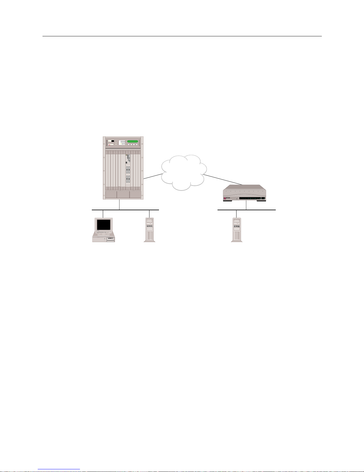
9W006 and 9W007 67
S
YSTEM VERIFICATION
Verifying IPX Routing is Operational
VERIFYING IPX ROUTING IS OPER ATIONAL
To verify that IPX routing feature is properly operational, a local NetWare client, a local NetWare
server and a remote NetWare server must be operational.
The following graphic illustrates an example network we will use to describe how to verify that IPX
routing is operational. It uses IPX network addresses specific to the example. Substitute the IPX
network numbers of your network w hen you perform the ver ification steps. The ex ample al so uses
NetWare commands av ailable for th e Windows 95 workstation. Substitute the equivalent
commands on your NetWare client.
VERIFYING IPX ROUTING OVER A LAN CONNECTION
To verify the operation of IPX Routing over a LAN connection:
1. Determine if SITE1 can access the local NetWare Server “local.” On SITE1’s administration
console type :
ipx diag cc:1 <return>
Note: Node address 1 is used by the NetWare servers as par t of their inter nal address.
2. If the system displays a re sp onse to the
ipx diag
command s imilar to :
received 3 components from cc:1
then IPX routing over that LAN port is operational.
If this message IS NOT displayed, then IPX routing over the LAN connection is not operational.
Refer to IPX Routing over the LAN Connection in the Problem Diagnosis chapter.
ISDN
CSX1200
Network AA
Network BB
NetWare
Client A
NetWare
Server
"local"
NetWare
Server
"remote"
Internal
Network CC
Internal
Network DD
POWER
SERVICE
TX
RX
10BASE - T
LAN B-CHANNELS E1 ONLY
B2 B4
B6 B8
B26 B28
B22 B24
B18 B20
B14 B16
B10 B12
B30 L1
B1 B3
B5 B7
B25 B27
B21 B23
B17 B19
B13 B15
B9 B11
B29 B31
E1
D
T1
D
MMAC PLUS
Cabletron
Systems
MMAC-Plus with
SmartSWITCH
Remote Access Module
"SITE1"
"SITE2"
Page 68

USER’S GUIDE
68 SmartSwitch Remote Access Module
VERIFYING AN IPX REMOTE LAN CONNECTION
To verify that IPX routing is proper l y oper atin g ov er a WAN Remote LAN interface, a remote IPX
router (in our example this is SITE1) must be operational and connected to the Remote LAN. The
remote bridge device (in our example, this is SITE2) must be operational and available to initiate
connections.
1. From the router (SITE1), verify that the IPX Remote LAN interface has initialized. On the
router’s administration console type:
dr
You should see messages stating that the IPX network has initialized successfully on xxxx.
Verify that “xxxx” is the network number of the Re mote LAN.
2. Determine the router’s (SITE1) MAC address. From the router, issue the command:
ver
3. From the remote bridge (SITE2), attempt to acce ss the IPX route r b y issuing the fo llowing
administration console command:
ipx diag xxxx:yyyyyyyyyyyy
where: xxxx is the IPX Network Numb e r
yyyyyyyyyyyy is the router’s MAC address
4. Verify the call has come up. From the router side (SITE1), issue the following administration
console command to display the monitor connections screen:
mc
If the call is displayed on the monitor co nne ctions screen, the IPX Remote LAN interface is
operational. If the call is not displayed, refer to IPX Routing over the Remote LAN Connection in
the Problem Diagnosis chapter.
VERIFYING IPX ROUTING OVER A WAN CONNECTIO N
To verify the operation of IPX Routing over a WAN connection:
1. Determine if NetWare Clie nt A can see the remote NetWare Server “remote.” To do thi s,
activate NetWare Client A’s desktop network neighborhood feature. Then check to see if
“remote” is included in Client A’s network neighborhood.
2. If “remote” is included in Client A’s network neighborhood, them IPX over the WAN
connection is operational. If it does not appear in the network neighborhood, then IPX over the
WAN connection is not operational. Refer to IPX Routing Over the WAN Connection in the
Problem Diagnosis chapter.
Page 69

9W006 and 9W007 69
S
YSTEM VERIFICATION
Verifying the AppleTalk Routing Feature
VERIFYING TRIGGERED RIP/SAP
Verify whether or not tr ig g e r e d RI P/SAP h a s st a r t e d and is op er a ti o n a l :
1. Determine if triggered RIP/SAP has started by viewing the system messages. To display the
messages, enter the following console command:
dr <RET>
2. Look for following message among the system mes sages:
Starting Triggered RIP/SAP for <WAN Peer>
3. If this message is displayed, contin ue check to see if Trigger ed RIP /SAP is op erationa l. If
message is not displayed , refer to Triggered RIP/SAP Start Up.
4. Determine if triggered RIP is operational. On the administration console, type:
ipx trigrip stats
5. Examine statis ti cs for activity. Refer to Triggered RIP Statistics for possible statistics and their
descriptions.
6. Create a change in the route (for example, shut down a server). Again examine statistics (
ipx
trigrip stats)
to verify the change is propagated to other side.
7. If statistics do not reflect chan ge, refer to Triggered RIP/SAP Operation.
8. Repeat process (beginning at step 4) for SAP, but substitute the following console command:
ipx trigsap stats
VERIFYING THE APPLETALK ROUTING FEATURE
VERIFYING APPLETALK ROUTING IS INITIALIZED
1. Determine if AppleTalk routing has been initialized on the SmartSwitch Remote Access
Module by viewing the system messages. To view the system messages, enter the following
console command:
dr
2. Look for the following message among the system messages:
AppleTalk routing initialized successfully
3. For the AppleTalk port that has been configured, the following port initialization message
should be disp layed among the system messages:
AppleTalk successfully initialized on <port-type> with address
<net.node>
Note: <port-type> is either LAN port 1, LAN port 2 or WAN.
<net.node> is the AppleTalk address assigned to this port.
4. If you see these AppleTalk routing initialization messages, then the AppleTalk routing has
initialized properly .
Page 70
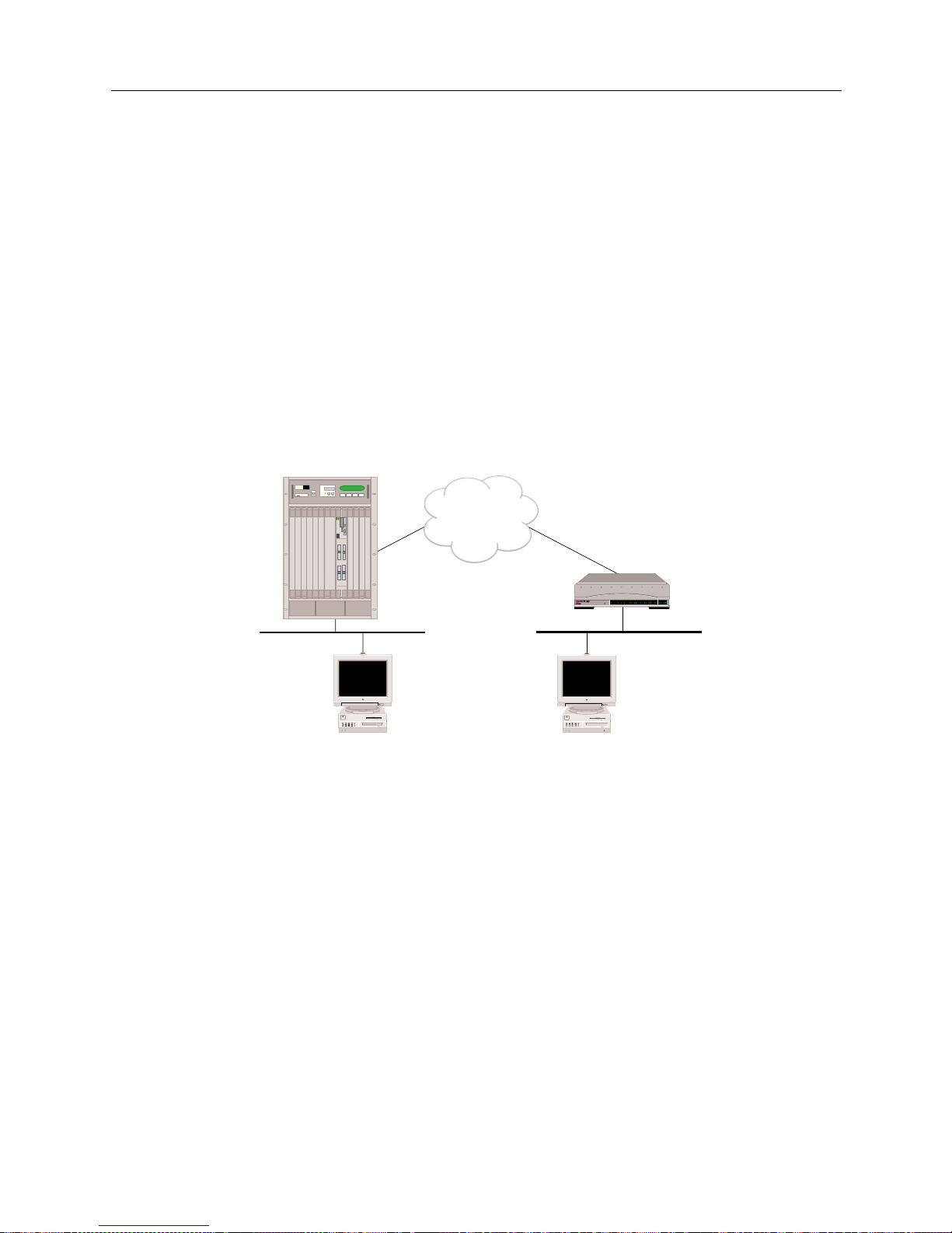
USER’S GUIDE
70 SmartSwitch Remote Access Module
If these messages are NOT displayed, refer to AppleTalk Routing I nitiali zation in the Problem
Diagnosis chapter.
VERIFYING APPLETALK ROUTING IS OPERATIONAL
To verify that AppleTalk ro utin g is properly operational, a remote Macintosh must be operati onal
and available to initiate WAN connections via a remote AppleTalk router device. Also, a local
Macintosh device must be connected t o the local LAN por t on the SmartSwitch Remote Access
Module.
Below is an example of a configuration used to verify AppleTalk Routing operation. It uses
AppleTalk addresses, zones and resource names specific to the example. Substitute those of your
network when you perform the AppleTalk Routing feature verification steps.
POWER
SERVICE
TX
RX
10BASE - T
LAN B-CHANNELS E1 ONLY
B2 B4
B6 B8
B26 B28
B22 B24
B18 B20
B14 B16
B10 B12
B30 L1
B1 B3
B5 B7
B25 B27
B21 B23
B17 B19
B13 B15
B9 B11
B29 B31
E1
D
T1
D
ISDN
CSX1200
"Site2"
Net Range: 10-11
Zone: Left Zone
Net Range: 20-21
Zone: Right Zone
Local Mac Remote Mac
MMAC PLUS
Cabletron
Systems
MMAC-Plus with
SmartSWITCH
Remote Access Module
"Site 1"
Page 71
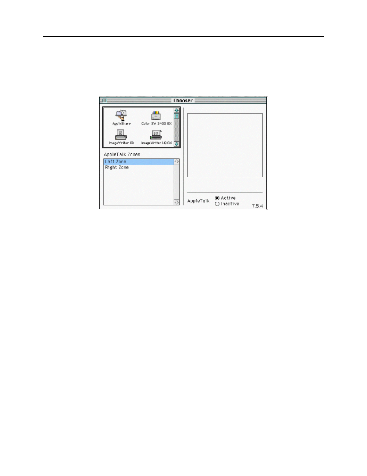
9W006 and 9W007 71
S
YSTEM VERIFICATION
Verifying the AppleTalk Routing Feature
VERIFYING APPLETALK ROUTING OPERATIONAL OVER THE LAN CONNECTION
The steps to verify the operation of AppleTalk Routing feature over a LAN connection are:
1. Determine if the local Mac in tosh can see all zones. Bring up the Chooser on the Local Mac:
2. If a list of all zon e s (Left Zone and Right Zone) appear in the Chooser as shown above, then the
AppleTalk Routing over a LAN connection is operational. Continue with t he next step.
3. If all zone s are NOT displayed, then AppleTalk Rou ting over the LAN connection is not
operational. Refer to AppleTalk Rout ing Operation over the LAN Connection in the Problem
Diagnosis chapter.
V
ERIFYING APPLETALK ROUTING OPERATION OVER A WAN CONNECTION
The steps to verify the operation of AppleTalk Routing feature over a WAN connection are:
1. Determi ne i f the Loca l Mac can ac ces s th e Remo te M ac. On the Local Mac , in the Ch oose r, pi ck
AppleShare on Right Zone:
Page 72
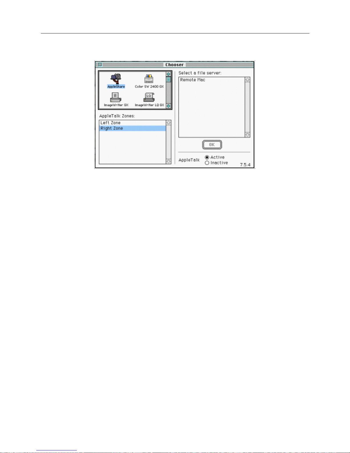
USER’S GUIDE
72 SmartSwitch Remote Access Module
2. If Remote Mac appears in Se lec t a file server: box, then AppleTalk Routing over the WAN
connection is operational.
3. If Remote Mac IS NOT displayed, then AppleTalk Routing feature over the WAN connection
is not operational. Refer to AppleTalk Routing Operation Over the WAN Connection in the Problem
Diagnosis chapter.
VERIFYING SNMP IS OPER ATION AL
1. To verify that the SNMP feature is operational, enter the
snmp stats
command at the
administration console. If the statistics display appears, the SNMP subsystem should be fully
operational. If the following message is displayed, SNMP is not operational:
SNMP is not enabled
If the preceding message is displayed, refer to SNMP in the Problem Diagnosis chapter for
possible actions you may take to make the SNMP feature operational.
2. To verify that the MIB objects can be retrieved via the SNMP get command, begin by making
sure that the latest vers io n of the ent erpr i se MIB (t he ih_mi b.a sn fil e) ha s been com pi led at th e
desire d SNMP network management stati on(s). Once the new version of the MIB is compile d,
you can issue the SNMP get command.
3. To veri fy the Sma rtSwitc h Remot e Acces s Module SN MP Agent i s retur ning the co rrect values ,
it is possi bl e to comp are the val ues of th e MIB o bject s ret ri ev ed vi a the S NMP get co mmand to
the output a vai lable via various syst e m administra tion consol e a nd dy namic management
commands. For example, the
isdn usage
console command displays B-channel information.
This information corresponds to the MIB isdnUsage M onitor group objects, a subset of t he
ihSystemMonitor group. The
dr
console command will return output that contains
information that corresponds to the MIB ihStatusReport table. Other console commands that
will output information that includes values that correspond to MIB objects are
ds, udp stats
,
ip stats,
and
snmp stats.
Page 73
9W006 and 9W007 73
S
YSTEM VERIFICATION
Verifying the Dial Out Feature
VERIFYING THE DIAL OUT FEATURE
To perf orm the Dial Out verification f or a remote device, you need to know the configured device
name associated with the device ’s device table entry. Note that the device name i s case sensitive.
1. The following administrativ e command i s used to v erify that the Di al Out f eature is oper ational
to a spec if i c re m o te d e v i ce:
call device <device name>
For example, to verify that the Dial Out featur e is operational for remote devic e with fred as the
configured device na me , you wo ul d ent e r
call device fred
at the syste m prompt.
2. A message will be displayed indicating whether or not the call was made successfully. Refer to
Dial Out in the Problem Diagnosis chapter if the call was not made su cce ssfully.
VERIFYING COMPRES SION IS OPERATIONAL
1. Make sure compression is enabled on a system-wide basis.
2. Cause a call to be establish ed with a dev ice for which per -dev ice co m pres sion is enabled .
3. To veri fy th at comp ress ion is i n e ffe ct wi th th e d evi ce , is sue the
cmp stats <devicename>
console command while the connection is in place. If compression is in effect, this command
will display the current compression counters and ratios. If compression is not in effect, the
comm an d wil l ret u r n an in dication th a t the de v ice i s a non- compre ss e d co n ne ction. If
compression is not in effect, refer to Comp ression in the Problem Diagnosis chapter.
VERIFYING RESERVED BANDWIDTH IS OPERATIONAL
1. Configure several different combinations of lines and devices.
2. Attempt outbound and inbound calls.
3. Verify the proper success and reject of each.
If there is a problem, check the configuration of the profiles and how they are assigned to each
device. Use SFVRA -CFG to check the profile co nfigu ra tion s. To do this:
a. If it is not already running, start up SFVRA-CFG.
b. From the toolbar, select Functions then select Sites, or click the icon.
c. Select a site from the displ ay e d list.
d. Click on the Systems tab.
e. Click on Edit Systems Settings.
f. Click on the Circuit Groups tab.
g. Check the circuit group confi guration f o r this device. Make any necessary changes.
Page 74

USER’S GUIDE
74 SmartSwitch Remote Access Module
h. Repeat steps c through g for each additional site you want to chec k.
i. If you make any changes, you will need to download the new configuration files to the
effected sites.
For more detailed instr uctio ns , refer to the follow ing sec tions in the SFVRA Configuration
Manager User’s Guide:
• For profiles: ref er to Configuring the Site’s Systems in the Configuring Sites chapter.
• For downloading configur a tion files : refer to Dow n loadin g Co n figura t ion Upda t e s in the
Exporting Configuration Files chapter.
VERIFYING A SEM IPERMANENT CONNECTION
Follow the same procedure outlined in the dial out verification section. If you can successfully use
the call device command to call the device assigned to the semipermanent connection, then the
connection is working. If not, follow the instructions actions in the dial out verification section.
Page 75

P
ROBLEM DIAGNOSIS
OVERVIEW
This chapter, when used in conjunction with the System Ver ification chapter, helps diagnose and
correct problems encountered in the verification process.
During some of the diagnosis pr ocedures , we ask you to enter an admi nistratio n console comm and.
To enter these comma nds, y ou must hav e an acti ve admin istrat ion sess ion. If you nee d instruc tions
for starting an administration session, refer to Accessing the SmartSwitch Remote Access Module.
WAN ADAPTER
Problem:
The system doe s not display the WAN Adapter Initialization messages. Inste ad, the syst e m
displ a y s on e of the f ol lowing messa ge s:
Error mapping WAN adapter # into Host memory map
Type mismatch of configured & installed adapter #
Error initializing WAN card: #
Failure during static RAM test on adapter #
Error downloading operational software to adapter #
Error downloading bootstrap program to adapter #
Action:
1. Note the displayed e rror message. Restart the SmartSwitc h Remote Access Module, and
recheck for one of the above error messages.
2. If the error message is still displayed, contact Customer Support.
LAN ADAPTER
Problem:
The syst em does no t displa y the LA N Adapter Initial izatio n messag es. Inste ad, th e system displ ays
one of the fol lowing messages:
Invalid LAN Adapter identifier
LAN Adapter Command Timeout
LAN Adapter FIFO not empty, status = #
LAN Adapter LAN Controller error
LAN Adapter Response Timeout
MAC layer Bridge did not Initialize
[IP] Initialization failure
Action:
1. Note the displayed e rror message. Restart the SmartSwitc h Remote Access Module, and
recheck for one of the above error messages.
2. If the error message is still displayed, contact your distributor for hardware replacement.
Page 76

USER’S GUIDE
76 SmartSwitch Remote Access Module
BRIDGE INITIALIZATION
Problem:
The system does not display the following bridge initialization messages:
LAN Port <port #> is now in the LISTENING state
LAN Port <port #> is now in the LEARNING state
LAN Port <port #> is now in the FORWARDING state
Action:
1. Make sure the LAN Adapter has initialized correctly.
2. Using SFVRA-CFG, check the configuration to verify the bridge is enabled. To do this:
a. If it is not already running, start up SFVRA-CFG.
b. From the toolbar, select Functions then select Sites or click the icon.
c. From the displayed list, double click on the site in question.
d. Click on the Systems tab.
e. Select the system in questi on, then click on Edit System Settings.
f. Under Bridging information, check to make sure that a check appear s next to Enable
(bridging information is included under the Properties tab).
g. If you made a change, downl oad the new configurati on files to e ffected site.
For more detailed instr uctio ns , refer to the follow ing sec tions in the SFVRA Configuration
Manager User’s Guide:
• For enabling bridging: refer to Configuring the Site’s Systems in the Configuring Sites chapter.
• For downloading configur a tion files : refer to Dow n loadin g Co n figura t ion Upda t e s in the
Exporting Configuration Files chapter.
IP ROUTING INITIALIZATION
Problem:
The system does not display the expected IP routing initialization messages.
Action:
1. If you did not see the following IP message:
[IP] IP router is initialized successfully
Using SFVRA-CFG, check the configuration to verify that IP routing is enabled. To do this:
a. If it is not already running, start up SFVRA-CFG.
b. From the toolbar, select Functions then select Sites or click the icon.
Page 77
9W006 and 9W007 77
P
ROBLEM DIAGNOSIS
IP Routing Initialization
c. From the displayed list, double click on the site you are diagnosing.
d. Click on the Systems tab.
e. Select the system in questi on then click on Edit System Settings.
f. Under the IP information, check to make sure that a check appears next to Enable (IP
information is included under the Properties tab).
g. If you made a change, downl oad the new configurati on files to e ffected site.
For more detailed instr uctio ns , refer to the follow ing sec tions in the SFVRA Configuration
Manager User’s Guide:
• For enabling IP routing: refer to Configuring the Site’s Systems in the Configuring Sites
chapter.
• For downloading configur a tion files : refer to Dow n loadin g Co n figura t ion Upda t e s in the
Exporting Configuration Files chapter.
2. The failure to s ee the following IP message for each IP interface:
[IP] Network initialized successfully on ddd.ddd.ddd.ddd
indicates that you may have either not configured a needed interface or have incorrectly
configured an interface. Check the system’s IP network interface configuration using SFVRACFG. If there are any problems, make the necessary corrections. To do this:
a. If it is not already running, start up SFVRA-CFG.
b. From the toolbar, select Functions, then IP Network , then Systems, or c li ck o n the ic on.
c. Select the system’s site from displa y e d list.
d. Click on the Network Interface tab.
e. Add any missing interfaces and/or make any necessary corrections to existing interfaces.
f. If you made any changes, download the updated configuration files to the effected system.
For more detailed instr uctio ns , refer to the follow ing sec tions in the SFVRA Configuration
Manager User’s Guide:
• For network interfaces: refer to Configuring IP Network System Interfaces in the Configuring
IP Network Information chapter.
• For downloading updated configuration files: refer to Downloading Configuration Updates in
the Exporting Configura tion Files chapter.
Page 78

USER’S GUIDE
78 SmartSwitch Remote Access Module
WAN LINE AVAILABILITY
Problem:
The system does not display the WAN line availability messages. Instead, the system displays the
following message after the
status
console com man d i s issued:
Line (slot #, port #) down
Action:
1. Verify that the line is correctly attached to the proper system resource and port.
2. If the line was correctly attached in ac tion 1, try restarting the system.
3. If actions 1 an d 2 fail to correct the problem, call your ph one company (carr ier) to check the
statu s of th e l in e .
Problem:
The system does not display the WAN line availability messages. Instead, the system displays the
following message after the
status
console com man d i s issued:
Out Svc 1 (slot #, port #)
This means that Layer 1 cannot be established, most likely due to WAN cabling problems.
Action:
1. If the system has been operati onal for longer than 2 minutes, ve rify that the line is correctly
attached to the p rope r system resource and port. If not, wait for 2 minutes and check again for
the WAN line availability messages.
2. If using a NT1 or CSU, examine the local and network lights of the NT1 or CSU. If the local light
is on, try anot h er ca ble between the Smar tSw itch Remo te Ac ce ss Modul e and t he NT1 or CSU .
If the local light is not on, but the network error light is on, contact your line provider.
3. If the line was correctly attached i n action 1, turn the s ystem off, then on. If this fails to cor re ct
the problem, continue with the next step.
4. Refer t o the Ordering ISDN Service chapter. Compare the parameters with those required by the
PRI line provider. It is possible that there is a mismatch.
5. If the above ac tions fail to corre ct the problem , then call your phone compa ny (carri er) to check
the status of the line. If it is determined that t here is no problem with the line, contact Customer
Support.
Problem:
The system does not display the WAN line availability messages. Instead, the system displays the
following message after the
status
console com man d i s issued:
Out Svc (2, 3, 4, or 5) (slot #, port #)
These mean that Layer 2 cannot be established, most likely due to an invalid configuration.
Page 79
9W006 and 9W007 79
P
ROBLEM DIAGNOSIS
WAN Line Availability
Action:
1. If the system has been operati onal for longer than 2 minutes, ve rify that the line is correctly
attached to the p rope r system resource and port. If not, wait for 2 minutes and check again for
the WAN line availability messages.
2. If the line was correctly attached i n action 1, turn the s ystem off, then on. If this fails to cor re ct
the problem, continue with the next step.
3. For the “Out Svc2 (slot #, port #)” message with a Primary Rate line, call your line provider and
have the data link restarted.
4. For the “Out Svc3 (slot #, port #)” on an Auto TEI line, check configuration. Try reconfiguring
(using SFVRA-CFG) the line using non-auto TEI. To do this:
a. If it is not already running, start up SFVRA-CFG.
b. From the toolbar, select Functions, then select Circuits or click the icon.
c. From the displayed list, double click on the circuit (line) in question.
d. Click on the Data Link tab.
e. Change the TEI negotiation value from Auto to Non-Auto. Click OK, then click Close.
f. If you made any changes to the configuration, download the new configuration files to
effected site.
For more detailed instr uctio ns , refer to the follow ing sec tions in the SFVRA Configuration
Manager User’s Guide:
• For data l ink s : re f e r to Configuring Circuit Data Links in the Configuring Circuits ch apt e r.
• For downloading configur a tion files : refer to Dow n loadin g Co n figura t ion Upda t e s in the
Exporting Configuration Files chapter.
5. If the above ac tions fail to corre ct the problem , then call your phone compa ny (carri er) to check
the status of the line. If it is determined that t here is no problem with the line, contact Customer
Support.
Problem:
A WAN line is unavailable, and the follo w ing two messag es are displa yed toget he r (to disp lay
messages, issue the
dr
console command):
WAN card in slot <slot #> signals it is operational
Abnormal response rcvd: state=-1 msg=73 reason=6 cc state=-1
Action:
1. Check the configuration. Verify that all lines are configured with corresponding data links. If
this is not the case, add data links to all configured lines using SFVRA-CFG.To do this:
a. If it is not already running, start up SFVRA-CFG.
b. From the toolbar, select Functions, then select Circuits or click the icon.
Page 80

USER’S GUIDE
80 SmartSwitch Remote Access Module
c. From the displayed list, double click on a circuit (line).
d. Click on the Data Link tab.
e. Check the data link information. Make corrections as required.
f. If you made any changes to the configuration, download the new configuration files to
effected site.
For more detailed instr uctio ns , refer to the follow ing sec tions in the SFVRA Configuration
Manager User’s Guide:
• For data l ink s : re f e r to Configuring Circuit Data Links in the Configuring Circuits ch apt e r.
• For downloading configur a tion files : refer to Dow n loadin g Co n figura t ion Upda t e s in the
Exporting Configuration Files chapter.
DEDICATED CONNECTIONS
Problem:
A dedicated connection is not fu nctioning.
Action:
If the dedi cated connection is not up, this usuall y indicates t hat the device cou ld not be valid a ted
for some reason. Check the configuration for the device that will be using the dedicated connection,
and make any necessary c orrections.
REMOTE DEVICE CONNECTIVITY
Problem:
A remote device is not able to connect to the SmartSwitch Remote Access Module.
Set-up:
The system software should be up and running. (At the administrat ion console: if y ou are in the
Connection Monitor window, exit to the “[System Name] >” prompt.)
1. Ena b le the call tra ce me s s ages with the
trace on
console command.
2. Erase the current system messages using the
er
console command.
3. In a controlled manner , initiate an ISDN connecti on from the re mote device.
Action:
1. After a connection ha s b e e n initiated, view the syste m me ssages (display system messages by
issuing the
dr
console comman d). Look for the following call request messages among the
system messages:
In - INCOMING CALL Call Id=<call Id> Slot =<slot #> Port=<port #> Chans=<bearer
channe l map > Ce s= <comm endpo in t su ffix> Rate= <d at a ra te>
Page 81

9W006 and 9W007 81
P
ROBLEM DIAGNOSIS
Remote Device Connectivity
Out - CONNECT Call Id=<call Id> Slot=<slot #> Port=<port #> Chans=<bearer
channel map> Ces=<communication endpoint suffix> ConnId=<connect Id>
In - CONNECT Call Id=<call Id> Slot=<slot#> Port=<port #> Chans=<bearer channel
map> Ces=<communication endpoint suffix> ConnId=<connect Id>
If the system reports these messages, then continue with the next step.
If the syst e m does not report these messages, the remote device is not correctly connecting to
the system. Check and verify the configuration of the remote d e vice.
2. If the system displays the following message among the system messages (display system
messages by issuing the
dr
console command),
Security Rejection-Invalid Calling Line Id - <#>
the network is indicating a calling line ident ifier tha t is not configured for any valid devic e in
the system Device list. The number “#” indicates the actual number pr esented by the network.
3. For Re mote Bri dg e De vices:
If the syst e m disp lays the following messages among the system mes sages,
Security Rejection - Caller did not negotiate security
Security Rejection - No Bridge Address given by caller
Security Rejection - Unknown Calling Bridge
Security Rejection - No Password given by caller
Security Rejection - Invalid Password given
Security Rejection - HDLC not supported by the caller
review the system configu ra t i o n fo r the remote device. Yo u can also refer to the System
Messages chapter for the message meanings and the appropriate actions to be taken.
4. For IP Host Devices:
If the syst e m disp lays the following messages among the system mes sages:
IP Call Dropped: ID_RSP was not received from remote
IP Call Dropped: XID was not received from remote
IP Security Rejection - Digit string wrong length
IP Security Rejection - Invalid Security ID <Id string>
Review the system configuration for the remote device. You can also refer to th e System
Messages chapter for the message meanings and the appropriate actions to be taken. The first
two messages indicate that the system did not receive the required protocol data. The secon d
two message s indicate th at the security configuration is inc orrect.
5. For PPP Devices:
If the system displays any error or warning messages that begin with the following prefixes :
[PAP].....
[CHAP].....
[AUTH].....
There prob ably is an error in the remote device configuration. Review your remote de vice
configuration. You can also refer to the System Messages chapter for t he message meanings an d
the appropriate action s to b e ta ken.
Page 82
USER’S GUIDE
82 SmartSwitch Remote Access Module
LAN ATTACHMENT
Problem:
The LA N T E S T co m m a nd displ ays the fol lowing me ssage:
LAN port 1 Transmit was not successful
Action:
1. Check to see if the Ethernet LAN is properly connected to the SmartSwitch Remote Access
Module.
2. Check to see if the Ethernet LAN is properly terminated.
(Test: Can an y other machine transmit data successfull y onto this LAN?)
3. If the problem is still not resol ved, conta ct Customer Support.
IP ROUTING OVER INTERFACE CONNECTIONS
This section provides diagnostic information for IP routing over various interface connections.
IP ROUTING OVER THE LAN INTERFACE CONNECTION
Problem:
The system does not display the correct message after the ping command. Instead, the system
displays the followin g message:
No response from <ip-address>
Action:
1. Verify that the routing entry for the destination network exists by entering the following
administrative console command:
iproute <ip-address>
If the co mma nd returns “No route is available for <ip-address>“, the routing entry
does not exist. To correct, add the routing entry using SFVRA-CFG. To do this:
a. If it is not already running, start up SFVRA-CFG.
b. From the toolbar, select Functions, then IP Network , then Systems, or c li ck o n the ic on.
c. Select the system’s site from di splay ed li st (you sh ould ha ve alread y con fig ured IP su bnet
and network interface information for this site ) .
d. Click on the Static Routes tab.
e. Click on Add, then follow the onscreen in structions to add a static rou te .
f. Download the new conf igura tion file s to the site.
For more detailed instr uctio ns , refer to the follow ing sectio ns in the SFVRA Configuration
Manager User’s Guide:
Page 83
9W006 and 9W007 83
P
ROBLEM DIAGNOSIS
IP Routing Over Interface Connections
• For static rou t e s : refer to Configuring IP Network System Static Routes in the Configuring IP
Network Information chapter.
• For downloading configur a tion files : refer to Dow n loadin g Co n figura t ion Upda t e s in the
Exporting Configuration Files chapter.
2. Check that the system and the specified Host both have the same Subnet mask and Sub
network numb er fo r that IP addr ess using SF VRA-CFG. Cor rect th e Host c onf igur atio n, or t he
system configuration as required. To do this:
a. If it is not already running, start up SFVRA-CFG.
b. From the toolbar, select Functions then click on IP Network, then on Subnets, or click
on the toolbar.
c. Doub le cl ick on the p a rt i cu la r subnet th a t a p p li e s to th e system .
d. Check the subnet’s mask and network number. Compare the values to the host’s
configuration.
If you chan ge the sy stem’s mask and/or subn etwor k number ins tead of t he host’ s, you will
need to configure a new subnet, and associate the syst e m with the new subne t. This is
because you cannot change these values for the subnet once it has been configured. Refer
to the SFVRA-CFG documentation if you need to do this.
For more detailed instr uctio ns , refer to the follow ing sectio ns in the SFVRA Configuration
Manager User’s Guide:
• For static rou t e s : refer to Configuring IP Network Subnet Information in the Configuring IP
Network Information chapter.
• For downloading updated configuration files: refer to Downloading Configuration Updates in
the Exporting Configura tion Files chapter.
3. Verify that the ARP entry for the specified IP address exists. As required, ping from the IP Host
so that the ARP en try is updated . Use the
ip arp
console command to look at the ARP cache
entries. If the ARP cache entry for t he Host does not exist, verify that the Host is o perational
and that the SmartSwitch Remote Access Module and the Host are both physically connected
to the same LAN segment.
4. If the ARP cache entry exists for the Host, check that the IP Host has the same encapsulation
type as the SmartSwitch Remote Access Module. The system can receive and recognize either
Ethernet or SNAP type encapsulations. Correct th e IP Host or system configuration (through
SFVRA-CFG) for encapsulation type. To do this f or SmartSwitch Remote Access Module:
a. If it is not already running, start up SFVRA-CFG.
b. From the toolbar, select Functions then click on IP Network, then on Subnets, or click
on the toolbar.
c. Doub le cl ick on the p a rt i cu la r subnet th a t a p p li e s to th e system .
Page 84
USER’S GUIDE
84 SmartSwitch Remote Access Module
d. Click on the Network Interfaces tab.
e. Double click on the interface in question.
f. Click on the Expert Properties tab.
g. Check t he value for the Packet Encapsulation type. Compare the value t o the host’s value.
If they are not the same, change the value to make them the same.
h. If you made any changes, download the new configuration files to the site.
For more detailed instr uctio ns , refer to the follow ing sec tions in the SFVRA Configuration
Manager User’s Guide:
• For static rou t e s : refer to Configuring IP Network Subnet Interfaces in the Configurin g IP
Network Information chapter.
• For downloading updated configuration files: refer to Downloading Configuration Updates in
the Exporting Configura tion Files chapter.
5. Try to ping the Host from another device on the LAN. If this is also unsu ccessful, this may
indicate a problem with the Host.
6. Verify that the hardware address (MAC addre ss) f or the IP Host i n the sy stem’s ARP cache is
correct. If it is not correct, verify the configuration in the IP Host.
IP ROUTING OVER A WAN INTERFACE CONNECTION
Problem:
The remot e IP Host connected to a WAN interface does not re ceive a ping resp onse from the
SmartSwitch Remote Access Module WAN i nterface.
Action:
1. Verify that the WAN co nnection is up. Use the
mc
console comm and to displa y the Connect ion
Monitor d isplay. Check for the connection. If the conne ction i s up, con tinue with the next step.
If the conne ction is not up, refer to the s e ction titled Remote Device Connectivity.
2. Verify that the WAN int erface is properly initialized. Use SFVRA-CFG to check for the proper
WAN interface (refer to page 77 for instructions). If it exists, continue with the next step.
If the proper WAN interface does not exist, make corrections to the system configuration using
SFVRA-CFG.
3. Check that th e IP address conf igure d for the IP Host devi ce matches th e address con figur ed on
the IP Host device. Make corrections to the SmartSwitch Remote Access Module’s
configuration (using SFVRA-CFG), or to the IP Host’s configuration, as required. To do this:
a. If it is not already running, start up SFVRA-CFG.
b. From the toolbar, select Functions, then IP Network , then Systems, or c li ck o n the ic on.
Page 85

9W006 and 9W007 85
P
ROBLEM DIAGNOSIS
IP Routing Over Interface Connections
c. Select t he IP H ost’s s i te fr om di spla yed list ( you sh ould have alr eady confi gured IP subn et
and network interface information for this site ) .
d. Click on the Network Interfaces tab.
e. On the resulting screen, check the IP Host’s IP address. Compare it to the address
configured on the IP host (for the IP host). If t hese are not th e same, make corrections where
necessary.
f. If you made a change using SFVRA-CFG, download the updated configuration files to the
site.
For more detailed instr uctio ns , refer to the follow ing sec tions in the SFVRA Configuration
Manager User’s Guide:
• For network interfaces: refer to Configuring IP Network System Interfaces in the Configuring
IP Network Information chapter.
• For downloading configur a tion files : refer to Dow n loadin g Co n figura t ion Upda t e s in the
Exporting Configuration Files chapter.
Problem:
The remote IP Host connec ted to a WAN int erface o n the SmartSwi tch Remot e Acc ess Modul e does
not receive a ping response from the LAN interface.
Action:
1. Verify th at the r emote I P Host can acces s the WAN i nterface of the SmartSw itch Remote Acces s
Module. I f t he re mote IP H ost acc ess es the WAN i nterf ace s ucc essf ully , th en co nt inue w i th the
next step.
If the remote I P Host is not able to acce ss the WAN interface, then refer to the preceding
problem and associated acti ons.
2. Verify that the LAN interface is properly configured by using SFVRA-CFG (refer to page 77 for
instructions). If the proper LAN interface exists, then continue with the next step.
If the proper LAN interface does not exist, use SFVRA-CFG to make the necessary correc tions.
3. Verify that the remote IP Host is initiati ng a call to the SmartSwitch Remote A ccess Module.
Since the LAN interface has an IP addres s assigned with a different network number than the
one for the remote IP Host, the remote IP Host may need a proper route entry for the local
network whe re the SmartSwitch Remote Access Module is locate d. Make corrections to the
remote IP Host configuration.
Problem:
The remote IP Host connec ted to a WAN int erface o n the SmartSwi tch Remot e Acc ess Modul e does
not receive a ping response from the local IP Host.
Action:
1. Verify th at th e r emot e IP Host c an ac cess the LA N inter fac e of t he SmartSw it ch Re mote Acces s
Module. If the remote IP Host accesses the LAN interface, then continue with the next step.
Page 86

USER’S GUIDE
86 SmartSwitch Remote Access Module
If the rem ote Host is unable to access the LAN interface, refer to the pre ceding problem and
associated actions.
2. Verify that the local IP Host h as the route entry f or the remot e network with the SmartSwitch
Remote Access Module as the next hop .
If the local IP Host has the proper route entry to the remote network, refer to Verify IP Routing
Over a LAN Connection in the System Verification chapter.
If the local IP Host does not have the proper route entry, mak e corrections to the local IP Host
configuration.
IP ROUTING OVER A WAN RLAN INTERFACE CONNECTION
Problem:
The remote IP Host connected to a WAN RLAN interface on th e SmartSwitch Remote Access
Module does not receive a ping response from the SmartSwitch Remote Access Module WAN
RLAN inte rface.
Action:
1. Verify that the WA N connec tion is up. Use the
mc
console com man d to display the Monitor
Connections screen. Check for the connection. If the connection is up, then continue with the
next step.
If the conne ction is not up, refer to Remote Device Connectivity.
2. Verify that the WAN RLAN interface is properly initialized. Use SFVRA-CFG to check for the
proper WAN RLAN interface (r efer to page 77 for instructions). If th e p roper WAN RLAN
interface exists, then continue with the next step.
If the proper interface does not exist, use SFVRA-CFG to make the necessary corrections.
3. Check that th e IP address conf igure d for the IP Host devi ce matches th e address con figur ed on
the IP Host device. Make corrections to the SmartSwitch Remote Access Module’s
config u ration (using SFVRA-CFG), or to the IP Host’s configuration, as required. To do this,
follow the instructions outlined on page 84.
Problem:
The remote IP Host connected to a WAN RLAN interface on th e SmartSwitch Remote Access
Module does not receive a ping response from the SmartSwitch Remote Access Module LAN
interface.
Action:
1. Verify th at the remot e IP Host can acces s the WAN RLA N interface of the Smar tSwitch Remote
Access Module. If this can be done successf ully, con tinu e with the next step.
If the remo te IP Host is not able to access the WAN RLAN interf ace, then re fer to the p recedin g
problem and action.
Page 87

9W006 and 9W007 87
P
ROBLEM DIAGNOSIS
IP Routing Over Interface Connections
2. Verify that the LAN interface is properly initialized. Use SFVRA-CFG (refer to page 77 for
instructions) to check for the proper LAN interfaceIf the proper i n ter f ace exists, then continue
with the next st e p .
If the proper interface does not exist, use SFVRA-CFG to make the necessary corrections.
3. Verify that the remote bridg e devic e is initiating a call to the Smar tSw itch Rem o te Ac cess
Module. Since th e Sm a rtSwitch Remo te Access Mo d ule LAN in t e rf a ce h a s a n IP a ddress
assigned with a different network number than the one for the remote IP Host, the remote IP
Host may need a proper route entry for th e local network where the SmartSwitch Remote
Access Mod ule is located . Make correc tions to the re mote IP Host configuration.
Problem:
The remote IP Host connected to a WAN RLAN interface on th e SmartSwitch Remote Access
Module does not receive a pi ng re sponse from the local IP Host.
Action:
1. Verify th at th e r emot e IP Host c an ac cess the LA N inter fac e of t he SmartSw it ch Re mote Acces s
Module. If it accesses the LAN interface, then continue with the next step.
If the rem ote Host is unable to access the LAN interface, refer to the pre ceding problem and
action.
2. Verify that the local IP Host h as the route entry f or the remot e network with the SmartSwitch
Remote Access Module as the next hop . If it does, refer to Verify IP Routing Over a LAN
Connection in the System Verification chapter.
If the local IP Host does not have the proper route entry, mak e corrections to the local IP Host
configuration.
IP ROUTING OVER A WAN UNNUMBERED INTERFACE CONNECTION
Problem:
The remo te router connec ted to a WAN UnNumber ed inter face on the Sma rtSwitc h Remote Access
Module does not receive a ping response from the SmartSwitch Remote Access Module LAN
interface.
Action:
1. Have the remote router ping itself using its LAN IP address.
2. Have the Smar tSwitch Remote Access Modul e pin g itself usin g its LAN IP address.
3. Have the router pin g the SmartSwitch Remote Acces s Module. If the p in g is unsuccessful:
• and no call is up, check the static route on the router
• and a call is up, check the static route on the SmartSwitch Remote Access Module (refer to
page 82 for instructions regarding getting to the IP static route information using SFVRA-
CFG).
Page 88
USER’S GUIDE
88 SmartSwitch Remote Access Module
IP RIP
This section provides guidance for diagnosing IP RIP operational problems.
IP RIP INITIALIZATION
Problem:
The SmartS witch Remote Access Module doe s not display the correct IP RIP Initiali zation
messa g e s. Instead, it displ a y s on e or more of the f ollowing messa ge :
[IP RIP] Initialization failed, unable to allocate buffers
[IP RIP] Unable to open RIP/UDP port 512
Action:
There is an unexpected condit ion present within the SmartSwitch Remote Access Modul e software.
Contact Cus tomer Support.
IP RIP OUTPUT PROCESSING ON A LAN INTERFACE
Problem:
The local IP Host does not display the correct route entry, for example, the IP Host does not seem
to be learn in g route information from th e SmartSwitch Remote Acces s Module via RIP.
Action:
1. Using SFVRA-CFG, verify that the IP RIP Send Control i s se t to a RIP version that the IP Host
can understand. To check the system’s IP RIP Send Control value
a. If it is not already running, start up SFVRA-CFG.
b. From the toolbar, select Functions, then IP Network , then Systems, or c li ck o n the ic on.
c. Select the system’s site from di splay ed li st (you sh ould ha ve alread y con fig ured IP su bnet
and network interface information for this site ) .
d. Click on the Network Interface tab.
e. Select the appropriate interface.
f. Click on the Expert Optio ns ta b .
g. Check to see that the value selected for RIP Send Control is set to the version the IP Host
can understand. If necessary, change the value.
h. If you made any changes to the configuration , download the updated config uration files to
the effected site.
For more detailed instr uctio ns , refer to the follow ing sec tions in the SFVRA Configuration
Manager User’s Guide:
• For network interfaces: refer to Configuring IP Network System Interfaces in the Configuring
IP Network Information chapter.
Page 89
9W006 and 9W007 89
P
ROBLEM DIAGNOSIS
IP RIP
• For downloading configur a tion files : refer to Dow n loadin g Co n figura t ion Upda t e s in the
Exporting Configuration Files chapter.
2. Enter the
ip rip stats
administrative console command. Look f o r the
IfStatSentResponses counter for the interface, which shows the number of RIP update
mess a g e s se nt on the interface.
If the counter is 0, enter the
ip rip send
administrative console command to force the RI P
update message to be sent im me diately.
3. Repeat step 2.
If the counter is still 0, there is an unexpected condit ion present with in the SmartSwit ch Remote
Access Mod ule software. Contact Customer Support.
4. If the RIP Send Control is set to “RIP Version 1” or “RIP Version 1 Com patibilit y, ” verify that
the transm it broadcast addr e ss on the inte rf ace is set to a proper address that the IP Host can
receive.
Change the value using SFVRA-CFG if the transmit broadcast address is not set properly. To
do this:
a. If it is not already running, start up SFVRA-CFG.
b. From the toolbar, select Functions, then IP Network , then Systems, or c li ck o n the ic on.
c. Select the system’s site from di splay ed li st (you sh ould ha ve alread y con fig ured IP su bnet
and network interface information for this site ) .
d. Click on the Network Interface tab.
e. Select the appropriate interface.
f. The Transm it Bro adc a st Add ress value is under Properties. Enter a correction if necessary.
g. If you made a change, download the updated configuration files to the effec ted system.
For more detailed instr uctio ns , refer to the follow ing sec tions in the SFVRA Configuration
Manager User’s Guide:
• For network interfaces: refer to Configuring IP Network System Interfaces in the Configuring
IP Network Information chapter.
• For downloading configur a tion files : refer to Dow n loadin g Co n figura t ion Upda t e s in the
Exporting Configuration Files chapter.
5. Check the IP Host and ensure that it is set up to lear n route information via RIP.
Page 90

USER’S GUIDE
90 SmartSwitch Remote Access Module
IP RIP INPUT PROCESSING ON A LAN INTERFACE
Problem:
The SmartSwitch Remote Access Module does not display the correct route entry, for example, the
module does not seem to be learning route information via RIP.
Action:
1. Verify th at the IP RIP Receive Control is s e t to the proper RIP version that the Router is using.
Refer to page 88 for instructions regarding check RIP versions.
2. Enter the
ip rip stats
administrative console command. Look f o r the counter
IfStatRcvResponses for the interface, which show the number of RIP update messages
receive d on the interface.
If the total number of t hese counters is 0, check the Ro uter to verify t hat it i s configured t o send
IP RIP update messages.
3. Also look for the IfStatRcvBadPackets and
IfStatRcvBadRoutes counters.
If these counters are not 0, there may b e some thing wrong with the Router .
If these counters are 0, there is an unexpected condition present within the SmartSwitch
Remote Access Module softwar e . Contact Customer Support .
IP RIP OUTPUT PROCESSING ON A WAN INTERFACE
Problem:
The Router does not display the correct route entry, i.e., the Router does not seem to be learning
route information from the SmartSwitch Remote Access Module system via RIP.
Action:
1. Verify that the IP RIP Send Contr ol is set to the pr op e r RI P ve rsion that the Router can
understand. Refer to page 88 for instructions regarding check RIP versions.
2. Enter the
ip rip interface
administrative console command. Look for the Broadcast
Address value. This is the IP address of the router that the RIP messages are sent to.
If the addre ss is not the correct address for the Router, correct the transmit broadc ast address
for the in terface using SFVRA-CFG. Ref e r to page 89 for instructions regarding checking the
address.
3. Enter the
ip rip stats
admini st rat ive c on so le co mmand . L oo k for th e IfStatSentResponses
counter for the interface, which shows the number of RIP update messages sent on the
interface.
If the counter is 0, enter the
ip rip send
administ rati ve co ns ole com mand to forc e th e RI P
update message to be sent im me diately.
4. Repeat step 3).
If the counter is still 0, there is an unexpected condit ion present with in the SmartSwit ch Remote
Access Mod ule software. Contact Customer Support.
Page 91

9W006 and 9W007 91
P
ROBLEM DIAGNOSIS
IPX Routing
5. Check the Rou te r and ensure th at it is set up to learn route information via RI P.
IP RIP INPUT PROCESSING ON A WAN INTERFACE
Problem:
The SmartS witch Remote Access Module system does not di sp lay the correct route entry, i.e. , the
system does not seem to be learning route information via RIP.
Action:
1. Verify that the IP RIP Receive Control is set t o the proper RIP version that the Router is using.
Refer to page 88 for instructions regarding check RIP versions.
2. Enter the
ip rip stats
administ rat ion con so le com mand. Look for th e IfStatRcvResponses
counter for the interface. This statistics is the number of RIP update messages received on the
interface.
If the total number of t hese counters is 0, check the Ro uter to verify t hat it i s configured t o send
IP RIP update messages.
3. Also look for the IfStatRcvBadPackets and IfStatRcvBadRoutes counte rs.
If these counters are not 0, there may b e some thing wrong with the Router .
If these counters are 0, there is an unexpected condition present within the SmartSwitch
Remote Access Module system software. Contact customer su p p ort.
IPX ROUTING
This section provides methods for diagnosing problems in the following areas of IPX routing:
• IPX routing initialization
• IPX routing over the LA N connection
• IPX routing over the RL AN connection
• IPX routing over the WA N connection
• triggered RIP/SAP start u p
• triggered RIP/SAP operation
IPX ROUTING INITIALIZATION
Problem:
The SmartSwi tch Remote Access Module do e s not display th e correct IPX Initialization messages.
Instead, it displays the following message (display messages by entering the
dr
console com mand) :
[IPX] Initialization failure
Action:
An internal error has occurred. Contact Customer Support
Page 92
USER’S GUIDE
92 SmartSwitch Remote Access Module
IPX ROUTING OVER THE LAN CONNECTION
Problem:
The SmartSwitch Remote Access Module does not display the correct message after issuing the
ipx
diag
or
ipx ping
command. I nstead, it displays the followin g message:
No response from <ipx-address>
Action:
1. Verify that the routing entry for the destination network exists by entering the following
console command:
ipx route
If the SmartSwi t ch Remote Ac ces s Modul e displ ays th e route to the dest i nati on, it knows ho w
to reach the local server’s internal network. Determine if this is a static route or a dynamic route
learned via RIP. The ou tp u t of an
ipx route
command contains a protocol (P) field for each
route entry, which indicate if it is static (L- locally configured) or dynamically learned via RIP
(R). If it is learned via RIP, then basic communication between the SmartSwitch Remote Access
Module and the local NetWare server is operational, and it is uncertain why the NetWare
server do es not respond to th e ping request. Contact Customer Support.
2. Using SFVRA- CF G , verify th at IPX RIP send an d rece ive cont rol is ena bled for the LAN
interface. To check the system’s IP X RIP send and receive control values:
a. If it is not already running, start up SFVRA-CFG.
b. From the toolbar, select Functions, then IPX Network, then Systems, or click the icon.
c. Select the system from di sp layed list.
d. Click on the Network Interface tab.
e. Select the appropriate interface.
f. Click on the Expert Optio ns ta b .
g. Check to see that RIP send control is set to send and RIP receive control is set to receive. If
they are not, change the values.
h. If you made any changes to the configuration , download the updated config uration files to
the effected site.
For more detailed instr uctio ns , refer to the follow ing sec tions in the SFVRA Configuration
Manager User’s Guide:
• For network interf aces: ref er to Configuring IPX Network System Interfaces in the Configuring
IPX Network Information chap ter.
• For downloading configur a tion files : refer to Dow n loadin g Co n figura t ion Upda t e s in the
Exporting Configuration Files chapter.
3. If the route does not exist, or the route is a static entry, then verify that the SmartSwitch Remote
Access Module and the local NetWare server are using the same packet encapsulation. To
check the type of encapsulation, use SFVRA-CFG. The packet en capsulation type is config ured
Page 93
9W006 and 9W007 93
P
ROBLEM DIAGNOSIS
IPX Routing
on the same Exp ert Op t io ns sc ree n desc ribe d in th e above action. If they are not using the same
encapsulation, then correct it either on the SmartSwitch Remote Access Module or the NetWare
server.
4. Verify that the SmartSwitch Remote Access Module and the NetWare server are using the same
external IPX network number for their mutual LAN (AA for this example). To check the
network numb e r th at the Smart Switch Remote Access Module is using, use SFVRA-CF G. If
they are not using the same external network number, then correct the problem. To check or
change the SmartSwitch Remote Access Module’s external network n umber:
a. It it is not already runn ing, start up SFVRA-CFG.
b. From the toolbar, select Functions, then IPX Network, then Systems, or click the icon.
c. Select the IPX segment in question fro m disp layed list.
d. Under the Properties tab, check th e segment’s External Network Number. M ake a change
if necessary.
e. If you made any changes to the configurat ion, download the update d configuration fi les to
the effected site.
For more detailed instructions, refer to the following sections in the SFVRA Configuration Manager
User’s Guide:
• For network inter fac es: r efe r t o Configuring IPX Network System Interfaces in the Configuring IPX
Network Information chapter.
• For downloading configur a tion files : refer to Dow n loadin g Co n figura t ion Upda t e s in the
Exporting Configuration Files chapter.
IPX ROUTING OVER THE REMOTE LAN CONNECTION
Problem:
The system does not display the IPX messages indicating successful initiation on Remote LAN
network.
Action:
Using SFVRA-CFG, check the IPX network interface configuration. To do this:
1. It it is not already runn ing, start up SFVRA-CFG.
2. From the tool bar, sel e ct Functio ns, then IPX Network, then Systems, or click the icon.
3. Select the sy stem from displayed list.
4. Click on the Network Interfaces tab.
5. Select the appropriat e inter face and check the i nterfac e confi guration f or possible erro rs. Make
corrections as needed.
Page 94

USER’S GUIDE
94 SmartSwitch Remote Access Module
6. If you made any changes to the configuration, download the updated configuration files to the
effected site.
For more detailed instructions, refer to the following sections in the SFVRA Configuration Manager
User’s Guide:
• For network inter fac es: r efe r t o Configuring IPX Network System Interfaces in the Configuring IPX
Network Information chapter.
• For downloading configur a tion files : refer to Dow n loadin g Co n figura t ion Upda t e s in the
Exporting Configuration Files chapter.
Problem:
Data is not forwarded from the remote bridge to the router over the Remote LAN interface.
Action:
Check the configuration:
1. Verify Remote LAN interface conf iguration. Refer to the above action for instructions
regarding checking an interface’s configuration.
2. Verify device configuration on remote bridge. Bridge devices should be configured to make
calls over the interface defined to go to the router.
Problem:
The router does not forward typical data (RIP, SAP, Type 20 packets) to the remote bridge.
Action:
1. Make sure a call is up. Remember, the router cannot forward data if there is no previous
connection (i.e., router currently does not support dial-out).
2. Check IPX device information on the rou ter side. Instructi ons for accessing the device ’s IPX
information are on page 93.
Problem:
Data is n ot r eceiv ed by a re mote clien t (or server ) on a Remote L AN netwo rk, bu t the cal l doe s come
up between the router and the remote bridge.
Action:
1. Double check and resolve any configuration/connection problems for the client (or server) to
the bridge on the Remote LAN. (Basically, elimina te the possibil ity of any LAN configu rati on
problems which are unrelated to the Remote LAN interface).
2. If you det e rmine the problem is relat e d to the Remote LAN, verify t he I P X Network Number
for the remote bridge in the router’s configuration (under bridging properties). Refer to page
93 for instructions on checking the IPX Network Number.
Page 95
9W006 and 9W007 95
P
ROBLEM DIAGNOSIS
IPX Routing
IPX ROUTING OVER THE WAN CONNECTION
Problem:
The remote NetWare server does not appear in the NetWare client’s network neighborhood.
Action:
1. Verify th at the SmartSwitch Remote Access Module has SAP process enabled. To do this:
a. If it is not already running, start up SFVRA-CFG.
b. From the toolbar, select Functions, then IPX Network, then Systems, or click on the
icon.
c. Select the system’s site from displayed list (you should have al ready configured IPX
segment in formati o n for this site).
d. Click on the Network Interface tab.
e. Select the appropriate interface.
f. Click on the Expert Optio ns ta b .
g. Check to see that the SAP Configuration value is set to Send.
h. If you made any changes to the configuration , download the updated config uration files to
the effected site.
For more detailed instr uctio ns , refer to the follow ing sec tions in the SFVRA Configuration
Manager User’s Guide:
• For network interf aces: ref er to Configuring IPX Network System Interfaces in the Configuring
IPX Network Information chap ter.
• For downloading configur a tion files : refer to Dow n loadin g Co n figura t ion Upda t e s in the
Exporting Configuration Files chapter.
TRIGGERED RIP/SAP START UP
Problem:
The SmartSwitch Remote Acc e ss M odule does not displ ay a triggered RIP/SAP starti ng message
for a WAN peer.
Action:
Verify that the WAN peer is properly configured. Be sure that the device (WAN peer) has IPX
routing enabled and triggered RIP/SAP (active) selecte d as routing protocol.
TRIGGERED RIP/SAP OPERATION
Problem:
Routes or Services are not propagated between peers.
Changes are not propagated between peers.
Page 96
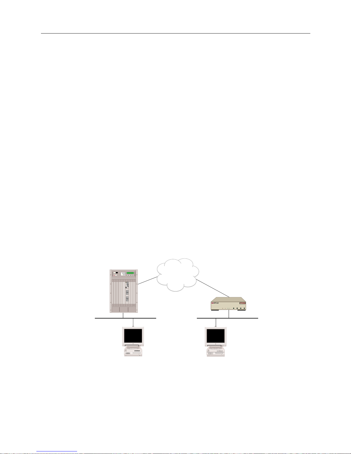
USER’S GUIDE
96 SmartSwitch Remote Access Module
Action:
1. Verify triggered RIP/SAP has successfully started for peers. Iss ue the
dr
console command
and look for the “startin g ” me ssage in the log.
2. Generate a triggered RIP/SAP update req u e st to the devices in questio n. Issue the following
console command for each dev ice:
ipx trigreq <device>
3. Verify that the statistics are incremented properly. Issue the following console commands:
ipx trigrip stats
ipx trigsap stats
4. If routes/services are not propagated on either side, contact Customer Support.
APPLETALK ROUTING
This section provides methods for diagnosing problems in the following areas of AppleTalk
routing:
• AppleTalk routing initialization
• AppleTalk routing over the LAN connection
• AppleTalk routing over the WAN connection
Use the following example configuration to diagnose AppleTalk routing operational problems. The
example below uses AppleTalk addresses, zones, and resource names specific to the example.
Substitute those of your network when you perform the diagnosis steps.
APPLETALK ROUTING INITIALIZATION
Problem:
The SmartS witch Remote Access Module doe s not display the correct AppleTalk Routin g
Initialization messa ges.
ISDN
CSX1200
"Site2"
Net Range: 10-11
Zone: Left Zone
Net Range: 20-21
Zone: Right Zone
Local Mac Remote Mac
MMAC PLUS
Cabletron
Systems
MMAC-Plus with
SmartSWITCH
Remote Access Module
"Site 1"
WORKGROUP REMOTE ACCESS SWITCH
LAN
10BASE-TRXTXSERVICE
CH-2
D-CH
CH-1
SYNC
POWER
LINE
1
CH-2
D-CH
CH-1
SYNC
LINE
2
CH-2
D-CH
CH-1
SYNC
LINE
3
CH-2
D-CH
AGI
CH-1
SYNC
LINE
4
Page 97

9W006 and 9W007 97
P
ROBLEM DIAGNOSIS
AppleTalk Routing
Action:
1. Using SFVRA-CFG, check the system configuration. Make sure that the AppleTalk feature is
enabled for the system. To do this:
a. If it is not already running, start up SFVRA-CFG.
b. From the toolbar, select Functions then select Sites or click the icon.
c. From the displayed list, double click on the site in question.
d. Click on the Systems tab.
e. Select the system in questi on, then click on Edit System Settings.
f. Under AppleTalk information, check to make sure that a check appears next to Enable
(AppleTalk information is included under the Properties tab).
g. If you made a change, downl oad the new configurati on files to e ffected site.
For more detailed instr uctio ns , refer to the follow ing sec tions in the SFVRA Configuration
Manager User’s Guide:
• Fo r enabling AppleTalk: refer to Configu ring the Site ’s Systems in the Configuring Sites
chapter.
• For downloading configur a tion files : refer to Dow n loadin g Co n figura t ion Upda t e s in the
Exporting Configuration Files chapter.
APPLETALK ROUTING OPERATIONAL OVER THE LAN CONNECTION
Problem:
No zones appear in the Mac’s Chooser.
Action:
1. Verify that the AppleTalk LAN port that Local Mac is attached to is in up state by entering the
following console command:
atalk port
If the command shows the port is not in up state, wait for a couple of m inutes and repeat this
step.
2. Check to see if the LAN connection of the port is operational. If the LAN connection is not
operati onal, then correct the problem.
3. If you are using Classic Networking, verify that EtherTalk is used on the Local Mac by opening
the Ne tw ork control panel a s sh own belo w:
Page 98
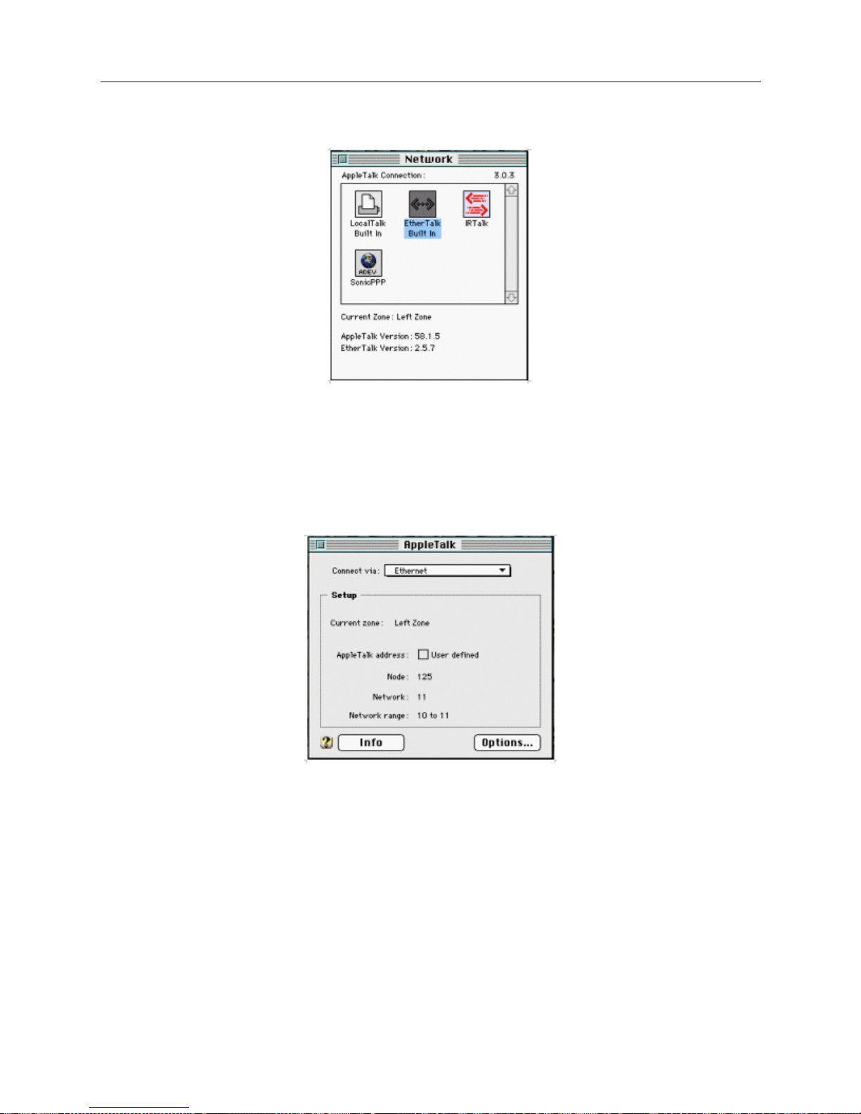
USER’S GUIDE
98 SmartSwitch Remote Access Module
If Ethe rT alk is s el ect ed, a nd n o zones are di sp lay ed, t hen con ta ct y our Di stri butor o r Custome r
Support.
4. If you are using Open Transport, verify that Local Mac has chosen a proper AppleTalk address
within the valid network range (this would be 10-11 for the example network) by opening the
AppleTalk control panel as shown below:
If the Netwo rk Ran ge i s corr ect and the Appl eTalk addr ess is not wi thi n that r an ge, the n tr y to
close the AppleTalk control panel once, and then reopen it. If the AppleTalk address is still
invalid, then try to assign a valid address manuall y by marking User defined box. If you start
seeing zones, then you can take out the User defined tag.
If the Network Range is no t correct, contact your Distributor or Customer Support.
5. If the AppleTalk address of Local Mac is valid, then check which AppleTalk router that Local
Mac is obtaining the information from by selectin g info box in the AppleTalk control panel as
shown below (this can be done if Open Transport is being used):
Page 99
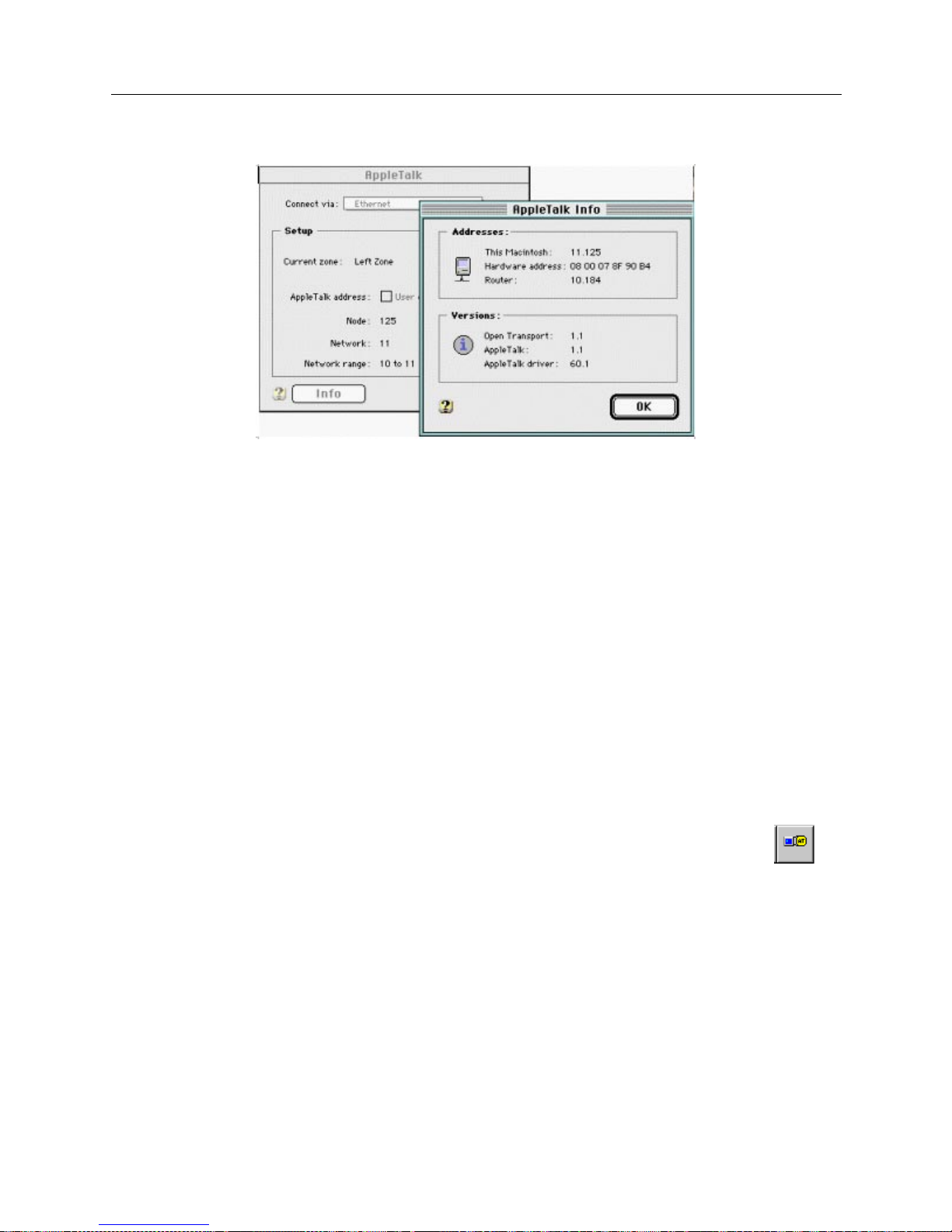
9W006 and 9W007 99
P
ROBLEM DIAGNOSIS
AppleTalk Routing
If the AppleTalk address for the router is not same as the one displayed when issuing
atalk
port
console command, then the Local Mac is getting the information from another router.
Please ref e r to th e documen t fo r th e r out e r.
If the AppleT alk address for Router is the same as the one displayed after iss u ing the
atalk
port
console command, contact your Distributor or Customer Support.
Problem:
Only local zones appear and remote zones are not shown in the Mac’s Chooser:
Action:
1. Verify t hat a static ro ut e t o the remote ne twork is prope rly configured on the Smar tSwitch
Remote Access Module . The stati c route is configu red using SFVRA-CFG.
2. If the static route is not configured correctly, make the appropriate corrections. To check the
AppleTalk static routing information:
a. If it is not already running, start up SFVRA-CFG.
b. From the toolbar, select Functions, click AppleTalk Network, then Systems, or click on
the toolbar.
c. Doub le cl ick on the system in q u e s tion.
d. Click on the Static Routes tab.
e. Double click on the static route in question.
f. Verify the information entered for the static route. Make any necessary changes.
g. If you made any changes, download the new configuration files to the site.
Page 100
USER’S GUIDE
100 SmartSwitch Remote Access Module
For more detailed instr uctio ns , refer to the follow ing sec tions in the SFVRA Configuration
Manager User’s Guide:
• For AppleTalk sta tic rout e info rmation : refer to Configuring AppleTalk Network System Static
Routes in the Config uring App l e Talk Netw ork Inform ation chapter.
• For downloading updated configuration files: refer to Downloading Configuration Updates in
the Exporting Configura tion Files chapter.
3. If the st atic route is prope rly configured, then contact your Distributor or Customer Sup p o rt.
APPLETALK ROUTING OPERATIONAL OVER THE WAN CONNECTION
Problem:
The loca l Ma c is u nabl e t o se e th e re mo te re so urce (Remo te Mac) , wh ich is loc ate d ac ro ss th e W AN.
Action:
1. Ve rif y that App le T a lk Routing is opera t i o n a l on b o th the local and the rem ote LAN.
2. Verify t hat the remote re sources (remote Mac) can be se e n when the WAN connection is up.
3. If the remote resour ce s can be seen wh e n th e connecti on is up but not when the connection is
down, ther e are some problems with making outbound call s. Using SFVRA-CF G, make sure
that the inf o rmation on the remote SmartSwitch Remote Access Module (labele d Site 2 in the
example network) contains a proper AppleTalk address, and that Make calls for AppleTal k data
for the device is enabled.
To check the system’s AppleTalk address and ensure that Make calls for AppleTalk data is
enabled:
a. If it is not already running, start up SFVRA-CFG.
b. From the toolbar, select Functions then select Connection Groups or click the icon.
c. Click on the site’s connecti on group (this should have been configured previou s ly).
d. Click on the site in question, then on the same screen, click on Ed it Group Connections.
e. Double click on the connecti on in question.
f. Click on the Protocols tab.
g. Click on the AppleTalk tab .
h. On this screen, make sure AppleTalk is enabled for the connection, and make sure Make
calls for AppleTalk data is enabled for the site(s) that needs to be able to initiate AppleTalk
calls.
i. On the same screen, make sure that the correct AppleTalk segment has been selected for
this segment. Choices include: none, unnumbered, and the AppleTalk segments you have
configured. The value selected should be either unnumbered or one of the configured
AppleTalk segments. If the value selected is a configured AppleTalk segment, you will
 Loading...