

Cabletron Systems SmartSwitch 9500, 9A600, SmartSwitch 9500 9A600 Hardware And Installation Manual

SmartSwitch 9500
9A600 ATM Module
Hardware and Installation Guide
9032703


Notice
Cabletron Systems reserves the right to make changes in speciÞcations and other information
contained in this document without prior notice. The reader should in all cases consult Cabletron
Systems to determine whether any such changes have been made.
The hardware, Þrmware, or software described in this manual is subject to change without notice.
IN NO EVENT SHALL CABLETRON SYSTEMS BE LIABLE FOR ANY INCIDENTAL, INDIRECT,
SPECIAL, OR CONSEQUENTIAL DAMAGES WHATSOEVER (INCLUDING BUT NOT LIMITED
TO LOST PROFITS) ARISING OUT OF OR RELATED TO THIS MANUAL OR THE INFORMATION
CONTAINED IN IT, EVEN IF CABLETRON SYSTEMS HAS BEEN ADVISED OF, KNOWN, OR
SHOULD HAVE KNOWN, THE POSSIBILITY OF SUCH DAMAGES.
© August 1998 by:
Cabletron Systems, Inc.
35 Industrial Way
Rochester, NH 03867
All Rights Reserved
Printed in the United States of America
Order Number: 9032703
Cabletron Systems and LANVIEW are registered trademarks of Cabletron Systems, Inc.
VT100 is a registered trademark of Digital Equipment Corporation.
Ethernet is a trademark of Xerox Corporation.
i
Notice
FCC Notice
This device complies with Part 15 of the FCC rules. Operation is subject to the following two
conditions: (1) this device may not cause harmful interference, and (2) this device must accept any
interference received, including interference that may cause undesired operation.
NOTE: This equipment has been tested and found to comply with the limits for a Class A digital
device, pursuant to Part 15 of the FCC rules. These limits are designed to provide reasonable
protection against harmful interference when the equipment is operated in a commercial environment.
This equipment uses, generates, and can radiate radio frequency energy and if not installed in
accordance with the operatorÕs manual, may cause harmful interference to radio communications.
Operation of this equipment in a residential area is likely to cause interference in which case the user
will be required to correct the interference at his own expense.
WARNING: Changes or modiÞcations made to this device which are not expressly approved by the
party responsible for compliance could void the userÕs authority to operate the equipment.
VCCI Notice
This is a Class A product based on the standard of the Voluntary Control Council for Interference by
Information Technology Equipment (VCCI). If this equipment is used in a domestic environment,
radio disturbance may arise. When such trouble occurs, the user may be required to take corrective
actions.
Industry Canada Notice
This digital apparatus does not exceed the Class A limits for radio noise emissions from digital
apparatus set out in the Radio Interference Regulations of the Canadian Department of
Communications.
Le prŽsent appareil numŽrique nÕŽmet pas de bruits radioŽlectriques dŽpassant les limites applicables
aux appareils numŽriques de la class A prescrites dans le R•glement sur le brouillage radioŽlectrique
ŽdictŽ par le minist•re des Communications du Canada.
ii

Notice
Declaration of Conformity
Addendum
Application of Council Directive(s):
ManufacturerÕs Name:
ManufacturerÕs Address:
European Representative Name:
European Representative Address:
Conformance to Directive(s)/Product Standards:
Equipment Type/Environment:
We the undersigned, hereby declare, under our sole responsibility, that the equipment packaged with
this notice conforms to the above directives.
89/336/EEC
73/23/EEC
Cabletron Systems, Inc.
35 Industrial Way
PO Box 5005
Rochester, NH 03867
Mr. J. Solari
Cabletron Systems Limited
Nexus House, Newbury Business Park
London Road, Newbury
Berkshire RG13 2PZ, England
EC Directive 89/336/EEC
EC Directive 73/23/EEC
EN 55022
EN 50082-1
EN 60950
Networking Equipment, for use in a
Commercial or Light
Industrial Environment.
Mr. Ronald Fotino Mr. J. Solari
____________________________________________________ ______________________________________________________
Full Name Full Name
Principal Compliance Engineer Managing Director - E.M.E.A.
____________________________________________________ ______________________________________________________
Title Title
Rochester, NH, USA Newbury, Berkshire, England
____________________________________________________ ______________________________________________________
Location Location
iii

Notice
iv

Chapter 1 Introduction
Document Objectives.................................................................................................... 1-1
Overview........................................................................................................................ 1-2
Features........................................................................................................................... 1-4
Processor .................................................................................................................1-4
Cabletron Systems ASICs ..................................................................................... 1-4
System Management ............................................................................................. 1-4
Connectivity............................................................................................................ 1-4
Early Packet Discard (EPD) and Partial Packet Discard (PPD)....................... 1-5
LANVIEW LEDs .................................................................................................... 1-5
Related Manuals............................................................................................................ 1-5
Getting Help .................................................................................................................. 1-6
Contents
Chapter 2 Installing the 9A600 Module
The Reset Switch ...........................................................................................................2-3
The Module Card DIP Switch ..................................................................................... 2-4
Installing an ANIM....................................................................................................... 2-5
Chapter 3 Operation
ATM Cell TrafÞc Flow in the 9A600 ........................................................................... 3-2
Cabletron Systems ASICs ..................................................................................... 3-2
i960HD Processor................................................................................................... 3-2
System Management Buses .........................................................................................3-3
SMB-1 Bus ............................................................................................................... 3-3
SMB-10 Bus ............................................................................................................. 3-3
System Diagnostic Controller...................................................................................... 3-4
DC/DC Converter ........................................................................................................3-4
v

Contents
Chapter 4 LANVIEW LEDs
ANIM LEDs ............................................................................................................4-3
Chapter 5 General Specifications
Operating SpeciÞcations ..............................................................................................5-1
Environmental Requirements ..............................................................................5-1
Regulatory Compliance.........................................................................................5-1
Service............................................................................................................................. 5-1
Physical...........................................................................................................................5-2
Device SpeciÞcations ....................................................................................................5-2
ANIM SpeciÞcations.....................................................................................................5-2
ANIM-21/3 ............................................................................................................. 5-3
ANIM-29/3 ............................................................................................................. 5-4
ANIM-29/3LR ........................................................................................................ 5-5
ANIM-31/2 ............................................................................................................. 5-6
ANIM-39/2 ............................................................................................................. 5-7
ANIM-39/2LR ........................................................................................................ 5-8
ANIM-67/2 ............................................................................................................. 5-9
ANIM-77/2 ........................................................................................................... 5-10
ANIM-22/4 ........................................................................................................... 5-11
vi

Introduction
Document Objectives
This document, the SmartSwitch 9500 9A600ATM Module Hardware and Installation
Guide , contains introductory, installation and speciÞcation information for the
support of the 9A600 SmartSwitch Module. Use this guide to learn about the
following topics:
Chapter 1
NOTE
¥ Overview of the 9A600
¥ Installing the 9A600 in the SmartSwitch 9500 chassis
¥ Installing ATM Network Interface Modules (ANIMs)
¥ Learning the hardware speciÞcations of the 9A600 and the available ANIMs
Prior to installing the 9A600, you should have a working knowledge of ATM
networking principles.
In this document, the Cabletron Systems SmartSwitch 9000 chassis is referred to
as the “SmartSwitch 9500 chassis” which indicates a SmartSwitch 9000 chassis
with one or more 9A600 modules installed.
The 9A600 may also be installed in a SmartSwitch 9000 chassis, which indicates
a chassis without a Cell Transfer Matrix (CTM) backplane.
1-1

Introduction
Overview
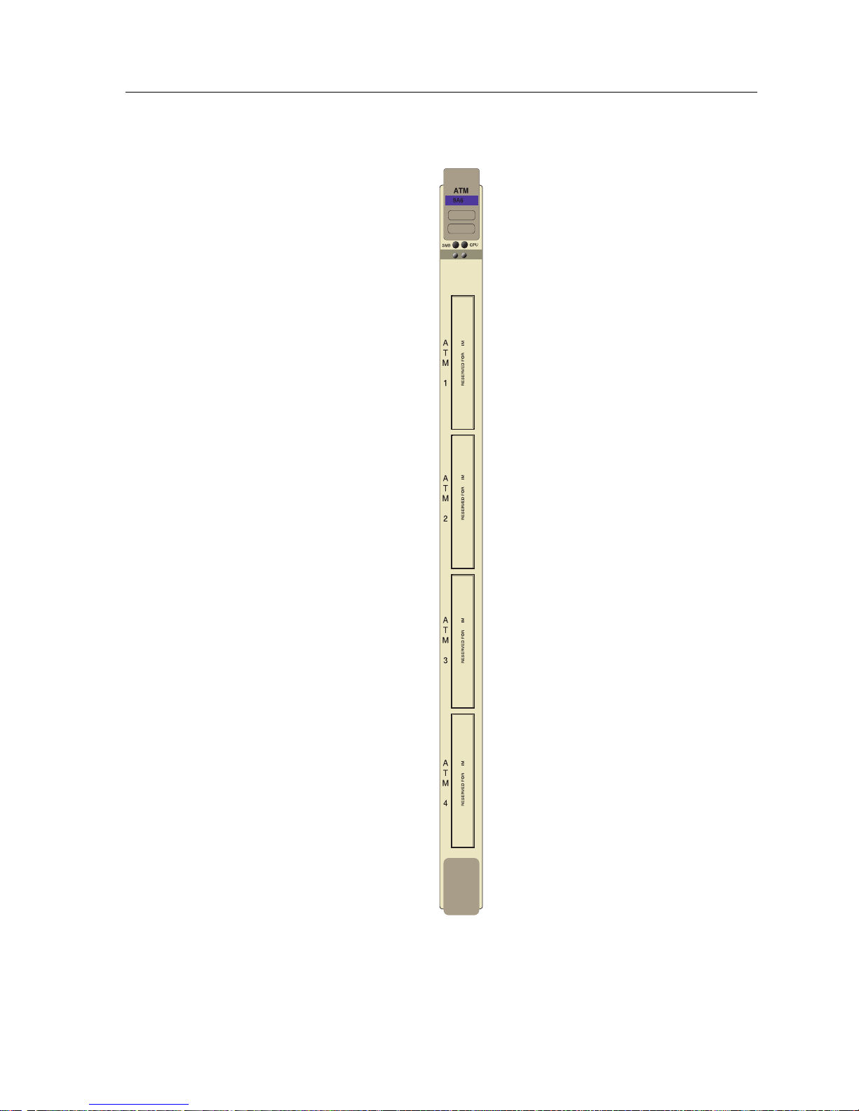
The 9A600 (shown in Figure 1-1) is a 5.4 Gbps, single slot module for the
SmartSwitch 9500 chassis. Up to four ATM Network Interface Modules (ANIMs)
of any type can be plugged into the 9A600 to provide front panel connectivity to
the network. Cabletron Systems ANIMs can support up to 622 Mbps of
bandwidth per port. The 9A600 switches data between the ANIMs that are
installed in the module.
Through its distributed switching architecture, the 9A600 allows all the modules
in the chassis to appear as a single entity, with a single IP address and a single
ATM address. The individual i960 processors are transparent to the network
manager and management applications. A fully loaded SmartSwitch 9500 chassis
appears as a single switch, with one IP address, and one ATM address.
The 9A600 is fully compatible with the following ATM Forum speciÞcations:
¥ Integrated Local Management Interface (ILMI) 4.0 for autoconÞguration.
¥ UNI v3.0 /3.1 and v4.0 for signalling.
¥ ATM Forum P-NNI 1.0 and IISP 3.0/3.1 routing speciÞcations for establishing
connections between ATM switches.
¥ IETF AToM MIB (RFC 1695) and AToM II MIB.
¥ LANE 1.0 for the management LAN Emulation Client.
1-2
Overview
00
AN
AN
AN
AN
Figure 1-1. The 9A600
1-3

Introduction
Features
The features of the 9A600 are described in the sections below:
Processor
The 9A600 is equipped with an advanced Intel i960 microprocessor. This
microprocessor provides signalling, SNMP management, and serves as the
in-band management LAN Emulation Client (LEC).
Cabletron Systems ASICs
The 9A600 contains four different Cabletron Systems designed ASICs that
provide a variety of switching services. For more information on these ASICs
refer to Chapter 3.
System Management
The 9A600 connects to the two System Management Buses (SMB-1 and SMB-10)
for module management. Management features include the following:
¥ Power and environmental status monitoring
¥ PNNI and ILMI conÞguration
¥ SmartSwitch 9500 chassis IP address assignment
¥ Ability to conÞgure the in-band management LAN Emulation Client
¥ SmartSwitch 9500 chassis SNMP community names and trap IP address
assignment
¥ Ability to access Local Management screens of any module installed in the
chassis
Connectivity
The 9A600 can be equipped with a variety of front panel interfaces called ATM
Network Interface Modules (ANIMs). ANIMs provide a variety of physical layer
cabling options, including the following:
¥ Unshielded Twisted Pair (UTP) using OC-3.
¥ Multimode Fiber Optic Cable (MMF) using OC-3 or OC-12.
¥ Single Mode Fiber Optic Cable (SMF) using OC-3 or OC-12.
¥ Coaxial Cable using DS-3.
ANIMs are also capable of handling varying amounts of bandwidth including
SONET OC3/SDH, and STS-3/STM-1 (155 Mbps), SONET OC12/SDH
(622 Mbps) and DS3 (45 Mbps).
1-4

Related Manuals
Early Packet Discard (EPD) and Partial Packet Discard (PPD)
The 9A600 supports early and partial packet discard to help ensure that quality of
service parameters are met for all connections. EPD and PPD, in conjunction with
trafÞc policing, discard ATM cells that the end device would have to retransmit
(due to buffer overload, line loss, line bit errors, faulty cells etc.) thereby limiting
the amount of bad trafÞc present on the ATM network.
LANVIEW LEDs
The 9A600 uses LANVIEW, The Cabletron Systems built-in visual diagnostic and
status monitoring system. With LANVIEW LEDs, you can quickly identify the
device, port, and physical layer status at a glance.
Related Manuals
The manuals listed below should be used to supplement the procedures and
technical data contained in this manual.
9A656-04 and 9A600 ConÞguration Guide
SmartSwitch 9000 Installation Guide
SmartSwitch 9000 Operations Guide
SmartSwitch 9000 9C300-1 Environmental Module UserÕs Guide
SmartSwitch 9000 9C214-1 AC Power Supply UserÕs Guide
SmartSwitch 9000 Local Management UserÕs Guide
SmartSwitch 9000 6 9C106 Setup and Installation Guide
SmartSwitch 9000 6 Module Local Management UserÕs Guide
1-5
 Loading...