

Cabletron Systems SmartSwitch 9000, MMAC-Plus 9T125-08, SmartSwitch 9000 9T125-08 User Manual

SmartSwitch 9000
9T125-08
User’s Guide
9032051-01


Notice
Notice
Cabletron Systems reserves the right to make changes in specifications and other information
contained in this document without prior notice. The reader should in all cases consult Cabletron
Systems to determine whether any such changes have been made.
The hardware, firmware, or software described in this manual is subject to change without notice.
IN NO EVENT SHALL CABLETRON SYSTEMS BE LIABLE FOR ANY INCIDENTAL, INDIRECT,
SPECIAL, OR CONSEQUENTIAL DAMAGES WHATSOEVER (INCLUDING BUT NOT LIMITED
TO LOST PROFITS) ARISING OUT OF OR RELATED TO THIS MANUAL OR THE INFORMATION
CONTAINED IN IT, EVEN IF CABLETRON SYSTEMS HAS BEEN ADVISED OF, KNOWN, OR
SHOULD HAVE KNOWN, THE POSSIBILITY OF SUCH DAMAGES.
© Copyright April 1998 by:
Cabletron Systems, Inc.
35 Industrial Way
Rochester, NH 03867-5005
All Rights Reserved
Printed in the United States of America
Order Number: 9032051-01
LANVIEW
CompuServe
i960 microprocessor
Ethernet
is a registered trademark, and
is a registered trademark of CompuServe, Inc.
is a registered trademark of Intel Corp.
is a trademark of Xerox Corporation.
SmartSwitch
is a trademark of Cabletron Systems, Inc.
i

Notice
FCC Notice
This device complies with Part 15 of the FCC rules. Operation is subject to the following two
conditions: (1) this device may not cause harmful interference, and (2) this device must accept any
interference received, including interference that may cause undesired operation.
NOTE:
device, pursuant to Part 15 of the FCC rules. These limits are designed to provide reasonable
protection against harmful interference when the equipment is operated in a commercial envir onment.
This equipment uses, generates, and can radiate radio frequency energy and if not installed in
accordance with the operator’s manual, may cause harmful interference to radio communications.
Operation of this equipment in a residential area is likely to cause interference in which case the user
will be required to correct the interference at his own expense.
WARNING:
party responsible for compliance could void the user’s authority to operate the equipment.
This equipment has been tested and found to comply with the limits for a Class A digital
Changes or modifications made to this device which are not expressly approved by the
VCCI Notice
This is a Class A product based on the standard of the Voluntary Control Council for Interference by
Information Technology Equipment (VCCI). If this equipment is used in a domestic environment,
radio disturbance may arise. When such trouble occurs, the user may be required to take corrective
actions.
DOC Notice
This digital apparatus does not exceed the Class A limits for radio noise emissions from digital
apparatus set out in the Radio Interference Regulations of the Canadian Department of
Communications.
Le présent appareil numérique n’émet pas de bruits radioélectriques dépassant les limites applicables
aux appareils numériques de la class A prescrites dans le Règlement sur le brouillage radioélectrique
édicté par le ministère des Communications du Canada.
ii

Notice
DECLARATION OF CONFORMITY
ADDENDUM
Application of Council Directive(s):
89/336/EEC
73/23/EEC
Manufacturer’s Name: Cabletron Systems, Inc.
Manufacturer’ s Address: 35 Industrial Way
PO Box 5005
Rochester, NH 03867
European Representative Name: Mr. J. Solari
European Representative Address: Cabletron Systems Limited
Nexus House, Newbury Business Park
London Road, Newbury
Berkshire RG13 2PZ, England
Conformance to Directive(s)/Product Standards:
EC Directive 89/336/EEC
EC Directive 73/23/EEC
EN 55022
EN 50082-1
EN 60950
Equipment Type/Environment:
Networking Equipment, for use in a
Commercial or Light
Industrial Environment.
We the undersigned, hereby declare, under our sole responsibility, that the equipment packaged with
this notice conforms to the above directives.
Manufacturer Legal Representative in Europe
Mr. Ronald Fotino Mr. J. Solari
____________________________________________________ ______________________________________________________
Full Name Full Name
Principal Compliance Engineer Managing Director - E.M.E.A.
____________________________________________________ ______________________________________________________
Title Title
Rochester, NH, USA Newbury, Berkshire, England
____________________________________________________ ______________________________________________________
Location Location
iii

Notice
iv

Contents
Chapter 1 Introduction
Features...........................................................................................................................1-1
Related Manuals............................................................................................................ 1-3
Getting Help ..................................................................................................................1-4
Chapter 2 Installing the SmartSwitch 9000 Module
Unpacking the Module.................................................................................................2-1
Installing a TPIM...........................................................................................................2-1
User Accessible Components ...................................................................................... 2-2
Setting the Module Card DIP Switch......................................................................... 2-4
Ring Speed ..................................................................................................................... 2-5
Installing the Module into the SmartSwitch 9000 Chassis...................................... 2-5
The Reset Switch ........................................................................................................... 2-7
Chapter 3 Operation
Bridging.......................................................................................................................... 3-2
Transparent Bridging.............................................................................................3-2
Source Route Bridging .......................................................................................... 3-3
SR-TB Bridging....................................................................................................... 3-3
Spanning Tree Algorithm......................................................................................3-4
Flexible Network Bus (FNB)........................................................................................ 3-4
System Management Buses ......................................................................................... 3-4
SMB-1 Bus...............................................................................................................3-5
SMB-10 Bus.............................................................................................................3-5
System Diagnostic Controller...................................................................................... 3-5
DC/DC Converter ........................................................................................................ 3-5
FNB Interface................................................................................................................. 3-6
i960 Core.........................................................................................................................3-6
Chapter 4 LANVIEW LEDs
v

Contents
Chapter 5 Specifications
Safety...............................................................................................................................5-1
Service.............................................................................................................................5-1
Physical...........................................................................................................................5-2
Dimensions .............................................................................................................5-2
Weight......................................................................................................................5-2
Electrical .........................................................................................................................5-2
Appendix A TPIM Specifications
TPIM-T1.........................................................................................................................A-1
TPIM-T2 and TPIM-T4 ................................................................................................A-2
TPIM-F2 and TPIM-F3.................................................................................................A-3
vi

Chapter 1
Introduction
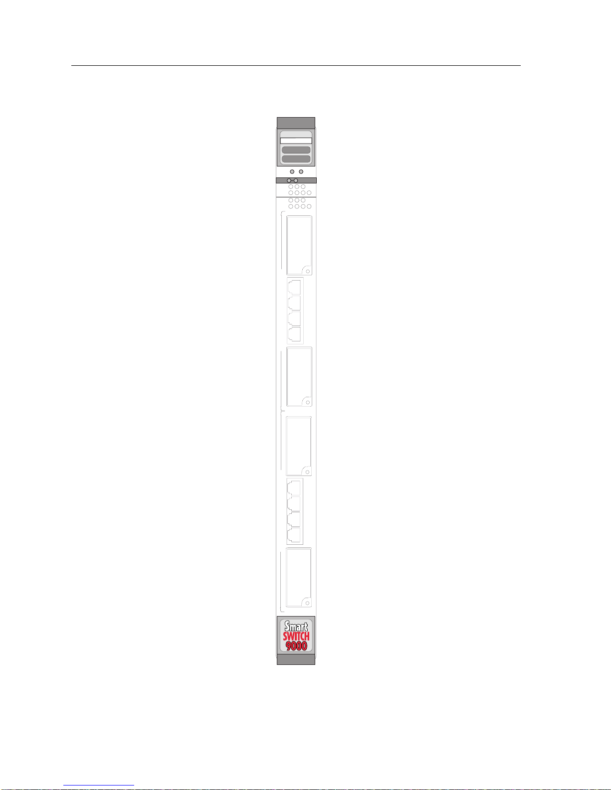
The 9T125-08 MicroLAN™ Switch Extension Module, shown in Figure 1-1, is a three port
Token Ring switch module. This module supports two separate Token Rings with four lobe
connections each, and an interface to the FNB backplane. Each front panel Token Ring also
supports Ring-in/Ring-out connections by using plug-in Token Ring Port Interface modules,
TPIMs.
Features
Processor
The 9T125-08 is equipped with an advanced Intel i960 microprocessor. This microprocessor
provides a platform for all management functions within a scalable RISC-based architecture.
System Management
Interfaces to the two System Management Buses (SMB-1 and SMB-10) for intermodule
management.
Connectivity
The 9T125-08 provides four RJ45 Trunk Coupling Unit (TCU) lobe connector for each of the
two front panel Token Rings. Each front panel T oken Ring has sockets for TPIMs allowing for
Ring-in/Ring-out connections.
SRT Packet Switching
SRT Bridging may occur between the front panel Token Ring connections and
SR-TB bridging to any other module in the chassis via FNB -1 or FNB -2 of the FNB bus. The
module is capable of Transparent Bridging and/or Source Route Bridging. IEEE 802.1d
Spanning Tree Protocol is supported in all bridging functions. Translational bridging
between Source Routing and Transparent Frames types is also performed for packets
destined for the FNB.
1-1
Introduction
TOKEN RING
9T125-08
SMB CPU
FNB
TR1
TR2
T
O
K
E
N
R
I
N
G
1
RING OUT
16 Mb
41
16 Mb
41
1
2
3
4
RING IN
RING OUT
T
1
O
K
E
2
N
R
3
I
N
G
2
4
RING IN
Figure 1-1. The 9T125-08 MicroLAN Switch Extension Module
1-2

Introduction
Management Information Base (MIB) Support
The 9T125-08 provides MIB support including:
• IETF MIB II (RFC 1213)
• IETF Bridge MIBs (RFC 1493 and 1525)
• IEEE 802.5 Token Ring MIB (RFC 1231)
• Cabletron Enterprise MIBs
• RMON
For a complete list of supported MIBs, refer to the release notes provided in the
NOTE
module package.
Ring Security
This feature prevents unauthorized stations from attaching to the ring. Using Local or
Remote Management, the module may be configured as to which MAC addresses are
allowed to operate on the ring.
LANVIEW LEDs
The 9T125-08 uses LANVIEW – the Cabletron Systems built-in visual diagnostic and status
monitoring system. With LANVIEW LEDs, you can quickly identify the device, port, and
physical layer status at a glance.
Hot Swapping
The 9T125-08 can be installed or removed from the chassis while the SmartSwitch 9000 is
powered up without affecting the operation of the remaining modules in the chassis.
Webview
Management of the 9T125-08 may be accomplished using Cabletron’s WEBVIEW. This
allows managing the module though an on-line browser.
Related Manuals
The manuals listed below should be used to supplement the procedures and technical data
contained in this manual.
SmartSwitch 9000 Installation Guide
SmartSwitch 9000 Operations Guide
SmartSwitch 9000 9C300-1 Environmental Module User’s Guide
SmartSwitch 9000 9C214-1 AC Power Supply User’s Guide
SmartSwitch 9000 Local Management User’s Guide
1-3
 Loading...