

Cabletron Systems MMAC-Plus 9H423-26, SmartSwitch 9000, SmartSwitch 9000 9H423-26 User Manual

SmartSwitch 9000
9H423-26
User’s Guide
9032242-02


Notice
Notice
Cabletron Systems reserves the right to make changes in specifications and other information
contained in this document without prior notice. The reader should in all cases consult Cabletron
Systems to determine whether any such changes have been made.
The hardware, firmware, or software described in this manual is subject to change without notice.
IN NO EVENT SHALL CABLETRON SYSTEMS BE LIABLE FOR ANY INCIDENTAL, INDIRECT,
SPECIAL, OR CONSEQUENTIAL DAMAGES WHATSOEVER (INCLUDING BUT NOT LIMITED
TO LOST PROFITS) ARISING OUT OF OR RELATED TO THIS MANUAL OR THE INFORMATION
CONTAINED IN IT, EVEN IF CABLETRON SYSTEMS HAS BEEN ADVISED OF, KNOWN, OR
SHOULD HAVE KNOWN, THE POSSIBILITY OF SUCH DAMAGES.
© Copyright March 1998 by:
Cabletron Systems, Inc.
35 Industrial Way
Rochester, NH 03867-5005
All Rights Reserved
Printed in the United States of America
Order Number: 9032242-02
LANVIEW
CompuServe
i960 microprocessor
Ethernet
is a registered trademark, and
is a registered trademark of CompuServe, Inc.
is a registered trademark of Intel Corp.
is a trademark of Xerox Corporation.
SmartSwitch
is a trademark of Cabletron Systems, Inc.
i

Notice
FCC Notice
This device complies with Part 15 of the FCC rules. Operation is subject to the following two
conditions: (1) this device may not cause harmful interference, and (2) this device must accept any
interference received, including interference that may cause undesired operation.
NOTE:
device, pursuant to Part 15 of the FCC rules. These limits are designed to provide reasonable
protection against harmful interference when the equipment is operated in a commercial envir onment.
This equipment uses, generates, and can radiate radio frequency energy and if not installed in
accordance with the operator’s manual, may cause harmful interference to radio communications.
Operation of this equipment in a residential area is likely to cause interference in which case the user
will be required to correct the interference at his own expense.
WARNING:
party responsible for compliance could void the user’s authority to operate the equipment.
This equipment has been tested and found to comply with the limits for a Class A digital
Changes or modifications made to this device which are not expressly approved by the
VCCI Notice
This is a Class A product based on the standard of the Voluntary Control Council for Interference by
Information Technology Equipment (VCCI). If this equipment is used in a domestic environment,
radio disturbance may arise. When such trouble occurs, the user may be required to take corrective
actions.
DOC Notice
This digital apparatus does not exceed the Class A limits for radio noise emissions from digital
apparatus set out in the Radio Interference Regulations of the Canadian Department of
Communications.
Le présent appareil numérique n’émet pas de bruits radioélectriques dépassant les limites applicables
aux appareils numériques de la class A prescrites dans le Règlement sur le brouillage radioélectrique
édicté par le ministère des Communications du Canada.
ii

Notice
DECLARATION OF CONFORMITY
ADDENDUM
Application of Council Directive(s):
89/336/EEC
73/23/EEC
Manufacturer’s Name: Cabletron Systems, Inc.
Manufacturer’ s Address: 35 Industrial Way
PO Box 5005
Rochester, NH 03867
European Representative Name: Mr. J. Solari
European Representative Address: Cabletron Systems Limited
Nexus House, Newbury Business Park
London Road, Newbury
Berkshire RG13 2PZ, England
Conformance to Directive(s)/Product Standards:
EC Directive 89/336/EEC
EC Directive 73/23/EEC
EN 55022
EN 50082-1
EN 60950
Equipment Type/Environment:
Networking Equipment, for use in a
Commercial or Light
Industrial Environment.
We the undersigned, hereby declare, under our sole responsibility, that the equipment packaged with
this notice conforms to the above directives.
Manufacturer Legal Representative in Europe
Mr. Ronald Fotino Mr. J. Solari
____________________________________________________ ______________________________________________________
Full Name Full Name
Principal Compliance Engineer Managing Director - E.M.E.A.
____________________________________________________ ______________________________________________________
Title Title
Rochester, NH, USA Newbury, Berkshire, England
____________________________________________________ ______________________________________________________
Location Location
iii

Notice
Safety Information
CLASS 1 LASER TRANSCEIVERS
The 9H423-26 is a Class 1 Laser Product
The 9H423-26 uses a Class 1 Laser transceiver . Read the f ollo wing safety
information before installing or operating these adapters.
The Class 1 laser transceivers use an optical feedback loop to maintain Class 1 operation
limits. This control loop eliminates the need for maintenance checks or adjustments. The
output is factory set, and does not allow any user adjustment. Class 1 Laser transceivers
comply with the following safety standards:
• 21 CFR 1040.10 and 1040.11 U.S. Department of Health and
Human Services (FDA).
• IEC Publication 825 (International Electrotechnical Commission).
• CENELEC EN 60825 (European Committee for Electrotechnical
Standardization).
When operating within their performance limitations, laser transceiver output meets the
Class 1 accessible emission limit of all three standards. Class 1 levels of laser radiation are not
considered hazardous.
Laser Radiation and Connectors
When the connector is in place, all laser radiation remains within the fiber. The maximum
amount of radiant power exiting the fiber (under normal conditions) is -12.6 dBm or 55 x 10
watts.
Removing the optical connector from the transceiver allows laser radiation to emit directly
from the optical port. The maximum radiance from the optical port (under worst case
conditions) is 0.8 W cm
Do not use optical instruments to view the laser output. The use of optical instruments to
view laser output increases eye hazard. When viewing the output optical port, power must
be removed from the network adapter.
-2
or 8 x 10
3
W m
2
sr-1.
-6
iv

Chapter 1 Introduction
Features...........................................................................................................................1-2
Related Manuals............................................................................................................ 1-6
Getting Help ..................................................................................................................1-6
Chapter 2 Installing the 9H423-26 Module
Contents
Unpacking the Module.................................................................................................2-1
User-Accessible Components...................................................................................... 2-1
Setting the Module DIP Switch...................................................................................2-2
Installing the Module in the SmartSwitch 9000 Chassis ......................................... 2-4
The Reset Switch ........................................................................................................... 2-6
Chapter 3 Operation
FENIB.............................................................................................................................. 3-2
SmartSwitch ASIC......................................................................................................... 3-3
Traditional Switch..................................................................................................3-3
VLAN.............................................................................................................................. 3-3
VLAN Domains......................................................................................................3-4
Fully Meshed VLAN Domains ............................................................................ 3-5
SecureFast VLAN Switches......................................................................................... 3-5
i960 Core.........................................................................................................................3-6
INB NIB .......................................................................................................................... 3-6
System Management Buses ......................................................................................... 3-6
SMB-1 Bus............................................................................................................... 3-6
SMB-10 Bus............................................................................................................. 3-7
System Diagnostic Controller...................................................................................... 3-7
DC/DC Converter ........................................................................................................ 3-7
INB Interface..................................................................................................................3-7
ITDM Arbitration levels................................................................................... 3-8
Monarch/Slave SmartSwitch 9000 Modules ................................................ 3-9
Chapter 4 LANVIEW LEDs
v

Contents
Chapter 5 Specifications
Technical Specifications................................................................................................5-1
CPU..........................................................................................................................5-1
Memory ...................................................................................................................5-1
Standards.................................................................................................................5-1
Network Interfaces ................................................................................................5-1
Safety...............................................................................................................................5-2
Service.............................................................................................................................5-2
Physical...........................................................................................................................5-2
Dimensions .............................................................................................................5-2
Weight......................................................................................................................5-2
Environment...........................................................................................................5-3
Appendix A 9H423-26 Cabling Requirements
Overview.......................................................................................................................A-1
Fast Ethernet Standard Requirements.......................................................................A-2
100BASE-TX...........................................................................................................A-2
100BASE-FX...........................................................................................................A-7
Why is CAT 5 Cable Necessary for 100BASE-TX? ...........................................A-7
Why are CAT 5 Connectors Necessary for 100BASE-TX?............................. A-11
Fiber Optic Cabling.............................................................................................A-13
vi

Introduction
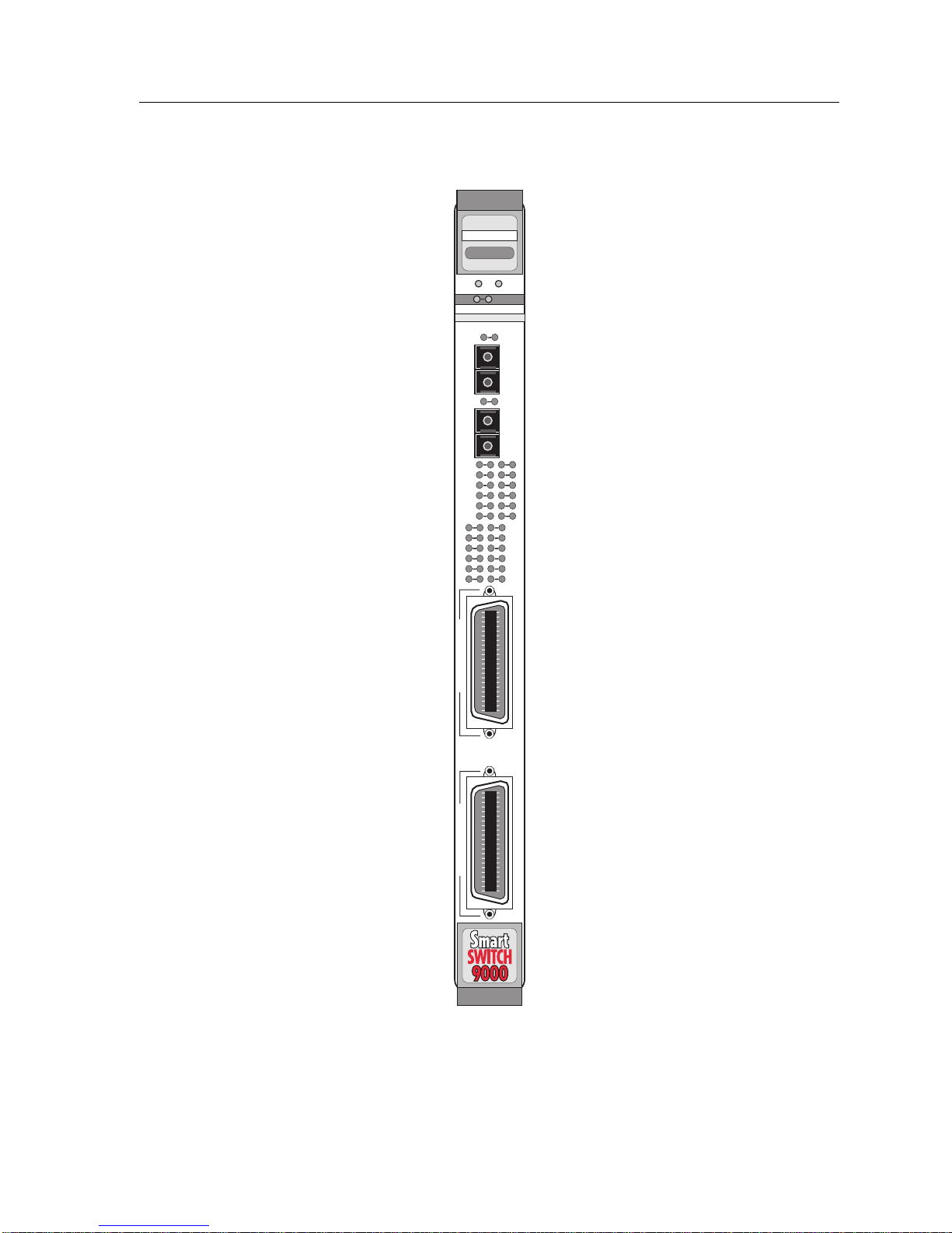
The 9H423-26 (Figure 1-1) is a switching module with twenty-six 100 Mbps
Ethernet ports. The module is configured with two RJ21 connectors (Category 5
rated), providing twenty-four ports, and two multimode fiber SC connectors.
Each module also provides an additional port that connects directly to the
Internal Network Bus (INB) backplane interface. This module uses a SmartSwitch
ASIC design and an advanced Intel i960
provides a platform for all management functions within a scalable RISC-Based
Architecture.
Chapter 1
®
microprocessor. This microprocessor
This module can operate in two modes: either as a 26-port Ethernet traditional
switch (using 802.1d standards) with a high speed backbone connection, or as a
SecureFast switch (SFS) with 26 Ethernet connections. Each port can be
configured to operate in the full duplex mode. This configuration allows each
100BASE-T port to provide a full 200 Mbps. The 100BASE-T ports can operate in
either half or full duplex mode. The fiber ports operate only in full duplex mode
and operate only at 100 Mbps.
The 9H423-26 module is specifically designed for use in the wiring closet. A
typical configuration would have clients connected to the module (via the RJ21
connectors) and servers located in data centers connected via the 100 Mbps fiber
uplink.
Network management information is available through a variety of methods. All
information based on Simple Network Management Protocol (SNMP) is
accessible either via an in-band (Front Panel port), Side Band (SMB-10), or via the
Environmental Module’s COM ports. Serial Line Internet Protocol (SLIP) or
Point-to-Point Protocol (PPP) is supported by the Environmental Module’s COM
ports. For more information on the SMB-10, SLIP or PPP refer to the
9000 Local Management User’s Guide
The 9H423-26 also features front panel LANVIEW™ Diagnostic LEDs to offer ata-glance status information about each front panel port as well as the operation of
the overall module.
.
SmartSwitch
1-1

Introduction
Features
Processor
The 9H423-26 module is equipped with an advanced Intel i960 microprocessor.
This microprocessor provides a platform for all management functions such as
Spanning Tree, RMON, and MIB support, within a scalable RISC-Based
architecture.
Fast Packet Switching
The 9H423-26 module incorporates a hardware-based switch design referr ed to as
the SmartSwitch ASIC, a collection of custom ASICs designed specifically for
high-speed switching. Because all frame translation, address lookups, and
forwarding decisions are performed in hardware, these modules can obtain a
throughput performance of greater than 750K pps.
Management
The 9H423-26 features SNMP for local and remote management. Local
management is provided through the RS232 COM ports on the SmartSwitch 9000
Environmental Module, using a standard VT220
TM
terminal or emulator . Remote
management is possible through Cabletron’s SPECTRUM or any SNMPcompliant management tool. Included as management features are the IETF
Standard Management Information Base (MIBs) RMON (RFC 1271), IETF MIB II
(RFC 1213), IETF Bridge MIB (RFC 1493), and a host of other Cabletron enterprise
MIBs. These modules also offer a wide variety of statistical network management
information to enhance network planning and troubleshooting. The 9H423-26
provides information for each front panel Ethernet port, including packet counts
along with errored frame information such as collisions, CRCs, and Giants, via a
variety of industry standard and private MIBS. Industry standard IEEE 802.1d
bridging, including Spanning Tree Algorithm, is supported.
Connectivity
The 9H423-26 module has one interface to the INB and 26 front port connections.
The INB interface is a fixed connection to INB-B that allows the module to
communicate with other SmartSwitch 9000 modules supporting various LAN
technologies including, Token Ring, FDDI, Ethernet, WAN, Fast Ethernet and
ATM. The module is configured with two RJ21 connectors and two SC fiber
connectors. The two RJ21 connectors provide twenty-four 10/100 Mbps Ethernet
ports. The two multimode SC connectors provide 100BASE-FL connections, with
links up to 2000 meters in length.
1-2

NOTE
Introduction
Auto-negotiation
The auto-negotiation feature (available only with the 100BASE-T RJ21 ports)
allows the module to automatically use the fastest rate supported by the device at
the other end (either 10 Mbps or 100 Mbps at either half or full duplex). To
negotiate duplex, both the 9H423-26 and the attached device must be configured
for auto-negotiation. If only the 9H423-26 is configured for auto-negotiation, the
module will set the connection to half duplex at either the 10 Mbps or 100 Mbps
rate. This technology is similar to how modems negotiate transmission speed,
finding the highest transmission rate possible. Similarly, auto-negotiation
determines the highest common speed between two devices and communicates at
that speed. If no common speed is detected, the device will be partitioned.
RJ21 connections are capable of auto-negotiation, and can operate at 10 Mbps or
100 Mbps, full or half duplex. Fiber connections can only operate at the 100
Mbps rate, full duplex.
NOTE
Standard Ethernet/Full Duplex Operation
The 9H423-26 module supports 100BASE technology. This allows each port on the
module to be configured, through local and or remote management (SNMP), to
operate in standard Fast Ethernet mode (simplex) or full duplex mode. Operating
in standard Fast Ethernet mode limits bandwidth to 100 Mbps per port, while
operating in duplex mode doubles bandwidth from 100 Mbps to 200 Mbps per
port.
Management Information Base (MIB) Support
The 9H423-26 module provides MIB support including:
• RMON (RFC 1757)
• IETF MIB II (RFC 1213)
• IETF Bridge MIB (RFC 1493)
and a host of other Cabletron Enterprise MIBs.
For a complete list of supported MIBs, refer to the release notes provided with the
9H423-26.
1-3

Introduction
INB
The 9H423-26 module attaches to INB-B of the SmartSwitch 9000 Backplane. The
INB backplane is designed to transport fixed-length data blocks between modules
in the SmartSwitch 9000 using an INB Time Division Multiplexing (ITDM) design.
The SmartSwitch 9000 INB bus delivers 2.5 Gbps of true data bandwidth with all
control and management communication being serviced on the 8-bit out-of-band
bus. The time slices of the INB manager operate in all three modes at once,
without user intervention.
Arbitration for the backplane is accomplished in the INB Time Division
Multiplexing (ITDM) logic. The arbitration is a three-level scheme that ensures
that no one can get the backplane for more than one time slice at a time.
The ITDM RAM contains 256 4-bit locations. This RAM is used to hold slot
numbers of modules participating in INB backplane arbitration. The arbitration
engine accesses this RAM once every time slice to get a slot number. That slot
number will be granted access on the next time slice if it is requesting. The
arbitration engine is always one time slice ahead, meaning that the value read
from the RAM is for the next time slice, not the current time slice.
LANVIEW LEDs
The 9H423-26 module uses LANVIEW – the Cabletron Systems built-in visual
diagnostic and status monitoring system. With LANVIEW LEDs, you can quickly
identify, at-a-glance, system status as well as the device, port, and physical layer
status. Two LEDs indicate the transmission and reception of data from the INB
SmartSwitch 9000 backplane connection. Each of the 24 Ethernet front panel ports
features two LEDs per port to indicate the port’s Administrative status (enabled/
disabled), LINK status (Link/Nolink), and Data Activity (receiving and
transmitting data).
1-4
Introduction
FAST ENET
9H423-26
SMB CPU
INB
FAST ENET
26
25
F
a
s
t
E
N
E
T
F
a
s
t
E
N
E
T
23
21 22
19
17
15
13
11 12
9 10
7
5
3
1 2
24
20
18
16
14
8
6
4
Figure 1-1. The 9H423-26 Module
1-5

Introduction
Related Manuals
The Cabletron Systems manuals listed below should be used to supplement the
procedures and technical data contained in this manual.
SmartSwitch 9000 Installation Guide
SmartSwitch 9000 9C300-1 Environmental Module User’s Guide
SmartSwitch 9000 9C214-1 AC Power Supply User’s Guide
SmartSwitch 9000 Local Management User’s Guide
INB Terminator Modules Installation Guide
Getting Help
For additional support related to this device or document, contact the Cabletron Systems Global Call
Center:
Phone (603) 332-9400
Internet mail support@ctron.com
FTP ctron.com (134.141.197.25)
Login
Password
BBS (603) 335-3358
Modem setting 8N1: 8 data bits, No parity, 1 stop bit
For additional information about Cabletron Systems or its products, visit the
World Wide Web site:
For technical support, select
To send comments or suggestions concerning this document, contact the
Cabletron Systems Technical Writing Department via the following
email address:
Make sure to include the document Part Number in the email message.
http://www.cabletron.com/
TechWriting@ctron.com
anonymous
your email address
Service and Support
.
Before calling the Cabletron Systems Global Call Center, have the following information ready:
• Your Cabletron Systems service contract number
• A description of the failure
• A description of any action(s) already taken to resolve the problem (e.g., changing mode switches,
rebooting the unit, etc.)
• The serial and revision numbers of all involved Cabletron Systems products in the network
• A description of your network environment (layout, cable type, etc.)
• Network load and frame size at the time of trouble (if known)
• The device history (i.e., have you returned the device before, is this a recurring problem, etc.)
• Any previous Return Material Authorization (RMA) numbers
1-6

Chapter 2
Installing the 9H423-26 Module
The 9H423-26 module occupies a single slot in the SmartSwitch 9000 chassis.
The INB Terminator Modules must be installed on the rear of the chassis before
NOTE
powering up this module. Refer to the INB Terminator Modules Installation
Guide for information and installation procedure.
Install the modules by following the steps described later in this chapter.
Unpacking the Module
1. Carefully remove the module from the shipping box. (Save the box and
packing materials in the event the module must be reshipped.)
2. Remove the module from the plastic bag. Observe all precautions to prevent
damage from Electrostatic Discharge (ESD).
3. Carefully examine the module, checking for damage. If any damage exists,
DO NOT install the module. Contact Cabletron Systems Global Call Center
immediately.
User-Accessible Components
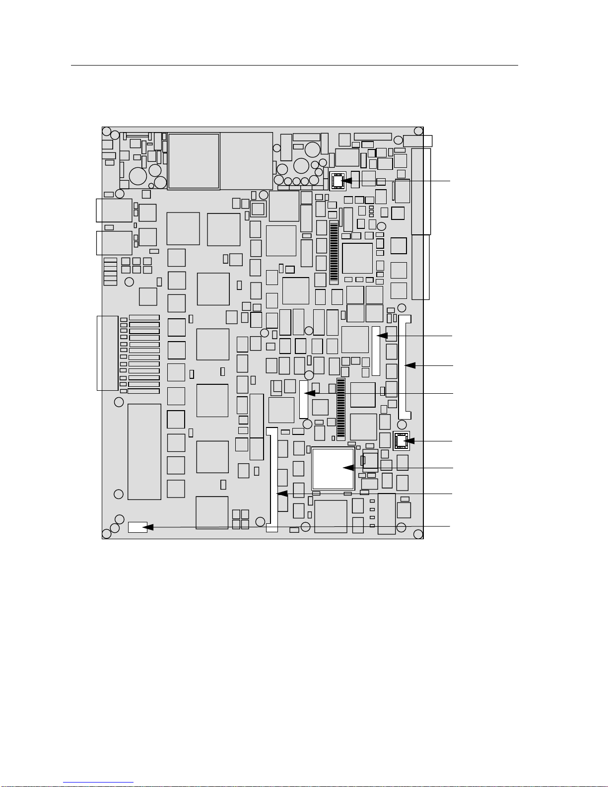
Figure 2-1 shows the various components that can be accessed by users. These
consist of an eight-position dip switch (explained in the next section), replaceable
PROMs, and sockets for memory and flash upgrades. These can be used for future
upgrades. Instructions for installing the components are supplied with the
upgrade kits.
2-1
Installing the 9H423-26 Module
St
SMB1 Prom
Figure 2-1. User-Accessible Components
Setting the Module DIP Switch
CNXSTATS
Connector
Flash
CPM
Boot Prom
i960
DRAM
Dip Switch
The DIP switch on the 9H423-26 module (Figure 2-1 ), is an eight-switch DIP
located near the left, bottom corner of the module. Each switch is set according to
the functions described in Table 2-1. If switch settings are changed, the processor
on the module must be reset, using the reset switch or repowering the module, for
changes to take effect.
2-2
 Loading...