

Page 1

SmartSwitch 9000
9F116-01 User’s Guide
9031184-01
Page 2

Page 3

Notice
Notice
Cabletron Systems reserves the right to make changes in specifications and other information
contained in this document without prior notice. The reader should in all cases consult Cabletron
Systems to determine whether any such changes have been made.
The hardware, firmware, or software described in this manual is subject to change without notice.
IN NO EVENT SHALL CABLETRON SYSTEMS BE LIABLE FOR ANY INCIDENTAL, INDIRECT,
SPECIAL, OR CONSEQUENTIAL DAMAGES WHATSOEVER (INCLUDING BUT NOT LIMITED
TO LOST PROFITS) ARISING OUT OF OR RELATED TO THIS MANUAL OR THE INFORMATION
CONTAINED IN IT, EVEN IF CABLETRON SYSTEMS HAS BEEN ADVISED OF, KNOWN, OR
SHOULD HAVE KNOWN, THE POSSIBILITY OF SUCH DAMAGES.
© Copyright April 1998 by:
Cabletron Systems, Inc.
35 Industrial Way
Rochester, NH 03867-5005
All Rights Reserved
Printed in the United States of America
Order Number:9031184-01
LANVIEW
CompuServe
i960 microprocessor
Ethernet
is a registered trademark, and
is a registered trademark of CompuServe, Inc.
is a registered trademark of Intel Corp.
is a trademark of Xerox Corporation.
SmartSwitch
is a trademark of Cabletron Systems, Inc.
i
Page 4

Notice
FCC Notice
This device complies with Part 15 of the FCC rules. Operation is subject to the following two
conditions: (1) this device may not cause harmful interference, and (2) this device must accept any
interference received, including interference that may cause undesired operation.
NOTE:
device, pursuant to Part 15 of the FCC rules. These limits are designed to provide reasonable
protection against harmful interference when the equipment is operated in a commercial environment.
This equipment uses, generates, and can radiate radio frequency energy and if not installed in
accordance with the operator’s manual, may cause harmful interference to radio communications.
Operation of this equipment in a residential area is likely to cause interference in which case the user
will be required to correct the interference at his own expense.
WARNING:
party responsible for compliance could void the user’s authority to operate the equipment.
This equipment has been tested and found to comply with the limits for a Class A digital
Changes or modifications made to this device which are not expressly approved by the
VCCI Notice
This is a Class A product based on the standard of the Voluntary Control Council for Interference by
Information Technology Equipment (VCCI). If this equipment is used in a domestic environment,
radio disturbance may arise. When such trouble occurs, the user may be required to take corrective
actions.
DOC Notice
This digital apparatus does not exceed the Class A limits for radio noise emissions from digital
apparatus set out in the Radio Interference Regulations of the Canadian Department of
Communications.
Le présent appareil numérique n’émet pas de bruits radioélectriques dépassant les limites applicables
aux appareils numériques de la class A prescrites dans le Règlement sur le brouillage radioélectrique
édicté par le ministère des Communications du Canada.
ii
Page 5

Notice
DECLARATION OF CONFORMITY
ADDENDUM
Application of Council Directive(s):
89/336/EEC
73/23/EEC
Manufacturer’s Name: Cabletron Systems, Inc.
Manufacturer’s Address: 35 Industrial Way
PO Box 5005
Rochester, NH 03867
European Representative Name: Mr. J. Solari
European Representative Address: Cabletron Systems Limited
Nexus House, Newbury Business Park
London Road, Newbury
Berkshire RG13 2PZ, England
Conformance to Directive(s)/Product Standards:
EC Directive 89/336/EEC
EC Directive 73/23/EEC
EN 55022
EN 50082-1
EN 60950
Equipment Type/Environment:
Networking Equipment, for use in a
Commercial or Light
Industrial Environment.
We the undersigned, hereby declare, under our sole responsibility, that the equipment packaged with
this notice conforms to the above directives.
Manufacturer Legal Representative in Europe
Mr. Ronald Fotino Mr. J. Solari
____________________________________________________ ______________________________________________________
Full Name Full Name
Principal Compliance Engineer Managing Director - E.M.E.A.
____________________________________________________ ______________________________________________________
Title Title
Rochester, NH, USA Newbury, Berkshire, England
____________________________________________________ ______________________________________________________
Location Location
iii
Page 6

Notice
iv
Page 7

Contents
Chapter 1 Introduction
Features...........................................................................................................................1-1
Related Manuals............................................................................................................ 1-4
Getting Help ..................................................................................................................1-4
Chapter 2 Installing the MicroLAN Modules
The Reset Switch ........................................................................................................... 2-3
User-Accessible Components...................................................................................... 2-4
Setting the Module Card DIP Switch.........................................................................2-5
Installing an FPIM......................................................................................................... 2-7
Chapter 3 Operation
Flexible Network Bus (FNB)........................................................................................ 3-1
System Management Buses ......................................................................................... 3-2
SMB-1 Bus...............................................................................................................3-2
SMB-10 Bus.............................................................................................................3-2
System Diagnostic Controller...................................................................................... 3-2
DC/DC Converter ........................................................................................................ 3-3
FNB Interface.................................................................................................................3-3
i960 Core.........................................................................................................................3-3
Chapter 4 LANVIEW LEDs
Chapter 5 General Specifications
Safety............................................................................................................................... 5-1
Service.............................................................................................................................5-1
Physical........................................................................................................................... 5-2
Dimensions:............................................................................................................ 5-2
Weight:..................................................................................................................... 5-2
Appendix A FPIM Specifications
FPIM-00 .........................................................................................................................A-1
FPIM-02 and FPIM-04..................................................................................................A-2
FPIM-05 .........................................................................................................................A-3
v
Page 8

Contents
vi
Page 9

Introduction
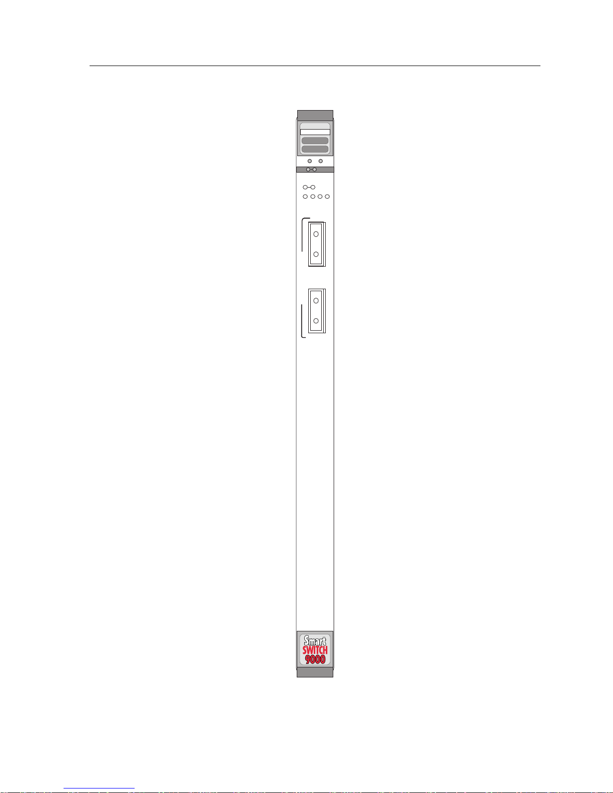
The 9F116-01 MicroLAN™ Module (shown in Figure 1-1) is a two port FDDI
bridge/router used to connect an external FDDI network to one of the two FNB
networks, FNB-1 or FNB-2, on the SmartSwitch 9000 FNB backplane. Another
configuration option allows the module to bridge/route between FNB-1 and
FNB-2 on the FNB backplane. The external FDDI network connects to the 9F11601 using a Dual Attached Station (DAS) interface on the module’s front panel. The
9F116-01 is ANSI X3T9.5-compliant with two instances of Station Management
(SMT), two instances of MAC, and four instances of PHY and PMD (two per
interface).
Chapter 1
Features
Processor
The 9F116-01 is equipped with an advanced Intel i960 microprocessor. This
microprocessor provides a platform for all management functions within a
scalable RISC-based architecture.
System Management
The 9F116-01 interfaces to the two System Management Buses (SMB-1 and
SMB-10) for intermodule management. Management features include the
following:
• Module Insert/Bypass Control
• MAC Placement
• Station Management (SMT) Statistics
• Bridging Statistics (for all interfaces) including
- Frames Filtered
- Frames Forwarded
- All STA Parameters
Hardware Bridging Logic
Hardware frame filter/forward logic increases the bridging performance of the
9F116-01, allowing the module to achieve higher throughputs (up to 50,000
packets per second).
1-1
Page 10

Introduction
Spanning T ree Algorithm
The 9F116-01 supports both IEEE 802.1d and DEC Spanning Tr ee Algorithm (STA)
protocols.
Connectivity
The 9F116-01 provides one FDDI dual attached connector pair from the module
front panel. This connector pair allows the 9F116-01 to act as a DAS (with two
FPIMs installed) or a SAS (with one FPIM) on the SmartSwitch 9000 FNB. The
9F116-01 has three physical FDDI interfaces (front panel, FNB-1, and FNB-2) and
allows bridging between any two of them.
FPIMs
The 9F116-01 uses FDDI Port Interface Modules (FPIMs) to pr ovide several media
options on the front panel interfaces. These FPIMs are available in various media
types including the following:
• Multimode Fiber Optic (FDDI MIC)
• Single Mode Fiber Optic (FDDI MIC)
• Unshielded Twisted Pair (RJ-45)
• Shielded Twisted Pair (RJ-45)
LANVIEW LEDs
The 9F116-01 uses LANVIEW: the Cabletron Systems built-in visual diagnostic
and status monitoring system. With LANVIEW LEDs, you can quickly identify
the device, port, and physical layer status at a glance.
Hot Swapping
The 9F116-01 can be installed or r emoved from the chassis while the SmartSwitch
9000 is powered up without affecting the operation of the rest of the network.
1-2
Page 11
Introduction
FDDI
9F116-01
SMB CPU
FNB
1
1
A
F
D
D
I
1
B
Figure 1-1. The 9F116-01 Module
1-3
Page 12

Introduction
Related Manuals
The manuals listed below should be used to supplement the procedures and
technical data contained in this manual.
SmartSwitch 9000 Installation Guide
SmartSwitch 9000 Operations Guide
SmartSwitch 9000 9C300-1 Environmental Module User’s Guide
SmartSwitch 9000 9C214-1 AC Power Supply User’s Guide
SmartSwitch 9000 Module Local Management User’s Guide
Getting Help
For additional support related to this device or document, contact the Cabletron Systems Global Call
Center:
Login
Password
BBS (603) 335-3358
Modem setting 8N1: 8 data bits, No parity, 1 stop bit
For additional information about Cabletron Systems or its products, visit the
World Wide Web site: http://www.cabletron.com/
For technical support, select Service and Support .
To send comments or suggestions concerning this document, contact the
Cabletron Systems Technical Writing Department via the following
email address:
Make sure to include the document Part Number in the email message.
anonymous
your email address
Before calling the Cabletron Systems Global Call Center, have the following information ready:
• Your Cabletron Systems service contract number
• A description of the failure
• A description of an y action(s) already taken to resolv e the problem (e.g., changing mode switches,
rebooting the unit, etc.)
• The serial and revision numbers of all involved Cabletron Systems products in the network
• A description of your network environment (layout, cable type, etc.)
• Network load and frame size at the time of trouble (if known)
• The device history (i.e., have you returned the device before, is this a recurring problem, etc.)
• Any previous Return Material Authorization (RMA) numbers
1-4
Page 13

Chapter 2
Installing the MicroLAN Modules
SmartSwitch 9000 MicroLAN Modules can be installed in any of the 14 slots that
are available. To install, follow the steps below:
1. Remove the blank panel, covering the slot in which the MicroLAN Module
will be installed. All other slots must remain cover ed to ensure pr oper airflow
and cooling.
2. Unpack the MicroLAN Module by carefully removing it from the shipping
box. (Save the box and packing materials in the event the module must be
reshipped.)
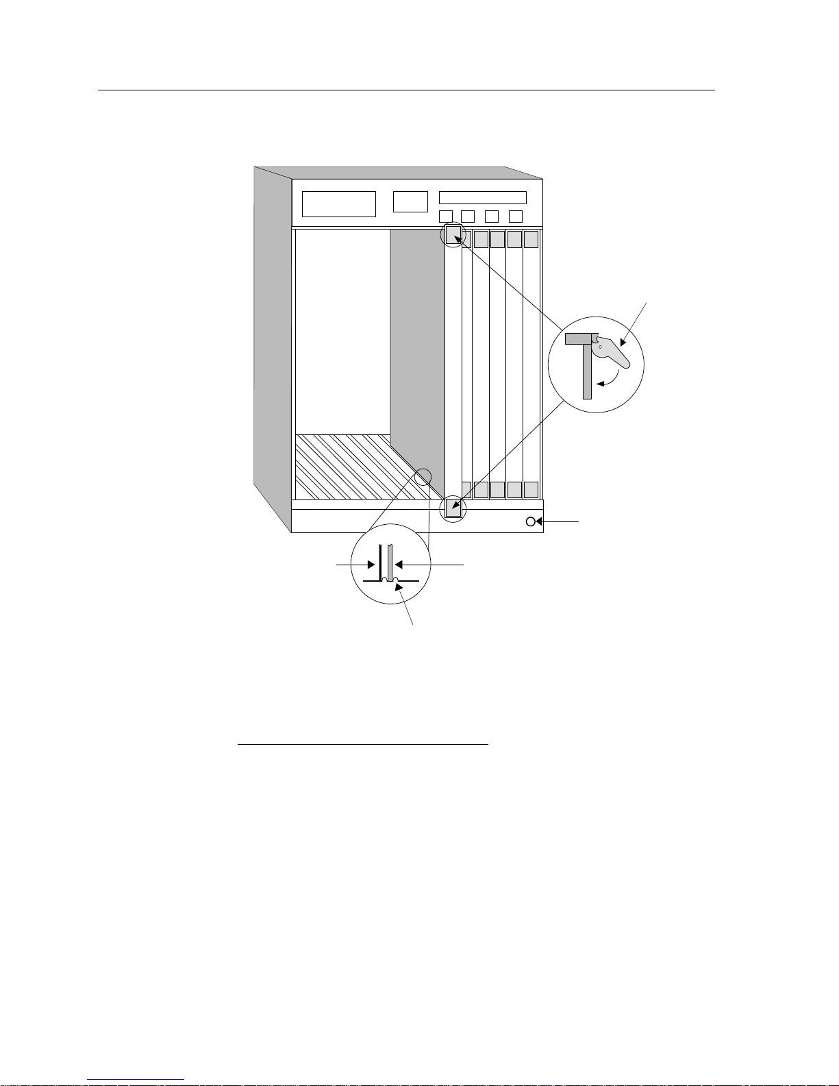
3. Attach one end of the ESD wrist strap packaged with the SmartSwitch 9000
chassis to your wrist. Plug the other end into the ESD Wrist Strap Grounding
receptacle in the lower right corner of the SmartSwitch 9000 Chassis shown in
Figure 2-1.
4. Remove the MicroLAN Module from the plastic bag. (Save the bag in the
event the module must be reshipped.) Observe all precautions to prevent
damage from Electrostatic Discharge (ESD).
5. Examine the MicroLAN Module, carefully checking for damage. If any
damage exists, DO NOT install the module. Immediately contact Cabletron
Systems Technical Support.
6. Install the MicroLAN Module in the chassis by sliding it in any available slot
and locking down the top and bottom plastic tabs, as shown in Figure 2-1.
Take care that each module slides in straight and properly engages the
backplane connectors. When installing a module, ensure that the circuit card
is between the card guides, as shown in Figure 2-1. Check both the upper and
lower tracks.
2-1
Page 14
Installing the MicroLAN Modules
Plastic Tab
Metal Back-Panel
Module
Module Guides
Warning:
Ensure that the circuit card is between the card guides.
Lock down the top and bottom plastic tabs
at the same time, applying even pressure.
Figure 2-1. Installing the MicroLAN Module
Jack for ESD
Wrist Strap
2-2
Page 15
The Reset Switch
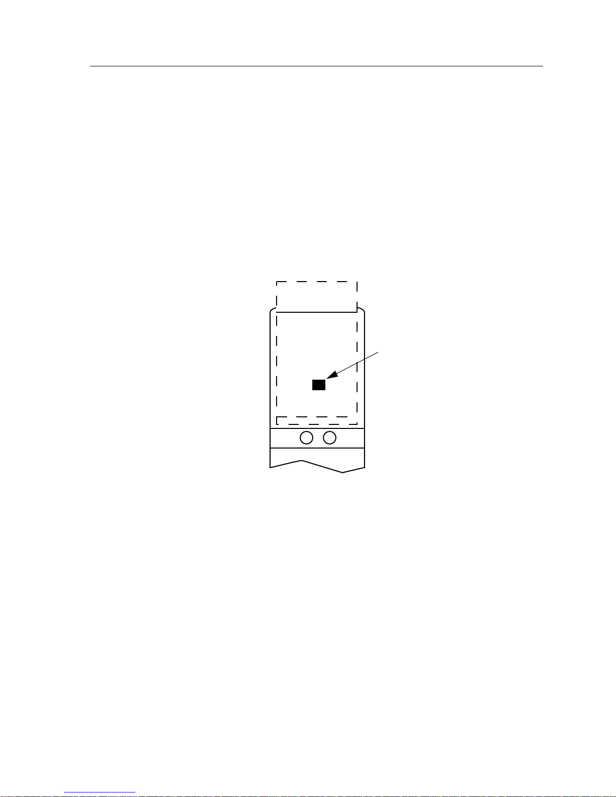
The Reset switch is located on the front panel, under the top plastic tab as shown
in Figure 2-2. It serves two functions:
• Pressing the Reset switch twice within three seconds causes the processor
(i960) to reset.
• Pressing and holding the switch on for three or more seconds causes the
module to shutdown. Pressing and holding again for three seconds restarts the
module.
SNMP management may be used to disable this switch to enhance module
security.
Installing the MicroLAN Modules
SMB
Figure 2-2. The Reset Switch
CPU
Reset Switch
2-3
Page 16
Installing the MicroLAN Modules
User-Accessible Components
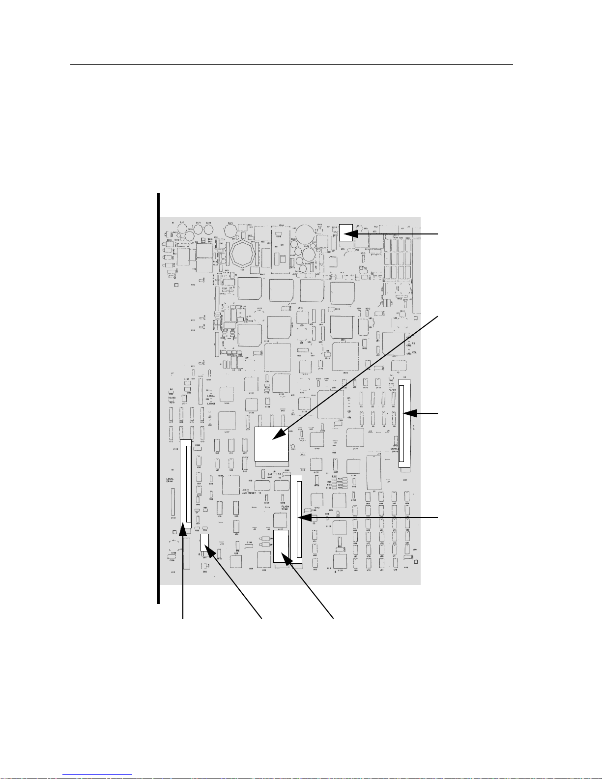
Figure 2-3 shows the various components that are accessible to the user. These
consist of an eight position dip switch (explained in the next section), replaceable
PROMs, and sockets for RAM. These will be used for future upgrades.
Instructions for installing the components will be supplied with the upgrade kit.
SMB-1
PROM
i960
Processor
Shared DRAM
Socket
Flash SIMM
Socket
Socket
2-4
DIP Switch
Figure 2-3. User-Accessible Components
Boot PROMLocal DRAM
Page 17
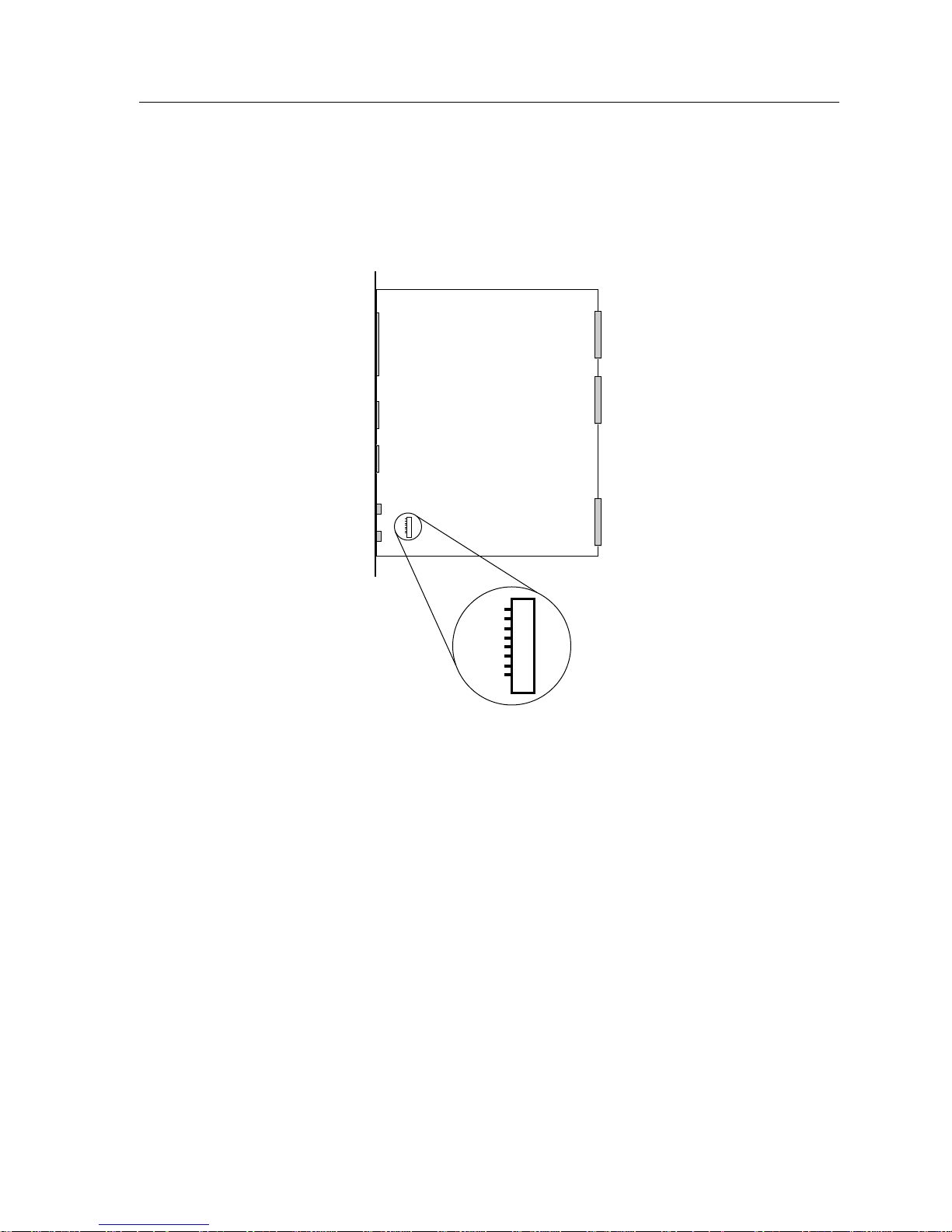
Setting the Module Card DIP Switch
An eight switch DIP switch is located on the module card as shown in Figure 2-3
and Figure 2-4. The functions of the switches are listed in Table 2-1.
Installing the MicroLAN Modules
1
2
3
4
5
6
7
8
Figure 2-4. Location of Module DIP Switch
2-5
Page 18

Installing the MicroLAN Modules
See the Cautions at the end of this table.
Switch Function Description
8
7
Password
NVRAM
Table 2-1. Function of DIP Switch
When toggled, this switch clears user-entered
Clear
passwords stored in NVRAM and restores the
1
default passwords. Once reset you can use the
defaults or enter new passwords.
The module uses NVRAM to store userentered parameters such as IP addresses,
device name, etc. To reset these parameters to
Clear
the factory defaults, toggle this switch. Once
2
reset you can use the defaults or enter new
parameters, which are stored in NVRAM
when the module is powered down, and
remain there until the switch is toggled again.
!
CAUTION
Toggling this switch after pulling the board
out of the SmartSwitch 9000 clears download
6
Force BootP
Download
information from NVRAM and forces image
files to be downloaded from the station
configured to act as that module’s BootP
server.
5 Reserved For Factory Use Only
4 Reserved For Factory Use Only
3 Reserved For Factory Use Only
2 Reserved For Factory Use Only
1 Reserved For Factory Use Only
1. Caution: Do not toggle Switch 8 unless you intend to reset the user-
configured passwords to their factory default settings.
2. Caution: Do not toggle Switch 7 unless you intend to reset the user
parameters to the factory default settings.
2-6
Page 19

Installing an FPIM
The 9F116-01 MicroLAN module is shipped without FPIMs. To install an FPIM,
follow the procedure below:
1. Remove the module if it is installed in the SmartSwitch 9000 chassis.
2. Remove the blank front cover over the FPIM slot.
3. Install the FPIM as shown in Figure 2-5. Ensure that the rear connector is
seated firmly before tightening the two mounting screws.
Installing the MicroLAN Modules
Figure 2-5. Installing an FPIM
2-7
Page 20

Installing the MicroLAN Modules
2-8
Page 21
Operation
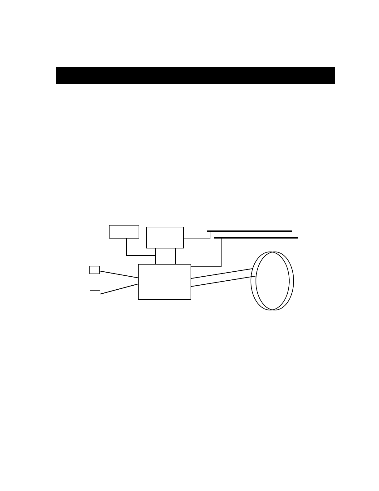
The 9F116-01 provides connectivity between two of the three available interfaces:
the front panel and both FDDI rings on the FNB backplane (FNB-1 and FNB-2).
Bridging/routing can occur between any two interfaces, front panel to either FNB
ring or between the FNB rings (FNB-1 and FNB-2) as shown in Figure 3-1. The
factory default configuration is bridging/routing between the front panel and
FNB-1.
Chapter 3
DC/DC
Converter
A
B
System
Diagnostic
Controller
i960 PLUS Core
Figure 3-1. 9F116-01 Block Diagram
Flexible Network Bus (FNB)
The FNB consists of two dual FDDI networks, FNB-1 and FNB-2, providing up to
400 Mbps of data bandwidth. These FDDI networks are 100% ANSI
FDDI-compliant supporting SMT (version 7.3), MAC, PHY, and PMD standards.
This allows the FNB to traverse multiple SmartSwitch 9000 systems, or connect to
any ANSI FDDI-compliant device, through standard A/B port connections.
SMB-1
SMB-10
FNB-1 and
FNB-2
3-1
Page 22

Operation
System Management Buses
There are two management channels within the SmartSwitch 9000 system: the
SMB-1 and the SMB-10. These buses provide out-of-band management and intermodule management communication.
SMB-1 Bus
The SMB-1 is a 1 Mbps management bus located within the SmartSwitch 9000.
This bus is utilized by all diagnostic controllers in the system including
connectivity modules, power supply modules and the environmental module.
The SMB-1 transports inter-chassis information between system components,
such as power and environmental information, as well as diagnostic messages.
Periodic loop-back tests are performed by all modules that share this bus to
ensure the validity of SMB-1. In the event a failure is detected on SMB-1, the
SMB-10 may be used as an alternate communication channel.
SMB-10 Bus
The SMB-10 is a 10 Mpbs management bus located within the SmartSwitch 9000
which is also used for inter-chassis communication of modules, as well as serving
as an out-of-band management channel into the SmartSwitch 9000. The SMB-10 is
externalized from the chassis via an optional Ethernet Port Interface Module
(EPIM) located on the front of the Environmental Module. Through an EPIM
connection, full SNMP management of the SmartSwitch 9000 is available out-ofband from user data. Modules that share the SMB-10 bus periodically send out
loop-back packets to ensure the validity of SMB-10. In the event a fault is detected
on the SMB-10, the SMB-1 can be used as an alternate communication channel by
the modules.
System Diagnostic Controller
This diagnostic controller is composed of a Z-80 microprocessor and its
supporting logic. The diagnostic controller is designed to control the power-up
sequencing of modules, monitor the 9F116-01 input and output power
parameters, keep watch over the main host processor, as well as monitor the
temperature and control the SMB LANVIEW diagnostic LED. Although the
diagnostic controller and the main host processor can operate independently of
each other if needed, they exchange information about each other’s status and
overall module condition. The information gathered by the diagnostic controller
is available to the network manager via local/remote management and the LCD
located on the environment module. The 9F116-01 has been designed so that in
the event of a diagnostic controller fault, the 9F116-01 will continue to function.
3-2
Page 23

DC/DC Converter
The DC/DC converter converts the 48 VDC on the system power bus to the
necessary operating voltages for its host network services module. The diagnostic
controller controls the operation of the DC/DC converter.
FNB Interface
SmartSwitch 9000 modules are designed with one of two attachment policies. One
allows dual attachment of a module to either FNB-1 or FNB-2; the second allows
dual attachment to both FNB-1 and FNB-2. The 9F116-01 has two dual
attachments to the FNB backplane, connecting to either FNB-1 or FNB-2 or both.
The module can insert into the FNB or bypass it. These flexible configuration
options make the SmartSwitch 9000 ideal for networks designed to Bridge/Route
multiple lower speed LANs to FDDI and/or networks designed using an FDDI
collapsed backbone.
Operation
i960 Core
The i960 core in the FNB module serves two major functions: it provides the
packet forwarding logic and performs all network management services. FNB
modules can be configured to run as layer 2 bridges, layer 3 routers or as
SecureFast Packet Switches. It is possible to run the bridging and routing options
concurrently, but the SFPS option cannot run with bridging and routing.
The i960 core provides the SNMP protocol stacks, as well as support for industry
standard MIBs. Additionally, Cabletron enterprise extension MIBs are supported
for each media type. Advanced management services, such as the Distributed
LAN Monitor , RMON, telnet, and network address to MAC addr ess mapping, are
also provided by the i960 core.
3-3
Page 24

Operation
3-4
Page 25

LANVIEW LEDs
The front panel LANVIEW LEDs indicate the status of the module and may be
used as an aid in troubleshooting. Shown in Figure 4-1 are the LANVIEW LEDs of
the 9F116-01 module.
Chapter 4
FNB Status
(Receive)
FDDI
9F116-01
SMB CPU
FNB
1
1
F
D
D
I
1
System Status
FNB Status
(Transmit)
FDDI Status
A
B
Figure 4-1. 9F116-01 LANVIEW LEDs
4-1
Page 26

LANVIEW LEDs
LED Color State Description
Green Functional Fully operational
Yellow Crippled Not fully operational (i.e., one bad port)
Yellow/Green Booting Blinks yellow and green while booting
Red Reset Normal power-up reset
Red (Flashing) Failed Fatal error has occurred
The functions of the System Management Bus (SMB) and CPU LEDs are listed in
Table 4-1.
Table 4-1. SMB and CPU LEDs
Off Power off Module powered off
The information displayed by the FNB Status LEDs, is dependent on how the
bridging function is configured.
When the front panel port is bridged to one of the FNB rings (FNB-1 or FNB-2),
the LEDs labeled “FNB” indicate the FNB status. The LEDs labeled “1” indicate
the front panel status.
When the two FNB rings (FNB-1 and FNB-2) are bridged together, the LEDs
labeled “FNB” indicate the status of FNB-2. The LEDs labeled “1”, indicate the
status of FNB-1.
The function of the FNB Receive LEDs is listed in Table 4-2.
Table 4-2. FNB Receive LEDs
LED Color State
Yellow (Flashing) Activity
Off No Activity
The function of the FNB Transmit LEDs is listed in Table 4-2.
LED Color State
Green (Flashing) Activity
Off No Activity
4-2
Table 4-3. FNB Transmit LEDs
Page 27
LANVIEW LEDs
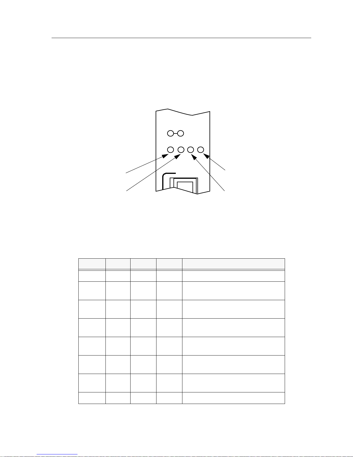
The FDDI status LEDs display the status when bridging to the front panel port
from either FNB ring. The “A” and “B” LEDs indicate the status of the A and B
ports. The “P” and “S” LEDs indicate the status of the primary and secondary
FDDI rings. When bridging between FNB rings, the FDDI status LEDs are not
operational. The FDDI Status LEDs are shown in Figure 4-2.
1
A
P
Figure 4-2. FDDI Status LEDs
B
S
The functions of the FDDI Status LEDs are listed in Table 4-4.
Table 4-4. FDDI Status LEDs
A P S B STATE
Green N/A N/A Green Ports Enabled & Active
Green Green Off Green THRU A, MAC on Primary,
Secondary Bypasses Board
Green Green Yellow Green THRU A, MAC on Primary,
No MAC on Secondary
Green Off Green Green THRU B, MAC on Secondary,
Primary Bypasses Board
Green Yellow Green Green THRU B, MAC on Secondary, No
Green Yellow Off Green THRU, No MAC on Primary,
Green Off Yellow Green THRU, No MAC on Secondary,
Green Green Red Yellow WRAP A, MAC on Primary
MAC on Primary
Secondary Bypasses Board
Primary Bypasses Board
4-3
Page 28

LANVIEW LEDs
A P S B STATE
Green Yellow Red Yellow WRAP A, No MAC on Primary
Yellow Green Red Green WRAP B, MAC on Primary
Yellow Yellow Red Green WRAP B, No MAC on Primary
Green Green Red Green WRAP AB, MAC on Primary
Green Off Off Green BYPASS Primary & Secondary
Green Red Red Green TWISTED A-A, B-B
Yellow Off Off Yellow PCM did not complete, Not Active
Red Off Off Red Ports Disabled
Table 4-4. FDDI Status LEDs (Continued)
4-4
Page 29

General Specifications
The specifications of the 9F116-01 MicroLAN Module are as follows:
Chapter 5
Safety
!
CAUTION
It is the responsibility of the person who sells the system to which the module will
be a part to ensure that the total system meets allowed limits of conducted and
radiated emissions.
This equipment meets the following safety requirements:
• UL 1950
• CSA C22.2 No. 950
• EN 60950
• IEC 950
• EMI Requirements of FCC Part 15 Class A
• EN 55022 Class A
• VCCI Class I
• EMC the following requirements:
EN 50082-1
IEC 801-2 ESD
IEC 801-3 Radiated susceptibility
IEC 801-4 EFT
Service
MTBF (MHBK-217E): >200,000 hrs.
MTTR: <0.5 hr.
5-1
Page 30

General Specifications
Physical
Dimensions:
35.0 D x 44.0 H x 3.0 W centimeters
(13.8 D x 17.4 H x 1.2 W inches)
Weight:
Unit: 1.36 kg. (3 lb)
Shipping: 1.81 kg. (4 lb)
5-2
Page 31

FPIM Specifications
This SmartSwitch 9000 module uses Fiber Port Interface Modules (FPIM) to
provide front panel cable connections. The FPIMs are user-installable. See the
section titled
FPIM-00
The FPIM-00 has a MIC style connector supporting a multimode fiber connection.
The specifications are listed in Table A-1.
Installing an FPIM
Table A-1. FPIM-00 Specifications
on page 2-7.
Appendix A
Parameter Typical Value
Receive
Sensitivity
Peak Input
Power
-30.5 dBm -28.0 dBm — —
-7.6 dBm -8.2 dBm — —
Worst
Case
Worst Case
Budget
Typical
Budget
A-1
Page 32

FPIM Specifications
Transmitter power parameters are listed in Table A-2.
Table A-2. Transmitter Power Parameters
Parameter Typical Value
50/125 µm
fiber
62.5/125 µm
fiber
100/140 µm
fiber
Error Rate Better than 10
The link distance is up to 2 kilometers on the multimode fiber-optic cable as
specified by ANSI MMF-PMD.
-13.0 dBm -15.0 dBm 13.0 dB 17.5 dB
-10.0 dBm -12.0 dBm 16.0 dB 20.5 dB
-7.0 dBm -9.0 dBm 19.0 dB 23.5 dB
FPIM-02 and FPIM-04
The FPIM-02 has an RJ-45 connector supporting an Unshielded Twisted Pair
(UTP) connection. The FPIM-04 has an RJ-45 connector supporting a Shielded
Twisted Pair (STP) connection. The pinouts for both are listed in Table A-3.
-10
Worst
Case
Worst Case
Budget
Typical
Budget
A-2
Table A-3. FPIM-04 Pinouts
Pin Number Represents Pin Number Represents
1 Transmit+ 5 NA
2 Transmit- 6 NA
3 NA 7 Receive+
4 NA 8 Receive-
The link distance is up to 100 meters on unshielded twisted pair cable as specified
by ANSI TP-PMD.
Page 33

FPIM-05
FPIM Specifications
The FPIM-05 has a MIC style connector supporting a Single-mode fiber
connection. The specifications are listed in Table A-4.
Table A-4. FPIM-05 Specifications
Parameter Typical Minimum Maximum
Transmitter Peak Wave
Length
Spectral Width
Rise Time 3.0 nsec 2.7 nsec 5.0 nsec
Fall Time 2.5 nsec 2.2 nsec 5.0 nsec
Duty Cycle 50.1% 49.6% 50.7%
Bit Error Rate Better than 10
The link distance is up to 40 kilometers (max) and 25 kilometers (typical) on
single mode fiber-optic cable as specified by ANSI SMF-PMD.
1300 nm 1270 nm 1330 nm
60 nm - 100 nm
-10
A-3
Page 34

FPIM Specifications
A-4
 Loading...