

Page 1

SmartSwitch 9000
9E423-36
Ethernet Module
User’s Guide
903number
Page 2

Page 3

i
Notice
Notice
Cabletron Systems reserves the right to make changes in specifications and other information
contained in this document without prior notice. The reader should in all cases consult Cabletron
Systems to determine whether any such changes have been made.
The hardware, firmware, or software described in this manual is subject to change without notice.
IN NO EVENT SHALL CABLETRON SYSTEMS BE LIABLE FOR ANY INCIDENTAL, INDIRECT,
SPECIAL, OR CONSEQUENTIAL DAMAGES WHATSOEVER (INCLUDING BUT NOT LIMITED
TO LOST PROFITS) ARISING OUT OF OR RELATED TO THIS MANUAL OR THE INFORMATION
CONTAINED IN IT, EVEN IF CABLETRON SYSTEMS HAS BEEN ADVISED OF, KNOWN, OR
SHOULD HAVE KNOWN, THE POSSIBILITY OF SUCH DAMAGES.
© Copyright February 1998 by:
Cabletron Systems, Inc.
35 Industrial Way
Rochester, NH 03867-5005
All Rights Reserved
Printed in the United States of America
Order Number: 9031945-01
SPECTRUM and LANVIEW are registered trademarks and SmartSwitch is a trademark of Cabletron
Systems, Inc.
Ethernet is a trademark of Xerox Corporation.
Page 4

ii
Notice
FCC Notice
This device complies with Part 15 of the FCC rules. Operation is subject to the following two
conditions: (1) this device may not cause harmful interference, and (2) this device must accept any
interference received, including interference that may cause undesired operation.
NOTE: This equipment has been tested and found to comply with the limits for a Class A digital
device, pursuant to Part 15 of the FCC rules. These limits are designed to provide reasonable
protection against harmful interference when the equipment is operated in a commercial environment.
This equipment uses, generates, and can radiate radio frequency energy and if not installed in
accordance with the operator’s manual, may cause harmful interference to radio communications.
Operation of this equipment in a residential area is likely to cause interference in which case the user
will be required to correct the interference at his own expense.
WARNING: Changes or modifications made to this device which are not expressly approved by the
party responsible for compliance could void the user’s authority to operate the equipment.
VCCI Notice
This equipment is in the 1st Class Category (information equipment to be used in commercial and/or
industrial areas) and conforms to the standards set by the Voluntary Control Council for Interference
by Information Technology Equipment (VCCI) aimed at preventing radio interference in commercial
and/or industrial areas.
Consequently, when used in a residential area or in an adjacent area thereto, radio interference may be
caused to radios and TV receivers, etc.
Read the instructions for correct handling.
Page 5

Notice
DOC Notice
This digital apparatus does not exceed the Class A limits for radio noise emissions from digital
apparatus set out in the Radio Interference Regulations of the Canadian Department of
Communications.
Le présent appareil numérique n’émet pas de bruits radioélectriques dépassant les limites applicables
aux appareils numériques de la class A prescrites dans le Règlement sur le brouillage radioélectrique
édicté par le ministère des Communications du Canada.
iii
Page 6

Notice
iv
Page 7

Chapter 1 Introduction
Features.........................................................................................................................................1-2
Related Manuals ..........................................................................................................................1-5
Getting Help................................................................................................................................. 1-5
Chapter 2 Installing the 9E423-36 Module
Contents
Unpacking the Module ...............................................................................................................2-1
User Accessible Components..................................................................................................... 2-1
Installing the Module in the SmartSwitch 9000 Chassis........................................................ 2-4
The Reset Switch.......................................................................................................................... 2-6
Telco Connector............................................................................................................................2-7
Chapter 3 Operation
ENIB...............................................................................................................................................3-2
SmartSwitch ASIC .......................................................................................................................3-2
i960 Core .......................................................................................................................................3-2
INB NIB.........................................................................................................................................3-3
System Management Buses........................................................................................................3-3
SMB-1 Bus.............................................................................................................................. 3-3
SMB-10 Bus............................................................................................................................ 3-3
System Diagnostic Controller ....................................................................................................3-4
DC/DC Converter....................................................................................................................... 3-4
INB Interface ................................................................................................................................3-4
Chapter 4 LANVIEW LEDs
v
Page 8

Contents
Chapter 5 Specifications
Technical Specifications...............................................................................................................5-1
CPU.........................................................................................................................................5-1
Memory..................................................................................................................................5-1
Standards ...............................................................................................................................5-1
Network Interfaces...............................................................................................................5-1
Safety .............................................................................................................................................5-2
Service............................................................................................................................................5-2
Physical..........................................................................................................................................5-2
Dimensions............................................................................................................................5-2
Weight.....................................................................................................................................5-3
Environment..........................................................................................................................5-3
vi
Page 9

Introduction
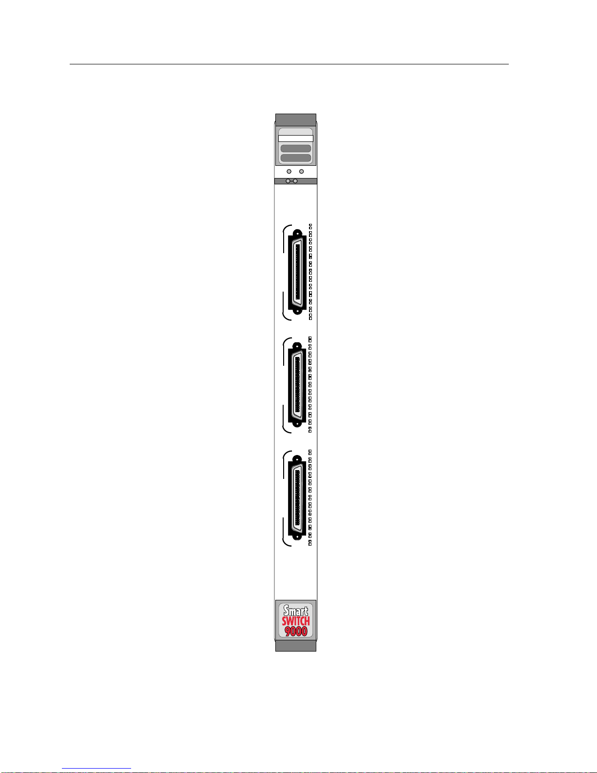
The 9E423-36 (Figure 1-1) is a 36-port switching module. Three RJ-21 Telco
connectors support 36 10BASE-T ports with a port connecting to the Internal
Network Bus (INB) backplane interface. This module uses a SmartSwitch ASIC
design and an advanced Intel i960
a platform for all management functions within a scalable RISC-Based
architecture.
Chapter 1
®
microprocessor. This microprocessor provides
The module can operate in two modes: as a 36-port Ethernet traditional switch
(using 802.1d standards) with a high speed backbone connection or as a Secure
Fast Switch (SFS) with 36 Ethernet connections. Each port of the 9E423-36 can be
configured to operate in the Full Duplex mode. This configuration allows each
port to provide a full 20 Mbps of bandwidth for file servers or high end user
intensive workstations.
Network management information is available through a variety of methods. All
information based on Simple Network Management Protocol (SNMP) is
accessible either via an in-band (Front Panel port), Side Band (SMB-10), or via the
Environmental Module’s COM ports. Serial Line Internet Protocol (SLIP) or
Point-to-Point Protocol (PPP) is supported by the Environmental Module’s COM
ports. For more information on the SMB-10, SLIP or PPP, refer to the SmartSwitch
9000 Local Management User’s Guide.
The 9E423-36 also features front panel LANVIEW™ Diagnostic LEDs to offer at-a-
glance status information about each front panel port, as well as the operation of
the overall module.
Ethernet networks are connected to the 9E423-36 module through three standard
RJ-21 Telco connectors built in the front of the module. Each connector provides
12 Ethernet 10BASE-T connections for UTP and STP links up to 100 meters long.
1-1
Page 10

Introduction
Features
Processor
The 9E423-36 is equipped with an advanced Intel i960 microprocessor. This
microprocessor provides a platform for all management functions such as
Spanning Tree, RMON, and MIB support within a scalable RISC-Based
architecture.
Fast Packet Switching
The 9E423-36 incorporates a hardware-based switch design referred to as the
SmartSwitch ASIC, a collection of custom ASICs designed specifically for high
speed switching. Because all frame translation, address lookups, and forwarding
decisions are performed in hardware, the 9E423-36 can obtain a throughput
performance of greater than 750K pps.
Management
The 9E423-36 features SNMP for local and remote management. Local
management is provided through the RS-232 COM ports on the SmartSwitch 9000
Environmental Module using a standard VT-220 terminal or emulator. Remote
management is possible through Cabletron’s SPECTRUM or any SNMPcompliant management tool. Included as management features are the IETF
Standard Management Information Base (MIBs) RMON (RFC1271), IETF MIB II
(RFC-1213), IETF Bridge MIB (RFC-1493), and a host of other Cabletron enterprise
MIBs. The 9E423-36 also offers the user a wide variety of statistical network
management information to enhance network planning and troubleshooting. This
module provides information for each front panel Ethernet 10BASE-T port,
including packet counts along with errored frame information such as collisions,
CRCs, and Giants, via a variety of industry standard and private MIBS. Industry
standard IEEE 802.1d bridging, including Spanning Tree Algorithm, is supported.
Connectivity
The 9E423-36 module has one interface to the INB and three front panel RJ-21
Telco connectors. The INB interface is a fixed connection to INB-2 that allows the
9E423-36 to communicate with other SmartSwitch 9000 modules supporting
various LAN technologies, including Token Ring, FDDI, Ethernet, WAN and
ATM. Each front panel RJ-21 connector provides 12 Ethernet 10BASE-T
connections for UTP and STP links up to 100 meters in length.
Standard Ethernet/Full Duplex Operation
The 9E423-36 Module supports 10BASE-T. The use of 10BASE-T allows each port
on the 9E423-36 Module to be configured, through local and/or remote
management (SNMP), to operate in standard Ethernet mode (simplex) or full
duplex mode. Operating in standard Ethernet mode limits bandwidth to 10 Mbps
per port, while operating in duplex mode doubles bandwidth from 10 Mbps to 20
Mbps per port.
1-2
Page 11

NOTE
chaptitle
Management Information Base (MIB) Support
The 9E423-36 provides MIB support including:
• RMON (RFC-1757)
• IETF MIB II (RFC-1213)
• IETF Bridge MIB (RFC-1493)
and a host of other Cabletron Enterprise MIBs.
For a complete list of supported MIBs, refer to the release notes provided in the
9E423-36 package.
INB
The 9E423-36 attaches to INB2 of the SmartSwitch 9000 Backplane. The INB has a
capacity of 2.5 Gbps to interconnect SmartSwitch 9000 modules supporting
Ethernet, FDDI, Token Ring, WAN and ATM networks. The INB transports fixed
length data blocks between modules in the SmartSwitch 9000 hub using a Time
Division Multiplexing (TDM) design. Within the INB there is a 64-bit wide data
bus and an eight-bit control management bus. Each module that attaches to the
INB has an INB Network Interface Block (NIB). The INB NIB converts canonical
frames to fixed length data blocks for transmission onto the INB. For data blocks
received from the INB, the INB NIB reassembles the data blocks received from the
INB back into canonical frames for transmission to the SmartSwitch ASIC and
ultimately to the front panel port. The INB can time slice its bandwidth using one
of three methods:
• The default method is standard TDM round-robin bandwidth arbitration.
• The second method is for modules to reserve a specific amount of bandwidth
using MONARCH, Cabletron’s INB Bandwidth Arbitrator.
• The third method permits the lowest slot number to use any bandwidth not
used by the previous two methods.
LANVIEW LEDs
The 9E423-36 uses LANVIEW – the Cabletron Systems built-in visual diagnostic
and status monitoring system. With LANVIEW LEDs, you can quickly identify, at
a glance, system status as well as the device, port, and physical layer status. Two
LEDs indicate the transmission and reception of data from the INB SmartSwitch
9000 backplane connection. Each of the 12 Ethernet front panel ports features two
LEDs per port to indicate the port’s Administrative status (enabled/disabled),
LINK status (Link/Nolink), and Data Activity (receiving and transmitting data).
1--3
Page 12
Introduction
ETHERNET
9E423-36
SMB CPU
INB
36
10
B
A
S
E
T
25
24
10
B
A
S
E
T
13
12
10
B
A
S
E
T
1
1-4
Figure 1-1. The 9E423-36 Module
Page 13

Related Manuals
The manuals listed below should be used to supplement the procedures and
technical data contained in this manual.
SmartSwitch 9000 Installation Guide
SmartSwitch 9000 9C300-1 Environmental Module User’s Guide
SmartSwitch 9000 9C214-1 AC Power Supply User’s Guide
SmartSwitch 9000 Local Management User’s Guide
INB Terminator Modules Installation Guide
Getting Help
If you need additional support related to this device, or if you have any questions,
comments, or suggestions concerning this manual, contact the Cabletron Systems
Global Call Center:
Introduction
Login
Password
BBS (603) 335-3358
Modem setting 8N1: 8 data bits, No parity, 1 stop bit
For additional information about Cabletron Systems or our products,
visit our World Wide Web site:
For technical support, select
Before calling the Cabletron Systems Global Call Center, have the following
information ready:
• Your Cabletron Systems service contract number
• A description of the failure
• A description of any action(s) already taken to resolve the problem (e.g.,
changing mode switches, rebooting the unit, etc.)
• The serial and revision numbers of all involved Cabletron Systems products in
the network
• A description of your network environment (layout, cable type, etc.)
• Network load and frame size at the time of trouble (if known)
• The device history (i.e., have you returned the device before, is this a recurring
problem, etc.)
• Any previous Return Material Authorization (RMA) numbers
anonymous
your email address
http://www.cabletron.com/
Service and Support .
1-5
Page 14

Introduction
1-6
Page 15

Chapter 2
Installing the 9E423-36 Module
The 9E423-36 module occupies a single slot in the SmartSwitch 9000 chassis.
The INB Terminator Modules are purchased separately and must be installed on the rear
NOTE
of the chassis before powering up this module. Refer to the INB Terminator Modules
Installation Guide for information and installation procedure.
Unpacking the Module
1. Carefully remove the module from the shipping box. (Save the box and
packing materials in the event the module must be reshipped.)
2. Remove the module from the plastic bag. Observe all precautions to prevent
damage from Electrostatic Discharge (ESD).
3. Carefully examine the module, checking for damage. If any damage exists,
DO NOT install the module. Contact Cabletron Systems Technical Support
immediately.
User Accessible Components
Figure 2-1 shows the various components that can be accessed by users. These
consist of an eight-position dip switch (explained on the next page), replaceable
PROMs, and sockets for memory and flash upgrades. These will be used for
future upgrades. Instructions for installing the components will be supplied with
the upgrade kit.
2-1
Page 16

Installing the 9E423-36 Module
SMB1 Prom
Boot Prom
Dip
Switch
1
2
3
4
5
6
7
8
Flash
Simm
DRAM
Simm
Stats Engine
Socket
Figure 2-1. User Accessible Components
The DIP switch on the 9E423-36 Module (shown in Figure 2-1), is an eight switch
DIP located near the bottom left corner of the module. Each switch is set
according to the functions described in Table 2-1. If switch settings are changed,
the processor on the module must be reset, using the reset switch or by
repowering the module, for the changes to take effect.
2-2
Page 17

Installing the 9E423-36 Module
Table 2-1. Function of DIP Switch
Switch Function Description
This module stores user entered passwords in
NVRAM (Nonvolatile random access memory). To
clear these passwords, toggle this switch and then
8
Clear
Password
reset the module’s processor. Once the module resets,
-1
factory default passwords are placed in NVRAM. You
can use these default passwords or, if desired, enter
new passwords. To enter new passwords, refer to the
Module Local Management User’s Guide.
This module stores user entered parameters such as IP
addresses, subnet masks, default gateway, default
interface, SNMP traps, bridge configurations and
module specific configurations in NVRAM. To clear
7
Clear
NVRAM
these parameters toggle this switch and then reset the
-2
module’s processor. Once the module resets, factory
default parameters are placed in NVRAM. You can
use the default parameters or, if desired, enter new
parameters. To enter new parameters, refer to the
Module Local Management User’s Guide.
!
CAUTION
This module uses BOOTP (Boot Strap Protocol) to
Force
6
BOOTP
Download
download new versions of the image file into Flash
Memory. This procedure forces image files to be
downloaded from the PC or Workstation, configured
to act as the BOOTP server, connected to the EPIM
port in the Environmental Module.
5 Reserved
4 Reserved
3 Reserved
2 Reserved
1 Reserved
For Factory Use Only
For Factory Use Only
For Factory Use Only
For Factory Use Only
For Factory Use Only
Caution: Do not toggle Switch 8 unless you intend to reset the user configured
passwords to the factory default settings.
Caution: Do not toggle Switch 7 unless you intend to reset the user entered
parameters to the factory default settings.
2-3
Page 18

Installing the 9E423-36 Module
Installing the Module in the SmartSwitch 9000
Chassis
To install the 9E423-36 Module in the SmartSwitch 9000 chassis, follow the steps
below:
1. Remove the blank panel, covering the slot in which the module will be
mounted. All other slots must be covered to ensure proper airflow and
cooling.
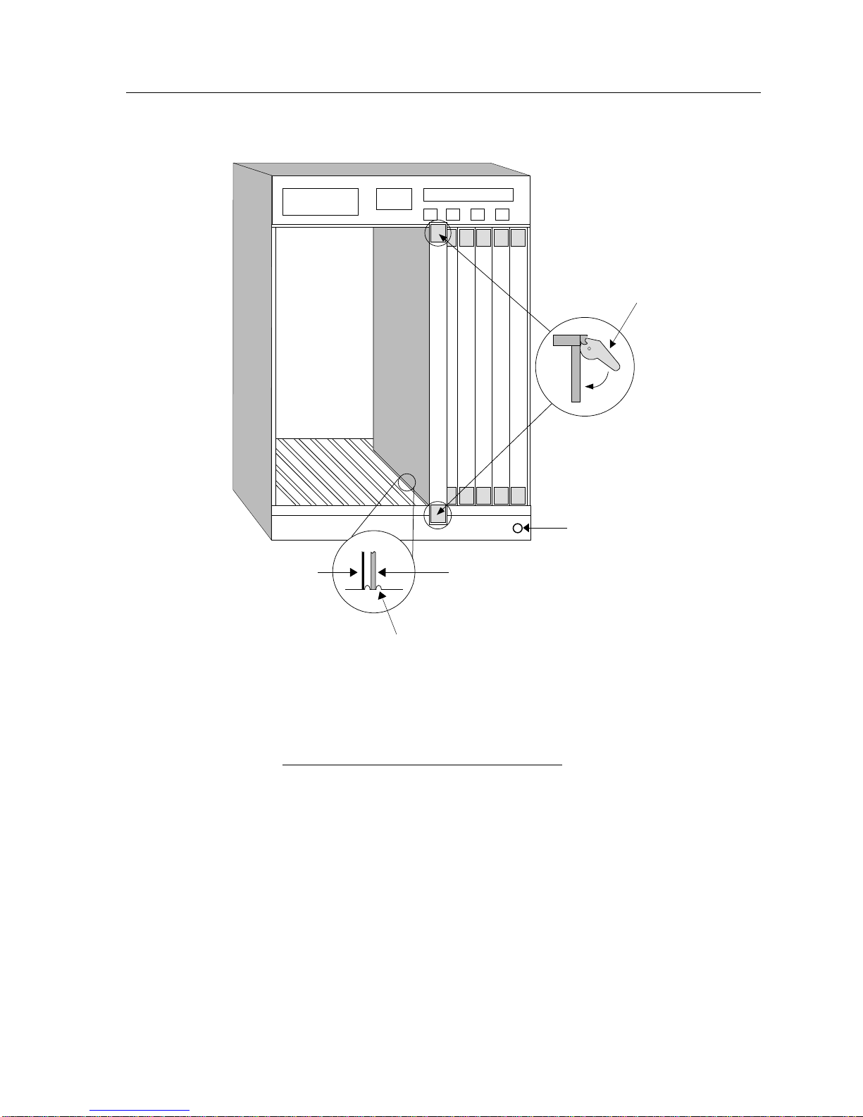
2. Attach one end of the ESD wrist strap packaged with the SmartSwitch 9000
chassis to your wrist. Plug the other end into the jack for the ESD Wrist Strap
in the lower right corner of the SmartSwitch 9000 chassis shown in Figure 2-2.
3. Install the module in the chassis by sliding it into slots and locking down both
the top and bottom plastic tabs, as shown in Figure 2-2. Take care that the
module is between the card guides as shown, it slides in straight, and engages
the backplane connectors properly.
2-4
Page 19
Installing the 9E423-36 Module
Plastic Tab
Metal Back-Panel
Warning:
Ensure that the circuit card is between the card guides.
Lock down the top and bottom plastic tabs
at the same time, applying even pr
Jack for ESD
Wrist Strap
Module
Module Guides
essure.
Figure 2-2. Installing the 9E423-36 Module
2-5
Page 20
Installing the 9E423-36 Module
SMB
CPU
INB
The Reset Switch
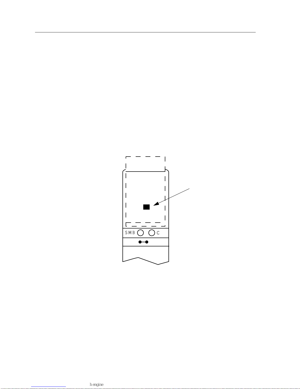
The Reset switch is located on the front panel, under the top plastic tab, as shown
in Figure 2-3. It serves three functions: resetting the i960 processor, shutting down
the module, or restarting the module.
• To reset the i960 processor, press the reset switch twice within three seconds.
• To shut down the module, press and hold the reset switch down for three or
more seconds.
• To restart the module after it has been shut down, press and release the Reset
Switch.
For security, SNMP management can be used to disable the functions of this
switch.
Figure 2-3. The Reset Switch
Reset Switch
2-6
Page 21

Telco Connector
The 9E423-36 front panel has three RJ-21 Telco connectors, each supporting twelve
10BASE-T ports. Table 2-2 details the pinout connections for an RJ-21 Telco
connector.
Pin Signal Wire Color Pin Signal Wire Color
1 RX 1- Blue/White 26 RX 1+ White/Blue
2 TX 1- Orange/White 27 TX 1+ White/Orange
3 RX 2- Green/White 28 RX 2+ White/Green
4 TX 2- Brown/White 29 TX 2+ White/Brown
Installing the 9E423-36 Module
Table 2-2. Pinout Connections RJ-21 Telco Connector
5 RX 3- Gray/White 30 RX 3+ White/Gray
6 TX 3- Blue/Red 31 TX 3+ Red/Blue
7 RX 4- Orange/Red 32 RX 4+ Red/Orange
8 TX 4- Green/Red 33 TX 4+ Red/Green
9 RX 5- Brown/Red 34 RX 5+ Red/Brown
10 TX 5- Gray/Red 35 TX 5+ Red/Gray
11 RX 6- Blue/Black 36 RX 6+ Black/Blue
12 TX 6- Orange/Black 37 TX 6+ Black/Orange
13 RX 7- Green/Black 38 RX 7+ Black/Green
14 TX 7- Brown/Black 39 TX 7+ Black/Brown
15 RX 8- Gray/Black 40 RX 8+ Black/Gray
16 TX 8- Blue Yellow 41 TX 8- Yellow/Blue
17 RX 9- Orange/Yellow 42 RX 9+ Yellow/Orange
18 TX 9- Green/Yellow 43 TX 9+ Yellow/Green
19 RX 10- Brown/Yellow 44 RX 10+ Yellow/Brown
20 TX 10- Gray/Yellow 45 TX 10+ Yellow/Gray
21 RX 11- Blue Violet 46 RX 11+ Violet/Blue
22 TX 11- Orange/Violet 47 TX 11+ Violet/Orange
23 RX 12- Green/Violet 48 RX 12+ Violet/Green
24 TX 12- Brown/Violet 49 TX 12+ Brown
25 N/C Gray/Violet 50 N/C Violet/Gray
2-7
Page 22

Installing the 9E423-36 Module
2-8
Page 23

Operation
The 9E423-36 module is a 37-port device. Three front panel RJ-21 Telco connectors
support 36 10BASE-T ports, each port being a separate collision domain with the
37th port connecting to INB-2.
As shown in Table 3-1, Ethernet Network Interface Blocks (ENIBs) convert data
packets received from any of the 10BASE-T ports into a canonical frame format
before forwarding to the SmartSwitch ASIC, while the Internal Network Bus
Network Interface Block (INB NIB) converts data packets received from the INB
into a canonical format before forwarding to the SmartSwitch ASIC.
Chapter 3
36
Ethernet
Ports
i960
Processor
Smart
Switch
ASIC
Figure 3-1. Packet Flow
Diagnostic
Controller
DC/DC
Convertor
INB
NIB
I
N
B
3-1
Page 24

Operation
ENIB
All data packets destined for a front panel port, the INB, or the i960 are converted
into the canonical format before forwarding to the SmartSwitch ASIC. Network
Interface Blocks (NIBS) check for valid data packets entering the system. If an
errored data packet is found, the SmartSwitch ASIC flags the error and does not
forward the errored data packet to any outbound ports. Once in this common
format, the SmartSwitch ASIC decides (from header information) the port
destination of data packets. Data packets are then converted from the canonical
format to the proper format for the interface destination, whether it is a front
panel port or connection to the INB.
The Ethernet Network Interface Block (ENIB) converts Ethernet data packets
received through front panel ports into a common canonical format that allows
the SmartSwitch ASIC Engine to determine the proper destination port. The ENIB
also converts data packets from the common canonical format back to Ethernet
data packets for transmission out front panel ports.
SmartSwitch ASIC
The SmartSwitch ASIC is a hardware-based switch design that is the key building
block of the SmartSwitch 9000 hub. The SmartSwitch ASIC makes all filtering/
forwarding decisions in custom hardware, as opposed to software like in
traditional bridges. This custom hardware enables the SmartSwitch ASIC to
process over 750K frames per second. The SmartSwitch ASIC is designed to
support up to 64 ports, shared between the host processor, the INB backplane,
and LAN/WAN interfaces on the front panel of SmartSwitch 9000 modules. The
SmartSwitch ASIC can operate in two modes:
• Traditional Switch - When operating as a traditional switch, the SmartSwitch
ASIC makes filtering/ forwarding decisions based on Destination Address
(DA), with standard IEEE 802.1d learning.
• SecureFast Switch (SFS) - When operating as a SecureFast Switch switch, all
filtering/forwarding decisions are made based on a Destination AddressSource Address (DA-SA) pair and the associated receive/transmit port to
deliver virtual circuit capabilities using traditional packet technologies
i960 Core
The i960 core provides the SNMP protocol stacks to support industry standard
MIBs. Additionally, Cabletron enterprise extension MIBs are supported for each
media type. Advanced management services, such as the Distributed LAN
Monitor, telnet and network address to MAC address mapping, are also provided
by the i960 core.
3-2
Page 25

The Host engine sends and receives packets via the CPU’s SmartSwitch ASIC
Interface. This allows the bridge to perform spanning tree protocol and other
bridging functions. The SMB Interfaces provide communication to the Host
Engine for management functions.
INB NIB
Each module that attaches to the Internal Network Bus (INB) has an INB Network
Interface Block (NIB). The INB NIB converts canonical frames to fixed length data
blocks for transmission onto the INB. For data blocks received from the INB, the
INB NIB reassembles the data blocks back into canonical frames for transmission
to the SmartSwitch ASIC.
Operation
System Management Buses
There are two management channels within the SmartSwitch 9000 system: the
SMB-1 and the SMB-10. These buses provide side-band management and intermodule management communication.
SMB-1 Bus
The SMB-1 is a 1Mbs management bus located within the SmartSwitch 9000. This
bus is utilized by all diagnostic controllers in the system including connectivity
modules, power supply modules and the environmental module. The SMB-1
transports inter-chassis information between system components, such as power
and environmental information, as well as diagnostic messages. Periodic
loop-back tests are performed by all modules that share this bus to ensure the
validity of SMB-1. In the event a failure is detected on SMB-1, the SMB-10 may be
used as an alternate communication channel.
SMB-10 Bus
The SMB-10 is a 10Mbs management bus located within the SmartSwitch 9000.
This bus is used for inter-chassis communication of modules as well as serving as
an side-band management channel into the SmartSwitch 9000.
The SMB-10 is externalized from the chassis via an optional Ethernet Port
Interface Module (EPIM) located on the front of the Environmental Module.
Through an EPIM connection, full SNMP management of the SmartSwitch 9000 is
available side-band from user data. Modules that share the SMB-10 bus
periodically send out loop-back packets to ensure the validity of SMB-10. If a fault
is detected on the SMB-10, the SMB-1 can be used as an alternate communication
channel by the modules.
3-3
Page 26

Operation
System Diagnostic Controller
This diagnostic controller is composed of a Z-80 microprocessor and its
supporting logic. The diagnostic controller is designed to control the power-up
sequencing of modules, monitor the 9E423-36 input and output power
parameters, keep watch over the main host processor, monitor the temperature,
and control the SMB LANVIEW diagnostic LEDs. Although the system diagnostic
controller and the main host processor can operate independently of each other if
needed, they exchange information about each others status and overall module
condition. The information gathered by the diagnostic controller is available to
the network manager via local/remote management and the LCD located on the
environment module. The 9E423-36 is designed to continue functioning in the
event of a diagnostic controller fault.
DC/DC Converter
The DC/DC converter converts the 48 VDC on the system power bus to the
necessary operating voltages for its host network services module. The diagnostic
controller monitors and controls the operation of the DC/DC converter.
INB Interface
The INB Backplane is designed to transport fixed length data blocks between
modules in the SmartSwitch 9000 using a Time Division Multiplexing (TDM)
design. The SmartSwitch 9000 INB bus delivers 2.5 Gbps of true data bandwidth
with all control and management communication being serviced on the 8-bit outof-band bus. The INB can time slice its bandwidth using one of three methods:
• The default method is standard TDM round-robin bandwidth arbitration.
• The second method is for modules to reserve a specific amount of bandwidth
using MONARCH, Cabletron’s INB Bandwidth Arbitrator.
• The third method permits the lowest slot number to use any bandwidth not
used by the previous two methods.
3-4
Page 27
LANVIEW LEDs
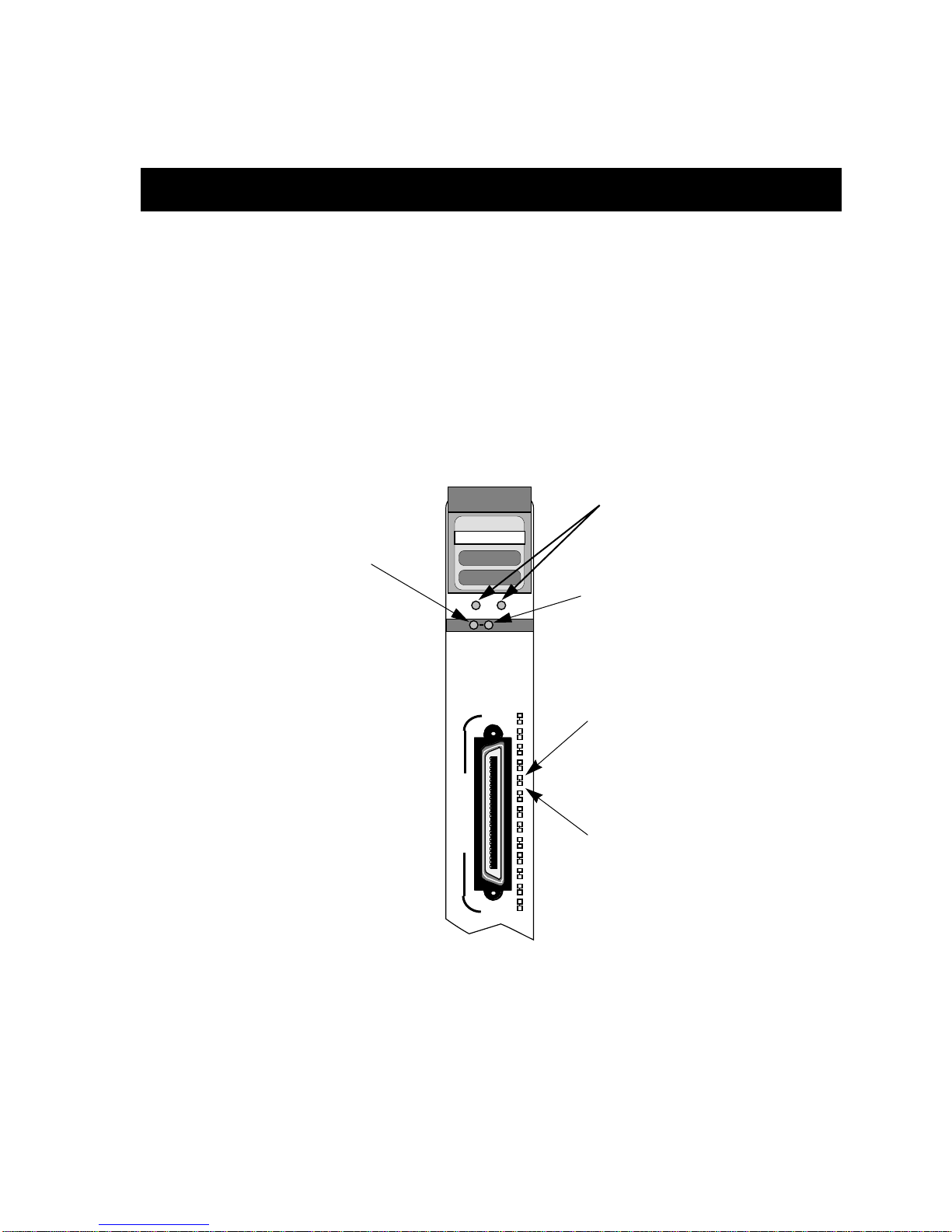
The front panel LANVIEW LEDs indicate the status of the module and may be
used as an aid in troubleshooting. Shown in Figure 4-1 are the LANVIEW LEDs of
the 9E423-36 module.
INB Receive
Chapter 4
System Status
ETHERNET
9E423-36
SMB CPU
INB
36
10
B
A
S
E
T
25
Figure 4-1. The LANVIEW LEDs
INB Transmit
Port
Receive
Port
Transmit
4-1
Page 28

LANVIEW LEDs
The functions of the two System Status LEDs, System Management Bus (SMB)
and CPU (Central Processing Unit), are listed in Table 4-1.
Table 4-1. System Status (SMB and CPU) LEDs
LED Color State Description
Green Functional Fully operational
Yellow Testing Power up testing
Yellow (Flashing) Crippled Not fully operational (i.e. one port may be bad)
Yellow/Green Booting Module is performing its boot process
Red Reset Module is resetting
Red (Flashing) Failed Fatal error
Off Power off Module powered off
The functions of the INB Receive LEDs are listed in Table 4-2.
Table 4-2. INB Receive LEDs
LED Color State
Green Link, no activity, port enabled
Green (Flashing) Link, port disabled
Yellow (Flashing) Link, activity, port enabled (Flashing to steady on indicates rate.)
Red No Link
The functions of the INB Transmit LEDs are listed in Table 4-3.
Table 4-3. INB Transmit LEDs
LED Color State
Green (Flashing) Activity, port enabled (Flashing to steady on indicates rate.)
Yellow (Flashing) Port in standby state
Red No Link
Off Link, No activity (port may be enabled or disabled)
4-2
Page 29

LANVIEW LEDs
The functions of the Port Receive LEDs are listed in Table 4-4.
Table 4-4. Port Receive LEDs
LED Color State
Green Link, no activity port enabled
Green (Flashing) Link, port disabled
Yellow (Flashing) Link, activity, port enabled (flashing to steady on indicates rate)
Off No link (port may be enabled or disabled)
The functions of the Port Transmit LEDs are listed in Table 4-5.
Table 4-5. Port Transmit LEDs
LED Color State
Green (Flashing) Data activity (flashing to steady on indicates rate)
Yellow (Flashing) Port in standby state
Red (Flashing) Collision (with collision rate)
Off No activity (port may be disabled or enabled)
4-3
Page 30

LANVIEW LEDs
4-4
Page 31

Specifications
Technical Specifications
CPU
Intel i960 RISC based microprocessor
Memory
16 Meg. Local RAM (expandable to 48 Meg.)
Chapter 5
4 Meg. Flash Memory (expandable to 32 Meg.)
2 Meg. Packet RAM
Standards
IEEE 802.1D
IEEE 802.3i 10BASE-T
Network Interfaces
Three RJ-21 Connectors
5-1
Page 32

Specifications
Safety
!
CAUTION
This equipment meets the safety requirements of:
UL 1950
CSA C22.2 No. 950
EN 60950
IEC 950
The EMI Requirements of:
• FCC Part 15 Class A
• EN 55022 Class A
• VCCI Class I
It is the responsibility of the person who sells the system to which the module will
be a part to ensure that the total system meets allowed limits of conducted and
radiated emissions.
The EMC requirements of:
• EN 50082-1
• IEC 801-2 ESD
• IEC 801-3 Radiated susceptibility
• IEC 801-4 EFT
Service
MTBF (MHBK-217E) >200,000 hrs.
MTTR <0.5 hr.
Physical
Dimensions
35.0 D x 44.0 H x 6.0 W centimeters
(13.8 D x 17.4 H x 1.2 W inches)
5-2
Page 33

Weight
Unit: 1.360.7 gr. (3 lbs.)
Shipping: 1.814.4 gr. (4 lbs.)
Environment
Operating Temperature 5 to 40° C
Storage Temperature -30 to 90° C
Relative Humidity 5% to 95% non-condensing
Specifications
5-3
Page 34

Specifications
5-4
 Loading...