

Page 1
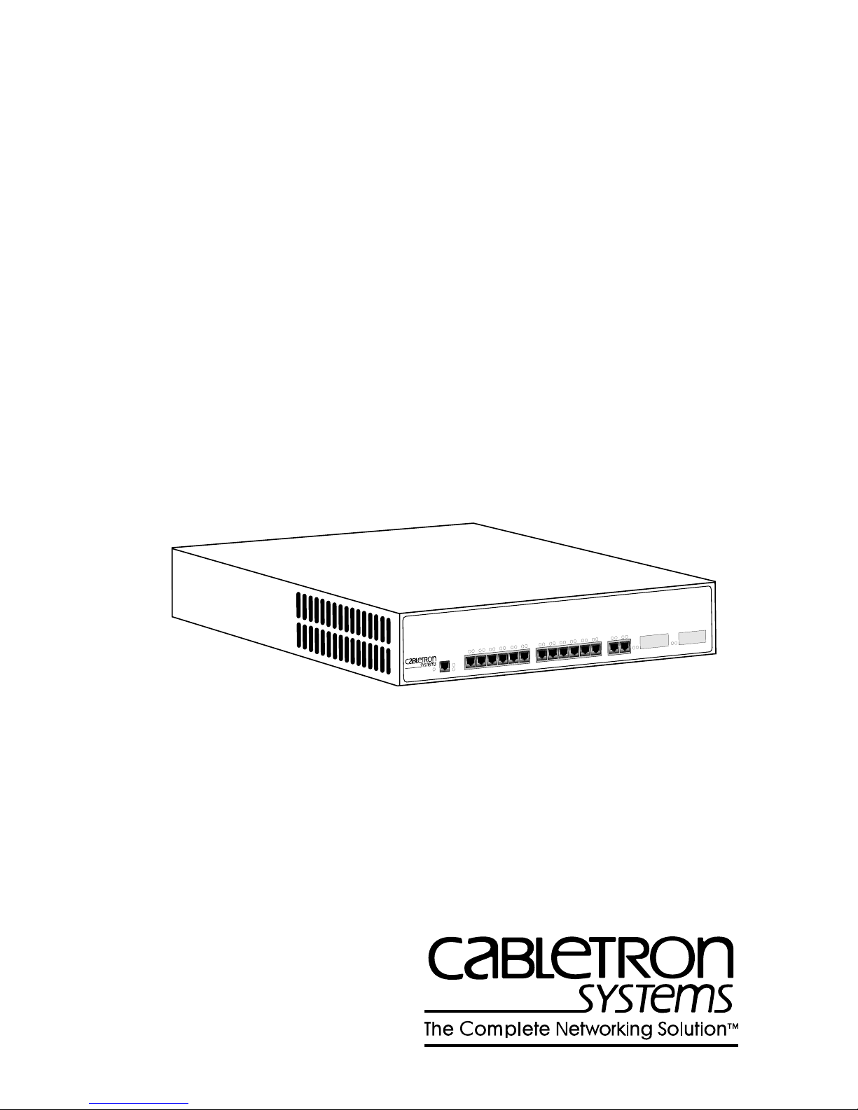
8H02-16 SmartSwitch 10/100
USER’S GUIDE
SmartSwitch 10/100
VIRTUAL NETWORKING
AST
F
ECURE
S
WITH
12X
11X
10X
9X
8X
7X
6X
5X
8H02-16
PWR
CPU
RESET
COM
4X
3X
2X
1X
MMAC
Smart
SWITCH
16
15
14X
13X
1742-00
Page 2

Page 3

Only qualified personnel should install the 8H02-16.
NOTICE
Cabletron Systems reserves the right to make changes in specifications and other information
contained in this document without prior notice. The reader should in all cases consult Cabletron
Systems to determine whether any such changes have been made.
The hardware, firmware, or software described in this manual is subject to change without notice.
IN NO EVENT SHALL CABLETRON SYSTEMS BE LIABLE FOR ANY INCIDENTAL,
INDIRECT, SPECIAL, OR CONSEQUENTIAL DAMAGES WHATSOEVER (INCLUDING BUT
NOT LIMITED TO LOST PROFITS) ARISING OUT OF OR RELATED TO THIS MANUAL OR
THE INFORMATION CONTAINED IN IT, EVEN IF CABLETRON SYSTEMS HAS BEEN
ADVISED OF, KNOWN, OR SHOULD HAVE KNOWN, THE POSSIBILITY OF SUCH
DAMAGES.
Copyright 1996 by Cabletron Systems, Inc., P.O. Box 5005, Rochester, NH 03866-5005
All Rights Reserved
Printed in the United States of America
Order Number: 9031742-02 August 1996
SPECTRUM, LANVIEW
FE-100FX, FE-100TX, S
All other product names mentioned in this manual may be trademarks or registered trademarks of
their respective companies.
, and
MMAC
ECUREFAST
are registered trademarks and
, and
SmartSwitch
are trademarks of Cabletron Systems, Inc.
Element Manager
,
8H02-16 User’s Guide i
Printed on Recycled Paper
Page 4

Notice
FCC NOTICE
This device complies with Part 15 of the FCC rules. Operation is subject to the following two
conditions: (1) this device may not cause harmful interference, and (2) this device must accept any
interference received, including interference that may cause undesired operation.
NOTE:
device, pursuant to Part 15 of the FCC rules. These limits are designed to provide reasonable
protection against harmful interference when the equipment is operated in a commercial environment.
This equipment uses, generates, and can radiate radio frequency energy and if not installed in
accordance with the operator’s manual, may cause harmful interference to radio communications.
Operation of this equipment in a residential area is likely to cause interference in which case the user
will be required to correct the interference at his own expense.
WARNING:
party responsible for compliance could void the user’s authority to operate the equipment.
This equipment has been tested and found to comply with the limits for a Class A digital
Changes or modifications made to this device which are not expressly approved by the
DOC NOTICE
This digital apparatus does not exceed the Class A limits for radio noise emissions from digital
apparatus set out in the Radio Interference Regulations of the Canadian Department of
Communications.
Le présent appareil numérique n’émet pas de bruits radioélectriques dépassant les limites applicables
aux appareils numériques de la class A prescrites dans le Règlement sur le brouillage radioélectrique
édicté par le ministère des Communications du Canada.
VCCI NOTICE
This equipment is in the 1st Class Category (information equipment to be used in commercial and/or
industrial areas) and conforms to the standards set by the Voluntary Control Council for Interference
by Information Technology Equipment (VCCI) aimed at preventing radio interference in commercial
and/or industrial areas.
Consequently , when used in a residential area or in an adjacent area thereto, radio interference may be
caused to radios and TV receivers, etc.
Read the instructions for correct handling.
ii 8H02-16 User’s Guide
Page 5

Notice
CABLETRON SYSTEMS, INC. PROGRAM LICENSE AGREEMENT
IMPORTANT:
This document is an agreement between you, the end user, and Cabletron Systems, Inc. (“Cabletron”)
that sets forth your rights and obligations with respect to the Cabletron software program (the
“Program”) contained in this package. The Program may be contained in firmware, chips or other
media. BY UTILIZING THE ENCLOSED PRODUCT, YOU ARE AGREEING TO BECOME
BOUND BY THE TERMS OF THIS AGREEMENT, WHICH INCLUDES THE LICENSE AND
THE LIMITATION OF WARRANTY AND DISCLAIMER OF LIABILITY. IF YOU DO NOT
AGREE TO THE TERMS OF THIS AGREEMENT , PR OMPTLY RETURN THE UNUSED
PRODUCT TO THE PLACE OF PURCHASE FOR A FULL REFUND.
Before utilizing this product, carefully read this License Agreement.
CABLETRON SOFTWARE PROGRAM LICENSE
1. LICENSE
package subject to the terms and conditions of this License Agreement.
You may not copy, reproduce or transmit any part of the Program except as permitted by the
Copyright Act of the United States or as authorized in writing by Cabletron.
2. OTHER RESTRICTIONS. You may not reverse engineer, decompile, or disassemble the
Program.
3. APPLICABLE LA W. This License Agreement shall be interpreted and governed under the laws
and in the state and federal courts of New Hampshire. You accept the personal jurisdiction and
venue of the New Hampshire courts.
. You have the right to use only the one (1) copy of the Program provided in this
EXCLUSION OF WARRANTY AND DISCLAIMER OF LIABILITY
1. EXCLUSION OF
writing, Cabletron makes no warranty, expressed or implied, concerning the Program (including
its documentation and media).
CABLETRON DISCLAIMS ALL WARRANTIES, OTHER THAN THOSE SUPPLIED TO
YOU BY CABLETRON IN WRITING, EITHER EXPRESSED OR IMPLIED, INCLUDING
BUT NOT LIMITED TO IMPLIED WARRANTIES OF MERCHANTABILITY AND
FITNESS FOR A PARTICULAR PURPOSE, WITH RESPECT TO THE PROGRAM, THE
ACCOMPANYING WRITTEN MA TERIALS, AND ANY A CCOMPANYING HARDW ARE.
2. NO LIABILITY FOR CONSEQUENTIAL DAMAGES. IN NO EVENT SHALL
CABLETRON OR ITS SUPPLIERS BE LIABLE FOR ANY DAMAGES WHATSOEVER
(INCLUDING, WITHOUT LIMITATION, DAMAGES FOR LOSS OF BUSINESS,
PROFITS, BUSINESS INTERRUPTION, LOSS OF BUSINESS INFORMATION, SPECIAL,
INCIDENTAL, CONSEQUENTIAL, OR RELIANCE DAMAGES, OR OTHER LOSS)
ARISING OUT OF THE USE OR INABILITY TO USE THIS CABLETRON PRODUCT,
EVEN IF CABLETRON HAS BEEN ADVISED OF THE POSSIBILITY OF SUCH
DAMAGES. BECAUSE SOME STATES DO NOT ALLOW THE EXCLUSION OR
LIMITATION OF LIABILITY FOR CONSEQUENTIAL OR INCIDENTAL DAMAGES, OR
ON THE DURATION OR LIMITATION OF IMPLIED WARRANTIES, IN SOME
INSTANCES THE ABOVE LIMITATIONS AND EXCLUSIONS MAY NOT APPLY TO
YOU.
WARRANTY. Except as may be specifically provided by Cabletron in
8H02-16 User’s Guide iii
Page 6

Notice
UNITED STATES GOVERNMENT RESTRICTED RIGHTS
The enclosed product (a) was developed solely at private expense; (b) contains “restricted computer
software” submitted with restricted rights in accordance with Section 52227-19 (a) through (d) of the
Commercial Computer Software - Restricted Rights Clause and its successors, and (c) in all respects
is proprietary data belonging to Cabletron and/or its suppliers.
For Department of Defense units, the product is licensed with “Restricted Rights” as defined in the
DoD Supplement to the Federal Acquisition Regulations, Section 52.227-7013 (c) (1) (ii) and its
successors, and use, duplication, disclosure by the Government is subject to restrictions as set forth in
subparagraph (c) (1) (ii) of the Rights in Technical Data and Computer Software clause at
252.227-7013. Cabletron Systems, Inc., 35 Industrial Way, Rochester, New Hampshire 03867-0505.
iv 8H02-16 User’s Guide
Page 7

CONTENTS
CHAPTER 1 INTRODUCTION
1.1 Using This Guide.........................................................................1-1
1.2 Structure of This Guide................................................................1-2
1.3 8H02-16 Overview.......................................................................1-3
1.4 Local Management Features.......................................................1-6
1.5 Optional Features........................................................................1-6
1.6 Document Conventions...............................................................1-7
1.7 Getting Help.................................................................................1-8
1.8 Related Manuals..........................................................................1-9
CHAPTER 2 NETWORK REQUIREMENTS
2.1 Network Requirements................................................................2-1
2.2 100BASE-TX Network Cable Lengths.........................................2-4
CHAPTER 3 INSTALLATION
3.1 Required Tools............................................................................3-1
3.2 Unpacking the 8H02-16...............................................................3-1
3.3 8H02-16 Options ......................................................................... 3-2
3.4 Installing the 8H02-16..................................................................3-2
3.5 Connecting to the Network..........................................................3-6
CHAPTER 4 TROUBLESHOOTING
4.1 Using LANVIEW..........................................................................4-1
4.2 FE-100TX LED............................................................................4-3
4.3 Troubleshooting Checklist...........................................................4-5
4.4 Using the RESET Button.............................................................4-6
CHAPTER 5 COM PORT AND TELNET CONNECTIONS
5.1 Local Management Terminal Connection....................................5-1
5.2 Configuring the Terminal.............................................................5-1
5.3 Connecting a Management Terminal to the 8H02-16..................5-3
5.4 Connecting the UPS to the 8H02-16...........................................5-3
5.5 Runtime IP Address Discovery....................................................5-4
5.6 COM Port and Telnet Connections..............................................5-4
8H02-16 User’s Guide v
Page 8

Contents
CHAPTER 6 LOCAL MANAGEMENT
6.1 Overview......................................................................................6-1
6.2 Local Management Keyboard Conventions.................................6-2
6.3 Accessing Local Management.....................................................6-3
6.4 Device Menu Screen....................................................................6-6
6.5 Device Configuration Menu Screen .............................................6-8
6.6 General Configuration Screen ...................................................6-10
6.7 SNMP Community Names Screen.............................................6-23
6.8 SNMP Traps Screen..................................................................6-26
6.9 Configuring the Trap Table ........................................................6-27
6.10 Bridge Configuration Screen......................................................6-28
6.11 Device Specific Configuration Menu Screen..............................6-31
6.12 Full Duplex Configuration Screen ..............................................6-33
6.13 System Resources Screen ........................................................6-36
6.14 High Speed Interface Configuration Screen ..............................6-39
6.15 Flash Download Screen.............................................................6-44
6.16 Clear NVRAM Screen................................................................6-48
6.17 Port Redirect Function Screen...................................................6-50
6.18 Device Statistics Menu Screen ..................................................6-53
6.19 Bridge Statistics Screen.............................................................6-54
6.20 Port Statistics Screen.................................................................6-55
6.21 Network Tools............................................................................6-58
APPENDIX A SPECIFICATIONS
A.1 Device Specifications.................................................................. A-1
A.2 Physical Properties ..................................................................... A-1
A.3 Electrical Specifications .............................................................. A-1
A.4 Environmental Requirements...................................................... A-1
A.5 Input/Output Ports....................................................................... A-2
A.6 COM Port/Pin Assignments ........................................................ A-2
A.7 Agency Approvals....................................................................... A-3
APPENDIX B FE-100TX AND FE-100FX SPECIFICATIONS
B.1 FE-100TX.................................................................................... B-1
B.2 FE-100FX.................................................................................... B-2
vi 8H02-16 User’s Guide
Page 9

Contents
APPENDIX C OPTIONAL INSTALLATIONS AND
MODE SWITCH BANK SETTINGS
C.1 Required Tools............................................................................C-1
C.2 Removing the Chassis Cover......................................................C-2
C.3 Setting the Mode Switch..............................................................C-4
C.4 Installing Optional Fast Ethernet Interface Modules....................C-6
INDEX
8H02-16 User’s Guide vii
Page 10

Contents
viii 8H02-16 User’s Guide
Page 11

CHAPTER 1
INTRODUCTION
Welcome to the Cabletron Systems
User’s Guide
. This guide describes the 8H02-16 SmartSwitch and
8H02-16 SmartSwitch 10/100
provides information concerning network requirements, installation,
troubleshooting, and the use of Local Management for device local
control and management.
1.1 USING THIS GUIDE
Read through this guide completely to understand the 8H02-16
SmartSwitch features, capabilities, and Local Management functions. A
general working knowledge of Ethernet and IEEE 802.3 type data
communications networks and their physical layer components is helpful
when using Local Management.
In this document, the 8H02-16 SmartSwitch is referred to as
NOTE
either the “8H02-16” or the “device.”
8H02-16 User’s Guide 1-1
Page 12

Chapter 1:
Introduction
1.2 STRUCTURE OF THIS GUIDE
This guide is organized as follows:
Chapter 1,
Introduction
, outlines the contents of this manual and briefly
describes the 8H02-16 features. Directions about how to receive
additional help and a list of related manuals are also included.
Chapter 2,
Network Requirements
, explains the network requirements
to consider before installing the 8H02-16.
Chapter 3,
Installation
, provides instructions on how to install the unit
and connect segments to the device.
Chapter 4,
Troubleshooting
, details the 8H02-16 LANVIEW LEDs that
enable you to quickly diagnose network/operational problems.
Chapter 5,
COM Port and Telnet Connections
, describes how to attach
a management console to the 8H02-16 to access Local Management (LM)
or attach an uninterruptible power supply (UPS).
Chapter 6,
Local Management
, describes how to access Local
Management and use the Local Management screens to manage the
8H02-16.
Appendix A,
Specifications
, contains information on functionality and
operating specifications, connector pinouts, environmental requirements,
and physical properties.
Appendix B,
FE-100TX and FE-100FX Specifications
, contains
information about FE-100TX pinouts and information concerning cable
types used with the FE-100FX.
Appendix C,
Optional Installations and Mode Switch Bank Settings
,
describes how to remove the top cover to gain access to and set the Mode
Switch Bank, and install optional Fast Ethernet Interface Modules.
1-2 8H02-16 User’s Guide
Page 13
8H02-16 Overview
1.3 8H02-16 OVERVIEW
The 8H02-16 is a standalone 16-port high-speed network switch device
that supports traditional switching (bridging). Ports 15 and 16 support
optional Fast Ethernet Interface Modules and can provide uplinks to
100BASE-TX or 100BASE-FX fast Ethernet networks.
The 8H02-16 is used to connect individual high-bandwidth user devices,
such as workstations, and provide a central switching point for multiple
Ethernet segments built using devices such as Cabletron Systems
HUBSTACK or other third party stackable devices.
The 8H02-16 is a tabletop unit that can also be installed in a standard
19-inch rack using the supplied rack mounting hardware.
The 8H02-16 has a universal ac power supply with automatic voltage
sensing that allows operation using 100–125 or 200–250 Vac, 50/60 Hz.
1.3.1 8H02-16 Features
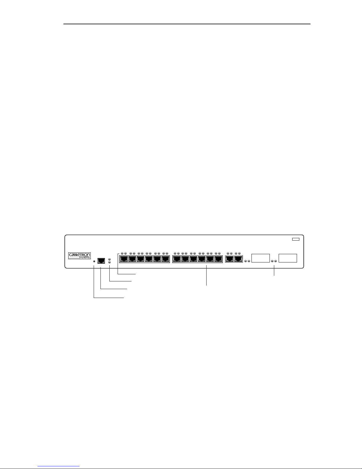
The 8H02-16, shown in Figure 1-1, has the features listed below.
SmartSwitch 10/100
WITH
S
ECURE
F
AST VIRTUAL NETWORKING
PWR
8H02-16
RESET
COM
CPU
1X 2X 3X 4X 5X 6X 7X 8X 9X 10X 11X 12X 13X 14X 15 16
Port Status LEDs
System LEDs
COM Port
RESET Button
Network Ports 1-14
Fast Ethernet Interface
Module Ports 15 & 16
Figure 1-1 The 8H02-16
• Intel i960 RISC processor control
• 14 Port High-Speed Workgroup Switch with two optional ports for
Fast Ethernet Interface Modules providing high speed uplinks to
100 Mbps fast Ethernet technologies
MMAC
Smart
SWITCH
174248
8H02-16 User’s Guide 1-3
Page 14

Chapter 1:
Introduction
• Full Duplex Switched Ethernet (FDSE) support for 20 Mbps links to
bandwidth intensive users/servers
• Runtime IP Address Discovery that allows the 8H02-16 to send out a
RARP or BootP request to determine its IP address
• Manageable using Simple Network Management Protocol (SNMP)
and Remote Monitoring (RMON)
• Support for traditional switching services as well as for Cabletron
Systems S
ECUREFAST
Switching Virtual Network technology
• Possible linking of existing stackable or third party hubs to 100 Mbps
Fast Ethernet backbones
• IEEE 802.3 compatibility with support for IEEE 802.1d and DEC
Spanning Tree Algorithms
• LANVIEW Diagnostic LEDs
1.3.2 Connectivity
The 8H02-16 connects to Ethernet networks or workstations through
fourteen RJ45 ports on the front panel. These ports support Unshielded
Twisted Pair (UTP) and Shielded Twisted Pair (STP) cables at lengths up
to 100 meters. The ports are IEEE 802.3 10BASE-T compliant.
The 8H02-16 has two front panel slots (ports 15 and 16) for optional Fast
Ethernet Interface Modules to support an uplink to 100 Mbps Ethernet
backbones or a high speed connection to a local server.
1.3.3 Full Duplex Switched Ethernet
Each switched Ethernet port supports full wire-speed Ethernet
communications and can be configured to operate in Full Duplex
Switched Ethernet mode.
1-4 8H02-16 User’s Guide
Page 15

8H02-16 Overview
1.3.4 Management
Management of the 8H02-16 is accomplished using Local Management
tools or remote SNMP management stations. Out-of-band local
management is provided through the RS232 COM port on the front panel
using a VT100 terminal or a VT100 terminal emulator. In-band remote
management is possible through any SNMP compliant Network
Management Software.
1.3.5 Traditional Switching
The 8H02-16 provides traditional Switching or S
ECUREFAST
Switching
Virtual Network Services between all of the front panel interfaces
including the optional ports 15 and 16.
Through Cabletron Systems Synthesis framework, the 8H02-16 supports
operations in traditional Switching mode or S
mode. S
ECUREFAST
Switching allows for future migration to Virtual
ECUREFAST
Switching
Network technologies without requiring the replacement of existing
equipment.
1.3.6 Standards Compatibility
The 8H02-16 provides IEEE 802.1d Spanning Tree Algorithm (STA)
support to enhance the overall reliability of the network and protect
against “loop” conditions. The 8H02-16 supports a wide variety of
industry standard MIBs including RFC 1213 (MIB II), RFC 1271
(RMON), RFC 1371 (RS232 MIB), RFC 1493 (Bridge MIB) and RFC
1354 (FIB MIB). A full suite of Cabletron Systems Enterprise MIBs
provide a wide array of statistical information to enhance troubleshooting.
1.3.7 LANVIEW Diagnostic LEDs
LANVIEW diagnostic LEDs serve as an important troubleshooting aid by
providing an easy way to observe the status of indi vidual ports and ov erall
network operations. Chapter 4 provides details about the 8H02-16
LANVIEW LEDs.
8H02-16 User’s Guide 1-5
Page 16

Chapter 1:
Introduction
1.4 LOCAL MANAGEMENT FEATURES
Local Management provides the tools that allow management of the
8H02-16 and any of the optional Fast Ethernet Interface Modules
installed as ports 15 and 16. It also allows the following tasks to be
performed:
• Assign an IP address and subnet mask to the 8H02-16.
• Select a default gateway and default interface.
• Control local and remote access.
• Designate workstations to receive SNMP traps from the 8H02-16.
• Configure module specific SNMP MIB objects including the IETF
Bridge MIB objects and many of the RMON MIB objects.
Chapter 6 provides detailed information about Local Management.
1.5 OPTIONAL FEATURES
The two optional Memory Upgrade Kits for the 8H02-16 SmartSwitch
are listed below:
• The 8H02-16-MEM-UGK Memory Upgrade Kit provides an 8 MB
DRAM SIMM that allows the 8H02-16 to run SFS (Secure Fast
Switching) and all groups of RMON.
• The 8H02-8D/4F-ADV Advanced Memory Upgrade Kit provides
8 MB DRAM, 4 MB of FLASH with a preloaded image, and image
diskettes that allows the 8H02-16 to run VLAN (Virtual Local Area
Network), SFS, and RMON.
1-6 8H02-16 User’s Guide
Page 17
Document Conventions
• Cabletron Systems provides Fast Ethernet Interface Modules to
support uplinks to 100 Mbps Ethernet backbones or high speed
connections to local servers. The F ast Ethernet Interf ace Modules are
listed in Table 1-1.
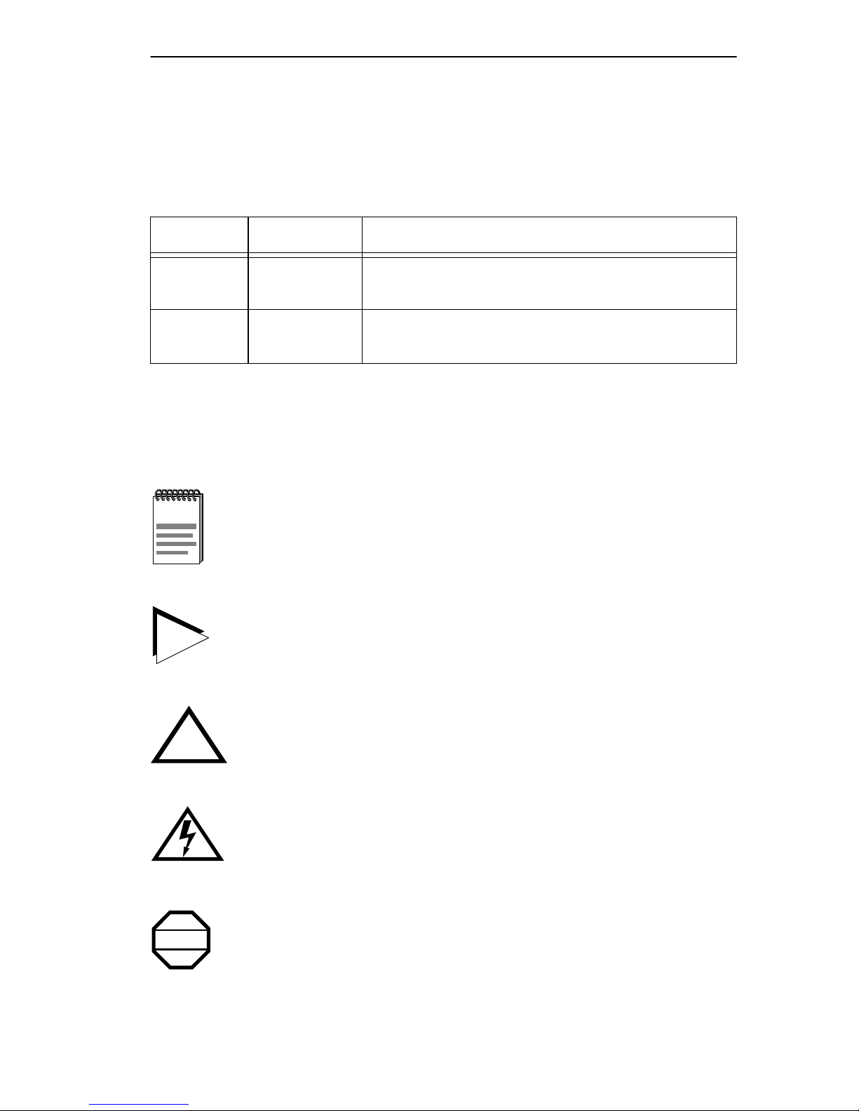
Table 1-1 Fast Ethernet Interface Modules
P/N Description Application
FE-100TX
FE-100FX
Uses RJ45
connector
Uses SC
connector
Supports Unshielded Twisted Pair (UTP) cabling.
Supports multimode fiber optic cabling.
1.6 DOCUMENT CONVENTIONS
The following conventions are used throughout this document:
Note
symbol. Calls the reader’s attention to any item of
NOTE
TIP
information that may be of special importance.
Tip
symbol. Conveys helpful hints concerning procedures or
actions.
Caution
!
CAUTION
damage to the equipment.
Electrical Hazard Warning
that could result in personal injury or death due to an electrical
hazard.
Warning
WARNING
personal injury or death.
8H02-16 User’s Guide 1-7
symbol. Contains information essential to avoid
symbol. Warns against an action
symbol. Warns against an action that could result in
Page 18

Chapter 1:
Introduction
1.7 GETTING HELP
If you need additional support related to this device, or if you have any
questions, comments, or suggestions concerning this manual, contact
Cabletron Systems Technical Support:
Phone (603) 332-9400
Monday – Friday; 8 A.M. – 8 P.M. Eastern Time
CompuServe GO CTRON from any ! prompt
Internet mail [email protected]
FTP ctron.com (134.141.197.25)
Login
Password
BBS (603) 335-3358
Modem setting 8N1: 8 data bits, 1 stop bit, No parity
anonymous
your email address
For additional information about Cabletron Systems products, visit our
World Wide Web site: http://www .cabletron.com/
Before calling Cabletron Systems Technical Support, have the following
information ready:
• A description of the failure
• A description of any action(s) already taken to resolve the problem
(e.g., changing mode switches, rebooting the unit, etc.)
• A description of your network environment (layout, cable type, etc.)
• Network load and frame size at the time of trouble (if known)
• The serial and revision numbers of all Cabletron Systems products in
the network
• The device history (i.e., have you returned the device before, is this a
recurring problem, etc.)
• Any previous Return Material Authorization (RMA) numbers
1-8 8H02-16 User’s Guide
Page 19

Related Manuals
1.8 RELATED MANUALS
The following manuals may help the user to control and manage the
8H02-16 using SNMP network management systems:
Cabletron Systems
Cabletron Systems
Applications
(SPMA) products
SPECTRUM Element Manager for Windows
SPECTRUM and SPECTRUM Portable Management
Third Party SNMP compliant Network Management Packages
8H02-16 User’s Guide 1-9
Page 20

Chapter 1:
Introduction
1-10 8H02-16 User’s Guide
Page 21

CHAPTER 2
NETWORK REQUIREMENTS
This chapter contains general networking guidelines. Before attempting
to use the 8H02-16 or to install a Fast Ethernet Interface Module
(FE-100TX or FE-100FX), review the requirements and specifications
outlined in this chapter.
2.1 NETWORK REQUIREMENTS
The network installation must meet the guidelines included in this chapter
to ensure satisfactory performance of this equipment. Failure to follow
these guidelines may produce poor network performance.
Refer to the following sections that apply to your specific network
configuration.
2.1.1 10BASE-T Twisted Pair Network
When connecting a 10BASE-T twisted pair segment to any of the
8H02-16 ports (Interfaces 1 through 14), ensure the network meets the
following requirements:
Length
The IEEE 802.3 standard for 10BASE-T requires that 10BASE-T devices
transmit over a 100 meter (328 foot) link using 22–24 AWG Unshielded
Twisted Pair (UTP) wire. However, cable quality largely determines
maximum link length. If you use high quality, low attenuation cable, you
can achieve link lengths of up to 200 meters. Cable delay limits the
maximum link length to 200 meters.
Losses introduced by connections at punch-down blocks and
NOTE
other equipment reduce total segment length. For each
connector or patch panel in the link, subtract 12 meters from
the total length of the cable.
8H02-16 User’s Guide 2-1
Page 22

Chapter 2: Network Requirements
Impedance
Cabletron Systems 10BASE-T twisted pair products work on twisted pair
cable with 75 to 165 ohms impedance. UTP cables typically have an
impedance from 85 to 110 ohms. Shielded twisted pair cables, such as
IBM Type 1 cable with an impedance of 150 ohms may also be used.
Temperature
Multi-pair PVC 24 AWG telephone cables typically have an attenuation
of approximately 8–10 dB/100 m at 20°C (68°F). The attenuation of PVC
insulated cable varies significantly with temperature. At temperatures
greater than 40°C (104°F), use plenum-rated cable to ensure that
attenuation remains within specification.
2.1.2 100BASE-TX Twisted Pair Network
The 8H02-16 with an FE-100TX installed in ports 15 or 16 provides an
RJ45 connection that supports UTP cabling. The device at the other end
of the twisted pair segment must meet IEEE 802.3u 100BASE-TX
specifications for the devices to operate at 100 Mbps. Use Category 5
UTP cabling for networks operating at 100 Mbps. Use Category 3, 4, or 5
UTP cabling for networks operating at 10 Mbps.
The 8H02-16 with an FE-100TX installed is capable of
NOTE
operating at either 10 or 100 Mbps. The FE-100TX senses the
speed of the other device and adjusts its speed accordingly.
When connecting a 100BASE-TX twisted pair segment to port 15 or 16
with an FE-100TX interface module, the network must meet the
following requirements:
Length
The IEEE 802.3u standard for 100BASE-TX requires that 100BASE-TX
devices be capable of transmitting over a 100 meter (328 foot) link using
Category 5 UTP cable.
The IEEE 802.3 standard for 10BASE-T requires that 10BASE-T devices
be capable of transmitting over a 100 meter (328 foot) link using
Category 3, 4, or 5 UTP cable.
2-2 8H02-16 User’s Guide
Page 23

Network Requirements
Propagation Delay
Propagation delay is the amount of time it takes data to travel from the
sending device to the receiving device.
Total propagation delay allowed for a 100BASE-TX (100 Mbps) network
is 256 bit times or 2.56 microseconds (2.56 µs). If the total propagation
delay between any two nodes on a 100BASE-TX network exceeds
2.56 µs, then use bridges or other devices to further segment the network.
Total propagation delay allowed for a 10BASE-T (10 Mbps) network is
256 bit times or 25.6 µs. If the total propagation delay between any two
nodes on a 10BASE-T network e xceeds 25.6 µs, then use bridges or other
devices to further segment the network.
Temperature
The attenuation of PVC insulated cable varies significantly with
temperature. At temperatures greater than 40°C (104°F), use plenum rated
cables to ensure that cable attenuation remains within specification.
2.1.3 100BASE-FX Fiber Optic Network
Ports 15 and 16 of the 8H02-16 support the Cabletron Systems FE-100FX
fiber optic interface module. The FE-100FX meets the IEEE 802.3u
standard. When connecting a fiber optic segment to the 8H02-16, the
network must meet the following requirements:
Cable Loss
T est the fiber optic cable with a fiber optic attenuation test set adjusted for
an 850 nm wavelength. This test verifies that the signal loss is within an
acceptable level. The maximum loss for a multimode cable is 11.0 dB.
Fiber Optic Budget and Propagation Delay
Determine the maximum fiber optic cable length by calculating the fiber
optic budget delay and total network propagation before fiber optic cable
runs are incorporated in any network design.
Fiber optic budget is the combination of the optical loss due to the fiber
optic cable, in-line splices, and fiber optic connectors.
8H02-16 User’s Guide 2-3
Page 24

Chapter 2: Network Requirements
Propagation delay (collision delay) is the amount of time it takes data to
travel from the sending device to the receiving device. Total propagation
delay allowed for the entire network is 256 bit times (2.56 µs). If the total
propagation delay between any two nodes on the network exceeds
2.56 µs, then use bridges or other devices to further segment the network.
2.2 100BASE-TX NETWORK CABLE LENGTHS
This section details the maximum network cable lengths specified by the
IEEE 802.3u standard. As stated in the previous sections, the physical size
of the network is limited primarily by propagation delay. The total
propagation delay cannot exceed 256 bit times or 2.56 µs.
A 100BASE-TX/FX network might use all copper (UTP) links, all fiber
links or a combination of both. The maximum length of any segment is
determined by the types and combination of links and by the type of
repeater (if any) between segments. IEEE 802.3u standards specify two
repeater classes (Class 1 and Class 2) and the maximum cable lengths for
each media type.
If this device is being installed in a 100BASE-TX/FX environment with
repeaters, use the repeater instruction manual to determine the maximum
cable lengths when laying out your network.
UTP Maximum Cable Lengths
An Unshielded Twisted Pair copper segment in a 100BASE-TX
environment may be no more than 100 meters in length.
The maximum length of a UTP segment may be no more than
!
CAUTION
Multimode Fiber Cable Lengths
100 meters.
The maximum length of a 100BASE-FX segment may be no more than
412 meters between Data Terminal Equipment (DTE to DTE) in half
duplex mode or 2 km (DTE to DTE) in full duplex mode.
2-4 8H02-16 User’s Guide
Page 25

CHAPTER 3
INSTALLATION
Only qualified personnel should install the 8H02-16.
This chapter covers the following items:
• Required tools
• Unpacking the 8H02-16
• Installing the 8H02-16 on a shelf or into a standard rack
• Connecting to the power source
• Connecting to the network
3.1 REQUIRED T OOLS
A Phillips screwdriver is required to install the equipment.
3.2 UNPACKING THE 8H02-16
To unpack the shipment, proceed as follows:
1. Carefully remove the 8H02-16 from the shipping box. Save all
shipping material in case any items need to be returned.
2. Visually inspect the 8H02-16 and any optional equipment.
3. If there are any signs of damage, contact Cabletron Systems Technical
Support. Refer to Section 1.7, Getting Help, for details.
8H02-16 User’s Guide 3-1
Page 26
Chapter 3: Installation
3.3 8H02-16 OPTIONS
Install the options first before proceeding to Section 3.4.
NOTE
If the 8H02-16 is to be installed with optional Fast Ethernet Interface
Modules, refer to Appendix C for installation instructions. For more
information on the two Fast Ethernet Interface Modules and the two
optional memory kits, refer to Section 1.5, Optional Features.
3.4 INSTALLING THE 8H02-16
The 8H02-16 may be installed on a tabletop, shelf, or in a 19-inch rack.
Refer to Section 3.4.1 for information concerning a tabletop or shelf
installation. Section 3.4.2 describes the rackmount installation.
3.4.1 Tabletop or Shelf Installation
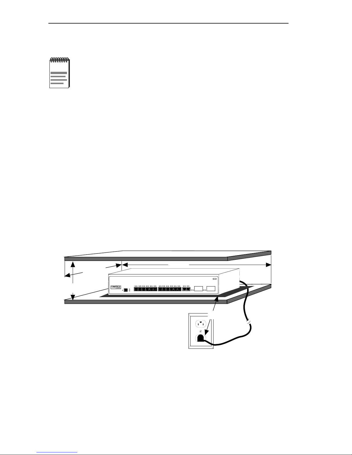
This section provides guidelines for installation on a tabletop or shelf.
B
SmartSwitch 10/100
WITH S
A
8H02-16
A = 15 cm (6 in)
B = 46 cm (18 in)
C = 53 cm (21 in)
D = 213 cm (7 ft)
Figure 3-1 Tabletop or Shelf Installation
ECURE
F
AST VIRTUAL NETWORKING
RESET
PWR
CPU
1X 2X 3X 4X 5X 6X 7X 8X 9X 10X 11X 12X 13X 14X 15 16
COM
C
MMAC
Smart
SWITCH
D
1742_06
Proceed to Section 3.4.3 for instructions about connecting power.
3-2 8H02-16 User’s Guide
Page 27

Installing the 8H02-16
3.4.2 Rackmount Installation
To install the 8H02-16 in a 19-inch rack, Cabletron Systems includes an
accessory kit containing the rackmount brackets, mounting screws, and a
strain-relief bracket for cable management.
Before installing the 8H02-16 into a rack, ensure that the rack
WARNING
Tabletop and shelf installations must be within reach of the network
cabling and meet the requirements listed below:
• Locate the 8H02-16 within seven feet of an appropriate grounded
power receptacle that meets the power supply requirements listed in
Appendix A, Specifications.
supports the device(s) without compromising the stability of the
rack. Otherwise, personal injury and/or equipment damage
may result.
• Maintain a temperature of between 5°C (41°F) and 40°C (104°F) at
the installation site with fluctuations of less than 10°C per hour.
To ensure proper ventilation and prevent overheating, leave a
!
CAUTION
minimum clearance space of 5.1 cm (2.0 in) at the left, right
and rear of the 8H02-16.
8H02-16 User’s Guide 3-3
Page 28
Chapter 3: Installation
Attaching the Strain-Relief Bracket
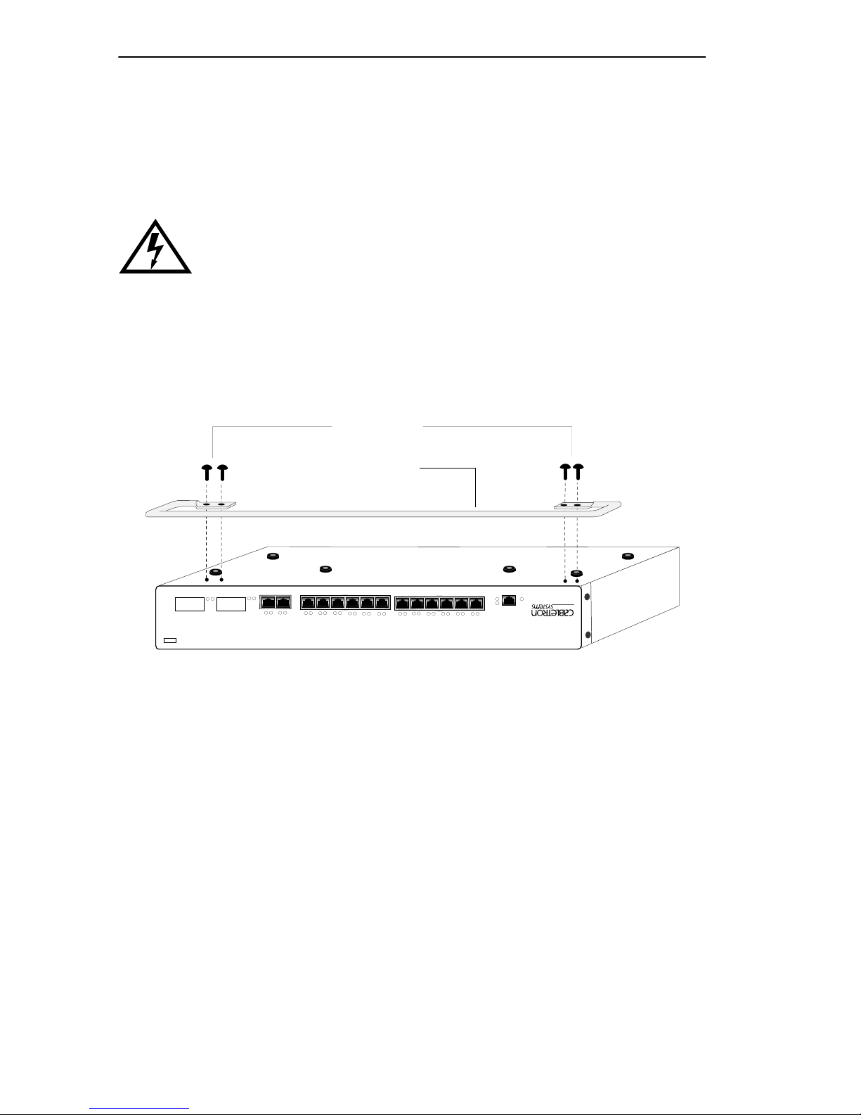
Attach the strain-relief bracket to the front of the 8H02-16 as follows:
1. Locate the strain-relief bracket and four 8-32 x 3/8-inch pan-head
screws in the rackmount kit.
Do not attempt to attach the strain-relief bracket with screws
other than the 8-32 x 3/8-inch screws included with the
8H02-16. Use of longer screws may damage the unit or cause
electrical shock.
2. Attach the strain-relief bracket to the bottom of the 8H02-16 using the
four 8-32 x 3/8-inch pan-head screws (Figure 3-2).
Screws (4)
MMAC
SWITCH
Smart
Strain-Relief Bracket
COM
1X 2X 3X 4X 5X 6X 7X 8X 9X 10X 11X 12X 13X 14X 15 16
RESET
CPU
PWR
AST VIRTUAL NETWORKING
S
ECURE
F
174247
8H02-16
WITH
SmartSwitch 10/100
Figure 3-2 Attaching the Strain-Relief Bracket
3-4 8H02-16 User’s Guide
Page 29
Installing the 8H02-16
Rack Mounting the 8H02-16
Proceed as follows to install the 8H02-16 into a 19-inch rack.
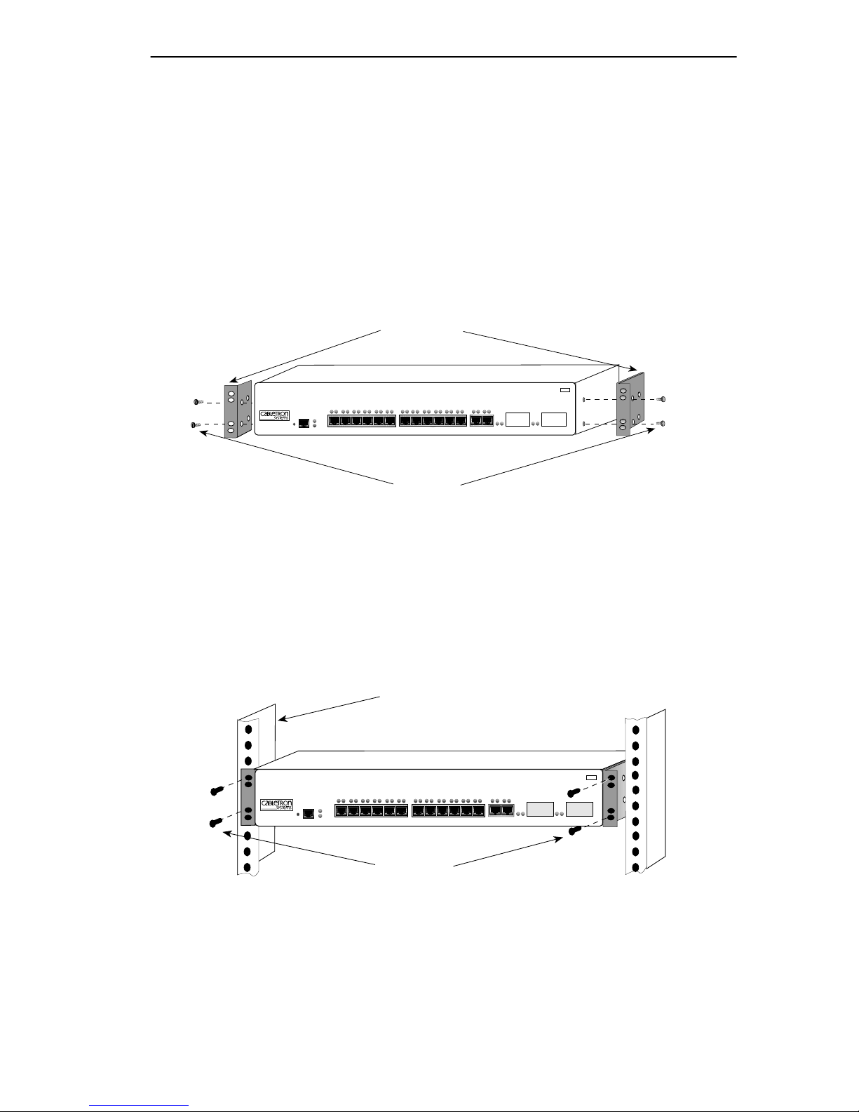
1. Remove and discard the four cover screws (two from each side)
located along the front edges of each side of the 8H02-16.
2. Locate the four 6-32 x 3/8-inch flat head cover replacement screws in
the rackmount kit. Use these screws to attach the rackmount brackets
to the 8H02-16 as shown in Figure 3-3.
Rackmount
Brackets (2)
SmartSwitch 10/100
WITH
S
ECURE
F
AST VIRTUAL NETWORKING
RESET
8H02-16
COM
PWR
CPU
1X 2X 3X 4X 5X 6X 7X 8X 9X 10X 11X 12X 13X 14X 15 16
Screws (4)
MMAC
Smart
SWITCH
1742-04
Figure 3-3 Installing the Rackmount Brackets
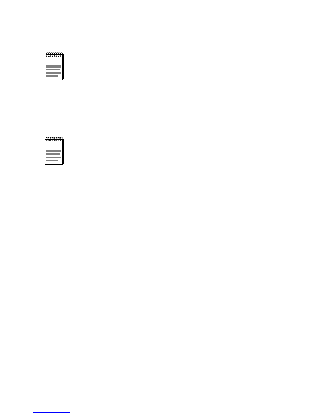
3. With the mounting brackets installed, position the 8H02-16 between
the vertical frame members of the 19-inch rack and fasten it securely
with mounting screws as shown in Figure 3-4.
19-Inch Rack
SmartSwitch 10/100
WITH S
ECURE
F
AST VIRTUAL NETWORKING
PWR
CPU
RESET
8H02-16
COM
1X 2X 3X 4X 5X 6X 7X 8X 9X 10X 11X 12X 13X 14X 15 16
MMAC
Smart
SWITCH
Figure 3-4 Installing the 8H02-16 in a Rack
8H02-16 User’s Guide 3-5
Screws (4)
1742-03
Page 30
Chapter 3: Installation
3.4.3 Connecting to the Power Source
The 8H02-16 has a power supply with automatic voltage
NOTE
To connect the 8H02-16 to a power source, proceed as follows:
1. Plug the power cord into a grounded wall outlet. The POWER LED
turns ON (green) and the CPU LED turns ON (green) briefly.
NOTE
sensing that allows connection to power sources ranging from
100–125 Vac or 200–250 Vac, 50/60 Hz.
It takes approximately one minute for the 8H02-16 to boot up.
2. Observe the LANVIEW LEDs. After boot up, the CPU LED becomes
solid green. If the CPU LED is not solid green, check the power cord
connection and power source. If the CPU LED is still not solid green
after approximately one minute, contact Cabletron Systems Technical
Support. Refer to Section 1.7, Getting Help, for details.
3.5 CONNECTING TO THE NETWORK
This section provides the procedures for connecting UTP and multimode
fiber optic segments from the network or other devices to the 8H02-16.
Ports 1 through 14 on the 8H02-16 have RJ45 connectors for UTP
connections. Ports 15 and 16 support FE-100TX or FE-100FX Fast
Ethernet Interface Modules. The FE-100TX has an RJ45 connector for a
UTP cable connection. The FE-100FX has an SC style connector for a
multimode fiber optic cable connection.
Refer to Section 3.5.1 to make UTP connections to ports 1 through 14.
Refer to Section 3.5.2 to make a UTP connection to an FE-100TX.
Refer to Section 3.5.3 to make a fiber optic connection to an FE-100FX.
3-6 8H02-16 User’s Guide
Page 31
Connecting to the Network
3.5.1 Connecting UTP Cables to Ports 1 Through 14
Before connecting a segment to the 8H02-16, check each end of the
segment to verify wire crossover.
To establish a link, you must have an odd number of
!
CAUTION
Connect a twisted pair segment to the 8H02-16 as follows:
1. Ensure that the device at the other end of the segment is connected to
the segment and is powered ON.
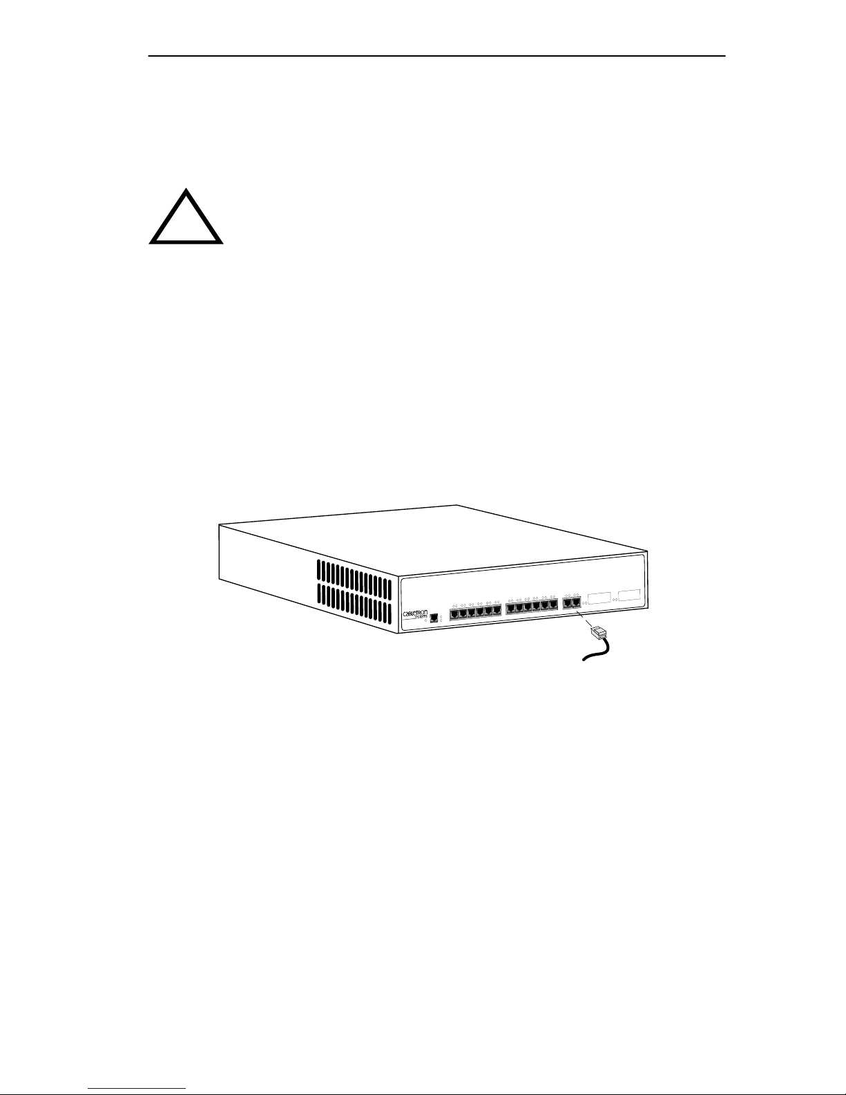
2. Refer to Figure 3-5. Connect the twisted pair segment to the 8H02-16
by inserting the RJ45 connector on the twisted pair segment into the
desired RJ45 port (ports 1 through 14).
crossovers (preferably one) between 10BASE-T devices of the
same type (i.e., from repeater to repeater or transceiver to
transceiver).
.
MMAC
Smart
SmartSwitch 10/100
VIRTUAL NETWORKING
AST
F
ECURE
S
WITH
RESET
COM
8H02-16
PWR
CPU
3X
2X
1X
8X
7X
6X
5X
4X
13X
12X
11X
10X
9X
SWITCH
16
15
14X
1742-09
Figure 3-5 8H02-16 Twisted Pair Connection
3. Verify that a Link exists by checking that the port RX LED is on
(flashing green or yellow or on solid green). If the RX LED is off,
perform the following steps until it is on:
a. Check that the 10BASE-T device at the other end of the twisted
pair segment is ON and connected to the segment.
b. Verify that the RJ45 connectors on the twisted pair segment have
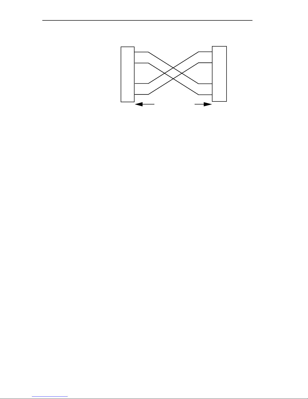
the proper pinouts (Figure 3-6) and check the cable for continuity.
8H02-16 User’s Guide 3-7
Page 32
Chapter 3: Installation
NOTE:
RX+/RX– and TX+/TX–
must share a common
color pair.
Figure 3-6 Cable Pinouts - (RJ45) Crossover Cable
TO
SmartSwitch RJ45 Port
RX+
RX– 2
TX+
TX–
1
3
6
10BASE-T Device Port
RJ45 to RJ45
TO
1
2
3
6
TX+
TX–
1574-30
c. Check that the twisted pair connection meets the dB loss and cable
specifications outlined in Chapter 2.
If a link is not established, contact Cabletron Systems Technical
Support. Refer to Section 1.7, Getting Help, for details.
RX+
RX–
4. Repeat step 2, above, until all connections have been made.
3.5.2 Connecting a UTP Segment to the FE-100TX
An FE-100-TX installed in port slot 15 and/or 16 is often used to provide
a connection between the 8H02-16 and a bridge, router, or switch.
Usually, in this configuration, a “straight-through” cable is used and the
Fast Ethernet Interface Module crossover switch shown in Figure 3-7 is
set to “not crossed over.”
Normally, when connecting devices to like devices, crossing over of the
transmit and receive pairs must occur. Before connecting a segment to the
FE-100TX, check each end of the segment to determine if the wires have
been crossed over for the proper connection.
A schematic of a crossover cable is shown in Figure 3-6. If the wires do
not cross over, use the switch on the FE-100TX to internally cross over
the RJ45 port. Figure 3-7 shows how to properly set the FE-100TX
crossover switch.
3-8 8H02-16 User’s Guide
Page 33

Connecting to the Network
Position =
(not crossed over)
1. TX+
2. TX-
3. RX+
4. NC
5. NC
6. RX-
7. NC
8. NC
Figure 3-7 FE-100TX Crossover Switch
=
FE-100TX
x
10
100
Position X
(crossed over)
1. RX+
2. RX-
3. TX+
4. NC
5. NC
6. TX-
7. NC
8. NC
166505
Connect an FE-100TX to a twisted pair segment as follows:
1. Ensure that the device at the other end of the segment is connected to
the segment and is powered ON.
2. Connect the twisted pair segment to the module by inserting the RJ45
connector on the twisted pair segment into the RJ45 port on the
module. See Figure 3-7.
8H02-16 User’s Guide 3-9
Page 34

Chapter 3: Installation
3. Verify that a Link exists by checking that the port RX LED is on
(flashing green or yellow or on solid green). If the RX LED is off,
perform the following steps until it is on:
a. Check that the 100BASE-TX de vice at the other end of the twisted
pair segment is powered up.
b. Verify that the RJ45 connector on the twisted pair segment has the
proper pinouts.
c. Check the cable for continuity.
d. Make sure that the twisted pair connection meets dB loss and cable
specifications outlined in Section 2.1.2.
e. Confirm that the crossover switch is in the correct position.
If a Link is not established, contact Cabletron Systems Technical Support.
Refer to Section 1.7, Getting Help, for details.
3.5.3 Connecting a Multimode Segment to the
FE-100FX
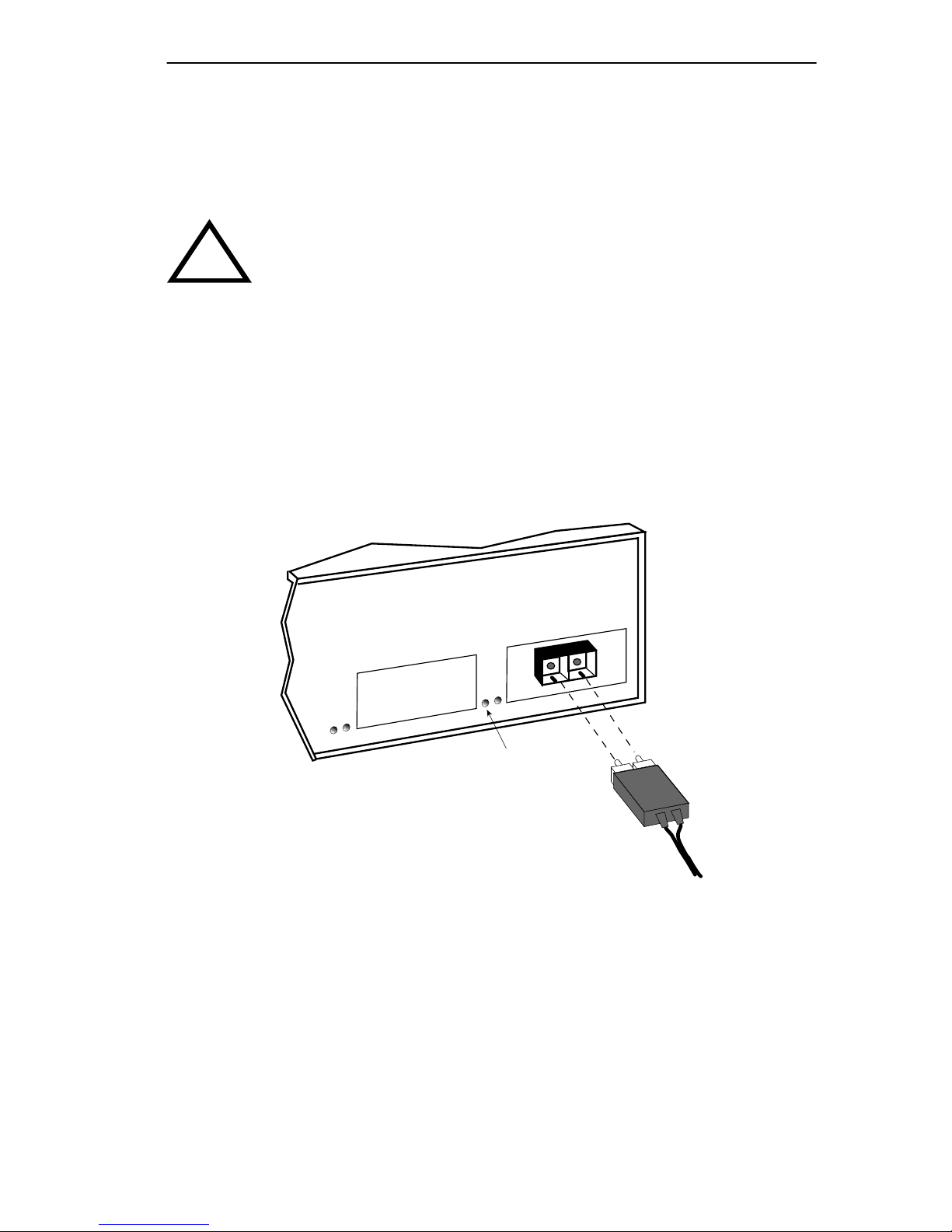
The FE-100FX has an SC style network port (see Figure 3-8). Cabletron
Systems supplies fiber optic cable that uses SC style connectors that are
keyed to ensure proper crossing over of the transmit and receive fibers.
An odd number of crossovers (preferably one) must be
!
CAUTION
maintained between devices so that the transmit port of one
device is connected to the receive port of the other device and
vice versa.
If the fiber optic cable being used has SC style connectors that
do not resemble MIC style connectors, or has SC connectors
on one end and a different type on the other, such as ST
connectors, ensure that the proper crossing over occurs.
3-10 8H02-16 User’s Guide
Page 35
Connecting to the Network
Fiber Optic Network Connection
1. Remove the protective plastic covers from the fiber optic ports on the
applicable port on the module and from the ends of the connectors.
Do not touch the ends of the fiber optic strands, and do not let
!
CAUTION
the ends come in contact with dust, dirt, or other contaminants.
Contamination of the ends causes problems in data
transmissions. If the ends become contaminated, clean them
with alcohol using a soft, clean, lint free cloth.
2. Insert one end of the SC connector into the FE-100FX installed in the
8H02-16. See Figure 3-8.
3. At the other end of the fiber optic cable, attach the SC connector to the
other device.
174234
FX
00
FE-1
16
15
RX LED
Figure 3-8 FE-100FX Port
8H02-16 User’s Guide 3-11
Page 36

Chapter 3: Installation
4. Verify that a Link exists by checking that the port RX LED is flashing
green or yellow, or on solid green. If the RX LED is off, perform the
following steps until it is on:
The port RX LED flashes green and yellow during bootup.
NOTE
a. Check that the power is turned on for the de vice at the other end of
the Link.
b. Verify proper crossing over of fiber strands between the
applicable port on the 8H02-16 and the fiber optic device at the
other end of the fiber optic link segment.
c. Verify that the fiber connection meets the dB loss specifications
outlined in Chapter 2.
If a Link has not been established, contact Cabletron Systems Technical
Support. Refer to Section 1.7, Getting Help, for details.
The 8H02-16 is now ready to be set up through Local Management. Refer
to Chapter 6, Local Management, to configure the 8H02-16.
3-12 8H02-16 User’s Guide
Page 37
CHAPTER 4
TROUBLESHOOTING
This chapter provides information concerning the following:
• Using the LANVIEW diagnostic and status monitoring system
• Troubleshooting network and 8H02-16 operational problems
• Using the RESET button
4.1 USING LANVIEW
The 8H02-16 uses Cabletron Systems built-in visual diagnostic and status
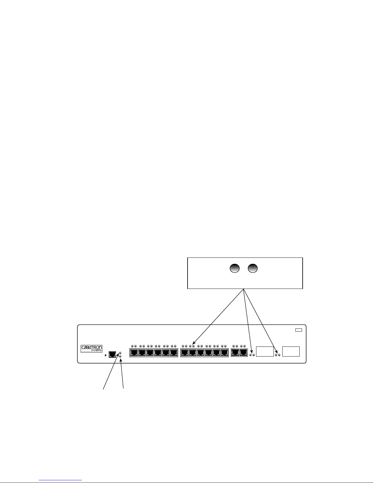
monitoring system called LANVIEW. The LANVIEW LEDs (Figure 4-1)
allow quick observation of the network status to aid in diagnosing of
network problems. Refer to Table 4-1 for a description of the LEDs.
For a functional description of the LANVIEW LED on the optional Fast
Ethernet Interface Module (FE-100TX), refer to Section 4.2.
Receive (RX) Transmit (TX)
SmartSwitch 10/100
WITH S
ECURE
F
AST VIRTUAL NETWORKING
PWR
8H02-16
RESET
PWR
COM
CPU
CPU
1X 2X 3X 4X 5X 6X 7X 8X 9X 10X 11X 12X 13X 14X 15 16
MMAC
Smart
SWITCH
174236
8H02-16 User’s Guide 4-1
Figure 4-1 LANVIEW LEDs
Page 38

Chapter 4: Troubleshooting
Table 4-1 LANVIEW LEDs
LED Color State Recommended Action
PWR Green Functional. No action.
Red 5-Volt output out of
regulation.
Contact Cabletron Systems
Technical Support.
CPU Off Power off. Power up device.
Red Flashing. Hardware
failure has occurred.
Solid. Reset, normal
Contact Cabletron Systems
Technical Support.
No action.
power up reset.
Yellow Crippled. Limited
functionality.
Contact Cabletron Systems
Technical Support.
Green Functional. No action.
Yellow
and
Green
TX Off Port enabled, and no
Booting. Blinks yellow
and green while
booting.
activity.
No action.
Should flash green every 2
seconds indicating BPDUs
being sent if STA is enabled
and there is a valid link.
Green Flashing. Indicates
No action.
activity. Rate indicates
data rate.
Yellow Blinking. Port in
standby.
Red Flashing. Indicates
collision rate.
Solid indicates
numerous collisions
and indicates a
problem.
RX Off Port in standby if
yellow TX LED is
blinking, or no Link.
Green Solid. Port enabled,
link, no activity.
Blinking. Port
disabled, link.
Yellow Flashing. Indicates
receive activity.
Port may be disabled due to
Spanning Tree.
No action.
Contact Cabletron Systems
Technical Support for
assistance.
No error.
No error.
No error.
No error.
4-2 8H02-16 User’s Guide
Page 39
FE-100TX LED
4.2 FE-100TX LED
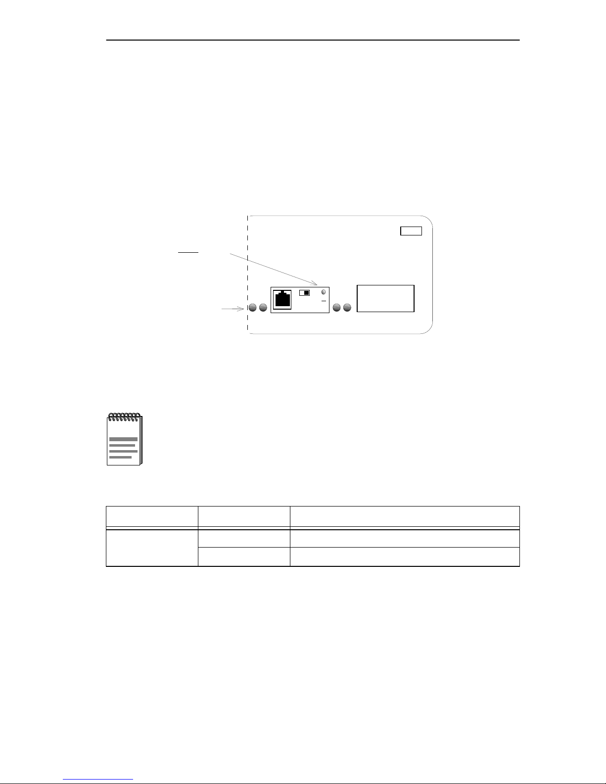
The optional FE-100TX has one LED labeled 10/100. The 10/100 LED
together with the receive LED allo ws the user to determine the Link status
and the operating speed of the Fast Ethernet Interface Module. The
10/100TX LED and the Receive (RX) LED are shown in Figure 4-2.
Table 4-2 and Table 4-3 provide a functional description of the FE-100TX
LED.
MMAC
10
LED
100
Receive (RX) LED
=
x
10
100
FE-100TX
15 16
Smart
SWITCH
174253
Figure 4-2 FE-100TX LED
A Link exists if the Receive (RX) LED is on.
NOTE
Table 4-2 FE-100TX LED (With Link)
LED Color Description
10/100 Off FE-100TX is operating at 10 Mbps.
Green FE-100TX is operating at 100 Mbps.
8H02-16 User’s Guide 4-3
Page 40
Chapter 4: Troubleshooting
No Link exists if the Receive (RX) LED is off.
NOTE
Table 4-3 FE-100TX LED (Without Link)
LED Color Description
10/100 Off No Link or no cable attached. FE-100TX
forced to 10 Mbps operation, or is
manually set to “auto-negotiate” mode.
Green No Link or no cable attached. FE-100TX is
forced to 100 Mbps operation.
4-4 8H02-16 User’s Guide
Page 41

Troubleshooting Checklist
4.3 TROUBLESHOOTING CHECKLIST
If the 8H02-16 is not working properly, refer to Table 4-4 for a checklist
of possible problems, causes, and recommended actions to resolve the
problem.
Table 4-4 Troubleshooting Checklist
Problem Possible Cause Recommended Action
All LEDs are OFF. Loss of Power to the
8H02-16.
8H02-16 not properly
installed.
No Local
Management
Password screen.
Cannot contact the
8H02-16 from
in-band
management.
Autobaud not enabled. Press ENTER (RETURN)
Terminal setup is not
correct.
Improper console cable
pinouts.
Improper Community
Names Table.
8H02-16 does not have
an IP address.
Port is disabled. Enable port.
Check the proper connection
of the power cable and its
access to a live outlet.
Check the installation.
(may take up to four times).
Refer to Chapter 5 for proper
setup procedures.
Refer to Appendix A for
proper console port pinouts.
Refer to Chapter 6
for Community Names Table
setup.
Refer to Chapter 6 for IP
address assignment
procedure.
No link to device. Check link to device.
Port(s) goes into
standby for no
apparent reason.
User parameters
(IP address, Device
and Module name,
etc.) are lost when
the 8H02-16 is
powered down or
the front panel
RESET button is
pressed.
8H02-16 detects a
looped condition.
Position of the NVRAM
RESET switch was
changed before the last
power down or pressing
of the RESET button,
causing the user-entered
parameters to reset to
factory default settings.
Discuss these configurations
with Cabletron Systems
Technical Support before
implementing them into your
network.
Reenter the lost parameters
as necessary. Call Cabletron
Systems Technical Support if
problem continues.
8H02-16 User’s Guide 4-5
Page 42
Chapter 4: Troubleshooting
4.4 USING THE RESET BUTTON
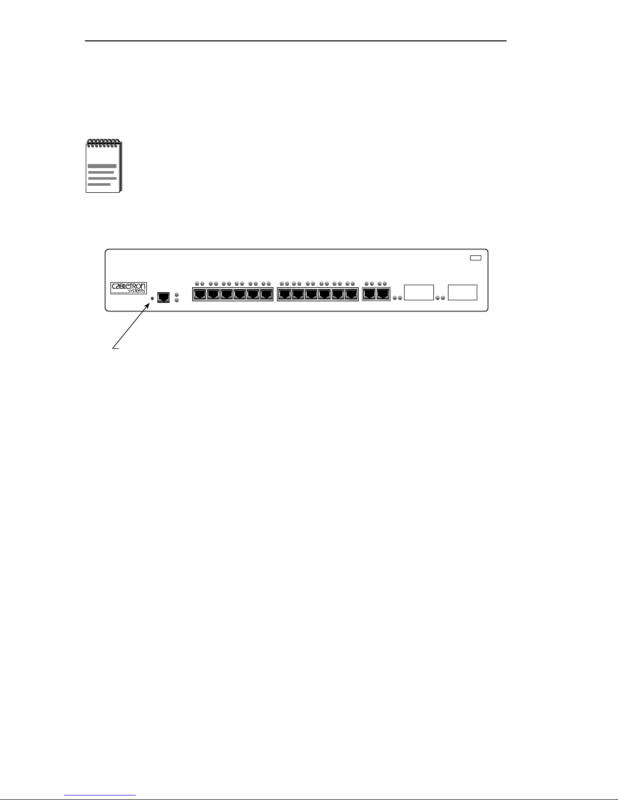
The RESET button shown in Figure 4-3 resets the 8H02-16 processor
without affecting the NVRAM.
The RESET button may be used in conjunction with mode
NOTE
switch 7, described in Appendix C, to clear user-entered
parameters such as IP addresses and Community Names and
to replace them with the 8H02-16 default settings.
SmartSwitch 10/100
WITH
S
ECURE
F
AST VIRTUAL NETWORKING
MMAC
Smart
SWITCH
PWR
COM
CPU
1X 2X 3X 4X 5X 6X 7X 8X 9X 10X 11X 12X 13X 14X 15 16
174237
8H02-16
RESET
RESET Button
Figure 4-3 RESET Button
To reset the 8H06-16 processor, use a pen or pencil to press and release
the RESET button. The 8H02-16 goes through a reset process for
approximately 45 seconds.
4-6 8H02-16 User’s Guide
Page 43

CHAPTER 5
COM PORT AND TELNET CONNECTIONS
This chapter provides information about the following items:
• Connecting and configuring a management terminal to the COM port
of the 8H02-16 to access Local Management
• Connecting an Uninterruptible Power Supply (UPS) to the COM port
of the 8H02-16 for UPS applications
• Establishing a Telnet connection
5.1 LOCAL MANAGEMENT TERMINAL CONNECTION
Connecting a terminal to access Local Management involves the
following:
• Configuring the terminal so it can communicate with the 8H02-16
• Connecting the terminal to the COM port of the 8H02-16 with an RJ45
console cable
5.2 CONFIGURING THE TERMINAL
The following instructions outline how to configure your terminal to
communicate with Local Management. Refer to your specific terminal
manual for more instructions if necessary.
Use one of the following systems to access Local Management:
• A Digital Equipment Corporation VT100 terminal
• An IBM or compatible PC running a VT100 emulation program
T o access the Setup Directory on a VT series terminal, press F3. Table 5-1
lists the required terminal setup for a VT series terminal.
8H02-16 User’s Guide 5-1
Page 44

Chapter 5: COM Port and Telnet Connections
Table 5-1 VT Terminal Setup
Display Setup Menu
Columns ->
Controls ->
Auto Wrap ->
Scroll ->
Text Cursor ->
Cursor Style ->
General Setup Menu
Mode ->
ID number ->
Cursor Keys ->
Power Supply ->
Communications Setup Menu
Transmit ->
Receive ->
XOFF ->
Bits ->
Parity ->
Stop Bit ->
Local Echo ->
Port ->
Transmit ->
Auto Answerback ->
80 Columns
Interpret Controls
No Auto Wrap
Jump Scroll
Cursor
Underline Cursor Style
VT100, 7 Bit Controls
VT100ID
Normal Cursor Keys
UPSS DEC Supplemental
2400, 4800, 9600, 19200
Receive=Transmit
XOFF at 64
8 bits
No Parity
1 Stop Bit
No Local Echo
DEC-423, Data Leads Only
Limited Transmit
No Auto Answerback
Keyboard Setup Menu
Keys ->
Auto Repeat ->
Keyclick ->
Margin Bell ->
Warning Bell ->
Typewriter Keys
any option
any option
Margin Bell
Warning Bell
5-2 8H02-16 User’s Guide
Page 45

Connecting a Management Terminal to the 8H02-16
5.3 CONNECTING A MANAGEMENT TERMINAL TO
THE 8H02-16
The 8H02-16 comes with a Console Cable Kit that provides a cable and
RJ45-to-DB9 adapter . The adapter allo ws the 8H02-16 RJ45 COM port to
connect to an IBM or compatible PC running a VT series emulation
software package. For detailed instructions regarding the connection of
the console cable to the 8H02-16, refer to the instruction sheet provided in
the Console Cable Kit.
Optional adapters are available to connect the 8H02-16 to Local
Management through a VT type terminal or a modem. Refer to the RJ45
Console Cable Kit Instruction Sheet for installation instructions and
adapter specifications.
5.4 CONNECTING THE UPS TO THE 8H02-16
The following hardware is needed to connect the 8H02-16 to the UPS:
• An RJ45 console cable
• An RJ45 to DB9 adapter
To connect a cable from the UPS to the 8H02-16 COM port, perform the
following steps:
1. Plug the RJ45 console cable into the 8H02-16 COM port.
2. Plug the other end of the console cable into the adapter and connect the
adapter to the UPS.
With the cable connection complete and with a valid IP address entered
into the 8H02-16 through Local Management (see Chapter 6) or through
Runtime IP Address Discovery (refer to Section 5.5, Runtime IP
Address Discovery), use one of the following management tools to
configure the 8H02-16 COM port for the UPS application:
• 8H02-16 Local Management through Telnet. The General
Configuration screen described in Chapter 6, Section 6.6.12, provides
the instructions to set up the COM port for the UPS application.
• Graphical user interfaces (GUIs) provided by SPECTRUM Element
Manager for Windows, SPECTRUM Portable Management
Applications (SPMAs), or SPECTRUM software packages.
8H02-16 User’s Guide 5-3
Page 46

Chapter 5: COM Port and Telnet Connections
5.5 RUNTIME IP ADDRESS DISCOVERY
Upon power up, the 8H02-16, through a function called Runtime IP
Address Discovery, sends out a RARP and BootP request over the
network to determine its IP address. This function allows the loading of
an IP address into NVRAM on the 8H02-16 without using Local
Management. For information on setting up a workstation to act as a
server to respond to a RARP or BootP request, refer to the specific
workstation documentation.
5.6 COM PORT AND TELNET CONNECTIONS
Once the 8H02-16 has a valid IP address, establish a Telnet session with
Local Management from any TCP/IP based node on the network. Telnet
connections to the 8H02-16 require the community name passwords
assigned at the SNMP Community Names screen. Refer to Section 6.7,
SNMP Community Names Screen, of this manual for additional
information about community names.
NOTE
Refer to the instructions included with the Telnet application for
information about establishing a Telnet session.
5-4 8H02-16 User’s Guide
Page 47

CHAPTER 6
LOCAL MANAGEMENT
This chapter describes how to access and use Local Management for the
8H02-16.
6.1 OVERVIEW
Local Management for the 8H02-16 consists of a series of management
screens that allow the management of the 8H02-16 and its attached
segments. The management screens allow the user to do the following
tasks:
• Assign IP addresses and subnet masks to the 8H02-16
• Select a default gateway and subnet mask
• Control access to the 8H02-16 by establishing community names
• Clear NVRAM
• Force a FLASH Download
• Designate which Network Management Workstations receive SNMP
traps from the device
There are four ways to access Local Management:
• Locally using a VT type terminal connected to the COM port of the
8H02-16.
• Remotely using a VT type terminal connected through a modem.
• In-band through a Telnet connection.
• Out-of-band through a Telnet connection to the COM port of the
8H02-16 when the port is configured for SLIP or PPP.
Chapter 5 contains details on how to connect a terminal to the 8H02-16
COM port to access Local Management.
8H02-16 User’s Guide 6-1
Page 48

Chapter 6: Local Management
6.2 LOCAL MANAGEMENT KEYBOARD
CONVENTIONS
All key names appear as capital letters in this manual. Table 6-1 explains
the keyboard conventions and the key functions that are used.
Table 6-1 Keyboard Conventions
Key Function
These are selection keys that perform the same
ENTER Key
RETURN Key
ESCAPE (ESC) Key
Local Management function. For example, “Press
ENTER” means that you can press either ENTER
or RETURN, unless this manual specifically
instructs you otherwise.
This key allows an escape from a Local
Management screen without saving changes. For
example, “Press ESC twice” means the ESC key
must be pressed quickly two times.
SPACE bar
BACKSPACE Key
Arrow Keys
[–] Key
DEL Key
These keys cycle through selections in some Local
Management fields. Use the SPACE bar to cycle
forward through selections and use BACKSPACE
to cycle backward through selections.
These are navigation keys. Use the UP-ARROW,
DOWN-ARROW, LEFT-ARROW, and
RIGHT-ARROW keys to move the screen cursor.
For e xample , “Use the arrow keys” means to press
whichever arrow key moves the cursor to the
desired field on the Local Management screen.
This key decreases values from a Local
Management increment field. For example, “Press
[–]” means to press the minus sign key.
The DEL (Delete) key removes characters from a
Local Management field. For example, “Press
DEL” means to press the Delete key.
6-2 8H02-16 User’s Guide
Page 49

Accessing Local Management
6.3 ACCESSING LOCAL MANAGEMENT
Perform the following steps to access Local Management:
1. Turn on the terminal. Press ENTER (up to four times) until the
8H02-16 Local Management Password screen, Figure 6-1, appears.
Event Message Line
8H02-16 LOCAL MANAGEMENT
CABLETRON Systems, Incorporated
P.O.Box 5005
Rochester, NH 03866-5005 USA
(603) 332-9400
(c) Copyright CABLETRON Systems, Inc, 1996
Device Serial Number:
Device Hardware Revision:
Device Firmware Revision:
Device BOOTPROM Revision:
Enter Password:
XX.XX.XX
XX
XX.XX.XX
XX.XX.XX
Figure 6-1 The 8H02-16 Local Management Password Screen
174212
8H02-16 User’s Guide 6-3
Page 50
Chapter 6: Local Management
2. Enter the Password and press ENTER. The default Super-User access
password is “public” or press ENTER.
The user’s password is one of the community names specified
NOTE
in the SNMP Community Names screen. Access to certain
Local Management capabilities depends on the degree of
access accorded that community name. Refer to Section 6.7.
• If an invalid password is entered, the terminal beeps and the cursor
returns to the beginning of the password entry field.
• Entering a valid password causes the associated access le vel to display
at the bottom of the screen and the Device Menu screen to appear.
• If no activity occurs for several minutes, the Password screen
reappears and the password has to be reentered.
6.3.1 Navigating Local Management Screens
The 8H02-16 Local Management consists of a series of menu screens.
Figure 6-2 shows the hierarchy of the 8H02-16 Local Management
screens.
\
Password
Device
Menu
Device
Configuration
Menu
Device
Statistics
Menu
General Configuration
SNMPCommunity Names
SNMP Traps
Bridge Configuration
Device Specific
Configuration Menu
Bridge Statistics
Port Statistics
Full Duplex
Configuration
System
Resources
High Speed
Interface
Configuration
Flash Download
Clear NVRAM
Port Redirect
Function
Network Tools
Figure 6-2 Hierarchy of Local Management Screens
6-4 8H02-16 User’s Guide
174243
Page 51

Accessing Local Management
6.3.2 Selecting Local Management Menu Screen Items
Select items on a menu screen by performing the following steps:
1. Use the arrow keys to highlight a menu item.
2. Press ENTER. The selected menu item appears on the screen.
6.3.3 Exiting Local Management Screens
Exit a Local Management screen by performing the following steps:
1. Use the arrow keys to highlight the RETURN command at the bottom
of the Local Management screen.
2. Press ENTER. The previous screen in the Local Management
hierarchy appears.
The user can also exit Local Management screens by pressing
NOTE
ESC twice. This exit method does not warn about unsaved
changes and all unsaved changes will be lost.
3. Exit from 8H02-16 Local Management by repeating steps 1 and 2 until
the Device Menu screen appears.
4. Use the arrow keys to highlight the RETURN command at the bottom
of the Device Menu screen.
5. Press ENTER. The Password screen appears and the session ends.
8H02-16 User’s Guide 6-5
Page 52

Chapter 6: Local Management
6.4 DEVICE MENU SCREEN
The Device Menu screen is the access point for all Local Management
screens. Figure 6-3 shows the Device Menu screen.
Event Message Line
8H02-16 LOCAL MANAGEMENT
Device Menu
Device Name: 8H02-16
DEVICE CONFIGURATION
DEVICE STATISTICS
NETWORK TOOLS
Firmware Revision: XX.XX.XX
BOOTPROM Revision: XX.XX.XX
Figure 6-3 Device Menu Screen
RETURN
174213
6-6 8H02-16 User’s Guide
Page 53

Device Menu Screen
The following explains each Device Menu screen field as shown in
Figure 6-3:
DEVICE CONFIGURATION
The Device Configuration screen provides access to the Local
Management screens that are used to configure the 8H02-16 and also to
the Device Specific Configuration Menu screen. The Device Specific
Configuration Menu screen provides access to the screens that allow the
user to check the 8H02-16 resources and set operating parameters specific
to each port. For details about the Device Configuration Menu screen,
refer to Section 6.5. For details about the Device Specific Configuration
Menu screen, refer to Section 6.11.
DEVICE STATISTICS
The Device Statistics screen provides statistics and performance
information for the 8H02-16. For details about this screen, refer to
Section 6.18.
NETWORK T OOLS
The Network Tools function resides on the 8H02-16 and consists of a
series of commands that allow the user to access and manage network
devices. Section 6.21 explains how to use the Network Tools utility.
If the terminal is idle for several minutes, the Password screen reappears
and the password has to be reentered.
8H02-16 User’s Guide 6-7
Page 54

Chapter 6: Local Management
6.5 DEVICE CONFIGURATION MENU SCREEN
The Device Configuration Menu screen, Figure 6-4, provides access to
Local Management screens that allow the user to configure and monitor
operating parameters, modify SNMP community names, set SNMP traps,
configure bridge parameters and configure 8H02-16 ports.
Event Message Line
8H02-16 LOCAL MANAGEMENT
Device Configuration Menu
Device Name: 8H02-16
GENERAL CONFIGURATION
SNMP COMMUNITY NAMES
SNMP TRAPS
BRIDGE CONFIGURATION
DEVICE SPECIFIC CONFIGURATION
Firmware Revision: XX.XX.XX
BOOTPROM Revision: XX.XX.XX
Figure 6-4 Device Configuration Menu Screen
RETURN
174242
6-8 8H02-16 User’s Guide
Page 55

Device Configuration Menu Screen
The following explains each Device Configuration menu screen as shown
in Figure 6-4:
GENERAL CONFIGURATION
The General Configuration screen allows the user to monitor and
configure operating parameters for the 8H02-16. For details, refer
to Section 6.6.
SNMP COMMUNITY NAMES
The SNMP Community Names screen allows the user to change or re view
the community names used as access passwords for local management
operation. For details, refer to Section 6.7.
SNMP TRAPS
The SNMP Traps screen provides display and configuration access to the
table of IP addresses used for trap destinations and associated community
names. For details, refer to Section 6.8.
BRIDGE CONFIGURATION
The Bridge Configuration screen provides basic setup options for making
a bridge operational in the network. For details, refer to Section 6.10.
DEVICE SPECIFIC CONFIGURATION
The Device Specific Configuration screen allo ws the user to select one of
four screens to configure ports or check system resources specific to the
8H02-16. For details, refer to Section 6.11.
8H02-16 User’s Guide 6-9
Page 56

Chapter 6: Local Management
6.6 GENERAL CONFIGURATION SCREEN
The General Configuration screen, Figure 6-5, allows the user to set the
system date and time, IP addresses and Subnet Masks, the Default
Interface and Default Gateway, the TFTP Gateway IP address, and the
COM port configuration.
Access the General Configuration screen from the Device Configuration
Menu screen by using the arrow keys to highlight the General
Configuration option and pressing ENTER. The General Configuration
screen, Figure 6-5, appears.
Event Message Line
8H02-16 LOCAL MANAGEMENT
General Configuration
Device Name: 8H02-16
Firmware Revision: XX.XX.XX
BOOTPROM Revision: XX.XX.XX
MAC Address:
IP Address:
Subnet Mask:
Default Gateway:
Default Interface:
TFTP Gateway IP Addr:
Com 1: [ENABLED] Application: [LM]
00-00-ID-00-00-00
0.0.0.0
0.0.0.0
NONE DEFINED
NONE DEFINED
0.0.0.0
Device Date:
Device Time:
Screen Refresh Time:
Screen Lockout Time:
10/11/93
14:23:00
30 sec.
15 min.
RETURNSAVE
174215
Figure 6-5 General Configuration Screen
The following briefly explains each General Configuration screen field:
MAC Address (Read-Only)
Displays the physical address of the 8H02-16.
IP Address (Modifiable)
The display allows the IP address to be set for the 8H02-16.
6-10 8H02-16 User’s Guide
Page 57

General Configuration Screen
Subnet Mask (Modifiable)
Displays the subnet mask for the 8H02-16. A subnet mask “masks out”
the network bits of the IP address by setting the bits in the mask to 1 when
the network treats the corresponding bits in the IP address as part of the
network or subnetwork address, or to 0 if the corresponding bit identifies
the host. For details about how to change the Subnet Mask from its def ault
value, refer to Section 6.6.2.
Default Gateway (Modifiable)
Displays the default gateway for the 8H02-16. This field is not defined
until an appropriate value is entered. For details about why and ho w to set
the Default Gateway, refer to Section 6.6.3.
Default Interface (Modifiable)
Displays the default interface for the 8H02-16 default gateway. The field
defaults to NONE. For details about when and how to set the Default
Interface, refer to Section 6.6.4.
TFTP Gateway IP Addr. (Modifiable)
Displays and allows the user to set the TFTP Gateway IP address for the
8H02-16. To set the TFTP Gateway IP address, refer to Section 6.6.5.
Device Date (Modifiable)
Contains a value that the device recognizes as the current date. To set a
new device date, refer to Section 6.6.6.
Device Time (Modifiable)
Contains a value that the de vice recognizes as the current time. To enter a
new time, refer to Section 6.6.7.
Screen Refresh Time (Modifiable)
Contains the rate at which the screens are updated. This setting
determines how frequently (in seconds) information is updated on the
screen. To enter a new update time, refer to Section 6.6.8.
8H02-16 User’s Guide 6-11
Page 58

Chapter 6: Local Management
Screen Lockout Time (Modifiable)
Contains the maximum number of minutes that the Local Management
application displays a module’s screen while awaiting input or action
from a user. For example, if the number 5 is entered in this field, the user
has up to five minutes to respond to each of the specified module’s Local
Management screens. In this example, after five minutes of “idleness” (no
input or action), the terminal “beeps” five times, the Local Management
application terminates the session, and the display returns to the Password
screen. To enter a new lockout time, refer to Section 6.6.9.
Com 1 (Modifiable)
This field allows the user to enable or disable the COM port. The
selection toggles between ENABLE and DISABLE. The default is
ENABLED. For details about setting up the COM port, refer to
Section 6.6.10.
Application (Modifiable)
Displays the application set for the COM port. This field allows the user
to set the application that the COM port supports. The field steps between
LM (Local Management), SLIP (Serial Line Interface Protocol), PPP
(Point-to-Point Protocol), or UPS (Uninterruptible Power Supply).
The UPS setting allows the COM port to be used to monitor an American
Power Conversion Smart Uninterruptible Power Supply (UPS).
The baud rate setting for LM is automatically sensed. For UPS, the baud
rate is automatically set to 2400. The baud rate must be manually set in
the Baud Rate field if either PPP or SLIP is selected.
The default setting is LM. For details about how to configure the COM
port for various applications, refer to Section 6.6.10.
Baud Rate (Modifiable)
Displays the baud rate setting of the device attached to the 8H02-16
through the COM port. The field steps between 2400, 4800, 9600 or
19,200. This selection is only available if SLIP or PPP is selected in the
Application field.
6-12 8H02-16 User’s Guide
Page 59

General Configuration Screen
6.6.1 Setting the IP Address
Set the IP address by performing the following steps:
1. Use the arrow keys to highlight the IP Address field.
2. Enter the IP address into this field using Decimal Dotted Notation
(DDN) format.
For example: 134.141.79.120
3. Press ENTER. If the IP address is a valid format, the cursor returns to
the beginning of the IP address field. If the entry is not valid, the Event
Message Line displays “INVALID IP ADDRESS OR FORMAT
ENTERED”. Local Management does not alter the current value and
refreshes the IP address field with the previous value.
4. Use the arrow keys to highlight the SAVE command, then press
ENTER. The “SAVED OK” message appears indicating that the
changes have been saved to memory.
The device automatically resets after a new IP address is
NOTE
saved.
6.6.2 Setting the Subnet Mask
If the management workstation that is to receive SNMP traps from the
8H02-16 is located on a separate subnet, the subnet mask for the 8H02-16
must be changed from its default.
To change the subnet mask from its default, perform the following steps:
1. Use the arrow keys to highlight the Subnet Mask field.
2. Enter the subnet mask into this field using Decimal Dotted Notation
(DDN) format.
For example: 255.255.0.0
8H02-16 User’s Guide 6-13
Page 60

Chapter 6: Local Management
3. Press ENTER. If the subnet mask is valid, the cursor returns to the
beginning of the Subnet Mask field. If the entry is not valid, the Event
Message Line displays “INVALID SUBNET MASK OR FORMAT
ENTERED”. Local Management does not alter the current value, but
it does refresh the Subnet Mask field with the previous value.
4. Use the arrow keys to highlight the SAVE command.
5. Press ENTER. The Event Message Line at the top of the screen
displays “SAVED OK”, and the device resets.
6.6.3 Setting the Default Gateway
If the SNMP management station is located on a different IP subnet than
the 8H02-16, a default gateway must be specified. When an SNMP Trap is
generated, the 8H02-16 sends the Trap to the default gateway. To set the
default gateway, perform the following steps:
1. Use the arrow keys to highlight the Default Gateway field.
2. Enter the IP address of the default gateway using the DDN format.
For example: 134.141.79.121
3. Press ENTER. If the default gateway entered is a valid format, the
cursor returns to the beginning of the Default Gateway field. If the
entry is not valid, the Event Message Line displays “INVALID
DEFAULT GATEWAY OR FORMAT ENTERED”. Local
Management does not alter the current value, but it does refresh the
Default Gateway field with the previous value.
4. Use the arrow keys to highlight the SAVE command.
5. Press ENTER. The Event Message Line at the top of the screen
displays “SAVED OK”.
6-14 8H02-16 User’s Guide
Page 61

General Configuration Screen
6.6.4 Setting the Default Interface
The default interface is the interface channel for the designated default
gateway. Set the default interface by performing the following steps:
1. Use the arrow keys to highlight the Default Interface field.
2. Enter the interface number for the default gateway in this field with a
value from 1 to 16.
3. Press ENTER. If the interface number entered is a valid format, the
cursor returns to the beginning of the Default Interface field. If the
entry is not valid, the Event Message Line displays “PERMISSIBLE
RANGE: 1...16”. Local Management does not alter the current value,
but it does refresh the Default Interface field with the previous value.
4. Use the arrow keys to highlight the SAVE command.
5. Press ENTER. The Event Message Line at the top of the screen
displays “SAVED OK”.
6.6.5 Setting the TFTP Gateway IP Address
If the network TFTP server is located on a different IP subnet than the
8H02-16, a gateway IP address should be specified. To set the TFTP
gateway IP address, perform the following steps:
1. Use the arrow keys to highlight the TFTP Gateway IP Address field.
2. Enter the IP address of the TFTP gateway using the DDN format.
For example: 134.141.80.122
3. Press ENTER. If the TFTP gateway IP address entered is a valid
format, the cursor returns to the beginning of the TFTP Gateway IP
Address field. If the entry is not valid, the Event Message Line
displays “INVALID TFTP GATEWAY IP ADDRESS OR FORMAT
ENTERED”. Local Management does not alter the current value, but
it does refresh the TFTP Gateway IP Address field with the previous
value.
4. Use the arrow keys to highlight the SAVE command.
5. Press ENTER. The Event Message Line at the top of the screen
displays “SAVED OK”.
8H02-16 User’s Guide 6-15
Page 62
Chapter 6: Local Management
6.6.6 Setting the Device Date
To set the system date, perform the following steps:
1. Use the arrow keys to highlight the Device Date field.
2. Enter the date in a MM/DD/YY format.
It is not necessary to add separators between month, day, and
NOTE
3. Press ENTER to set the system calender to the date in the input field.
4. Use the arrow keys to highlight the SAVE command at the bottom of
the screen and press ENTER.
year numbers, as long as each entry uses two numeric
characters. For example, to set the date to 03/17/96, type
“031796” in the Device Date field.
If the date entered is a valid format, the Event Message Line at the top of
the screen displays “SAVED OK”. If the entry is not valid, Local
Management does not alter the current value, but it does refresh the
Device Date field with the previous value.
6.6.7 Setting the Device Time
To set the device clock, perform the following steps:
1. Use the arrow keys to highlight the Device Time field.
2. Enter the time in a 24-hour format, HH:MM:SS.
When entering the time in the system time field, separators
NOTE
between hours, minutes, and seconds do not need to be added
as long as each entry uses two numeric characters. For
example, to set the time to 6:45 A.M., type “064500” in the
Device Time field.
3. Press ENTER to set the system clock to the time in the input field.
4. Use the arrow keys to highlight the SAVE command at the bottom of
the screen and press ENTER.
6-16 8H02-16 User’s Guide
Page 63

General Configuration Screen
If the time entered is a valid format, the Event Message Line at the top of
the screen displays “SAVED OK”. If the entry is not valid, Local
Management does not alter the current value and refreshes the Device
Time field with the previous value.
6.6.8 Entering a New Screen Refresh Time
The screen refresh time is set from 3 to 99 seconds with a default of 3
seconds. To set a new screen refresh rate, perform the following steps:
1. Use the arrow keys to highlight the Screen Refresh Time field.
2. Enter a number from 3 to 99.
3. Press ENTER to set the refresh rate to the time in the input field.
4. Use the arrow keys to highlight the SAVE command at the bottom of
the screen and press ENTER.
If the time entered is within the 3 to 99 seconds range, the Event Message
Line at the top of the screen displays “SAVED OK”. If the entry is not
valid, Local Management does not alter the current setting, but it does
refresh the Screen Refresh Time field with the previous value.
6.6.9 Setting the Screen Lockout Time
The screen lockout time can be set from 1 to 30 minutes with a default of
15 minutes. To set a new lockout time, perform the following steps:
1. Use the arrow keys to highlight the Screen Lockout field.
2. Enter a number from 1 to 30.
3. Press ENTER to set the lockout time in the input field.
4. Use the arrow keys to highlight the SAVE command at the bottom of
the screen and press ENTER.
If the time entered is within the 1 to 30 minutes range, the Event Message
Line at the top of the screen displays “SAVED OK”. If the entry is not
valid, Local Management does not alter the current setting, but it does
refresh the Screen Lockout Time field with the previous value.
8H02-16 User’s Guide 6-17
Page 64

Chapter 6: Local Management
6.6.10 Configuring the COM Port
Before altering the COM port settings, ensure that a valid IP
!
CAUTION
The 8H02-16 COM port supports the following applications:
NOTE
• Local Management connections
address is set for this device (Refer to Section 6.6.1, Setting
the IP Address). Read this entire COM port configuration
section before changing the settings of the COM port.
Refer to the Release Notes included with the 8H02-16 to v erify
which COM Port applications are currently supported.
• American Power Conversion (APC) Uninterruptible Power Supply
(UPS) connections
• Telnet connections using SLIP or PPP
To enable the COM port and select a supported application, refer to
Section 6.6.11 and Section 6.6.12.
6-18 8H02-16 User’s Guide
Page 65

General Configuration Screen
6.6.11 Enabling the COM Port
To enable the COM port, perform the following steps:
1. Use the arrow keys to highlight the Com 1 field.
Do NOT disable or alter the settings of the COM port while
!
CAUTION
operating the current Local Management connection through a
terminal. Altering the COM port settings disconnects the Local
Management terminal from the port, and ends the Local
Management session.
If the 8H02-16 was previously assigned a valid IP address,
reenter Local Management by establishing a Telnet connection
to the device. If the device does not have a valid IP address,
reset NVRAM on the 8H02-16 (refer to Appendix C) in order to
reestablish COM port communications.
2. Press the SPACE bar to choose either ENABLE or DISABLE.
If the COM port is reconfigured without a valid IP address set
!
CAUTION
on the device, the message shown in Figure 6-6 appears.
Do not continue unless the outcome of the action is fully
understood.
8H02-16 User’s Guide 6-19
Page 66

Chapter 6: Local Management
WARNING
THE COM PORT HAS BEEN RECONFIGURED AND THERE IS NO IP
ADDRESS SET FOR THIS DEVICE. YOU WILL NO LONGER BE ABLE
TO MANAGE THIS BOARD. DO YOU STILL WISH TO RECONFIGURE
THIS COM PORT?
YES
Figure 6-6 COM Port Warning Screen
NO
174252
3. Use the arrow keys to highlight YES. Press ENTER.
4. If you ENABLE the port, refer to Section 6.6.12. Otherwise, use the
arrow keys to highlight SAVE at the bottom of the screen, then press
ENTER.
5. When the message “SAVED OK” appears, the edits are saved.
Exiting without saving causes the message “NOT SAVED --
!
CAUTION
PRESS SAVE TO KEEP CHANGES” to appear. Exiting without
saving causes all edits to be lost.
6-20 8H02-16 User’s Guide
Page 67
General Configuration Screen
6.6.12 Changing the COM Port Application
After enabling the COM port as described in Section 6.6.11, select one of
the four applications supported by the COM port: LM, SLIP, PPP or UPS.
The default application is LM.
If the COM port is reconfigured without a valid IP address set
!
CAUTION
To change the COM port application:
1. Use the arrows keys to highlight the Application field.
2. Use the SPACE bar or BACKSPACE to step through the available
settings until the required operation appears. Table 6-2 lists the
available settings and their corresponding applications.
on the device, the message shown in Figure 6-6 appears. Do
not continue unless the outcome of the action is fully
understood.
Table 6-2 COM Port Application Settings
Setting Application
[LM] Local Management Session
[UPS] APC Power Supply SNMP Proxy
[SLIP] Serial Line Interface Protocol
[PPP] Point-to-Point Protocol
3. Press ENTER to accept the application.
4. Use the arrow keys to highlight SAVE at the bottom of the screen, then
press ENTER.
5. When the message “SAVED OK” appears, the edits are saved.
8H02-16 User’s Guide 6-21
Page 68

Chapter 6: Local Management
6.6.13 Setting the Baud Rate
If SLIP or PPP is selected in the previous section, a separate field appears
to the right of the Application field that allows the user to select the baud
rate. Change the baud rate setting as follows:
1. Use the arrow keys to highlight the Baud Rate field.
2. Use the SPACE bar or BACKSPACE to step to the correct setting.
3. Press ENTER to accept the baud rate.
4. Use the arrow keys to highlight SAVE at the bottom of the screen, then
press ENTER.
5. When the message “SAVED OK” appears, the edits are saved.
6-22 8H02-16 User’s Guide
Page 69

SNMP Community Names Screen
6.7 SNMP COMMUNITY NAMES SCREEN
The SNMP Community Names option allows the user to set Local
Management community names. Community names act as passwords to
Local/Remote Management and are agents of security access to the
8H02-16. Access to the 8H02-16 is controlled by enacting any of three
different levels of security authorization (read-only, read-write, and
super-user).
Super-User access gives the user full management privileges,
NOTE
Access the SNMP Community Names screen from the Device
Configuration Menu screen by using the arrow keys to highlight the
SNMP Community Names option and pressing ENTER. The SNMP
Community Names screen, Figure 6-7, appears.
allows existing passwords to be changed, and all modifiable
MIB objects for the Cabletron Container MIB and Internet
MIB-II to be edited.
Event Message Line
Device Name: 8H02-16
8H02-16 LOCAL MANAGEMENT
SNMP Community Names
Community Name
public
public
public
Firmware Revision: XX.XX.XX
BOOTPROM Revision: XX.XX.XX
Access Policy
read-only
read-write
super-user
RETURNSAVE
174216
Figure 6-7 The SNMP Community Names Screen
8H02-16 User’s Guide 6-23
Page 70

Chapter 6: Local Management
The following explains each SNMP Community Names screen field:
Community Name (Modifiable)
Displays the user-defined name through which a user accesses the
8H02-16 Local Management. Any community name assigned here acts as
a password to Local Management.
Access Policy (Read-Only)
Indicates the access status accorded each community name. Possible
selections are as follows:
Read-Only (RO) This community name gives the user extended
read-only access to 8H02-16 MIB objects, and
excludes access to security-protected fields of
read-write or super-user authorization.
Read-Write (RW) This community name gives the user read and
write access to the 8H02-16 MIB objects,
excluding security protected fields for
super-user access only.
Super-User (SU) This community name gives the user read-write
access to the 8H02-16
MIB objects and allows
the user to change all modifiable parameters
including community names, IP addresses,
traps, and SNMP objects.
6-24 8H02-16 User’s Guide
Page 71
SNMP Community Names Screen
6.7.1 Establishing Community Names
The password used to access Local Management at the Password Screen
must have Super-User access in order for edits in the SNMP Community
Names screen to take effect. Using a password with Read-Only or
Read-Write access does not allow the user to edit the SNMP Community
Names screen.
Any community name assigned in the SNMP Community
NOTE
To establish community names, proceed as follows:
1. Use the arrow keys to highlight the Community Name field adjacent
to the selected access level.
Names screen is a password to its corresponding level of
access to Local Management. The community name assigned
Super-User access is the only one that gives the user complete
access to Local Management.
2. Enter the password in the field (maximum 31 characters).
3. Press ENTER.
4. Repeat steps 1 through 3 to modify the other community names.
5. Use the arrow keys to highlight SAVE at the bottom of the screen and
press ENTER. The message “SAVED OK” appears. The community
names are saved to memory and their access modes implemented.
Exiting without saving causes a “NOT SAVED?” message to
NOTE
display above the SAVE command. Edits will be lost if they are
not saved before exiting.
6. To exit the screen, use the arrow keys to highlight RETURN and press
ENTER.
8H02-16 User’s Guide 6-25
Page 72

Chapter 6: Local Management
6.8 SNMP TRAPS SCREEN
Since the 8H02-16 is an SNMP compliant device, it sends messages to
multiple Network Management Stations to alert users of status changes.
The SNMP Traps screen is shown in Figure 6-8.
Access the SNMP Traps screen from the Device Configuration Menu
screen by using the arrow keys to highlight the SNMP Traps option and
pressing ENTER. The SNMP Traps screen shown in Figure 6-8 appears.
Event Message Line
8H02-16 LOCAL MANAGEMENT
SNMP Traps
Device Name: 8H02-16
Firmware Revision: XX.XX.XX
BOOTPROM Revision: XX.XX.XX
Trap Destination
0.0.0.0
0.0.0.0
0.0.0.0
0.0.0.0
0.0.0.0
0.0.0.0
0.0.0.0
0.0.0.0
Trap Community Name
public
public
public
public
public
public
public
public
Enable Traps
[NO]
[NO]
[NO]
[NO]
[NO]
[NO]
[NO]
[NO]
RETURNSAVE
174217
Figure 6-8 The SNMP Traps Screen
The following explains each field of the SNMP Traps screen.
Trap Destination (Modifiable)
Indicates the IP address of the workstation to receive trap alarms up to
eight destinations.
Trap Community Name (Modifiable)
Displays the Community Name included in the trap message sent to the
Network Management Station with the associated IP address.
6-26 8H02-16 User’s Guide
Page 73

Configuring the Trap T able
Enable Traps (Toggle)
Enables transmission of the traps to the network management station with
the associated IP address. This field toggles between [YES] and [NO].
6.9 CONFIGURING THE TRAP TABLE
To configure the Trap table, proceed as follows:
1. Using the arrow keys, highlight the appropriate Trap Destination field.
2. Enter the IP Address of the workstation that is to receive traps. IP
address entries must follow the DDN format.
For example: 134.141.79.121
3. Press ENTER. If an invalid entry is entered “INVALID IP
ENTERED” is displayed in the Event Message Line.
4. Using the arrow keys, highlight the Trap Community Name field.
Enter the community name.
5. Press ENTER.
6. Using the arrow keys, highlight the Enable Traps field. Press the
SPACE bar to choose either [YES] (send alarms from the 8H02-16 to
the workstation), or [NO] (prevent alarms from being sent).
7. Using the arrow keys, highlight the SAVE option and press ENTER.
The message “SAVED OK” appears on the screen.
Exiting without saving causes a “NOT SAVED?” message to
NOTE
appear above the SAVE command. Edits will be lost if they are
not saved before exiting.
8. To exit the screen, use the arrow keys to highlight RETURN and press
ENTER.
The designated workstations now receive traps from the 8H02-16.
8H02-16 User’s Guide 6-27
Page 74

Chapter 6: Local Management
6.10 BRIDGE CONFIGURATION SCREEN
The Bridge Configuration screen, Figure 6-9, provides the basic setup
options to make a bridge operational in your network.
Access the Bridge Configuration screen from the Device Configuration
menu by using the arrow keys to highlight the Bridge Configuration
option and pressing ENTER. The Bridge Configuration screen,
Figure 6-9, appears.
Event Message Line
8H02-16 LOCAL MANAGEMENT
Bridge Configuration
Device Name: 8H02-16
Firmware Revision: XX.XX.XX
BOOTPROM Revision: XX.XX.XX
Bridge Address: 00-00-1D-00-00-00
Number of Ports: 16
Port #
1
2
3
4
5
6
7
8
MAC Address
00-00-1D-00-00-00
00-00-1D-00-00-01
00-00-1D-00-00-02
00-00-1D-00-00-03
00-00-1D-00-00-04
00-00-1D-00-00-05
00-00-1D-00-00-06
00-00-1D-00-00-07
Type of STA: [DEC]
State
learning
listening
standby
learning
listening
standby
listening
listening
[9-16]
Status
[ENABLED]
[DISABLED]
[ENABLED]
[DISABLED]
[ENABLED]
[DISABLED]
[ENABLED]
[DISABLED]
RETURNSAVE
Figure 6-9 Bridge Configuration Screen
The following describe each field of the Bridge Configuration screen:
Bridge Address (Read-Only)
Displays the MAC address of the bridge.
174218
Number of Ports (Read-Only)
Displays the total number of bridged ports on the 8H02-16.
6-28 8H02-16 User’s Guide
Page 75

Bridge Configuration Screen
Type of STA (Toggle)
Allows the user to set the method that bridges use to decide which bridge
is the controlling (Root) bridge when two or more bridges exist in parallel
(Spanning Tree Algorithm). Valid entries include IEEE, DEC, and None.
To set the STA, refer to Section 6.10.1.
Port # (Read-Only)
Lists each bridge port on the device. If the number of ports is greater than
eight, then the additional ports are listed on subsequent screens.
MAC Address (Read-Only)
Displays the hardware address assigned to each listed port.
State (Read-Only)
Disabled: Management disabled this interface. No traffic is received or
forwarded while the interface is disabled.
Learning: The bridge is learning the network address of this interface. The
bridge enters the learning state when the Transparent Database is created
(during start-up or after being deleted), or when the Spanning Tree
Algorithm detects a network topology change.
Listening: The bridge is not adding information to the Transparent
Database. The bridge is monitoring BPDU traffic while preparing to mo ve
from the learning to the forwarding state.
Forwarding: The bridge is on line and this interface is forwarding traffic.
Blocking: This interface will not forward any traffic through the bridge.
Status (Toggle)
Allows the user to disable or enable a port by setting the status of the
listed interface to either ENABLED or DISABLED. To set the port status,
refer to Section 6.10.2.
8H02-16 User’s Guide 6-29
Page 76

Chapter 6: Local Management
6.10.1 Selecting the STA
The STA setting allows the user to set the method that the bridges use to
decide which is the controller (Root) bridge when two or more bridges are
in parallel (Spanning T ree Algorithm). The available selections are IEEE,
DEC, and NONE.
To set the STA, proceed as follows:
1. Use the arrow keys to highlight the Type of STA field.
2. Use the SPACE bar to step to the appropriate setting (IEEE, DEC, or
NONE).
3. Use the arrow keys to highlight the SAVE command at the bottom of
the screen.
4. Press ENTER. The message “SAVED OK” is displayed.
6.10.2 Setting (Enabling or Disabling) the Port Status
To set the status of an interface (port), proceed as follows:
1. Use the arrow keys to highlight the Status field of the port.
2. Use the SPACE bar to toggle to either ENABLE or DISABLE.
3. Use the arrow keys to highlight the SAVE command at the bottom of
the screen.
4. Press ENTER. The message “SAVED OK” is displayed.
6-30 8H02-16 User’s Guide
Page 77

Device Specific Configuration Menu Screen
6.11 DEVICE SPECIFIC CONFIGURATION MENU
SCREEN
The Device Specific Configuration Menu screen, Figure 6-10, allows the
user to select one of four screens to configure ports or check system
resources specific to the 8H02-16.
Access the Device Specific Configuration Menu screen from the Device
Configuration Menu screen by using the arrow keys to highlight the
Device Specific Configuration Menu option and pressing ENTER. The
Device Specific Configuration Menu screen appears.
Event Message Line
8H02-16 LOCAL MANAGEMENT
Device Specific Configuration Menu
Device Name: 8H02-16
Firmware Revision: XX.XX.XX
BOOTPROM Revision: XX.XX.XX
FULL DUPLEX CONFIGURATION
SYSTEM RESOURCES
HIGH SPEED INTERFACE CONFIGURATION
FLASH DOWNLOAD
CLEAR NVRAM
PORT REDIRECT FUNCTION
SAVE
Figure 6-10 Device Specific Configuration Menu Screen
RETURN
174220
8H02-16 User’s Guide 6-31
Page 78

Chapter 6: Local Management
The following explains each field of the Device Specific Configuration
Menu screen:
Full Duplex Configuration
The Full Duplex Configuration screen allows each port (1 to 14) to be set
for either Standard Ethernet or Full Duplex operation. The screen also
indicates whether or not each port is linked to another 10BASE-T device
and if that port is enabled.
System Resources
The System Resources screen displays the amount of FLASH memory,
DRAM, or NVRAM installed, details how much memory is av ailable and
provides information on 8H02-16 operation.
High Speed Interface Configuration
The High Speed Interface Configuration screen indicates which High
Speed Interface Modules are installed in ports 15 and 16, their current
operating mode, and if the ports are Linked. It also permits the
Auto-Negotiation and Advertised Ability features to be enabled or
disabled.
FLASH Download
This screen allows the user to download information from FLASH
memory and force the 8H02-16 to download a new image file from a
TFTP server.
Do not proceed with this operation unless the forced download
!
CAUTION
Clear NVRAM
procedure is completely understood.
This screen allows the user to reset NVRAM to the factory default
settings. All user-entered parameters such as the IP address and
Community Names are then replaced with the 8H02-16 default
configuration settings.
Do not proceed with this operation unless the Clear NVRAM
!
CAUTION
procedure is completely understood.
6-32 8H02-16 User’s Guide
Page 79

Full Duplex Configuration Screen
Port Redirect Function
This screen allows the user to redirect traf fic from one or multiple ports to
a specific destination port.
6.12 FULL DUPLEX CONFIGURATION SCREEN
The Full Duplex Configuration screen, Figure 6-11, allows the user to set
ports 1 through 14 for either Standard Ethernet or Full Duplex operation
and monitor each port to see whether or not it is enabled and linked to
another 10BASE-T device.
Access the Full Duplex Configuration screen from the Device Specific
Configuration Menu screen by using the arrow keys to highlight the Full
Duplex Configuration option in the Device Specific Configuration Menu
screen and press ENTER. The Full Duplex Configuration screen (Figure
6-11) appears.
Event Message Line
Device Name: 8H02-16
PORT #
1
2
3
4
5
6
7
8
SAVE
OPERATION MODE
[STANDARD ENET]
[STANDARD ENET]
[STANDARD ENET]
[STANDARD ENET]
[STANDARD ENET]
[STANDARD ENET]
[STANDARD ENET]
[STANDARD ENET]
Set All Ports: [FULL]
8H02-16 LOCAL MANAGEMENT
Full Duplex Configuration
Firmware Revision: XX.XX.XX
BOOTPROM Revision: XX.XX.XX
LINK STATUS
Link
Link
Link
No Link
Link
Link
Link
Link
[9-14]
PORT STATUS
ENABLED
ENABLED
ENABLED
ENABLED
ENABLED
ENABLED
ENABLED
ENABLED
RETURN
RETURN
174221
Figure 6-11 Full Duplex Configuration Screen
8H02-16 User’s Guide 6-33
Page 80

Chapter 6: Local Management
This section explains each field of the Full Duplex Configuration screen.
Operation Mode (Toggle)
Allows the user to set the specified port to transmit and receive data
separately or simultaneously. Set this field to one of the following values:
• STANDARD ENET – The port is running at 10 Mbps (default) and
either transmits data or receives data, b ut not both at the same time. To
set Ethernet ports for Full Duplex operation, refer to Section 6.12.1.
• FULL DUPLEX – The port transmits and receives data at the same
time (full duplex) and operates at 20 Mbps. To set Ethernet ports for
Full Duplex operation, refer to Section 6.12.1.
Link Status (Read-only)
Indicates whether there is a physical connection from this port to another
10BASE-T device. One of the following values appears:
• Link – There is a 10BASE-T link signal present; there is a valid
physical connection from this port to another 10BASE-T device.
• No Link – No 10BASE-T link signal present; there is no v alid physical
connection from this port to another 10BASE-T device.
Port Status (Read-only)
Indicates whether the port was turned on or off administratively. One of
the following values is displayed:
• ENABLED – The port is turned on administratively.
• DISABLED – The port is turned off administratively.
Enabling or disabling ports from the Bridge Configuration
NOTE
screen is described in Section 6.10.2.
Set All Ports (Toggle)
Ports 1 through 14 can be set all at once to either STANDARD ENET or
FULL DUPLEX from this field.
6-34 8H02-16 User’s Guide
Page 81

Full Duplex Configuration Screen
[Ports 9-14] (Read-only)
When the Full Duplex Configuration screen appears, the current operation
mode and status information are displayed for the first eight ports. This
field allows the user to step to a second screen for the same type of
information for ports 9 through 14. While on the second screen, this field
changes to [Ports 1-8] so the user can navigate back to the first screen.
The user can change the Operation Mode fields while in either the first or
second screen.
6.12.1 Setting the Operation Mode
To set one Ethernet port to either Standard Ethernet or Full Duplex
operating mode, proceed as follows:
1. Use the arrow keys to highlight the Operation Mode field adjacent to
the number of the port that you plan to change.
The Operation Mode for the first 8 ports can be changed on the
NOTE
first screen. To display the Operation Mode for Ports 9 through
14, use the arrow keys to highlight the [Ports 9-14] field and
press ENTER.
2. Press the SPACE bar until the appropriate mode (FULL DUPLEX or
STANDARD ENET) appears in the field.
3. Use the arrow keys to highlight the SAVE command on the bottom
line of the screen.
4. Press ENTER. The message “SAVED OK” is displayed.
To set all 14 Ethernet ports for Full Duplex or Standard Ethernet, proceed
as follows:
1. Use the arrow keys to highlight the SET ALL PORTS field.
2. Press the SPACE bar until you see [FULL DUPLEX] or
[STANDARD ENET].
3. Use the arrow keys to highlight the SAVE command on the bottom
line of the screen.
4. Press ENTER. The message “SAVED OK” is displayed.
8H02-16 User’s Guide 6-35
Page 82

Chapter 6: Local Management
6.13 SYSTEM RESOURCES SCREEN
The System Resources screen, Figure 6-12, provides information
concerning the processor used in the 8H02-16 and the amount of FLASH
memory, DRAM, and NVRAM that is installed and how much of that
memory is available.
Access the System Resources screen from the Device Specific
Configuration Menu screen by using the arrow keys to highlight the
System Resources option and pressing ENTER. The System Resources
screen appears.
Event Message Line
8H02-16 LOCAL MANAGEMENT
System Resources
Device Name: 8H02-16
Device Uptime: 0 days 1 hrs 21 mins
Firmware Revision: XX.XX.XX
BOOTPROM Revision: XX.XX.XX
CPU Type: i960 HX 66Mhz
Flash Memory Installed : 2 MB
DRAM Installed: 4 MB
NVRAM Installed: 32 KB
Current Switch Utilization: 66%
Peak Switch Utilization: 75%
Reset Peak Switch Utilization: [NO]
CPU Management Reservation: [FULL]
SAVE
Available: XXXXX Bytes
Available: XXXXX Bytes
Available: XXXXX Bytes
RETURN
RETURN
174223
Figure 6-12 System Resources Screen
The following briefly explains each field of the System Resources screen.
Device Uptime (Read-only)
The time in days/hours/minutes that the device has been continuously
running.
CPU Type (Read-only)
Indicates the microprocessor used in the 8H02-16.
6-36 8H02-16 User’s Guide
Page 83

System Resources Screen
Flash Memory Installed (Read-only)
Indicates the amount of FLASH memory installed in the 8H02-16 and
how much is currently available.
DRAM Installed (Read-only)
Indicates the amount of DRAM installed in the 8H02-16 and how much
of it is currently available.
NVRAM Installed (Read-only)
Indicates the amount of NVRAM installed in the 8H02-16 and how much
of it is currently available.
Current Switch Utilization (Read-only)
Shows ho w much (percentage of capacity) the 8H02-16 is currently being
used.
Peak Switch Utilization (Read-only)
Shows the peak percentage of maximum switching capacity, since last
reset.
Reset Peak Switch Utilization (Toggle)
May be set to either YES or NO. YES resets the peak utilization.
CPU Management Reservation (Toggle)
May be set to OFF, LIMITED, or FULL.
• OFF – During high traffic loads, management is given a low priority
and bridging is given the highest priority. Frames are not dropped
unless they exceed the maximum throughput for the de vice. Latency is
at a minimum. However, contact with management might be lost.
• LIMITED – Management is given a higher priority. Frames may be
dropped, and management may be slow.
• FULL – Management is given the highest priority. Frames may be
dropped. Management is very responsive.
8H02-16 User’s Guide 6-37
Page 84

Chapter 6: Local Management
6.13.1 Resetting the Peak Switch Utilization
Set the Peak Switch Utilization field to YES or NO as follows:
1. Use the arrow keys to highlight the Peak Switch Utilization field.
2. Press the SPACE bar to select YES or NO.
3. Use the arrows keys to highlight the SAVE command at the bottom of
the screen.
4. Press ENTER. The message “SAVED OK” is displayed.
6.13.2 Setting the CPU Management Reservation
To set the CPU Management Reservation to OFF, LIMITED, or FULL,
proceed as follows:
1. Use the arrow keys to highlight the CPU Management Reservation
field.
2. Press the SPACE bar to select OFF, LIMITED, or FULL.
3. Use the arrow keys to highlight the SAVE command at the bottom of
the screen.
4. Press ENTER. The message “SAVED OK” is displayed.
6-38 8H02-16 User’s Guide
Page 85

High Speed Interface Configuration Screen
6.14 HIGH SPEED INTERFACE CONFIGURATION
SCREEN
The High Speed Interface Configuration screen, Figure 6-13, applies only
to ports 15 and 16. This screen supports the FE-100TX and the FE-100FX
Fast Ethernet Interface Modules that operate at 100 Mbps.
The High Speed Interface Configuration screen displays the types of
interfaces installed in ports 15 and 16, their current operating mode, and
indicates if the ports are linked. This screen also allo ws the user to enable
or disable Auto-Negotiation and set the Advertised Ability.
The High Speed Interface Configuration screen is accessed from the
Device Specific Configuration Menu screen by using the arrow keys to
highlight the High Speed Interface Configuration option and pressing
ENTER. The High Speed Interface Configuration screen appears.
Event Message Line
Device Name: 8H02-16
Port Type
Link Status
Current Oper. Mode
Desired Oper. Mode
Advertised Ability
SAVE
8H02-16 LOCAL MANAGEMENT
High Speed Interface Configuration
Firmware Revision: XX.XX.XX
BOOTPROM Revision: XX.XX.XX
Port 15
FE-100TX
Link
100Base-TXFD
[Auto-Negotiation]
[100Base-TXFD] [Disabled]
Port 16
N/A
No Link
[N/A]
[N/A]
[N/A]
RETURN
174224
Figure 6-13 High Speed Interface Configuration Screen
8H02-16 User’s Guide 6-39
Page 86

Chapter 6: Local Management
The following briefly explains each field of the High Speed Interface
Configuration screen.
Port Type (Read-only)
Displays the name of the interface (FE-100FX or FE-100TX) installed in
ports 15 and 16. Figure 6-13 shows that there is an FE-100TX interface
installed in Port 15 and no interface [N/A] in Port 16.
Link Status (Read-only)
Indicates whether or not there is a physical connection from this port to
another 10BASE-T or 100BASE-TX/FX device. One of the following
values appears:
• Link – There is a 10B ASE-T or 100B ASE-TX/FX link signal present;
there is a valid physical connection from this port to another
10BASE-T or 100BASE-TX/FX device.
• No Link – There is no 10BASE-T or 100BASE-TX/FX link signal
present; there is no valid physical connection from this port to another
10BASE-T or 100BASE-TX/FX device.
Current Operational Mode (Read-only)
This field displays the current operating mode of ports 15 and 16.
Depending on whether a 100Base-FX or 100Base-TX is installed, this
field displays the following:
• With a 100Base-FX interface: 100Base-FX or 100Base-FXFD (full
duplex)
• With a 100Base-TX interface: Unknown, 10Base-T, 10Base-TFD
(full duplex), 100Base-TX, or 100Base-TXFD (full duplex).
Desired Operational Mode (Selectable)
This field allows the user to select the desired operational mode for an
interface in port 15 or 16. The field toggles between 100Base-FX and
100Base-FXFD (full duplex) when an FE-100FX is installed.
Section 6.14.1 describes how to configure a port with an FE-100FX.
6-40 8H02-16 User’s Guide
Page 87

High Speed Interface Configuration Screen
In normal operation, the port with an FE-100TX installed
NOTE
automatically establishes a link with the device at the other end
of the segment without requiring user setup. However, Local
Management provides the user with the option of manually
configuring that port.
If an FE-100TX is installed, the field steps to Auto-Negotiation,
10Base-T, 10Base-TFD (full duplex), 100Base-TX, and 100Base-TXFD
(full duplex). In normal operation, the port with an FE-100TX installed is
capable of auto-negotiating the operational mode and no further user
setup is required. Section 6.14.3 describes how to configure an
FE-100TX.
Advertised Ability (Selectable)
During auto-negotiation, the FE-100TX “tells” the device at the other end
of the segment what its capabilities are. The capabilities of a port (15 or
16) with an FE-100TX installed are 10Base-T, 10Base-TFD (full duplex
mode), 100Base-TX and 100Base-TXFD (full duplex mode). In normal
operation, with all capabilities enabled, the FE-100TX “advertises” that it
has the ability to operate in any mode. The Network Manager may choose
to set up the port so that only a portion of the available capabilities are
advertised and the others are disabled. For example, only 100Base-TX
and 100Base-TXFD might be enabled so that only devices that operate at
100 Mbps can communicate with that port.
6.14.1 Configuring an FE-100FX in Port 15 or 16
When an FE-100FX is installed in port 15 or 16, it must be manually set
to operate in the same technology as the device at the other end of the
connected segment. Section 6.14.2 provides instructions for manually
configuring the port with an FE-100FX interface.
8H02-16 User’s Guide 6-41
Page 88

Chapter 6: Local Management
6.14.2 Setting the FE-100FX Operational Mode
Use this field to set the active technology. This field toggles between
100Base-FX and 100Base-FXFD (full duplex). To set the active
technology through Local Management, proceed as follows:
1. Use the arrow keys to highlight the Desired Operational Mode field.
2. Use the SPACE bar to select 100Base-FX or 100Base-FXFD (full
duplex).
3. Press ENTER. The port now operates in the chosen mode.
4. Use the arrow keys to highlight the SAVE command. Press ENTER.
The message “SAVED OK” appears and Local Management saves the
changes to memory.
6.14.3 Configuring an FE-100TX in Port 15 or 16
In normal operation, a port (15 or 16) with an FE-100TX interface
automatically establishes a link with the device at the other end of the
segment and no user setup is required. Section 6.14.4 and Section 6.14.5
provide instructions for manually configuring the port with an FE-100TX
installed.
6.14.4 Setting the FE-100TX Operational Mode
Use this field to set the active technology. This field steps between
Auto-Negotiation, 10Base-T, 10Base-TFD (full duplex), 100Base-TX,
and 100Base-TXFD (full duplex). If Auto-Negotiation is selected, the
FE-100TX automatically sets the active technology. To manually set the
active technology through Local Management, proceed as follows:
1. Use the arrow keys to highlight the Desired Operational Mode field.
2. Use the SPACE bar to select the desired mode. Press ENTER. If any
mode other than Auto-Negotiation is selected, the port only operates
in the chosen mode and auto-negotiation is disabled.
3. Use the arrow keys to highlight the SAVE command. Press ENTER.
The message “SAVED OK” appears and Local Management saves the
changes to memory. The selected mode is displayed in both the
Desired Operational Mode field and the Current Operational Mode
field.
6-42 8H02-16 User’s Guide
Page 89

High Speed Interface Configuration Screen
6.14.5 Setting the FE-100TX Advertised Ability
In normal operation, a port (15 or 16) with an FE-100TX auto-negotiates
to the highest speed possible. Under some circumstances, the Network
Administrator may want the port to advertise only some of the available
modes and not operate in other modes. This field steps between 10Base-T,
10Base-TFD (full duplex), 100Base-TX, and 100Base-TXFD (full
duplex). To set the advertised ability, proceed as follows:
1. Use the arrow keys to highlight the Advertised Ability field.
2. Use the SPACE bar to select the mode to enable or disable.
3. Use the LEFT-ARROW key to move back to the Advertised Ability
selection and use the SPACE bar to select the next mode to enable or
disable.
4. Use the RIGHT-ARROW key to move across to the Enable/Disable
field to the right of the selection.
5. Use the SPACE bar to select Enable or Disable. Press ENTER.
Continue this process until you have completed enabling or disabling
the advertised modes.
6. Use the arrow keys to highlight the SAVE command. Press ENTER.
The message “SAVED OK” appears and Local Management saves the
changes to memory.
8H02-16 User’s Guide 6-43
Page 90

Chapter 6: Local Management
6.15 FLASH DOWNLOAD SCREEN
The Flash Download screen, shown in Figure 6-14, allows the user to
clear the information stored in the 8H02-16 FLASH memory and
download a ne w image file from a TFTP serv er. The user may also force a
download by changing the position of Switch 6 located inside the device.
Refer to Section C.3, Setting the Mode Switch, for details.
Before downloading a new image to the device, load the image onto the
network TFTP server .
For information on how to setup a workstation as a TFTP
NOTE
Access the Download screen from the Device Specific Configuration
screen by using the arrow keys to highlight the Flash Download option
and pressing ENTER. The Flash Download screen appears.
server, refer to the specific workstation documentation.
TFTP DOWNLOAD. WILL COMMIT TO FLASH. REBOOT IN PROGRESS...
8H02-16 LOCAL MANAGEMENT
Flash Download
Device Name: 8H02-16
EXECUTE
Download Method:
Reboot After Download:
TFTP Gateway IP Addr:
Last Image Server IP:
Last Image File Name:
Download Server IP:
Download File Name:
[TFTP]
YES
134.141.79.123
134.141.79.121
/tftpboot/8H02.hex
134.141.79.121
/tftpboot/8H02.hex
Firmware Revision: XX.XX.XX
BOOTPROM Revision: XX.XX.XX
RETURN
174249
Figure 6-14 Flash Download Screen
6-44 8H02-16 User’s Guide
Page 91

Flash Download Screen
The following briefly explains each field of the Flash Download screen:
Download Method (Selectable)
This field toggles between BOOTP and TFTP. If set for BootP, the
device sends out a BootP request to determine the IP address of the TFTP
server and the filename of the image to be downloaded. If set for TFTP,
the 8H02-16 attempts a TFTP download based on the IP address and
filename entered in the fields at the bottom of the Flash Download screen.
Reboot After Download (Read-only)
This field notifies the user that the 8H02-16 will reboot after the download
is complete.
TFTP Gateway IP Addr (Selectable)
This field shows the IP address of the TFTP gateway server defined in the
General Configuration screen in Section 6.6.5, Setting the TFTP
Gateway IP Address.
Last Image Server IP (Read-only)
This field shows the IP address of the server used for the pre vious FLASH
Download.
Last Image File Name (Read-only)
This field shows the complete path and file name of the last image
downloaded to FLASH.
If TFTP is selected as the download method (Figure 6-14), the follo wing
two additional fields appear:
Download Server IP (Selectable)
The IP address of the TFTP server to be used for the FLASH do wnload is
entered in this field.
Download File Name (Selectable)
The complete path and file name of the new image is entered in this field.
8H02-16 User’s Guide 6-45
Page 92

Chapter 6: Local Management
6.15.1 Image File Download Using TFTP
Set the 8H02-16 to download to FLASH using TFTP as follows:
1. Use the arrow keys to highlight the Download Method field.
2. Use the SPACE bar to select TFTP.
3. Use the arrow keys to highlight the TFTP Gateway IP Addr field.
4. Set the IP address of the TFTP gateway server (this defaults to the
same IP address as that set in the TFTP Gateway IP Addr field on the
General Configuration screen).
5. Use the arrow keys to highlight the Download Server IP field.
6. Enter the IP address of the TFTP server using the DDN format.
For example: 134.141.79.121
7. Use the arrow keys to highlight the Download File Name field.
8. Enter the complete pathway and file name of the image stored on the
download server.
For example: /tftpboot/8H02.hex
9. Use the arrow keys to highlight EXECUTE at the bottom of the screen
and press ENTER. The message “TFTP DOWNLOAD. WILL
COMMIT TO FLASH. REBOOT IN PROGRESS...” appears in the
event message line at the top of the screen and the new image is
downloaded into FLASH memory.
6-46 8H02-16 User’s Guide
Page 93

Flash Download Screen
6.15.2 Image File Download Using BootP
Set the 8H02-16 to download to FLASH using BootP as follows:
1. Use the arrow keys to highlight the Download Method field.
2. Use the SPACE bar to select BOOTP.
3. Use the arrow keys to highlight the TFTP Gateway IP Addr field. Set
the IP address of the TFTP gateway server (this defaults to the same
IP address set in the TFTP Gateway IP Addr field in the General
Configuration screen).
4. Use the arrow keys to highlight EXECUTE at the bottom of the screen
and press ENTER. The message “BOOTP DOWNLOAD. WILL
COMMIT TO FLASH. REBOOT IN PROGRESS...” appears in the
event message line at the top of the screen and the new image is
downloaded into FLASH memory.
8H02-16 User’s Guide 6-47
Page 94

Chapter 6: Local Management
6.16 CLEAR NVRAM SCREEN
Clearing NVRAM will result in the loss of all user-entered
!
CAUTION
The Clear NVRAM screen shown in Figure 6-15 allows the user to clear
all user-entered parameters such as the IP address, Interface
Configuration, COM Port Configuration and Community Names from
NVRAM.
Access the Clear NVRAM screen from the Device Specific Configuration
screen by using the arrow ke ys to highlight the Clear NVRAM screen and
pressing ENTER. The Clear NVRAM screen appears.
CLEARING NVRAM. REBOOT IN PROGRESS...
parameters. Do not proceed unless this procedure is
completely understood.
8H02-16 LOCAL MANAGEMENT
Device Name: 8H02-16
Clear NVRAM
Firmware Revision: XX.XX.XX
BOOTPROM Revision: XX.XX.XX
Clear NVRAM: [YES]
RETURNEXECUTE
174250
Figure 6-15 Clear NVRAM Screen
6-48 8H02-16 User’s Guide
Page 95

Clear NVRAM Screen
Clear NVRAM as follows:
1. Use the arrow keys to highlight the Clear NVRAM field.
2. Use the SPACE bar to toggle the field to YES.
3. Use the arrow keys to highlight EXECUTE at the bottom of the
screen.
4. Press ENTER. The warning shown in Figure 6-16 is displayed.
WARNING
YOU HAVE ELECTED TO CLEAR NVRAM. THIS WILL CLEAR
ALL SYSTEM DEFAULTS INCLUDING BUT NOT LIMITED TO
IP ADDRESS, INTERFACE CONFIGURATION, AND COM PORT
CONFIGURATION, THEN RESET THE BOARD.
ARE YOU SURE YOU WANT TO CLEAR NVRAM?
YES
Figure 6-16 Clear NVRAM Warning Screen
NO
174251
5. Press YES and the message “CLEARING NVRAM. REBOOT IN
PROGRESS...” appears.
6. The 8H02-16 clears NVRAM and reboots. All user-entered
parameters default to factory default settings.
8H02-16 User’s Guide 6-49
Page 96

Chapter 6: Local Management
6.17 PORT REDIRECT FUNCTION SCREEN
The Port Redirect Function screen, Figure 6-17, allows the user to set
each one of the ports 1 through 16 as a source or destination port. A port
can be set to have one or more destination ports. For example, port 1 can
be set as a source port with three destinations, ports 2, 3, and 4. Traffic
from port 1 is then automatically redirected to ports 2, 3, and 4. Port 1 can
also serve as a destination port for other ports.
Although all traffic from the source port (including errored
NOTE
Access the Port Redirect Function screen from the Device Specific
Configuration Menu screen by using the arrow keys to highlight the Port
Redirect Function option and pressing ENTER. The Port Redirect
Function screen appears.
frames) is sent to the destination port, normal switching is still
performed for all frames on the source port.
Event Message Line
Device Name: 8H02-16
Source Port [1]
SAVE
8H02-16 LOCAL MANAGEMENT
Port Redirect Function
Source Port:
1
1
1
2
2
3
3
3
Destination Port [1] Status [ADD]
NEXT
Firmware Revision: XX.XX.XX
BOOTPROM Revision: XX.XX.XX
Destination Port:
2
3
4
1
3
4
5
6
PREVIOUS
RETURN
RETURN
174222
Figure 6-17 Port Redirect Function Screen
6-50 8H02-16 User’s Guide
Page 97

Port Redirect Function Screen
The following definitions briefly explain each field of the Port Redirect
Function screen:
Source Port (Read-only)
Shows which ports are currently set as source ports.
Destination Port (Read-only)
Shows which ports are currently set as destination ports.
Source Port [n] (Selectable)
Allows a selected port [n] to be changed to a source port.
Destination Port [n] (Selectable)
Allows a selected port [n] to be changed to a destination port.
Status (Selectable)
Allows you to add or delete the source and destination ports selected in
the Source Port [n] and Destination Port [n] fields.
6.17.1 Displaying the Source and Destination Entries
There can be more than one Port Redirect Function screen depending on
the number of port redirect entries. Each screen displays up to 10 port
redirect entries. If there is more than one screen of redirect entries, the
Next and/or Previous command is displayed at the bottom of the screen,
allowing the user to navigate to either the next or previous screen.
For example, with three screens of entries, the Next command appears at
the bottom of the first screen. In the second screen, the Next and Previous
commands are displayed. In the last screen, only the Previous command
is displayed.
To display the next screen, use the arrow keys to highlight Next. Press
ENTER and the next screen of entries is displayed.
To display the previous screen, use the arrow keys to highlight Previous.
Press ENTER to view the entries in the previous screen.
8H02-16 User’s Guide 6-51
Page 98

Chapter 6: Local Management
6.17.2 Changing Source and Destination Ports
Add or delete source port and destination port entries as follows:
1. Use the arrow keys to highlight the Source Port field.
2. Press the SPACE bar or BACKSPACE one or more times to increment
or decrement the port number displayed in the brackets [n] until the
appropriate port number is displayed.
3. Use the arrow keys to highlight the Destination Port field.
4. Use the SPACE bar or BACKSPACE to step to the appropriate port
number for the destination port.
5. Use the arrow keys to highlight the Status field.
6. Use the SPACE bar to select either the ADD or DEL (delete) option.
Press ENTER. This adds or deletes the port selections made in steps 2
and 4 and also updates the screen Source Port and Destination Port list.
If more than one port is to be redirected, repeat steps 1 through
NOTE
6 for each additional setting, then go to step 7 to save all the
new settings at once.
7. Use the arrow keys to highlight SAVE at the bottom of the screen.
Press ENTER. The message “SAVED OK” is displayed. This saves
the new settings and updates the Source Port and Destination Port
read-only fields.
6-52 8H02-16 User’s Guide
Page 99

Device Statistics Menu Screen
6.18 DEVICE STATISTICS MENU SCREEN
The Device Statistics Menu screen, Figure 6-18, provides access to
screens that allow the user to obtain bridge statistics about frame traffic
through each interface and view operating statistics about each port.
Access the Device Statistics Menu from the De vice Menu screen by using
the arrow keys to highlight the Device Statistics Menu option and
pressing ENTER. The Device Statistics Menu screen appears.
Event Message Line
8H02-16 LOCAL MANAGEMENT
Device Statistics Menu
Device Name: 8H02-16
BRIDGE STATISTICS
PORT STATISTICS
Firmware Revision: XX.XX.XX
BOOTPROM Revision: XX.XX.XX
RETURN
174225
Figure 6-18 Device Statistics Menu Screen
The Device Statistics Menu screen displays the following menu items:
BRIDGE STATISTICS
The Bridge Statistics screen lists the number of frames received,
transmitted, filtered, and forwarded by each interface.
PORT STATISTICS
The Port Statistics screen provides the operating statistics of each port on
a port-by-port basis.
8H02-16 User’s Guide 6-53
Page 100

Chapter 6: Local Management
6.19 BRIDGE STATISTICS SCREEN
The Bridge Statistics screen, Figure 6-19, lists the number of frames
received, transmitted, filtered, and forwarded by each interface.
Access the Bridge Statistics screen from the Device Statistics Menu
screen by using the arrow keys to highlight the Bridge Statistics option
and pressing ENTER. The Bridge Statistics screen appears.
Event Message Line
8H02-16 LOCAL MANAGEMENT
Bridge Statistics
Device Name: 8H02-16
Firmware Revision: XX.XX.XX
BOOTPROM Revision: XX.XX.XX
Interface #
1
2
3
4
5
6
7
8
9
10
11
12
Frames Rcvd
100
100
100
100
100
100
100
100
100
100
100
100
Frames Txmtd
100
100
100
100
100
100
100
100
100
100
100
100
[13 - 16]
Frames Fltrd
0
0
0
0
0
0
0
0
0
0
0
0
Frames Frwded
100
100
100
100
100
100
100
100
100
100
100
100
RETURN
Figure 6-19 Bridge Statistics Screen
The Bridge Statistics screen displays the following menu items:
174226
Interface # (Read-Only)
Identifies the interface or port number.
Frames Rcvd (Read-Only)
Displays the number of frames received by the interface.
Frames Txmtd (Read-Only)
Displays the number of frames transmitted by the interface.
6-54 8H02-16 User’s Guide
 Loading...