

Page 1

SmartSwitch Router 8000/8600
Getting Started Guide
9032552-06
Page 2

Copyright
© 2000 by Cabletron Systems, Inc. All rights reserved.
Cabletron Systems, Inc.
35 Industrial Way
Rochester, NH 03867-5005
Printed in the United States of America
Changes
Cabletron Systems, Inc., reserves the right to make changes in specifications and other information
contained in this document without prior notice. The reader should in all cases consult Cabletron
Systems, Inc., to determine whether any such changes have been made.
The hardware, firmware, or software described in this manual is subject to change without notice.
Disclaimer
IN NO EVENT SHALL CABLETRON SYSTEMS BE LIABLE FOR ANY INCIDENTAL, INDIRECT,
SPECIAL, OR CONSEQUENTIAL DAMAGES WHATSOEVER (INCLUDING BUT NOT LIMITED
TO LOST PROFITS) ARISING OUT OF OR RELATED TO THIS MANUAL OR THE INFORMATION
CONTAINED IN IT, EVEN IF CABLETRON SYSTEMS HAS BEEN ADVISED OF, KNOWN, OR
SHOULD HAVE KNOWN, THE POSSIBILITY OF SUCH DAMAGES.
Trademarks
Cabletron Systems is a registered trademark and Cabletron and SmartSwitch are trademarks of
Cabletron Systems, Inc.
All other product names mentioned in this manual may be trademarks or registered trademarks of
their respective companies.
Page 3

Regulatory Compliance Information
This product complies with the following:
Safety
UL 1950; CSA C22.2, No. 950; 73/23/EEC; EN 60950; IEC 950
Electromagnetic
FCC Part 15; CSA C108.8; 89/336/EEC; EN 55022; EN 61000-3-2
Compatibility (EMC)
EN 61000-3-3; EN 50082-1, AS/NZS 3548; VCCI V-3
Regulatory Compliance Statements
Regulatory Compliance Information
FCC Compliance Statement
This device complies with Part 15 of the FCC rules. Operation is subject to the following two
conditions: (1) this device may not cause harmful interference, and (2) this device must accept any
interference received, including interference that may cause undesired operation.
NOTE: This equipment has been tested and found to comply with the limits for a Class A digital
device, pursuant to Part 15 of the FCC rules. These limits are designed to provide reasonable
protection against harmful interference when the equipment is operated in a commercial environment.
This equipment uses, generates, and can radiate radio frequency energy and if not installed in
accordance with the operator’s manual, may cause harmful interference to radio communications.
Operation of this equipment in a residential area is likely to cause interference in which case the user
will be required to correct the interference at his own expense.
WA R NI N G : Changes or modifications made to this device that are not expressly approved by the
party responsible for compliance could void the user’s authority to operate the equipment.
Industry Canada Compliance Statement
This digital apparatus does not exceed the Class A limits for radio noise emissions from digital
apparatus set out in the Radio Interference Regulations of the Canadian Department of
Communications.
Le présent appareil numérique n’émet pas de bruits radioélectriques dépassant les limites applicables
aux appareils numériques de la class A prescrites dans le Règlement sur le brouillage radioélectrique
édicté par le ministère des Communications du Canada.
SSR 8000/8600 Getting Started Guide iii
Page 4

Regulatory Compliance Statements
NOTICE: The Industry Canada label identifies certified equipment. This certification means that the
equipment meets telecommunications network protective, operational, and safety requirements as
prescribed in the appropriate Terminal Equipment Technical Requirements document(s). The
department does not guarantee the equipment will operate to the user’s satisfaction.
Before installing this equipment, users should ensure that it is permissible to be connected to the
facilities of the local telecommunications company. The equipment must also be installed using an
acceptable method of connection. The customer should be aware that compliance with the above
conditions may not prevent degradation of service in some situations.
Repairs to certified equipment should be coordinated by a representative designated by the supplier.
Any repairs or alterations made by the user to this equipment, or equipment malfunctions, may give
the telecommunications company cause to request the user to disconnect the equipment.
Users should ensure for their own protection that the electrical ground connections of the power
utility, telephone lines, and internal metallic water pipe system, if present, are connected together. This
precaution may be particularly important in rural areas. CAUTION: Users should not attempt to
make such connections themselves, but should contact the appropriate electric inspection authority, or
electrician, as appropriate.
NOTICE: The Ringer Equivalence Number (REN) assigned to each terminal device provides an
indication of the maximum number of terminals allowed to be connected to a telephone interface. The
termination on an interface may consist of any combination of devices subject only to the requirement
that the sum of the Ringer Equivalence Numbers of all the devices does not exceed 5.
VCCI Compliance Statement
This is a Class A product based on the standard of the Voluntary Control Council for Interference by
Information Technology Equipment (VCCI). If this equipment is used in a domestic environment,
radio disturbance may arise. When such trouble occurs, the user may be required to take corrective
actions.
iv SSR 8000/8600 Getting Started Guide
Page 5

Safety Information: Class 1 Laser Transceivers
Safety Information: Class 1 Laser Transceivers
This product may use Class 1 laser transceivers. Read the following safety information before
installing or operating this product.
The Class 1 laser transceivers use an optical feedback loop to maintain Class 1 operation limits. This
control loop eliminates the need for maintenance checks or adjustments. The output is factory set and
does not allow any user adjustment. Class 1 laser transceivers comply with the following safety
standards:
• 21 CFR 1040.10 and 1040.11, U.S. Department of Health and Human Services (FDA)
• IEC Publication 825 (International Electrotechnical Commission)
• CENELEC EN 60825 (European Committee for Electrotechnical Standardization)
When operating within their performance limitations, laser transceiver output meets the Class 1
accessible emission limit of all three standards. Class 1 levels of laser radiation are not considered
hazardous.
Laser Radiation and Connectors
When the connector is in place, all laser radiation remains within the fiber. The maximum amount of
radiant power exiting the fiber (under normal conditions) is –12.6 dBm or 55 x 10
Removing the optical connector from the transceiver allows laser radiation to emit directly from the
optical port. The maximum radiance from the optical port (under worst case conditions) is 0.8 W cm
or 8 x 10
Do not use optical instruments to view the laser output. The use of optical instruments to view
laser output increases eye hazard. When viewing the output optical port, power must be removed
from the network adapter.
3
W m2 sr–1.
-6
watts.
-2
SSR 8000/8600 Getting Started Guide v
Page 6

Cabletron Systems, Inc. Program License Agreement
Cabletron Systems, Inc.
Program License Agreement
IMPORTANT: THIS LICENSE APPLIES FOR USE OF PRODUCT IN THE FOLLOWING
GEOGRAPHICAL REGIONS:
CANADA
MEXICO
CENTRAL AMERICA
SOUTH AMERICA
BEFORE OPENING OR UTILIZING THE ENCLOSED PRODUCT, CAREFULLY READ THIS
LICENSE AGREEMENT.
This document is an agreement (“Agreement”) between You, the end user, and Cabletron Systems, Inc.
(“Cabletron”) that sets forth your rights and obligations with respect to the Cabletron software
program (“Program”) in the package. The Program may be contained in firmware, chips or other
media. UTILIZING THE ENCLOSED PRODUCT, YOU ARE AGREEING TO BECOME BOUND BY
THE TERMS OF THIS AGREEMENT, WHICH INCLUDES THE LICENSE AND THE LIMITATION
OF WARRANTY AND DISCLAIMER OF LIABILITY. IF YOU DO NOT AGREE TO THE TERMS OF
THIS AGREEMENT, RETURN THE UNOPENED PRODUCT TO CABLETRON OR YOUR DEALER,
IF ANY, WITHIN TEN (10) DAYS FOLLOWING THE DATE OF RECEIPT FOR A FULL REFUND.
IF YOU HAVE ANY QUESTIONS ABOUT THIS AGREEMENT, CONTACT CABLETRON SYSTEMS
(603) 332-9400. Attn: Legal Department.
1. LICENSE. You have the right to use only the one (1) copy of the Program provided in this
package subject to the terms and conditions of this License Agreement.
You may not copy, reproduce or transmit any part of the Program except as permitted by the
Copyright Act of the United States or as authorized in writing by Cabletron.
2. OTHER RESTRICTIONS. You may not reverse engineer, decompile, or disassemble the
Program.
3. APPLICABLE LAW. This License Agreement shall be interpreted and governed under the laws
and in the state and federal courts of New Hampshire. You accept the personal jurisdiction and
venue of the New Hampshire courts.
4. EXPORT REQUIREMENTS. You understand that Cabletron and its Affiliates are subject to
regulation by agencies of the U.S. Government, including the U.S. Department of Commerce,
which prohibit export or diversion of certain technical products to certain countries, unless a
license to export the product is obtained from the U.S. Government or an exception from obtaining
such license may be relied upon by the exporting party.
If the Program is exported from the United States pursuant to the License Exception CIV under the
U.S. Export Administration Regulations, You agree that You are a civil end user of the Program and
agree that You will use the Program for civil end uses only and not for military purposes.
vi SSR 8000/8600 Getting Started Guide
Page 7

Cabletron Systems, Inc. Program License Agreement
If the Program is exported from the United States pursuant to the License Exception TSR under the
U.S. Export Administration Regulations, in addition to the restriction on transfer set forth in
Sections 1 or 2 of this Agreement, You agree not to (i) reexport or release the Program, the source
code for the Program or technology to a national of a country in Country Groups D:1 or E:2
(Albania, Armenia, Azerbaijan, Belarus, Bulgaria, Cambodia, Cuba, Estonia, Georgia, Iraq,
Kazakhstan, Kyrgyzstan, Laos, Latvia, Libya, Lithuania, Moldova, North Korea, the People’s
Republic of China, Romania, Russia, Rwanda, Tajikistan, Turkmenistan, Ukraine, Uzbekistan,
Vietnam, or such other countries as may be designated by the United States Government), (ii)
export to Country Groups D:1 or E:2 (as defined herein) the direct product of the Program or the
technology, if such foreign produced direct product is subject to national security controls as
identified on the U.S. Commerce Control List, or (iii) if the direct product of the technology is a
complete plant o r any major component of a plant, export to Country Groups D:1 or E:2 the direct
product of the plant or a major component thereof, if such foreign produced direct product is
subject to national security controls as identified on the U.S. Commerce Control List or is subject to
State Department controls under the U.S. Munitions List.
5. UNITED STATES GOVERNMENT RESTRICTED RIGHTS. The enclosed Product (i) was
developed solely at private expense; (ii) contains “restricted computer software” submitted with
restricted rights in accordance with section 52.227-19 (a) through (d) of the Commercial Computer
Software-Restricted Rights Clause and its successors, and (iii) in all respects is proprietary data
belonging to Cabletron and/or its suppliers. For Department of Defense units, the Product is
considered commercial computer software in accordance with DFARS section 227.7202-3 and its
successors, and use, duplication, or disclosure by the Government is subject to restrictions set
forth herein.
6. EXCLUSION OF WARRANTY. Except as may be specifically provided by Cabletron in writing,
Cabletron makes no warranty, expressed or implied, concerning the Program (including its
documentation and media).
CABLETRON DISCLAIMS ALL WARRANTIES, OTHER THAN THOSE SUPPLIED TO YOU BY
CABLETRON IN WRITING, EITHER EXPRESS OR IMPLIED, INCLUDING BUT NOT LIMITED
TO IMPLIED WARRANTIES OF MERCHANTABILITY AND FITNESS FOR A PARTICULAR
PURPOSE, WITH RESPECT TO THE PROGRAM, THE ACCOMPANYING WRITTEN
MATERIALS, AND ANY ACCOMPANYING HARDWARE.
7. NO LIABILITY FOR CONSEQUENTIAL DAMAGES. IN NO EVENT SHALL CABLETRON OR
ITS SUPPLIERS BE LIABLE FOR ANY DAMAGES WHATSOEVER (INCLUDING, WITHOUT
LIMITATION, DAMAGES FOR LOSS OF BUSINESS, PROFITS, BUSINESS INTERRUPTION,
LOSS OF BUSINESS INFORMATION, SPECIAL, INCIDENTAL, CONSEQUENTIAL, OR
RELIANCE DAMAGES, OR OTHER LOSS) ARISING OUT OF THE USE OR INABILITY TO USE
THIS CABLETRON PRODUCT, EVEN IF CABLETRON HAS BEEN ADVISED OF THE
POSSIBILITY OF SUCH DAMAGES. BECAUSE SOME STATES DO NOT ALLOW THE
EXCLUSION OR LIMITATION OF LIABILITY FOR CONSEQUENTIAL OR INCIDENTAL
DAMAGES, OR IN THE DURATION OR LIMITATION OF IMPLIED WARRANTIES IN SOME
INSTANCES, THE ABOVE LIMITATION AND EXCLUSIONS MAY NOT APPLY TO YOU.
SSR 8000/8600 Getting Started Guide vii
Page 8

Cabletron Systems Sales and Service, Inc. Program License Agreement
Cabletron Systems Sales and Service, Inc.
Program License Agreement
IMPORTANT: THIS LICENSE APPLIES FOR USE OF PRODUCT IN THE UNITED STATES OF
AMERICA AND BY UNITED STATES OF AMERICA GOVERNMENT END USERS.
BEFORE OPENING OR UTILIZING THE ENCLOSED PRODUCT, CAREFULLY READ THIS
LICENSE AGREEMENT.
This document is an agreement (“Agreement”) between You, the end user, and Cabletron Systems
Sales and Service, Inc. (“Cabletron”) that sets forth your rights and obligations with respect to the
Cabletron software program (“Program”) in the package. The Program may be contained in firmware,
chips or other media. UTILIZING THE ENCLOSED PRODUCT, YOU ARE AGREEING TO BECOME
BOUND BY THE TERMS OF THIS AGREEMENT, WHICH INCLUDES THE LICENSE AND THE
LIMITATION OF WARRANTY AND DISCLAIMER OF LIABILITY. IF YOU DO NOT AGREE TO THE
TERMS OF THIS AGREEMENT, RETURN THE UNOPENED PRODUCT TO CABLETRON OR YOUR
DEALER, IF ANY, WITHIN TEN (10) DAYS FOLLOWING THE DATE OF RECEIPT FOR A FULL
REFUND.
IF YOU HAVE ANY QUESTIONS ABOUT THIS AGREEMENT, CONTACT CABLETRON SYSTEMS
(603) 332-9400. Attn: Legal Department.
1. LICENSE. You have the right to use only the one (1) copy of the Program provided in this
package subject to the terms and conditions of this License Agreement.
You may not copy, reproduce or transmit any part of the Program except as permitted by the
Copyright Act of the United States or as authorized in writing by Cabletron.
2. OTHER RESTRICTIONS. You may not reverse engineer, decompile, or disassemble the
Program.
3. APPLICABLE LAW. This License Agreement shall be interpreted and governed under the laws
and in the state and federal courts of New Hampshire. You accept the personal jurisdiction and
venue of the New Hampshire courts.
4. EXPORT REQUIREMENTS. You understand that Cabletron and its Affiliates are subject to
regulation by agencies of the U.S. Government, including the U.S. Department of Commerce,
which prohibit export or diversion of certain technical products to certain countries, unless a
license to export the product is obtained from the U.S. Government or an exception from obtaining
such license may be relied upon by the exporting party.
If the Program is exported from the United States pursuant to the License Exception CIV under the
U.S. Export Administration Regulations, You agree that You are a civil end user of the Program and
agree that You will use the Program for civil end uses only and not for military purposes.
viii SSR 8000/8600 Getting Started Guide
Page 9

Cabletron Systems Sales and Service, Inc. Program License Agreement
If the Program is exported from the United States pursuant to the License Exception TSR under the
U.S. Export Administration Regulations, in addition to the restriction on transfer set forth in
Sections 1 or 2 of this Agreement, You agree not to (i) reexport or release the Program, the source
code for the Program or technology to a national of a country in Country Groups D:1 or E:2
(Albania, Armenia, Azerbaijan, Belarus, Bulgaria, Cambodia, Cuba, Estonia, Georgia, Iraq,
Kazakhstan, Kyrgyzstan, Laos, Latvia, Libya, Lithuania, Moldova, North Korea, the People’s
Republic of China, Romania, Russia, Rwanda, Tajikistan, Turkmenistan, Ukraine, Uzbekistan,
Vietnam, or such other countries as may be designated by the United States Government), (ii)
export to Country Groups D:1 or E:2 (as defined herein) the direct product of the Program or the
technology, if such foreign produced direct product is subject to national security controls as
identified on the U.S. Commerce Control List, or (iii) if the direct product of the technology is a
complete plant o r any major component of a plant, export to Country Groups D:1 or E:2 the direct
product of the plant or a major component thereof, if such foreign produced direct product is
subject to national security controls as identified on the U.S. Commerce Control List or is subject to
State Department controls under the U.S. Munitions List.
5. UNITED STATES GOVERNMENT RESTRICTED RIGHTS. The enclosed Product (i) was
developed solely at private expense; (ii) contains “restricted computer software” submitted with
restricted rights in accordance with section 52.227-19 (a) through (d) of the Commercial Computer
Software-Restricted Rights Clause and its successors, and (iii) in all respects is proprietary data
belonging to Cabletron and/or its suppliers. For Department of Defense units, the Product is
considered commercial computer software in accordance with DFARS section 227.7202-3 and its
successors, and use, duplication, or disclosure by the Government is subject to restrictions set
forth herein.
6. EXCLUSION OF WARRANTY. Except as may be specifically provided by Cabletron in writing,
Cabletron makes no warranty, expressed or implied, concerning the Program (including its
documentation and media).
CABLETRON DISCLAIMS ALL WARRANTIES, OTHER THAN THOSE SUPPLIED TO YOU BY
CABLETRON IN WRITING, EITHER EXPRESS OR IMPLIED, INCLUDING BUT NOT LIMITED
TO IMPLIED WARRANTIES OF MERCHANTABILITY AND FITNESS FOR A PARTICULAR
PURPOSE, WITH RESPECT TO THE PROGRAM, THE ACCOMPANYING WRITTEN
MATERIALS, AND ANY ACCOMPANYING HARDWARE.
7. NO LIABILITY FOR CONSEQUENTIAL DAMAGES. IN NO EVENT SHALL CABLETRON
OR ITS SUPPLIERS BE LIABLE FOR ANY DAMAGES WHATSOEVER (INCLUDING,
WITHOUT LIMITATION, DAMAGES FOR LOSS OF BUSINESS, PROFITS, BUSINESS
INTERRUPTION, LOSS OF BUSINESS INFORMATION, SPECIAL, INCIDENTAL,
CONSEQUENTIAL, OR RELIANCE DAMAGES, OR OTHER LOSS) ARISING OUT OF THE USE
OR INABILITY TO USE THIS CABLETRON PRODUCT, EVEN IF CABLETRON HAS BEEN
ADVISED OF THE POSSIBILITY OF SUCH DAMAGES. BECAUSE SOME STATES DO NOT
ALLOW THE EXCLUSION OR LIMITATION OF LIABILITY FOR CONSEQUENTIAL OR
INCIDENTAL DAMAGES, OR IN THE DURATION OR LIMITATION OF IMPLIED
WARRANTIES IN SOME INSTANCES, THE ABOVE LIMITATION AND EXCLUSIONS MAY
NOT APPLY TO YOU.
SSR 8000/8600 Getting Started Guide ix
Page 10

Cabletron Systems Limited Program License Agreement
Cabletron Systems Limited
Program License Agreement
IMPORTANT: THIS LICENSE APPLIES FOR THE USE OF THE PRODUCT IN THE FOLLOWING
GEOGRAPHICAL REGIONS:
EUROPE
MIDDLE EAST
AFRICA
ASIA
AUSTRALIA
PACIFIC RIM
BEFORE OPENING OR UTILIZING THE ENCLOSED PRODUCT, CAREFULLY READ THIS
LICENSE AGREEMENT.
This document is an agreement (“Agreement”) between You, the end user, and Cabletron Systems
Limited (“Cabletron”) that sets forth your rights and obligations with respect to the Cabletron
software program (“Program”) in the package. The Program may be contained in firmware, chips or
other media. UTILIZING THE ENCLOSED PRODUCT, YOU ARE AGREEING TO BECOME BOUND
BY THE TERMS OF THIS AGREEMENT, WHICH INCLUDES THE LICENSE AND THE
LIMITATION OF WARRANTY AND DISCLAIMER OF LIABILITY. IF YOU DO NOT AGREE TO THE
TERMS OF THIS AGREEMENT, RETURN THE UNOPENED PRODUCT TO CABLETRON OR YOUR
DEALER, IF ANY, WITHIN TEN (10) DAYS FOLLOWING THE DATE OF RECEIPT FOR A FULL
REFUND.
IF YOU HAVE ANY QUESTIONS ABOUT THIS AGREEMENT, CONTACT CABLETRON SYSTEMS
(603) 332-9400. Attn: Legal Department.
1. LICENSE. You have the right to use only the one (1) copy of the Program provided in this
package subject to the terms and conditions of this License Agreement.
You may not copy, reproduce or transmit any part of the Program except as permitted by the
Copyright Act of the United States or as authorized in writing by Cabletron.
2. OTHER RESTRICTIONS. You may not reverse engineer, decompile, or disassemble the
Program.
3. APPLICABLE LAW. This License Agreement shall be governed in accordance with English law.
The English courts shall have exclusive jurisdiction in the event of any disputes.
4. EXPORT REQUIREMENTS. You understand that Cabletron and its Affiliates are subject to
regulation by agencies of the U.S. Government, including the U.S. Department of Commerce,
which prohibit export or diversion of certain technical products to certain countries, unless a
license to export the product is obtained from the U.S. Government or an exception from obtaining
such license may be relied upon by the exporting party.
If the Program is exported from the United States pursuant to the License Exception CIV under the
U.S. Export Administration Regulations, You agree that You are a civil end user of the Program and
agree that You will use the Program for civil end uses only and not for military purposes.
x SSR 8000/8600 Getting Started Guide
Page 11

Cabletron Systems Limited Program License Agreement
If the Program is exported from the United States pursuant to the License Exception TSR under the
U.S. Export Administration Regulations, in addition to the restriction on transfer set forth in
Sections 1 or 2 of this Agreement, You agree not to (i) reexport or release the Program, the source
code for the Program or technology to a national of a country in Country Groups D:1 or E:2
(Albania, Armenia, Azerbaijan, Belarus, Bulgaria, Cambodia, Cuba, Estonia, Georgia, Iraq,
Kazakhstan, Kyrgyzstan, Laos, Latvia, Libya, Lithuania, Moldova, North Korea, the People’s
Republic of China, Romania, Russia, Rwanda, Tajikistan, Turkmenistan, Ukraine, Uzbekistan,
Vietnam, or such other countries as may be designated by the United States Government), (ii)
export to Country Groups D:1 or E:2 (as defined herein) the direct product of the Program or the
technology, if such foreign produced direct product is subject to national security controls as
identified on the U.S. Commerce Control List, or (iii) if the direct product of the technology is a
complete plant o r any major component of a plant, export to Country Groups D:1 or E:2 the direct
product of the plant or a major component thereof, if such foreign produced direct product is
subject to national security controls as identified on the U.S. Commerce Control List or is subject to
State Department controls under the U.S. Munitions List.
5. UNITED STATES GOVERNMENT RESTRICTED RIGHTS. The enclosed Product (i) was
developed solely at private expense; (ii) contains “restricted computer software” submitted with
restricted rights in accordance with section 52.227-19 (a) through (d) of the Commercial Computer
Software-Restricted Rights Clause and its successors, and (iii) in all respects is proprietary data
belonging to Cabletron and/or its suppliers. For Department of Defense units, the Product is
considered commercial computer software in accordance with DFARS section 227.7202-3 and its
successors, and use, duplication, or disclosure by the Government is subject to restrictions set
forth herein.
6. EXCLUSION OF WARRANTY. Except as may be specifically provided by Cabletron in writing,
Cabletron makes no warranty, expressed or implied, concerning the Program (including its
documentation and media).
CABLETRON DISCLAIMS ALL WARRANTIES, OTHER THAN THOSE SUPPLIED TO YOU BY
CABLETRON IN WRITING, EITHER EXPRESS OR IMPLIED, INCLUDING BUT NOT LIMITED
TO IMPLIED WARRANTIES OF MERCHANTABILITY AND FITNESS FOR A PARTICULAR
PURPOSE, WITH RESPECT TO THE PROGRAM, THE ACCOMPANYING WRITTEN
MATERIALS, AND ANY ACCOMPANYING HARDWARE.
7. NO LIABILITY FOR CONSEQUENTIAL DAMAGES. IN NO EVENT SHALL CABLETRON OR
ITS SUPPLIERS BE LIABLE FOR ANY DAMAGES WHATSOEVER (INCLUDING, WITHOUT
LIMITATION, DAMAGES FOR LOSS OF BUSINESS, PROFITS, BUSINESS INTERRUPTION,
LOSS OF BUSINESS INFORMATION, SPECIAL, INCIDENTAL, CONSEQUENTIAL, OR
RELIANCE DAMAGES, OR OTHER LOSS) ARISING OUT OF THE USE OR INABILITY TO USE
THIS CABLETRON PRODUCT, EVEN IF CABLETRON HAS BEEN ADVISED OF THE
POSSIBILITY OF SUCH DAMAGES. BECAUSE SOME STATES DO NOT ALLOW THE
EXCLUSION OR LIMITATION OF LIABILITY FOR CONSEQUENTIAL OR INCIDENTAL
DAMAGES, OR IN THE DURATION OR LIMITATION OF IMPLIED WARRANTIES IN SOME
INSTANCES, THE ABOVE LIMITATION AND EXCLUSIONS MAY NOT APPLY TO YOU.
SSR 8000/8600 Getting Started Guide xi
Page 12

Declaration of Conformity Addendum
Declaration of Conformity
Addendum
Application of Council Directive(s) 89/336/EEC
73/23/EEC
Manufacturer’s Name Cabletron Systems, Inc.
Manufacturer’s Address 35 Industrial Way
PO Box 5005
Rochester, NH 03867
European Representative’s Name Mr. J. Solari
European Representative’s Address Cabletron Systems Limited
Nexus House, Newbury
Business Park
London Road, Newbury
Berkshire RG13 2PZ, England
Conformance to Directive(s)/Product
Standards
Equipment Type/Environment Networking equipment for use in a commercial
We the undersigned, hereby declare, under our sole responsibility, that the equipment packaged
with this notice conforms to the above directives.
Manufacturer Legal Representative in Europe
Mr. Ronald Fotino
Full Name
Principal Compliance Engineer
Title
Rochester, NH, USA
Location
EC Directive 89/336/EEC
EC Directive 73/23/EEC
EN 55022
EN 50082-1
EN 60950
or light-industrial environment
Mr. J. Solari
Full Name
Managing Director, E.M.E.A.
Title
Newbury, Berkshire, England
Location
xii SSR 8000/8600 Getting Started Guide
Page 13

Contents
About This Guide...................................................................................... 1
Who Should Read This Guide?..............................................................................................1
How to Use This Guide...........................................................................................................1
Related Documentation...........................................................................................................2
Chapter 1: Features Overview ................................................................. 3
Specifications ............................................................................................................................4
Features......................................................................................................................................7
Hardware Overview..............................................................................................................12
Chapter 2: Hardware Installation .......................................................... 51
Safety Considerations............................................................................................................51
Hardware Specifications.......................................................................................................52
Installing the Hardware ........................................................................................................53
Chapter 3: Software Installation and Setup ......................................... 81
Installing a PCMCIA Flash Card .........................................................................................82
Powering On and Booting the Software.............................................................................83
Starting the Command Line Interface.................................................................................83
Setting the Basic System Information..................................................................................86
Setting Up SNMP Community Strings ...............................................................................89
Setting Up Passwords............................................................................................................90
Setting the DNS Domain Name and Address....................................................................92
Setting the SYSLOG Parameters ..........................................................................................94
Loading the System Image Software...................................................................................96
Loading the Boot PROM Software ......................................................................................97
Upgrading the VFS ................................................................................................................98
Activating the Configuration Changes and Saving the Configuration File..................98
Chapter 4: Installing and Starting Cabletron CoreWatch .................. 101
What Is Cabletron CoreWatch?..........................................................................................101
System Requirements ..........................................................................................................102
Installing CoreWatch...........................................................................................................102
Starting CoreWatch..............................................................................................................104
Appendix A: Troubleshooting ............................................................. 107
SSR 8000/8600 Getting Started Guide xiii
Page 14

Contents
Appendix B: Technical Support............................................................ 111
Telephone Assistance.......................................................................................................... 111
FAX Service .......................................................................................................................... 111
Electronic Services............................................................................................................... 111
Placing a Support Call ........................................................................................................ 112
Hardware Warranty............................................................................................................ 112
Software Warranty.............................................................................................................. 112
Repair Services..................................................................................................................... 113
Appendix C: Cable Specifications......................................................... 115
Index ......................................................................................................119
xiv SSR 8000/8600 Getting Started Guide
Page 15

About This Guide
This guide provides a general overview of the 8-slot and 16-slot SmartSwitch Router
(SSR 8000 and SSR 8600) hardware and software features. It provides procedures for
installing the SSR 8000 and SSR 8600 and setting them up for management using the
CoreWatch software. For product information not available in this guide, see the manuals
listed in “Related Documentation” on page 2.
Who Should Read This Guide?
Read this guide if you are a network administrator responsible for installing and setting
up the SSR 8000 or SSR 8600.
Note:
Only qualified personnel should perform the installation procedures in this
guide.
How to Use This Guide
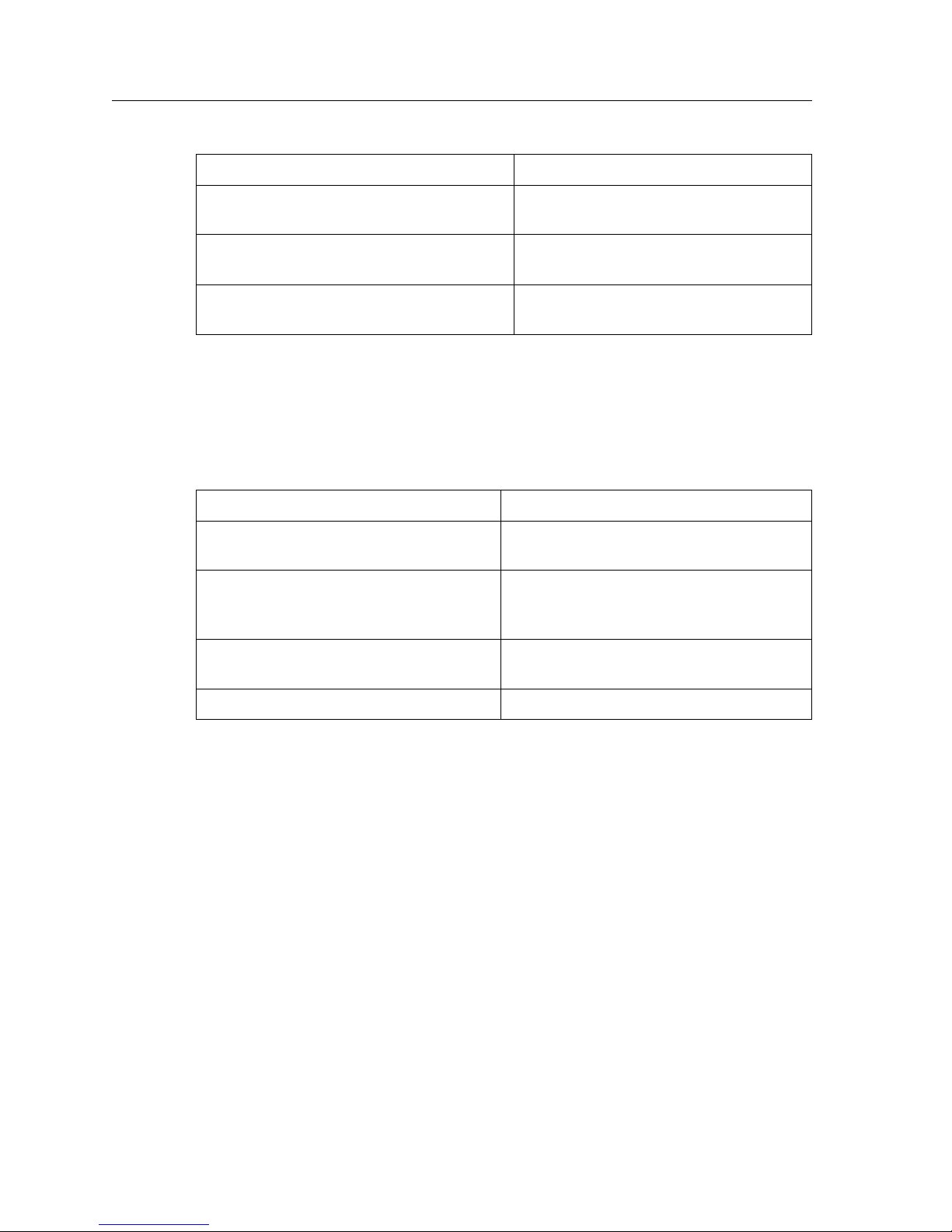
If You Want To... See...
Get an overview of the SSR 8000 and SSR
8600 software and hardware features
Install the SSR 8000 or SSR 8600 hardware Chapter 2, “Hardware Installation” on
Install the SSR 8000 or SSR 8600 software,
boot the software, and set up the unit
Set up the SSR 8000 or SSR 8600 for
management using CoreWatch
Chapter 1, “Features Overview” on page
3
page 51
Chapter 3, “Software Installation and
Setup” on page 81
Chapter 4, “Installing and Starting
Cabletron CoreWatch” on page 101
SSR 8000/8600 Getting Started Guide 1
Page 16
About This Guide
If You Want To... See...
Troubleshoot installation problems Appendix A, “Troubleshooting” on page
Contact Cabletron Technical Support Appendix B, “Technical Support” on
107
page 111
Contact Cabletron Systems for technical
support
Related Documentation
The Cabletron Systems documentation set includes the following items. Refer to these
other documents to learn more about your product.
For Information About... See the...
Managing the SSR 8000 or SSR 8600 using
the CoreWatch application
How to use Command Line Interface
(CLI) commands to configure and
manage the SSR 8000 or SSR 8600
The complete syntax for all CLI
commands
SYSLOG messages SmartSwitch Router Error Reference Manual
Appendix B, “Technical Support” on
page 111
CoreWatch User’s Manual and the
CoreWatch online help
SmartSwitch Router User Reference Manual
SmartSwitch Router Command Line Interface
Reference Manual
2 SSR 8000/8600 Getting Started Guide
Page 17

Chapter 1
Features Overview
The 8-slot and 16-slot SSR (SSR 8000 and SSR 8600) provide non-blocking, wire-speed
Layer-2 (switching), Layer-3 (routing) and Layer-4 (application) switching. This chapter
provides a basic overview of the SmartSwitch Router (SSR) software and hardware feature
set.
• If you want to skip this information and install the SSR now, see Chapter 2, “Hardware
Installation” on page 51.
• If you want to boot the SSR software and perform basic configuration tasks now, see
Chapter 3, “Software Installation and Setup” on page 81.
• If you want to set up a management station for using CoreWatch, see Chapter 4,
“Installing and Starting Cabletron CoreWatch” on page 101.
SSR 8000/8600 Getting Started Guide 3
Page 18

Chapter 1: Features Overview
Specifications
The SSR provides wire-speed switching and full non-blocking throughput. The hardware
provides wire-speed performance regardless of the performance monitoring, filtering, and
Quality of Service (QoS) features enabled by the software. You do not need to accept
performance compromises to run QoS or access control lists (ACLs).
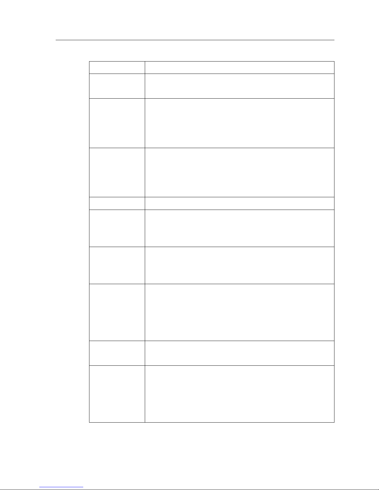
The following table lists the basic hardware and software specifications for the SSR.
Feature Specification
Throughput • 16-Gbps non-blocking switching fabric (SSR 8000)
• 32-Gbps non-blocking switching fabric (SSR 8600)
• Up to 30 million packets-per-second routing throughput (SSR
8600)
• Up to 15 million packets-per-second routing throughput (SSR
8000)
Capacity • Up to 250,000 routes
• Up to 2,000,000 Layer-4 application flows (SSR 8000)
• Up to 4,000,000 Layer-4 application flows (SSR 8600)
• 400,000 Layer-2 MAC addresses (SSR 8000)
• 800,000 Layer-2 MAC addresses (SSR 8600)
• 4,096 Virtual LANs (VLANs)
• 20,000 Layer-2 security and access-control filters
• 3 MB input/output buffering per Gigabit port
• 1 MB input/output buffering per 10/100 port
• 20 MB shared input/output buffering across WAN ports on a
WAN mo du le
• 32 MB input/output buffering per Packet Over SONET/SDH
OC-3c port
• 64 MB input/output buffering per Packet Over SONET/SDH
OC-12c port
Routing
protocols
• IP: RIP v1/v2, OSPF, BGP 2, 3, 4
• IPX: RIP, SAP
4 SSR 8000/8600 Getting Started Guide
• Multicast: IGMP, DVMRP
Page 19
Feature Specification
Chapter 1: Features Overview
Bridging and
• 802.1d Spanning Tree
VLAN protocols
• 802.1Q (VLAN trunking)
Media interface
• 802.3 (10Base-T)
protocols
• 802.3u (100Base-TX, 100Base-FX)
• 802.3x (1000Base-SX, 1000Base-LX)
• 802.3z (1000Base-SX, 1000Base-LX)
Quality of
• Layer-2 prioritization (802.1p)
Service (QoS)
• Layer-3 source-destination flows
• Layer-4 source-destination flows
• Layer-4 application flows
RMON • RMON v1/v2 for each port
Management • SNMP
• CoreWatch software (GUI)
• Emacs-like Command Line Interface (CLI)
Port mirroring • Traffic to the Control Module
• Traffic from specific ports
• Traffic to specific chassis slots (line cards)
Hot swapping • Line cards
• Control Module (when redundant Control Module is installed
and online)
• Switching Fabric Modules (SSR 8600 only)
• Power Supply (when redundant supply is installed and online)
Load balancing/
• Cabletron Systems SmartTRUNK support
sharing
• Load Sharing Network Address Translation (LSNAT)
Redundancy • Redundant and hot-swappable power supplies
• Redundant and hot-swappable Control Modules
• Redundant and hot-swappable Switching Fabric Modules (SSR
8600 only)
• Virtual Router Redundancy Protocol (VRRP)
SSR 8000/8600 Getting Started Guide 5
Page 20
Chapter 1: Features Overview
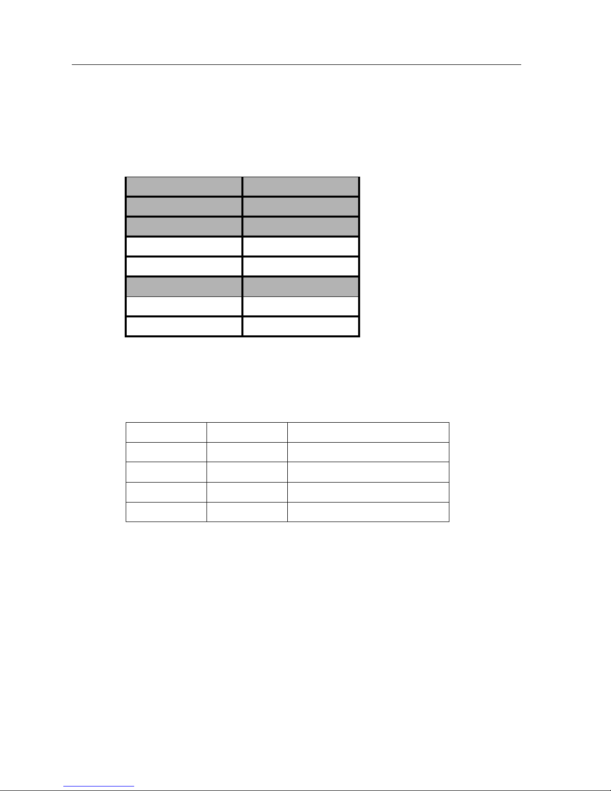
This guide and other SSR documentation refers to the SSR’s Layer-2 (L2), Layer-3 (L3),
and Layer-4 (L4) switching and routing. These layers are based on the International
Standards Organization (ISO) 7-layer reference model. Here is an example of that model.
The SSR operates within the layers that are not shaded. Notice that Layer 2 is divided into
an LLC layer and a MAC layer. The SSR operates at the MAC layer but not the LLC layer.
Layer 7 Application
Layer 6 Presentation
Layer 5 Session
Layer 4 TCP/UDP - application
Layer 3 IP/IPX - routing
Layer 2 LLC
Layer 2 MAC -bridging
Layer 1 Physical Interfaces
TCP/UDP Services
The following table lists some well-known TCP/UDP services provided by the SSR.
TCP Port UDP Port Description
23 Telnet
161 SNMP
67 BOOTP/DHCP Relay Agent
520 Routed
6 SSR 8000/8600 Getting Started Guide
Page 21

Features
This section describes the following SSR features:
• Address-based and flow-based bridging
• Port-based VLANs and protocol-based VLANs
• IP and IPX routing
• Layer-4 (application) switching
•Security
• Quality of Service (QoS)
• Statistics
• Management
Bridging
Chapter 1: Features Overview
The SSR provides the following types of wire-speed bridging:
• Address-based bridging – The SSR performs this type of bridging by looking up the
destination address in an L2 lookup table on the line card that receives the bridge
packet from the network. The L2 lookup table indicates the exit port(s) for the bridged
packet. If the packet is addressed to the SSR’s own MAC address, the packet is routed
rather than bridged.
• Flow-based bridging – The SSR performs this type of bridging by looking up an entry
in the L2 lookup table containing both the source and destination addresses of the
bridge packet.
Your choice of bridging method does not affect SSR performance. However, addressbased bridging is more efficient because it requires fewer table entries while flow-based
bridging provides tighter management and control over bridged traffic.
The SSR ports perform address-based bridging by default but can be configured to
perform flow-based bridging, instead of address-based bridging, on a per-port basis. A
port cannot be configured to perform both types of bridging at the same time.
SSR 8000/8600 Getting Started Guide 7
Page 22

Chapter 1: Features Overview
Port and Protocol VLANs
The SSR supports the following types of Virtual LANs (VLANs):
• Port-based VLANs – A port-based VLAN is a set of ports that comprises a Layer-2
broadcast domain. The SSR confines MAC-layer broadcasts to the ports in the VLAN
on which the broadcast originates. SSR ports outside the VLAN do not receive the
broadcast.
• Protocol-based VLANs – A protocol-based VLAN is a named set of ports that
comprises an IP or IPX broadcast domain. The SSR confines IP or IPX broadcasts to the
ports within the IP or IPX based VLAN. Protocol-based VLANs sometimes are called
subnet VLANs or Layer-3 VLANs.
You can include the same port in more than one VLAN, even in both port-based and
protocol-based VLANs. Moreover, you can define VLANs that span across multiple SSRs.
To simplify VLAN administration, the SSR supports 802.1Q trunk ports, which allow you
to use a single port to “trunk” traffic from multiple VLANs to another SSR or switch
which supports 802.1Q.
Routing
The SSR provides wire-speed routing for the following protocols:
• Internet Protocol (IP) – protocol that switching and routing devices use for moving
traffic within the Internet and within many corporate intranets
• Internet Packet Exchange (IPX) – protocol by Novell used in NetWare products
Note:
By default, the SSR uses one MAC address for all interfaces. The SSR can be configured to
have a separate MAC address for each IP interface and a separate MAC address for each
IPX interface. When the SSR receives a packet whose destination MAC address is one of
the SSR’s IP or IPX interface MAC addresses, the line card that received the packet from
the network uses information in the line card’s L3 lookup tables (or information supplied
by the Control Module) to route the packet to its IP destination(s). (See “Control Module”
on page 14 for information about the Control Module.)
You can create only one IP and IPX interface on a single port or VLAN. You can add
secondary IP addresses to the same IP interface. When you add an interface to a set of
ports, you are adding a VLAN to those ports. Ports that contain IP and IPX interfaces can
also still perform Layer-2 bridging.
All other protocols that require routing must be tunneled using IP.
8 SSR 8000/8600 Getting Started Guide
Page 23

IP Routing
The SSR supports the following IP unicast routing protocols:
• RIP v1 and RIP v2
•OSPF v2
•BGP 2,3,4
IP interfaces do not use a specific routing protocol by default. When you configure an
interface for routing, you also specify the routing protocol the interface will use.
IP Multicast Routing
The SSR supports the following IP multicast routing protocols:
•IGMP
•DVMRP
Chapter 1: Features Overview
The SSR does not use a specific IP Multicast routing protocol by default. When you
configure an interface for IP Multicast, you also specify the routing protocol you want the
interface to use.
IPX Routing
The SSR supports the following IPX routing protocols:
•IPX RIP – a version of the Routing Information Protocol (RIP) tailored for IPX
• IPX SAP – the Service Advertisement Protocol, which allows hosts attached to an IPX
network to reach printers, file servers, and other services
By default, IPX routing is enabled on the SSR when an IPX interface is created.
Layer-4 Switching
In addition to Layer-2 bridging and Layer-3 routing, the SSR performs Layer-4 switching.
Layer-4 switching is based on applications and flows.
• Layer-4 applications – The SSR understands the application for which an IP or IPX
packet contains data and therefore enables you to manage and control traffic on an
application basis. For IP traffic, the SSR looks at the packet’s TCP or UDP port number
to determine the application. For IPX packets, the SSR looks at the destination socket
to determine the application.
• Layer-4 flows – The SSR can store Layer-4 flows on each line card. A Layer-4 flow
consists of the source and destination addresses in the IP or IPX packet combined with
SSR 8000/8600 Getting Started Guide 9
Page 24

Chapter 1: Features Overview
the TCP or UDP source and destination port number (for IP) or the source and
destination socket (for IPX). You can therefore manage and control individual flows
between hosts on an individual application basis.
A single host can have many individual Layer-4 entries in the SSR. For example, an IP
host might have separate Layer-4 application entries for email, FTP, HTTP, and so on, or
separate Layer-4 flow entries for specific email destinations and for specific FTP and Web
connections.
Security
The bridging, routing, and application (Layer-2, Layer-3, and Layer-4) support described
in previous sections enables you to implement security filters that meet specific needs.
You can implement the following types of filters to secure traffic on the SSR.
• Layer-2 source filters (block bridge traffic based on source MAC address)
• Layer-2 destination filters (block bridge traffic based on destination MAC address)
• Layer-2 flow filters (block bridge traffic based on specific source-destination pairs)
• Layer-3 source filters (block IP or IPX traffic based on source IP or IPX address)
• Layer-3 destination filters (block IP or IPX traffic based on destination IP or IPX
address)
• Layer-3 flow filters (block IP or IPX traffic based on specific source-destination pairs)
• Layer-4 flow filters (block traffic based on application flows)
• Layer-4 application filters (block traffic based on UDP or TCP source and destination
ports for IP or source and destination sockets for IPX)
Quality of Service
Although the SSR supplies non-blocking wire-speed throughput, you can configure the
SSR to apply Quality of Service (QoS) policies during peak periods to guarantee service to
specific hosts, applications, and flows (source-destination pairs). This is especially useful
in networks where the traffic level can exceed the network medium’s capacity.
The SSR QoS is based on four queues: control, high, medium, and low. Control traffic has
the highest priority, high the second highest, and so on. The default priority for all traffic
is low.
10 SSR 8000/8600 Getting Started Guide
Page 25

Statistics
Chapter 1: Features Overview
You can configure QoS policies for the following types of traffic:
• Layer-2 prioritization (802.1p)
• Layer-3 source-destination flows
• Layer-4 source-destination flows
• Layer-4 application flows
The SSR can provide extensive statistical data on demand. You can access the following
types of statistics:
• Layer-2 RMON and MIB II Statistics – Port statistics for normal packets and for errors
(packets in, packets out, CRC errors, and so on)
• Layer-3 RMON v2 Statistics – Statistics for ICMP, IP, IP-interface, IP routing, IP
multicast, VLAN
• Layer-4 RMON v2 Statistics – Statistics for TCP and UDP
Management Platforms
You can manage the SSR using the following management platforms:
• Command Line Interface (CLI) – An Emacs editor-like interface that accepts typed
commands and responds when applicable with messages or tables. You will use the
CLI to perform the basic setup procedures described in Chapter 3 of this guide.
• CoreWatch – Cabletron Systems’s Java-based device management software.
CoreWatch provides a graphical interface to the SSR, providing most of the same
monitoring and control features as the CLI.
• SNMP MIBs and traps – The SSR supports SNMP v1 and many standard networking
MIBs. You access the SSR’s SNMP agent using integration software for HP OpenView
5.x on Windows NT or Solaris 2.x, or Cabletron SPECTRUM on Solaris 2.x. Chapter 3
in this guide explains how to set up SNMP on the SSR. Chapter 4 explains how to
access the SSR’s SNMP agents.
SSR 8000/8600 Getting Started Guide 11
Page 26
Chapter 1: Features Overview
Hardware Overview
This section describes the SSR hardware modules with which you will be working.
Chapter 2 in this guide describes how to install the hardware. This section describes the
following hardware:
• Chassis, Backplane, and Fan module
• Control Module
• Power Supply
• Switching Fabric Module (SSR 8600 only)
•Line cards
Chassis
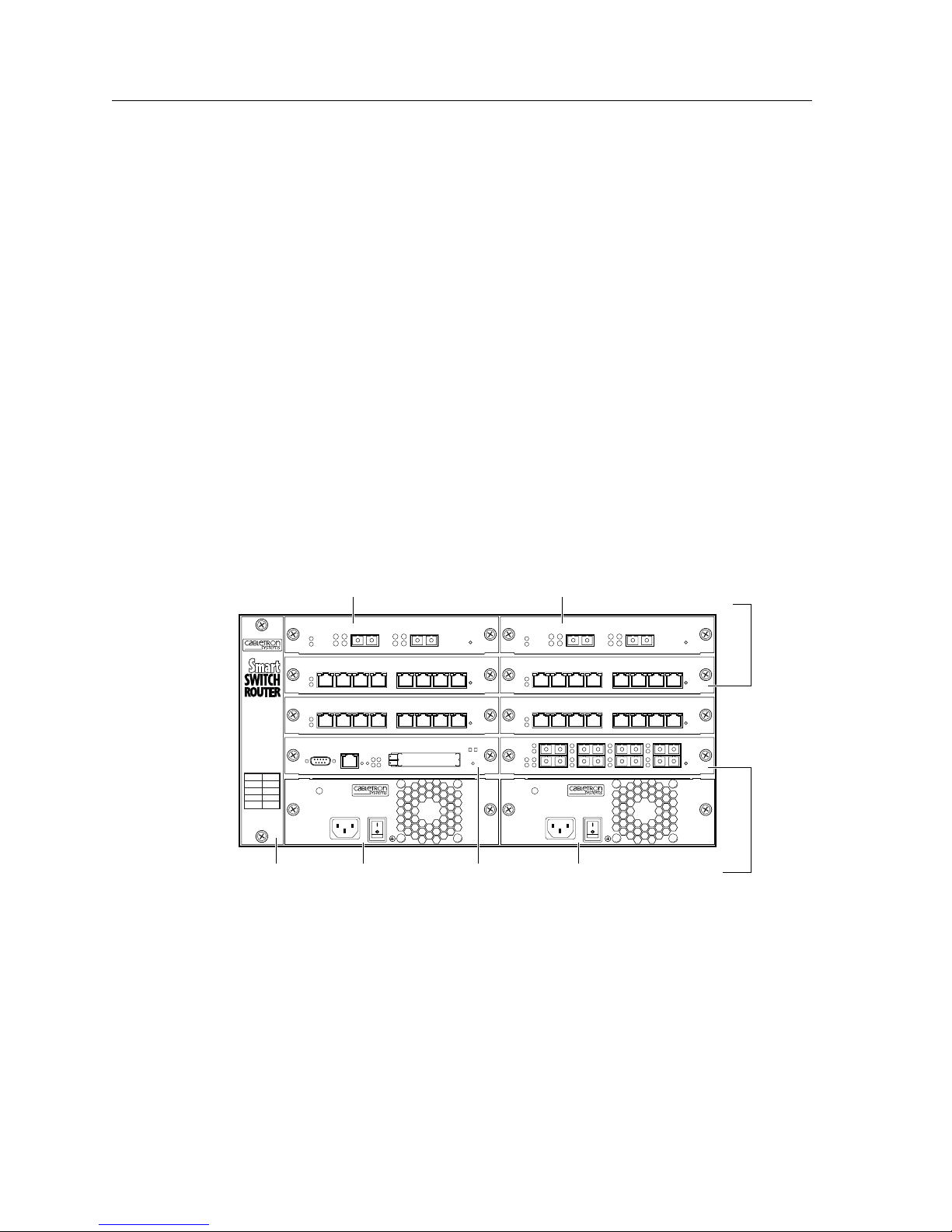
Figure 1 shows the front view of a fully loaded SSR 8000 chassis. The SSR 8000 chassis
contains eight slots, numbered from 0 to 7. Slot 0 is in the lower left corner of the chassis
and slot 7 is in the upper right corner.
Gigabit-SX module 10/100 BASE-TX
3
4
21
PWR
SSR-PS-8
100-125~5A
200-240~3A
50-60 Hz
6
7
4
5
2
3
CM/1
CM
PS2PS1
SSR-8
Gigabit-LX module
1000BASE-LXSSR-GLX19-02
21 21
10/100BASE-TXSSR-HTX12-08
87654321 87654321
10/100BASE-TXSSR-HTX12-08
87654321 87654321
SSR-CM-2 CONTROL MODULE
PWR
SSR-PS-8
100-125~5A
200-240~3A
50-60 Hz
Fan module Power supply Control module Power supply
Figure 1. Front view of a fully loaded SSR 8000 chassis
1000BASE-SXSSR-GSX11-02
10/100BASE-TXSSR-HTX12-08
10/100BASE-TXSSR-HTX12-08
87
5
6
100 BASE-FX
module
100BASE-FXSSR-HFX11-08
module
12 SSR 8000/8600 Getting Started Guide
Page 27
Chapter 1: Features Overview
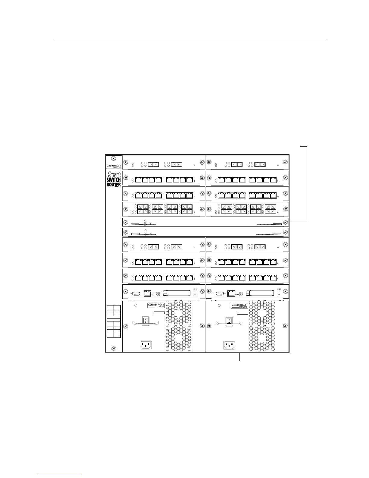
Figure 2 shows the front view of a fully loaded SSR 8600 chassis. The SSR 8600 chassis is
similar to the SSR 8000 chassis, except for the following:
• The chassis can contain up to 16 line cards.
• The switching fabric is stored on a separate module.
• There is a slot for a redundant switching fabric module.
• The power supply is larger.
Switching Fabric
module
1000BASE-LXSSR-GLX19-02 1000BASE-SXSSR-GSX11-02
21 21
14 15
12
13
10
11
8
9
Fabric 2
Fabric 1
6
7
4
5
2
3
CM/1
CM
PS2PS1
SSR-16
10/100BASE-TXSSR-HTX12-08
87654321 87654321
10/100BASE-TXSSR-HTX12-08
87654321 87654321
3
4
5
TO REMOVE POWER TO
UNIT DISCONNECT ALL
POWER SUPPLY CORDS
100-125V~ 10A
200-240V~ 6A
50/60 Hz
SSR-PS-16
SN
21
SSR-SF-16
SSR-SF-16
SSR-CM-2 CONTROL MODULE
PWR
100BASE-FXSSR-HFX11-08
87
6
1000BASE-LXSSR-GLX19-02 1000BASE-SXSSR-GSX11-02
21 21
10/100BASE-TXSSR-HTX12-08
87654321 87654321
10/100BASE-TXSSR-HTX12-08
87654321 87654321
10/100BASE-TXSSR-HTX12-08
10/100BASE-TXSSR-HTX12-08
3
4
5
21
SSR-CM-2 CONTROL MODULE
PWR
SSR-PS-16
SN
TO REMOVE POWER TO
UNIT DISCONNECT ALL
POWER SUPPLY CORDS
100-125V~ 10A
200-240V~ 6A
50/60 Hz
87
6
Switching Fabric
Switching Fabric
10/100BASE-TXSSR-HTX12-08
10/100BASE-TXSSR-HTX12-08
100BASE-FXSSR-HFX11-08
The SSR 8600 chassis contains sixteen slots, numbered from 0 to 15. Slot 0 is in the lower
left corner of the chassis and slot 15 is in the upper right corner. The SSR 8600 also has
slots for primary and redundant switching fabric modules.
SSR 8000/8600 Getting Started Guide 13
Power supply
Figure 2. Front view of a fully loaded SSR 8600 chassis
Page 28

Chapter 1: Features Overview
On both the SSR 8000 and SSR 8600, slot 0 is labeled “CM” and contains the primary
Control Module. The CM slot cannot be used for line cards. The primary Control Module
must be installed in this slot. The CM/1 slot can contain a redundant Control Module (if
you install one) or can contain a line card. Slots 2-7 on the SSR 8000 or slots 2-15 on the SSR
8600 can contain any line cards. (See “Control Module” on page 14 and “Line Cards” on
page 20 for information about these items.)
You can install line cards in any order in the slots. For example, you could install line cards
in slots 2 and 5 and leave the other line card slots empty. The SSR provides non-blocking
throughput regardless of the software features you are using. Therefore, you do not need
to “load balance” line cards by placing them in certain relationships to balance the load on
the backplane. Regardless of where you install the line cards, the backplane can provide
full, non-blocking throughput.
Backplane
The backplane occupies the rear of the chassis and connects the power supplies, Control
Modules, and line cards together. The power supplies use the backplane to provide power
to the rest of the system. The line cards and Control Modules use the backplane to
exchange control information and packets. The backplane is installed at the factory.
Contact Cabletron Systems if you wish to replace the backplane.
Fan Module
The SSR contains a fan module to provide a cooling air flow across the Control Module(s)
and line cards. The fan module is located on the left side of the Control Modules and line
cards. The SSR 8000 fan module contains two fans; the SSR 8600 fan module contains six
fans. The fan module is installed at the factory, but you can replace the module yourself, if
necessary.
Note:
To ensure that the fan module can provide adequate cooling, always provide a
minimum of 3 inches of clearance on each side of the chassis.
Control Module
The Control Module is the SSR’s central processing unit. It contains system-wide bridging
and routing tables. Traffic that does not yet have an entry in the L2 and L3/L4 lookup
tables on individual line cards is sent to the Control Module. After processing traffic, the
Control Module updates the L2 and L3/L4 tables on the line cards that received the traffic.
The line cards thus “learn” about how to forward traffic.
14 SSR 8000/8600 Getting Started Guide
Page 29
Boot Flash
Chapter 1: Features Overview
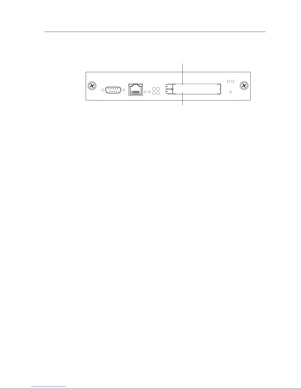
Figure 3 shows the front panel of the Control Module.
PCMCIA slot 0
SSR-CM-2 CONTROL MODULE
Console
10/100 Mgmt
RST
OK
SYS
ERR DIAG
HBT
Online Offline
Hot
Swap
PCMCIA slot 1
Figure 3. Front panel of the Control Module
The Control Module has a boot flash containing the SSR’s boot software and configuration
files. The system software image file resides on a PCMCIA card or a TFTP server.
Memory Module
The Control Module uses memory to hold the routing tables and other tables. The
minimum factory configuration for the Control Module includes 64MB of memory (in a
64MB DIMM). You can obtain SSR memory upgrade kits from Cabletron Systems to
increase memory to 128MB (in a 128MB DIMM), 192MB (in one 64MB DIMM and one
128MB DIMM), or 256MB (in two 128MB DIMMs). See “Installing a Memory Upgrade” on
page 64 for the upgrade procedure.
SSR 8000/8600 Getting Started Guide 15
Page 30
Chapter 1: Features Overview
External Controls
The Control Module has the following external controls. Where appropriate, this guide
describes how to use the controls.
• Male DB-9 Data Communications Equipment (DCE) port for serial connection from a
management terminal. Use this port to establish a direct CLI connection to the SSR. The
default baud rate is 9600.
• 10/100Base-TX Data Terminal Equipment (DTE) port for network (“in-band”)
connection from a management terminal. The port is configured as a Media Data
Interface (MDI). Use this port to establish a CoreWatch management connection to the
SSR over a local or bridged Ethernet segment.
• Reset switch (RST). Use this switch to reboot the SSR’s CPU.
• Status LEDs. These LEDs indicate whether the Control Module is online or offline.
• PCMCIA
upgrades as well as older system image software versions.
Note: You can install a PCMCIA card in either slot but you cannot use two PCMCIA
cards at the same time.
AC Power Supply
The power supply delivers 3.3, 5, and 12 DC volts to the SSR’s Control Module(s), fan
modules, and other components. A single power supply provides enough current to
operate a fully-configured chassis. The power supply has its own internal cooling fan. The
vent on the front of the power supply is the inlet vent for the cooling fan.
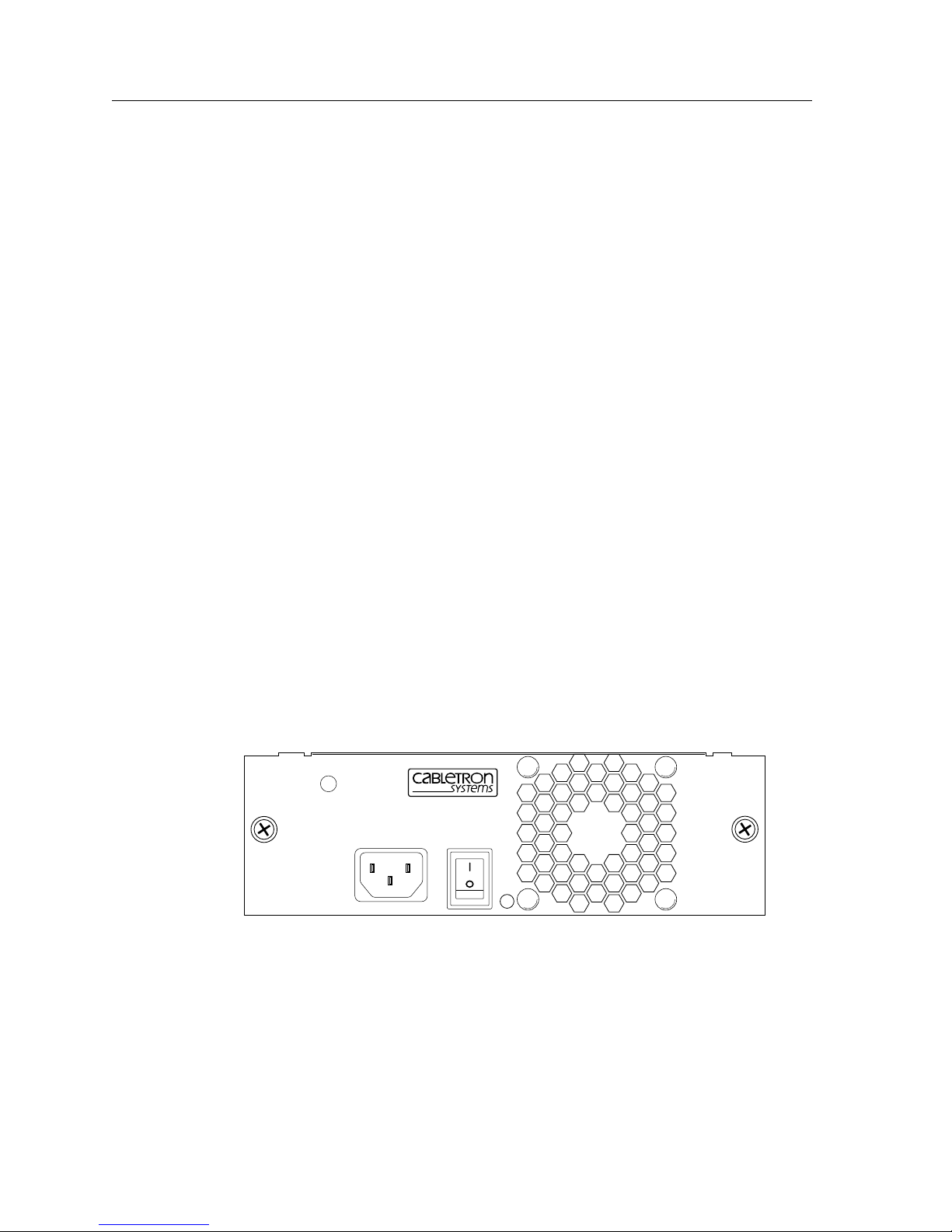
Figure 4 shows the front view of an SSR 8000 AC power supply.
flash memory slots. These slots let you install system image software
PWR
100-125~5A
200-240~3A
50-60 Hz
SSR-PS-8
Figure 4. Front view of an SSR 8000 AC power supply
16 SSR 8000/8600 Getting Started Guide
Page 31
Chapter 1: Features Overview
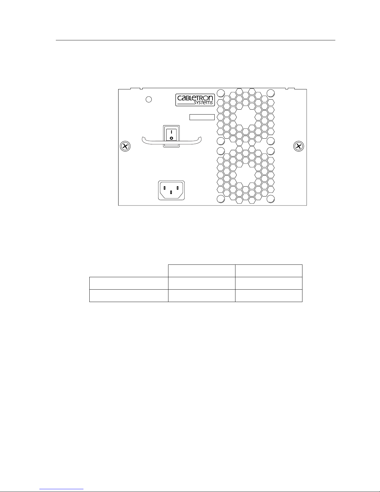
The SSR 8600 power supply is somewhat larger than the SSR 8000 power supply. Figure 7
shows the front view of an SSR 8600 AC power supply.
PWR
SSR-PS-16
SN
TO REMOVE POWER T O
UNIT DISCONNECT ALL
POWER SUPPLY CORDS
100-125V~ 10A
200-240V~ 6A
50/60 Hz
Figure 5. Front view of an SSR 8600 AC power supply
The following table lists the specifications for the SSR’s AC power supply.
SSR 8000 SSR 8600
Input voltage 100-125, 200-240 VAC 100-125, 200-240 VAC
Input current (maximum) 5, 3 A 10, 6 A
To ensure against equipment failure, you can install a redundant power supply. When two
power supplies are active in the SSR, they load share, each supply delivering
approximately 50 percent of the current needed. Moreover, if one of the power supplies
fails, the other power supply immediately assumes the entire load, thus preventing any
system outage.
The AC power supply has a green status LED. When the LED is lit, the power supply is
connected to an appropriate power source and is active. The status LED is lit when you
switch the power supply on, not when you plug the power supply into a power source.
SSR 8000/8600 Getting Started Guide 17
Page 32
Chapter 1: Features Overview
DC Power Supply
The SSR DC power supply delivers 3.3, 5, and 12 volts DC to the SSR’s Control Module(s),
fan modules, and other components. A single DC power supply provides enough current
to operate a fully-configured chassis.
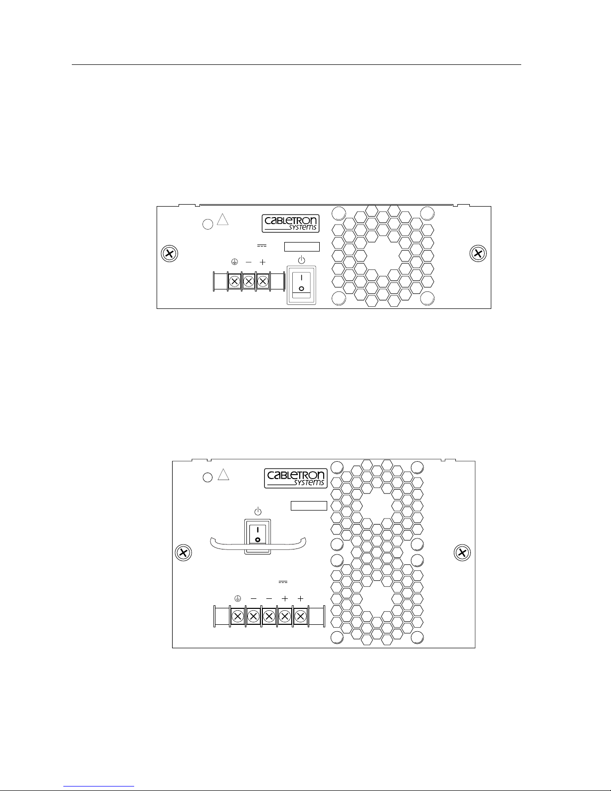
Figure 6 shows the front view of an SSR 8000 DC power supply.
To be installed in a restricted
access area in accordance
with the NEC or authority
!
having jurisdiction.
See manual for installation
instructions.
PWR
48/60V
14A MAX
SSR-PS-8-DC
SN
Figure 6. Front View of an SSR 8000 DC Power Supply
The SSR 8000 DC power supply has a three-terminal wiring block on the front panel,
consisting of a positive(+) terminal, negative(-) terminal and a safety ground. The DC
supply is designed to be powered by a 48 Volt DC source. 12 to 14 gauge wire should be
used to connect the 48 Volt source to the SSR 8600 DC power supply. 12 to 14 gauge wire
should also be used for the safety ground.
Figure 7 shows the front view of an SSR 8600 DC Power Supply.
To be installed in a restricted
access area in accordance
with the NEC or authority
!
having jurisdiction.
See manual for installation
PWR
instructions.
SSR-PS-16-DC
SN
48/60V
27A MAX
Figure 7. Front View of an SSR 8600 DC Power Supply
18 SSR 8000/8600 Getting Started Guide
Page 33
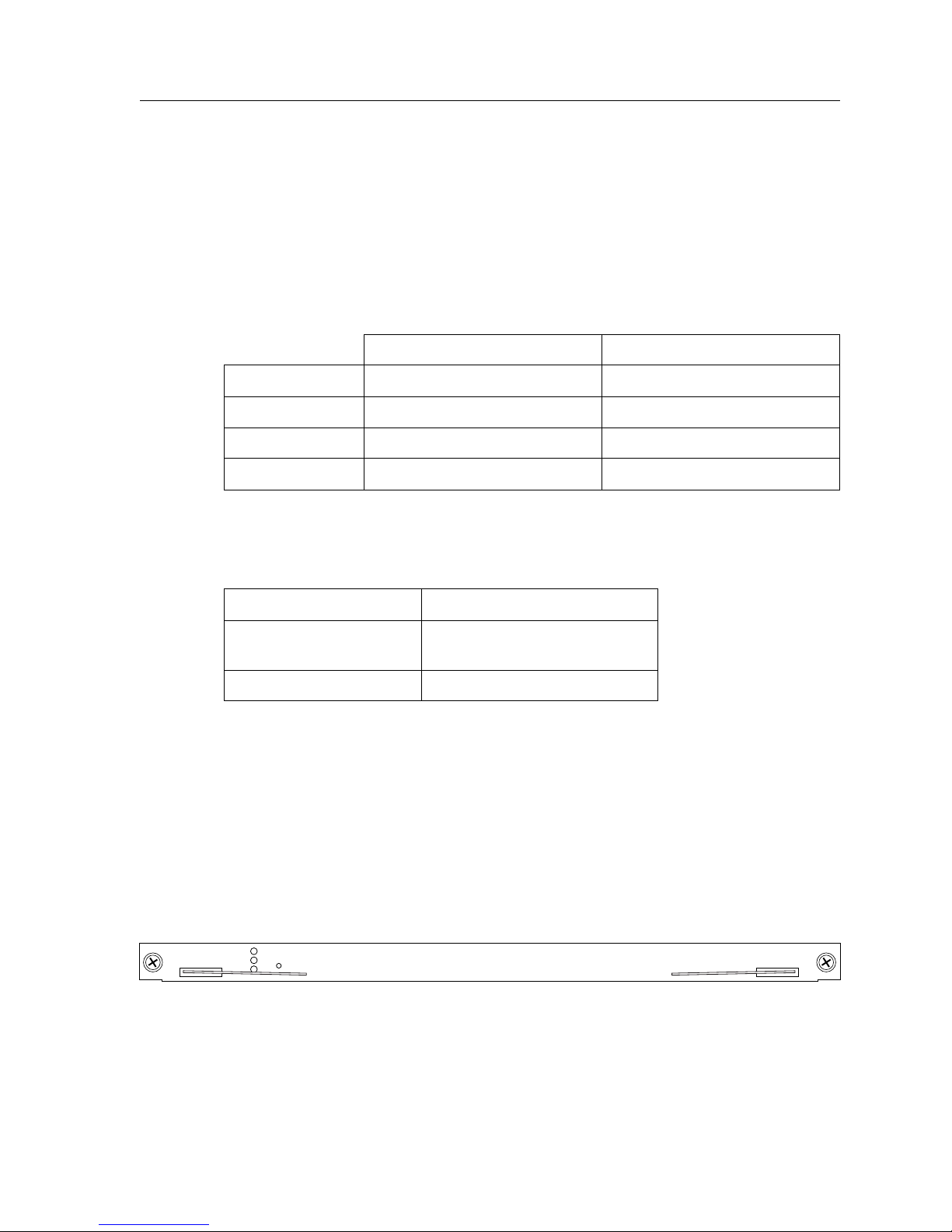
The SSR 8600 DC power supply has a five-terminal wiring block on the front panel,
consisting of two positive(+) terminal, two negative(-) terminal and a safety ground. The
DC supply is designed to be powered by a 48 Volt DC source.
DC Power Supply Specifications
The following table lists the physical specifications for the SSR’s DC Power Supplies.
Dimensions 11.00" (L) x 7.70" (W) x 2.55" (H) 12.15" (L) x 7.70" (W) x 5.05" (H)
Weight 6.5 lbs. (2.95 kg) 12.0 lbs. (5.45 kg)
Power Output 300 W 600 W
Voltage Range 36-72V, 14 A @ 48 V nominal 36-72V, 27 A @ 48 V nominal
The following table lists the environmental specifications for the SSR’s DC Power
Supplies
Chapter 1: Features Overview
SSR 8000 SSR 8600
Operating Temperature +5° to +40°C (41° to 104°F)
Non-operating
-30° to +73°C (-22° to 164°F)
temperature
Operating Humidity 15% to 90% (non-condensing)
Switching Fabric Module (SSR 8600 only)
On the SSR 8600, the switching fabric is contained on a separate plug-in module. The SSR
8600 has slots for two of these modules. When two switching fabric modules are installed,
the module in the slot labelled “Fabric 1” serves as the primary switching fabric module,
and the module in the slot labelled “Fabric 2” serves as a redundant switching fabric
module.
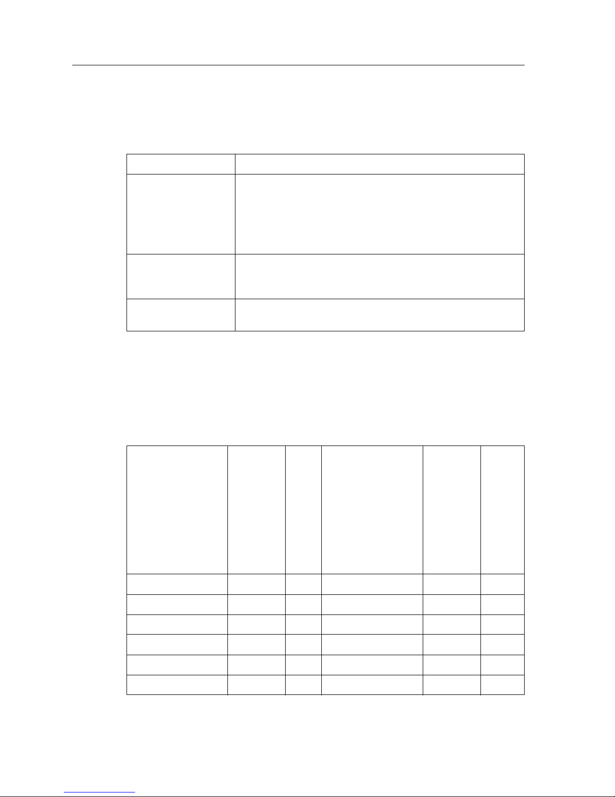
Figure 8 shows the front panel of the SSR 8600 Switching Fabric module.
SSR-SF-16
Offline
Online
Active
Hot
Swap
Figure 8. Front panel of SSR 8600 Switching Fabric Module
Switching Fabric
SSR 8000/8600 Getting Started Guide 19
Page 34
Chapter 1: Features Overview
LEDs
The SSR 8600 Switching Fabric module uses the following LEDs.
LED Description
Offline When lit, this amber LED indicates that the module is offline
Online When lit, this green LED indicates that the module is online
Active When lit, this LED indicates that the switching fabric module
(powered off) and is ready for hot swap.
The Offline LED also is lit briefly during a reboot or reset of the
SSR and goes out as soon as the Control Module discovers and
properly initializes the switching fabric module.
and is ready to receive, process, and send packets if configured
to do so.
is actively receiving, processing, and sending packets.
Line Cards
The following table lists the line cards available for the SSR. The line cards are equipped
with 4 MB, 16 MB, or 32MB of RAM.
SSR Part Number All pre
3.0 SSR
Firmware
Release
Non AA Cards
SSR-HTX12-08 X X
SSR-HTX22-08 X X
SSR-HFX11-08 X X
WFQ 3.0 SSR Firmware
NAT, LSNAT, QoS,
Rate Limiting, TOS
Rewrite, Per
Protocol VLANs,
Established Bit
ACL
SSR 3.1 Firmware
L4 Bridging, Mult
IPX Encap
Routing
Ta b l e o n
line card,
WRED,
Per Port
Rate
Limiting
Jumbo
Frame
SSR-HFX21-08 X X
SSR-HFX29-08 X X
20 SSR 8000/8600 Getting Started Guide
Page 35

SSR-GSX11-02 X
SSR-GSX21-02 X
SSR-GLX19-02 X
SSR-GLX29-02 X
SSR-GLX70-01 X
SSR-SERC-04 X X
SSR-SERCE-04 X X
SSR-HSSI-02 X X
AA Cards
SSR-HTX12-08-AA X X X
SSR-HTX22-08-AA X X X
SSR-HFX21-08-AA X X X
Chapter 1: Features Overview
SSR-HFX29-08-AA X X X
SSR-GSX21-02-AA X X
SSR-GLX29-02-AA X X
SSR-GLX70-01-AA X X
SSR-SERC-04-AA X X X
SSR-SERCE-04-AA X X X
SSR-HSSI-02-AA X X X
T-Series Cards
SSR-POS21-04 X X X X X
SSR-POS29-04 X X X X X
SSR-POS31-02 X X X X X
SSR-POS39-02 X X X X X
SSR-ATM29-02 X X X X X
SSR-HTX32-16 X X X X
SSR-GSX31-02 X X X X X
SSR-GLX39-02 X X X X X
SSR-GTX32-02 X X X X X
SSR 8000/8600 Getting Started Guide 21
Page 36
Chapter 1: Features Overview
Note: The ATM line card supports a various number of physical interfaces (PHY).
Different PHYs can be installed into the ATM line card. The PHY types supported
are: DS-3/T-3, E-3, T-1, E-1, OC-3c MMF, OC-3c SMF, and OC-3c UTP.
The T- Se r ie s line cards are considered the next generation line card family for the SSR
Smart Switch Routers. The T-Series enhancements are as follows:
• Local hardware routing table support for more than 200,000 routes on each module
• Jumbo frames support up to 64,000 bytes
• Port Rate Limiting and Aggregate Rate Limiting
• Weighted Fair Queuing
• Weighted Random Early Detection
An SSR with every slot filled with 4 MB line cards provides 500,000 flows on the SSR 8000
and 1,000,000 flows on the SSR 8600. An SSR with every slot filled with 16 MB line cards
provides 2,000,000 flows on the SSR 8000 and 4,000,000 flows on the SSR 8600.
10/100Base-TX Line Card
The 10/100Base-TX line card contains eight independent Ethernet ports. Each port senses
whether it is connected to a 10-Mbps segment or a 100-Mbps segment and automatically
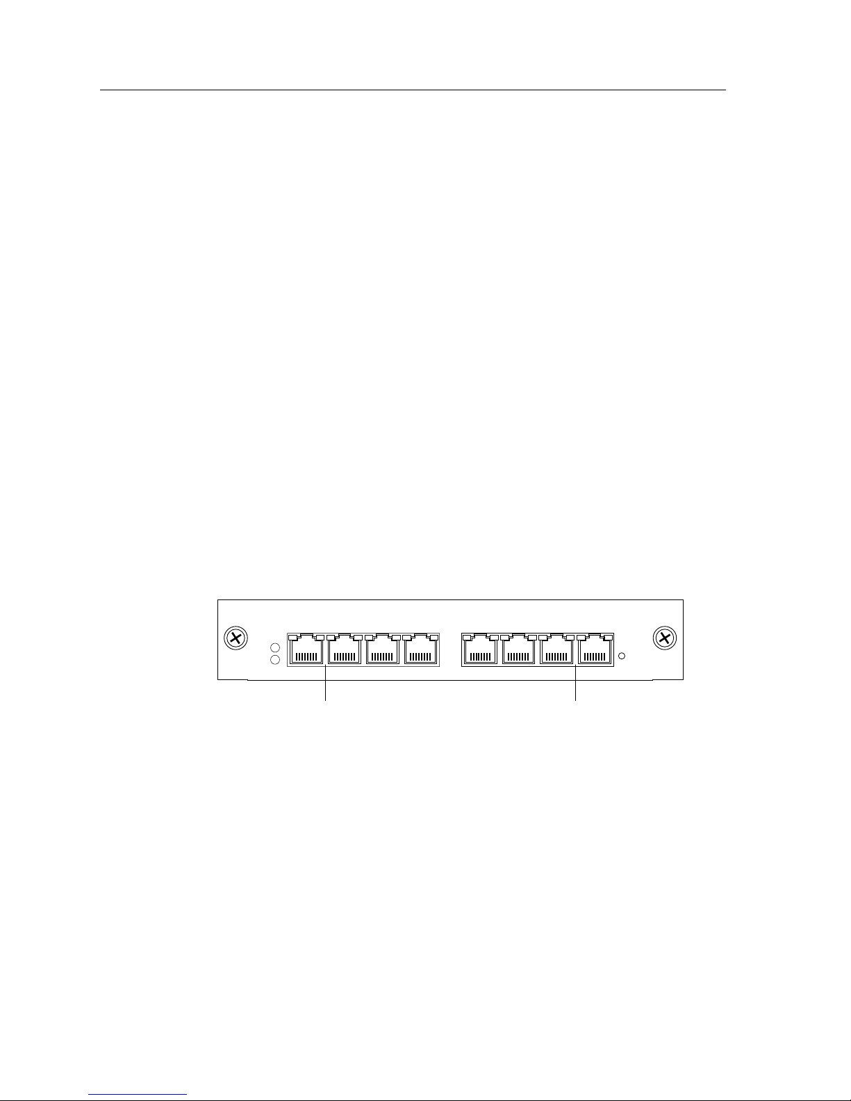
configures itself as a 10Base-T or 100Base-TX port. Figure 9 shows the front panel of the
10/100Base-TX line card.
10 BASE-T/100 BASE-TX ports 10 BASE-T/100 BASE-TX ports
Offline
Online
Figure 9. Front panel of 10/100Base-TX line card
10/100BASE-TXSSR-HTX12-08
87654321
Hot
Swap
22 SSR 8000/8600 Getting Started Guide
Page 37

Chapter 1: Features Overview
Cabling and Connector Specifications
The following table lists the media specifications for the 10/100Base-TX line card.
Port type Specification
10Base-T • 802.3 standard
• RJ-45 connector wired as Media Data Interface Crossed (MDIX);
see “10/100Base-TX Line Card” on page 72 for pin assignments
• EIA Category 3, 4, or 5 unshielded twisted pair cabling
• Maximum 100 meters (328 feet) segment length
100Base-TX • 802.3u standard
• RJ-45 connector wired as Media Data Interface Crossed (MDIX);
see “10/100Base-TX Line Card” on page 72 for pin assignments
• EIA Category 5 unshielded twisted pair cabling
• Maximum 100 meters (328 feet) segment length
LEDs
The 10/100Base-TX line card uses the following LEDs.
LED Description
Offline When lit, this amber LED on the left side of the line card
indicates that the line card is offline (powered off) and is ready
for hot swap.
The Offline LED also is lit briefly during a reboot or reset of the
SSR and goes out as soon as the Control Module discovers and
properly initializes the line card.
Online When lit, this green LED indicates that the line card is online
and is ready to receive, process, and send packets if configured
to do so.
Link Each port has two LEDs on its connector. The green LED on
the left side of the connector indicates the link status. When
this LED is lit, the port hardware is detecting that a cable is
plugged into the port and the port has established
communication with the device at the other end.
Activity The amber LED on the right side of each port connector flashes
each time the port’s transceiver sends or receives packets.
SSR 8000/8600 Getting Started Guide 23
Page 38
Chapter 1: Features Overview
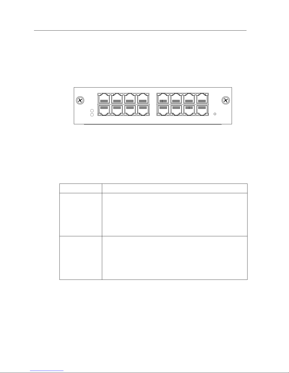
10/100Base-TX (T-Series) Line Card
The 10/100Base-TX 16-Port line card contains 16 independent Ethernet ports. Each port
senses whether it is connected to a 10-Mbps segment or a 100-Mbps segment and
automatically configures itself as a 10Base-T or 100Base-TX port. Figure 10 shows the front
panel of the 10/100Base-TX line card.
10/100BASE-TXSSR-HTX32-16
Offline
Online
Hot
Swap
161412108642
15131197531
Figure 10. Front panel of 10/100Base-TX (T-Series) line card
Cabling and Connector Specifications
The following table lists the media specifications for the 10/100Base-TX (T-Series) line
card.
Port type Specification
10Base-T • 802.3 standard
• RJ-45 connector wired as Media Data Interface Crossed (MDIX);
see “10/100Base-TX Line Card” on page 72 for pin assignments
• EIA Category 3, 4, or 5 unshielded twisted pair cabling
• Maximum 100 meters (328 feet) segment length
100Base-TX • 802.3u standard
24 SSR 8000/8600 Getting Started Guide
• RJ-45 connector wired as Media Data Interface Crossed (MDIX);
see “10/100Base-TX Line Card” on page 72 for pin assignments
• EIA Category 5 unshielded twisted pair cabling
• Maximum 100 meters (328 feet) segment length
Page 39
Chapter 1: Features Overview
LEDs
The 10/100Base-TX (T-Series) line card uses the following LEDs.
LED Description
Offline When lit, this amber LED on the left side of the line card
indicates that the line card is offline (powered off) and is ready
for hot swap.
The Offline LED also is lit briefly during a reboot or reset of the
SSR and goes out as soon as the Control Module discovers and
properly initializes the line card.
Online When lit, this green LED indicates that the line card is online
and is ready to receive, process, and send packets if configured
to do so.
Link Each port has two LEDs on its connector. The green LED on
the left side of the connector indicates the link status. When
this LED is lit, the port hardware is detecting that a cable is
plugged into the port and the port has established
communication with the device at the other end.
Activity The amber LED on the right side of each port connector flashes
each time the port’s transceiver sends or receives packets.
100Base-FX Line Cards (Multimode Fiber-optic Cable)
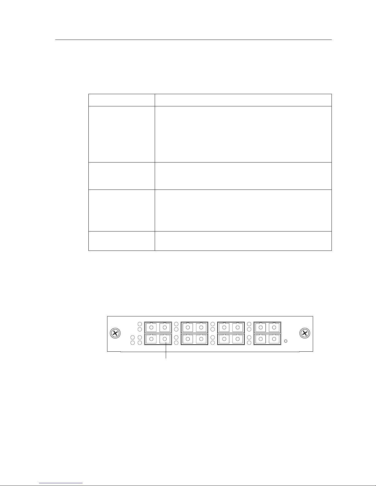
The 100Base-FX line cards provide the same features as the 10/100Base-TX line card but
use multimode fiber-optic cable (MMF) to connect to the network. The MMF line cards are
available in 4 MB and 16 MB versions. Figure 11 shows the front panel of the 4 MB
100Base-FX line card.
Offline
Online
Lnk
Act
Lnk
100 BASE-FX ports
Lnk
3
Act
Lnk
4
21
Figure 11. Front panel of 4 MB 100Base-FX line card (MMF)
Lnk
Act
Lnk
Lnk
Act
Lnk
5
100BASE-FXSSR-HFX11-08
87
Hot
Swap
6
SSR 8000/8600 Getting Started Guide 25
Page 40

Chapter 1: Features Overview
Cabling and Connector Specifications
The following table lists the media specifications for the 100Base-FX line card.
Port type Specification
100Base-FX • 802.3u standard
• SC-style Media Interface Connector (MIC); either connection
pin in the MIC can be used for transmit or receive; see
“1000Base-SX Line Card and 100Base-FX Line Card” on page 74
for attaching cables
• 62.5 micron multimode fiber-optic cable
• Maximum 412 meters (1352 feet) segment length for halfduplex links
• Maximum 2 kilometers (6562 feet) segment length for fullduplex links
LEDs
The 100Base-FX line card uses the following LEDs.
LED Description
Offline When lit, this amber LED on the left side of the line card
indicates that the line card is offline (powered off) but is ready
for hot swap.
The Offline LED also is lit briefly during a reboot or reset of the
SSR but goes out as soon as the Control Module discovers the
line card.
Online When lit, this green LED indicates that the line card is online
and is ready to receive, process, and send packets if configured
to do so.
Lnk Each port has two LEDs located to the left of the connector.
The green Lnk LED indicates the link status. When this LED is
lit, the port hardware is detecting that a cable is plugged into
the port and the port has established communication with the
device at the other end.
Act The amber Act LED flashes each time the port’s transceiver
sends or receives packets.
26 SSR 8000/8600 Getting Started Guide
Page 41
100Base-FX Line Card (Singlemode Fiber-optic Cable)
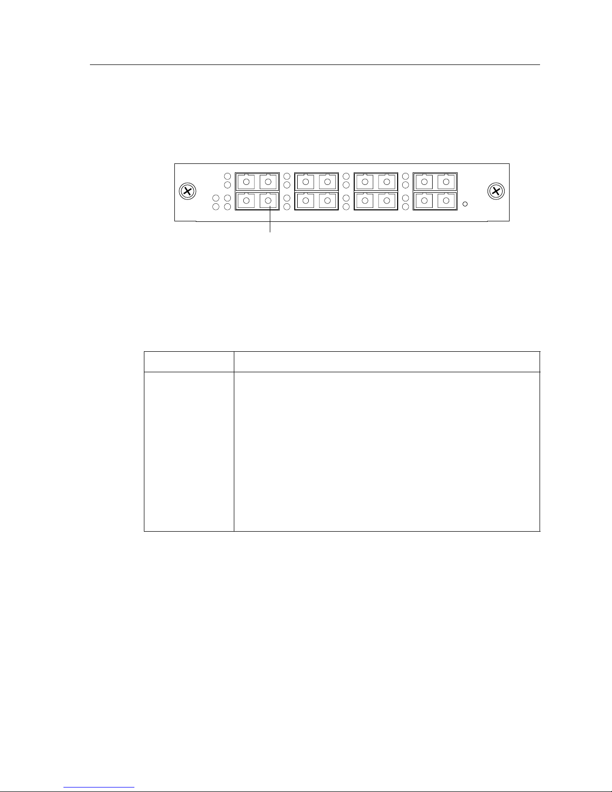
The SMF 100Base-FX line card uses singlemode fiber-optic cable (SMF) to connect to the
network. Figure 12 shows the front panel of the SMF 100Base-FX line card.
Chapter 1: Features Overview
Lnk
Act
Lnk
5
100BASE-FXSSR-HFX29-08
87
Hot
Swap
6
Offline
Online
Lnk
Act
Lnk
Lnk
3
Act
Lnk
Lnk
4
Act
Lnk
21
100 BASE-FX ports
Figure 12. Front panel of 100Base-FX line card (SMF)
Cabling and Connector Specifications
The following table lists the media specifications for the 100Base-FX line card.
Port type Specification
100Base-FX • 802.3u standard
• SC-style Media Interface Connector (MIC); either connection
pin in the MIC can be used for transmit or receive; see
“1000Base-SX Line Card and 100Base-FX Line Card” on page 74
for attaching cables
• 9.5 micron singlemode fiber-optic cable
• Maximum 412 meters (1352 feet) segment length for half-
duplex links
• Maximum 20 kilometers (65620 feet) segment length for full-
duplex links
SSR 8000/8600 Getting Started Guide 27
Page 42
Chapter 1: Features Overview
LEDs
The 100Base-FX line card uses the following LEDs.
LED Description
Offline When lit, this amber LED on the left side of the line card
Online When lit, this green LED indicates that the line card is online
Lnk Each port has two LEDs located to the left of the connector.
indicates that the line card is offline (powered off) but is ready
for hot swap.
The Offline LED also is lit briefly during a reboot or reset of the
SSR but goes out as soon as the Control Module discovers the
line card.
and is ready to receive, process, and send packets if configured
to do so.
The green Lnk LED indicates the link status. When this LED is
lit, the port hardware is detecting that a cable is plugged into
the port and the port has established communication with the
device at the other end.
Act The amber Act LED flashes each time the port’s transceiver
1000Base-SX Line Card
1000Base-SX (T-Series) Line Card
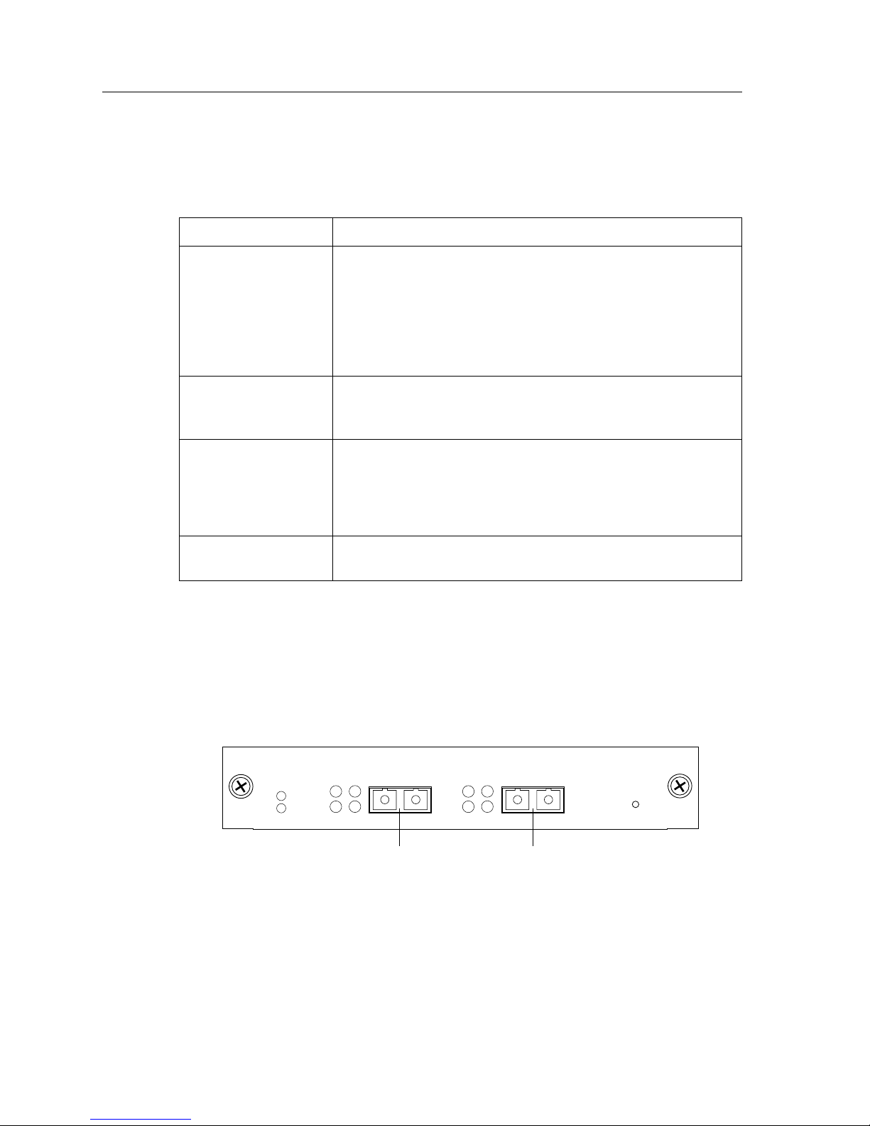
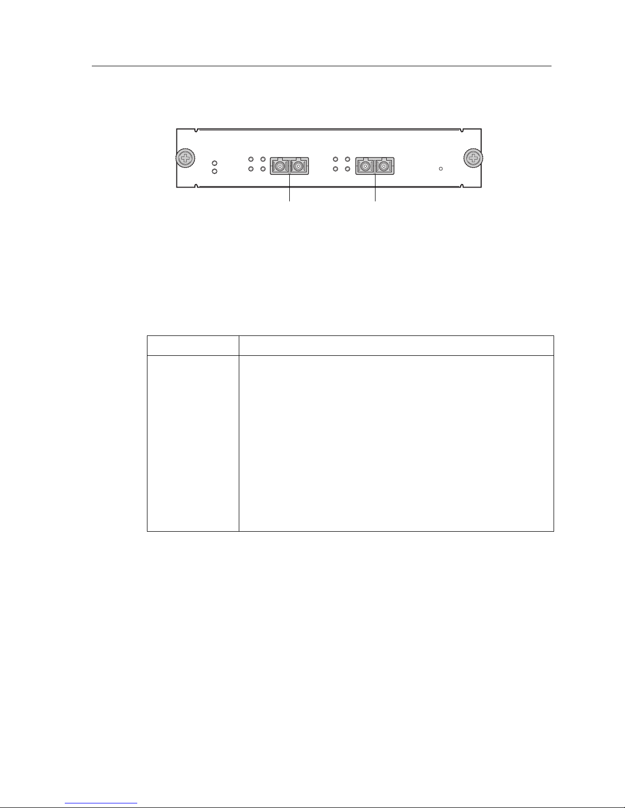
The 1000Base-SX line card and 1000Base-SX (T-Series) line cards contain two independent
Gigabit (1000 Mbps) Ethernet ports. The ports connect to multimode fiber (MMF) cables.
Figure 13 shows the front panel of the 1000Base-SX line card.
Offline
Online
Figure 13. Front panel of 1000Base-SX line card
sends or receives packets.
Tx Link
AN
Rx
Gigabit port Gigabit port
Tx Link
Rx
AN
1000BASE-SXSSR-GSX11-02
21
Hot
Swap
28 SSR 8000/8600 Getting Started Guide
Page 43
Chapter 1: Features Overview
Figure 14 shows the front panel of the 1000Base-SX (T-Series) line card.
1000BASE-SXSRR-GSX31-02
Offline
Online
Link
Tx
Rx
RxAN AN
21
LinkTx
Hot
Swap
Gigabit PortGigabit Port
Figure 14. Front panel of 1000Base-SX (T-Series) line card
Cabling and Connector Specifications
The following table lists the media specifications for the 1000Base-SX and 1000Base-SX (TSeries) line cards.
Port type Specification
1000Base-SX • 802.3z standard (also uses 802.3x for flow control)
• SC-style Media Interface Connector (MIC); either connection
pin in the MIC can be used for transmit or receive; see
“1000Base-SX Line Card and 100Base-FX Line Card” on page 74
for attaching cables
• 62.5 micron or 50 micron multimode fiber-optic cable
• Maximum 220 or 275 meters (722 or 902 feet) segment length for
62.5 micron fiber-optic cable, based on installed fiber bandwidth
• Maximum 500 or 550 meters (1640 or 1804 feet) segment length
for 50 micron fiber-optic cable, based on installed fiber
bandwidth
SSR 8000/8600 Getting Started Guide 29
Page 44

Chapter 1: Features Overview
LEDs
The 1000Base-SX and 1000Base-SX (T-Series) line cards use the following LEDs.
LED Description
Offline When lit, this amber LED on the left side of the line card
Online When lit, this green LED indicates that the line card is online
Per-port Link • Green – indicates that the port hardware detects a cable
indicates that the line card is offline (powered off) but is ready
for hot swap.
The Offline LED also is lit briefly during a reboot or reset of the
SSR but goes out as soon as the Control Module discovers the
line card.
and is ready to receive, process, and send packets if configured
to do so.
plugged into the port and a good link is established.
• Red (intermittent) – indicates that the port received an
error during operation.
• Red (solid) – indicates that the port hardware detects a
cable plugged into the port, however, a bad link is
established.
• Off – indicates that no link from the port exists.
30 SSR 8000/8600 Getting Started Guide
Page 45
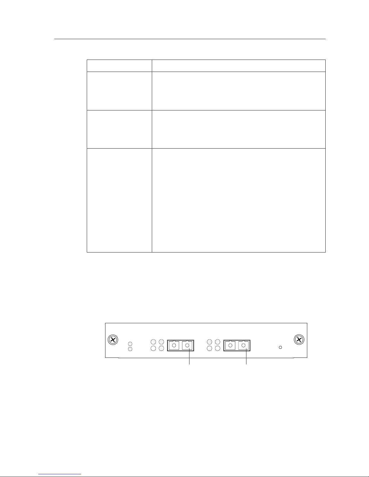
Chapter 1: Features Overview
LED Description
Per-port Rx • Green – indicates when the port’s transceiver receives
packets.
• Orange – indicates when the port’s transceiver receives
flow-control packets.
Per-port Tx • Green – indicates when the port’s transceiver transmits
packets.
• Orange – indicates when the port’s transceiver transmits
flow-control packets.
Per-port AN • Green – indicates that the line card has auto negotiated the
operating mode of the link between full-duplex and halfduplex.
• Orange (intermittent) – indicates that auto negotiation is in
process.
• Orange (solid) – indicates a problem with auto negotiation
configuration.
1000Base-LX Line Card
1000Base-LX (T-Series) Line Card
The 1000Base-LX and 1000Base-LX (T-Series) line cards provide the same features as the
1000Base-SX line card, but supports singlemode fiber (SMF) as well as MMF. Figure 15
shows the front panel of the 1000Base-LX line card.
Offline
Online
Figure 15. Front panel of 1000Base-LX line card
• Red – indicates an auto negotiation failure. This fault may
occur if the link partner does not support full duplex.
• Off – indicates that auto negotiation has been disabled or
the link is down.
1000BASE-LXSSR-GLX19-02
Tx Link
AN
Rx
Tx Link
AN
Rx
Gigabit port Gigabit port
21
Hot
Swap
SSR 8000/8600 Getting Started Guide 31
Page 46
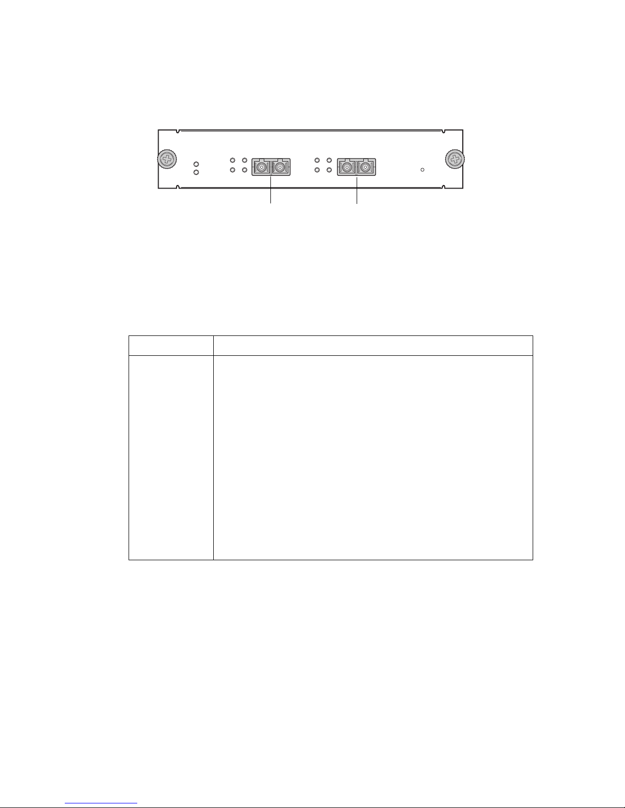
Figure 16 shows the front panel of the 1000Base-LX (T-Series) line card.
1000BASE-LXSRR-GLX39-02
Offline
Online
Link
Tx
Rx
RxAN AN
21
LinkTx
Hot
Swap
Gigabit Port
Gigabit Port
Figure 16. Front panel of 1000Base-LX (T-Series) line card
Cabling and Connector Specifications
The following table lists the media specifications for the 1000Base-LX and 1000Base-LX (TSeries) line cards.
Port type Specification
1000Base-LX • 802.3z standard (also uses 802.3x for flow control)
• SC-style Media Interface Connector (MIC); either connection pin
in the MIC can be used for transmit or receive; see “1000Base-LX
Line Card” on page 75 for attaching cables
• 62.5 micron or 50 micron multimode fiber-optic cable
• 9.5 micron singlemode fiber-optic cable
1
• Maximum 550 meters (1804 feet)
segment length for 62.5 micron
multimode fiber-optic cable
• Maximum 550 meters (1804 feet)
1
segment length for 50 micron
multimode fiber-optic cable
1. Mode Conditioning Patch cord required.
• Maximum 5 kilometers (229,659 feet) segment length for 10
micron singlemode fiber-optic cable
Page 47

Chapter 1: Features Overview
LEDs
The 1000Base-LX and 1000Base-LX (T-Series) line cards use the following LEDs.
LED Description
Offline When lit, this amber LED on the left side of the line card
indicates that the line card is offline (powered off) but is ready
for hot swap.
The Offline LED also is lit briefly during a reboot or reset of the
SSR but goes out as soon as the Control Module discovers the
line card.
Online When lit, this green LED indicates that the line card is online
and is ready to receive, process, and send packets if configured
to do so.
Per-port Link • Green – indicates that the port hardware detects a cable
plugged into the port and a good link is established
• Red (intermittent) – indicates that the port received an
error during operation
• Red (solid) – indicates that the port hardware detects a
cable plugged into the port, however, a bad link is
established
• Off – indicates that no link from the port exists
Per-port Rx • Green – indicates when the port’s transceiver receives
packets
• Orange – indicates when the port’s transceiver receives
flow-control packets
SSR 8000/8600 Getting Started Guide 33
Page 48
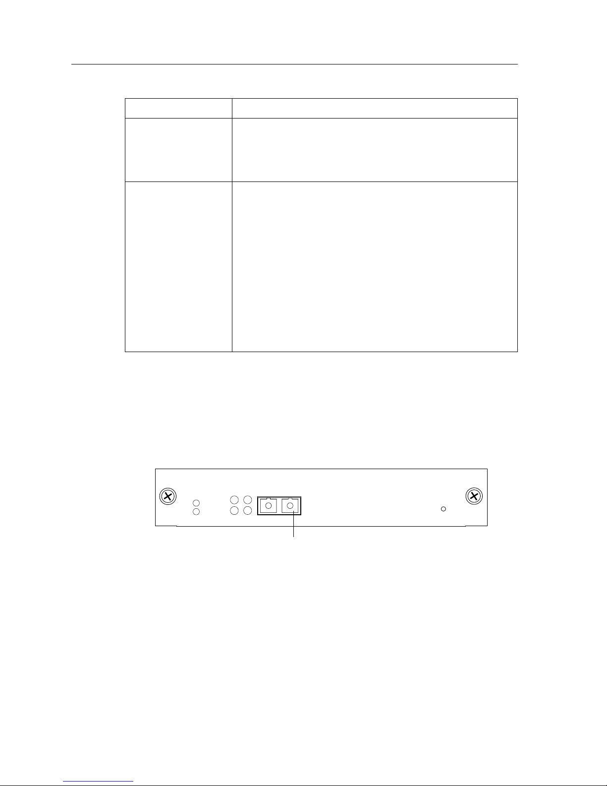
Chapter 1: Features Overview
LED Description
Per-port Tx • Green – indicates when the port’s transceiver transmits
Per-port AN • Green – indicates that the line card has auto negotiated the
packets
• Orange – indicates when the port’s transceiver transmits
flow-control packets
operating mode of the link between full-duplex and halfduplex
• Orange (intermittent) – indicates that auto negotiation is in
process
• Orange (solid) – indicates a problem with auto negotiation
configuration
• Red – indicates an auto negotiation failure. This fault may
occur if the link partner does not support full duplex
• Off – indicates that auto negotiation has been disabled or
the link is down
1000Base-LLX Line Card
1000Base-LLX (T-Series) Line Card
The 1000Base-LLX line card is similar to the 1000Base-LX line card, but extends the
transmission distance over singlemode fiber (SMF) to 70 kilometers for Gigabit Ethernet.
Figure 17 shows the front panel of the 1000Base-LLX line card.
Offline
Online
Figure 17. Front panel of 1000Base-LLX line card
Tx Link
AN
Rx
1000BASE-LLXSSR-GLX70-01
1
Hot
Swap
Gigabit port
34 SSR 8000/8600 Getting Started Guide
Page 49
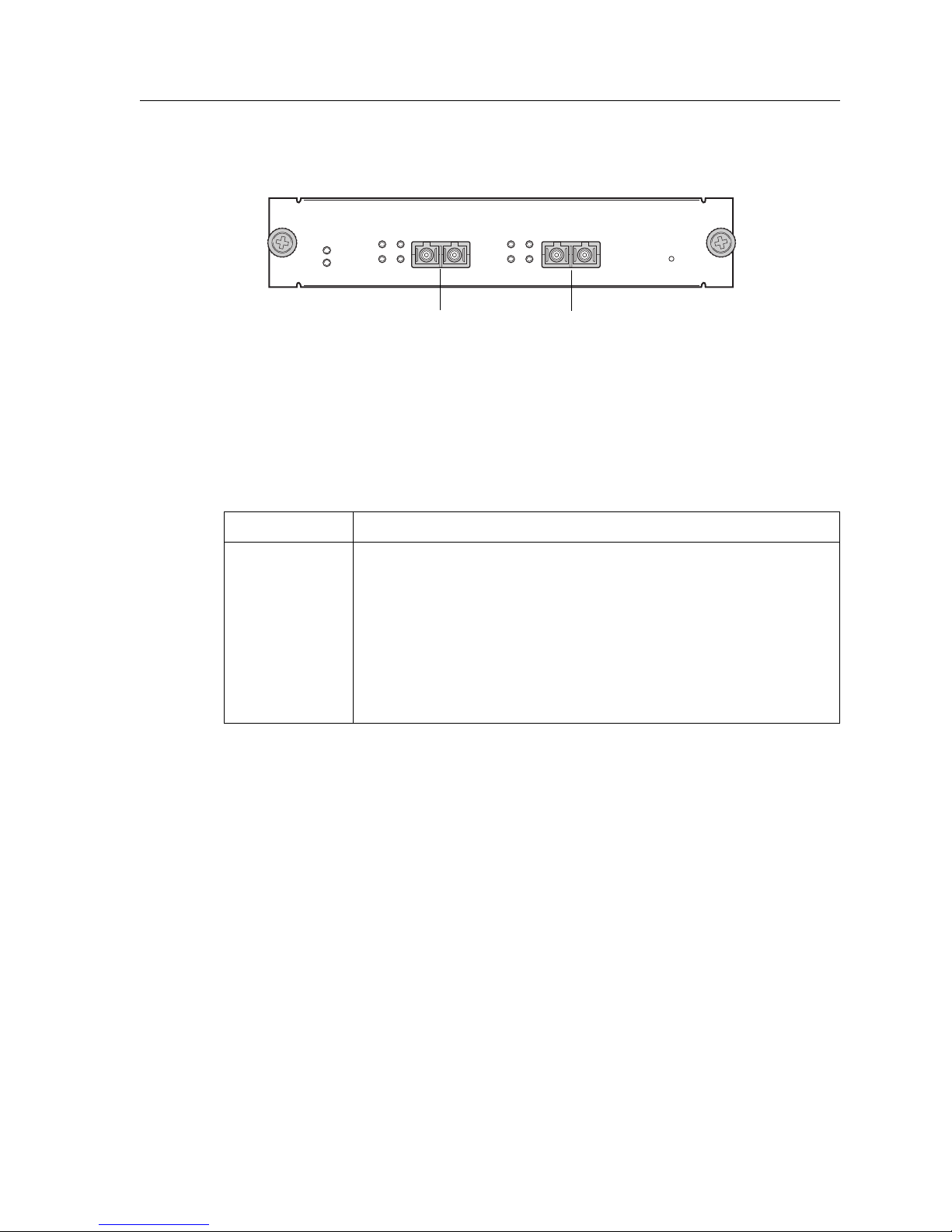
Chapter 1: Features Overview
Figure 17 shows the front panel of the 1000Base-LLX (T-Series) line card.
1000BASE-LLXSRR-GLH39-02
Offline
Online
Link
Tx
Rx
RxAN AN
21
LinkTx
Hot
Swap
Gigabit Port
Gigabit Port
Figure 18. Front panel of 1000Base-LLX (T-Series) line card
Cabling and Connector Specifications
The following table lists the media specifications for the 1000Base-LLX and 1000Base-LLX
(T-Series) line cards.
Port type Specification
1000Base-LX • 802.3z standard (also uses 802.3x for flow control)
• SC-style Media Interface Connector (MIC); either connection pin
in the MIC can be used for transmit or receive; see “1000Base-LX
Line Card” on page 75 for attaching cables
• 9.5 micron single-mode fiber-optic cable
• Maximum 70 kilometers (229,659 feet) segment length for 10
micron SMF fiber-optic cable
SSR 8000/8600 Getting Started Guide 35
Page 50

Chapter 1: Features Overview
LEDs
The 1000Base-LLX and 1000Base-LLX (T-Series) line cards use the following LEDs.
LED Description
Offline When lit, this amber LED on the left side of the line card that
Online When lit, this green LED indicates that the line card is online
Per-port Link • Green – indicates that the port hardware detects a cable
indicates that the line card is offline (powered off) but is ready
for hot swap.
The Offline LED also is lit briefly during a reboot or reset of the
SSR but goes out as soon as the Control Module discovers the
line card.
and is ready to receive, process, and send packets if configured
to do so.
plugged into the port and a good link is established
• Red (intermittent) – indicates that the port received an
error during operation
• Red (solid) – indicates that the port hardware detects a
cable plugged into the port, however, a bad link is
established
• Off – indicates that no link from the port exists
36 SSR 8000/8600 Getting Started Guide
Page 51
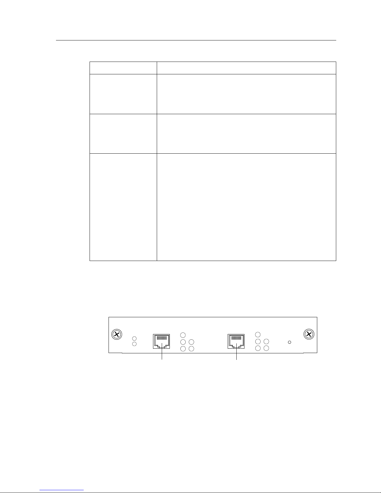
Chapter 1: Features Overview
LED Description
Per-port Rx • Green – indicates when the port’s transceiver receives
packets
• Orange – indicates when the port’s transceiver receives
flow-control packets
Per-port Tx • Green – indicates when the port’s transceiver transmits
packets
• Orange – indicates when the port’s transceiver transmits
flow-control packets
Per-port AN • Green – indicates that the line card has auto negotiated the
operating mode of the link between full-duplex and halfduplex
• Orange (intermittent) – indicates that auto negotiation is in
process
• Orange (solid) – indicates a problem with auto negotiation
configuration
1000Base-T Line Card (T-Series)
The 1000Base-T line card contains two independent Ethernet ports. Each port supports a
1000Base-T connection. Figure 19 shows the front panel of the 1000Base-T line card.
Offline
Online
• Red – indicates an auto negotiation failure. This fault may
occur if the link partner does not support full duplex
• Off – indicates that auto negotiation has been disabled or
the link is down
1000BASE-TSSR-GTX32-02
1
Link
Tx
Rx
1000Base-T port 1000Base-T port
Master
Quality
1
Link
Tx
Rx
Master
Quality
Hot
Swap
Figure 19. Front panel of 1000Base-T line card
SSR 8000/8600 Getting Started Guide 37
Page 52

Chapter 1: Features Overview
Cabling and Connector Specifications
The following table lists the media specifications for the 1000Base-T line card.
Port type Specification
1000Base-T • 802.3ab standard
LEDs
The 1000Base-T line card uses the following LEDs.
• RJ-45 connector wired as Media Data Interface Crossed (MDIX);
see “1000Base-T Line Card” on page 73 for pin assignments
• EIA Category 5 unshielded twisted pair cabling
• Maximum 100 meters (328 feet) segment length
LED Description
Offline When lit, this amber LED on the left side of the line card
indicates that the line card is offline (powered off) and is ready
for hot swap.
The Offline LED also is lit briefly during a reboot or reset of the
SSR and goes out as soon as the Control Module discovers and
properly initializes the line card.
Online When lit, this green LED indicates that the line card is online
and is ready to receive, process, and send packets if configured
to do so.
Per-port Link • Green – indicates that the port hardware detects a cable
plugged into the port and a good link is established
• Red (intermittent) – indicates that the port received an
error during operation
• Red (solid) – indicates that the port hardware detects a
cable plugged into the port, however, a bad link is
established
• Off – indicates that no link from the port exists
Per-port Rx • Green – indicates when the port’s transceiver receives
packets
38 SSR 8000/8600 Getting Started Guide
• Amber – indicates when the port’s transceiver receives
flow-control packets
Page 53

Chapter 1: Features Overview
LED Description
Per-port Tx • Green – indicates when the port’s transceiver transmits
packets
• Amber – indicates when the port’s transceiver transmits
flow-control packets
Master • Amber – indicates that the port is configured as the timing
master during auto-negotiation
• Off – indicates when the port is configured as the timing
slave during auto-negotiation
Quality • Off – indicates that either auto-negotiation is in progress or
the local receiver status is not OK
• Green – indicates that either auto-negotiation is complete
and is trying to establish a link or a link is established
• Fast Blink – indicates a low SNR and close to data error
• Slow Blink – indicates detection of receive bit error
ATM Line Card (T-Series)
The ATM line card actually houses various Physical Layer (PHY) interface cards in its two
available slots. ATM PHY cards provide the media-specific portion of an ATM interface to
support ATM connectivity across multiple platforms using different media types. The host
system provides the power, initialization, and control for the PHY card. The PHY card is
used with an ATM segmentation and reassembly (SAR) or cell-switching function.
See “Installing the ATM PHY Cards” on page 68 for installation instructions for the ATM
PHY cards into the ATM line card.
SSR 8000/8600 Getting Started Guide 39
Page 54
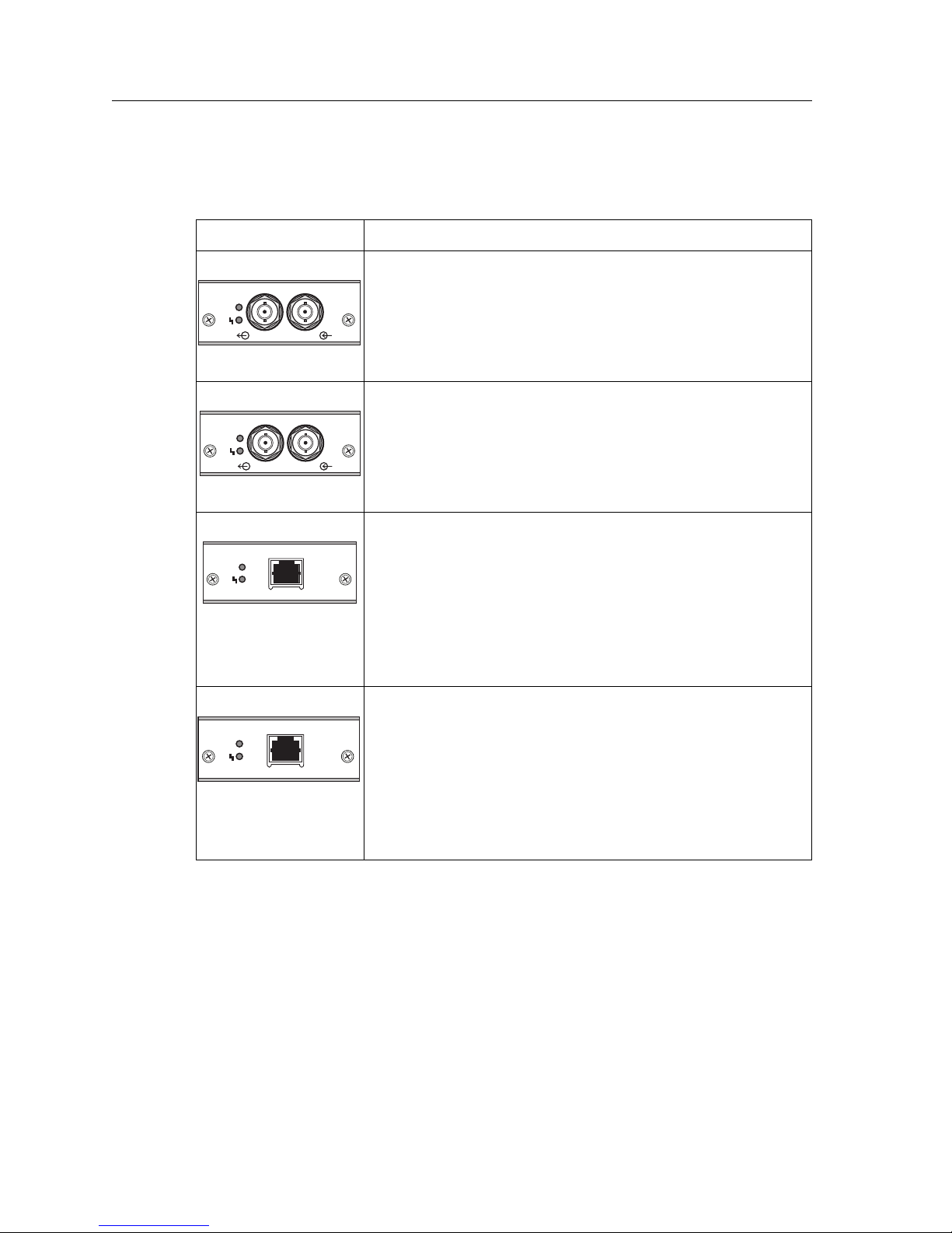
Chapter 1: Features Overview
The ATM line card has two available slots. Each slot accepts the following PHY interface
modules:
Port type Specification
APHY-67 • 1 DS-3/T-3 interface (BNC Coax); see “APHY-67 and
PHY
APHY-77 • 1 E-3 interface (BNC); see “APHY-67 and APHY-77” on
PHY
APHY-82 • 1 T-1 interface (UTP); see “APHY-82 and APHY-92” on
PHY
APHY-67
APHY-77
APHY-82
APHY-77” on page 76 for attaching cables
• 75 coaxial (RG-59B or equivalent) terminated with 75-ohm
BNC connectors
• Maximum of 450 ft (137 m) of cable
page 76 for attaching cables
• 75 coaxial (RG-59B or equivalent) terminated with 75-ohm
BNC connectors
• Maximum of 450 ft (137 m) of cable
page 76 for attaching cables
• ITU-T G.703 for a symmetrical pair
• 100 ohm symmetrical pair
• Maximum of 655 ft (200 m) of cable
• 0 through 6 dB loss at 200 m
APHY-92 • 1 E-1 interface (UTP); see “APHY-82 and APHY-92” on
PHY
APHY-92
page 76 for attaching cables
• ITU-T G.703 for a symmetrical pair
• 120 ohm symmetrical pair
• Maximum of 655 ft (200 m) of cable
• 0 through 6 dB loss at 200 m
40 SSR 8000/8600 Getting Started Guide
Page 55
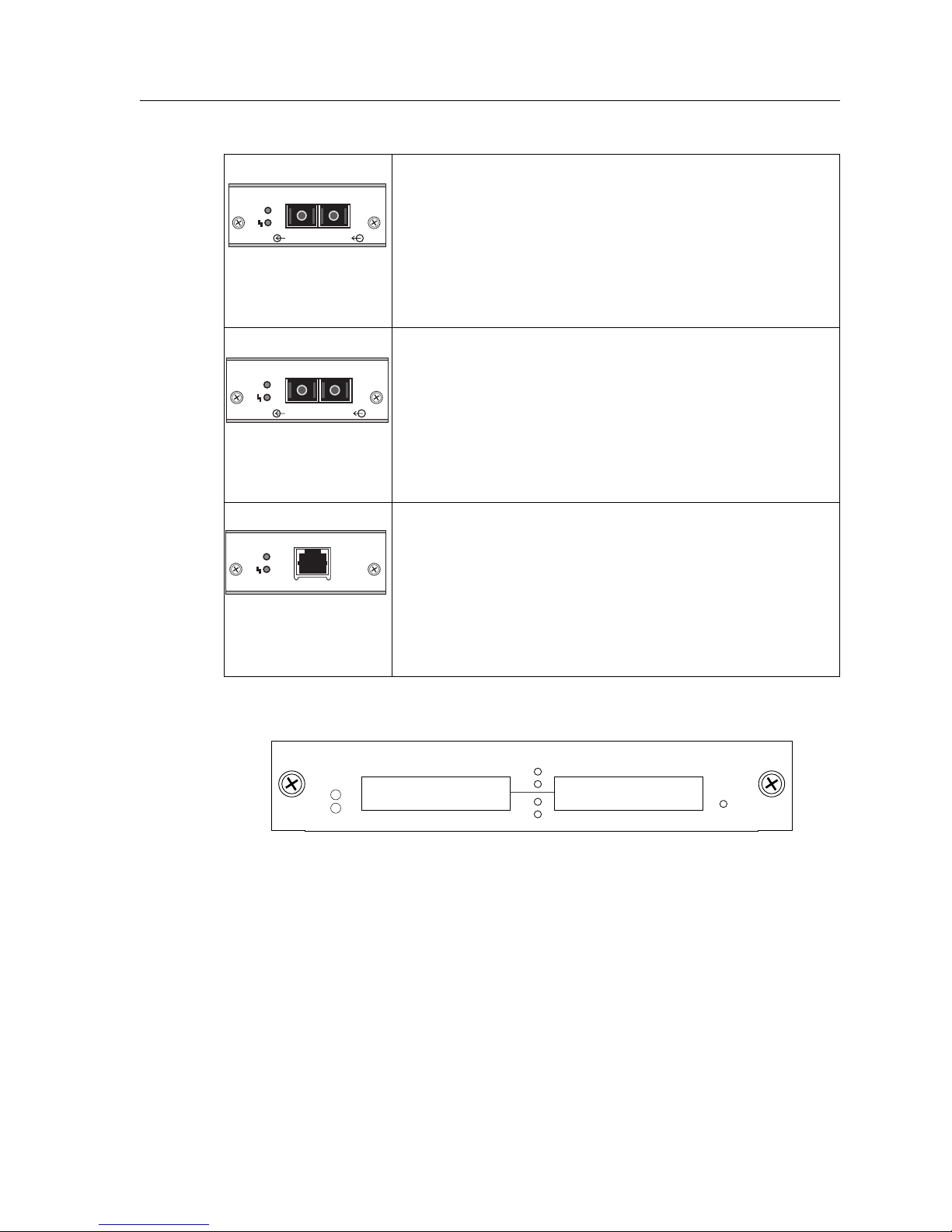
Chapter 1: Features Overview
APHY-21 • 1 OC-3c MMF interface (SC-style); see “APHY-21 and
PHY
APHY-21
APHY-29IR” on page 76 for attaching cables
• EIA/TIA 492-AAAA
• 62.5/125 µm
• Maximum of 2 kilometers of cable
• 0 through 9 dB loss at 1300 nm
APHY-29IR • 1 OC-3c SMF-IR interface (SC-style); see “APHY-21 and
PHY
APHY-29IR
APHY-29IR” on page 76 for attaching cables
• EIA/TIA 492-CAAA
•9/125 µm
• Maximum of 15 kilometers of cable
• 0 through 15 dB loss at 1300 nm
APHY-22 • 1 OC-3c interface (UTP); see “APHY-22” on page 76 for
PHY
APHY-22
attaching cables
• EIA/TIA 568B
•
295 ft (90 m) of Category 5 building cable
•
33 ft (10 m) of Category 5 patch cords
•
1 punchdown block (Category 5)
. Figure 26 shows the front panel of the ATM line card.
P2
Offline
Online
Tx
Rx
Tx
Rx
P1
Figure 20. Front panel of ATM line card
ATM MODULESSR-ATM29-02
Hot
Swap
SSR 8000/8600 Getting Started Guide 41
Page 56
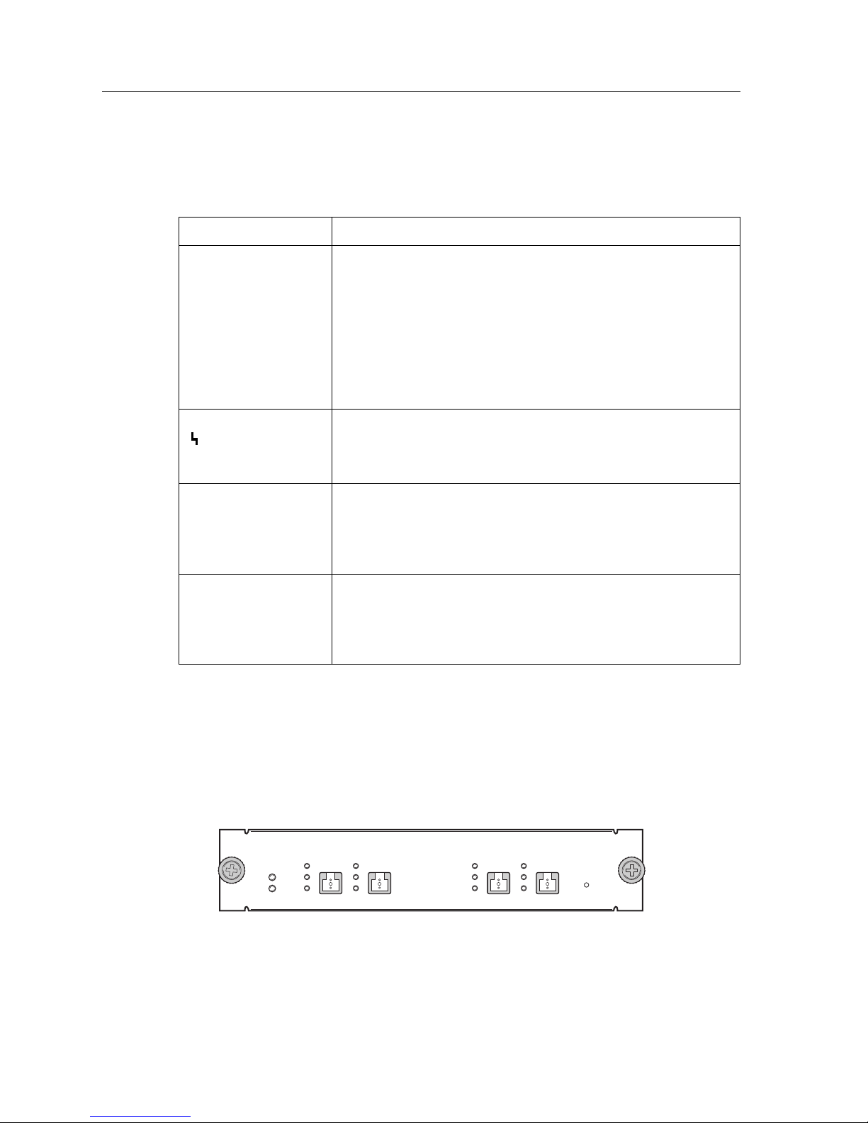
Chapter 1: Features Overview
LEDs
The ATM line card uses the following LEDs.
LED Description
PHY • Green – indicates that the PHY is operating properly and a
link is established
• Amber – indicates that the PHY is inactive due to media
errors
• Blinking Green – indicates that the PHY has been disabled
by management
• Off – indicates no connection
• Amber – indicates that the diagnostics have detected a fault
• Blinking Green – indicates that the PHY port has been
redirected elsewhere
Per-PHY Rx • Green – indicates when the PHY’s transceiver receives
Per-PHY Tx • Green – indicates when the PHY’s transceiver transmits
POS OC-3c MMF Line Card (T-Series)
POS OC-3c SMF Line Card (T-Series)
The Packet-over-SONET line card supports four OC-3c singlemode fiber (SMF) or
multimode fiber (MMF) connections using MT-RJ interfaces. Figure 21 shows the front
panel of the POS OC-3c MMF line card.
Link
Offline
Tx
Rx
Online
packets
• Amber – indicates when the PHY’s transceiver receives
flow-control packets
packets
• Amber – indicates when the PHY’s transceiver transmits
flow-control packets
POS OC-3 MMFSSR-POS21-04
Link
1
2
Tx
Rx
Link
Rx
Link
3
Tx
4
Tx
Rx
Hot
Swap
Figure 21. Front panel of POS OC-3c MMF line card
42 SSR 8000/8600 Getting Started Guide
Page 57
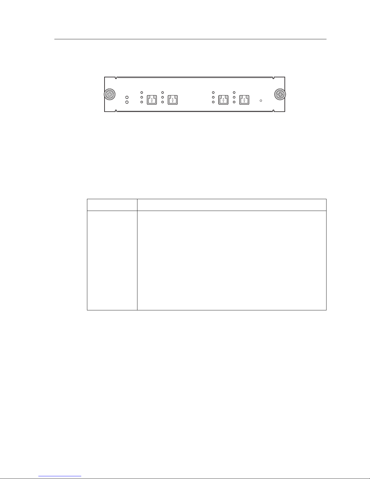
Chapter 1: Features Overview
Figure 22 shows the front panel of the POS OC-3c SMF line card.
POS OC-3 SMFSSR-POS29-04-IR
Offline
Online
Link
Tx
Rx
Link
1
2
Tx
Rx
Link
Tx
Rx
Link
3
4
Tx
Rx
Hot
Swap
Figure 22. Front panel of POS OC-3c SMF line card
Cabling and Connector Specifications
The following table lists the media specifications for the POS OC-3c MMF and POS OC-3c
SMF line cards.
Port type Specification
POS OC-3c • Bellcore GR253, ITU -T G.957, ITU-T G.958
• PPP over SONET/SDH (RFC 1619), PPP in HDLC framing (RFC
1662)
• MT-RJ-style connector; see “POS OC-3c Line Card” on page 77
for attaching cables
• 62.5 micron or 50 micron multimode MT-RJ fiber-optic cable
• 9.5 micron singlemode MT-RJ fiber-optic cable
• Maximum 2 kilometers for multimode fiber-optic cable
• Maximum 15 kilometers for singlemode fiber-optic cable
SSR 8000/8600 Getting Started Guide 43
Page 58

Chapter 1: Features Overview
LEDs
The POS OC-3c MMF and POS OC-3c MMF line cards use the following LEDs.
LED Description
Offline When lit, this amber LED on the left side of the line card
Online When lit, this green LED indicates that the line card is online
Per-port Link • Green – indicates that the port hardware detects a cable
indicates that the line card is offline (powered off) but is ready
for hot swap.
The Offline LED also is lit briefly during a reboot or reset of the
SSR but goes out as soon as the Control Module discovers the
line card.
and is ready to receive, process, and send packets if configured
to do so.
plugged into the port and a good link is established
• Red (intermittent) – indicates that the port received an
error during operation
• Red (solid) – indicates that the port hardware detects a
cable plugged into the port, however, a bad link is
established
• Off – indicates that no link from the port exists
Per-port Rx • Green – indicates when the port’s transceiver receives
packets
• Red – indicates when the port’s transceiver receives flowcontrol packets
Per-port Tx • Green – indicates when the port’s transceiver transmits
packets
• Red – indicates when the port’s transceiver transmits flowcontrol packets
44 SSR 8000/8600 Getting Started Guide
Page 59
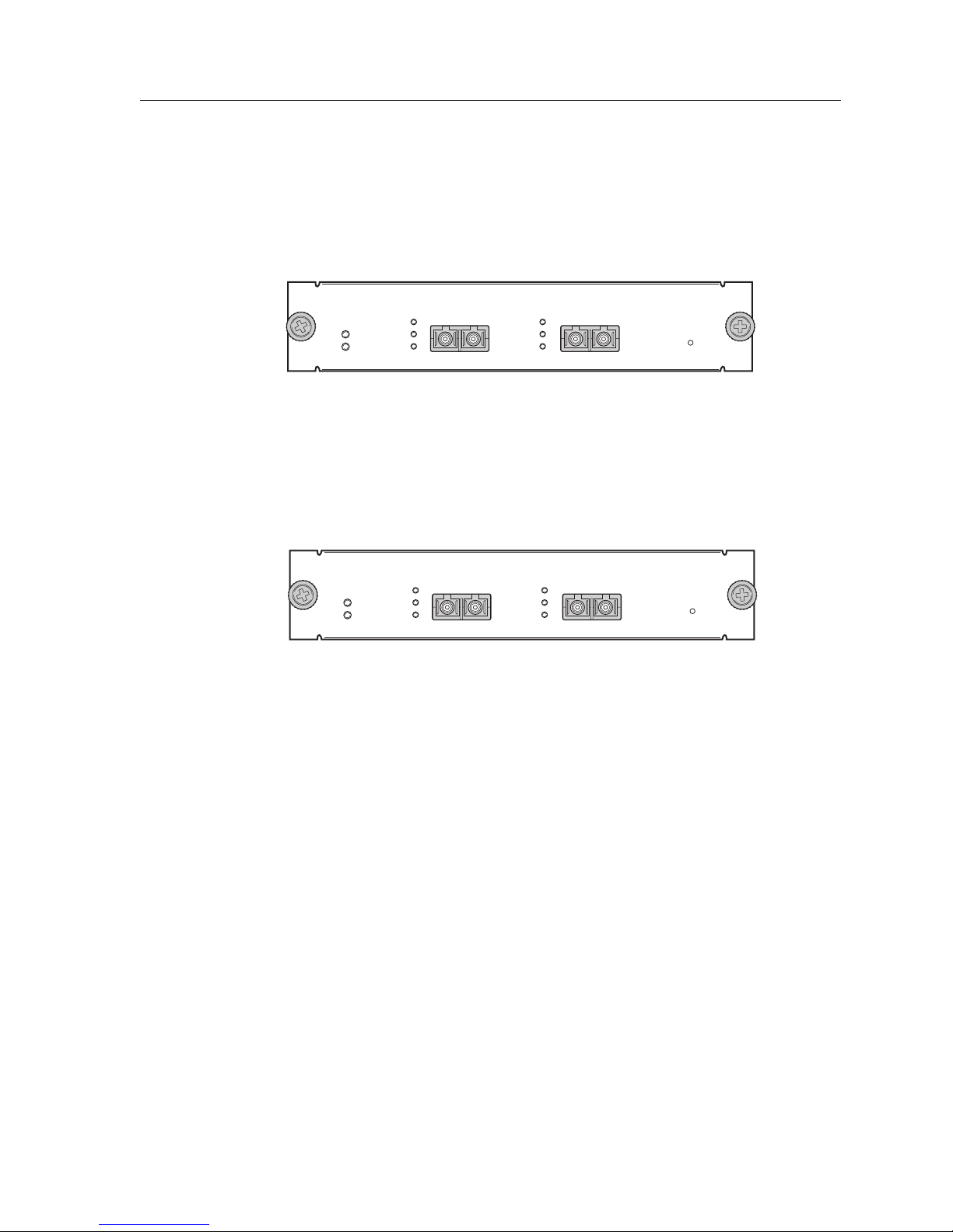
POS OC-12c MMF Line Card (T-Series)
POS OC-12c SMF Line Card (T-Series)
The Packet-over-SONET line card supports two OC-12c singlemode fiber (SMF) or
multimode fiber (MMF) SC-type connections. Figure 23 shows the front panel of the POS
OC-12c MMF line card.
Offline
Online
Link
Figure 23. Front panel of POS OC-12c MMF line card
Figure 24 shows the front panel of the POS OC-12c SMF line card.
Chapter 1: Features Overview
POS OC-12c MMFSSR-POS31-02
Link
Tx
Rx
Tx
Rx
21
Hot
Swap
POS OC-12c SMFSSR-POS39-02-IR
Offline
Online
Link
Tx
Rx
Link
Tx
Rx
21
Hot
Swap
Figure 24. Front panel of POS OC-12c SMF line card
SSR 8000/8600 Getting Started Guide 45
Page 60

Chapter 1: Features Overview
Cabling and Connector Specifications
The following table lists the media specifications for the POS OC-12c MMF and POS OC12c SMF line cards.
Port type Specification
POS OC-12c • Bellcore GR253, ITU -T G.957, ITU-T G.958
• PPP over SONET/SDH (RFC 1619), PPP in HDLC framing (RFC
1662)
• SC-style Media Interface Connector (MIC); either connection pin
in the MIC can be used for transmit or receive; see “POS OC-12c
Line Card” on page 77 for attaching cables
• 62.5 micron or 50 micron multimode fiber-optic cable
• 9.5 micron singlemode fiber-optic cable
• Maximum 1 kilometers for multimode fiber-optic cable
• Maximum 13 kilometers for singlemode fiber-optic cable
LEDs
The POS OC-3c MMF and POS OC-3c MMF line cards use the following LEDs.
LED Description
Offline When lit, this amber LED on the left side of the line card
indicates that the line card is offline (powered off) but is ready
for hot swap.
The Offline LED also is lit briefly during a reboot or reset of the
SSR but goes out as soon as the Control Module discovers the
line card.
Online When lit, this green LED indicates that the line card is online
and is ready to receive, process, and send packets if configured
to do so.
46 SSR 8000/8600 Getting Started Guide
Page 61
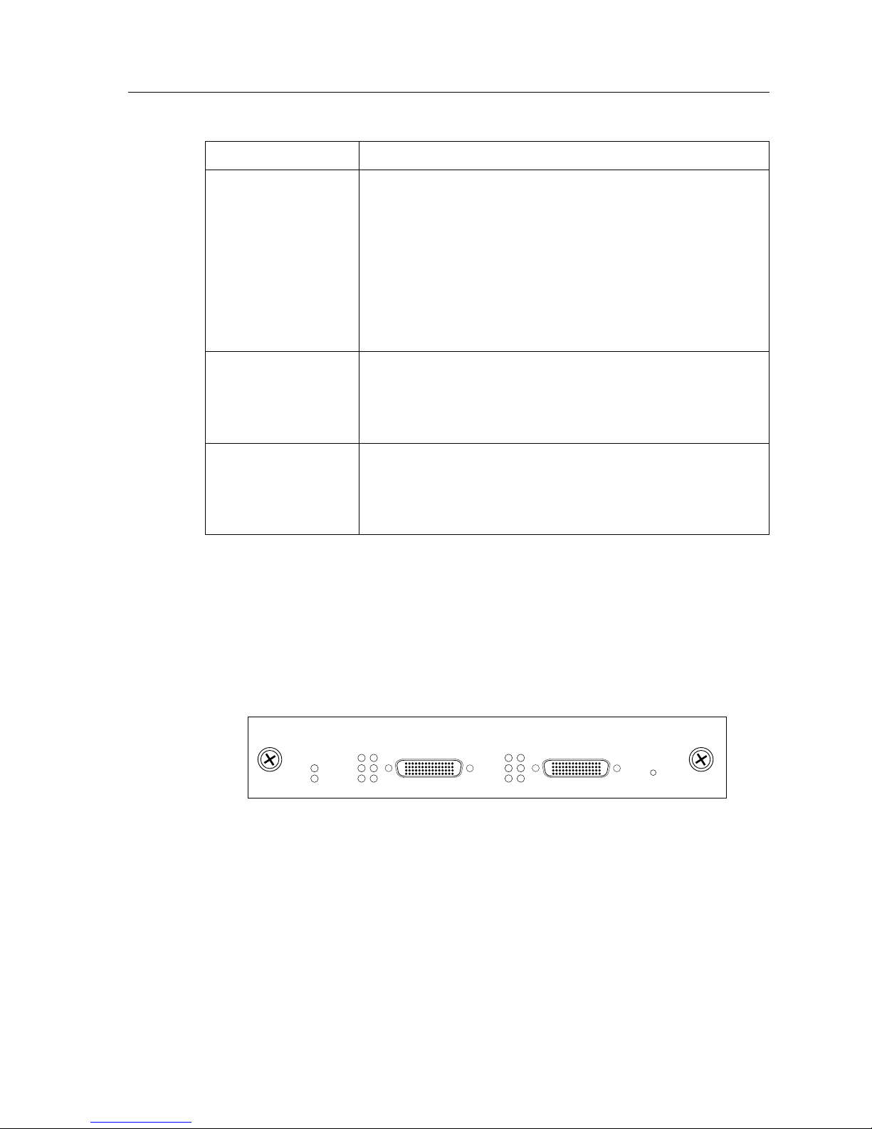
Chapter 1: Features Overview
LED Description
Per-port Link • Green – indicates that the port hardware detects a cable
plugged into the port and a good link is established
• Red (intermittent) – indicates that the port received an
error during operation
• Red (solid) – indicates that the port hardware detects a
cable plugged into the port, however, a bad link is
established
• Off – indicates that no link from the port exists
Per-port Rx • Green – indicates when the port’s transceiver receives
packets
• Red – indicates when the port’s transceiver receives flowcontrol packets
Per-port Tx • Green – indicates when the port’s transceiver transmits
packets
• Red – indicates when the port’s transceiver transmits flowcontrol packets
Quad Serial – C and Quad Serial – CE Line Cards
The Quad Serial – C and Quad Serial – CE line cards each contain two dual-serial WAN
ports (two serial ports located on one high density connector). In addition, the Quad
Serial – C line card includes compression, and the Quad Serial – CE line card includes
compression and encryption, for each WAN port. Figure 25 shows the front panel of the
Quad Serial – CE WAN line card.
Offline
Online
12
Link
Rx
Tx
1,2
Figure 25. Front panel of Quad Serial – CE WAN line card
Quad Serial - CSSR-SERC-04
34
Link
Rx
Tx
3,4
Hot
Swap
SSR 8000/8600 Getting Started Guide 47
Page 62
Chapter 1: Features Overview
Cabling and Connector Specifications
The following table lists the media specifications for the Quad Serial – C/CE line cards.
Port Type Specification
Dual serial • V.35, X.21, EIA530, EIA530A, or RS449
• LFH-60 high density connector; see “Quad Serial – C and Quad
Serial – CE Line Cards” on page 77 for pin assignments
• Recommended 3 meters (10 feet) segment length for standard
WAN line card-to-CSU/DSU data port.
1. Connector cables for WAN line cards may be ordered from Cabletron Systems. For detailed
information, including part numbers, see “Quad Serial – C and Quad Serial – CE Line Cards” on page
77.
1
LEDs
The Quad Serial – C/CE line cards use the following LEDs.
LED Description
Offline When lit, this amber LED on the left side of the line card indicates
that the line card is offline (powered off) but is ready for hot swap.
The Offline LED also is lit briefly during a reboot or reset of the SSR
but goes out as soon as the Control Module discovers the line card.
Online When lit, this green LED indicates that the line card is online and is
ready to receive, process, and send packets if configured to do so.
Per-port Link Indicates that the line card detects a cable plugged into the port and
a good link is established.
Per-port Rx Indicates when the port’s transceiver receives data.
Per-port Tx Indicates when the port’s transceiver transmits data.
48 SSR 8000/8600 Getting Started Guide
Page 63
Dual HSSI Line Card
The Dual HSSI line card contains two 50-pin High Speed Serial Interface (HSSI) ports.
Figure 26 shows the front panel of the Dual HSSI WAN line card.
Chapter 1: Features Overview
Dual HSSISSR-HSSI-02
Offline
Online
Link
Rx
Tx
Link
Rx
Tx
Hot
Swap
Figure 26. Front panel of Dual HSSI WAN line card
Cabling and Connector Specifications
The following table lists the media specifications for the Dual HSSI line card.
Port Type Specification
HSSI • HSSI rev 2.11
• 50-pin High Speed Serial Interface (HSSI) connector; see “Dual
HSSI Line Card” on page 79 for pin assignments
• Recommended 3 meters (10 feet) segment length for standard WAN
line card-to-CSU/DSU data port.
1. Connector cables for WAN line cards may be ordered from Cabletron Systems. For detailed
information, including part numbers, see “Dual HSSI Line Card” on page 79.
1
LEDs
The Dual HSSI line card uses the following LEDs.
LED Description
Offline When lit, this amber LED on the left side of the line card indicates
that the line card is offline (powered off) but is ready for hot swap.
The Offline LED also is lit briefly during a reboot or reset of the SSR
but goes out as soon as the Control Module discovers the line card.
Online When lit, this green LED indicates that the line card is online and is
ready to receive, process, and send packets if configured to do so.
SSR 8000/8600 Getting Started Guide 49
Page 64
Chapter 1: Features Overview
LED Description
Link Indicates that the line card detects a cable plugged into the port and
Rx Indicates when the port’s transceiver receives data.
Tx Indicates when the port’s transceiver transmits data.
a good link is established.
50 SSR 8000/8600 Getting Started Guide
Page 65

Hardware Installation
This chapter provides hardware installation information and procedures in the following
sections:
• Safety considerations
• Installing the hardware
If the hardware is already installed and you are ready to install the software and perform
basic system configuration, see Chapter 3, “Software Installation and Setup” on page 81.
Safety Considerations
Chapter 2
Read the following safety warnings and product cautions to avoid personal injury or
product damage.
Preventing Injury
Cautions
working with the SmartSwitch Router (SSR) hardware.
• To avoid back strain, be careful when lifting the chassis out of the shipping box.
• Never attempt to rack mount the SSR chassis unaided. Ask an assistant to help you
• Never operate the SSR with exposed power-supply bays or module slots. You can leave
• Never operate the SSR if the chassis becomes wet or the area where the chassis is
SSR 8000/8600 Getting Started Guide 51
: Observe the following safety warnings to prevent accidental injury when
hold the chassis.
the PCMCIA slots exposed but make sure you do not place any tools or body parts in
the PCMCIA slot.
installed is wet.
Page 66
Chapter 2: Hardware Installation
Preventing Equipment Damage
Observe the precautions listed in this section to prevent accidental damage to the SSR
components.
Cautions
: To prevent accidental product damage, observe the following precautions:
• Always use proper electrostatic discharge (ESD) gear when handling the Control
Module, backplane, line cards or other internal parts of the chassis.
• Make sure you allow adequate room for air flow around the chassis.
• If you plan to install the chassis in an equipment rack, it is recommended that you
install a support tray under the chassis, especially for chassis that are completely filled
(no empty Control Module, power supply, or line card slots).
Hardware Specifications
The following table lists the physical and environmental specifications for the SSR 8000
and SSR 8600.
SSR 8000 SSR 8600
Dimensions Inches: 8.27” x 17.25” x 12.25”
Centimeters: 22.23cm x 43.82cm
x 31.12cm
Inches: 8.27” x 17.25” x 19.25”
Centimeters: 22.23cm x 43.82cm
x 48.9 cm
Weight Pounds: 24
Kilograms: 10.8
Power 100-125 VAC, 5A maximum;
200-240 VAC, 3A maximum
Operating
Fahrenheit: 41
o
F to 104oF
Pounds: 47
Kilograms: 21.2
100-125 VAC, 10A maximum;
200-240 VAC, 6A maximum
o
Fahrenheit: 41
F to 104oF
temperature
Centigrade: 5
52 SSR 8000/8600 Getting Started Guide
o
C to 40oC
Centigrade: 5
o
C to 40oC
Page 67

Installing the Hardware
This section describes how to perform the following tasks:
• Check the shipping box to ensure that all the parts arrived
• Install the chassis (on a tabletop or in an equipment rack)
• Install the Control Module
• Install a memory upgrade
• Install the switching fabric module (SSR 8600 only)
• Install line cards
• Install the power supply (either AC or DC)
• Attach console management cables
• Attach port cables
Chapter 2: Hardware Installation
Verifying Your Shipment
Before you begin installing your SSR, check your shipment to ensure that everything you
ordered arrived securely.
Caution
Open the shipping box(es) and verify that you received the following equipment:
• An SSR 8000 or SSR 8600 chassis containing a backplane, fan module, and a console
• An SSR 8000 or SSR 8600 power supply.
• One country-specific power cable per power supply.
• One Control Module.
• One Switching Fabric Module (SSR 8600 only).
• An SSR Media Kit containing:
: To avoid back strain, be careful when lifting the chassis out of the shipping box.
cable. The console cable is used for connecting a terminal to the Control Module DB-9
port.
– A CD-ROM containing user documentation and the CoreWatch software
– One PCMCIA flash card containing the SSR system software
–One copy of the SmartSwitch Router Getting Started Guide (the book you are reading
now)
– Release Notes
SSR 8000/8600 Getting Started Guide 53
Page 68

Chapter 2: Hardware Installation
Depending on your order, your shipment may also contain some or all of the following:
• Redundant power supply, if you ordered one.
• Redundant Control Module, if you ordered one.
• Redundant Switching Fabric Module, if you ordered one (SSR 8600 only).
• The line cards you ordered.
Installing the Chassis
Cabletron recommends that only qualified personnel conduct installation of any SSR
chassis.
This section contains procedures for the following types of installation:
• Tabletop Installation
• Rack mount Installation
Tabletop Installation
You can install the SSR on a tabletop.
1. Select a table that is stable (not wobbly) and is not in an area subject to frequent foot
traffic. Remember that you will be attaching numerous cables to the chassis.
2. Place the SSR on the table, allowing at least 3 inches (7.62 centimeters) of room above
and behind the unit for air flow to the cooling fans.
Rack Mount Installation
You can install the SSR in a standard 19” equipment rack. The SSR chassis is equipped
with front-mounting brackets. Figure 27 shows an example of how to install an SSR 8600
chassis in an equipment rack.
54 SSR 8000/8600 Getting Started Guide
Page 69
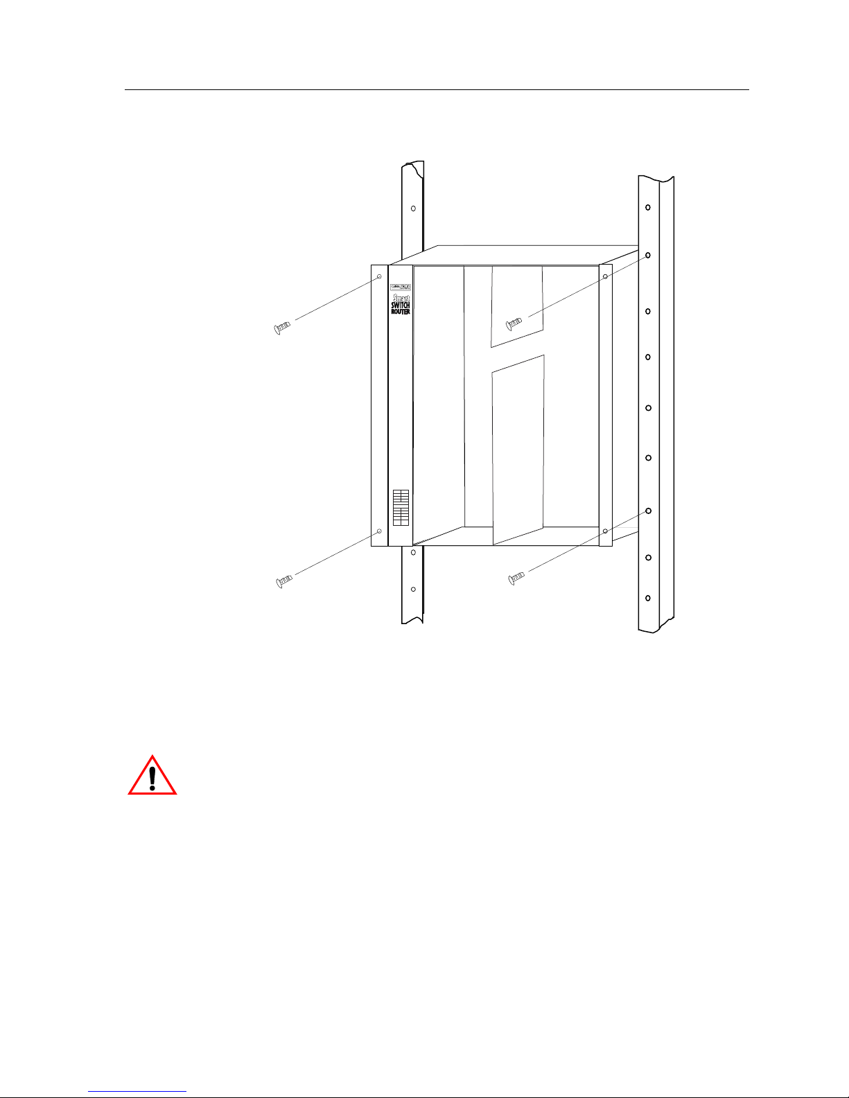
Chapter 2: Hardware Installation
SSR-16
Figure 27. Installing the SSR 8600 chassis in an equipment rack
Note: Never attempt to rack mount the SSR chassis unaided. Ask an assistant to help
you hold the chassis.
Caution
: To make lifting and holding the chassis easier, install the chassis before you install
line cards or redundant Control Modules and power supplies.
To install the SSR chassis in an equipment rack, use the following procedure. You need a
#2 Phillips-head screwdriver to perform this procedure.
1. If the front-mounting brackets are already installed on the SSR chassis, go to Step 2.
If not, do the following:
a. Align one of the mounting brackets over the corresponding holes in the side of
the chassis. The mounting bracket is correctly positioned when the side with two
open mounting holes is flush with the front of the chassis.
SSR 8000/8600 Getting Started Guide 55
Page 70
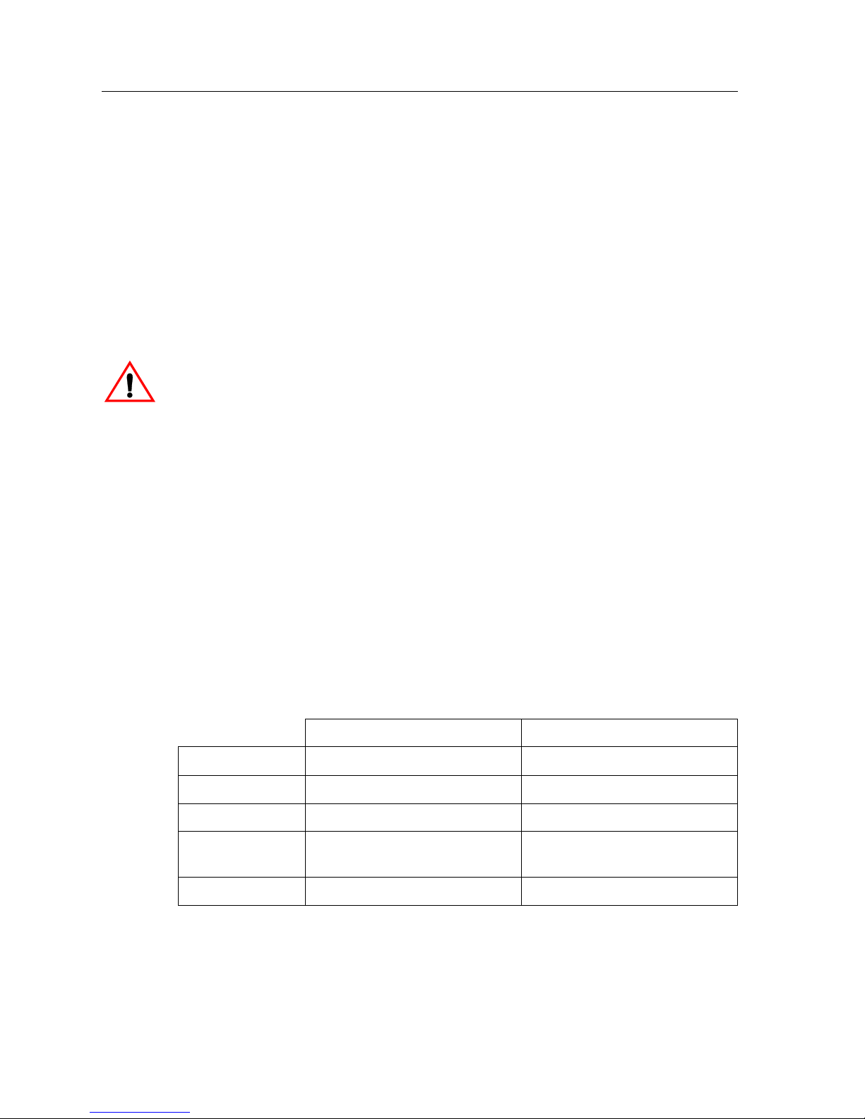
Chapter 2: Hardware Installation
b. Use the #2 Phillips-head screwdriver and two of the supplied Phillips-head
screws to attach the mounting bracket to the chassis.
c. Attach the other mounting bracket.
2. Along with an assistant, lift the chassis into place in the mounting rack.
3. While your assistant holds the chassis in place, use the #2 Phillips-head screwdriver
and four #2 Phillips-head screws to attach the mounting brackets to the mounting
rack.
Note: Make sure there are at least 3 inches (7.62 centimeters) of room above and behind
the unit for air flow to the cooling fans.
Caution
: Make sure the screws are tight before your assistant releases the chassis. If you
accidentally leave the screws loose, the chassis can slip and fall, possibly becoming
damaged.
Installing an AC Power Supply
The primary AC power supply is shipped separately from the SSR chassis. To install or
replace the primary AC power supply or if you want to install a redundant power supply,
use the following procedure. You will need a #2 Phillips-head screwdriver to perform this
procedure.
Note: Use a single-phase grounded power source located within 6 feet (1.89 meters) of
the installation site.
AC Power Supply Specifications
The following table lists the physical specifications for the SSR’s AC Power Supplies.
SSR 8000 SSR 8600
Dimensions 11.00" (L) x 7.70" (W) x 2.55" (H) 12.15" (L) x 7.70" (W) x 5.05" (H)
Weight 6.5 lbs. (2.95 kg) 12.0 lbs. (5.45 kg)
Power Output 300 W 600 W
Voltage Range 100-125V, 5A
Frequency 50-60 Hz 50-60 Hz
56 SSR 8000/8600 Getting Started Guide
200-240V, 3A
100-125V, 10A
200-240V, 6A
Page 71
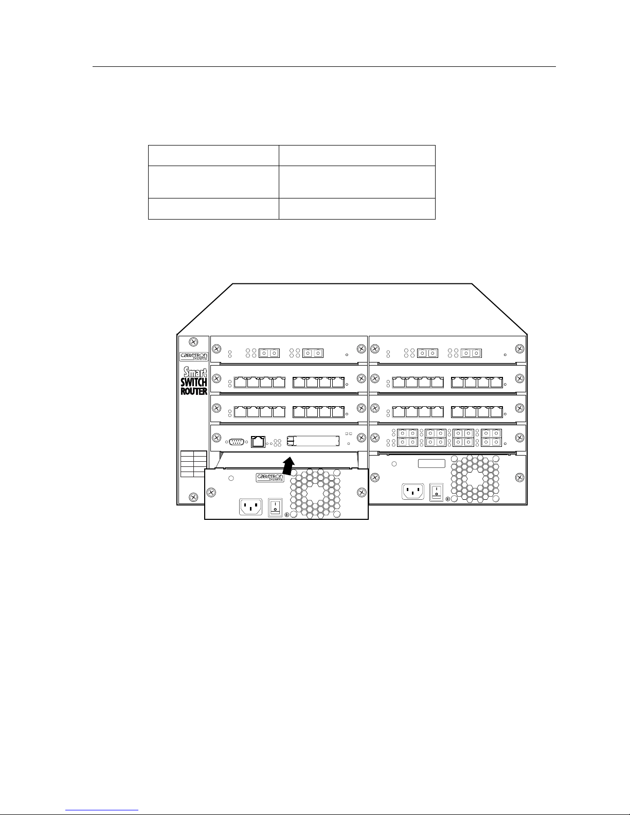
Chapter 2: Hardware Installation
The following table lists the environmental specifications for the SSR’s AC Power
Supplies
Operating Temperature +5° to +40°C (41° to 104°F)
Non-operating
-30° to +73°C (-22° to 164°F)
temperature
Operating Humidity 15% to 90% (non-condensing)
Figure 28 shows an example of how to install an AC power supply. The procedure
following the figure describes how to do this.
SSR-8
PWR
100-125~5A
200-240~3A
50-60 Hz
SSR-PS-8
Figure 28. Installing an AC Power Supply
AC Power Supply Installation Procedure
To install an AC power supply:
1. Ensure that the AC power supply is not powered on.
2. If a cover plate is installed over the power supply slot, use the #2 Phillips-head
screwdriver to remove it. If you are replacing an AC power supply, unplug the power
cable from the supply you are replacing, loosen the captive screws on the power
supply’s front panel, then pull the supply out of the chassis.
SSR 8000/8600 Getting Started Guide 57
Page 72
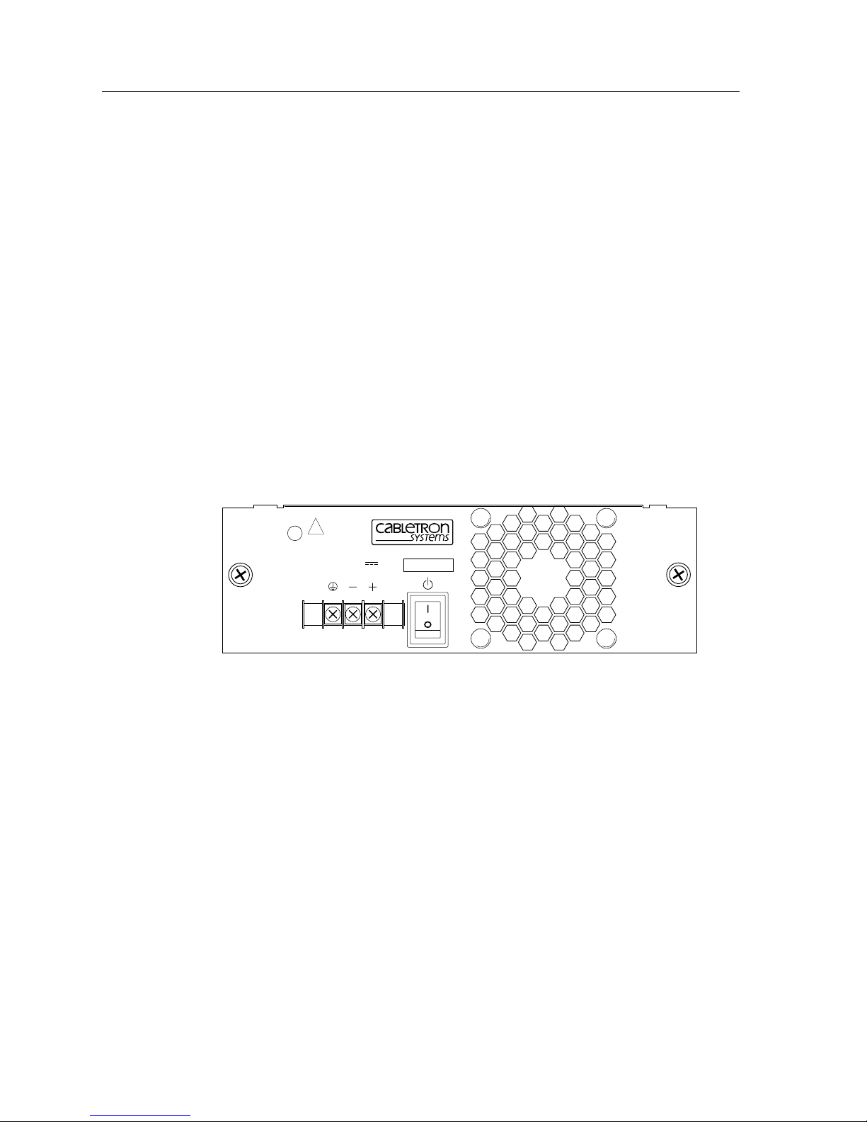
Chapter 2: Hardware Installation
3. Slide the AC power supply all the way into the slot, firmly but gently pressing to
ensure that the pins on the back of the power supply are completely seated in the
backplane.
4. Use the #2 Phillips-head screwdriver to tighten the captive screws on each side of the
power supply to secure it to the chassis.
5. Attach the power cable to the AC power supply.
Installing a DC Power Supply
The SSR DC power supply delivers 3.3, 5, and 12 volts DC to the SSR’s Control Module(s),
fan modules, and other components. A single DC power supply provides enough current
to operate a fully-configured chassis.
SSR 8000 DC Power Supply
Figure 29 shows the front view of an SSR 8000 DC power supply.
To be installed in a restricted
access area in accordance
with the NEC or authority
!
having jurisdiction.
See manual for installation
instructions.
PWR
48/60V
14A MAX
SSR-PS-8-DC
SN
Figure 29. Front View of an SSR 8000 DC Power Supply
The SSR 8000 DC power supply has a three-terminal wiring block on the front panel,
consisting of a positive(+) terminal, negative(-) terminal and a safety ground. The DC
supply is designed to be powered by a 48 Volt DC source. 12 to 14 gauge wire should be
used to connect the 48 Volt source to the SSR 8000 DC power supply. 12 to 14 gauge wire
should also be used for the safety ground.
58 SSR 8000/8600 Getting Started Guide
Page 73
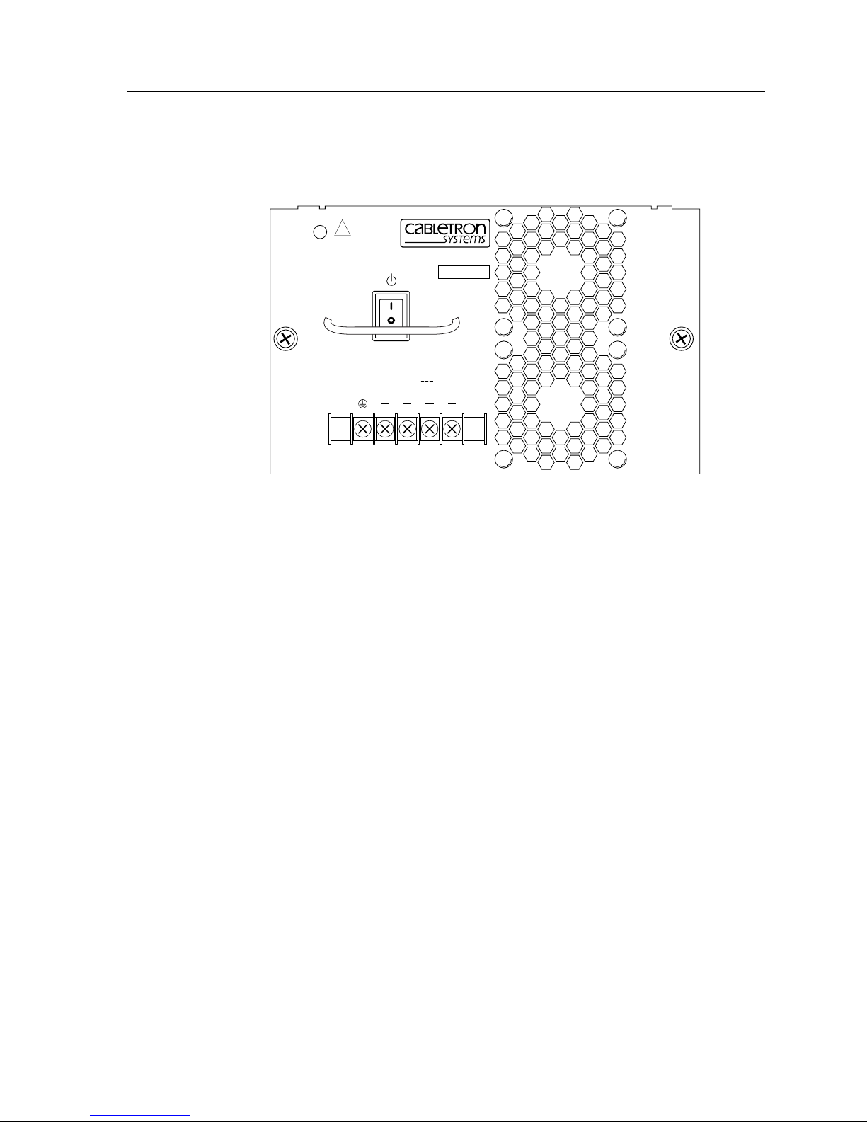
SSR 8600 DC Power Supply
Figure 30 shows the front view of an SSR 8600 DC Power Supply.
PWR
To be installed in a restricted
access area in accordance
with the NEC or authority
!
having jurisdiction.
See manual for installation
instructions.
SSR-PS-16-DC
SN
48/60V
27A MAX
Chapter 2: Hardware Installation
Figure 30. Front View of an SSR 8600 DC Power Supply
The SSR 8600 DC power supply has a five-terminal wiring block on the front panel. The
wiring block contains two positive(+) terminals, two negative(-) terminals, and a safety
ground. The DC supply is designed to be powered by a 48 Volt DC source.
Internally, the SSR 8600 DC power supply consists of two separate power supplies. Each
of these internal power supplies must be energized to produce sufficient power for the
SSR 8600 to operate. Each internal power supply is connected to source power through a
pair of positive (+) and negative (-) wiring lugs on the wiring block. Figure 31 shows the
internal relationship of the wiring lugs of the SSR 8600 DC power supply.
Note: For the SSR 8600 to work properly, both positive (+) terminals and both negative
(-) terminals of the SSR 8600 DC power supply MUST be connected to the DC
source.
SSR 8000/8600 Getting Started Guide 59
Page 74
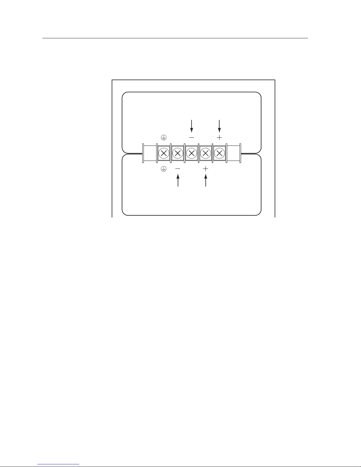
Chapter 2: Hardware Installation
SSR-16 DC Power Supply
Internal Power Supply One
These lugs supply power
to Power Supply One
These lugs supply power
to Power Supply Two
Internal Power Supply Two
Figure 31. Relationship of wiring lugs on SSR 8600 DC power supply
Because of the SSR 8600 DC supply current requirements, each pole of the 48 Volt DC
source should use 6 gauge wire. Each 6 gauge wire can be divided into two 12 gauge wires
by using a conductive splitter-block. This creates two 12 gauge wires carrying positive (+)
current and two 12 gauge wires carrying negative current. In turn, both 12 gauge positive
(+) wires and both 12 gauge negative (-) wires are connected to the SSR 8600 DC power
supply wiring block. See Figure 32.
60 SSR 8000/8600 Getting Started Guide
Page 75
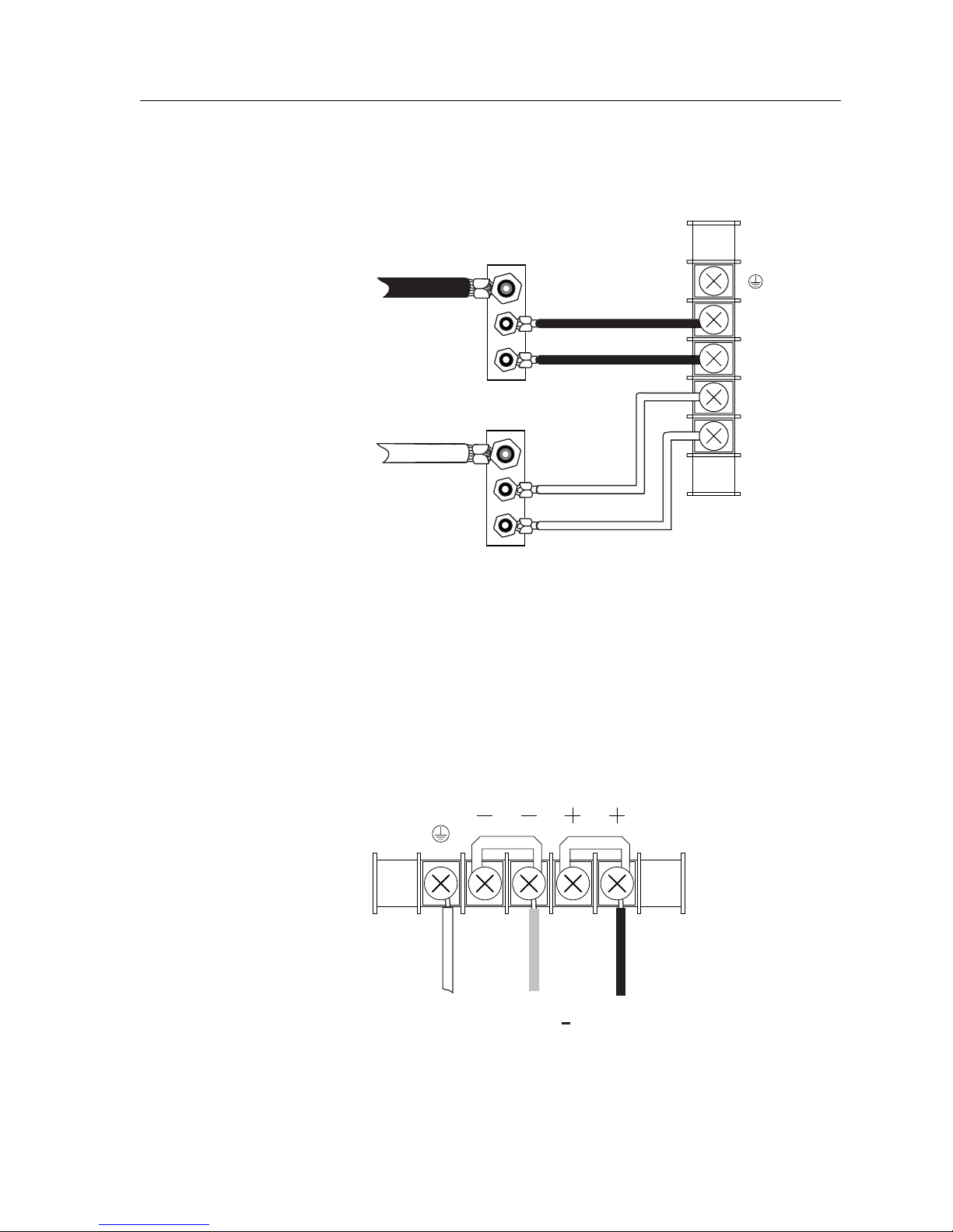
From - 48 Volt
source
6 Gauge Wire
Conductive
Splitter Block
Chapter 2: Hardware Installation
SSR-16
Wiring Lugs
12 Gauge Wire
-
12 Gauge Wire
+
+
From + 48 Volt
Source
6 Gauge Wire
Conductive
Splitter Block
12 Gauge Wire
12 Gauge Wire
Figure 32. Splitting each source wire to two 12 gauge wires
An alternate method of wiring the SSR 8600 power supply is to use a single set of wires (+
and -) from the DC source, and then tie the SSR 8600’s wiring lugs together: + to + and - to
-. See Figure 33.
Both positive (+) and both
negative (-) lugs are tied
together
SSR 8000/8600 Getting Started Guide 61
To True
Ground
From Power
Source
From Power
Source +
Figure 33. Tying SSR 8600 DC supply lugs together
Page 76
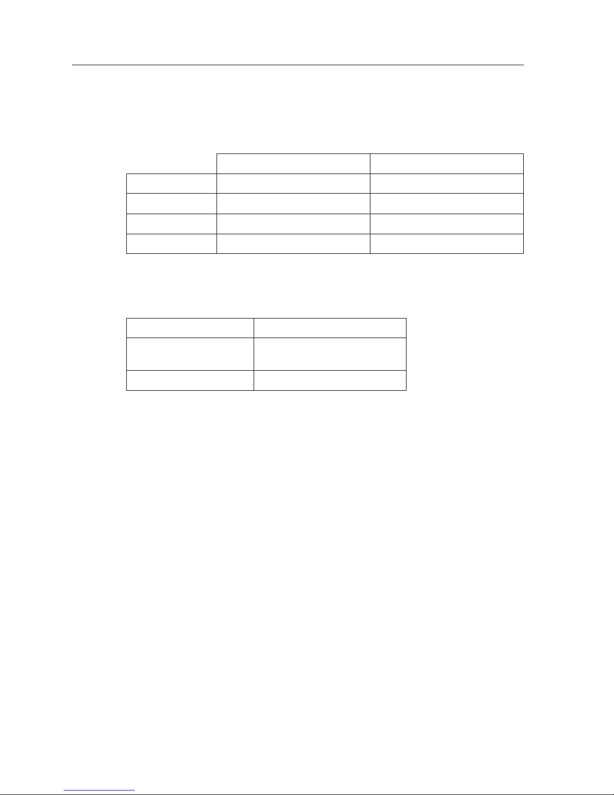
Chapter 2: Hardware Installation
DC Power Supply Specifications
The following table lists the physical specifications for the SSR’s DC Power Supplies.
Dimensions 11.00" (L) x 7.70" (W) x 2.55" (H) 12.15" (L) x 7.70" (W) x 5.05" (H)
Weight 6.5 lbs. (2.95 kg) 12.0 lbs. (5.45 kg)
Power Output 300 W 600 W
Voltage Range 36-72V, 14 A @ 48 V nominal 36-72V, 27 A @ 48 V nominal
The following table lists the environmental specifications for the SSR’s DC Power
Supplies
Operating Temperature +5° to +40°C (41° to 104°F)
SSR 8000 SSR 8600
Non-operating
temperature
Operating Humidity 15% to 90% (non-condensing)
DC Power Connections
• Connect to a reliably grounded SELV source.
• The Branch circuit overcurrent protection must be rated a maximum of 15A.
• Use 12 AWG or 14 AWG solid copper conductors only.
• A readily accessible disconnect device that is suitably approved and rated shall be
incorporated in the field wiring.
DC Power Supply Installation Procedure
To install a DC power supply on the SSR 8000 or SSR 8600:
1. Ensure that the DC power supply is not powered on.
2. If a cover plate is installed over the DC power supply slot, use a #2 Phillips-head
screwdriver to remove it. If you are replacing a power supply, unplug the power cable
from the supply you are replacing, loosen the captive screws on the power supply’s
front panel, then pull the supply out of the chassis.
-30° to +73°C (-22° to 164°F)
3. Slide the DC power supply all the way into the slot, firmly but gently pressing to
ensure that the pins on the back of the power supply are completely seated in the
backplane.
62 SSR 8000/8600 Getting Started Guide
Page 77
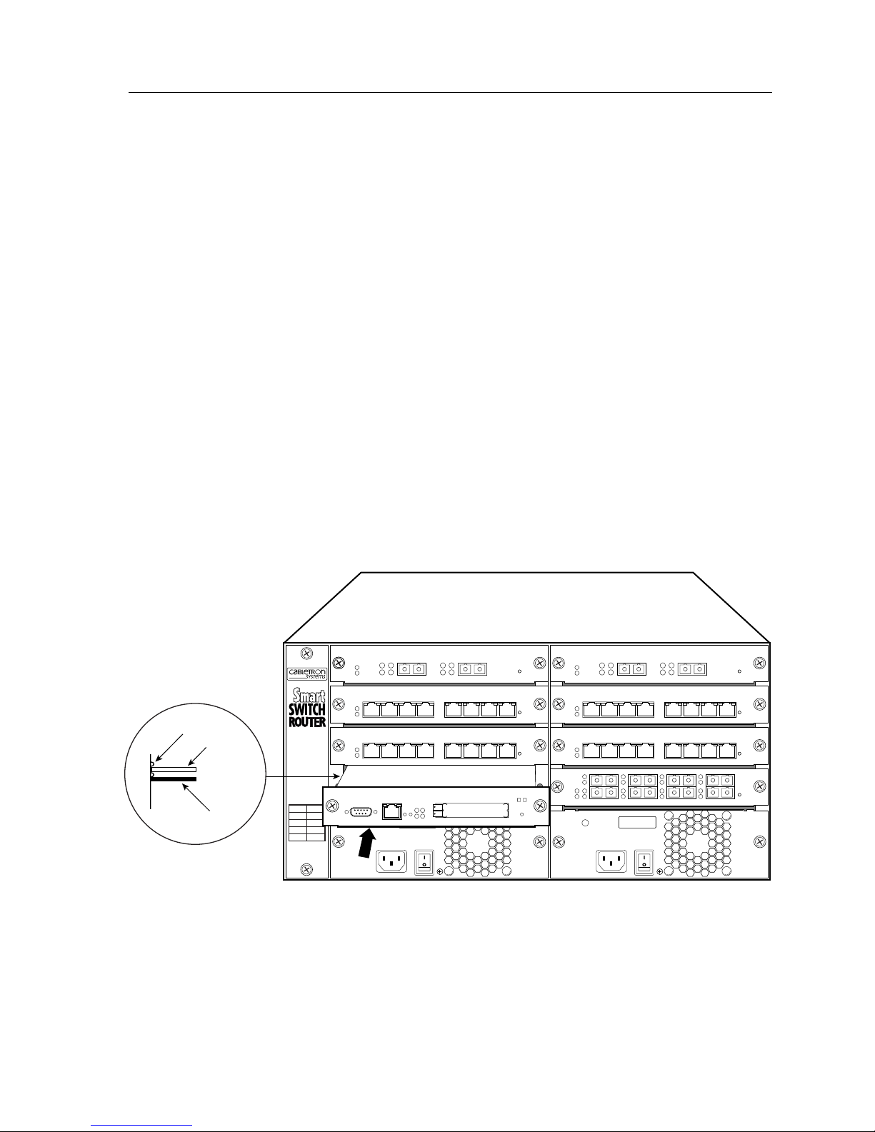
4. Use a #2 Phillips-head screwdriver to tighten the captive screws on each side of the
DC power supply to secure it to the chassis.
5. Attach wires to the terminal blocks on the front of the unit. To attach a wire, loosen the
terminal screw, insert the exposed end of the wire, and tighten the terminal screw.
6. Connect the safety ground wire to a reliable earth ground.
7. Connect the DC input wiring to a DC power source. See Figure 32 and Figure 33 for a
diagram of the wiring connections between the SSR and a DC power source.
Installing the Control Module
The primary Control Module always resides in the CM slot. If you need to replace the
primary Control Module in the CM slot, or you want to install a redundant Control
Module in slot CM/1, use the following procedure. You will need a #2 Phillips-head
screwdriver to perform this procedure.
The primary Control Module must be installed in slot CM. The redundant Control
Module must be installed in slot CM/1. (See “Chassis” on page 12 for information about
the chassis slots.)
Chapter 2: Hardware Installation
Figure 34 shows an example of how to install a Control Module. The procedure following
the figure describes how to do this.
Card Guides
Circuit Card
SSR-CM-2 CONTROL MODULE
10/100 Mgmt
Console
Metal Plate
SSR-8
Figure 34. Installing a Control Module
To install the Control Module:
SSR 8000/8600 Getting Started Guide 63
Page 78
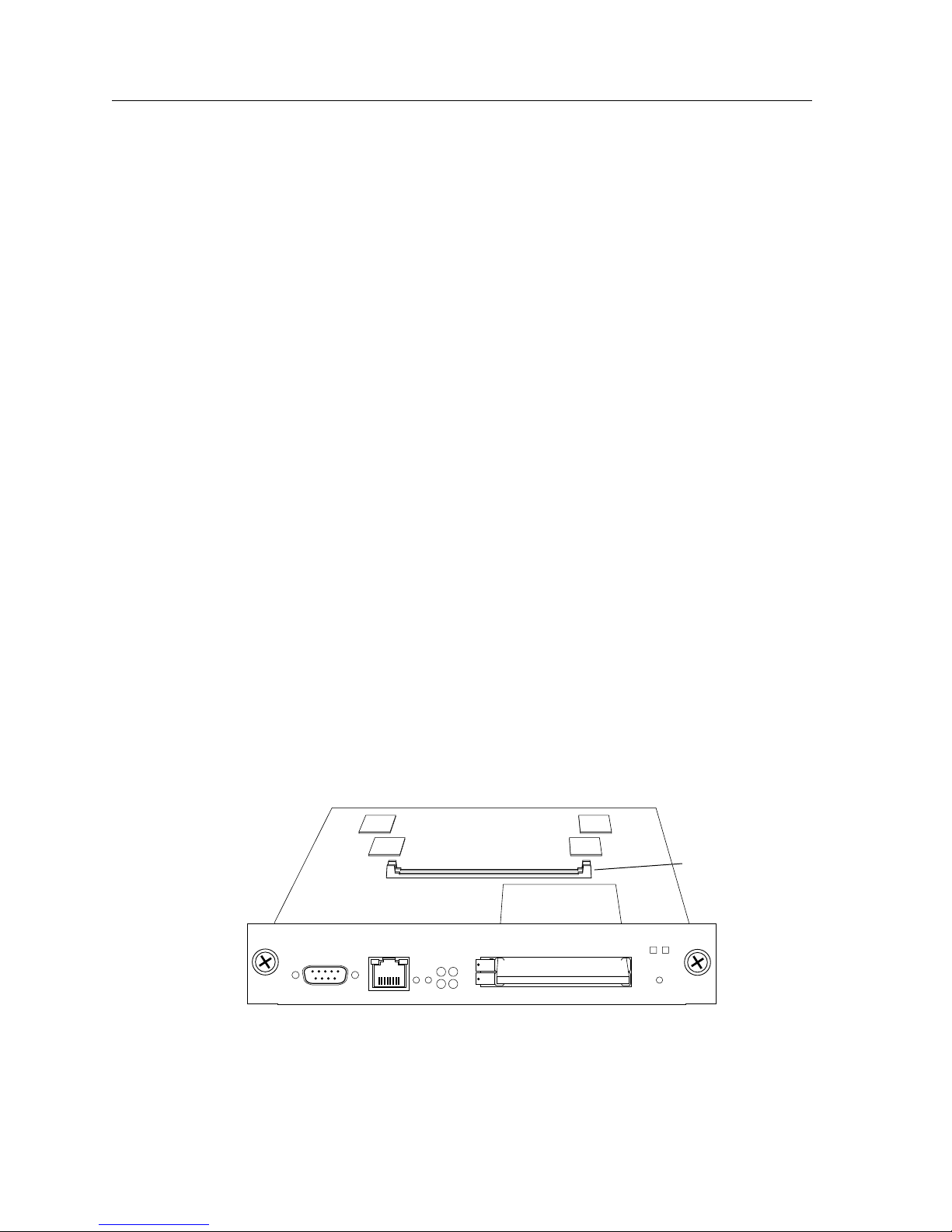
Chapter 2: Hardware Installation
1. If a cover plate is installed over the Control Module slot (slot or CM/1 only), use the
#2 Phillips-head screwdriver to remove it.
2. Slide the Control Module all the way into the slot, firmly but gently pressing to ensure
that the pins on the back of the Control Module are completely seated in the
backplane.
Note: Make sure the circuit card (and not the metal plate) is between the card
guides, as shown in Figure 34. Check both the upper and lower tracks.
3. Use the #2 Phillips-head screwdriver to tighten the captive screws on each side of the
Control Module to secure it to the chassis.
4. When you are ready to attach the management cables to the Control Module, use the
procedures in “Attaching the Console Management Cables” on page 70.
Installing a Memory Upgrade
The Control Module is shipped from the factory with a minimum of 64MB memory (in a
64MB DIMM). Memory upgrade kits can be obtained from Cabletron Systems to increase
memory to 128 MB or 256 MB. Use the following procedure to upgrade the memory to
128MB (one 128MB DIMM) or 256MB (two 128MB DIMMs). You will need a #2 Phillipshead screwdriver to perform this procedure.
1. If the chassis contains an active, redundant Control Module, go to Step 2. Otherwise, if
the SSR chassis does not contain a redundant Control Module, power down the
chassis by switching the power switch on the power supply to the Off position.
2. Use a #2 Phillips-head screwdriver to loosen the captive screws on the Control
Module.
3. Pull the Control Module out of the chassis and place the module on an ESD-safe work
area.
4. Remove the DIMMS from the memory slots. Figure 35 shows the locations of the
DIMM slots.
Memory slots
SSR-CM2 CONTROL MODULE
Console
10/100 Mgmt
Figure 35. Location of DIMM slots
64 SSR 8000/8600 Getting Started Guide
Page 79

Chapter 2: Hardware Installation
5. Store the DIMMs in an ESD-safe bag or other container and put them in a safe place.
6. Insert the new DIMMs in the slots, making sure that the contacts are fully inserted
downward into the connector slot.
7. Install the upgraded Control Module back into the chassis. (See “Installing the
Control Module” on page 63.)
Installing the Switching Fabric Module (SSR 8600 only)
On the SSR 8600, the switching fabric module is shipped separately from the SSR chassis.
To install or replace the primary switching fabric module, or if you want to install a
redundant switching fabric module, use the following procedure. You will need a #2
Phillips-head screwdriver to perform this procedure
The primary switching fabric module must be installed in slot Fabric 1. The redundant
switching fabric module must be installed in slot Fabric 2.
SSR 8000/8600 Getting Started Guide 65
Page 80
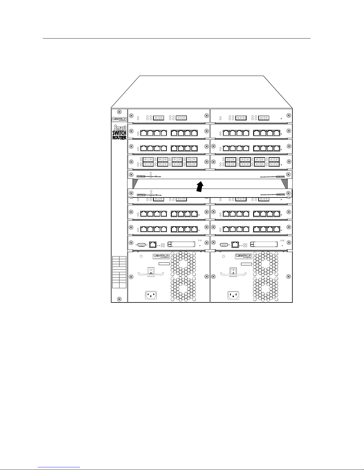
Chapter 2: Hardware Installation
Figure 36 shows an example of how to install a switching fabric module. The procedure
following the figure describes how to do this.
14 15
12
13
10
11
8
9
Fabric 2
Fabric 1
6
7
4
5
3
2
CM/1
CM
PS2PS1
SSR-16
1000BASE-LXSSR-GLX19-02
21
10/100BASE-TXSSR-HTX12-08
87654321
10/100BASE-TXSSR-HTX12-08
87654321
100BASE-FXSSR-HFX11-08
3
4
TO REMOVE POWER TO
UNIT DISCONNECT ALL
POWER SUPPLY CORDS
100-125V~ 10A
200-240V~ 6A
50/60 Hz
SSR-PS-16
SN
21
SSR-SF-16
SSR-SF-16
SSR-CM-2 CONTROL MODULE
PWR
87
5
6
1000BASE-LXSSR-GLX19-02 SSR-GSX11-02
21
10/100BASE-TXSSR-HTX12-08
87654321
10/100BASE-TXSSR-HTX12-08
87654321
1000BASE-SXSSR-GSX11-02
21
10/100BASE-TXSSR-HTX12-08
87654321
10/100BASE-TXSSR-HTX12-08
87654321
Switching Fabric
Switching Fabric
1000BASE-SX
21
10/100BASE-TXSSR-HTX12-08
10/100BASE-TXSSR-HTX12-08
100BASE-FXSSR-HFX11-08
87
6
87654321
87654321
3
4
5
21
SSR-CM-2 CONTROL MODULE
PWR
SSR-PS-16
SN
TO REMOVE POWER TO
UNIT DISCONNECT ALL
POWER SUPPLY CORDS
100-125V~ 10A
200-240V~ 6A
50/60 Hz
Figure 36. Installing a switching fabric module on the SSR 8600
To install a switching fabric module:
1. If a cover plate is installed over the switching fabric module slot (slot Fabric 1 or
Fabric 2), use the #2 Phillips-head screwdriver to remove the cover plate.
2. Slide the switching fabric module all the way into the slot, firmly but gently pressing
to ensure that the pins on the back of the module are completely seated in the
backplane.
Note: Make sure the circuit card (and not the metal plate) is between the card
guides, as shown in Figure 34 on page 63. Check both the upper and lower
tracks.
66 SSR 8000/8600 Getting Started Guide
Page 81
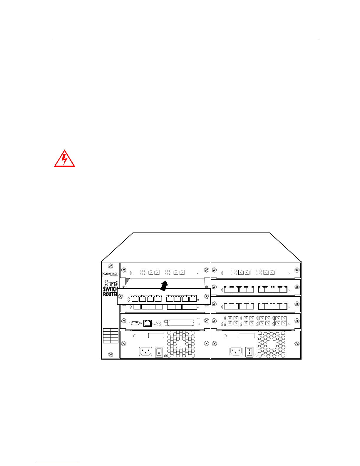
3. Lock down the left and right metal tabs to secure the switching fabric module to the
chassis.
4. Use the #2 Phillips-head screwdriver to tighten the captive screws on each side of the
switching fabric to secure the switching fabric to the chassis.
Installing the Line Cards
You can install line cards in slots 1 – 7 (or 1 – 15 on the SSR 8600). If you also plan to install
a redundant Control Module, you can install line cards in slots 2 – 7 (2– 15 on the SSR
8600). You will need a #2 Phillips-head screwdriver to perform this procedure.
Chapter 2: Hardware Installation
Warning
: The SSR supports hot swapping. This means you can remove and insert line
cards while the SSR is operating. However, you should not insert tools or body parts
inside the chassis while it is powered on. Doing so can cause electrical shock or equipment
damage.
For more information on hot swapping, see “Hot Swapping Line Cards and Control
Modules” in the SmartSwitch Router User Reference Manual.
Figure 37 shows an example of how to install a line card. The procedure following the
figure describes how to do this.
10/100BASE-TXSSR-HTX12-08
87654321
SSR-8
SSR 8000/8600 Getting Started Guide 67
Figure 37. Installing a line card
Page 82

Chapter 2: Hardware Installation
To install a line card:
1. If a cover plate is installed over the line card slot, use the #2 Phillips-head screwdriver
to remove it.
2. Slide the line card all the way into the slot, firmly but gently pressing the line card
fully in place to ensure that the pins on the back of the line card are completely seated
in the backplane.
Note: Make sure the circuit card (and not the metal plate) is between the card
guides, as shown in Figure 34 on page 63. Check both the upper and lower
tracks.
3. Use the #2 Phillips-head screwdriver to tighten the captive screws on each side of the
line card to secure the line card to the chassis.
4. Repeat the above steps for the remaining cards.
5. When you are ready to attach the segment cables, use the procedures in “Attaching
the Segment Cables” on page 72.
Installing the ATM PHY Cards
Each ATM line card has two slots available for PHY cards. One ATM PHY card can be
installed into each available slot. You will need a #2 Phillips-head screwdriver to perform
this procedure.
Figure 38 shows an example of how to install a PHY card. The procedure following the
figure describes how to do this.
68 SSR 8000/8600 Getting Started Guide
Page 83
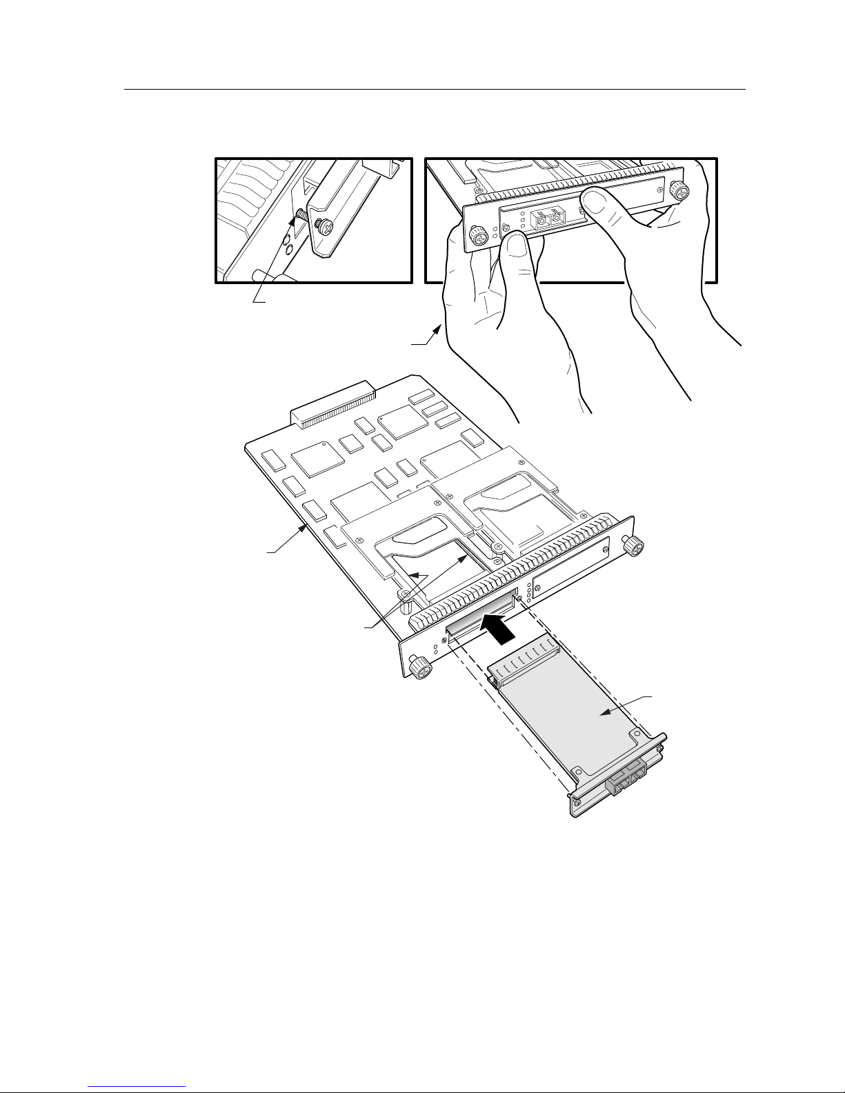
Seat screws into
mounting holes,
then press PHY card
to fully engage connector
Chapter 2: Hardware Installation
ATM Board
Guide Rails
Phy Card
Figure 38. Installing an ATM PHY card
SSR 8000/8600 Getting Started Guide 69
Page 84
Chapter 2: Hardware Installation
To install a PHY card into an ATM line card:
1. Use a Phillips-head screwdriver to loosen the two captive screws that hold the option
slot cover in place.
2. Save the option slot cover.
3. Hold the PHY card by the edges and position it so that it is parallel with the slot
opening.
4. Insert the PHY card through the opening in the system unit by aligning the sides of
the PHY card with the card guide.
5. Push the PHY card into the slot until the 96-pin connector is firmly seated on the
motherboard.
6. Fasten the PHY card to the system unit with the two captive screws. Torque to 5 in-lb
(0.56 N-m).
Attaching the Console Management Cables
The Control Module has two ports for attaching management consoles to the SSR.
• A male DB-9 DCE port for direct serial connection from a terminal. You use this port to
perform basic setup, including setting up the SSR for management through the
network using CoreWatch or SNMP.
• An RJ-45 10/100Base-T DTE port for Telnet connection from a host on the network. The
port is configured for Media Data Interface (MDI). You use this port to manage the SSR
using CoreWatch or SNMP.
Connecting to the Serial Port
To attach the supplied console cable to the Control Module DB-9 port:
1. Locate the console cable included with the SSR chassis. The console cable is a femaleto-female DB-9 crossover cable. Thus, pin 2 (TXD or “transmit data”) emerges on the
management console’s end of the connection as RXD (“receive data”), and so on.
The following table lists the pin assignments for the male DB-9 connector on the
Control Module and for the male DB-9 connector on the management console.
Control Module DB-9
Connector (DCE)
Pin Number Management Console DB-9
Connector (DTE)
Unused 1 Unused
TXD (transmit data) 2 RXD (receive data)
RXD (receive data) 3 TXD (transmit data)
70 SSR 8000/8600 Getting Started Guide
Page 85
Chapter 2: Hardware Installation
Control Module DB-9
Connector (DCE)
Unused 4 Unused
GND (ground) 5 GND (ground)
DTR (data terminal ready) 6 DSR (data set ready)
CTS (clear to send) 7 RTS (request to send)
RTS (request to send) 8 CTS (clear to send)
Unused 9 Unused
2. Plug one end of the console cable into the Control Module’s DCE DB-9 port.
3. Plug the other end of the console cable into the management console’s DTE port.
4. When you are ready to begin configuring the SSR, use procedures in Chapter 3 to
power on the switch and boot the software. You will perform initial setup by entering
CLI commands on the management console.
Connecting to the 10/100Base-TX Port
Pin Number Management Console DB-9
Connector (DTE)
Use the RJ-45 10/100Base-TX DTE port for Telnet connection from a host on the network.
The port is configured for Media Data Interface (MDI).
To attach a cable to the 10/100Base-TX port:
1. Obtain a cable with an RJ-45 connector. Pin 1 (TXD or “transmit data”) must emerge
on the management console’s end of the connection as RXD (“receive data”) and so
on.
The following table lists the pin assignments for the RJ-45 connector on the Control
Module and for the RJ-45 connector on the management console.
Control Module RJ-45
Connector
Pin Number Management Console RJ-45
Connector
TXD (transmit data) 1 RXD (receive data)
TXD (transmit data) 2 RXD (receive data)
RXD (receive data) 3 TXD (transmit data)
Unused 4 Unused
Unused 5 Unused
SSR 8000/8600 Getting Started Guide 71
Page 86
Chapter 2: Hardware Installation
Control Module RJ-45
Connector
RXD (receive data) 6 TXD (transmit data)
Unused 7 Unused
Unused 8 Unused
2. After ensuring that the pin assignments on both ends of the connection are correct,
plug the appropriate end of the connection into the Control Module’s RJ-45
10/100Base-TX port.
3. Plug the other end of the connection into the management console’s port.
4. When you are ready to configure the SSR using CoreWatch or SNMP, use procedures
in Chapter 4 to start an SNMP or CoreWatch management session.
Attaching the Segment Cables
The following sections describe how to connect the SSR line cards to your network.
10/100Base-TX Line Card
Pin Number Management Console RJ-45
Connector
To attach the segment cables to your 10/100Base-TX line cards:
1. For all the 10/100-Mbps ports, obtain copper cables that have the following pin
assignments. The RJ-45 connectors on the 10/100Base-TX line cards are configured as
Media Data Interface Crossed (MDIX). You can use Category 3 (“Cat-3”) or higher
wire for 10-Mbps segments. For 100-Mbps segments, use Cat-5 or higher wire. The
ports automatically sense which type of segment they are connected to and configure
themselves to transmit and receive at the appropriate bandwidth.
The following table lists the pin assignments for the RJ-45 connector on the
10/100Base-TX and for the RJ-45 connector on the switch, router, or host on the other
end of the segment cable.
Line Card RJ-45 Connector Pin Number RJ-45 Connector at Other
End of Segment
RXD (receive data) 1 TXD (transmit data)
RXD (receive data) 2 TXD (transmit data)
TXD (transmit data) 3 RXD (receive data)
Unused 4 Unused
Unused 5 Unused
72 SSR 8000/8600 Getting Started Guide
Page 87
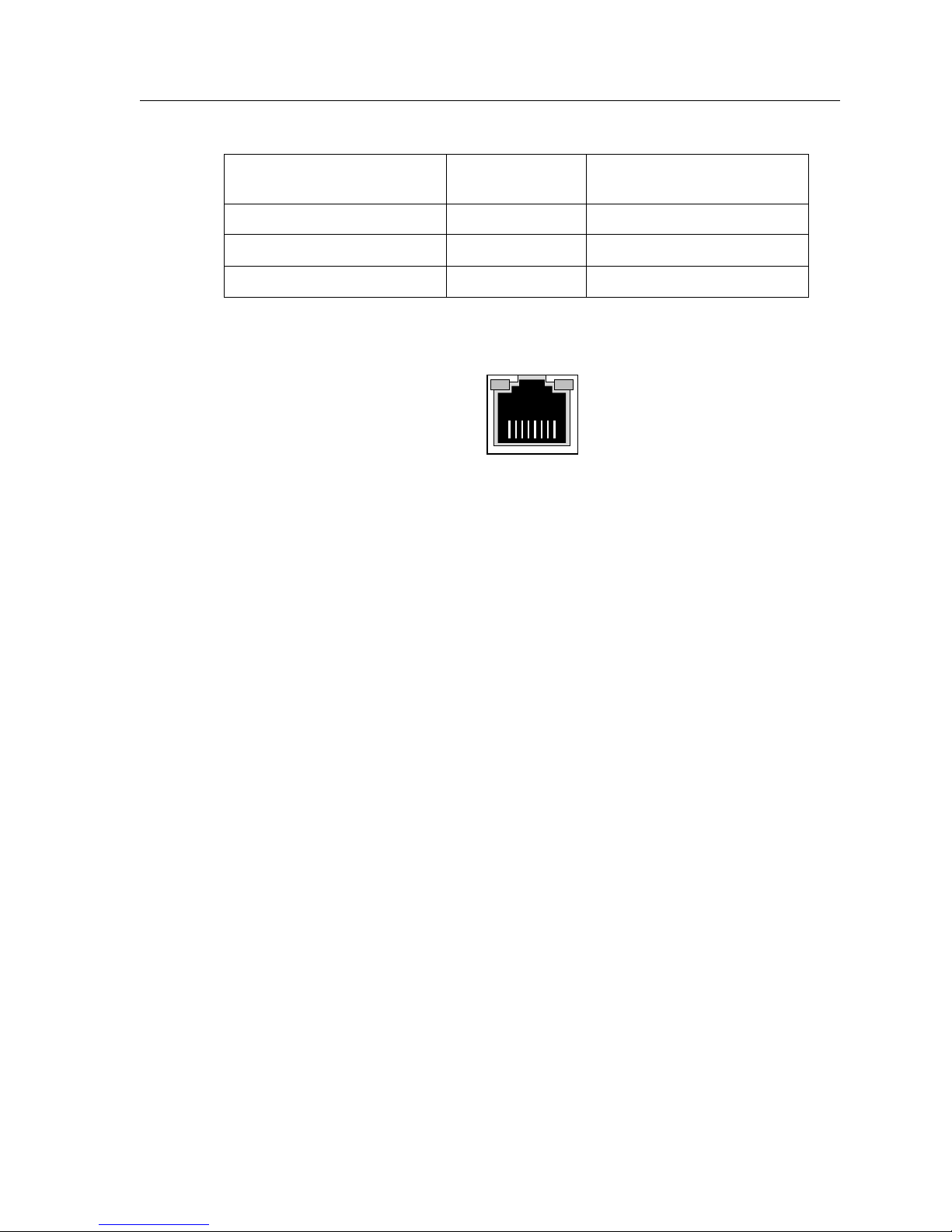
Chapter 2: Hardware Installation
Line Card RJ-45 Connector Pin Number RJ-45 Connector at Other
End of Segment
TXD (transmit data) 6 RXD (receive data)
Unused 7 Unused
Unused 8 Unused
Figure 39 shows the pin positions in the 10/100Base-TX connectors.
87654321
Figure 39. 10/100Base-TX RJ-45 connector
2. Plug one end of the cable into the line card and the other end into the hardware at the
other end of the connection.
1000Base-T Line Card
To attach the segment cables to your 1000Base-T line cards:
1. For all the 1000-Mbps ports, obtain copper cables that have the following pin
assignments. The RJ-45 connectors on the 1000Base-T line cards are configured as
Media Data Interface Crossed (MDIX). Use Cat-5 or higher wire.
2. Plug one end of the cable into the line card and the other end into the hardware at the
other end of the connection.
Note: You may use either crossover or straight cables. The ports uses internal logic to
accommodate either crossover wire or straight wire.
Note: The 1000Base-T line card does not support 10/100 Mbps traffic.
SSR 8000/8600 Getting Started Guide 73
Page 88
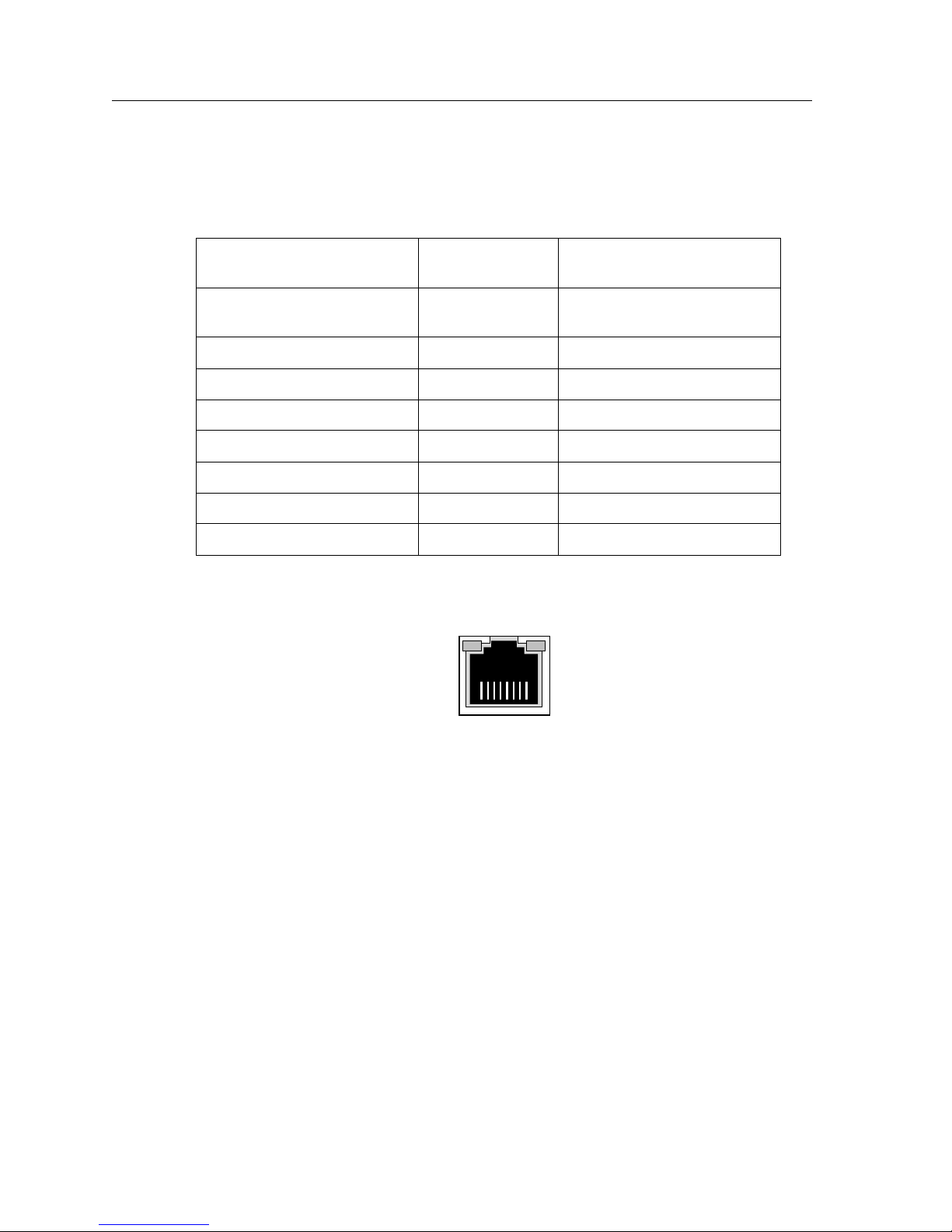
Chapter 2: Hardware Installation
The following table lists the pin assignments for the RJ-45 connector on the 1000Base-T
and for the RJ-45 connector on the switch, router, or host on the other end of the segment
cable.
Line Card RJ-45 Connector Pin Number RJ-45 Connector at Other
End of Segment
TXD and RXD (transmit and
1 TXD and RXD
receive data)
TXD and RXD 2 TXD and RXD
TXD and RXD 3 TXD and RXD
TXD and RXD 4 TXD and RXD
TXD and RXD 5 TXD and RXD
TXD and RXD 6 TXD and RXD
TXD and RXD 7 TXD and RXD
TXD and RXD 8 TXD and RXD
Figure 40 shows the pin positions in the 1000Base-T connectors.
87654321
Figure 40. 1000Base-T RJ-45 connector
1000Base-SX Line Card and 100Base-FX Line Card
The 1000Base-SX line card and the 100Base-FX line cards use SC-style Media Interface
Connectors (MICs) to attach to multimode fiber (MMF) cables.
To attach the segment cables to your 1000Base-SX line card or 100Base-FX line cards,
obtain an MMF cable with an SC MIC and plug the MIC into the port connector. When
you plug the other end of the cable into another device, ensure that the cable connected to
the transmit port on the SSR is connected to the receive port on the other device. The
receive port on the SSR should be connected to the transmit port on the other device.
74 SSR 8000/8600 Getting Started Guide
Page 89

1000Base-LX Line Card
The 1000Base-LX line card supports single-mode fiber (SMF) or multimode fiber (MMF).
The installation instructions for the 1000Base-LX line card are the same as the instructions
for the 1000Base-SX line card.
Chapter 2: Hardware Installation
SSR 8000/8600 Getting Started Guide 75
Page 90

Chapter 2: Hardware Installation
ATM PHY Card
The following are instructions on how to attach cables to the various PHY interface cards
for the ATM line card.
APHY-67 and APHY-77
To attach the segment cables to your APHY-67 and APHY-77 card:
1. Align the transmit cable connector with the transmit port and the receive cable
connector with the receive port.
2. Push one connector into the PHY port and rotate clockwise 1/4 turn to lock it in place.
3. Repeat step 2 for the second cable.
APHY-82 and APHY-92
To attach the segment cables to your APHY-82 and APHY-92 card:
1. Align the key of the modular jack (MJ) plug with the locking key of the MJ receptacle.
2. Push the MJ plug into the receptacle until the plug mates fully with the locking key.
You will hear a snapping sound when the locking key engages.
APHY-21 and APHY-29IR
To attach the segment cables to your APHY-21 and APHY-29IR card:
1. Remove the dust caps from the PHY port and cable.
2. Line up the transmit cable connector with the transmit port and the receive cable
connector with the receive port. Insert the connectors, ensuring that the key is
correctly positioned
APHY-22
To attach the segment cables to your APHY-22 card:
1. Align the key of the modular jack (MJ) plug with the locking key of the MJ receptacle.
2. Push the MJ plug into the receptacle until the plug mates fully with the locking key.
You will hear a snapping sound when the locking key engages.
76 SSR 8000/8600 Getting Started Guide
Page 91
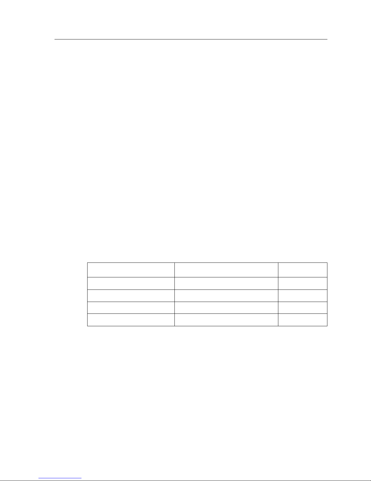
POS OC-3c Line Card
The POS OC-12c line card use MT-RJ connectors to attach to multimode fiber (MMF) and
singlemode MT-RJ cables.
To attach the segment cables to your POS OC-12c line card, obtain a MT-RJ cable and plug
the connector on one end into the port connector. Plug the other end into the port of the
other device. Since MT-RJ cables consist of only one line, there are no concerns about
matching the receive port with the transmit port.
POS OC-12c Line Card
The POS OC-12c line card use SC-style Media Interface Connectors (MICs) to attach to
multimode fiber (MMF) and singlemode (SMF) cables. The installation instructions for the
POS line card are the same as the instructions for the 1000Base-SX line card.
Quad Serial – C and Quad Serial – CE Line Cards
The Quad Serial – C/CE line cards each use the same 60-pin LFH-60 high density
connector to link to their respective Channel Service Units/Data Service Units
(CSU/DSUs).
Chapter 2: Hardware Installation
Cabletron offers the following four cables, used to connect the Quad Serial – C/CE line
cards to standard CSU/DSU modules:
Cabletron Part Number CSU/DSU Connector Type Standard
SSR-V35DTE-02 Two (2) V.35 34-pin connectors
a
V. 3 5
SSR-530DTE-02 Two (2) DB-25 25-pin connectors EIA-530
SSR-449DTE-02 Two (2) DB-37 37-pin connectors RS-449
SSR-X21DTE-02 Two (2) DB-15 15-pin connectors X.21
a. The two remote ends of each type of connector cable are labeled “Port A” and “Port B”. “Port A”
corresponds to Port 1 or 3 on a Quad Serial – C/CE WAN card, depending upon which line card port
you are using. Similarly, “Port B” corresponds to Port 2 or 4 on a Quad Serial – C/CE line card.
Note: Because the LFH-60 high density connectors on Quad Serial – C/CE line cards
contain two serial WAN ports per interface, all four cable types defined above
feed two CSU/DSU ports.
SSR 8000/8600 Getting Started Guide 77
Page 92
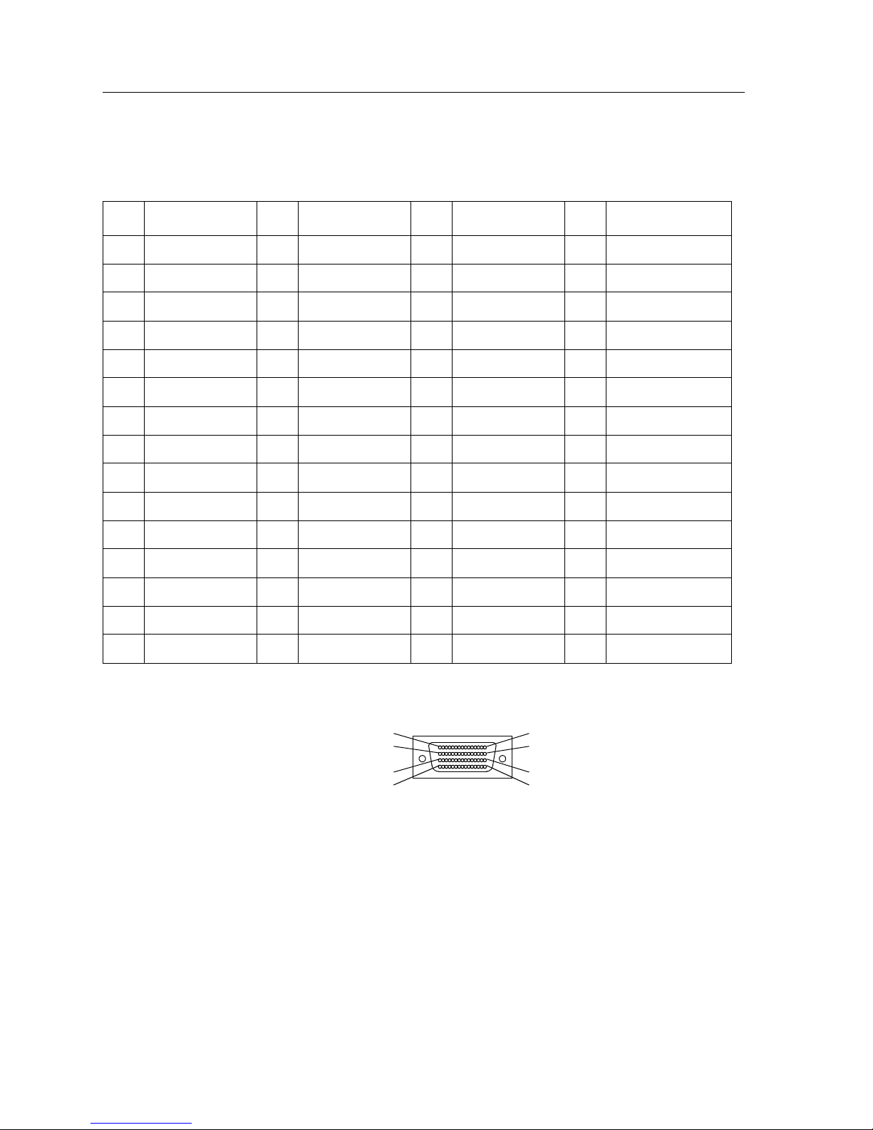
Chapter 2: Hardware Installation
The following table maps the pin assignments for Cabletron’s LFH-60 high density
connectors for the Quad Serial – C/CE line cards.
Pin Signal Pin Signal Pin Signal Pin Signal
1 P1_GND 16 P2_TXC_A 31 P1_GND 46 P2_TXD_A
2 P1_MODE[2] 17 P2_TXC_B 32 P1_MODE[0] 47 P2_TXD_B
3 P1_CTS_B 18 P2_DCD_A 33 P1_DCD_B 48 P2_RTS_A
4 P1_CTS_A 19 P2_DCD_B 34 P1_DCD_A 49 P2_RTS_B
5 P1_RTS_B 20P2_MODE[1] 35P0_RXD_B 50P2_DSR_A
6 P1_RTS_A 21 P2_GND 36 P0_RXD_A 51 P2_DSR_B
7 P1_SCTE_B 22 P2_GND 37 Reserved 52 P2_LL_A
8 P1_SCTE_A 23 P1_TXD_A 38 P2_GND 53 P2_SHIELD
9 P1_GND 24 P1_TXD_B 39 P2_MODE[0] 54 Reserved
10 P2_GND 25 P1_TXC_A 40 P2_CTS_B 55 P1_RXC_A
11P2_MODE[2] 26P1_TXC_B 41P2_CTS_A 56P1_RXC_B
12 P2_RXD_B 27 P1_DSR_A 42 P2_DTR_B 57 P1_DTR_A
13 P2_RXD_A 28 P1_DSR_B 43 P2_DTR_A 58 P1_DTR_B
14 P2_RXC_B 29 P1_MODE[1] 44 P2_SCTE_B 59 P1_LL_A
15 P2_RXC_A 30 P1_GND 45 P2_SCTE_A 60 P1_SHIELD
Figure 41 shows the pin positions in the LFH-60 high density connector.
1
30
31
60
15
16
45
46
Figure 41. LFH-60 high density connector
Cabletron Quad Serial – C/CE line cards use standard copper twisted-pair cable with one
of four custom remote-end connectors to attach to their respective CSU/DSU modules.
78 SSR 8000/8600 Getting Started Guide
Page 93

Chapter 2: Hardware Installation
To attach the segment cables to your Quad Serial – C/CE line card:
1. Obtain one of the Cabletron connector cables described on page 77 and connect the
single LFH-60 high density connector to the SSR WAN interface you wish to use.
2. Plug the remote end of the connector for each port you wish to use into its respective
CSU/DSU data port.
Dual HSSI Line Card
The Dual HSSI line card uses a 50-pin High Speed Serial Interface (HSSI) connector to link
to a Channel Service Unit/Data Service Unit (CSU/DSU). Cabletron offers a 3 meter (10
foot) 50-pin HSSI connector cable (part number SSR-HSSI-CAB) to connect Dual HSSI
line cards to remote CSU/DSU modules.
The following table maps the pin assignments for Cabletron’s 50-pin HSSI connector for
the Dual HSSI line card.
Pin Signal Pin Signal Pin Signal Pin Signal
1 GND 14 (reserved) 26 GND 39 (reserved)
2 RT+ 15 (reserved) 27 RT- 40 (reserved)
3 CA+ 16 (reserved) 28 CA- 41 (reserved)
4 RD+ 17 (reserved) 29 RD- 42 (reserved)
5 LC+ 18 (reserved) 30 LC- 43 (reserved)
6 ST+ 19 GND 31 ST- 44 GND
7 GND 20 (reserved) 32 GND 45 (reserved)
8 TA+ 24 (reserved) 33 TA- 46 (reserved)
9 TT+ 22 (reserved) 34 TT- 47 (reserved)
10 LA+ 23 (reserved) 35 LA- 48 (reserved)
11 SD+ 24 (reserved) 36 SD- 49 (reserved)
12 LB+ 25 GND 37 LB- 50 GND
13 GND 38 GND
Note: Because neither connector at the ends of the SSR-HSSI-CAB cable is keyed, you
can simply plug either end of the cable into either your Dual HSSI line card or the
remote HSSI CSU/DSU data port.
SSR 8000/8600 Getting Started Guide 79
Page 94
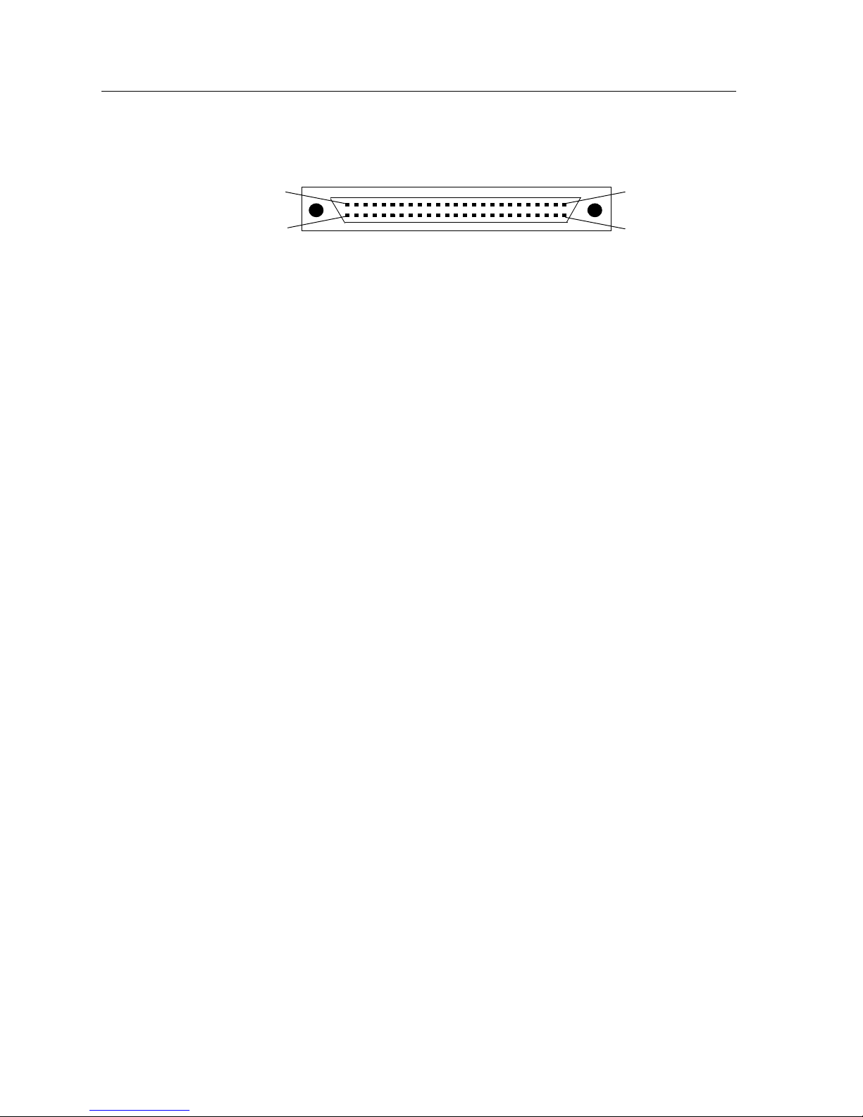
Chapter 2: Hardware Installation
Figure 42 shows the pin positions in the 50-pin HSSI connector.
25
1
2650
Figure 42. 50-pin HSSI connector
The Cabletron Dual HSSI line card uses standard copper twisted-pair cable with identical
50-pin HSSI connectors at each end to attach to a CSU/DSU module.
To attach the segment cables to your Dual HSSI line card:
1. Obtain a Cabletron 50-pin HSSI connector cable (part number SSR-HSSI-CAB) and
connect either end of the HSSI connector cable to the SSR WAN interface you wish to
use.
2. Plug the remote end of the connector cable into the HSSI CSU/DSU data port you
wish to use.
80 SSR 8000/8600 Getting Started Guide
Page 95

Chapter 3
Software Installation
and Setup
This chapter provides the following SmartSwitch Router (SSR) software installation and
basic setup procedures:
• Installing the PCMCIA flash card (if you are upgrading from the software version on
the SSR’s boot flash)
• Powering on the SSR and booting the software
• Starting the Command Line Interface (CLI)
• Using the CLI to add an IP interface, subnet mask, and default gateway for CoreWatch
access
• Setting up passwords
• Setting up an SNMP community string and trap target
• Setting the DNS server’s IP address(es) and domain name
• Setting the SYSLOG server and message level
• Upgrading system image software
• Upgrading the boot PROM software
• Activating and saving configuration changes
SSR 8000/8600 Getting Started Guide 81
Page 96

Chapter 3: Software Installation and Setup
Installing a PCMCIA Flash Card
The Control Module PCMCIA flash card contains a version of the system image software
that is installed at the factory. If you have a more recent system image and want to boot
the SSR using the newer software, you must boot either from a PCMCIA card or from a
TFTP server.
To install a PCMCIA card:
1. Power off the SSR. You cannot install or remove a PCMCIA card while the SSR is
running.
2. Insert the PCMCIA card into either of the slots on the Control Module. You can choose
either slot.
Note:
Even though there are two slots on the Control Module, you cannot use two
PCMCIA flash cards at the same time.
3. Lock the PCMCIA card into the slot by pushing the PCMCIA card all the way into the
slot.
4. Power on the SSR. (See “Powering On and Booting the Software” on page 83.)
5. To verify proper installation of the PCMCIA card, do one of the following:
– Reboot the system and watch the boot messages for the messages shown in bold
type in the following example:
%SYS-I-FLASHCRD, Mounting 8MB Flash card
%SYS-I-FLASHMNTD, 8MB Flash card mounted
%SYS-I-INITSYS, initializing system (unknown)
%SYS-I-DSCVMOD, discovered 'Control Module' module in slot CM
%SYS-I-DSCVMOD, discovered '10/100-TX' module in slot CM/1
%SYS-I-DSCVMOD, discovered '10/100-TX' module in slot 3
%SYS-I-DSCVMOD, discovered '10/100-TX' module in slot 4
%SYS-I-DSCVMOD, discovered '10/100-TX' module in slot 7
%SYS-I-INITPORT, initialized slot CM/1, port 1
%SYS-I-INITPORT, initialized slot CM/1, port 2
%SYS-I-INITPORT, initialized slot CM/1, port 3
%SYS-I-INITPORT, initialized slot CM/1, port 4
%SYS-I-INITPORT, initialized slot CM/1, port 5
%SYS-I-INITPORT, initialized slot CM/1, port 6
%SYS-I-INITPORT, initialized slot CM/1, port 7
%SYS-I-INITPORT, initialized slot CM/1, port 8
%SYS-I-INITPORT, initialized slot 3, port 1
%SYS-I-INITPORT, initialized slot 3, port 2
%SYS-I-INITPORT, initialized slot 3, port 3
%SYS-I-INITPORT, initialized slot 3, port 4
%SYS-I-INITPORT, initialized slot 3, port 5
%SYS-I-INITPORT, initialized slot 3, port 6
%SYS-I-INITPORT, initialized slot 3, port 7
%SYS-I-INITPORT, initialized slot 3, port 8
82 SSR 8000/8600 Getting Started Guide
Page 97

Chapter 3: Software Installation and Setup
– Run the following command to display the boot log and look for the messages
shown in the example above:
system show bootlog
Note: If the message “SYS-E-NOFLASHCARD” appears, the system has not detected a
PCMCIA card. Check to ensure that the card is properly inserted, then reboot. If
the system still does not recognize the card, contact Cabletron Systems. (See
“Technical Support” on page 111.)
Powering On and Booting the Software
To power on the SSR and boot the software:
1. Make sure all exposed line card slots and power supply bays are free of foreign
objects, such as tools, and are covered with coverplates.
2. Check the power supplies to make sure they are attached to your power source.
3. Turn the switch on each power supply to the ON position.
4. If this is the first time you have powered on the SSR, it will automatically try to boot
using the software image in the Control Module’s boot flash.
While the software is booting, the amber Offline LED on the Control Module is lit.
When the software finishes booting, the Offline LED goes dark and the green Online
LED lights up, indicating that the SSR software is online. As the software boots, the
management console attached to the Control Module’s DB-9 DCE port displays
messages related to the phases of the boot sequence. When the software is fully booted,
the following message appears on the management console:
Press RETURN to activate console...
5. As prompted, press Return (or Enter) to activate the CLI on the console.
Starting the Command Line Interface
To start the Command Line Interface (CLI), power on the system. Startup messages
appear on the console (the terminal attached to one of the Control Module’s ports).
After the software is fully booted and you press Return (or Enter) to activate the CLI, the
CLI prompts you for a password. You can define separate passwords for login access,
Enable mode, and Configure mode (defined below). The factory default password for all
three is set to blank. (Simply press Return.)
SSR 8000/8600 Getting Started Guide 83
Page 98

Chapter 3: Software Installation and Setup
Access Modes
The SSR CLI has four access modes.
• User – Allows you to display basic information and use basic utilities such as ping but
does not allow you to display SNMP, filter, and access control list information or make
other configuration changes. You are in User mode when the command prompt ends
with the “
• Enable – Allows you to display SNMP, filter, and access control information as well as
all the information you can display in User mode. To enter Enable mode, enter the
enable command, then supply the password when prompted. When you are in Enable
mode, the command prompt ends with the “
• Configure – Allows you to make configuration changes. To enter Configure mode, first
enter Enable mode (enable command), then enter the configure command from the
Enable command prompt. When you are in Configure mode, the command prompt
ends with “
• Boot – This mode appears when the SSR, external flash card, or the system image is not
found during bootup. You should enter the reboot command to reset the SSR. If the
SSR still fails to boot, contact Cabletron Systems. (See “Technical Support” on page
111.)
>”character.
(config).”
#” character.
Note:
The command prompt will show the name of the SSR in front of the mode
character(s). The default name is “ssr”. The procedure in “Setting the Basic
System Information” on page 86 describes how to change the system name.
When you are in Configure or Enable mode, use the exit command or press Ctrl+Z to exit
to the previous access mode.
Note:
When you exit Configure mode, the CLI will ask you whether you want to
activate the configuration commands you have issued. If you type Y (Yes), the
configuration commands you issued are placed into effect and the SSR’s
configuration is changed accordingly. However, the changes are not written to the
Startup configuration file in the Control Module’s boot flash and therefore are not
reinstated after a reboot. See “Activating the Configuration Changes and Saving
the Configuration File” on page 98 for information about saving configuration
changes.
84 SSR 8000/8600 Getting Started Guide
Page 99

Basic Line Editing Commands
The CLI supports Emacs-like line editing commands. The following table lists some
commonly used commands. For a complete set of commands, see the SmartSwitch Router
User Reference Manual.
Key sequence Command
Ctrl+A Move cursor to beginning of line
Ctrl+B Move cursor back one character
Ctrl+D Delete character
Ctrl+E Move cursor to end of line
Ctrl+F Move cursor forward one
character
Ctrl+N Scroll to next command in
command history (use the cli
show history command to
display the history)
Chapter 3: Software Installation and Setup
Ctrl+P Scroll to previous command in
command history
Ctrl+U Erase entire line
Ctrl+X Erase from cursor to end of line
Ctrl+Z Exit current access mode to
previous access mode
SSR 8000/8600 Getting Started Guide 85
Page 100
Chapter 3: Software Installation and Setup
Setting the Basic System Information
Use the procedure in this section to set the following system information:
• System time and date
• System name
• System location
• Contact name (the person to contact regarding this SSR)
• IP address for the management port on the Control Module
Note:
Some of the commands in this procedure accept a string value. String values can
be up to a maximum of 255 characters in length including blank spaces. Surround
strings that contain blanks with quotation marks (for example: “string with
internal blanks”).
1. Enter the enable command to get to Enable mode in the CLI.
2. Enter the following commands to set the system time and date and then verify the
setting:
system set date year <number> month <month-name> day <day>
hour <hour> minute <minute> second <second>
system show date
Here is an example:
ssr# system set date year 1999 month june day 14 hour 11 minute 54
second 0
Time changed to: Mon Jun 14 11:54:00 1999
ssr# system show date
Current time: Mon Jun 14 11:54:04 1999
3. Enter the configure command to get to Configure mode in the CLI. The following
commands can be entered only from Configure mode.
4. Enter the following commands to set the system name, location, and contact
information:
system set name “<string>”
system set location “<string>”
system set contact “<string>”
86 SSR 8000/8600 Getting Started Guide
 Loading...