

Page 1

6C110 POWER BRIDGE ADAPTER
INSTALLATION INSTRUCTIONS
This upgrade kit contains the power bridge adapter that, when properly installed, allows the 6C110 chassis to
support the 6C210-1 and 6C210-2 power supplies.
Only qualified personnel should perform the following installation procedures.
Required T ools
The following tools are required to install the 6C110 power bridge adapter:
• ESD wrist strap
• Phillips head screwdriver
• Flat head screwdriver
• Hex nut driver (.25-inch)
Equipment Checklist
Ensure the upgrade kit contains the following items before proceeding with the installation. If any components are
missing, contact Cabletron Systems. Information on contacting Cabletron Systems is available at the end of this
document.
• Power Bridge Adapter (1)
• Standoffs (3)
• Support Clip (1)
• Blank Faceplate (1)
Related Manuals
Use the 6C110 Overview and Setup Guide to supplement the procedures and other technical data provided in this
manual:
This manual can be obtained on the World Wide Web in Adobe Acrobat Portable Document Format (PDF) at the
following site:
http://www.cabletron.com/
9033011 Page 1 of 7
Page 2
6C110 Power Bridge Adapter Installation Instructions
Installing the Power Bridge Adapter
These instructions apply to users that will equip the 6C110 chassis with 6C210-1 or
!
CAUTION
This section provides instructions on installing the power bridge adapter to allow the 6C110 chassis to support the
6C210-1 or 6C210-2 power supplies. If the legacy 6C205-2 or 6C205-3 power supplies will be used, DO NOT
install the power bridge adapter.
To install the power bridge adapter, perform the following steps:
1. Attach the ESD wrist strap.
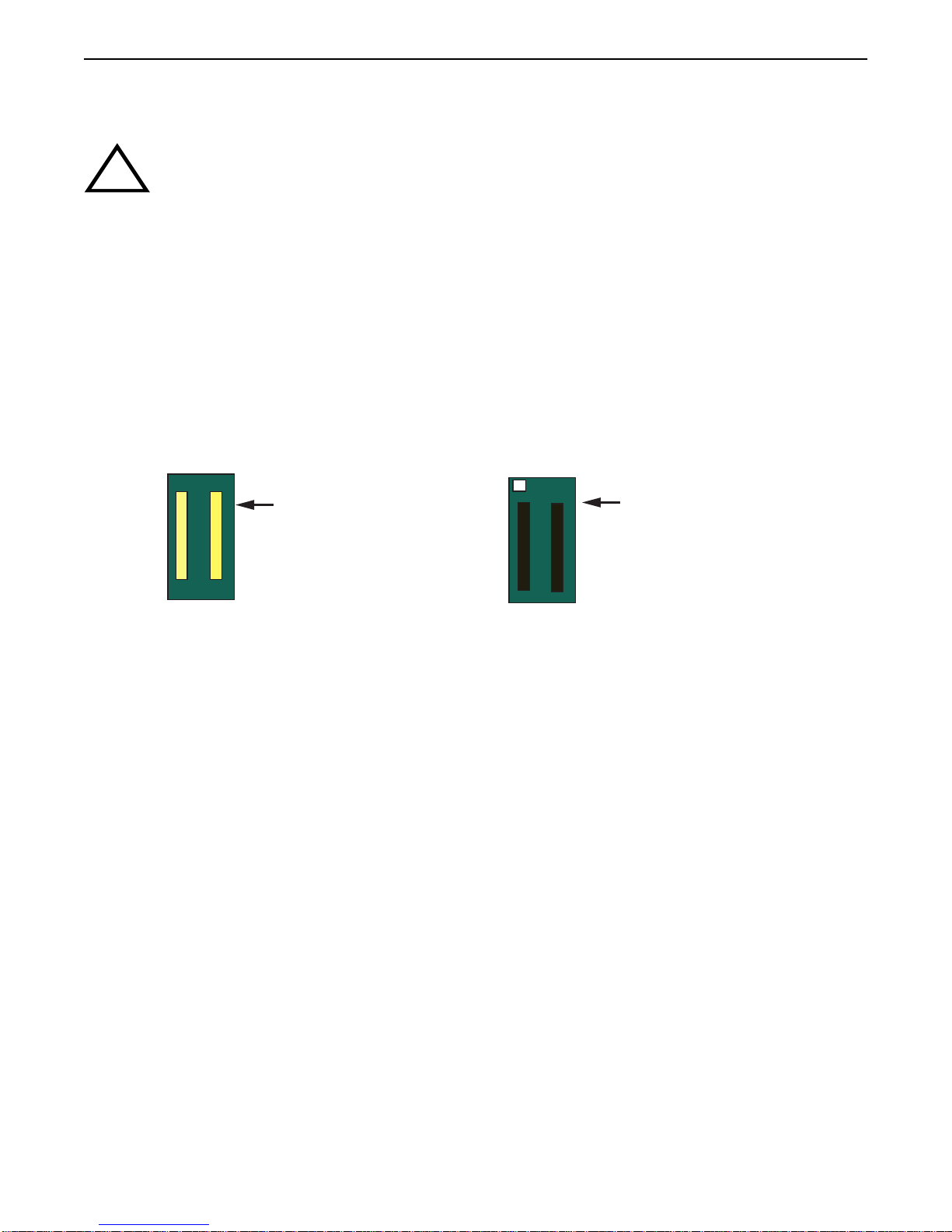
2. Refer to Figure 1 to identify the front and rear sides of the power bridge adapter.
6C210-2 power supplies. If legacy 6C205-2 or 6C205-3 power supplies will be used, DO
NOT install the power bridge adapter.
All Cabletron Systems interface modules are sensitive to static discharges. Use an ESD
wrist strap and observe all static precautions during this procedure. Failure to do so could
damage the backplane of the 6C110.
Power Bridge Adapter
(Front, White Connectors)
Figure 1 Power Bridge Adapter (Front and Back)
Power Bridge Adapter
(Rear, Black Connectors)
9033011 Page 2 of 7
Page 3
6C110 Power Bridge Adapter Installation Instructions
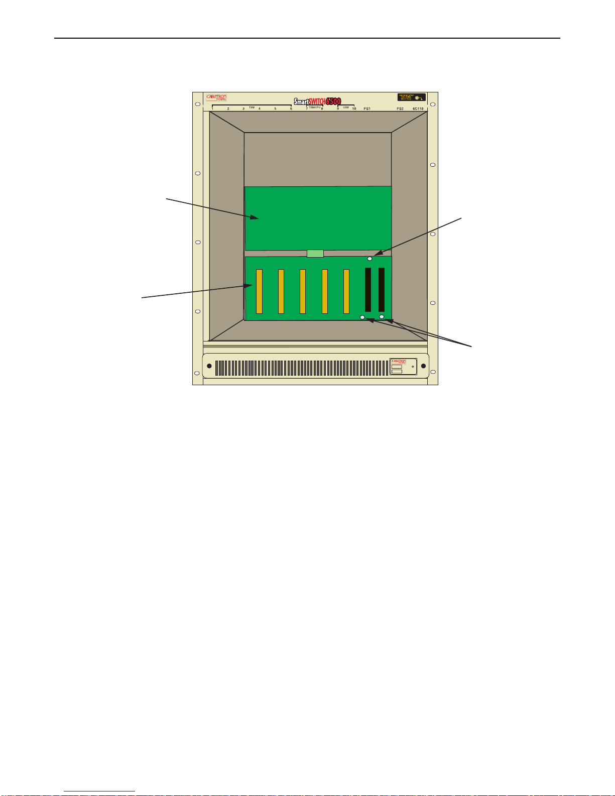
3. Remove the three screws from the lower backplane, as shown in Figure 2.
Upper Backplane
Screw
Lower Backplane
Screws(2)
6C405
Figure 2 Removing the Screws
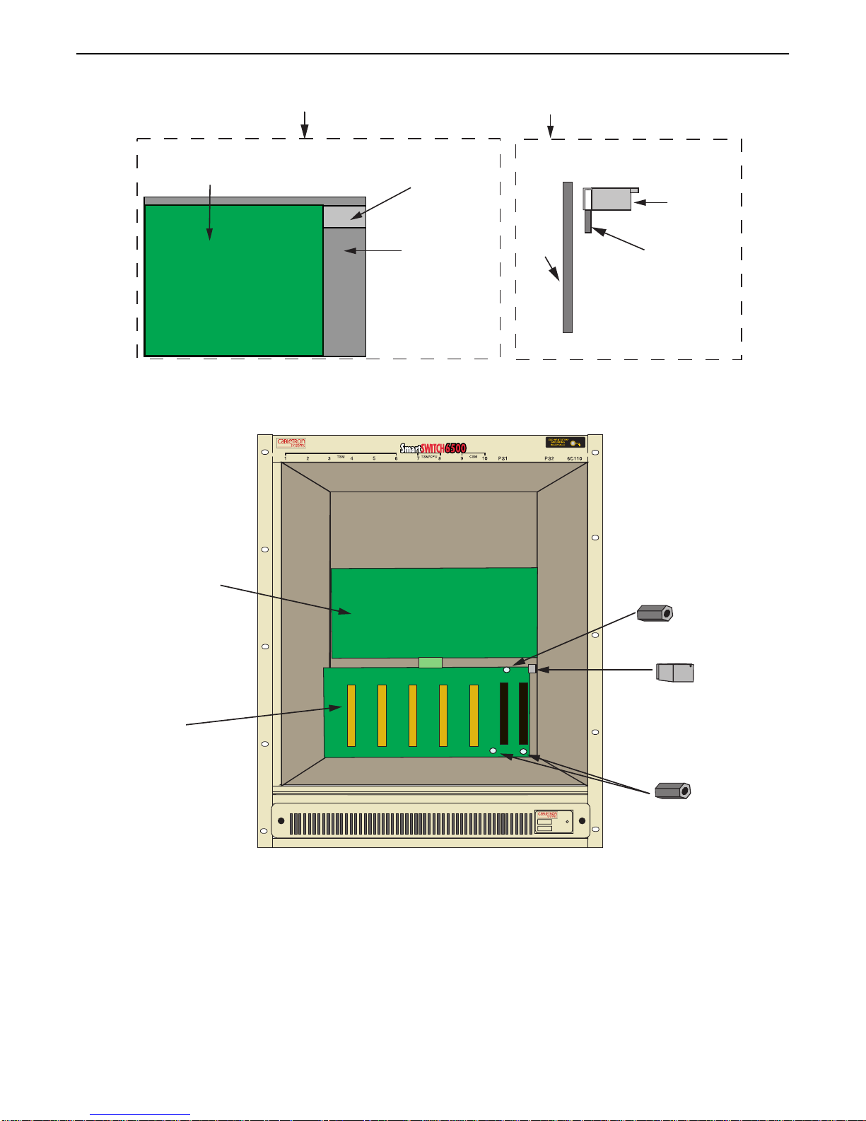
4. Using a .25-inch hex nut driver, install the three standoffs into the holes that held the screws removed in step 3.
See Figure 4.
5. Install the support clip by sliding the notched end over the rear chassis card cage, in the space provided next to
the upper right hand corner of the lower backplane. Refer to Figure 3 and Figure 4.
9033011 Page 3 of 7
Page 4
6C110 Power Bridge Adapter Installation Instructions
Front View of Support Clip Installation Location
Upper Right Hand Corner
of Lower Backplane
Side View of Installation
Chassis Card Cage
Back
Panel
of
Back Panel
of Chassis
Chassis
Figure 3 Installing the Support Clip
Support Clip
Chassis Card Cage
Upper Backplane
Lower Backplane
Figure 4 Installing the Standoffs
Standoff
Support Clip
6C405
Standoffs (2)
9033011 Page 4 of 7
Page 5
6C110 Power Bridge Adapter Installation Instructions
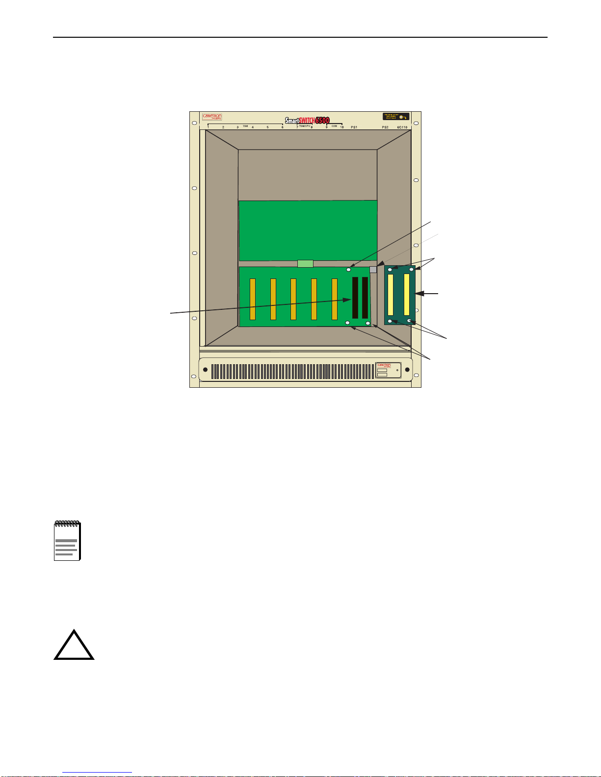
6. Connect the rear (black) power bridge adapter connectors to the lower backplane connectors of the chassis.
Ensure that the connectors are firmly seated together, and the screw holes of the power bridge adapter align with
the standoffs installed in step 4 and the support clip installed in step 5. See Figure 5.
Standoff
Support Clip
Screw Holes (2)
Power Bridge
Adapter
Lower Backplane
Connectors (2)
Screw Holes (2)
6C405
Figure 5 Installing the Power Bridge Adapter
Standoffs (2)
7. Attach the power bridge adapter to the lower backplane by fastening the three screws to the standoffs installed
in step 4 and one screw to the support lip installed in step 5. See Figure 5.
Installation is complete.
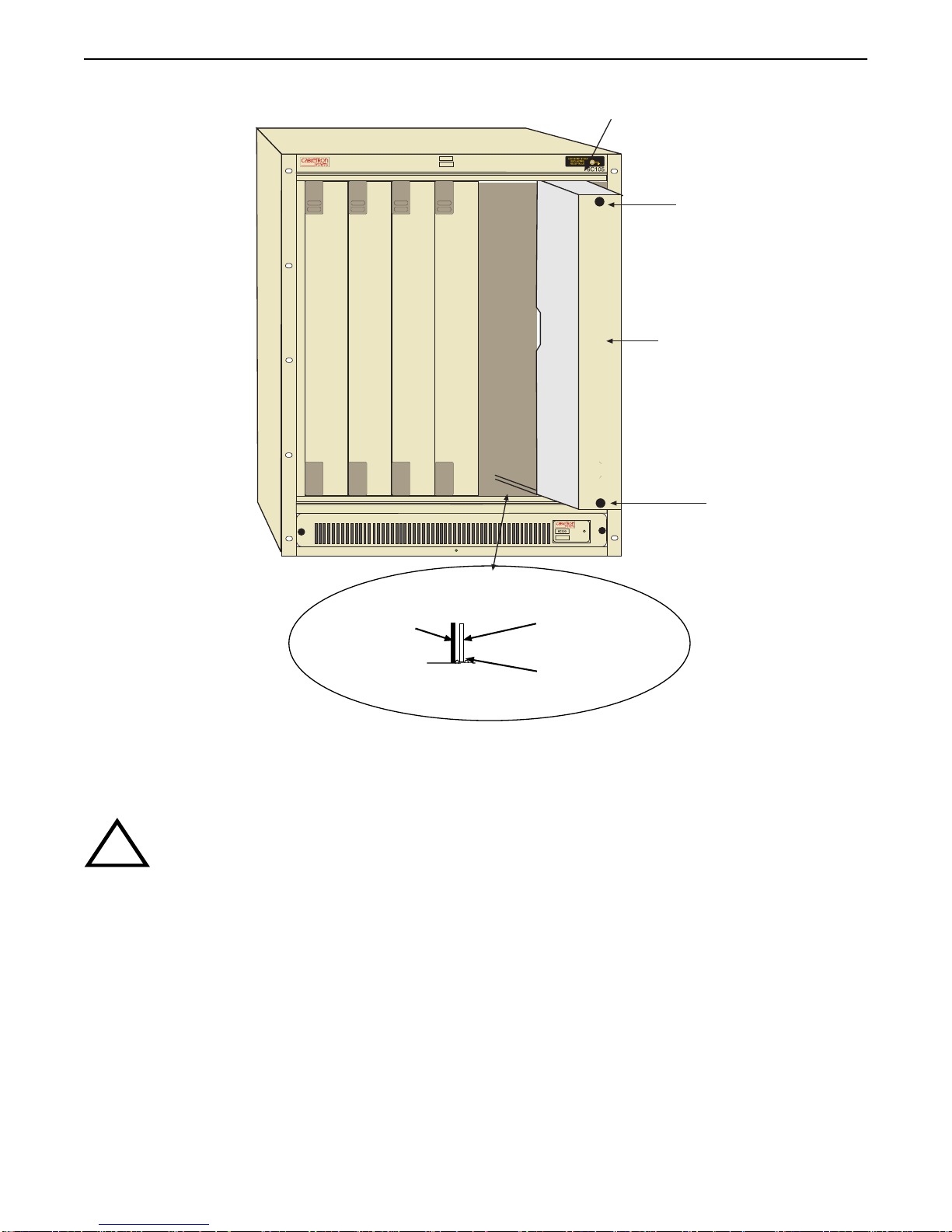
Installing the Blank Faceplate
NOTE
If the 6C110 chassis will be equipped with a single power supply only, the blank faceplate included with the
upgrade kit must be installed in the slot labeled “PS2”.
To install the blank faceplate, refer to Figure 6 and proceed as follows:
The following instructions should be performed only when a single power supply is
installed in the 6C110 chassis.
If the 6C110 is configured with a single power supply module, it must be located in slot PS1.
!
CAUTION
9033011 Page 5 of 7
Page 6
6C110 Power Bridge Adapter Installation Instructions
Slot PS2
PS1
1
2345
PS2
Slotted Screw
Blank Faceplate
Slotted Screw
Metal Back-Panel
Plastic Guide Runner
Card Guide
Figure 6 Installing the Blank Faceplate
1. Align the plastic guide runner of the blank faceplate with the slotted paths on the top and bottom of the opening.
Forcing a misaligned blank faceplate into place can damage the chassis backplane.
!
CAUTION
2. With the blank faceplate inserted into the slotted paths, carefully slide the module forward until the front panel
of the blank faceplate is flush with the face of the 6C110. Do not force the blank faceplate into place. If
significant resistance is encountered before the front panel is flush, remove and reinsert the blank faceplate.
3. Secure the blank faceplate to the chassis by using a screwdriver to tighten the two slotted screws on the top and
bottom of the blank faceplate. For proper chassis grounding, the screws must be properly tightened.
4. Refer to the 6C110 Overview and Setup Guide for instructions on installing a power supply in the slot labeled
“PS1”.
9033011 Page 6 of 7
Page 7

6C110 Power Bridge Adapter Installation Instructions
Getting Help
For additional support related to this device or document, contact Cabletron Systems using one of the following
methods:
World Wide Web http://www.cab letron.com/
Phone (603) 332-9400
Internet mail [email protected]
FTP ftp://ftp.cabletron.com/
Login
Password
To send comments or suggestions concerning this document, contact the
Cabletron Systems Technical Writing Department via the following
email address: [email protected]
Make sure to include the document Part Number in the email message.
Before calling Cabletron Systems, have the following information ready:
• Your Cabletron Systems service contract number
anonymous
your email address
• A description of the failure
• A description of any action(s) already taken to resolve the problem (e.g., changing mode switches, rebooting the
unit, etc.)
• The serial and revision numbers of all involved Cabletron Systems products in the network
• A description of your network environment (layout, cable type, etc.)
• Network load and frame size at the time of trouble (if known)
• The device history (i.e., have you returned the device before, is this a recurring problem, etc.)
• Any previous Return Material Authorization (RMA) numbers
1999 by Cabletron Systems, Inc., P.O. Box 5005, Rochester, NH 03866-5005
All Rights Reserved
Printed in the United States of America
Order Number: 9033011 February 1999
Cabletron Systems is a registered trademark and SmartSwitch is a trademark of Cabletron Systems, Inc.
9033011 Page 7 of 7
 Loading...