

Cabletron Systems SmartSwitch 6500, SmartSwitch 6C110, SmartSwitch 6500 6C110 Overview And Setup Manual
6C110 SmartSwitch 6500
Overview and Setup Guide
9032752-02


Only qualified personnel should perform installation
procedures.
NOTICE
Cabletron Systems reserves the right to make changes in specifications and other information
contained in this document without prior notice. The reader should in all cases consult Cabletron
Systems to determine whether any such changes have been made.
The hardware, firmware, or software described in this manual is subject to change without notice.
IN NO EVENT SHALL CABLETRON SYSTEMS BE LIABLE FOR ANY INCIDENTAL,
INDIRECT, SPECIAL, OR CONSEQUENTIAL DAMAGES WHATSOEVER (INCLUDING BUT
NOT LIMITED TO LOST PROFITS) ARISING OUT OF OR RELATED TO THIS MANUAL OR
THE INFORMATION CONTAINED IN IT, EVEN IF CABLETRON SYSTEMS HAS BEEN
ADVISED OF, KNOWN, OR SHOULD HAVE KNOWN, THE POSSIBILITY OF SUCH
DAMAGES.
1999 by Cabletron Systems, Inc., P.O. Box 5005, Rochester, NH 03866-5005
All Rights Reserved
Printed in the United States of America
Order Number: 9032752-02 January 1999
Cabletron Systems
Cabletron Systems, Inc.
All other product names mentioned in this manual may be trademarks or registered trademarks of
their respective companies.
is a registered trademark and
SmartSwitch
is a trademark of
FCC NOTICE
This device complies with Part 15 of the FCC rules. Operation is subject to the following two
conditions: (1) this device may not cause harmful interference, and (2) this device must accept any
interference received, including interference that may cause undesired operation.
NOTE:
device, pursuant to Part 15 of the FCC rules. These limits are designed to provide reasonable
protection against harmful interference when the equipment is operated in a commercial environment.
This equipment uses, generates, and can radiate radio frequency energy and if not installed in
accordance with the operator’s manual, may cause harmful interference to radio communications.
Operation of this equipment in a residential area is likely to cause interference in which case the user
will be required to correct the interference at his own expense.
WARNING:
party responsible for compliance could void the user’s authority to operate the equipment.
This equipment has been tested and found to comply with the limits for a Class A digital
Changes or modifications made to this device which are not expressly approv ed by the
6C110 Overview and Setup Guide i

Notice
INDUSTRY CANADA NOTICE
This digital apparatus does not exceed the Class A limits for radio noise emissions from digital
apparatus set out in the Radio Interference Regulations of the Canadian Department of
Communications.
Le présent appareil numérique n’émet pas de bruits radioélectriques dépassant les limites applicables
aux appareils numériques de la class A prescrites dans le Règlement sur le brouillage radioélectrique
édicté par le ministère des Communications du Canada.
VCCI NOTICE
This is a Class A product based on the standard of the Voluntary Control Council for Interference by
Information Technology Equipment (VCCI). If this equipment is used in a domestic environment,
radio disturbance may arise. When such trouble occurs, the user may be required to take corrective
actions.
CABLETRON SYSTEMS, INC. PROGRAM LICENSE AGREEMENT
IMPORTANT:
This document is an agreement between you, the end user, and Cabletron Systems, Inc. (“Cabletron”)
that sets forth your rights and obligations with respect to the Cabletron software program (the
“Program”) contained in this package. The Program may be contained in firmware, chips or other
media. BY UTILIZING THE ENCLOSED PRODUCT, YOU ARE AGREEING TO BECOME
BOUND BY THE TERMS OF THIS AGREEMENT, WHICH INCLUDES THE LICENSE AND
THE LIMITATION OF WARRANTY AND DISCLAIMER OF LIABILITY. IF YOU DO NOT
AGREE TO THE TERMS OF THIS AGREEMENT , PR OMPTLY RETURN THE UNUSED
PRODUCT TO THE PLACE OF PURCHASE FOR A FULL REFUND.
Before utilizing this product, carefully read this License Agreement.
ii 6C110 Overview and Setup Guide

CABLETRON SOFTWARE PROGRAM LICENSE
Notice
1. LICENSE
package subject to the terms and conditions of this License Agreement.
You may not copy, reproduce or transmit any part of the Program except as permitted by the
Copyright Act of the United States or as authorized in writing by Cabletron.
2. OTHER RESTRICTIONS. You may not reverse engineer, decompile, or disassemble the
Program.
3. APPLICABLE LA W. This License Agreement shall be interpreted and governed under the laws
and in the state and federal courts of New Hampshire. You accept the personal jurisdiction and
venue of the New Hampshire courts.
. You have the right to use only the one (1) copy of the Program provided in this
EXCLUSION OF WARRANTY AND DISCLAIMER OF LIABILITY
1. EXCLUSION OF
writing, Cabletron makes no warranty, expressed or implied, concerning the Program (including
its documentation and media).
CABLETRON DISCLAIMS ALL WARRANTIES, OTHER THAN THOSE SUPPLIED TO
YOU BY CABLETRON IN WRITING, EITHER EXPRESSED OR IMPLIED, INCLUDING
BUT NOT LIMITED TO IMPLIED WARRANTIES OF MERCHANTABILITY AND
FITNESS FOR A PARTICULAR PURPOSE, WITH RESPECT TO THE PROGRAM, THE
ACCOMPANYING WRITTEN MA TERIALS, AND ANY A CCOMPANYING HARDWARE.
WARRANTY. Except as may be specifically provided by Cabletron in
2. NO LIABILITY FOR CONSEQUENTIAL DAMAGES. IN NO EVENT SHALL
CABLETRON OR ITS SUPPLIERS BE LIABLE FOR ANY DAMAGES WHATSOEVER
(INCLUDING, WITHOUT LIMITATION, DAMAGES FOR LOSS OF BUSINESS,
PROFITS, BUSINESS INTERRUPTION, LOSS OF BUSINESS INFORMATION, SPECIAL,
INCIDENTAL, CONSEQUENTIAL, OR RELIANCE DAMAGES, OR OTHER LOSS)
ARISING OUT OF THE USE OR INABILITY TO USE THIS CABLETRON PRODUCT,
EVEN IF CABLETRON HAS BEEN ADVISED OF THE POSSIBILITY OF SUCH
DAMAGES. BECAUSE SOME STATES DO NOT ALLOW THE EXCLUSION OR
LIMITATION OF LIABILITY FOR CONSEQUENTIAL OR INCIDENTAL DAMAGES, OR
ON THE DURATION OR LIMITATION OF IMPLIED WARRANTIES, IN SOME
INSTANCES THE ABOVE LIMITATIONS AND EXCLUSIONS MAY NOT APPLY TO
YOU.
UNITED STATES GOVERNMENT RESTRICTED RIGHTS
The enclosed product (a) was developed solely at private expense; (b) contains “restricted computer
software” submitted with restricted rights in accordance with Section 52227-19 (a) through (d) of the
Commercial Computer Software - Restricted Rights Clause and its successors, and (c) in all respects
is proprietary data belonging to Cabletron and/or its suppliers.
For Department of Defense units, the product is licensed with “Restricted Rights” as defined in the
DoD Supplement to the Federal Acquisition Regulations, Section 52.227-7013 (c) (1) (ii) and its
successors, and use, duplication, disclosure by the Government is subject to restrictions as set forth in
subparagraph (c) (1) (ii) of the Rights in Technical Data and Computer Software clause at
252.227-7013. Cabletron Systems, Inc., 35 Industrial Way, Rochester, New Hampshire 03867-0505.
6C110 Overview and Setup Guide iii

Notice
DECLARATION OF CONFORMITY
Application of Council Directive(s):
Manufacturer’s Name:
Manufacturer’ s Address:
European Representative Name:
European Representative Address:
Conformance to Directive(s)/Product Standards:
Equipment Type/Environment:
89/336/EEC
73/23/EEC
Cabletron Systems, Inc.
35 Industrial Way
PO Box 5005
Rochester, NH 03867
Mr. J. Solari
Cabletron Systems Limited
Nexus House, Newbury Business Park
London Road, Newbury
Berkshire RG13 2PZ, England
EC Directive 89/336/EEC
EC Directive 73/23/EEC
EN 55022
EN 50082-1
EN 60950
Networking Equipment, for use in a
Commercial or Light
Environment.
Industrial
We the undersigned, hereby declare, under our sole responsibility, that the equipment packaged
with this notice conforms to the above directives.
Manufacturer Legal Representative in Europe
Mr. Ronald Fotino Mr. J. Solari
___________________________________ ___________________________________
Full Name Full Name
Principal Compliance Engineer Managing Director - E.M.E.A.
___________________________________ ___________________________________
Title Title
Rochester, NH, USA Newbury, Berkshire, England
___________________________________ ___________________________________
Location Location
iv 6C110 Overview and Setup Guide

CONTENTS
CHAPTER 1 INTRODUCTION
1.1 Using This Guide.........................................................................1-1
1.2 Structure of This Guide................................................................1-1
1.3 Document Conventions...............................................................1-2
1.4 Using the 6C110 Manual Set.......................................................1-2
1.5 Getting Help.................................................................................1-3
1.6 Overview......................................................................................1-4
1.7 Features ...................................................................................... 1-6
CHAPTER 2 INSTALLATION REQUIREMENTS AND
SPECIFICATIONS
2.1 Site Guidelines ............................................................................ 2-1
2.2 Configuration Guidelines.............................................................2-2
2.3 Operating Specifications..............................................................2-2
2.3.1 Physical Specifications ...................................................2-3
2.3.2 Power Supply Requirements ..........................................2-4
2.4 LEDs............................................................................................2-5
2.4.1 Power Supply LEDs........................................................ 2-5
2.4.2 Fan Tray LED .................................................................2-7
CHAPTER 3 6C110 SETUP
3.1 Unpacking the 6C110..................................................................3-1
3.2 Setting Up the 6C110..................................................................3-2
3.2.1 Installation Order ............................................................3-2
3.3 Installing the Cable Management Bar ......................................... 3-3
3.4 Rack Mounting the 6C110...........................................................3-4
3.5 Attaching the Electrostatic Discharge Wrist Strap.......................3-5
3.6 Removing the Power Bridge Adapter..........................................3-6
3.7 Installing the Power Bridge Adapter............................................3-8
3.8 Power Supply requirements ......................................................3-12
3.9 Installing a Power Supply Module ............................................. 3-13
3.10 Interface Module Slot Requirements.........................................3-16
3.11 Installing 6C110 Interface Modules...........................................3-17
3.12 Powering Up a 6C110 with AC Power Supplies........................3-19
3.13 Powering Up a 6C110 with DC Power Supplies........................3-19
3.13.1 Connecting a 6C205-2 or 6C210-2 to a 48/60 Vdc
Power Source ...............................................................3-21
3.14 Removing and Reinstalling the Fan Tray ..................................3-22
3.14.1 Removing the Fan Tray ................................................3-22
3.14.2 Reinstalling the Fan Tray.............................................. 3-23
6C110 Overview and Setup Guide v

Contents
vi 6C110 Overview and Setup Guide

CHAPTER 1
INTRODUCTION
Welcome to the Cabletron Systems
and Setup Guide
. This guide explains how to set up and configure the
6C110 SmartSwitch 6500 Overview
Cabletron Systems 6C110 SmartSwitch 6500 chassis.
1.1 USING THIS GUIDE
Read through this guide completely to familiarize yourself with its
contents and to gain an understanding of the features and capabilities of
the 6C110 SmartSwitch 6500. This guide lists the features and options of
the 6C110 SmartSwitch 6500 and explains how to remove and reinstall
the fan tray, and install the power supply(ies), modules and the cable
management bar. A general working knowledge of data communications
networks is helpful when setting up the 6C110 SmartSwitch 6500.
In this document, the 6C110 SmartSwitch 6500 is referred to
NOTE
as either the “6C110” or the “chassis”.
1.2 STRUCTURE OF THIS GUIDE
This guide is organized as follows:
Chapter 1,
how and where to get help, and discusses the features and capabilities of
the 6C110.
Chapter 2,
location requirements that must be met before installing the 6C110 in a
cabinet or rack. This chapter also includes some configuration guidelines,
environmental guidelines, and operating specifications for the 6C110 and
related Power Supply Modules.
Chapter 3,
6C110, removing and reinstalling the fan tray, installing the power
supply(ies), installing a module and module installation requirements,
installing the cable management bar, and powering up the 6C110.
Introduction
, provides manual organizational information,
Installation Requirements and Specifications
6C110 Setup
, contains instructions for rack mounting the
, lists the
6C110 Overview and Setup Guide 1-1
Chapter 1:
Introduction
1.3 DOCUMENT CONVENTIONS
Throughout this guide the following symbols are used to call attention to
important information.
Note
symbol. Calls the reader’s attention to any item of
NOTE
information that may be of special importance.
!
CAUTION
Caution
damage to the equipment.
Electrical Hazard Warning
that could result in the presence of an electrical hazard.
symbol. Contains information essential to avoid
symbol. Warns against an action
1.4 USING THE 6C110 MANUAL SET
Other manuals have been developed for the interface modules that can be
installed in the 6C110 chassis. These manuals explain how to install the
modules into the 6C110, how to attach cable segments to the modules,
and how to configure the modules using Local Management after
installation is complete. Specifications for all modules are included in
each manual.
Each manual in this set assumes that the qualified personnel installing the
module has a general working knowledge of data communications
networks and their physical layer components.
1-2 6C110 Overview and Setup Guide

Getting Help
1.5 GETTING HELP
For additional support related to this device or document, contact
Cabletron Systems using one of the following methods:
World Wide Web http://www .cabletron.com/
Phone (603) 332-9400
Internet mail support@cabletron.com
FTP ftp://ftp.cabletron.com/
Login
Password
To send comments or suggestions concerning this document, contact the
Cabletron Systems Technical Writing Department via the following
email address:
Make sure to include the document Part Number in the email message.
TechWriting@cabletron.com
anonymous
your email address
Before calling Cabletron Systems, have the following information
ready:
•
Your Cabletron Systems service contract number
•
A description of the failure
•
A description of any action(s) already taken to resolve the problem
(e.g., changing mode switches, rebooting the unit, etc.)
•
The serial and revision numbers of all involved Cabletron Systems
products in the network
•
A description of your network environment (layout, cable type, etc.)
•
Network load and frame size at the time of trouble (if known)
•
The device history (i.e., have you returned the device before, is this a
recurring problem, etc.)
•
Any previous Return Material Authorization (RMA) numbers
6C110 Overview and Setup Guide 1-3

Chapter 1:
Introduction
1.6 OVERVIEW
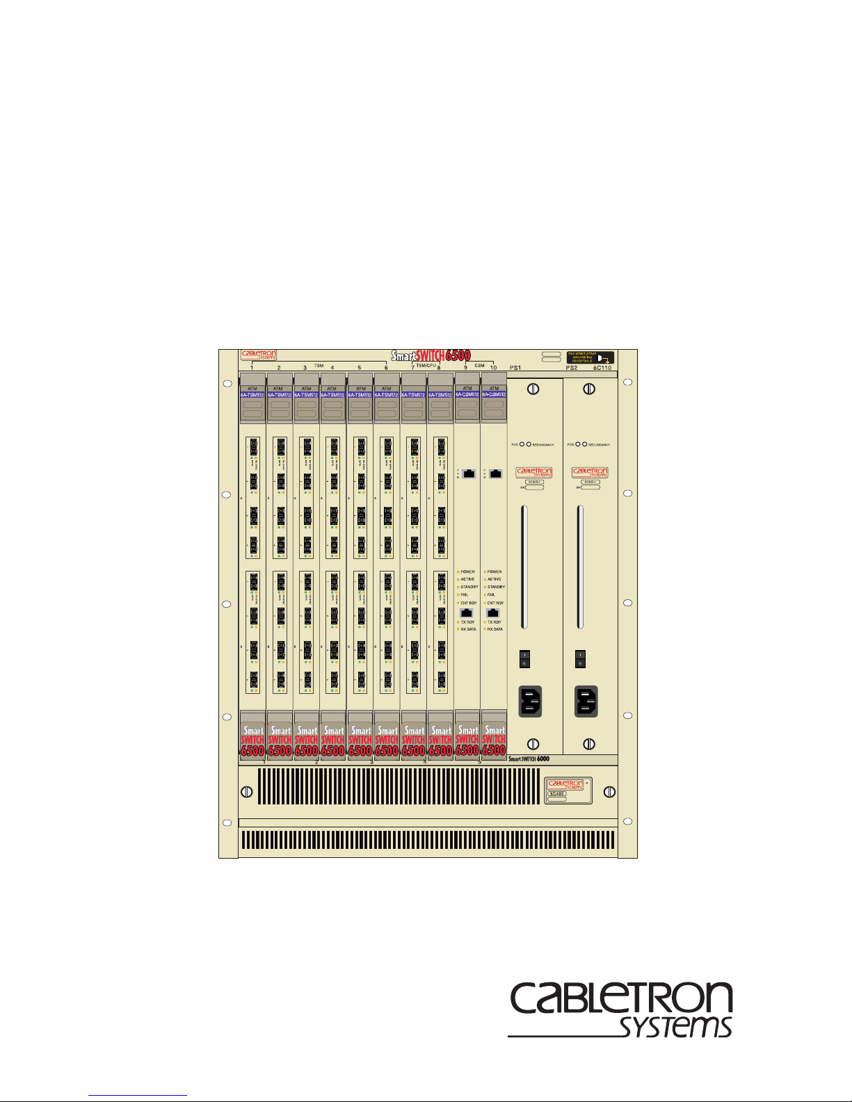
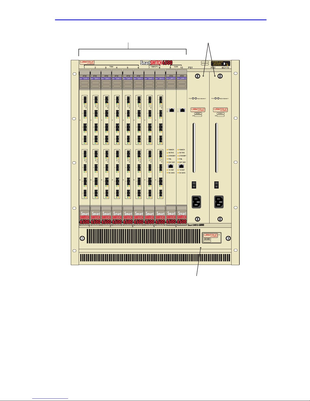
The Cabletron Systems 6C110 chassis design provides ten 1.2-inch slots
that can contain a variety of interface modules. The 19-inch
rackmountable chassis supports redundant power supplies and
LANVIEW diagnostic LEDs. All chassis components (power supplies,
fan tray, and modules) are installed from the front of the chassis for ease
of maintenance. All LED indicators are observable from the front of the
chassis to aid in monitoring network operational status and performing
maintenance. Figure 1-1 illustrates the 6C110 equipped with redundant
power supplies.
1-4 6C110 Overview and Setup Guide
Overview
Interface Modules (10) Redundant Power Supplies (2)
Figure 1-1 The 6C110 Chassis with Redundant Power Supplies
6C110 Overview and Setup Guide 1-5
Fan Tray

Chapter 1:
Introduction
1.7 FEATURES
Redundant Power Supply Modules
The 6C110 supports two power supply modules which reside in the slots
labeled PS1 and PS2.
If the 6C110 is configured with a single power supply module, it
!
CAUTION
must
Installing one ac power supply and one dc power supply in the
same chassis is NOT allowed.
Installing legacy 6C205-2 and 6C205-3 power supplies with
6C210-1 or 6C210-2 power supplies in the same chassis is
NOT allowed.
Each power supply module supports an ac input connector that allows
each power supply to be connected to a separate ac power source.
Cabletron Systems also offers a power supply module that supports a dc
input connector that allows each power supply to be connected to a
separate dc power source. In addition, the power supply modules are
capable of load sharing 50% (+/- 5%) of the total load presented by the
6C110. If one of the power supply modules fails, the other power supply
module supplies the entire load of the chassis without interruption to
network traffic.
be located in slot PS1.
Power Supply LANVIEW LEDs
Each power supply module comes equipped with LEDs for at-a-glance
diagnostics that indicate individual power supply status and overall
chassis redundancy status. Refer to Chapter 2,
Requirements and Specifications
, for a full explanation of the power
Installation
supply LEDs and their definitions.
1-6 6C110 Overview and Setup Guide

Features
Power Supply Status Via Local Management
The 6C110 power supply modules report information to the modules
installed in the chassis regarding the present operating status. This
information includes the following:
•
Power Supply ID (PS1, PS2)
•
Power Supply Status (normal/fault/not installed)
•
Power Supply Redundancy Indication (redundant/not available)
•
Fan Tray Status (normal/fault/not installed)
Refer to the module specific User’s Guide for instructions on how to
access power supply status information via Local Management.
Auto-Ranging Power Supplies
The 6C110 power supply modules automatically adjust to the input
voltage and frequency. No additional adjustments are necessary.
Hot Swapping
To reduce network downtime, the power supply modules are also hot
swappable. This allows for the removal of one power supply without
powering down the chassis and interrupting network traffic.
The 6C110 Cooling System
The 6C110 features a removable fan tray that is accessible from the front
of the unit. This unit is hot swappable, which allows it to be replaced
without powering down the chassis. The fan tray has one LANVIEW
LED located on the front of the unit. This LED indicates the status of the
fan tray (normal or fault). Refer to Chapter 2 for a full description of fan
tray LED states and their definitions.
Rack Mountable Chassis
The 6C110 can be mounted into a standard 19-inch (48.26 cm) equipment
rack. The 6C110 chassis has rackmount brackets b uilt into the chassis for
ease of installation.
6C110 Overview and Setup Guide 1-7
 Loading...