

Cabletron Systems SmartSwitch 6500, SmartSwitch 6C110, SmartSwitch 6500 6C110 Overview And Setup Manual
Page 1
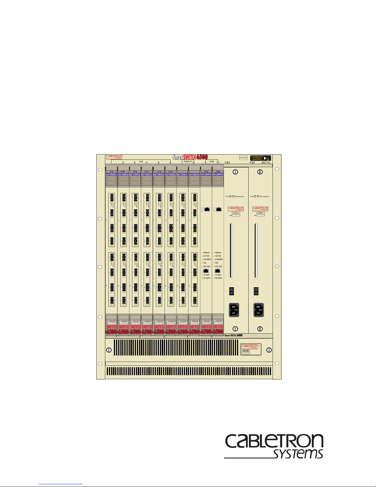
6C110 SmartSwitch 6500
Overview and Setup Guide
9032752-02
Page 2

Page 3

Only qualified personnel should perform installation
procedures.
NOTICE
Cabletron Systems reserves the right to make changes in specifications and other information
contained in this document without prior notice. The reader should in all cases consult Cabletron
Systems to determine whether any such changes have been made.
The hardware, firmware, or software described in this manual is subject to change without notice.
IN NO EVENT SHALL CABLETRON SYSTEMS BE LIABLE FOR ANY INCIDENTAL,
INDIRECT, SPECIAL, OR CONSEQUENTIAL DAMAGES WHATSOEVER (INCLUDING BUT
NOT LIMITED TO LOST PROFITS) ARISING OUT OF OR RELATED TO THIS MANUAL OR
THE INFORMATION CONTAINED IN IT, EVEN IF CABLETRON SYSTEMS HAS BEEN
ADVISED OF, KNOWN, OR SHOULD HAVE KNOWN, THE POSSIBILITY OF SUCH
DAMAGES.
1999 by Cabletron Systems, Inc., P.O. Box 5005, Rochester, NH 03866-5005
All Rights Reserved
Printed in the United States of America
Order Number: 9032752-02 January 1999
Cabletron Systems
Cabletron Systems, Inc.
All other product names mentioned in this manual may be trademarks or registered trademarks of
their respective companies.
is a registered trademark and
SmartSwitch
is a trademark of
FCC NOTICE
This device complies with Part 15 of the FCC rules. Operation is subject to the following two
conditions: (1) this device may not cause harmful interference, and (2) this device must accept any
interference received, including interference that may cause undesired operation.
NOTE:
device, pursuant to Part 15 of the FCC rules. These limits are designed to provide reasonable
protection against harmful interference when the equipment is operated in a commercial environment.
This equipment uses, generates, and can radiate radio frequency energy and if not installed in
accordance with the operator’s manual, may cause harmful interference to radio communications.
Operation of this equipment in a residential area is likely to cause interference in which case the user
will be required to correct the interference at his own expense.
WARNING:
party responsible for compliance could void the user’s authority to operate the equipment.
This equipment has been tested and found to comply with the limits for a Class A digital
Changes or modifications made to this device which are not expressly approv ed by the
6C110 Overview and Setup Guide i
Page 4

Notice
INDUSTRY CANADA NOTICE
This digital apparatus does not exceed the Class A limits for radio noise emissions from digital
apparatus set out in the Radio Interference Regulations of the Canadian Department of
Communications.
Le présent appareil numérique n’émet pas de bruits radioélectriques dépassant les limites applicables
aux appareils numériques de la class A prescrites dans le Règlement sur le brouillage radioélectrique
édicté par le ministère des Communications du Canada.
VCCI NOTICE
This is a Class A product based on the standard of the Voluntary Control Council for Interference by
Information Technology Equipment (VCCI). If this equipment is used in a domestic environment,
radio disturbance may arise. When such trouble occurs, the user may be required to take corrective
actions.
CABLETRON SYSTEMS, INC. PROGRAM LICENSE AGREEMENT
IMPORTANT:
This document is an agreement between you, the end user, and Cabletron Systems, Inc. (“Cabletron”)
that sets forth your rights and obligations with respect to the Cabletron software program (the
“Program”) contained in this package. The Program may be contained in firmware, chips or other
media. BY UTILIZING THE ENCLOSED PRODUCT, YOU ARE AGREEING TO BECOME
BOUND BY THE TERMS OF THIS AGREEMENT, WHICH INCLUDES THE LICENSE AND
THE LIMITATION OF WARRANTY AND DISCLAIMER OF LIABILITY. IF YOU DO NOT
AGREE TO THE TERMS OF THIS AGREEMENT , PR OMPTLY RETURN THE UNUSED
PRODUCT TO THE PLACE OF PURCHASE FOR A FULL REFUND.
Before utilizing this product, carefully read this License Agreement.
ii 6C110 Overview and Setup Guide
Page 5

CABLETRON SOFTWARE PROGRAM LICENSE
Notice
1. LICENSE
package subject to the terms and conditions of this License Agreement.
You may not copy, reproduce or transmit any part of the Program except as permitted by the
Copyright Act of the United States or as authorized in writing by Cabletron.
2. OTHER RESTRICTIONS. You may not reverse engineer, decompile, or disassemble the
Program.
3. APPLICABLE LA W. This License Agreement shall be interpreted and governed under the laws
and in the state and federal courts of New Hampshire. You accept the personal jurisdiction and
venue of the New Hampshire courts.
. You have the right to use only the one (1) copy of the Program provided in this
EXCLUSION OF WARRANTY AND DISCLAIMER OF LIABILITY
1. EXCLUSION OF
writing, Cabletron makes no warranty, expressed or implied, concerning the Program (including
its documentation and media).
CABLETRON DISCLAIMS ALL WARRANTIES, OTHER THAN THOSE SUPPLIED TO
YOU BY CABLETRON IN WRITING, EITHER EXPRESSED OR IMPLIED, INCLUDING
BUT NOT LIMITED TO IMPLIED WARRANTIES OF MERCHANTABILITY AND
FITNESS FOR A PARTICULAR PURPOSE, WITH RESPECT TO THE PROGRAM, THE
ACCOMPANYING WRITTEN MA TERIALS, AND ANY A CCOMPANYING HARDWARE.
WARRANTY. Except as may be specifically provided by Cabletron in
2. NO LIABILITY FOR CONSEQUENTIAL DAMAGES. IN NO EVENT SHALL
CABLETRON OR ITS SUPPLIERS BE LIABLE FOR ANY DAMAGES WHATSOEVER
(INCLUDING, WITHOUT LIMITATION, DAMAGES FOR LOSS OF BUSINESS,
PROFITS, BUSINESS INTERRUPTION, LOSS OF BUSINESS INFORMATION, SPECIAL,
INCIDENTAL, CONSEQUENTIAL, OR RELIANCE DAMAGES, OR OTHER LOSS)
ARISING OUT OF THE USE OR INABILITY TO USE THIS CABLETRON PRODUCT,
EVEN IF CABLETRON HAS BEEN ADVISED OF THE POSSIBILITY OF SUCH
DAMAGES. BECAUSE SOME STATES DO NOT ALLOW THE EXCLUSION OR
LIMITATION OF LIABILITY FOR CONSEQUENTIAL OR INCIDENTAL DAMAGES, OR
ON THE DURATION OR LIMITATION OF IMPLIED WARRANTIES, IN SOME
INSTANCES THE ABOVE LIMITATIONS AND EXCLUSIONS MAY NOT APPLY TO
YOU.
UNITED STATES GOVERNMENT RESTRICTED RIGHTS
The enclosed product (a) was developed solely at private expense; (b) contains “restricted computer
software” submitted with restricted rights in accordance with Section 52227-19 (a) through (d) of the
Commercial Computer Software - Restricted Rights Clause and its successors, and (c) in all respects
is proprietary data belonging to Cabletron and/or its suppliers.
For Department of Defense units, the product is licensed with “Restricted Rights” as defined in the
DoD Supplement to the Federal Acquisition Regulations, Section 52.227-7013 (c) (1) (ii) and its
successors, and use, duplication, disclosure by the Government is subject to restrictions as set forth in
subparagraph (c) (1) (ii) of the Rights in Technical Data and Computer Software clause at
252.227-7013. Cabletron Systems, Inc., 35 Industrial Way, Rochester, New Hampshire 03867-0505.
6C110 Overview and Setup Guide iii
Page 6

Notice
DECLARATION OF CONFORMITY
Application of Council Directive(s):
Manufacturer’s Name:
Manufacturer’ s Address:
European Representative Name:
European Representative Address:
Conformance to Directive(s)/Product Standards:
Equipment Type/Environment:
89/336/EEC
73/23/EEC
Cabletron Systems, Inc.
35 Industrial Way
PO Box 5005
Rochester, NH 03867
Mr. J. Solari
Cabletron Systems Limited
Nexus House, Newbury Business Park
London Road, Newbury
Berkshire RG13 2PZ, England
EC Directive 89/336/EEC
EC Directive 73/23/EEC
EN 55022
EN 50082-1
EN 60950
Networking Equipment, for use in a
Commercial or Light
Environment.
Industrial
We the undersigned, hereby declare, under our sole responsibility, that the equipment packaged
with this notice conforms to the above directives.
Manufacturer Legal Representative in Europe
Mr. Ronald Fotino Mr. J. Solari
___________________________________ ___________________________________
Full Name Full Name
Principal Compliance Engineer Managing Director - E.M.E.A.
___________________________________ ___________________________________
Title Title
Rochester, NH, USA Newbury, Berkshire, England
___________________________________ ___________________________________
Location Location
iv 6C110 Overview and Setup Guide
Page 7

CONTENTS
CHAPTER 1 INTRODUCTION
1.1 Using This Guide.........................................................................1-1
1.2 Structure of This Guide................................................................1-1
1.3 Document Conventions...............................................................1-2
1.4 Using the 6C110 Manual Set.......................................................1-2
1.5 Getting Help.................................................................................1-3
1.6 Overview......................................................................................1-4
1.7 Features ...................................................................................... 1-6
CHAPTER 2 INSTALLATION REQUIREMENTS AND
SPECIFICATIONS
2.1 Site Guidelines ............................................................................ 2-1
2.2 Configuration Guidelines.............................................................2-2
2.3 Operating Specifications..............................................................2-2
2.3.1 Physical Specifications ...................................................2-3
2.3.2 Power Supply Requirements ..........................................2-4
2.4 LEDs............................................................................................2-5
2.4.1 Power Supply LEDs........................................................ 2-5
2.4.2 Fan Tray LED .................................................................2-7
CHAPTER 3 6C110 SETUP
3.1 Unpacking the 6C110..................................................................3-1
3.2 Setting Up the 6C110..................................................................3-2
3.2.1 Installation Order ............................................................3-2
3.3 Installing the Cable Management Bar ......................................... 3-3
3.4 Rack Mounting the 6C110...........................................................3-4
3.5 Attaching the Electrostatic Discharge Wrist Strap.......................3-5
3.6 Removing the Power Bridge Adapter..........................................3-6
3.7 Installing the Power Bridge Adapter............................................3-8
3.8 Power Supply requirements ......................................................3-12
3.9 Installing a Power Supply Module ............................................. 3-13
3.10 Interface Module Slot Requirements.........................................3-16
3.11 Installing 6C110 Interface Modules...........................................3-17
3.12 Powering Up a 6C110 with AC Power Supplies........................3-19
3.13 Powering Up a 6C110 with DC Power Supplies........................3-19
3.13.1 Connecting a 6C205-2 or 6C210-2 to a 48/60 Vdc
Power Source ...............................................................3-21
3.14 Removing and Reinstalling the Fan Tray ..................................3-22
3.14.1 Removing the Fan Tray ................................................3-22
3.14.2 Reinstalling the Fan Tray.............................................. 3-23
6C110 Overview and Setup Guide v
Page 8

Contents
vi 6C110 Overview and Setup Guide
Page 9

CHAPTER 1
INTRODUCTION
Welcome to the Cabletron Systems
and Setup Guide
. This guide explains how to set up and configure the
6C110 SmartSwitch 6500 Overview
Cabletron Systems 6C110 SmartSwitch 6500 chassis.
1.1 USING THIS GUIDE
Read through this guide completely to familiarize yourself with its
contents and to gain an understanding of the features and capabilities of
the 6C110 SmartSwitch 6500. This guide lists the features and options of
the 6C110 SmartSwitch 6500 and explains how to remove and reinstall
the fan tray, and install the power supply(ies), modules and the cable
management bar. A general working knowledge of data communications
networks is helpful when setting up the 6C110 SmartSwitch 6500.
In this document, the 6C110 SmartSwitch 6500 is referred to
NOTE
as either the “6C110” or the “chassis”.
1.2 STRUCTURE OF THIS GUIDE
This guide is organized as follows:
Chapter 1,
how and where to get help, and discusses the features and capabilities of
the 6C110.
Chapter 2,
location requirements that must be met before installing the 6C110 in a
cabinet or rack. This chapter also includes some configuration guidelines,
environmental guidelines, and operating specifications for the 6C110 and
related Power Supply Modules.
Chapter 3,
6C110, removing and reinstalling the fan tray, installing the power
supply(ies), installing a module and module installation requirements,
installing the cable management bar, and powering up the 6C110.
Introduction
, provides manual organizational information,
Installation Requirements and Specifications
6C110 Setup
, contains instructions for rack mounting the
, lists the
6C110 Overview and Setup Guide 1-1
Page 10

Chapter 1:
Introduction
1.3 DOCUMENT CONVENTIONS
Throughout this guide the following symbols are used to call attention to
important information.
Note
symbol. Calls the reader’s attention to any item of
NOTE
information that may be of special importance.
!
CAUTION
Caution
damage to the equipment.
Electrical Hazard Warning
that could result in the presence of an electrical hazard.
symbol. Contains information essential to avoid
symbol. Warns against an action
1.4 USING THE 6C110 MANUAL SET
Other manuals have been developed for the interface modules that can be
installed in the 6C110 chassis. These manuals explain how to install the
modules into the 6C110, how to attach cable segments to the modules,
and how to configure the modules using Local Management after
installation is complete. Specifications for all modules are included in
each manual.
Each manual in this set assumes that the qualified personnel installing the
module has a general working knowledge of data communications
networks and their physical layer components.
1-2 6C110 Overview and Setup Guide
Page 11

Getting Help
1.5 GETTING HELP
For additional support related to this device or document, contact
Cabletron Systems using one of the following methods:
World Wide Web http://www .cabletron.com/
Phone (603) 332-9400
Internet mail [email protected]
FTP ftp://ftp.cabletron.com/
Login
Password
To send comments or suggestions concerning this document, contact the
Cabletron Systems Technical Writing Department via the following
email address:
Make sure to include the document Part Number in the email message.
anonymous
your email address
Before calling Cabletron Systems, have the following information
ready:
•
Your Cabletron Systems service contract number
•
A description of the failure
•
A description of any action(s) already taken to resolve the problem
(e.g., changing mode switches, rebooting the unit, etc.)
•
The serial and revision numbers of all involved Cabletron Systems
products in the network
•
A description of your network environment (layout, cable type, etc.)
•
Network load and frame size at the time of trouble (if known)
•
The device history (i.e., have you returned the device before, is this a
recurring problem, etc.)
•
Any previous Return Material Authorization (RMA) numbers
6C110 Overview and Setup Guide 1-3
Page 12

Chapter 1:
Introduction
1.6 OVERVIEW
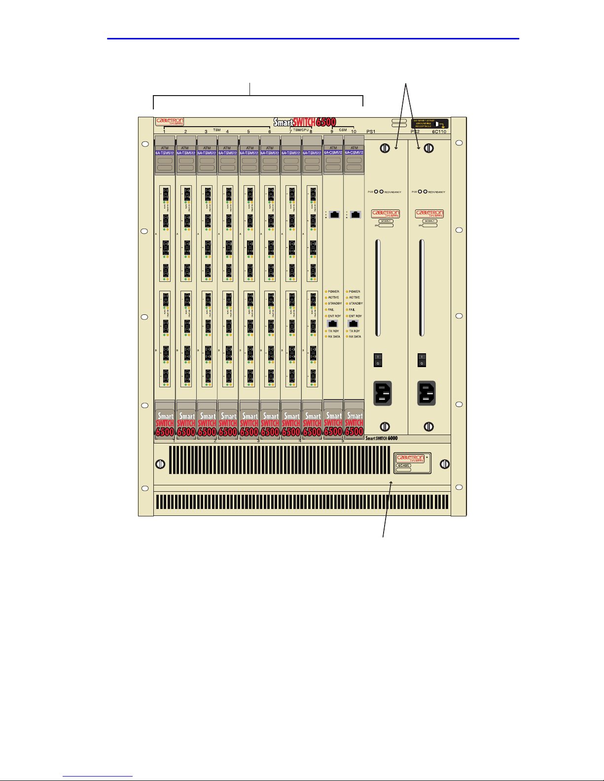
The Cabletron Systems 6C110 chassis design provides ten 1.2-inch slots
that can contain a variety of interface modules. The 19-inch
rackmountable chassis supports redundant power supplies and
LANVIEW diagnostic LEDs. All chassis components (power supplies,
fan tray, and modules) are installed from the front of the chassis for ease
of maintenance. All LED indicators are observable from the front of the
chassis to aid in monitoring network operational status and performing
maintenance. Figure 1-1 illustrates the 6C110 equipped with redundant
power supplies.
1-4 6C110 Overview and Setup Guide
Page 13
Overview
Interface Modules (10) Redundant Power Supplies (2)
Figure 1-1 The 6C110 Chassis with Redundant Power Supplies
6C110 Overview and Setup Guide 1-5
Fan Tray
Page 14

Chapter 1:
Introduction
1.7 FEATURES
Redundant Power Supply Modules
The 6C110 supports two power supply modules which reside in the slots
labeled PS1 and PS2.
If the 6C110 is configured with a single power supply module, it
!
CAUTION
must
Installing one ac power supply and one dc power supply in the
same chassis is NOT allowed.
Installing legacy 6C205-2 and 6C205-3 power supplies with
6C210-1 or 6C210-2 power supplies in the same chassis is
NOT allowed.
Each power supply module supports an ac input connector that allows
each power supply to be connected to a separate ac power source.
Cabletron Systems also offers a power supply module that supports a dc
input connector that allows each power supply to be connected to a
separate dc power source. In addition, the power supply modules are
capable of load sharing 50% (+/- 5%) of the total load presented by the
6C110. If one of the power supply modules fails, the other power supply
module supplies the entire load of the chassis without interruption to
network traffic.
be located in slot PS1.
Power Supply LANVIEW LEDs
Each power supply module comes equipped with LEDs for at-a-glance
diagnostics that indicate individual power supply status and overall
chassis redundancy status. Refer to Chapter 2,
Requirements and Specifications
, for a full explanation of the power
Installation
supply LEDs and their definitions.
1-6 6C110 Overview and Setup Guide
Page 15

Features
Power Supply Status Via Local Management
The 6C110 power supply modules report information to the modules
installed in the chassis regarding the present operating status. This
information includes the following:
•
Power Supply ID (PS1, PS2)
•
Power Supply Status (normal/fault/not installed)
•
Power Supply Redundancy Indication (redundant/not available)
•
Fan Tray Status (normal/fault/not installed)
Refer to the module specific User’s Guide for instructions on how to
access power supply status information via Local Management.
Auto-Ranging Power Supplies
The 6C110 power supply modules automatically adjust to the input
voltage and frequency. No additional adjustments are necessary.
Hot Swapping
To reduce network downtime, the power supply modules are also hot
swappable. This allows for the removal of one power supply without
powering down the chassis and interrupting network traffic.
The 6C110 Cooling System
The 6C110 features a removable fan tray that is accessible from the front
of the unit. This unit is hot swappable, which allows it to be replaced
without powering down the chassis. The fan tray has one LANVIEW
LED located on the front of the unit. This LED indicates the status of the
fan tray (normal or fault). Refer to Chapter 2 for a full description of fan
tray LED states and their definitions.
Rack Mountable Chassis
The 6C110 can be mounted into a standard 19-inch (48.26 cm) equipment
rack. The 6C110 chassis has rackmount brackets b uilt into the chassis for
ease of installation.
6C110 Overview and Setup Guide 1-7
Page 16

Chapter 1:
Introduction
1-8 6C110 Overview and Setup Guide
Page 17

CHAPTER 2
INSTALLATION REQUIREMENTS AND
SPECIFICATIONS
This chapter describes the following:
•
Site guidelines that must be met before installing a 6C110 into a rack
or cabinet
•
6C110 configuration guidelines
•
Operating specifications for the 6C110 enclosure and power supply
modules
Only qualified personnel should install or service this unit.
2.1 SITE GUIDELINES
The following guidelines must be followed when a site is selected for the
6C110. If the guidelines are not followed, unsatisfactory network
performance may result.
•
In order to allow proper cooling within the rack, there must be
3 inches of clearance above the unit and 2 inches of clearance on either
side of the unit.
•
If the 6C110 is to be placed on a shelving unit, the shelf must be able
to support 75 pounds of static weight.
•
If the 6C110 is to be rack mounted, care must be taken to ensure that
the rack used will support the unit and that the rack remains stable with
the 6C110 installed.
•
The 6C110 ac power supplies require a standard three-pronged po wer
receptacle that is located within 6 feet of the site.
•
The temperature of the location must be maintained between 5° and
40°C (41° to 104°F). T emperature changes of greater than 10°C (18°F)
per hour must not occur.
•
The 6C205-2 and 6C210-2 dc power supplies require a 10 AWG solid
copper conducter with #6 ring terminals.
6C110 Overview and Setup Guide 2-1
Page 18

Chapter 2:
Installation Requirements and Specifications
2.2 CONFIGURATION GUIDELINES
The 6C110 has 10 slots that accept interface modules. The slots are
numbered 1 to 10 beginning from the left. There are two additional slots
located on the far right of the chassis that are reserved for power supply
modules. These slots are labeled PS1 and PS2. Cabletron Systems
modules for the 6C110 are equipped with a firmware-based management
tool called Local Management, which provides the capability to configure
the module, and access chassis, power supply, and fan tray information.
These modules are also SNMP compliant to allow remote management
through SNMP software such as the Cabletron Systems SPECTRUM for
Open Systems suite of management products.
2.3 OPERATING SPECIFICATIONS
The following lists the specifications for the 6C110 chassis, 6C405 fan
tray and the 6C205-1, 6C205-2 and 6C205-3 power supplies. Cabletron
Systems reserves the right to change these specifications without notice.
Environment
Operating Temperature: 5°C to 40°C (41°F to 104°F)
Storage Temperature: -30°C to 73°C (-22°F to 164°F)
Operating Relative Humidity: 5% to 90% (non-condensing)
Regulatory Compliance
Safety: UL 1950, CSA C22.2 No. 950,
EN 60950, 73/23/EEC, and IEC 950
Electromagnetic
Compatibility (EMC): FCC Part 15,VCCI V-3, CSA C108.8,
EN 50082-1, 89/336/EEC, AS/NZS 3548
and EN 55022
2-2 6C110 Overview and Setup Guide
Page 19

Operating Specifications
2.3.1 Physical Specifications
The physical specifications for the 6C110 chassis, 6C205-2, 6C205-3,
6C210-1, and 6C210-2 power supply modules and the 6C405 fan tray
module are as follows:
6C110 Chassis
Dimensions: 62.23 H x 44.04 W x 35.56 D (cm)
24.5 H x 17.34 W x 14 D (in)
Weight (with factory
11.81 kg (26 lb)
installed fan tray):
6C205-2 Power Supply
Dimensions: 44.63 H x 6.05 W x 32.77 D (cm)
17.57 H x 2.38 W x 12.9 D (in)
Weight: 3.68 kg (8.1 lb)
6C205-3 Power Supply
Dimensions: 44.63 H x 6.05 W x 32.77 D (cm)
17.57 H x 2.38 W x 12.9 D (in)
Weight: 4.77 kg (10.5 lb)
6C210-1 Power Supply
Dimensions: 44.63 H x 6.05 W x 32.77 D (cm)
Weight: 4.77 kg (10.5 lb)
6C210-2 Power Supply
Dimensions: 44.63 H x 6.05 W x 32.77 D (cm)
Weight: 4.77 kg (10.5 lb)
6C110 Overview and Setup Guide 2-3
17.57 H x 2.38 W x 12.9 D (in)
17.57 H x 2.38 W x 12.9 D (in)
Page 20

Chapter 2:
6C405 Fan Tray
Installation Requirements and Specifications
Dimensions: 6.58 H x 43.64 W x 34.82 D (cm)
2.59 H x 17.18 W x 13.71 D (in)
Weight: 1.59 kg (3.5 lb)
2.3.2 Power Supply Requirements
The power supply requirements for the 6C205-2, 6C205-3, 6C210-1, and
6C210-2 power supply modules are as follows:
6C205-2 DC Power Supply
Input Frequency: NA
Input: (Voltage/Current): 48/60 Vdc, 17 Amps
6C205-3 AC Power Supply
Input Frequency: 50/60 Hz
Input: (Voltage/Current): 100 to 125 Vac, 8 Amps
200 to 250 Vac, 4 Amps
6C210-1 AC Power Supply
Input Frequency: 47/63 Hz
Input: (Voltage/Current): 90 to 125 Vac, 8 Amps
200 to 264 Vac, 4 Amps
6C210-2 DC Power Supply
Input Frequency: NA
Input: (Voltage/Current): 48/60 Vdc, 17 Amps
2-4 6C110 Overview and Setup Guide
Page 21

LEDs
2.4 LEDs
The following subsections describe the functions and definitions of the
LANVIEW LEDs for the power supply module and the fan tray unit for
the 6C110.
All four power supplies available for the 6C110 chassis have
NOTE
the same LEDs.
2.4.1 Power Supply LEDs
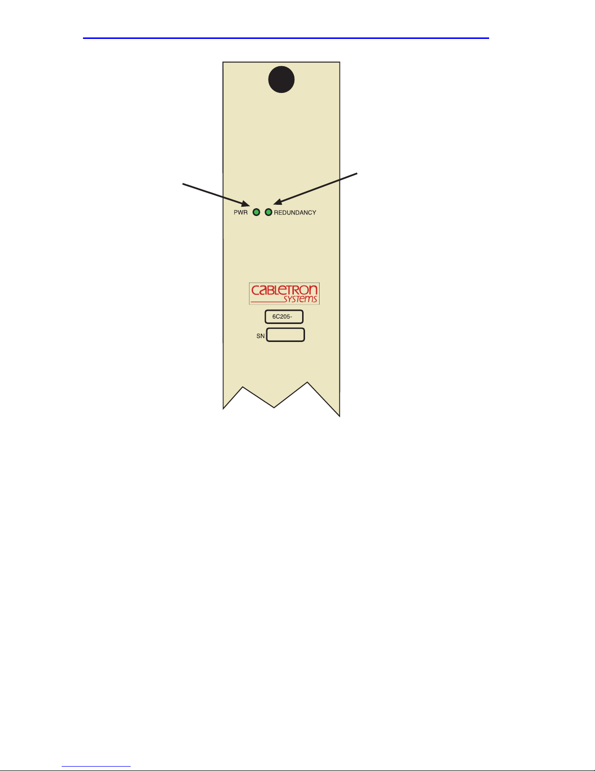
There are two LEDs on the power supply. Table 2-1 describes the
different states of the power supply LEDs and their definitions. Refer to
Figure 2-1 for the location of power supply LEDs.
Table 2-1 Power Supply LED States and Their Definitions
LED Name Color Status
PWR (Power) Green All outputs and inputs of the power supply
are within regulation.
Red Any output or input of the specific power
supply is out of regulation.
REDUNDANCY Green Redundancy is available.
Amber Redundancy is possible, but not a v ailab le
(two power supplies are installed).
Off Redundancy not possible. (One power
supply installed.)
6C110 Overview and Setup Guide 2-5
Page 22
Chapter 2: Installation Requirements and Specifications
PWR LED
Redundancy LED
3
2016_03
Figure 2-1 Power Supply LEDs
2-6 6C110 Overview and Setup Guide
Page 23
LEDs
2.4.2 Fan T ray LED
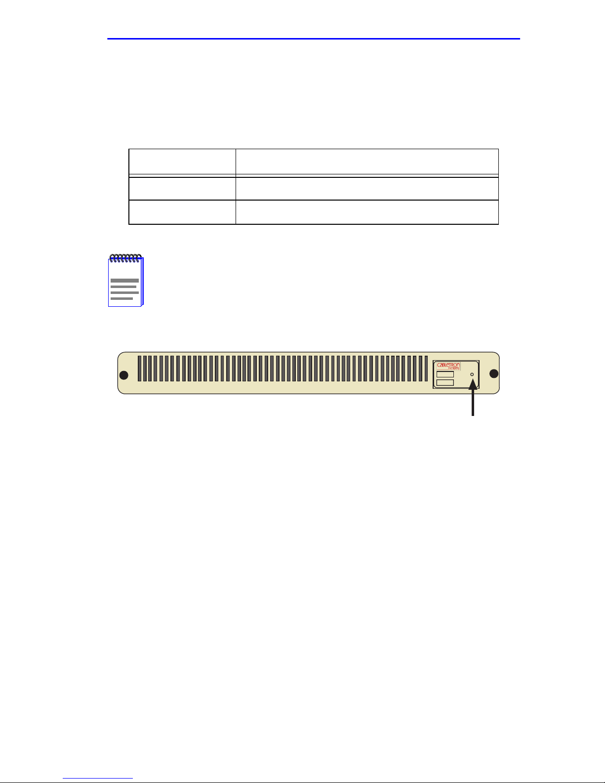
The following table describes the different states of the fan tray LED and
their definitions. Refer to Figure 2-2 for the location of the fan tray LED.
Table 2-2 Fan Tray LED States and Their Definitions
LED Color Status
Green All fans are operating normally.
Red One or more fan failures have occurred.
When the 6C110 is first powered up, the Fan Tray LED will
NOTE
display red briefly, until the fans are operating at the proper
speed.
2016_04
6C405
Fan Tray LED
Figure 2-2 Fan Tray LED
6C110 Overview and Setup Guide 2-7
Page 24

Chapter 2: Installation Requirements and Specifications
2-8 6C110 Overview and Setup Guide
Page 25

CHAPTER 3
6C110 SETUP
This chapter contains instructions on setting up the Cabletron Systems
6C110 chassis. A Phillips screwdriver is needed to install the unit in a
19-inch equipment rack, to install the cable management bar, to secure the
power supply module(s), remove and reinstall the power bridge adapter,
and to remove and reinstall the fan tray. Refer to Chapter 2 for the
guidelines that must be followed to install the 6C110.
A .25-inch hex nut driver is also required to remove and
NOTE
reinstall the power bridge adapter.
Only qualified personnel should install or service this unit.
3.1 UNPACKING THE 6C110
Unpack 6C110 components only as needed. Leave the
NOTE
!
CAUTION
To unpack the 6C110 proceed as follows:
1. Unpack the 6C110 by carefully removing it from the shipping box.
(Save the shipping box and materials in the event the chassis has to be
reshipped.)
2. Remove the chassis from the protective plastic bag. (Save the bag in
the event the unit must be reshipped.)
components in their respective shipping cartons until you are
ready to install that component.
Observe all Electrostatic Discharge (ESD) precautions when
handling sensitive electronic equipment.
3. Examine the 6C110 carefully, checking for damage. If any damage is
noted, DO NOT install the chassis. Contact Cabletron Systems
immediately, (refer to Section 1.5).
6C110 Overview and Setup Guide 3-1
Page 26

Chapter 3: 6C110 Setup
4. Remove the accessory package.
5. Remove the Electrostatic Discharge (ESD) Wrist Strap package.
6. Remove the Console Cable Kit and set aside.
3.2 SETTING UP THE 6C110
The following subsection describes the procedures that must be followed
to complete the installation of the 6C110.
3.2.1 Installation Order
Once a suitable site has been chosen, the 6C110 can be installed. The
chassis can be freestanding or rack mounted.
It is recommended that the 6C110 installation proceed in this order:
1. Install the cable management bar.
2. Mount the chassis to a 19-inch rack or other secure location.
3. Attach the Electrostatic Discharge Wrist Strap.
4. Remove the power bridge adapter, (if applicable).
5. Install the Power Supply Module(s).
6. Install the Interface Modules.
3-2 6C110 Overview and Setup Guide
Page 27
Installing the Cable Management Bar
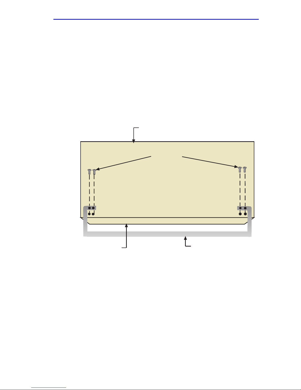
3.3 INSTALLING THE CABLE MANAGEMENT BAR
To install the cable management bar, proceed as follows:
1. Remove the cable management bar from the shipping box. Ensure that
there are four screws inside the bag with the cable management bar.
2. Refer to Figure 3-1. Line up the two holes on each side of the cable
management bar with the two holes located underneath the 6C110,
near the front of the chassis.
3. Using a Phillips screwdriver, securely fasten the 4 screws.
Bottom of Chassis
Screws (4)
Front Panel of Chassis
Figure 3-1 Installing the Cable Management Bar
6C110 Overview and Setup Guide 3-3
Cable Management Bar
2016_05
Page 28
Chapter 3: 6C110 Setup
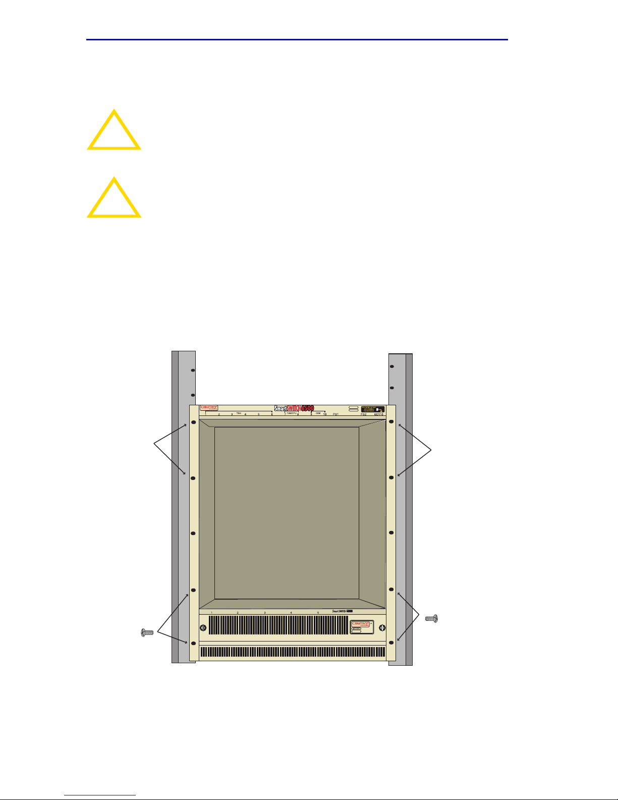
3.4 RACK MOUNTING THE 6C110
The 6C110 can be mounted in a standard 19-inch equipment rack.
If the rack is not secured to the floor, it is recommended that
!
CAUTION
!
CAUTION
Two people may be required to lift the chassis into place.
The chassis is secured with ten screws, five on each side. Using the scre ws
provided with the equipment rack, secure the 6C110 to the rack, starting
with the bottom holes and working up, as shown in Figure 3-2.
the chassis be installed in the bottom half of the rack. This
prevents the rack from being top heavy.
Read Chapter 2 in this manual before completing the following
procedure.
Rack Mounting
Holes (5)
Rack Mounting
Screws (5)
Rack Mounting
Holes (5)
Rack Mounting
Screws (5)
Figure 3-2 Rack Mounting the 6C110
3-4 6C110 Overview and Setup Guide
Page 29
Attaching the Electrostatic Discharge Wrist Strap
3.5 ATTACHING THE ELECTROSTATIC DISCHARGE
WRIST STRAP
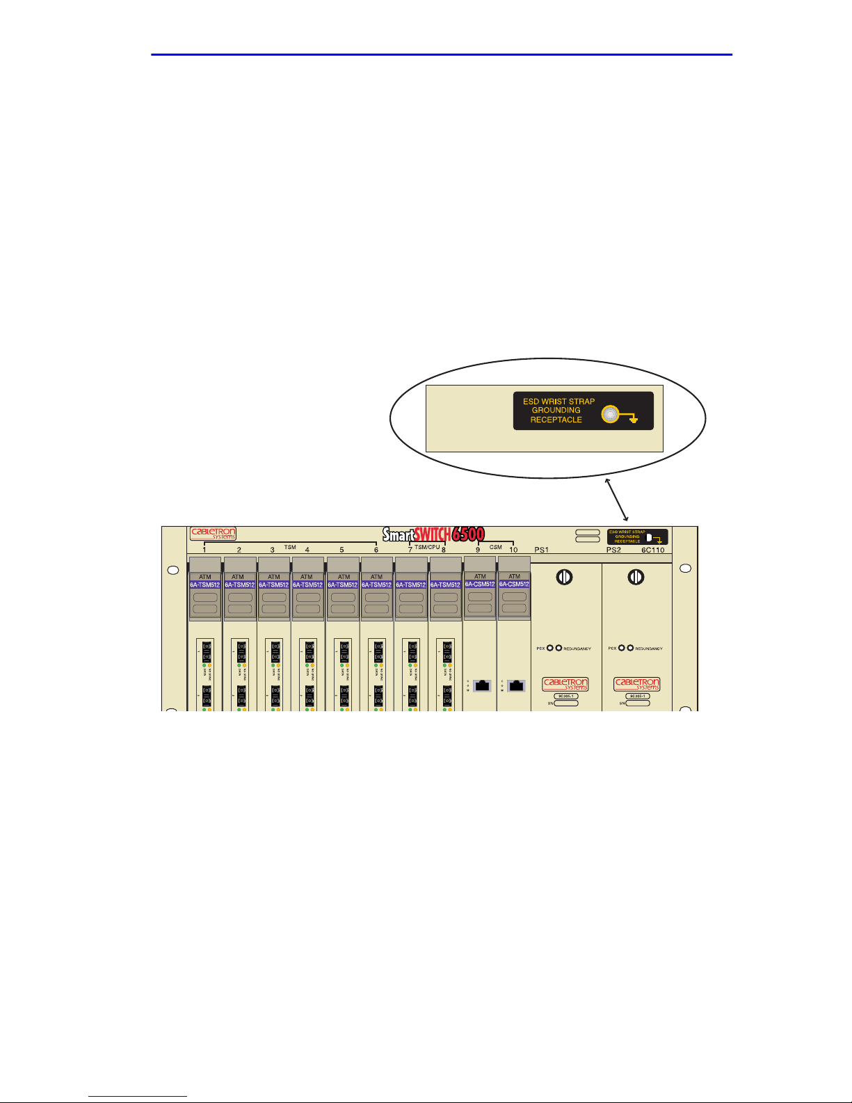
The Electrostatic Discharge (ESD) wrist strap must be attached before
handling the power supplies, fan tray, or modules for the 6C110. In
addition, observe all precautions when handling these modules to prev ent
damage from ESD.
Place the ESD wrist strap on your wrist and plug the other end into the
grounding receptacle, at the top right corner of the chassis, shown in
Figure 3-3.
6C110 Overview and Setup Guide 3-5
Figure 3-3 ESD Grounding Receptacle
Page 30
Chapter 3: 6C110 Setup
3.6 REMOVING THE POWER BRIDGE ADAPTER
This section applies to users that will equip the 6C110 chassis
!
CAUTION
This section provides instructions on removing the power bridge adapter
to allow the 6C110 chassis to support the legacy 6C205-2 or 6C205-3
power supplies. If the 6C210-1 or 6C210-2 power supplies will be used,
DO NOT remove the power bridge adapter.
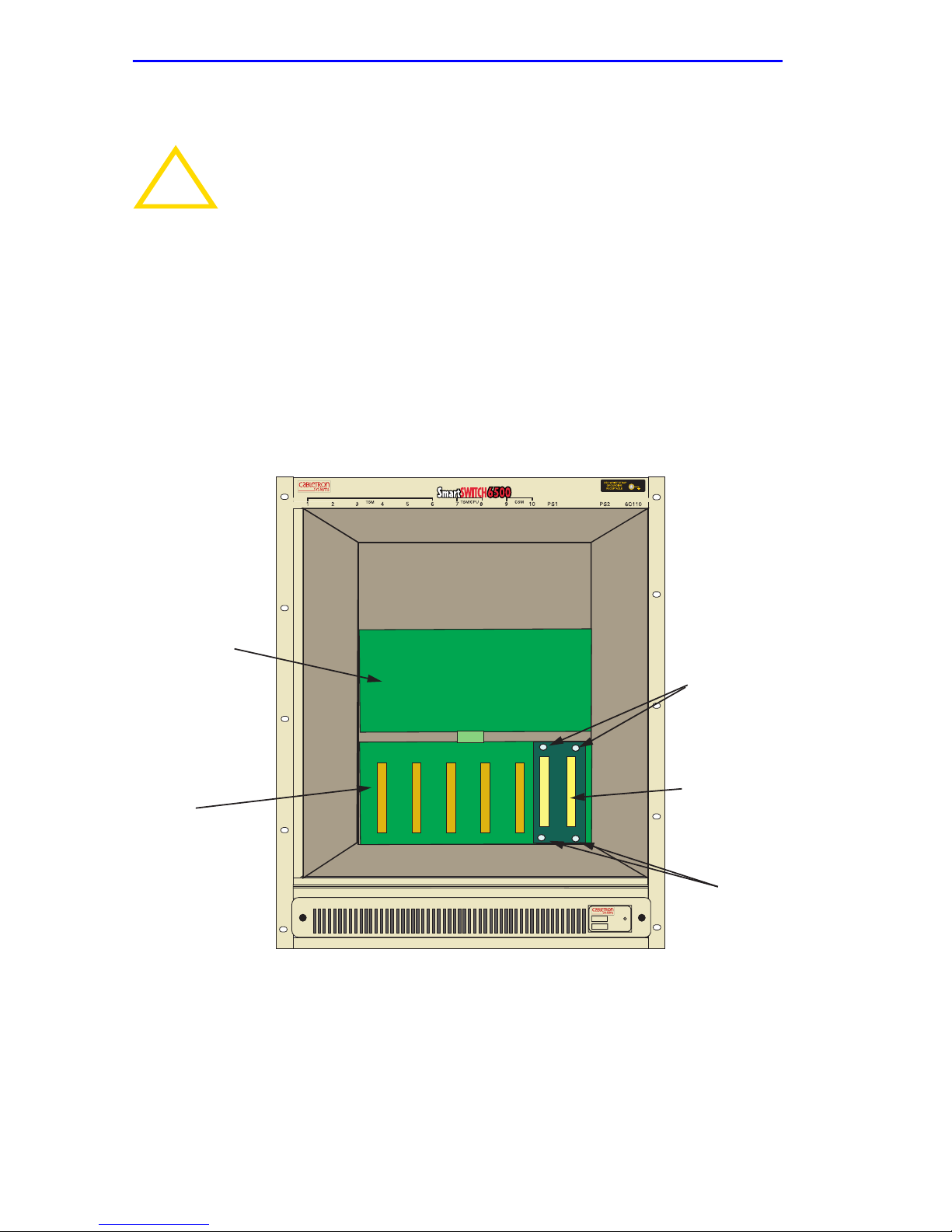
To remove the power bridge adapter, refer to Figure 3-4 and proceed as
follows:
with 6C205-2 or 6C205-3 power supplies ONLY. If 6C210-1 or
6C210-2 power supplies will be used, DO NOT remove the
power bridge adapter.
Upper Backplane
Screws (2)
Power Bridge
Adapter
Lower Backplane
Screws (2)
6C405
Figure 3-4 Removing the Power Bridge Adapter
1. Attach the ESD wrist strap. Refer to Section 3.5 for details.
2. Locate the power bridge adapter that is attached to the right hand side
of the lower backplane as shown in Figure 3-4.
3-6 6C110 Overview and Setup Guide
Page 31
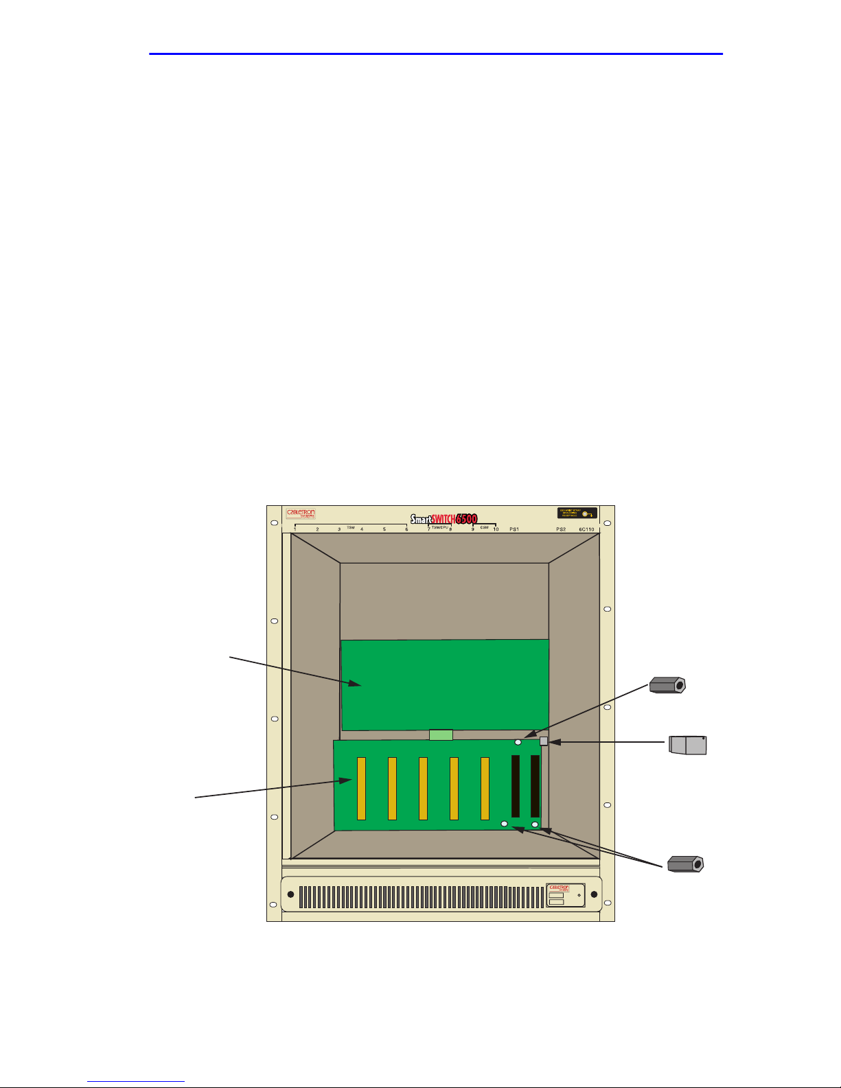
Removing the Power Bridge Adapter
3. Remove the two lower screws and the two upper screws that hold the
power bridge adapter in place. Save the screws.
4. Disconnect the power bridge adapter from the lower backplane.
5. Place the power bridge adapter in a safe place in the event the power
supplies are upgraded to the 6C210-1 or 6C210-2 models.
6. Using a .25-inch hex nut driver, remove the three standoffs that are
attached to the lower backplane. Refer to Figure 3-5.
7. Place the three standoffs in a safe place in the event the power supplies
are upgraded to the 6C210-1 or 6C210-2 models.
8. Locate the rectangular metal clip that is connected to the chassis card
cage. It is located directly to the right of lower backplane. Refer to
Figure 3-5.
9. Remove the support clip by lifting up on the clip. Place the support
clip, and the screw that secured it, in a safe place in the event the power
supplies are upgraded to the 6C210-1 or 6C210-2 models.
Upper Backplane
Standoff
Support Clip
ower Backplane
6C405
Figure 3-5 Removing the Standoffs and Support Clip
Standoffs (2)
10. Reinstall the three screws removed in step 3 into the three receptacles
that formerly held the standoffs.
6C110 Overview and Setup Guide 3-7
Page 32
Chapter 3: 6C110 Setup
3.7 INSTALLING THE POWER BRIDGE ADAPTER
This section applies to users that will equip the 6C110 chassis
!
CAUTION
This section provides instructions on installing the power bridge adapter
to allow the 6C110 chassis to support the 6C210-1 or 6C210-2 power
supplies. If the legacy 6C205-2 or 6C205-3 power supplies will be used
DO NOT install the power bridge adapter.
with 6C210-1 or 6C210-2 power supplies, and the 6C110
chassis has already had the power bridge adapter removed. If
legacy 6C205-2 or 6C205-3 power supplies will be used, DO
NOT install the power bridge adapter.
The three standoffs and the support clip removed from the
chassis in step 6 and step 8 of Section 3.6 are required to
install the power bridge adapter.
To install the power bridge adapter, perform the following steps:
1. Attach the ESD wrist strap. Refer to Section 3.5 for details.
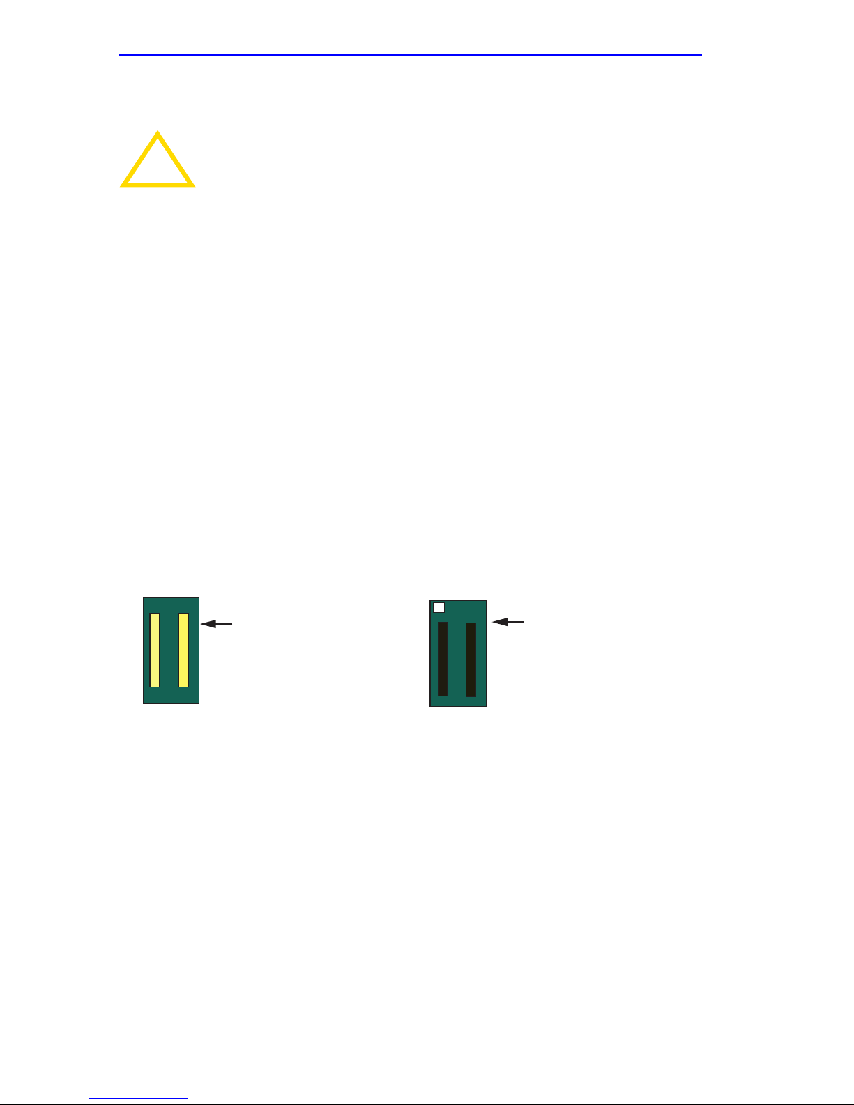
2. Refer to Figure 3-6 to identify the front and rear sides of the power
bridge adapter.
Power Bridge Adapter
(Front, White Connectors)
Figure 3-6 Power Bridge Adapter (Front and Back)
Power Bridge Adapter
(Rear, Black Connectors)
3. Remove the three screws from the lower backplane, as shown in
Figure 3-7.
3-8 6C110 Overview and Setup Guide
Page 33
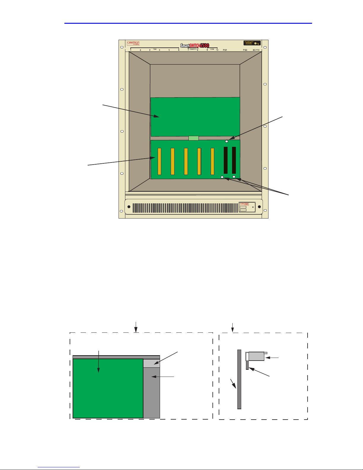
Upper Backplane
Lower Backplane
Installing the Power Bridge Adapter
Screw
Screws(2)
6C405
Figure 3-7 Removing the Screws
4. Using a .25-inch hex nut driver, install the three standoffs into the
holes that formerly held the screws removed in step 3. See Figure 3-9.
5. Install the support clip by sliding the notched end over the rear chassis
card cage, in the space provided next to the upper right hand corner of
the lower backplane. Refer to Figure 3-8 and Figure 3-9.
Front View of Support Clip Installation Location
Upper Right Hand Corner
of Lower Backplane
Chassis Card Cage
Back Panel
of Chassis
Side View of Installation
Back
Panel
of
Chassis
Support Clip
Chassis Card Cage
6C110 Overview and Setup Guide 3-9
Figure 3-8 Installing the Support Clip
Page 34
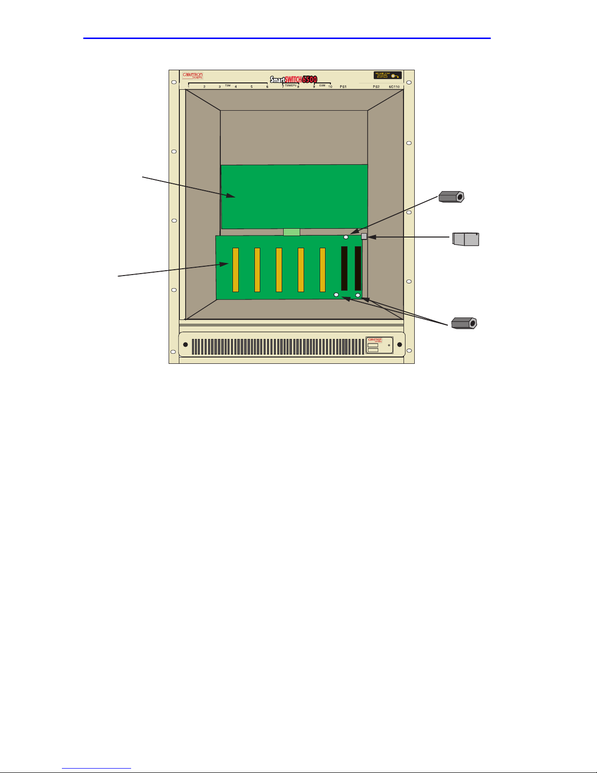
Chapter 3: 6C110 Setup
Upper Backplane
Lower Backplane
Standoff
Support Clip
6C405
Standoffs (2)
Figure 3-9 Installing the Standoffs
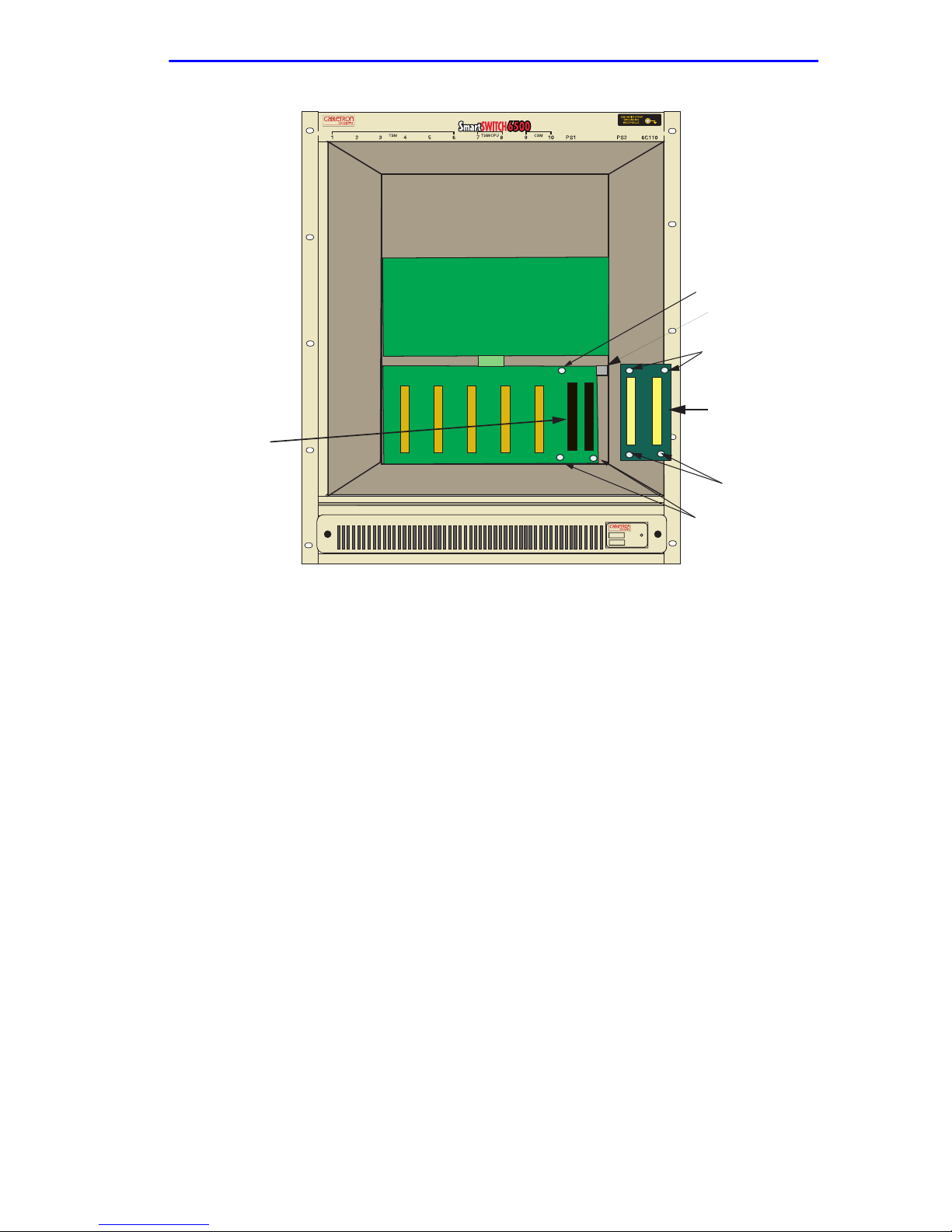
6. Connect the rear (black) power bridge adapter connectors to the lower
backplane connectors of the chassis. Ensure the connectors are firmly
seated together, and the screw holes of the power bridge adapter align
with the standoffs installed in step 4 and the support clip installed in
step 5. See Figure 3-10.
3-10 6C110 Overview and Setup Guide
Page 35
Lower Backplane
Connectors (2)
Installing the Power Bridge Adapter
Standoff
Support Clip
Screw Holes (2)
Power Bridge
Adapter
Screw Holes (2)
6C405
Standoffs (2)
Figure 3-10 Installing the Power Bridge Adapter
7. Attach the power bridge adapter to the lower backplane by fastening
the three screws to the standoffs installed in step 4 and one screw to
the support lip installed in step 5. See Figure 3-10.
8. Installation is complete.
6C110 Overview and Setup Guide 3-11
Page 36

Chapter 3: 6C110 Setup
3.8 POWER SUPPLY REQUIREMENTS
Before installing the power supplies into the 6C110 chassis, ensure the
following power supply requirements are met:
Ensure the requirements outlined in this section are met.
Serious injury or death may occur if these requirements are not
follow ed.
If the chassis will use legacy 6C205-2 or 6C205-3 power supplies, there
may be no more than one CSM, one TSM with a CPU, and 5 TSMs
without CPUs installed in the chassis. Table 3-1 provides additional
details on the interface module slot requirements for the 6C110 chassis.
The name of the power supply (e.g., 6C210-2) ma y be f ound on
NOTE
the front panel of the power supply.
If the chassis is using 6C210-1 or 6C210-2 power supplies, the chassis
can support any type of module configuration.
3-12 6C110 Overview and Setup Guide
Page 37

Installing a Power Supply Module
3.9 INSTALLING A POWER SUPPLY MODULE
Before installing the power supplies, refer to Section 3.8 and
!
CAUTION
You must install at least one power supply in the 6C110 chassis. One
power supply provides sufficient power for most module configurations
but a second power supply can be installed to provide a redundant, load
sharing power source. When two power supplies are installed, the load is
evenly distributed. If one power supply fails for any reason, the second
power supply assumes the load.
Section 3.6 for important information on power supply
requirements for the 6C110 chassis.
Installing legacy 6C205-2 and 6C205-3 power supplies with
6C210-1 or 6C210-2 power supplies in the same chassis is
NOT allowed.
If the 6C110 is configured with a single power supply module, it
!
CAUTION
must be located in slot PS1.
The 6C110 power supplies must be installed in the two slots labeled PS1
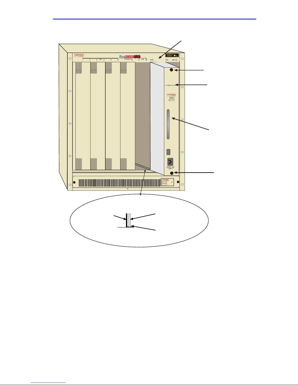
and PS2 on the far right side of the chassis (Figure 3-11). If you intend to
install a single power supply it must be installed in the slot labeled PS1 in
the chassis. A flat blade screwdriver is needed to install the power supply
module(s).
To install the power supply(ies) into the 6C110 chassis, refer to
Figure 3-11 and proceed as follows:
1. Unpack the power supply by removing it from the shipping box and
sliding the two foam end caps off the unit. (Save the shipping box and
materials in the event the unit must be reshipped.)
2. Remove the power supply from its protective plastic bag. (Save the
shipping box and materials in the event the unit must be reshipped.)
3. Examine the power supply carefully, checking for damage. If any
damage is noted, DO NOT install the power supply. Contact Cabletron
Systems immediately.
6C110 Overview and Setup Guide 3-13
Page 38

Chapter 3: 6C110 Setup
4. Slide the power supply module into the slot labeled PS1 as follows:
a. Hold the module by placing one hand on the handle located on the
module front panel and using the other hand to support the body
of the module.
b. With the LED at the top of the power supply module, align the
circuit card of the power supply module with the slotted paths on
the top and bottom of the opening.
Forcing a misaligned module into place can damage the
!
CAUTION
module and/or the chassis backplane.
c. With the power supply inserted into the slotted paths, carefully
slide the module forward until it is connected to the backplane
with the front panel flush with the face of the 6C110. Do not force
the module into place. If significant resistance is encountered
before the front panel is flush, remove and reinsert the power
supply.
d. Secure the power supply to the chassis by using a screwdriver to
tighten the two slotted screws on the top and bottom of the power
supply. For proper chassis grounding, the screws must be properly
tightened.
5. If you are installing a second power supply, remove the blank plate
from the second power supply slot (keep the blank plate in the event
you need to remove the power supply), and repeat steps 1– 4.
3-14 6C110 Overview and Setup Guide
Page 39
Installing a Power Supply Module
Mandatory Power Supply Installed
in Slot PS1
Slotted Screw
Power Supply LEDs
Power Supply Handle
Slotted Screw
6C405
Metal Back-Panel
Circuit Card
Card Guides
2016_09
Figure 3-11 Installing the Power Supply Module(s)
After installation of the power supply modules is completed the 6C110 is
ready to be powered up; however, Cabletron Systems recommends that
installation of all modules for the 6C110 be completed before powering
up the 6C110. Refer to the following sections to complete the installation.
6C110 Overview and Setup Guide 3-15
Page 40

Chapter 3: 6C110 Setup
3.10 INTERFACE MODULE SLOT REQUIREMENTS
The requirements outlined in the following section MUST be
!
CAUTION
The slot numbers located on the top front of the chassis are reserved for
specific SmartSwitch 6500 modules. Table 3-1 provides the slot
requirements.
NOTE
followed for the SmartSwitch 6500 and the installed interface
modules to function properly.
Table 3-1 refers to specific interface modules that are required
for the SmartSwitch 6500 to function properly. Refer to your
interface module documentation set to ensure that the required
modules are at the installation site before installing any new
interface modules.
Table 3-1 Interface Module Slot Requirements
Slot Numbers Interface Module(s) allowed in the slot
Slots 1 through 6 May contain Translation and Scheduling
Modules (TSMs) that DO NOT have CPUs
installed. These slots may also contain any
other Cabletron Systems SmartSwitch 6000
modules (e.g., 6H252-17, 6H123-50, etc.). If
the 6C110 chassis is using 6C205-2 or
6C205-3 power supplies, only five TSMs may
be installed.
Slots 7 and 8 Reserved for TSMs that have a CPU daughter
board installed. The SmartSwitch 6500 chassis
MUST have at least one TSM with a CPU
daughter board in slot 7 or 8. A second TSM
may be installed to provide redundancy. If the
6C110 chassis is using 6C205-2 or 6C205-3
power supplies, only ONE TSM with a CPU
daughter board may be installed.
Slots 9 and 10 Reserved for Cell Storage Modules (CSMs).
3-16 6C110 Overview and Setup Guide
The SmartSwitch 6500 MUST have at least
one CSM installed in slot 9 or 10. A second
CSM may be added to provide redundancy. If
the 6C110 chassis is using 6C205-2 or
6C205-3 power supplies, only ONE CSM may
be installed.
Page 41

Installing 6C110 Interface Modules
3.11 INSTALLING 6C110 INTERFACE MODULES
To install a module, refer to the slot requirements covered in Table 3-1
and proceed as follows:
1. Remove the blank panel covering the slot in which the interface
module will be installed. All other slots must remain covered to ensure
proper airflow and cooling. (Save the blank plate in the event you need
to remove the module.)
2. Carefully remove the module from the shipping box. (Save the box
and packing materials in the event the module must be reshipped.)
3. Locate the ESD wrist strap shipped with the 6C110. Attach the ESD
wrist strap to your wrist and plug the cable from the ESD wrist strap
into the ESD grounding receptacle at the upper right corner of the
6C110.
4. Remove the module from the plastic bag. (Save the bag in the event
the module must be reshipped.) Observe all precautions to prevent
damage from Electrostatic Discharge (ESD).
5. Examine the module for damage. If any damage exists, DO NOT
install the module. Immediately contact Cabletron Systems.
To prevent damaging the backplane connectors in the f ollo wing
!
CAUTION
NOTE
step, take care that the module slides in straight and properly
engages the backplane connectors.
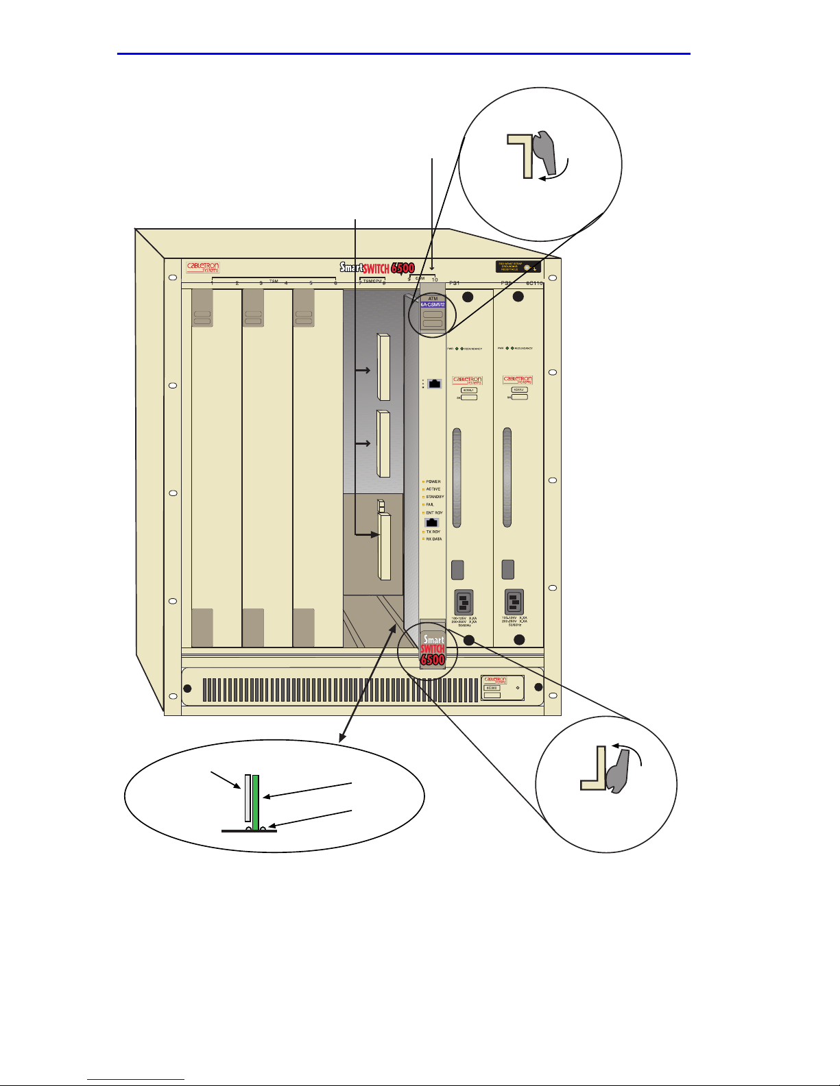
In the following step ensure that the top plastic locking tab lines
up with the desired slot number located on the front panel of
the chassis. Refer to Figure 3-12.
6. Locate the slot guides that line up with the number of the slot in which
the module will be installed. Install the interface module in the chassis
by aligning the module circuit card between the upper and lower metal
rail guides of the desired slot, sliding it into the chassis, and locking
down the top and bottom plastic locking tabs, as shown in Figure 3-12.
Take care that the interface module slides in straight and properly
engages the backplane connectors.
6C110 Overview and Setup Guide 3-17
Page 42
Chapter 3: 6C110 Setup
Slot Number
Backplane
Connectors
Plastic Locking Tab
Metal Back-Panel
Figure 3-12 Installing a Module
3-18 6C110 Overview and Setup Guide
Circuit Card
Card Guides
2159-01
Plastic
Locking Tab
2361-02
Page 43

Powering Up a 6C110 with AC Power Supplies
3.12 POWERING UP A 6C110 WITH AC POWER
SUPPLIES
To power up a 6C110 with ac power supply modules proceed as follows:
If two power supplies are installed, repeat the following
NOTE
1. Plug one end of the power cord (supplied with the power supply) into
the ac power socket on the bottom of the power supply.
2. Plug the other end of the power cord into an ac receptacle. Turn on the
power supply using the switch located above the power socket.
3. Ensure that the Power LED is green.
procedure for each supply.
4. Ensure that all fans in the fan tray unit are operating properly when
power is received from the power supply modules (fan tray LED will
be green).
If you experience any problems during the installation of the 6C110,
contact Cabletron Systems for assistance.
3.13 POWERING UP A 6C110 WITH DC POWER
SUPPLIES
This section provides information on how to connect the 6C205-2 dc and
6C210-2 dc power supplies to 48 or 60 Vdc (48/60 Vdc) power sources.
The 6C205-2 and 6C210-2 are installed and function the same as the ac
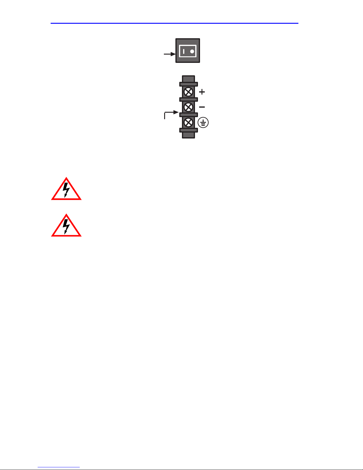
power supplies for the 6C110. The 6C205-2 power supply has an on/off
switch and an input power strip, and is rated at 510 watts. The 6C210-2
power supply has an on/of f switch and an input power strip, and is rated at
800 watts. The on/of f power switches and input po wer strips are similar to
the ones shown in Figure 3-13.
The on/off switch of the 6C205-2 and 6C210-2 power supplies
NOTE
6C110 Overview and Setup Guide 3-19
contains a 30 Amp circuit breaker.
Page 44
Chapter 3: 6C110 Setup
ON/OFF
DC Input Power Strip
2016_99
Figure 3-13 Power Supply DC ON/OFF Switch and DC Input Power Strip
ONLY QUALIFIED PERSONNEL SHOULD PERFORM THESE
INSTALLATION PROCEDURES.
TO REDUCE THE RISK OF ELECTRIC SHOCK OR ENERGY
HAZARDS:
• CONNECT TO A RELIABLY GROUNDED 48/60 VDC
SELV SOURCE.
• ENSURE THE BRANCH CIRCUIT OVERCURRENT
PROTECTION IS RATED AT A MINIMUM
OF 25 A.
• USE 10 AWG SOLID COPPER CONDUCTORS ONLY.
• ENSURE THAT A READILY ACCESSIBLE
DISCONNECT DEVICE THAT IS SUITABLY
APPROVED AND RATED, IS INCORPORATED IN
THE FIELD WIRING.
TO BE INSTALLED IN A RESTRICTED ACCESS AREA IN
ACCORDANCE WITH THE NEC OR THE AUTHORITY
HAVING JURISDICTION.
DC Power Supply Requirement for Each Supply
Each dc power supply input requires either a 48 Vdc or 60 Vdc power
source, rated at a minimum of 17 Amps.
3-20 6C110 Overview and Setup Guide
Page 45
Powering Up a 6C110 with DC Power Supplies
Installation Requirement
Each dc power supply input requires either a 48 Vdc or 60 Vdc power
source supplied by three 10 AWG (American Wire Gauge) copper wires.
These wires must be terminated with either ring or spade terminals that
accept a #6 screw.
3.13.1 Connecting a 6C205-2 or 6C210-2 to a 48/60 Vdc
Power Source
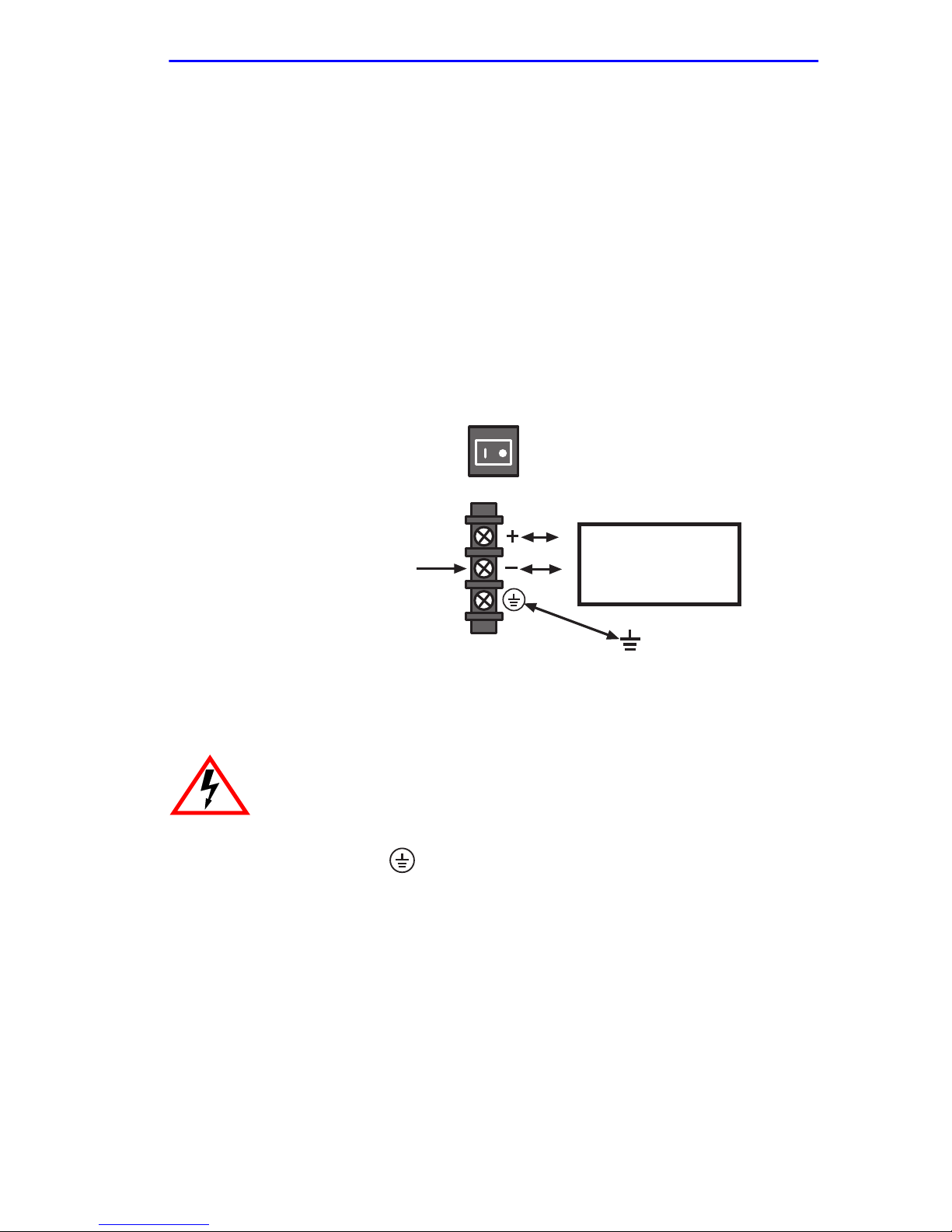
T o connect the 6C205-2 or 6C210-2 to a 48/60 Vdc power source, f ace the
front of the power supply, then refer to Figure 3-14 and proceed as
follows:
ON/OFF
+
48 or 60 Vdc
DC Input Power Strip
2016_98
Figure 3-14 48/60 Vdc Power Supply Connections
To prevent injury or damage to the equipment, remove power
from a 48/60 Vdc power source before proceeding with the
following steps.
-
Power Source
Earth
Ground
1. Connect the ground terminal of the dc input power strip to an
appropriate earth ground.
2. Refer to Figure 3-14 for the proper connections to a 48/60 Vdc power
source. Then connect the output leads of the 48/60 Vdc power source
being used to the negative (-) and positive (+) terminals on the dc input
power strip.
3. Repeat steps 1 and 2, if applicable, to connect a 48/60 Vdc power
source to a second dc power supply installed in the chassis.
4. Restore power to the 48/60 Vdc power sources.
6C110 Overview and Setup Guide 3-21
Page 46

Chapter 3: 6C110 Setup
5. Press the on/off power switch of each power switch to on.
The 6C205-2 and 6C210-2 sound an audible alarm if there is a
NOTE
polarity reversal. If the alarm sounds, turn off the 48/60 Vdc
power source to that power supply. Then reverse the positive
and negative leads to the dc input power strip of that power
supply. Restore power from the 48/60 Vdc power source. If the
alarm sounds again, press the power switch to off and call
Cabletron Systems. Refer to Section 1.5.
If you experience any problems during the installation of the 6C110,
contact Cabletron Systems for assistance.
3.14 REMOVING AND REINSTALLING THE FAN TRAY
The 6C110 is equipped at the factory with a removable fan tray that
allows for easy periodic cleaning and/or replacement if a problem occurs
with fan operation. A flat blade screwdriver is needed to remove and
reinstall the fan tray. To remove and reinstall the fan tray in the 6C110,
refer to Section 3.14.1 and Section 3.14.2.
The fan tray is hot swappable; however, the chassis must not
!
CAUTION
be run without the fan tray for extended periods of time, as it
will quickly overheat.
3.14.1 Removing the Fan Tray
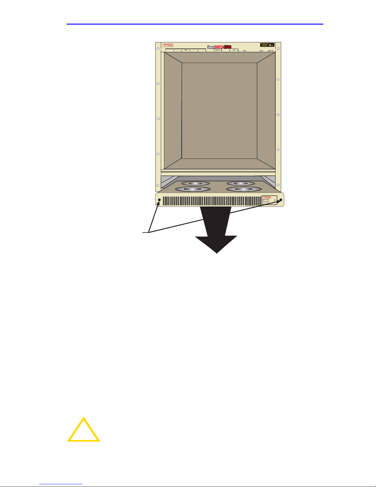
To remove the fan tray, refer to Figure 3-15 and proceed as follows:
1. Locate the ESD wrist strap shipped with the 6C110. Attach the ESD
wrist strap to your wrist and plug the cable from the ESD wrist strap
into the ESD grounding receptacle at the upper right corner of the
6C110.
2. Use a flat blade screwdriver to loosen the slotted screws located on
either side of the fan tray.
3. Slowly slide the fan tray out of its slot in the bottom of the chassis.
3-22 6C110 Overview and Setup Guide
Page 47
Removing and Reinstalling the Fan Tray
6C405
Slotted Screws (2)
2016_20
Figure 3-15 Removing the Fan Tray
3.14.2 Reinstalling the Fan Tray
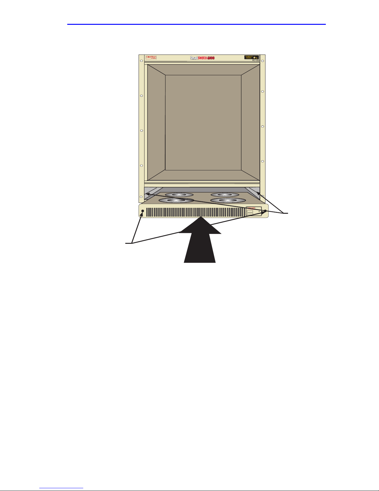
To reinstall the fan tray, refer to Figure 3-16 and proceed as follows:
1. Locate the ESD wrist strap shipped with the 6C110. Attach the ESD
wrist strap to your wrist and plug the cable from the ESD wrist strap
into the ESD grounding receptacle at the upper right corner of the
6C110.
2. Hold the sides of the fan tray.
3. Line up the rails on each side of the fan tray with the slot guides on the
chassis.
In the following step ensure that you do not force the fan tray
!
CAUTION
6C110 Overview and Setup Guide 3-23
into place, as it may damage the unit.
Page 48

Chapter 3: 6C110 Setup
4. Slide the fan tray forward until the faceplate of the tray is flush with
the face of the 6C110. If there is any strong resistance, remove the fan
tray and reinsert it.
5. Once the tray is in place, tighten the slotted screws with a flat blade
screwdriver to secure the tray to the 6C110.
6. When the 6C110 is ready to be powered on, observe the LED on the
front of the fan tray. This LED should be red for a moment after the
power switch is turned on, and then change to green to indicate that all
fans are operating properly. If this LED remains red, it indicates that
one or more of the fans are not operating at the proper speed. Check
the fan tray to ensure that nothing is interfering with the movement of
the fans; also, check to make sure nothing is blocking the air vents on
the chassis or the fan tray. If the problem cannot be located, call
Cabletron Systems for assistance.
!
CAUTION
The fan tray is hot swappable; however, the chassis must not
be run without the fan tray for extended periods of time, as it
will quickly overheat.
3-24 6C110 Overview and Setup Guide
Page 49
Removing and Reinstalling the Fan Tray
1
2345
PS1
PS2
Slotted Screws (2)
6C405
2016_08
Figure 3-16 Reinstalling the Fan Tray
Slot Guides
6C110 Overview and Setup Guide 3-25
Page 50

Chapter 3: 6C110 Setup
3-26 6C110 Overview and Setup Guide
 Loading...