

Cabletron Systems 1088, SM-CSI1076, SmartSwitch 6000 SM-CSI1076, SmartSwitch 6000 SM-CSI1082, SmartSwitch 6000 SM-CSI1088 User Manual
SmartSwitch 6000

Restricted Rights Notice
(Applicable to licenses to the United States Government only.)
1. Use, duplication, or disclosure by the Government is subject to restrictions as
set forth in subparagraph (c) (1) (ii) of the Rights in Technical Data and
Computer Software clause at DFARS 252.227-7013.
Cabletron Systems, Inc., 35 Industrial Way, Rochester, New Hampshire 03866.
2. (a) This computer software is submitted with restricted rights.It may not be
used, reproduced, or disclosed by the Government except as provided in
paragraph (b) ofthisNotice or as otherwise expressly statedinthe contract.
(b) This computer software may be:
(1) Used or copied for use in or with t he computer or computers for which
it was acquired, including use at any Government installation to which
such computer or com puters may be transferred;
(2) Used or copied for use in a backup computer if anycomputer forwhich
it was acquired is inoperative;
(3) Reproduced for safekeeping (archives) or backup purposes;
(4) Modified, adapted, orcombined with othercomputer software,provided
that the modified, combined, or adapted portions of the derivative
software incorporating restricted computer software are made subject
to the same restricted rights;
(5) Disclosed to and reproduced for use by support service contractors in
accordance with subparagraphs (b ) (1) through (4) of this clause,
provided the Government mak e s such disclosure or reproduction
subject to these restricted right s; and
(6) Used or copied for use in or transferred to a replacement computer.
(c) Notwithstanding the foregoing, if this computer software is published
copyrighted computer software, it i s licensed to the Government, without
disclosure prohibitions,withthe minimum rights setforthin paragraph (b) of
this clause.
(d) Any other right s or limitations regarding the use, duplication, or disclosure
of this computer software are to be expressly stated in, or incorporated in,
the contract.
(e) This Notice shallbemarkedonanyreproduction of this computer software, in
whole or in part.

Contents
Error Source (Selection).....................................15
Fast Ethernet Operation (Check) .......................15
Fast Ethernet Operational Mode (Check)...........15
FDDI Operation (Check).....................................16
Firmware (Upgrade)...........................................16
Model a SmartSwitch 6000 ................................16
Performance Statistics (View) ............................16
Port Operation (Monitor).....................................16
Port Operational Mode (Set) ..............................16
Ports (Configure)................................................16
Power Supply Status (Check) ............................16
Remote Hardware Received Tech (Check)........16
Repeater Frame and Error Stats (View).............16
Repeater Frame Size and Protocols (View).......16
Repeater Performance (Check) .........................16
Repeater Port Status (Check)............................16
Repeater Port Speed (Set) .................................17
Repeater Port Condition Display (Change)........17
Topology (Check)...............................................17
Traps (Set Up)....................................................17
Virtual Channel Operation (Check) ....................17
PERFORMANCE VIEWS 18
Device Performance View.............................................19
Bridging Performance View ..........................................19
Interface Performance View..........................................19

Supported Applications............................................. 40
Fast Ethernet Application View .................................... 40
Fast Ethernet Port Table........................................... 40
ATM Client Application................................................. 41
ATM Client Application VCL Table............................ 42
Virtual Channel Link View.........................................44
CsRipEnetRpt Repeater Application ......................... 46
Download Application................................................... 46
CONFIGURATION VIEWS 47
Device Configuration View ........................................... 47
Interface Configuration Table.................................... 48
Port Configuration - CSIIfPort View.............................. 49
FddiMAC Device Configuration View ........................... 49
Station Configuration ................................................ 49
SMT Information ....................................................... 52
ATM Client Configuration View .................................... 52
Fast Ethernet Configuration View................................. 54
Operational Mode ..................................................... 54
Advertised Ability ...................................................... 55
Received Technology............................................... 55
Repeater Configuration View ....................................... 56
Repeater Management............................................. 56
Trap Configuration.................................................... 57
Alarm Configuration.................................................. 57
Error Source.............................................................. 58
Ethernet Based Configuration ...................................... 58
MODEL INFORMATION VIEW 60


Introduction
and navigation techniques, refer to the
documentation listed under Required Reading.
Required Reading
To use this documentation effectively, you must
be familiar with the information covered by the
other SPECTRUM online documentation topics
list below:
• Getting Started with SPECTRUM for
Operators
• Getting Started with SPECTRUM for
Administrators
• How to Manage Your Network with
SPECTRUM
• SPECTRUM Views
• SPECTRUM Menus
• SPECTRUM Icons

Networking Characteristics
The SmartSwitch 6000 is designed with a fully
distributed switching architecture within each
module, which allows the modules to be managed
as a single entity, with a single module acting as a
proxy agent for the chassis, see odesManagement
Modes (page 9).
The SmartSwitch 6000 provides port mirroring,
port trunking, broadcast control, Quality of
Service (QoS), VLAN, and topology protocol, all in
either traditional 802.1d mode or Cabletron’s
SecureFast mode. Optional RMON support is also
available.
The SmartSwitch 6000 can provide the following
port connectivities:
• Switched Ethernet
• Switched Fast Ethernet
• MicroLAN Ethernet or Fast Ethernet
• Gigabit Ethernet uplinks
• OC-3, DS-3/E-3, and OC-12 switched ATM

Standalone Mode
In this mode, each installed module provides its
own management functions. You configure all of
the modules in the chassis to Standalone mode
and assign separate IP addresses for each
module. SPECTRUM management is through the
representative Device icons created for each
module during discovery and modeling.
Mixed Mode
This mode provides a method of operationally
isolating a module (or modules) for security
purposes. You set an IP address for the chassis
and configure all non-secure modules in
Distributed mode. The secure module gets its own
IP address and is configured in Standalone mode.
SPECTRUM management is through the
representative Device icons created.
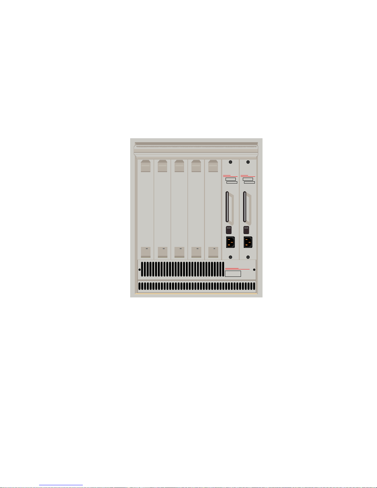
Figure 1: SmartSwitch 6000 Chassis
CaBLeTROn
SYSTeMS
6C105
Smart
SWITCH
6000
Smart
SWITCH
6000
Smart
SWITCH
6000
Smart
SWITCH
6000
Smart
SWITCH
6000
100 • 125 VAC
200 • 250 VAC
50 • 60 Hz
CaBLeTROn
SYSTeMS
PDK0 0 REDUNDANCY
6C205-1
B0096520019
SN
100 • 125 VAC
200 • 250 VAC
50 • 60 Hz
CaBLeTROn
SYSTeMS
PDK0 0 REDUNDANCY
6C205-1
B0096520019
SN

6E Ethernet Modules
These modules provide the front panel ports and
interface uplink connectivities listed in Table 2.
Table 2: 6E Series Connectivities
Module Connectivity
6E122-26 24 10BaseT ports via RJ45 s pl us two F EPIM
slots
6E132-25 24 10BaseT ports via RJ45s plus one HSIM
slot
6E123-26 48 10BaseT po rts via two telc os plus two
FEPIM slots
6E133-25 24 10BaseT po rts via two telc os plus one
HSIM slot
6E128-26 24 ports via MMF STs plus two FEPIM slots
6E129-26 24 ports via SMF STs plus two FEPIM slots
6E138-25 24 ports via MMF STs plus one HSIM slot
6E139-25 24 ports via SMF STs plus one HSIM slot
6E123-50 48 MicroLan 10BaseT ports via RJ21 telcos
plus 2 FEPIM slots
6E133-49 48 MicroLan 10BaseT ports via RJ21 telcos
plus one HSIM slot
6E233-49 48 Ethernet ports via RJ21 telcos plus one
HSIM slot

6M146-04 Carrier Module
This is a SmartSwitch carrier uplink module. It
provides two HSIM slots and two FEPIM slots.
The SPECTRUM Model
SPECTRUM lets you model and manage
individual modules or groups of modules on a
network installed in, or connected to, the chassis.
The models provide access to the information
needed to manage the modules, including
software emulation of the actual module
6H133-37 Three RJ21 telcos (12 ports each in any
combination of auto-negotiating 10Ba seT
Ethernet or 100BaseT Fast Ethernet) plus
one HSIM slot
6H203-24 24 port 10/100 switching module via two
RJ21 ports
6H253-13 12 port 10/100 switching module via one
RJ21 connector
6H258-17 16 MMF ports via MT-RJ connectors and
one VHSIM slot
6H262-18 6 fixed RJ45 ports and 2 FEPIM slots
Table 3: 6H Series Connectivities
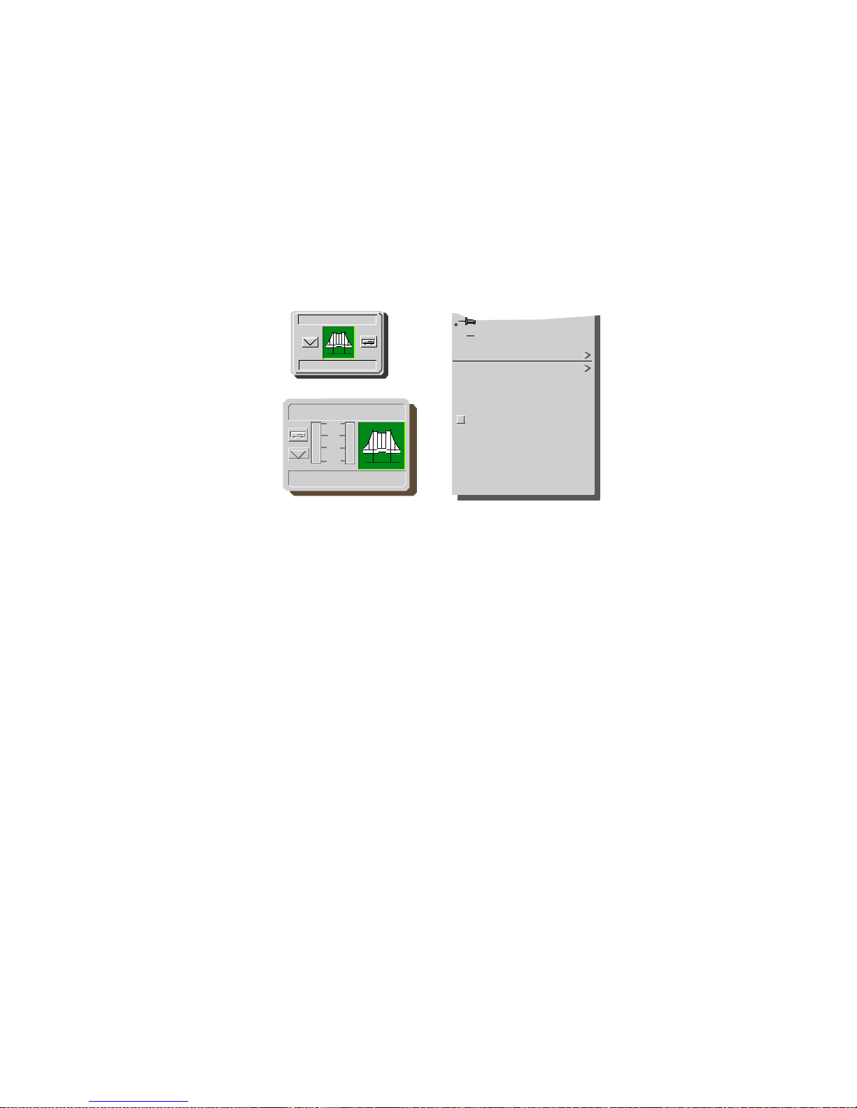
Figure 2: Device Icons
Close Ctrl +c
Navigate
Zoom
Device
DevTop
Application
Acknowledge
Flash Green Enabled
Configuration
Model Information
Primary Application
NetWideApp
10
1
.1
.01
IP Address
6H203_24
IP Address
6H203_24

• ATM Client Configuration View (page 52)
(available with optional HSIM or FEPIM)
• Fast Ethernet Configuration View (page 54)
• Repeater Configuration View (page 56)
• Ethernet Based Configuration (page
58)(available for GPIM models)
• Model Information View (page 60)

Tasks
Chassis Information (View)
• Chassis Device View (page 21)
Concentrator Status (Check)
• FddiMAC Device Configuration View (page 49)
Error Source (Selection)
• Error Source (page 58)
Fast Ethernet Operation (Check)
• Fast Ethernet Configuration View (page 54)
• Fast Ethernet Application View (page 40)
• Operational Mode (page 54)
• Advertised Ability (page 55)
• Received Technology (page 55)
• Ethernet Based Configuration (page 58)
Fast Ethernet Operational Mode (Check)
• Fast Ethernet Configuration View (page 54)

Port Operational Mode (Set)
• Interface Labels (page 25)
Ports (Configure)
• Fast Ethernet Configuration View (page 54)
• Ethernet Based Configuration (page 58)
Power Supply Status (Check)
• Chassis Information (page 29)
Remote Hardware Received Tech (Check)
• Received Technology (page 55)
Repeater Frame and Error Stats (View)
• Repeater Frame & Error Breakdown View
(page 27)
Repeater Frame Size and Protocols (View)
• Repeater Frame Size & Protocols View (page
27)
Repeater Performance (Check)
• Repeater Label Icon Subviews(Table 8)
Repeater Port Status (Check)
• Repeater Configuration View (page 56)
• CsRipEnetRpt Repeater Application (page 46)

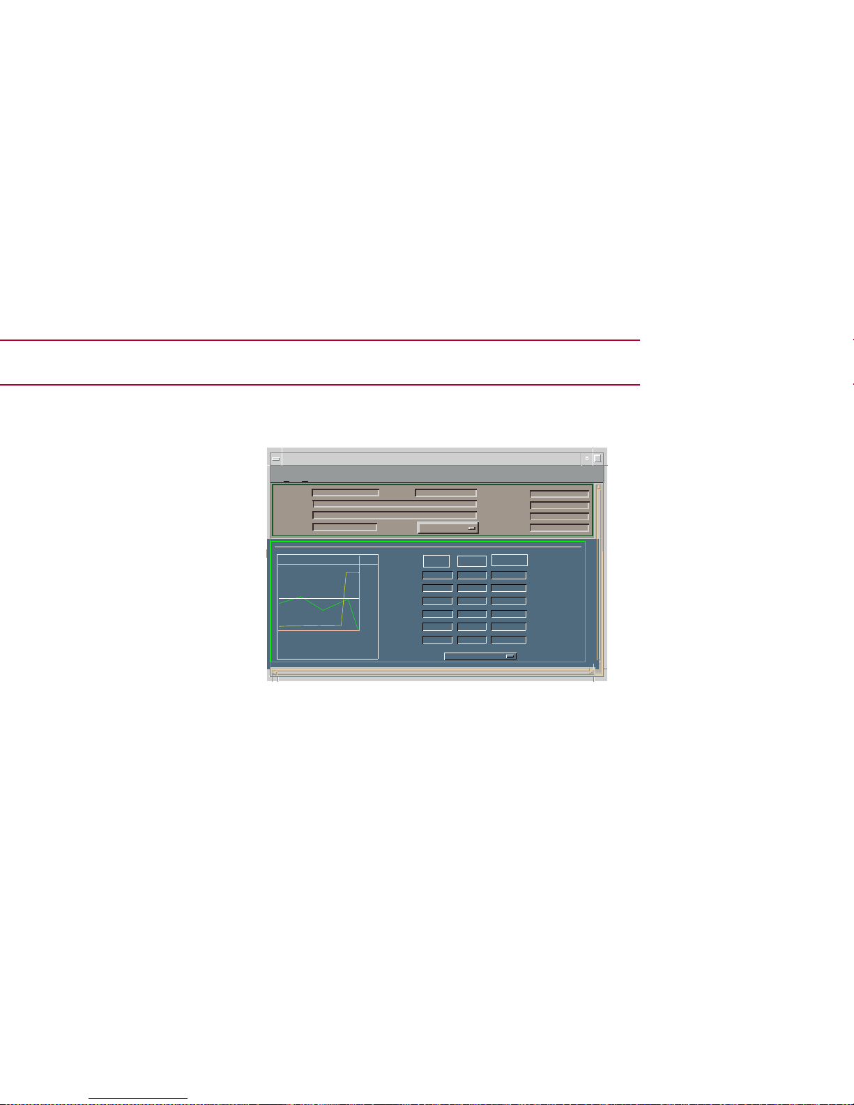
Performance Views
Figure 3: Device Performance View
*
File View
H
elp
IP address of type 6E132_25 of
Landscape VNMHost: Primary
Model Name
Contact
Description
Location
Net Addr
Prime-App
Sys Up Time
Manufacturer
DeviceType
Serial Number
Log
100.0
10.00
1.00
0.10
0.01
0
0
0:40:0
0:30:0
0:20:0
Value
Average
Peak Value
%Receive Rtr
%FIltered
%Forwarded
%TransRate
Graph Properties
Scroll to Date-Time

InterfacePerformanceView
Access: From the Icon Subv iews menu of the I nterfa ce
icon, select Performance.
This view provides the following information on
current and historical packet transmission
statistics, and error load statistics for the selected
interface:
• % Transmitted
• % Discarded
• % Error
• % Host Bound
• In Packet Rate
• Out Packet Rate
• Total Packet Rate
• In Load
• Out Load
• Total Load

Device Views
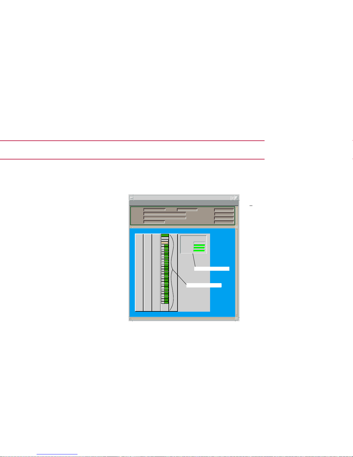
Figure 4: Chassis Device View
*File View Help
6C105 of type 6C105 of Landscape x: Primary
Model Name
Contact
Description
Location
Net Addr
Sys Up Time
Manufacturer
DeviceTyp e
Serial Number
Chassis Information
Power
Redundancy:
PS #1 Status:
PS #2 Status:
ChassisFans:
Chassis Module Icon
6E132-25
ModelName
Redundant
Normal
Normal
Normal
e1
4
FWD
e2
FWD
e3
FWD
e4
FWD
e5
FWD
e6
FWD
e7
FWD
e8
FWD
e9
FWD
e10FWD
e11FWD
e12FWD
e13FWD
e14FWD
e15FWD
e16FWD
e17FWD
e18FWD
e19FWD
e20FWD
e21FWD
e22FWD
e23FWD
e24FWD
Bridging
ChassisInformation
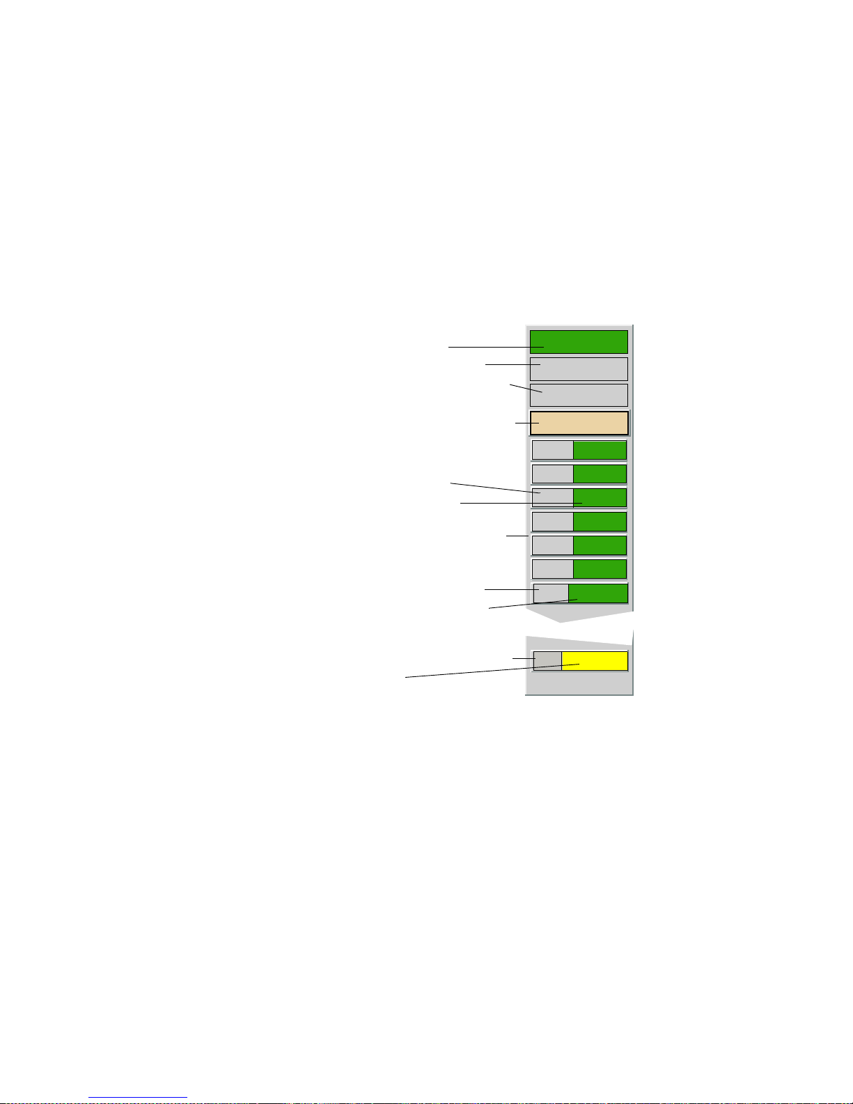
Figure 5: Chassis Module Icon
4
6E132-25
Model Name
e1
FWD
e2
FWD
e3
FWD
e4
FWD
e5
FWD
e6
FWD
Bridging
Model Type/Model Information View
Model Name/Device Configuration View
Slot Number/Application View
Module Identification Labels
Application Label/Performance View
Interface Type Label
Interface Status Label
(Accesses Bridging Icon Subviews)
Interface Labels
E2
UNLOCK
NLK
12
Repeater Labels
Repeater Port Labels
Repeater Index/Configuration View
Repeater Status/Performance View
Repeater Port Number/Port Notes View
Repeater Port Status
Chassis Module Icon Subviews
 Loading...