

Cabletron Systems 1088, SM-CSI1076, SmartSwitch 6000 SM-CSI1076, SmartSwitch 6000 SM-CSI1082, SmartSwitch 6000 SM-CSI1088 User Manual
Page 1
SmartSwitch 6000
Page 2

Restricted Rights Notice
(Applicable to licenses to the United States Government only.)
1. Use, duplication, or disclosure by the Government is subject to restrictions as
set forth in subparagraph (c) (1) (ii) of the Rights in Technical Data and
Computer Software clause at DFARS 252.227-7013.
Cabletron Systems, Inc., 35 Industrial Way, Rochester, New Hampshire 03866.
2. (a) This computer software is submitted with restricted rights.It may not be
used, reproduced, or disclosed by the Government except as provided in
paragraph (b) ofthisNotice or as otherwise expressly statedinthe contract.
(b) This computer software may be:
(1) Used or copied for use in or with t he computer or computers for which
it was acquired, including use at any Government installation to which
such computer or com puters may be transferred;
(2) Used or copied for use in a backup computer if anycomputer forwhich
it was acquired is inoperative;
(3) Reproduced for safekeeping (archives) or backup purposes;
(4) Modified, adapted, orcombined with othercomputer software,provided
that the modified, combined, or adapted portions of the derivative
software incorporating restricted computer software are made subject
to the same restricted rights;
(5) Disclosed to and reproduced for use by support service contractors in
accordance with subparagraphs (b ) (1) through (4) of this clause,
provided the Government mak e s such disclosure or reproduction
subject to these restricted right s; and
(6) Used or copied for use in or transferred to a replacement computer.
(c) Notwithstanding the foregoing, if this computer software is published
copyrighted computer software, it i s licensed to the Government, without
disclosure prohibitions,withthe minimum rights setforthin paragraph (b) of
this clause.
(d) Any other right s or limitations regarding the use, duplication, or disclosure
of this computer software are to be expressly stated in, or incorporated in,
the contract.
(e) This Notice shallbemarkedonanyreproduction of this computer software, in
whole or in part.
Page 3

Contents
Error Source (Selection).....................................15
Fast Ethernet Operation (Check) .......................15
Fast Ethernet Operational Mode (Check)...........15
FDDI Operation (Check).....................................16
Firmware (Upgrade)...........................................16
Model a SmartSwitch 6000 ................................16
Performance Statistics (View) ............................16
Port Operation (Monitor).....................................16
Port Operational Mode (Set) ..............................16
Ports (Configure)................................................16
Power Supply Status (Check) ............................16
Remote Hardware Received Tech (Check)........16
Repeater Frame and Error Stats (View).............16
Repeater Frame Size and Protocols (View).......16
Repeater Performance (Check) .........................16
Repeater Port Status (Check)............................16
Repeater Port Speed (Set) .................................17
Repeater Port Condition Display (Change)........17
Topology (Check)...............................................17
Traps (Set Up)....................................................17
Virtual Channel Operation (Check) ....................17
PERFORMANCE VIEWS 18
Device Performance View.............................................19
Bridging Performance View ..........................................19
Interface Performance View..........................................19
Page 4

Supported Applications............................................. 40
Fast Ethernet Application View .................................... 40
Fast Ethernet Port Table........................................... 40
ATM Client Application................................................. 41
ATM Client Application VCL Table............................ 42
Virtual Channel Link View.........................................44
CsRipEnetRpt Repeater Application ......................... 46
Download Application................................................... 46
CONFIGURATION VIEWS 47
Device Configuration View ........................................... 47
Interface Configuration Table.................................... 48
Port Configuration - CSIIfPort View.............................. 49
FddiMAC Device Configuration View ........................... 49
Station Configuration ................................................ 49
SMT Information ....................................................... 52
ATM Client Configuration View .................................... 52
Fast Ethernet Configuration View................................. 54
Operational Mode ..................................................... 54
Advertised Ability ...................................................... 55
Received Technology............................................... 55
Repeater Configuration View ....................................... 56
Repeater Management............................................. 56
Trap Configuration.................................................... 57
Alarm Configuration.................................................. 57
Error Source.............................................................. 58
Ethernet Based Configuration ...................................... 58
MODEL INFORMATION VIEW 60
Page 5

Page 6

Introduction
and navigation techniques, refer to the
documentation listed under Required Reading.
Required Reading
To use this documentation effectively, you must
be familiar with the information covered by the
other SPECTRUM online documentation topics
list below:
• Getting Started with SPECTRUM for
Operators
• Getting Started with SPECTRUM for
Administrators
• How to Manage Your Network with
SPECTRUM
• SPECTRUM Views
• SPECTRUM Menus
• SPECTRUM Icons
Page 7

Networking Characteristics
The SmartSwitch 6000 is designed with a fully
distributed switching architecture within each
module, which allows the modules to be managed
as a single entity, with a single module acting as a
proxy agent for the chassis, see odesManagement
Modes (page 9).
The SmartSwitch 6000 provides port mirroring,
port trunking, broadcast control, Quality of
Service (QoS), VLAN, and topology protocol, all in
either traditional 802.1d mode or Cabletron’s
SecureFast mode. Optional RMON support is also
available.
The SmartSwitch 6000 can provide the following
port connectivities:
• Switched Ethernet
• Switched Fast Ethernet
• MicroLAN Ethernet or Fast Ethernet
• Gigabit Ethernet uplinks
• OC-3, DS-3/E-3, and OC-12 switched ATM
Page 8

Standalone Mode
In this mode, each installed module provides its
own management functions. You configure all of
the modules in the chassis to Standalone mode
and assign separate IP addresses for each
module. SPECTRUM management is through the
representative Device icons created for each
module during discovery and modeling.
Mixed Mode
This mode provides a method of operationally
isolating a module (or modules) for security
purposes. You set an IP address for the chassis
and configure all non-secure modules in
Distributed mode. The secure module gets its own
IP address and is configured in Standalone mode.
SPECTRUM management is through the
representative Device icons created.
Page 9
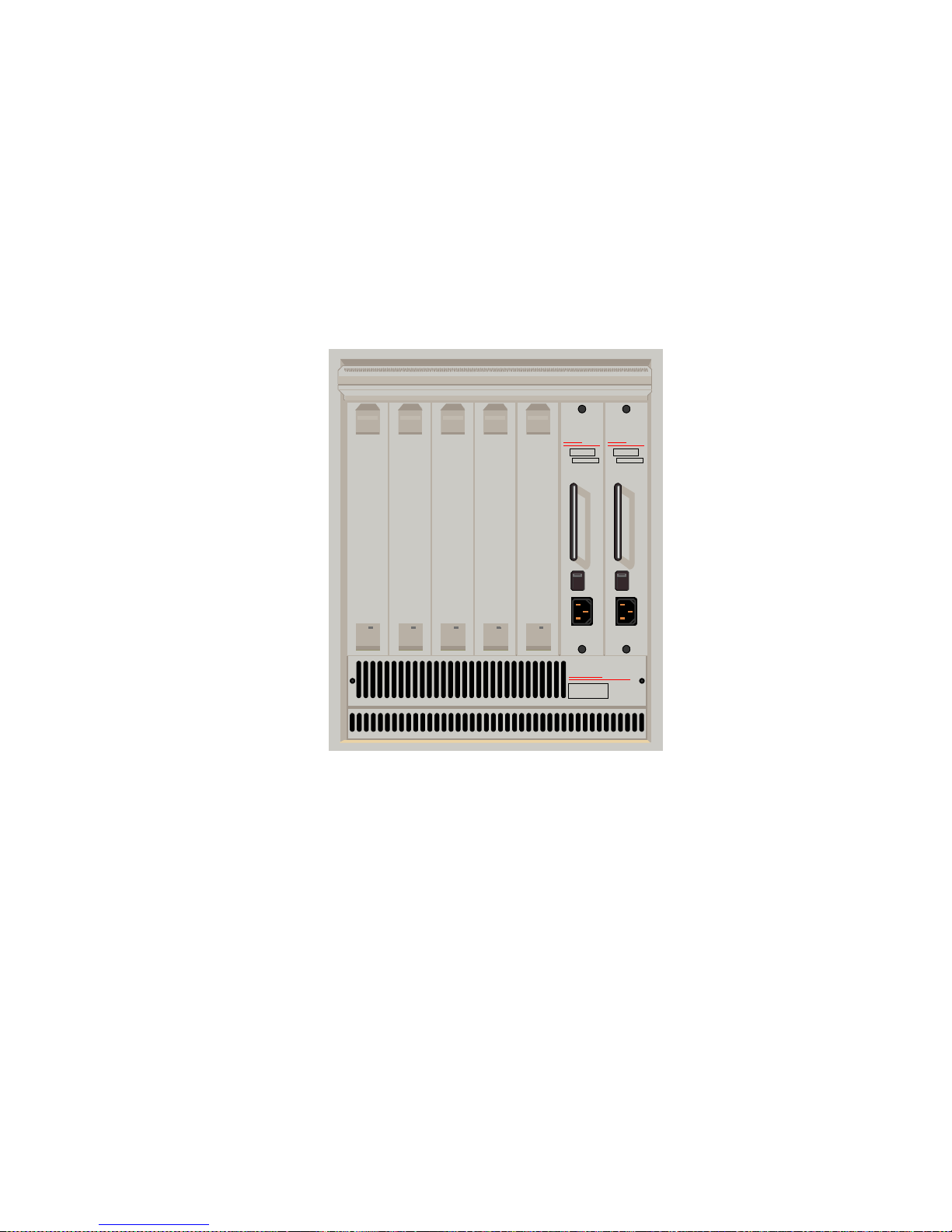
Figure 1: SmartSwitch 6000 Chassis
CaBLeTROn
SYSTeMS
6C105
Smart
SWITCH
6000
Smart
SWITCH
6000
Smart
SWITCH
6000
Smart
SWITCH
6000
Smart
SWITCH
6000
100 • 125 VAC
200 • 250 VAC
50 • 60 Hz
CaBLeTROn
SYSTeMS
PDK0 0 REDUNDANCY
6C205-1
B0096520019
SN
100 • 125 VAC
200 • 250 VAC
50 • 60 Hz
CaBLeTROn
SYSTeMS
PDK0 0 REDUNDANCY
6C205-1
B0096520019
SN
Page 10
6E Ethernet Modules
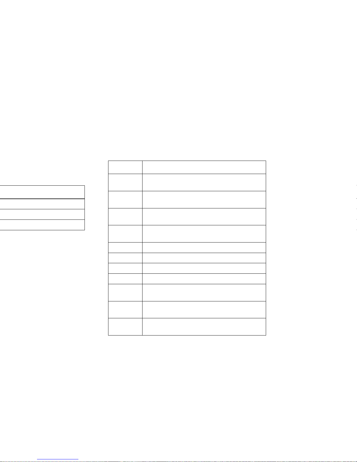
These modules provide the front panel ports and
interface uplink connectivities listed in Table 2.
Table 2: 6E Series Connectivities
Module Connectivity
6E122-26 24 10BaseT ports via RJ45 s pl us two F EPIM
slots
6E132-25 24 10BaseT ports via RJ45s plus one HSIM
slot
6E123-26 48 10BaseT po rts via two telc os plus two
FEPIM slots
6E133-25 24 10BaseT po rts via two telc os plus one
HSIM slot
6E128-26 24 ports via MMF STs plus two FEPIM slots
6E129-26 24 ports via SMF STs plus two FEPIM slots
6E138-25 24 ports via MMF STs plus one HSIM slot
6E139-25 24 ports via SMF STs plus one HSIM slot
6E123-50 48 MicroLan 10BaseT ports via RJ21 telcos
plus 2 FEPIM slots
6E133-49 48 MicroLan 10BaseT ports via RJ21 telcos
plus one HSIM slot
6E233-49 48 Ethernet ports via RJ21 telcos plus one
HSIM slot
Page 11
6M146-04 Carrier Module
This is a SmartSwitch carrier uplink module. It
provides two HSIM slots and two FEPIM slots.
The SPECTRUM Model
SPECTRUM lets you model and manage
individual modules or groups of modules on a
network installed in, or connected to, the chassis.
The models provide access to the information
needed to manage the modules, including
software emulation of the actual module
6H133-37 Three RJ21 telcos (12 ports each in any
combination of auto-negotiating 10Ba seT
Ethernet or 100BaseT Fast Ethernet) plus
one HSIM slot
6H203-24 24 port 10/100 switching module via two
RJ21 ports
6H253-13 12 port 10/100 switching module via one
RJ21 connector
6H258-17 16 MMF ports via MT-RJ connectors and
one VHSIM slot
6H262-18 6 fixed RJ45 ports and 2 FEPIM slots
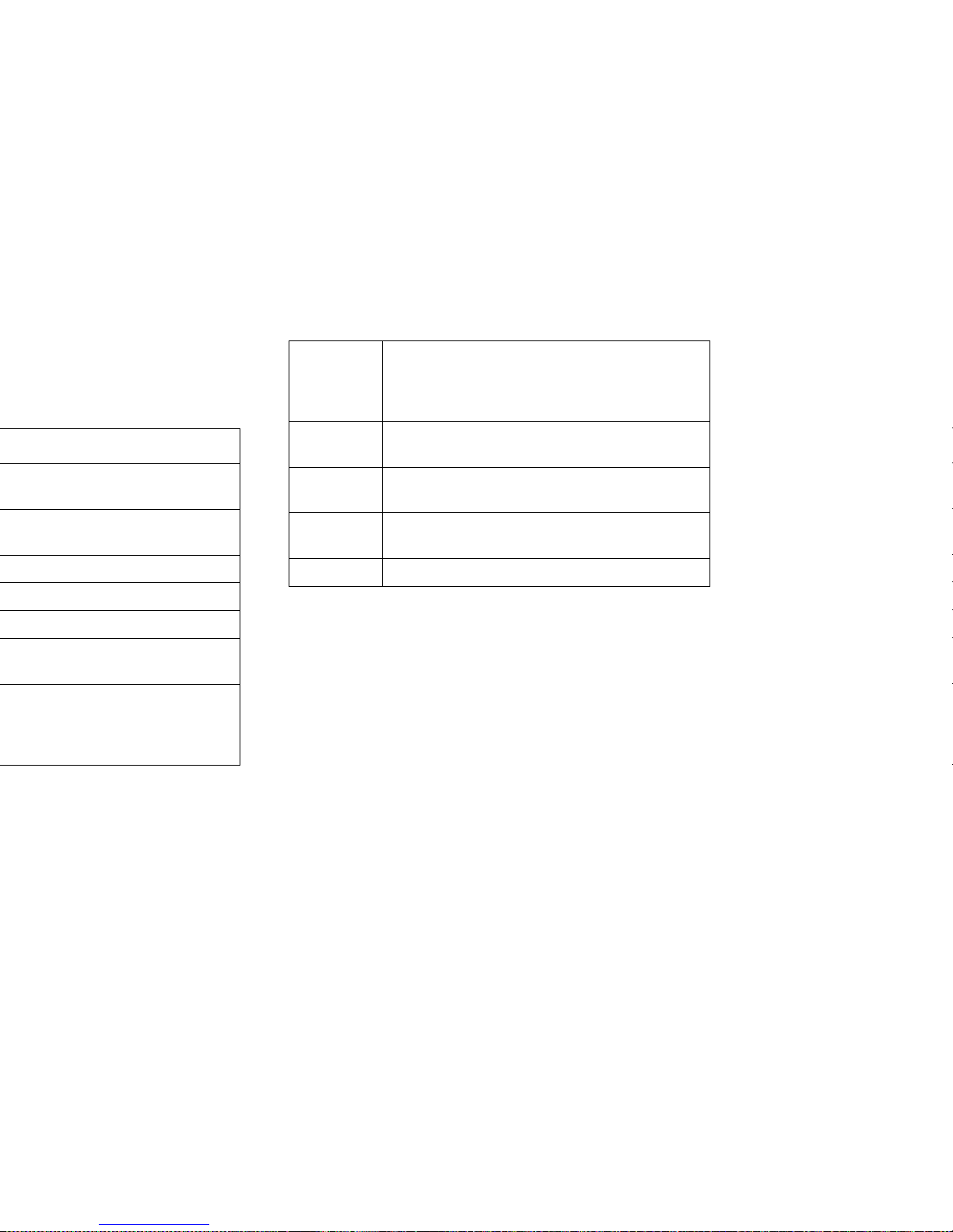
Table 3: 6H Series Connectivities
Page 12
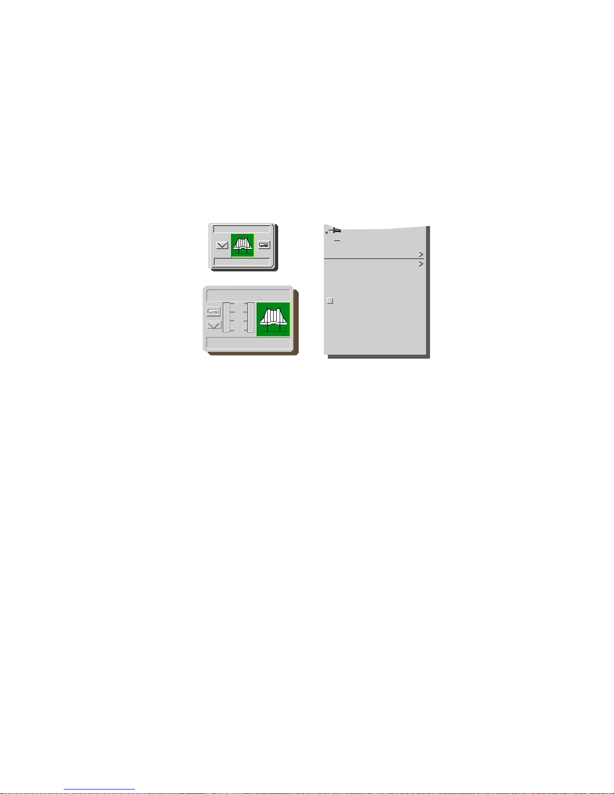
Figure 2: Device Icons
Close Ctrl +c
Navigate
Zoom
Device
DevTop
Application
Acknowledge
Flash Green Enabled
Configuration
Model Information
Primary Application
NetWideApp
10
1
.1
.01
IP Address
6H203_24
IP Address
6H203_24
Page 13

• ATM Client Configuration View (page 52)
(available with optional HSIM or FEPIM)
• Fast Ethernet Configuration View (page 54)
• Repeater Configuration View (page 56)
• Ethernet Based Configuration (page
58)(available for GPIM models)
• Model Information View (page 60)
Page 14

Tasks
Chassis Information (View)
• Chassis Device View (page 21)
Concentrator Status (Check)
• FddiMAC Device Configuration View (page 49)
Error Source (Selection)
• Error Source (page 58)
Fast Ethernet Operation (Check)
• Fast Ethernet Configuration View (page 54)
• Fast Ethernet Application View (page 40)
• Operational Mode (page 54)
• Advertised Ability (page 55)
• Received Technology (page 55)
• Ethernet Based Configuration (page 58)
Fast Ethernet Operational Mode (Check)
• Fast Ethernet Configuration View (page 54)
Page 15

Port Operational Mode (Set)
• Interface Labels (page 25)
Ports (Configure)
• Fast Ethernet Configuration View (page 54)
• Ethernet Based Configuration (page 58)
Power Supply Status (Check)
• Chassis Information (page 29)
Remote Hardware Received Tech (Check)
• Received Technology (page 55)
Repeater Frame and Error Stats (View)
• Repeater Frame & Error Breakdown View
(page 27)
Repeater Frame Size and Protocols (View)
• Repeater Frame Size & Protocols View (page
27)
Repeater Performance (Check)
• Repeater Label Icon Subviews(Table 8)
Repeater Port Status (Check)
• Repeater Configuration View (page 56)
• CsRipEnetRpt Repeater Application (page 46)
Page 16

Page 17
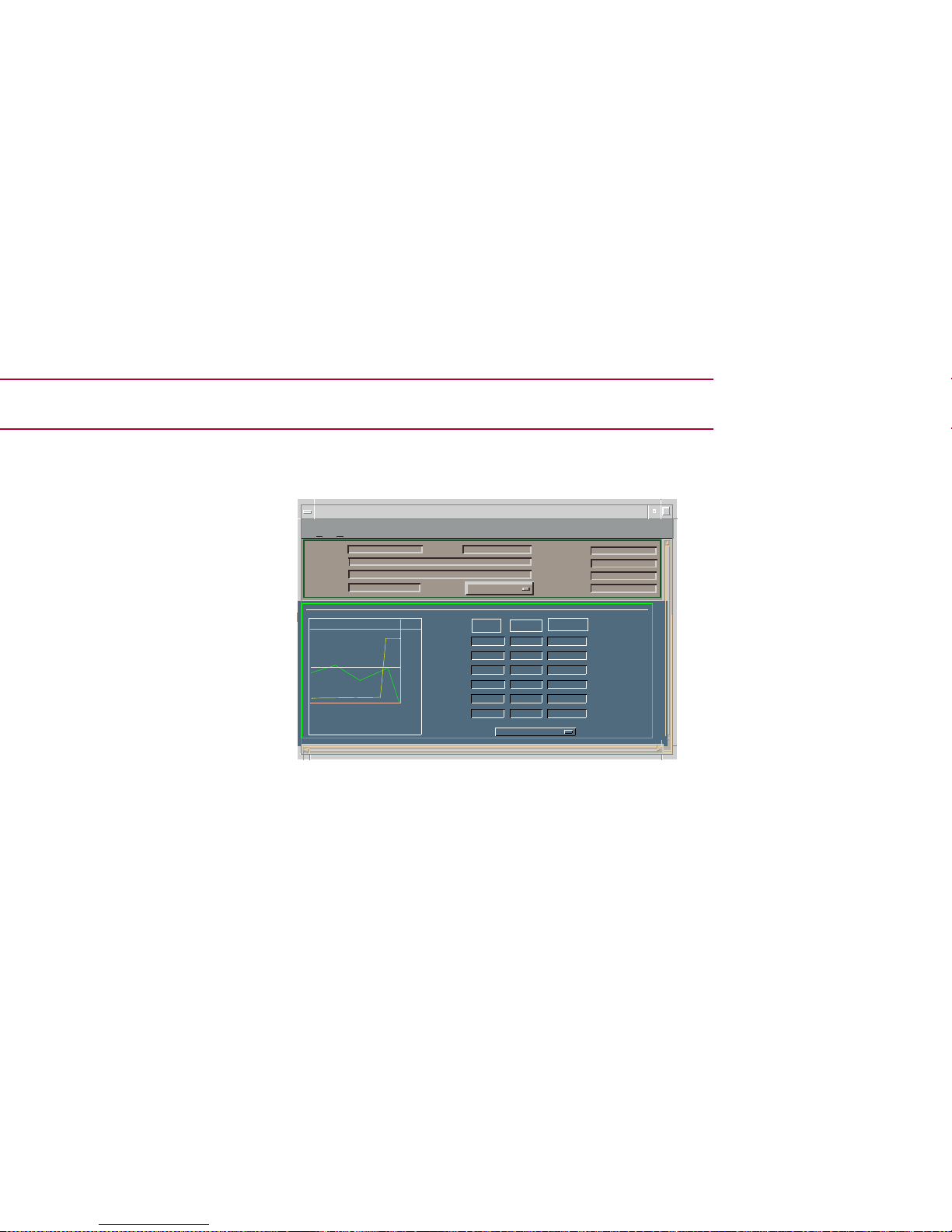
Performance Views
Figure 3: Device Performance View
*
File View
H
elp
IP address of type 6E132_25 of
Landscape VNMHost: Primary
Model Name
Contact
Description
Location
Net Addr
Prime-App
Sys Up Time
Manufacturer
DeviceType
Serial Number
Log
100.0
10.00
1.00
0.10
0.01
0
0
0:40:0
0:30:0
0:20:0
Value
Average
Peak Value
%Receive Rtr
%FIltered
%Forwarded
%TransRate
Graph Properties
Scroll to Date-Time
Page 18

InterfacePerformanceView
Access: From the Icon Subv iews menu of the I nterfa ce
icon, select Performance.
This view provides the following information on
current and historical packet transmission
statistics, and error load statistics for the selected
interface:
• % Transmitted
• % Discarded
• % Error
• % Host Bound
• In Packet Rate
• Out Packet Rate
• Total Packet Rate
• In Load
• Out Load
• Total Load
Page 19

Page 20
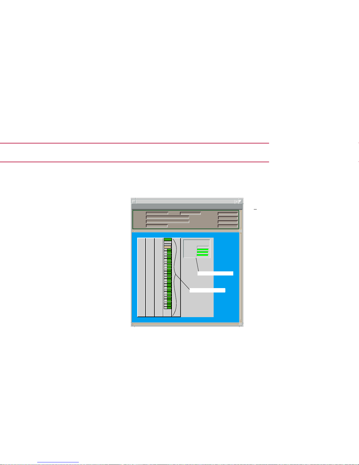
Device Views
Figure 4: Chassis Device View
*File View Help
6C105 of type 6C105 of Landscape x: Primary
Model Name
Contact
Description
Location
Net Addr
Sys Up Time
Manufacturer
DeviceTyp e
Serial Number
Chassis Information
Power
Redundancy:
PS #1 Status:
PS #2 Status:
ChassisFans:
Chassis Module Icon
6E132-25
ModelName
Redundant
Normal
Normal
Normal
e1
4
FWD
e2
FWD
e3
FWD
e4
FWD
e5
FWD
e6
FWD
e7
FWD
e8
FWD
e9
FWD
e10FWD
e11FWD
e12FWD
e13FWD
e14FWD
e15FWD
e16FWD
e17FWD
e18FWD
e19FWD
e20FWD
e21FWD
e22FWD
e23FWD
e24FWD
Bridging
ChassisInformation
Page 21
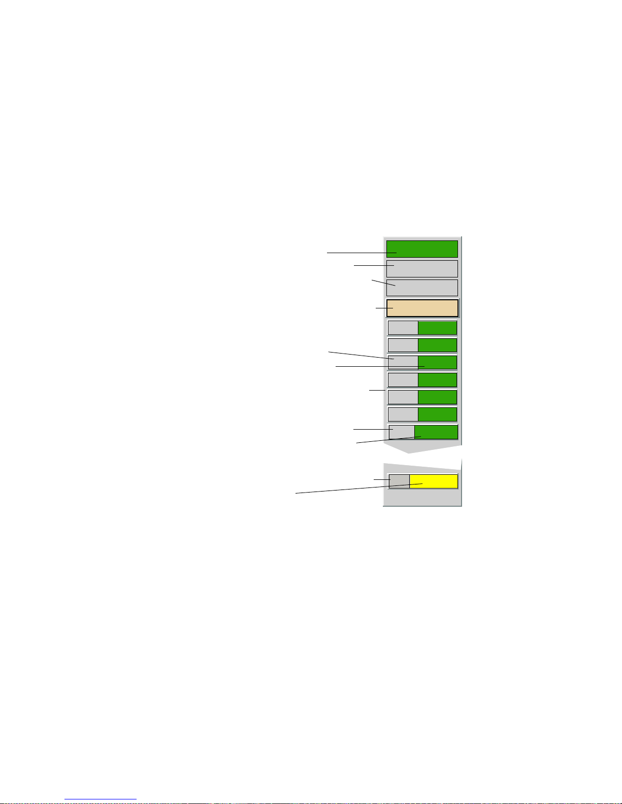
Figure 5: Chassis Module Icon
4
6E132-25
Model Name
e1
FWD
e2
FWD
e3
FWD
e4
FWD
e5
FWD
e6
FWD
Bridging
Model Type/Model Information View
Model Name/Device Configuration View
Slot Number/Application View
Module Identification Labels
Application Label/Performance View
Interface Type Label
Interface Status Label
(Accesses Bridging Icon Subviews)
Interface Labels
E2
UNLOCK
NLK
12
Repeater Labels
Repeater Port Labels
Repeater Index/Configuration View
Repeater Status/Performance View
Repeater Port Number/Port Notes View
Repeater Port Status
Chassis Module Icon Subviews
Page 22

Table 4: Module Icon Subviews Menu Options
Menu
Selection
Opens the...
DevTop Device Topology view described in
SPECTRUM View s .
Application Applications View (page 38).
Configuration Device Configuration View (page 47).
Model
Information
Model Information view described in
SPECTRUM View s .
Interface Interface Device View (page 30).
Application
Display
Application selection dialog box,
which allows you to select the
application to be displayed in the
Application label. Example: Bridging.
Basic Alarms Basic Alarms view described in the
SPECTRUM Portable Mana g eme nt
Application for the SmartSwitch
6000 User’s Guide.
Page 23

Table 5: Bridging Application Icon Subviews
Option Opens the...
Bridge
Performance
Bridge Performance view described
in SPECTRUM Views.
Bridge Detail Bridge Detail view described in
Bridging Applications.
Bridge Model
Information
Model Information view described in
SPECTRUM Views.
Smart
Trunking
SmartTrunking Configuration and
Status screen described in SPMA
views.
Spanning Tree
Information
Spanning Tree Information view
described i n Bridging Applications.
Static Database
Table
Static Database Table view described
in Bridging Applications.
Transparent
Bridge
Information
Transparent Bridge Information view
with Forwarding Database and Port
tables described in Bridging
Applications.
Page 24

Table 6: Bridging Application Interface
Status
Table 7: Physical Application Interface Status
Color Status Description
Green FWD Bridge port is forwarding.
Blue DIS Port is disabled.
Magenta LST Bridge is in the listening mode.
Magenta LRN Bridge is in the learning mode.
Blue SBY Bridge port is in the standby
mode.
Orange BLK Bridge port is in the blocking
mode.
Red BRK Bridge port is broken.
Blue UNK The status is unkn own.
Color Status Description
Green ON Port is operational.
Blue OFF Port is off.
Yellow TST Port is in the test mode.
Page 25

Repeater Status
Displays the repeater operational status and
provides double-click access to the Performance
View, which is described in SPECTRUM Views.
The Repeater labels also provide access to the
Icon Subviews menu listed in Table 8.
Table 8: Repeater Label Icon Subviews Menu
Menu
Selection
Opens the...
Repeater
Performance
Performance view described in
SPECTRUM View s .
Repeater Fr ame
& Error
Breakdown
Repeater Frame & Error Breakdown
View (page 27).
Repeater Fr ame
Size & Protocols
Repeater Fram e Size & Proto cols V iew
(page 27).
Repeater
Configuration
Repeater Configuration View (page
56).
Repeater Model
Information
Model Information view described in
SPECTRUM View s .
Repeater Port
Display Form
Repeater Po rt Disp lay F orm (page 27 ),
which lets you select the type of
status display ed.
Page 26

Clear
Restarts the counter. The values will continue to
accumulate until Clear is selected or another
representation mode is selected.
For more information on the individual error
types, refer to How to Manage Your Network
with SPECTRUM.
Repeater Frame Size & Protocols View
This view displays a statistical breakdown of
frame sizes and protocols for a selected repeater
port. The frame size and protocol breakdowns are
displayed in the form of pie charts and tables (as
described above for the Repeater Frame & Error
Breakdown view).
Repeater Port Display Form
This option on the Repeater label Icon Subviews
menu provides three choices: Admin, Link, and
Speed. These choices determine which
operational condition is displayed on the
associated Repeater Port labels. For example, if
Note:
Note:
Selecting Total, Delta, or Accum affects
the numerical as well as graphical
representation of every item contributing
to the total.
Page 27

Table 9: Repeater Port Label Icon Subviews
Repeater Port Number
Shows an index number identifying a particular
repeater port.
Repeater Port Status
Indicates the port activity status.
The Repeater Port Frame & Error Breakdown view
and Repeater Port Frame Size & Protocols view
provide pie charts and tables that are similar to
what is described for the Repeater Frame & Error
Breakdown View (page 27) and the Repeater
Frame Size & Protocols View (page 27).
Menu
Selection
Description
Port Notes Opens a note pad for your use.
Port Frame &
and Error
Breakdown
Opens the Repeater Port Frame &
Error Breakdown view.
Port Frame Size
& Protocols
Opens the Repeater Port Frame Size &
Protocols view.
Enable/Disable
Port
Opens a dialog box that lets you
enable or disable the port.
Set Port Speed Opens a dialog box that lets you set
the port speed to Auto, 10 Mbps, o r
100 Mbps.
Page 28
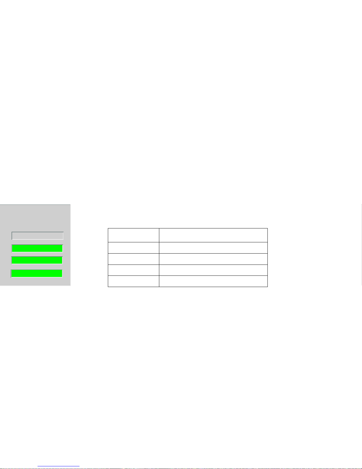
PS #1 Status
Displays the current status of power supply one.
PS #2 Status
Displays the current status of power supply two.
Chassis Fans
Displays the operation state of the chassis fans.
Table 10 lists the possible states and color
indication for the power supplies and chassis
fans.
Table 10: Chassis Information Status
Definitions
Redundant
Normal
Normal
Normal
Color Definition
Green Normal
Gray Not installed
Red Not operational
Blue Unknown
Page 29
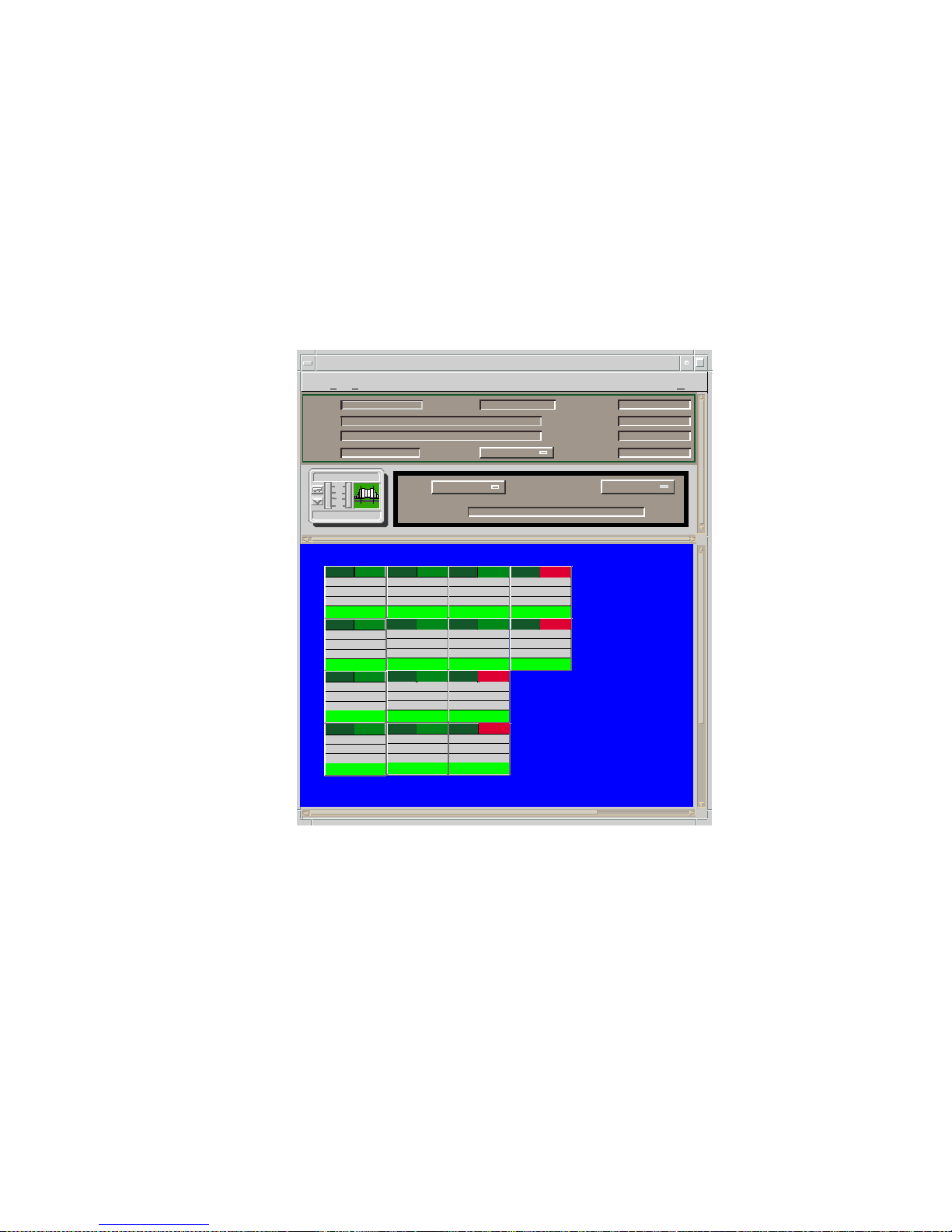
Figure 7: Interface Device View
* File View Help
IP Address on type6E122_26 of Landscape x: Pr imary
Filter
InterfaceDescription
Network Information
ADDRESS
Physical
Model Name
Contact
Description
Location
NetworkAddress
SystemUp Time
Manufacturer
DeviceType
SerialNumber
Primary-Application
Model Name
6E122_26
ETHERNET
0:01D:17:2F:3C
0
ETHERNET
0:01D:17:2F:3C
0
ETHERNET
0:01D:17:2F:3C
0
e1
ETHERNET
0:01D:17:2F:3C
0
ON e5 ON e9
ON
b5 OFF
ETHERNET
0:01D:17:2F:3C
0
ETHERNET
0:01D:17:2F:3C
0
ETHERNET
0:01D:17:2F:3C
0
e2
ETHERNET
0:01D:17:2F:3C
0
ON
e6 ON
e10
ON
b1
OFF
ETHERNET
0:01D:17:2F:3C
0
ETHERNET
0:01D:17:2F:3C
0
e4
ETHERNET
0:01D:17:2F:3C
0
ON
e8 ON
b4
OFF
ETHERNET
0:01D:17:2F:3C
0
ETHERNET
0:01D:17:2F:3C
0
e3
EHERNET
0:01D:17:2F:3C
0
ON
e7 ON
b2 OFF
10
1
.1
.01
Page 30
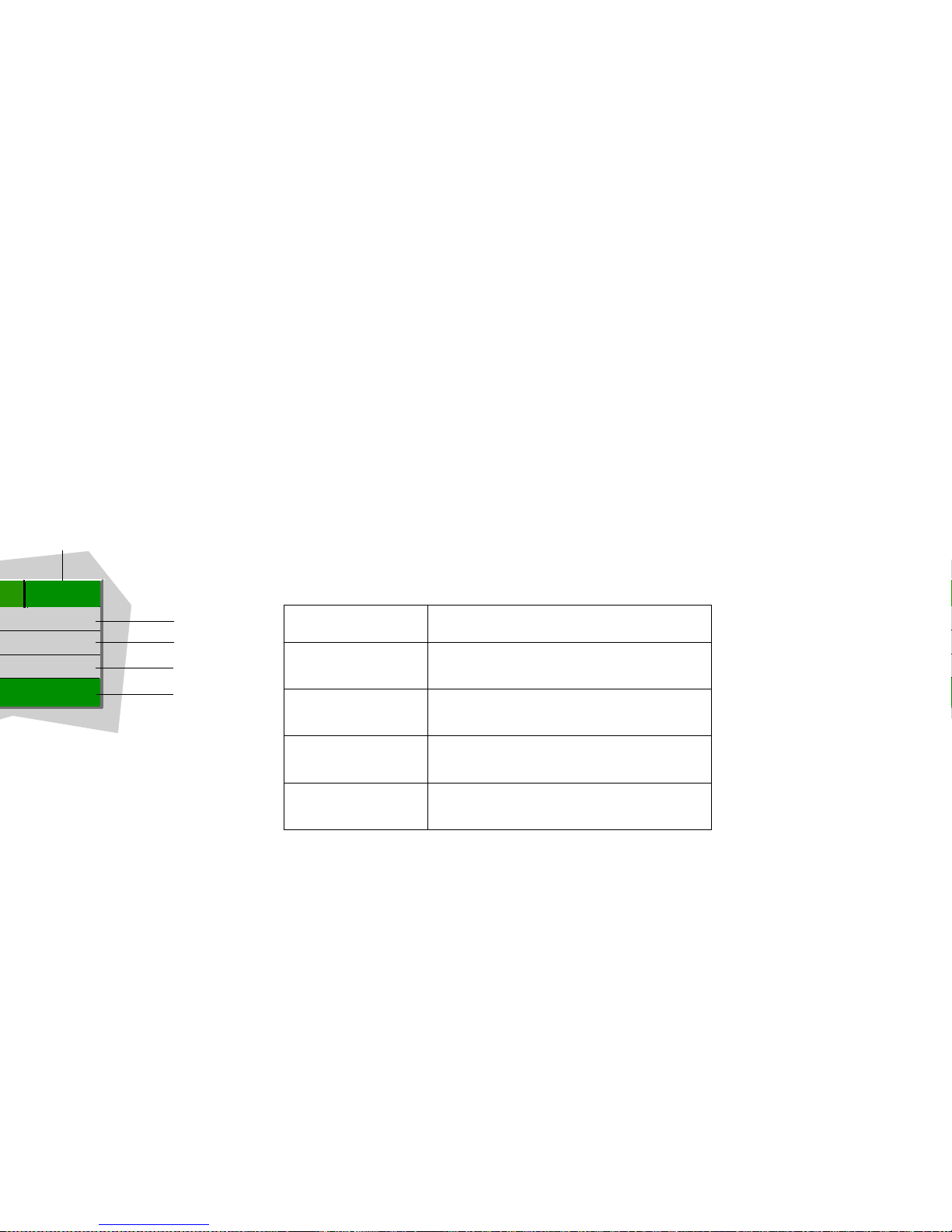
Interface Number Label
This label identifies this interface (”e” indicates an
Ethernet interface, “b” indicates a backplane
interface, and the numeral represents the
interface number on this module).
Interface Type Label
This label displays the type of network interface
module (e.g., Ethernet, FDDI, etc.).
Interface Icon Subviews
Table 11 describes each of the Icon Subviews
menu selections available for the Interface icon.
Administrative Status Label
This label displays the state of this port (On, Off,
Testing). Table 12 and Table 13 list the possible
states relative to the application selected. The
(c)
(
d)
(
e)
(
f)
0
ON
Table 11: Interface Icon Subviews
Menu Selection Opens the...
Configuration Port Configuration - CSIIfPort View
(page 49).
Secondary
Address Panel
Panel that provides the second ar y
address and mask for the interface.
Protocols
(with HSIM only)
ATM Client Application (page 41).
Model
Information
Model Information view des cribed in
SPECTRUM Views.
Page 31
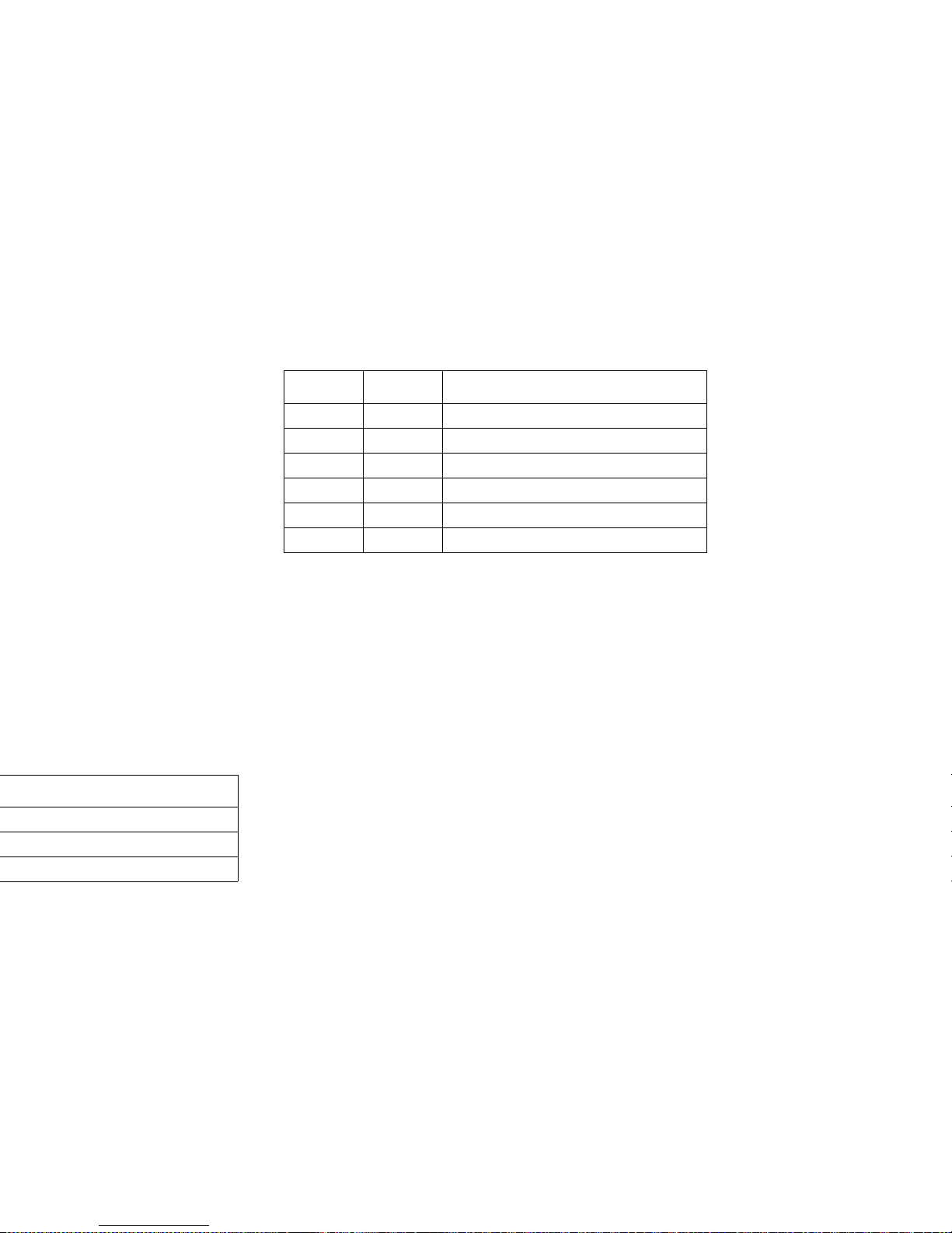
Table 13: Bridging Application
Administrative Status
Gauge Label
This label displays the performance statistic that
you set in the Gauge Control Panel, which is
accessible from the Interface Options panel.
Double-click this label to access the Performance
view. For me information seethe information in
the SPECTRUM Views documentation.
Backplane Device View
Access: From the Chassis Devi ce vi ew , se lect View >
Page > Back plane.
A sample Backplane Device view is shown in
Figure 9. The view contains Backplane Module
icons that represent the backplane connections
Color Status Description
Green FWD Bridge port is forwarding
Blue DIS Port is disabled
Magenta LST Bridge is in listening mode
Magenta LRN Bridge is in learning mode
Orange BLK Bridge port is in blocking mode
Red BRK Bridge port is broken
Page 32
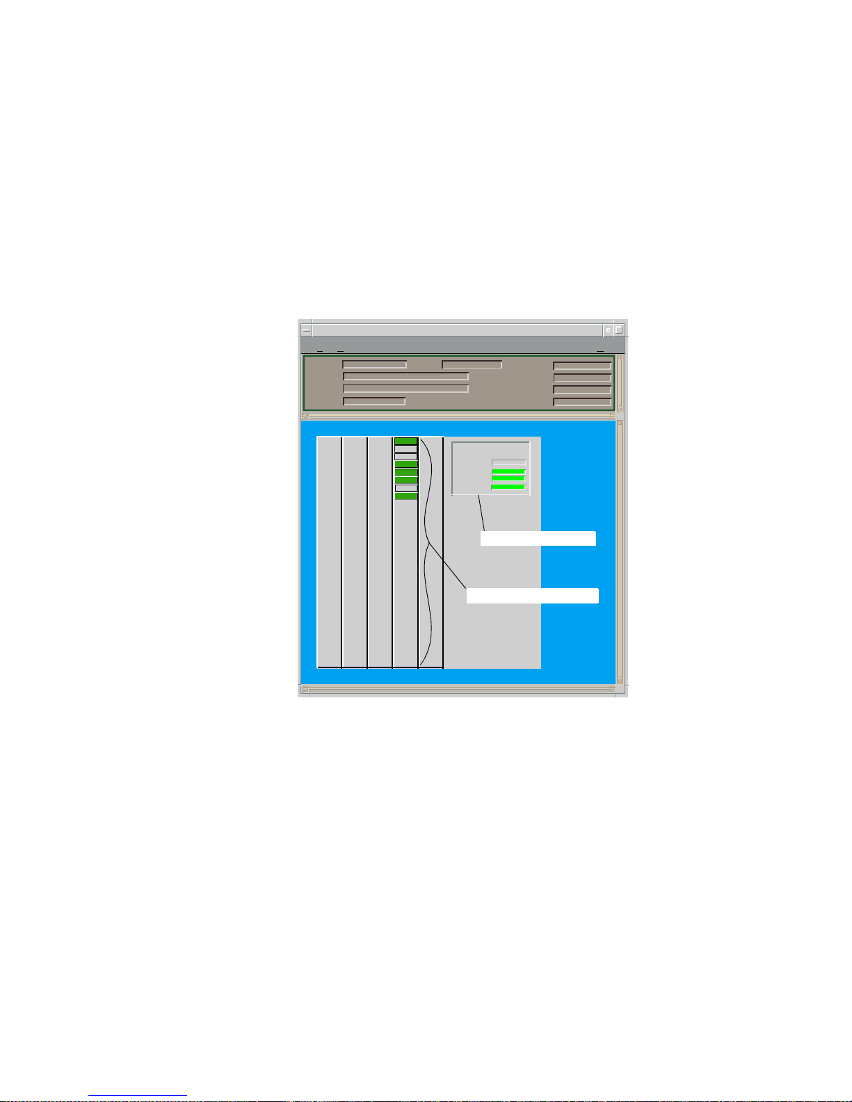
Figure 9: Backplane Device View
* File View Help
6C105
of type 6C105 of Landscape x: Primary
Model Name
Contact
Description
Location
Net Addr
Sys Up Time
Manufacturer
DeviceType
Serial Number
Chassis Information
Power
Redundancy
:
PS #1 Status:
PS #2 Status:
Chassis Fans:
Backplane Module Icon
Chassis Information
6E132-25
Model Name
b1
Redundant
Normal
Normal
Normal
b2
b3
b4
b5
4
Page 33
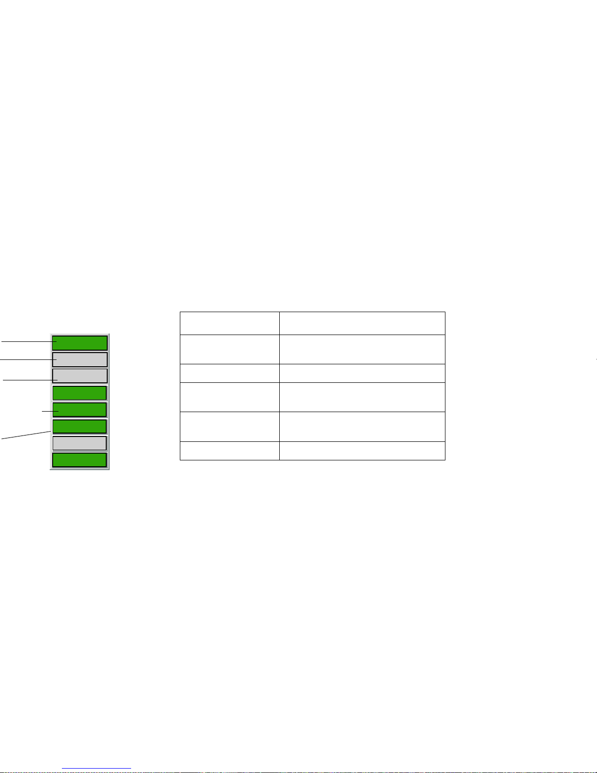
Backplane Module Icon
Subviews
Table 14 describes the device-specific Backplane
Module Icon Subviews menu selections for the
module.
Table 14: Backplane Module Icon Subviews
6E132-25
b1
4
Model Name
b2
b4
b5
b3
Option Open the...
DevTop Device Topology view described in
SPECTRUM View s.
Application Applications View (page 38).
Configuration Device Configuration View (page
47).
Model Information Model Information view described
in SPECTRUM Views.
Interface Interface Devic e View (page 30).
Page 34

has a gray Backplane Connection label (b4),
which corresponds with interface four of the
chassis backplane.
Table 15 describes the possible operational states
of the backplane connections.
Table 15: Backplane Connection Status
Descriptions
Chassis Information
The Chassis Information panel within the
Backplane Device view provides the same
information as a similar panel in the Chassis
Device view described under Chassis Information
(page 29).
Color Status Description
Green ON Operational
Yellow NLK Operational but not linked
Magenta Test Operational test
Blue Off Operationally and administratively
down
Red Off Operationally down but
administratively enabled
Gray UNK Unknown
Page 35
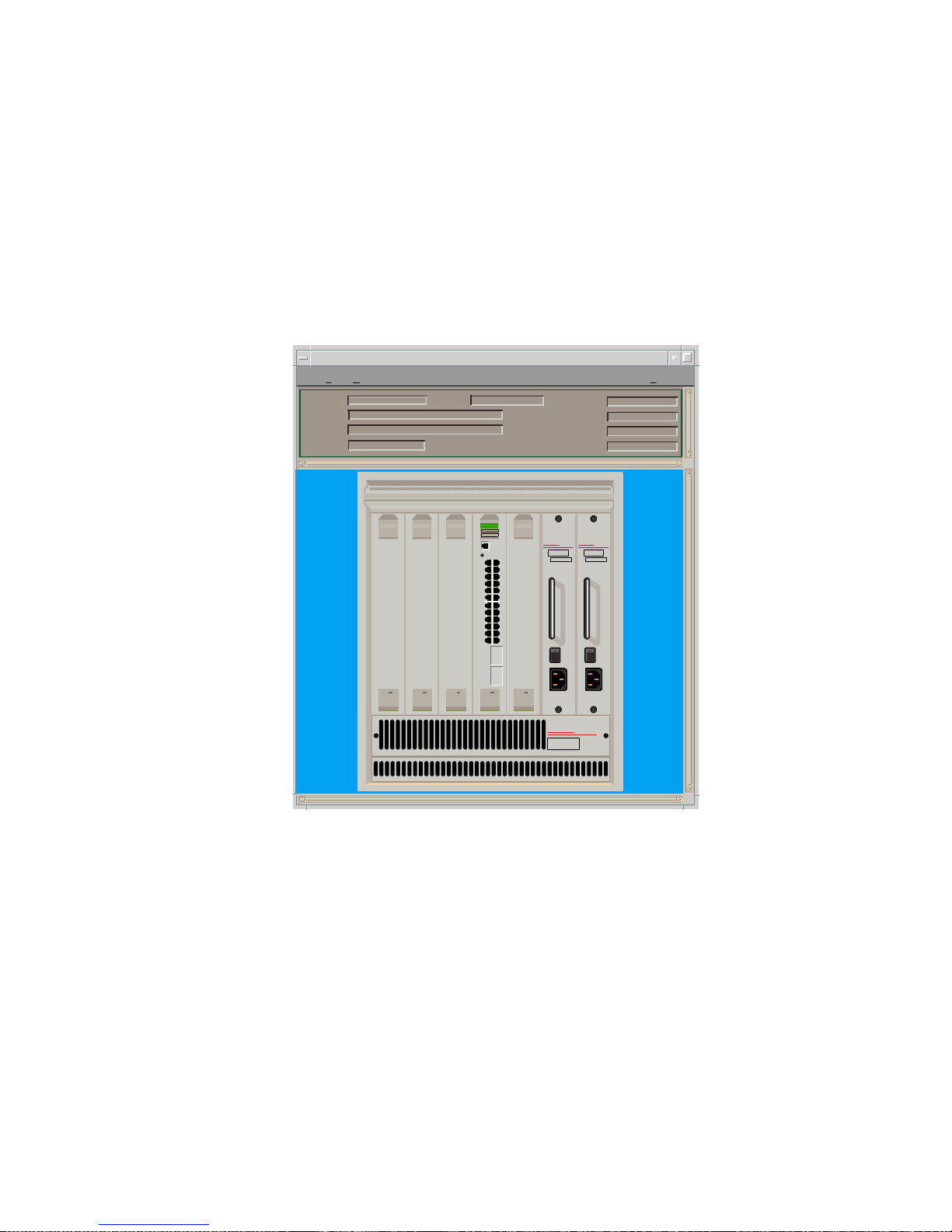
Figure 11: Physical Device View
* File View Help
6C105 of type 6C105 of Landscape x: Primary
Model Name
Contact
Description
Location
Net Addr
Sys Up Time
Manufacturer
DeviceType
Serial Number
CaBLeTROn
SYSTeMS
6C105
Smart
SWITCH
6000
Smart
SWITCH
6000
Smart
SWITCH
6000
Smart
SWITCH
6000
100 • 125 VAC
200 • 250 VAC
50 • 60 Hz
CaBLeTROn
SYSTeMS
PDK0 0 REDUNDANCY
6C205-1
B0096520019
SN
100 • 125 VAC
200 • 250 VAC
50 • 60 Hz
CaBLeTROn
SYSTeMS
PDK0 0 REDUNDANCY
6C205-1
B0096520019
SN
Smart
SWITCH
6000
1X
3X
5X
7X
9X
11X
13X
15X
17X
19X
21X
23X
6E132-25
ETHERNET
COM
CPU
Page 36
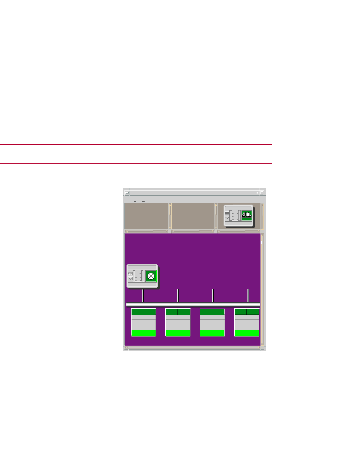
Device Topology View
Figure 12: Device Topology View
*
File View
H
elp
IP Address of type 6H203_24 of Landscape x: Primary
Model Type
Model Type
1
FWD
ETHERNET
0.0.2.1.0.5.1.A:BC
0
2
FWD
ETHERNET
0.0.2.1.0.5.1.A:BC
0
3
FWD
ETHERNET
0.0.2.1.0.5.1.A:BC
0
4
FWD
ETHERNET
0.0.2.1.0.5.1.A:BC
0
Model Type
Model Type
10
1
.1
.01
10
1
.1
.01
Page 37
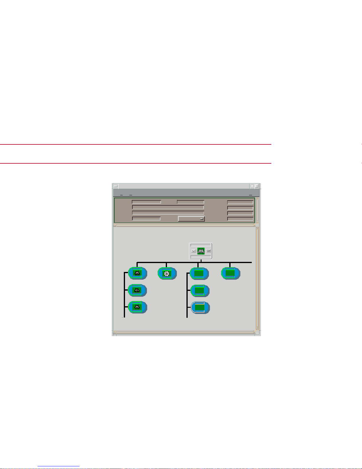
Applications View
Figure 13: Application View
*
File View
H
elp
IP Address of type 6E132_25 of Landscape VNM: Primary
Model
Contact
Description
Location
Net Addr
Prime-App
SysUp Time
Manufacturer
DeviceTy pe
Serial Number
Model Name
6E132_25
Page 38
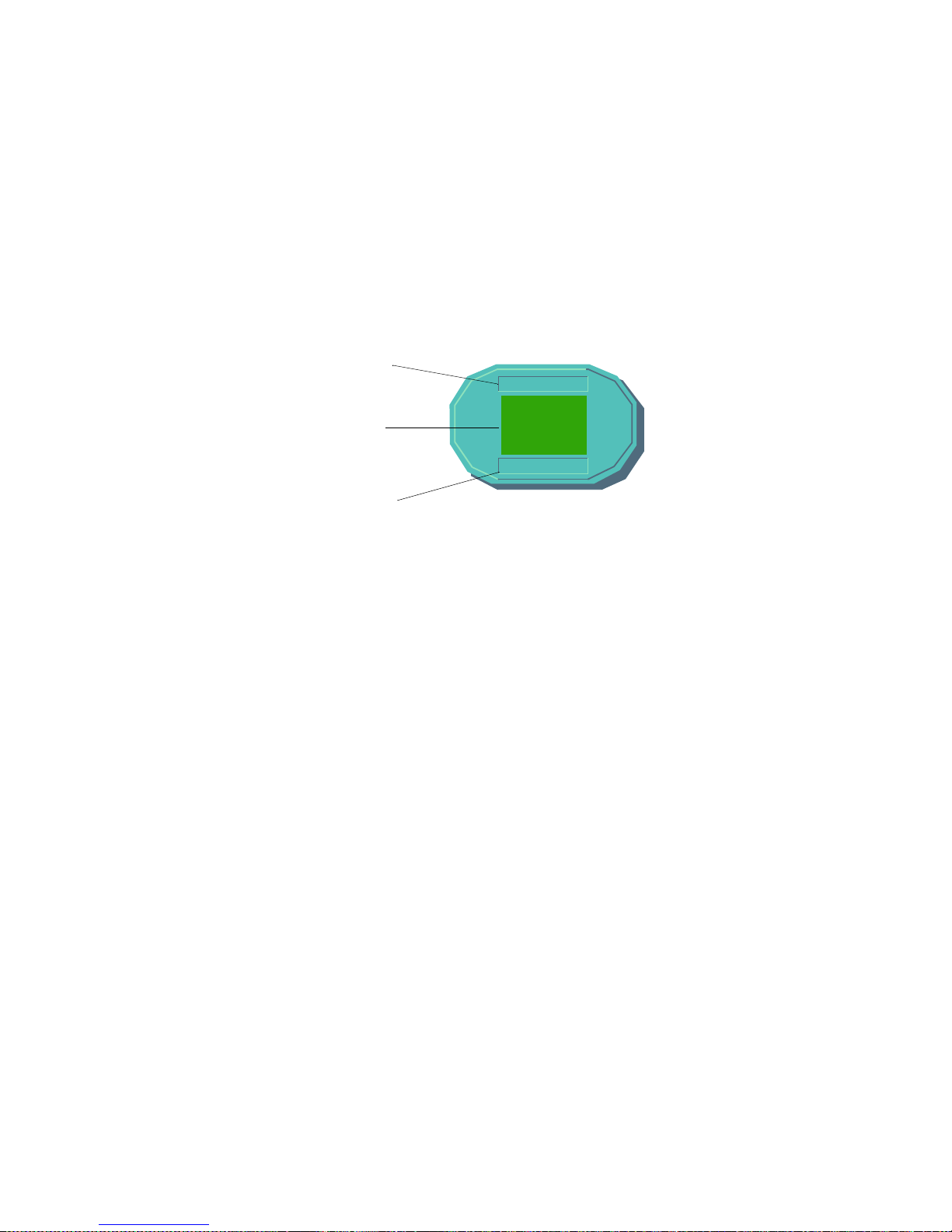
Figure 14: Application Icon
a Model Name Label/ Model Information View
b Condition Status Label
c Model Type Label / Application Specific View
IP2_App
modelname_IP
IP2_App
(a)
(b)
(c)
Page 39

Fast Ethernet Application View
Access: From the Icon Subviews menu for the
Application icon, select Fast Ethernet or Double-click
the Application icon.
This view provides access to the Model
Information view (described in SPECTRUM
Views) and the Fast Ethernet Port Table
described below.
Fast Ethernet Port Table
This section of the Fast Ethernet Application
views provides the information described below,
and also provides access to the Fast Ethernet
Configuration View (page 54) when you double-
click any entry in the table. The Fast Ethernet
Table 16: Common Applications
Application For more info, see...
Bridging
(CSIBridge)
Bridging Application
MIB-II
(SNMP2_Agent)
MIB II Applications
Standard RMON Standard RMON
Page 40
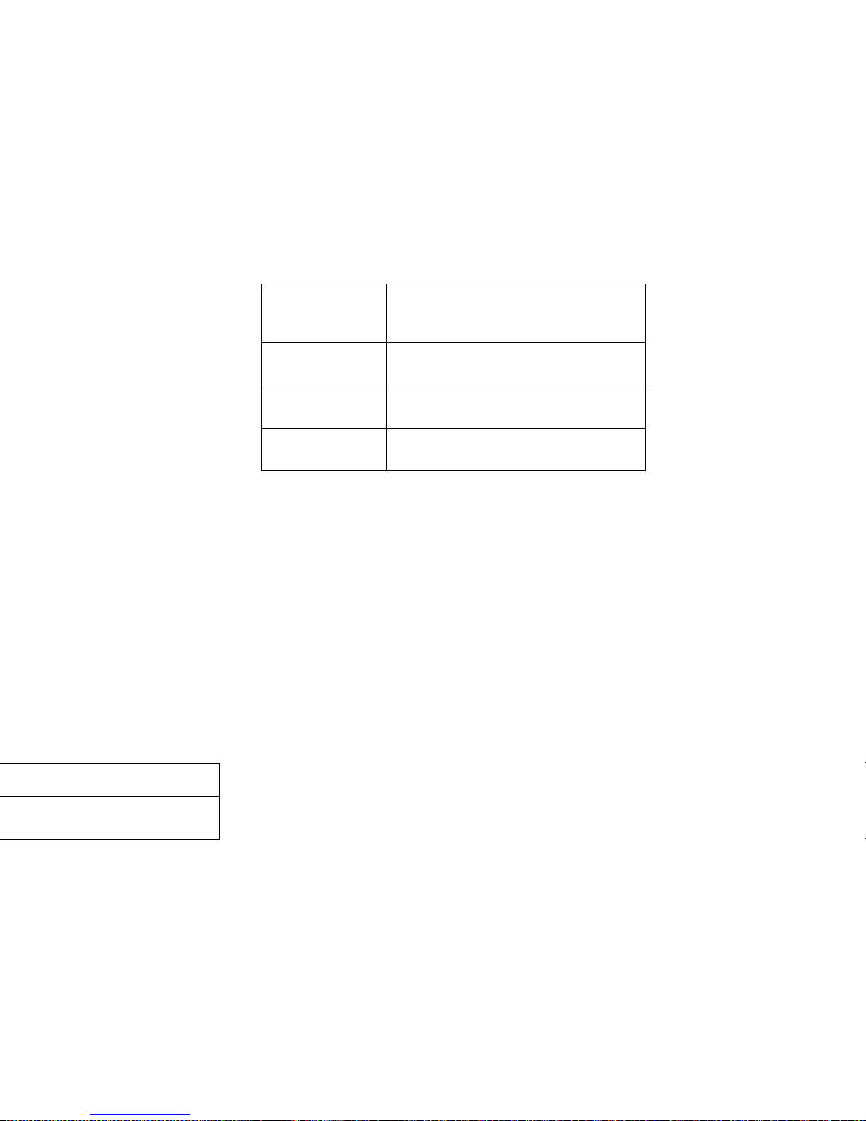
ATM Client Application
This application is used to monitor and control
ATM channels via the ATM Client Application VCL
Table described below. Table 18 lists the
application-specific subviews available for the
application.
Station List Opens the FDDI Station List view
described in Miscellaneous
Applications.
Acknowledge Allows you to acknowledge an alarm
condition.
Configuration Opens the Device Configuration View
(page 47).
Model
Information
Opens the Model Information view
described in SPECTRUM Views.
Page 41
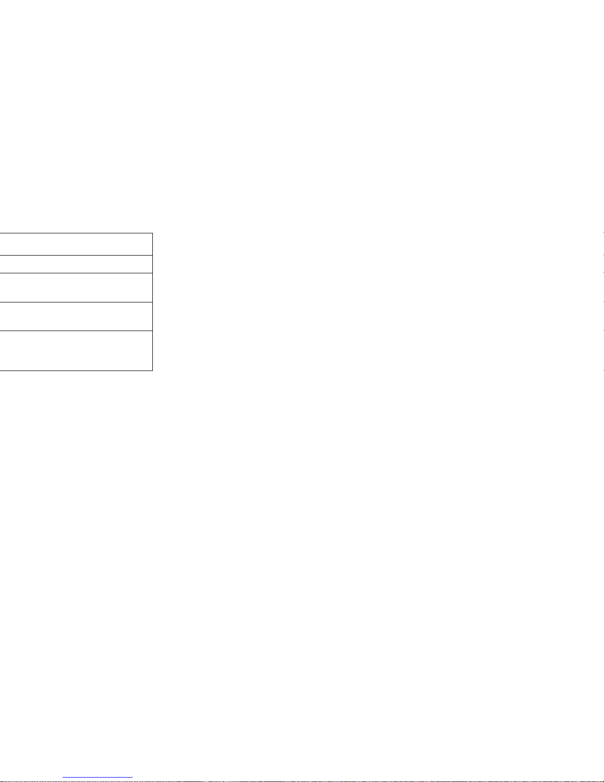
Last Change
The value of sysUpTime at the time this VCL
entered its current operational state. If the
current state was entered prior to the last reinitialization of the agent, then this field contains
a zero value.
RTD (Receive Traffic Description) Index
The value of this field identifies the row in the
ATM Traffic Descriptor Table that applies to the
receive direction of this VCL.
TTD (Transmit Traffic Description) Index
The value of this field identifies the row of the
ATM Traffic Descriptor Table that applies to the
transmit direction of this VCL.
AAL (ATM Adaptation Layer) Type
An instance of this field only exists when the local
VCL endpoint is also the VCC endpoint and AAL
is in use. The field indicates the type of AAL used
on this VCC, which includes AAL1, AAL3/4, and
AAL5. The “other” type is a user-defined AAL type.
The “unknown” type indicates that the AAL type
cannot be determined.
Transmit Size
An instance of this field only exists when the local
VCL endpoint is also the VCC endpoint and AAL5
is in use. The field indicates the maximum AAL5
Page 42

Row Status
This field is used to create, delete, or modify a row
in this table. To create a new VCL, this field is
initially set to “createAndWait” or “createAndGo.”
This field must not be set to “active” unless the
following columnar fields exist in this row:
• RTD Index
• XTD Index
• AAL Type (if the local VCL endpoint is also the
VCC endpoint)
• Transmit Size (for AAL5 connections only)
• Receive Size (for AAL5 connections only)
• Encaps Type (for AAL5 connections only)
To make a change to the rows in the table view,
do the following:
1 In the Communication Information panel,
change the Community Name field to
“private.”
2 From the Icon Subviews menu, select Table
View.
Note:
Note:
The Community Name field in the
Communication Information panel of the
Model Information view must be set to
“private” in order to change the fields in
the table views.
Page 43

VCI (Virtual Channel Identifier)
Displays the VCI value of the VCL. The maximum
VCI value cannot exceed the value allowable by
the Interface MaxVCI Bits.
Admin Status
Implemented only for a VCL that terminates a
VCC (i.e., one that is not cross-connected to other
VCLs). Its value (Up or Down) specifies the desired
administrative state of the VCL, i.e., whether
traffic flow is enabled and disabled for this VCL.
Oper Status
Indicates the current operational status of the
VCL. “Up” and “Down” indicate that the VCL is
operational or not operational, respectively.
Unknown indicates that the status of this VCL
cannot be determined.
Row Status
Used to create, delete or modify a row in this
table. To create a new VCL, this field is initially
set to “createAndWait” or “createAndGo”. This
field must not be set to “active” unless the
following columnar fields exist in this row:
• RTD Index
• XTD Index
• AAL Type (if the local VCL endpoint is also the
VCC endpoint)
• Transmit Size (for AAL5 connections only)
Page 44

are identified by entries in the Cross Connect
Table for which VCL CC Id has the same value.
The value of this field is initialized by the agent
after the associated entries in the Cross Connect
Table have been created.
Xmit Descr Index
Identifies the row of the ATM Traffic Descriptor
Table that applies to the transmit direction of this
VCL.
T ransm it Size
Only exists when the local VCL endpoint is also
the VCC endpoint, and AAL5 is in use. The
maximum AAL5 CPCS SDU size in octets that is
supported on the transmit direction of this VCC.
Rcv Descr Index
Identifies the row in the ATM Traffic Descriptor
Table that applies to the receive direction of this
VCL.
Receive Size
Only exists when the local VCL endpoint is also
the VCC endpoint, and AAL5 is in use. The
maximum AAL5 CPCS SDU size in octets that is
supported on the receive direction of this VCC.
Page 45
Download Application
This application provides download functionality
for the module. The model type for this
application is CtDownLoadApp.
The Download Application view is an SPMA view
and is described in SPECTRUM Portable
Management Application Tools Guide.
Open the...
Page 46
Configuration Views
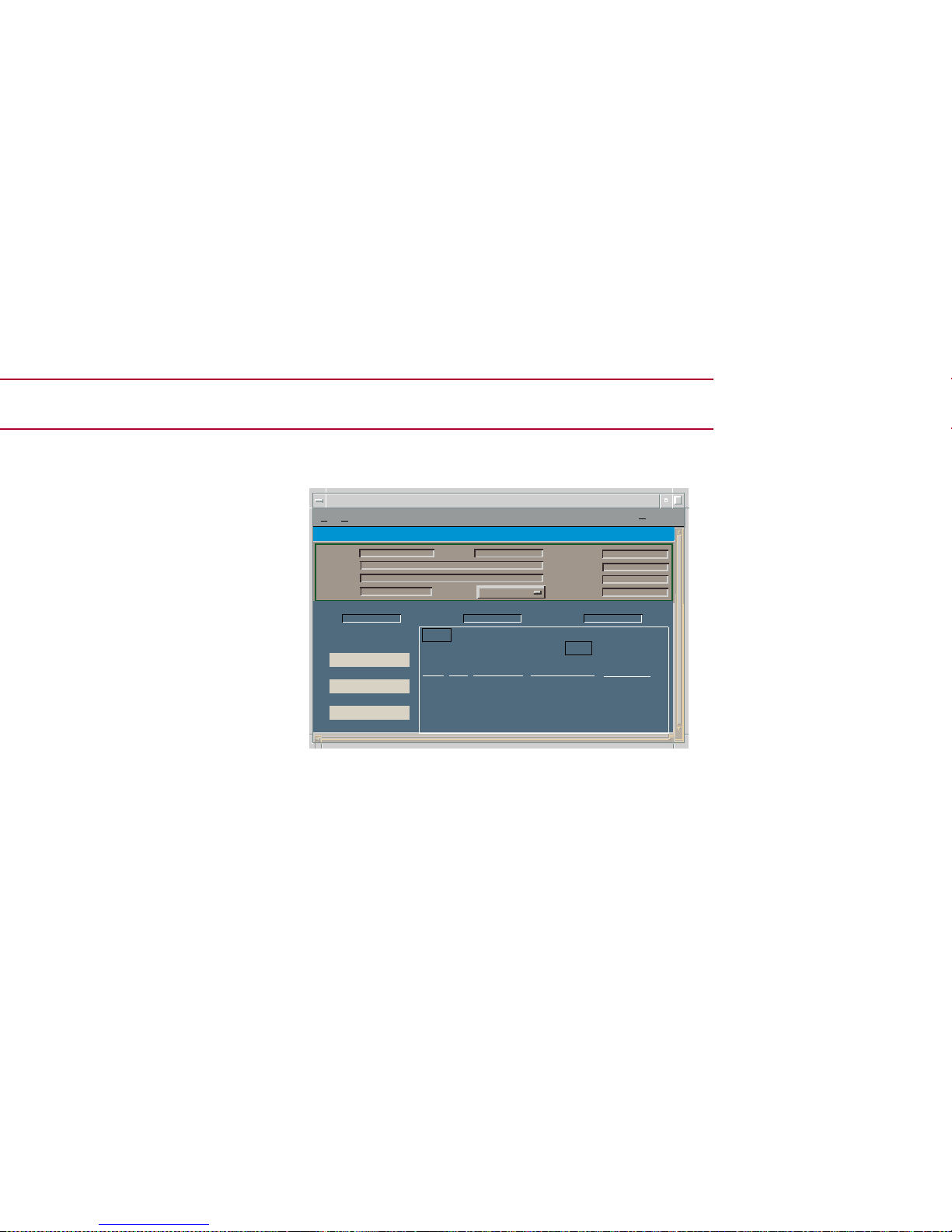
Figure 15: Device Configuration View
Device Configuration View
Access: From the Icon Subviews menu the
SmartSwitch 6000 Device icon, select Configuration.
*
F
ile View
H
elp
IP Address of type 6E132_25 of Landscape VNMHost: Primary
Model
Contact
Description
Location
Net Addr
Prime-App
SysUp Time
Manufacturer
DeviceT ype
SerialNumber
Device Name ContactStatus No. Interfaces
Device Configuration View
Index Type Phy Address Max Frame Size
Oper Status
Interface Configuration Table
Number ofInterfaces
Print
ComponentTable
DownLoad Application
Tra p Table
Page 47

Opens a dialog box that lets you set up your
workstation to be notified of traps received and
sent by a module.
Interface Configuration Table
This section of the Device Configuration views
provides the following information:
Number of Interfaces
The number of interfaces available from the
module.
Index
The numerical value identifying the port.
Type
The type of hardware interface for the port.
Phy Address
The MAC address of the port.
Max Frame Size
The maximum frame size for the module.
Oper Status
The current operational state of the port (Up,
Down, or Testing).
Trap
Table
Page 48

FddiMAC D eviceConfiguration
View
Access: From the Icon Subviews menu f or the Chassis
Device views, select FIDDI Configuration, from the
Icon Subviews menu of the FddiMac Application icon,
select Configuration.
This view provides information on the
configuration and operating status of the
concentrator. The view is divided into two areas,
Station Configuration and SMT Information.
Station Configuration
This area of the FddiMAC Device Configuration
view provides information specific to the FDDI
station.
Ring State
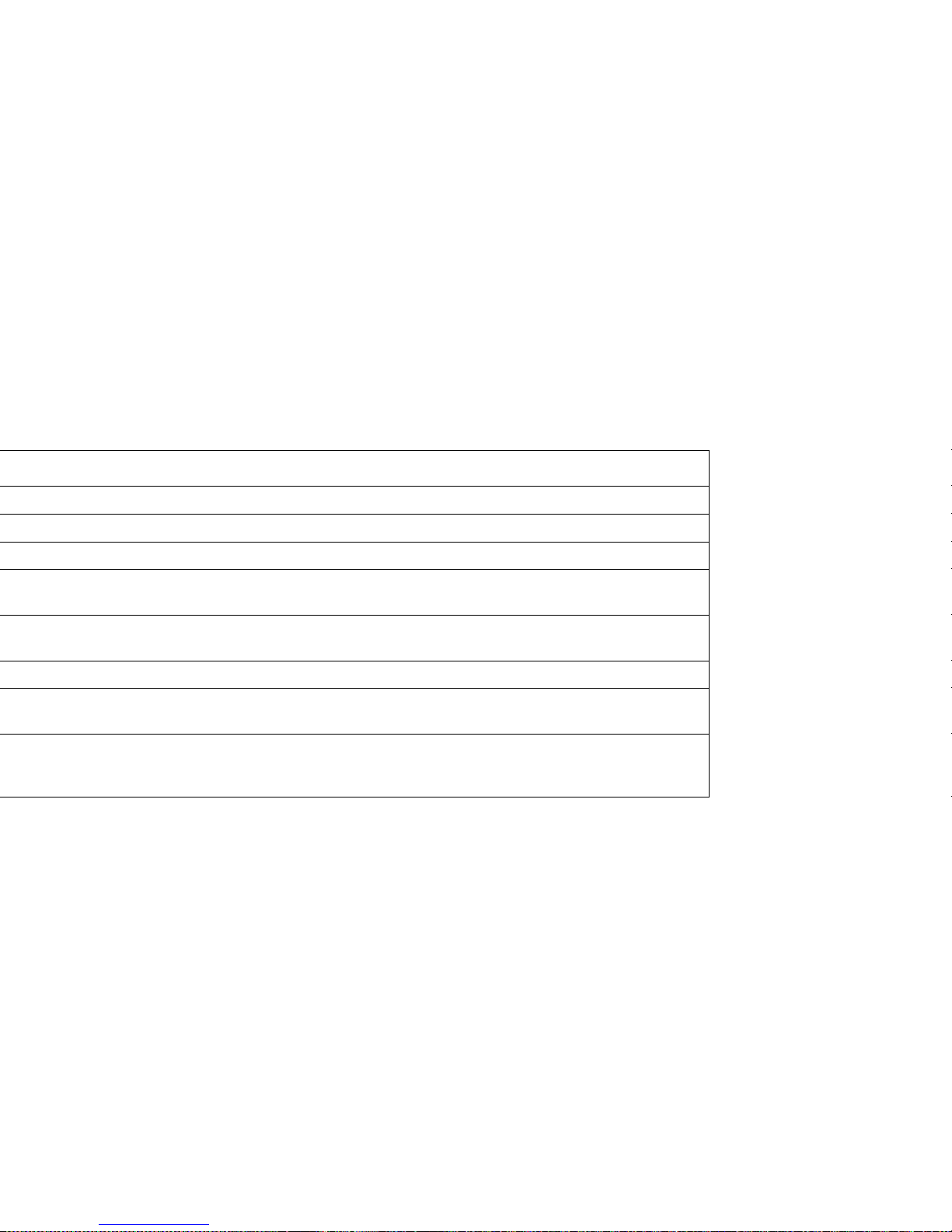
The current state of the FDDI ring. Table 20 lists
the possible states and their descriptions.
MAC Configuration
Displays the actual configuration of the station.
Table 21 lists the possible configuration states and
their descriptions.
Current MAC Path
The ring that this station resides on. Possible
values are Primary, Secondary, Local, or Isolated.
Page 49
Non Master Ports
The number of non-master ports on this station.
Master Ports
The number of master ports on this station.
Table 20: FDDI Ring Stats
Page 50
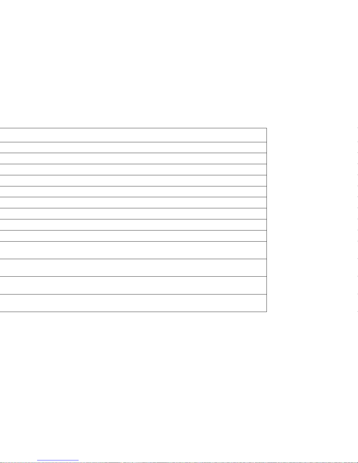
Table 21: SMT MAC Configuration States
Page 51

ATM Client Configuration View
This view provides VPI/VPC configuration
information on the ATM interfaces.
Max VPCs (Virtual Path Connections)
The maximum number of VPCs supported at this
ATM interface. At the UNI (User Network
Interface), the maximum number of VPCs ranges
from 0 to 256.
Max VCCs (Virtual Channel Connections)
The maximum number of VCCs supported at this
ATM interface.
Conf VPCs
The number of VPCs configured for use at this
ATM interface. At the UNI (User Network
Interface), the configured number of VPCs ranges
from 0 to 256.
Conf VCCs
The number of VCCs configured for use at this
ATM interface.
Max VPI (Virtual Path Identifier) Bits
The maximum number of active VPI bits
configured for use at this ATM interface. At the
UNI (User Network Interface), the maximum
number of active VPI bits configured for use
ranges from 0 to 8.
Page 52

Management Station can send SNMP messages as
IP datagrams to UDP port 161 in order to access
network management information concerning the
operation of that system.
Neighbor If Name
The name of the interface on the neighbor system
at the far end of this interface, and to which this
interface connects. If the neighbor system is
manageable through SNMP and supports the
object ifName, the value of this object must be
identical to that of the ifName for the ifEntry of
the lowest level physical interface for this port. If
this interface does not have a name, the value of
this object is a zero length string.
Page 53
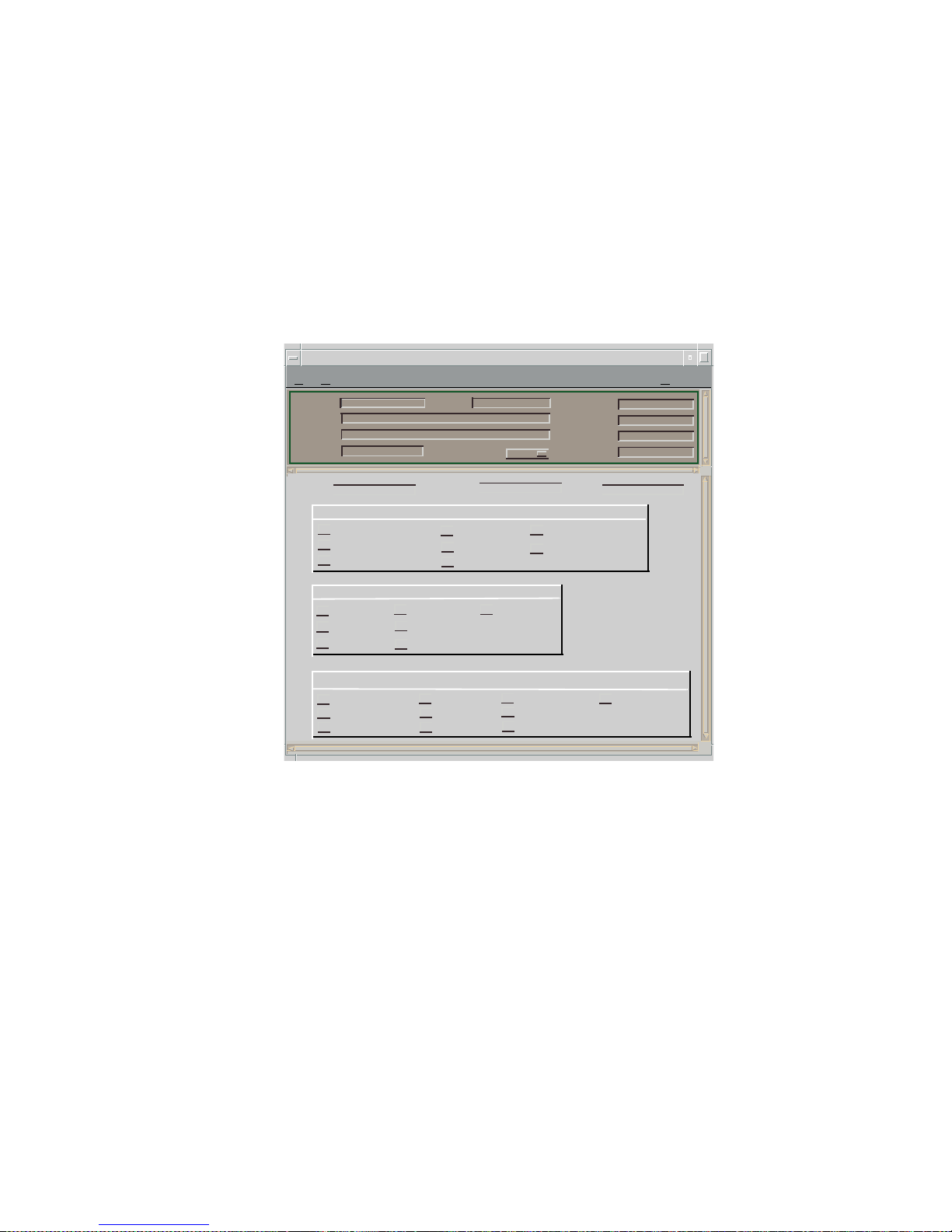
Figure 16: Fast Ethernet Configuration View
Operational Mode
This panel, in the Fast Ethernet Configuration
view, shows the current operational mode of this
port. If you select Auto-Negotiation, you can
select as many modes as needed from the
File View Help
132.127.118.24 of type 6E122_26 of Landscape
Model Name
Contact
Description
Location
Net Addr
SysUp Time
Manufacturer
Device Type
Serial Number
Primary Applica-
Cabletron 6E122_26 Rev 01.01.04 SmartSwitch
132.127.118.24
Interface
Port Group
Port
Operational Mode
Advertised Ability
Received Technology
Auto-Negotiation
10BaseT
10BaseTFD
100BaseTX
100BaseTXFD
100BaseT4
100BaseFX
100BaseFXFD
10BaseT
10BaseTFD
100BaseTX
100BaseTXFD
100BaseT4
100BaseFX
100BaseFXFD
Undefined
Auto-Negotiation
Not-Detected
10BaseT
10BaseTFD
100BaseTX
100BaseTXFD
100BaseT4
100BaseFX
100BaseFXFD
Page 54
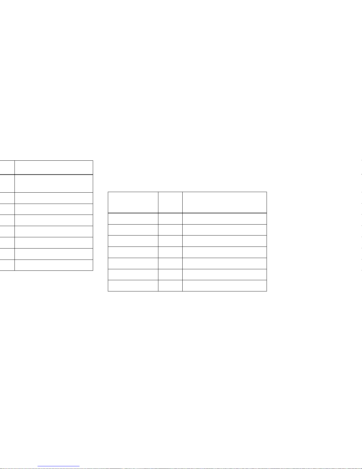
can also dynamically configure themselves for
Full Duplex or Half Duplex (standard mode)
operation when both ends of the link support
auto-negotiation. When only one link partner
supports auto-negotiation, the mode defaults to
half duplex. Table 23 lists the advertised ability
modes, their values, and descriptions.
Table 23: Advertised Ability Values
Received Technology
This panel, in the Fast Ethernet Configuration
view, shows the received technology of the remote
hardware, or link partner. Table 24 lists the
received technology modes, their values, and
descriptions. These modes are read only.
Detect.
Advertised
Ability
Va lue Description
10Base-T 8 10Base-T
10Base-TFD 16 Full Duplex 10Base-T
100Base-TX 32 100Base-TX
100Base-TXFD 64 Full Duplex 100Base-TX
100Base-T4 128 100Base-T4
100Base-FX 256 100Base-FX
100Base-FXFD 512 Full Duplex 100Ba se - FX
Page 55
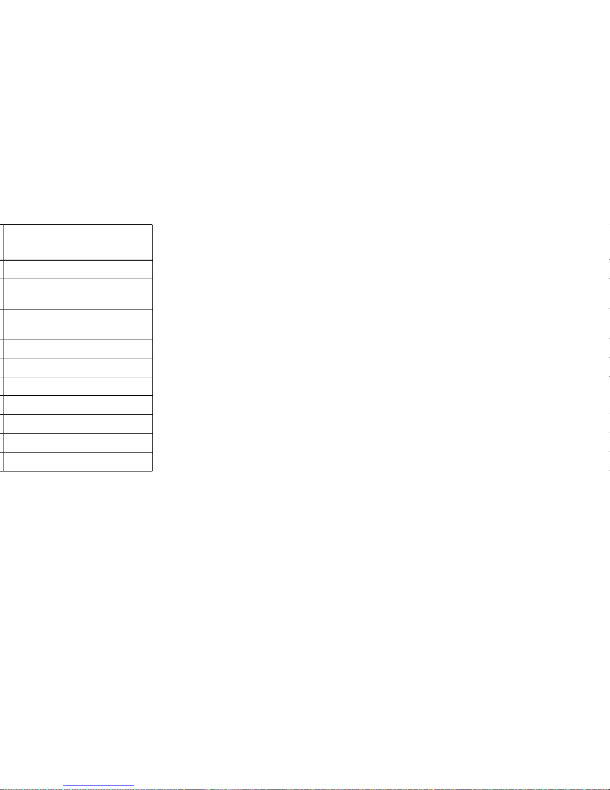
status of the selected repeater interface. This view
is divided into the four areas described below
(Repeater Management, Trap Management,
Alarm Configuration, and Error Source).
Repeater Management
This area of the Repeater Configuration view
provides the port information described below.
Port Count
Displays the total number of ports on this LAN
segment.
Ports On
Displays the total number of ports currently in
the ON state on this network.
Ports Operational
Displays the number of operational ports on this
network.
Network Ports
Allows you to enable the network ports on this
network segment. Possible states are: “NoEnable”
and “Enable”.
Detection
Auto-Negotiation
Page 56

Traffic Alarms
Allows you to enable or disable detection of Traffic
Alarms.
T raffic Threshold
Displays the threshold value for the number of
packets that can be transmitted during the
Timebase before generating a traffic alarm. This
field is user-configurable from 1 to 4 billion.
Collision Alarms
Allows you to enable or disable detection of
Collision Alarms.
Collision Threshold
Displays the threshold value within the alarm
timebase which, once that number of collisions
per good packet is exceeded, generates a collision
alarm. This value is user-configurable. Allowable
range is 1 to 15 collisions per good packet.
Broadcast Alarms
Allows you to enable or disable detection of
Broadcast Alarms.
Broadcast Threshold
Displays the threshold value within the alarm
timebase which, once that number of broadcasts
received is exceeded, generates a broadcast
alarm. This value is user-configurable. Allowable
range is 1 to ~4 billion.
Page 57

No_Resource
The number of times the module ran out of
resources (i.e., lack of buffer space) and could not
accept packets.
Giants
Packets received that exceed 1518 bytes (not
including preamble).
Ethernet Based Configuration
Access: From the Chassis Icon, select Ethernet Based
Configuration.
This view provides port configuration information
for GPIM models. This view also shares fields with
the Fast Ethernet Configuration View (page 54)
and the shared fields are covered there. The fields
below detail the device specific information found
with this view.
Auto Negotiate Mode
Indicates whether Auto-Negotiation is enabled for
a specific port. If Auto-Negotiation is disabled the
port will revert to the speed, duplex, and flow
control settings specified by their associated
leaves in the Flow Control groups.
Remote Auto Signal
Indicates whether the remote end of the link is
operating in Auto-Negotiation signaling or not.
Page 58

Page 59
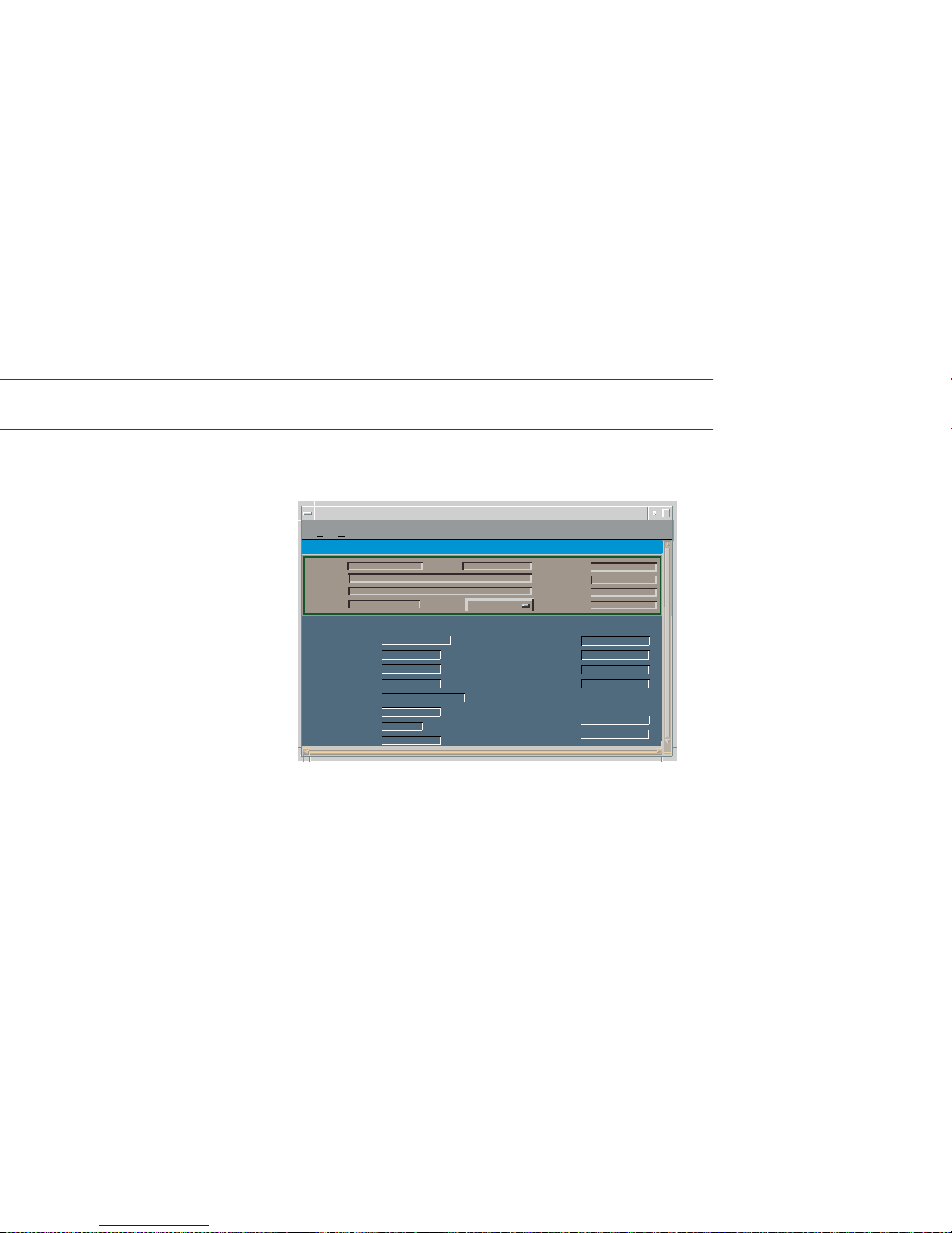
Model Information View
Figure 17: Model Information View
*
File View
H
elp
IP Address of type 6E132_25 of Landscape VNMHost: Primary
Model Name
Contact
Description
Location
Net Addr
Prime-App
Sys Up Time
Manufacturer
DeviceType
Serial Number
MM Version Number
MM Name
MM Part Number
Model Information View
General Information
CommunicationInformation
Community Name
DCM T imeOut
DCM Re tr y
Poll/Log Information
Model Created By
Model Type
ModelCreationTime
Poll Interval
Polling Status
Model State
Security String
Mgmnt Protocol
Page 60
Modeling
Autodiscovery involves manually modeling a seed
router, bridge, or switch (if such a model does
exist) and then running AutoDiscovery one or
more times to complete the network model. You
then refine your autodiscovered network model to
improve management capabilities.
The manual modeling procedures described in
this section should be used when making minor
changes to the network. This includes such
actions as placing an already discovered module
in Mixed Management mode or adding a new
chassis or module to the network.
Note:
Note:
Refer to Getting Started with
SPECTRUM for Administrators and
How to Manage Your Network with
SPECTRUM for instructions on using
AutoDiscovery and refining your
network model.
Page 61

the chassis Device icon in the Find view.
Access the Find you by selecting View>New
View> Find. Select an attribute by which you
can search for your Chassis. Create a Room
Location view and copy the chassis Device
icon into the Room Location view.
Container View
Access: From the Icon Subviews men for the Chassis
Device icon, select Container.
This view (Figure 18) displays Location view
Device icons for each module modeled in
SPECTRUM and contained in the chassis.
Note:
Note:
This only works when models are in
the distributed mode.
Page 62
Preparation for Modeling
Before modeling the chassis, you should be
familiar with the process of creating models and
accessing views. Refer to Getting Started with
SPECTRUM for Administrators and How to
Manage Your Network with SPECTRUM for
instructions. You should also be familiar with any
network management and firmware requirements
described in the 6C105 chassis firmware
documentation.
Modeling Using the Chassis IP
The chassis model can only be place in a Room
Location view. The Room Location view is created
by starting at the Universe level view and navigate
into the Room Location level, as described below.
1 At the Universe level, select View > New View
> Location.
This places you at the top level of the Location
views.
Model Three
6E233_49
6H122_16
Caution:
Caution:
For proper modeling, the chassis and its
installed modules must not be in Mixed
Management mode. Each module should
have its own IP address or the chassis
should be configured with a single IP
address.
Page 63
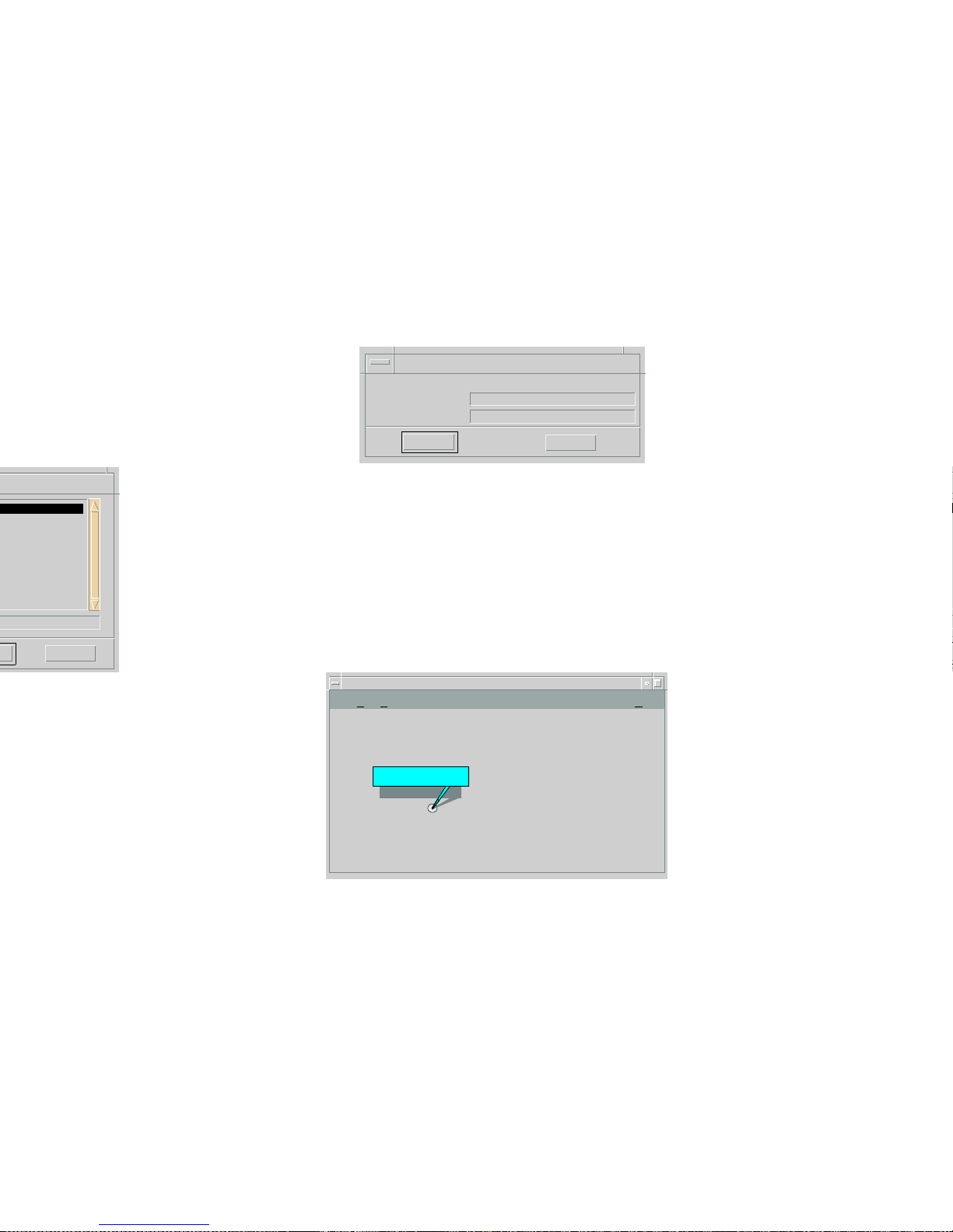
Figure 20: Creating Building Dialog Box
4 Enter the Building name and a Security
String (optional) and click OK.
The Building icon appears in the Building
Location view (Figure 21).
Figure 21: Building Location View
Cancel
Creating Building
Cancel
OK
Please enter:
Building Name
Security String
* File Edit Help
Building Name
Primary Landscape 0x00400000 - VNM Host -
Page 64

15 Exit the Edit mode when the chassis Device
icon appears in the Room Location view.
New Model By IP Option
This option for modeling a module or chassis
proceeds as follows:
1 In the appropriate Topology view, select File >
Edit to place the view in the Edit mode.
2 Select Edit > New Model By IP.
The Select Model Type dialog box displays,
3 Enter the IP address assigned to the module.
4 Enter the Community Name that has been
assigned locally to the module. The default
Community Name value is “public.”
5 Click OK.
SPECTRUM places the Device icon
representing the module at the top of the
Topology view.
6 Select File > Close Edit to exit the Edit mode.
Note:
Note:
See your network administrator to verify
that the Community Name has not been
changed from “public” to another access
policy name.
Page 65

f Exit the Edit mode.
Page 66

Index
B
Backplane
Connection Status
35
Connections 32, 35
Information 32, 34
Basic Alarms 23
Beacon 50
Bridge
Application Status
25
Detail 24
Model Information 24
Performance 24
Broadcast
Alarms
57
Threshold 57
C
C_Wrap
A
51
B 51
S 51
Chassis 10
Chassis Information 21, 29
Chassis Modul e Icon 22
Claim/Beacon Process 50
Collision Threshold 57
Community
Name
48
String 54
Concentrator, Isolated 50
Configuring Ports 54
Contact Status 48
Cooling Fans Information 29
CRC 58
Current MAC Path 49
Cyclical Redundancy Checks 58
D
Detect, Ring State 50
Device
Information
22
DevTop View 23, 37
Directed 50
E
Error Source 58
Page 67

Information 25, 30
Number 31
Status 25
Type 25, 49
Isolated 51
L
Labels and Icons 14
Local
A
51
AB 51
B 51
S 51
M
MAC
Address
32, 50
Configuration 49
Count 50
Management Tasks 15
Master Ports 50
Max
VCCs
52
VPCs 52
VPI Bits 52
Model
Information
23, 60
Name 23, 35
Type 23, 35
Types of 12
Monitoring Operation 16
N
Neighbor
Address
53
If Name 53
Notification Protocol 52
Upstream 50
Network Information 32
New Model By IP 65
No_Resource 58
Non Master Ports 50
Non-Op 50
Non-Op, Dup 50
O
OBS, Present 52
OOW_Colls 58
Oper Status 48
Operation Status 49
Operational Mod e 41
Optical Bypass Switch 52
Page 68

56
Status 26
Restricted Rights Notice 3
Ring
Operational
50
State 49
Ring-Op, Dup 50
Runt Packets 58
S
Slot Number 23, 35
SMT
Information
52
MAC Configuration 51
Version 52
Source Address Management 57
Spanning Tree Information 24
Static Database Table 24
Station Management 52
T
Target Token Rotation Time 52
Thru 51
Timebase 57
T-Neg 52
T-Notify 52
Token Rotation Time 52
Topology 37
Trace 50
Trademarks 3
Tra ffic Threshold 57
Transparent Bridge Info 24
Trap Configuration 57
T-Req 52
Troubleshooting 15
TTRT 52
TVX 52
Type of Hardware 48
U
Upgrading Firmware 16
Upstream Neighbor 50
V
Valid Transmission Time 52
VCCs 52
VCI Bits 53
VCL/VCI/VPI Information 42
Views 14
Virtual Channel Operation 17
Virtual Link
AAL Type
42, 45
Admin Status 42, 44
Communication Information 43
Create 44
Encaps Type 43, 45
Interface 44
Page 69

 Loading...