

Cabletron Systems 2H22-08R, SmartSwitch 2208 2H22-08R User Manual
2H22-08R
2H22-08R
SmartSwitch 2208
User’s Guide
Title Page
PWR
RESET
CPU
COM
216543
1X 5X 6X4X3X2X
7
8
9032385-02


Only qualified personnel should perform installation
procedures.
NOTICE
Cabletron Systems reserves the right to make changes in specifications and other information
contained in this document without prior notice. The reader should in all cases consult Cabletron
Systems to determine whether any such changes have been made.
The hardware, firmware, or software described in this manual is subject to change without notice.
IN NO EVENT SHALL CABLETRON SYSTEMS BE LIABLE FOR ANY INCIDENTAL,
INDIRECT, SPECIAL, OR CONSEQUENTIAL DAMAGES WHATSOEVER (INCLUDING BUT
NOT LIMITED TO LOST PROFITS) ARISING OUT OF OR RELATED TO THIS MANUAL OR
THE INFORMATION CONTAINED IN IT, EVEN IF CABLETRON SYSTEMS HAS BEEN
ADVISED OF, KNOWN, OR SHOULD HAVE KNOWN, THE POSSIBILITY OF SUCH
DAMAGES.
1998 by Cabletron Systems, Inc., P.O. Box 5005, Rochester, NH 03866-5005
All Rights Reserved
Printed in the United States of America
Order Number: 9032385-02 October 1998
Cabletron Systems, SPECTRUM, LANVIEW, QuickSet
trademarks
and
SmartSwitch is a
All other product names mentioned in this manual may be trademarks or registered trademarks of
their respective companies.
trademark of Cabletron Systems, Inc.
, and
ECUREFAST
S
are registered
FCC NOTICE
This device complies with Part 15 of the FCC rules. Operation is subject to the following two
conditions: (1) this device may not cause harmful interference, and (2) this device must accept any
interference received, including interference that may cause undesired operation.
NOTE:
device, pursuant to Part 15 of the FCC rules. These limits are designed to provide reasonable
protection against harmful interference when the equipment is operated in a commercial environment.
This equipment uses, generates, and can radiate radio frequency energy and if not installed in
accordance with the operator’s manual, may cause harmful interference to radio communications.
Operation of this equipment in a residential area is likely to cause interference in which case the user
will be required to correct the interference at his own expense.
WARNING:
party responsible for compliance could void the user’s authority to operate the equipment.
This equipment has been tested and found to comply with the limits for a Class A digital
Changes or modifications made to this device which are not expressly approv ed by the
2H22-08R SmartSwitch 2208 User’s Guide i

Notice
INDUSTRY CANADA NOTICE
This digital apparatus does not exceed the Class A limits for radio noise emissions from digital
apparatus set out in the Radio Interference Regulations of the Canadian Department of
Communications.
Le présent appareil numérique n’émet pas de bruits radioélectriques dépassant les limites applicables
aux appareils numériques de la class A prescrites dans le Règlement sur le brouillage radioélectrique
édicté par le ministère des Communications du Canada.
VCCI NOTICE
This is a Class A product based on the standard of the Voluntary Control Council for Interference by
Information Technology Equipment (VCCI). If this equipment is used in a domestic environment,
radio disturbance may arise. When such trouble occurs, the user may be required to take corrective
actions.
CABLETRON SYSTEMS, INC. PROGRAM LICENSE AGREEMENT
IMPORTANT:
This document is an agreement between you, the end user, and Cabletron Systems, Inc. (“Cabletron”)
that sets forth your rights and obligations with respect to the Cabletron software program (the
“Program”) contained in this package. The Program may be contained in firmware, chips or other
media. BY UTILIZING THE ENCLOSED PRODUCT, YOU ARE AGREEING TO BECOME
BOUND BY THE TERMS OF THIS AGREEMENT, WHICH INCLUDES THE LICENSE AND
THE LIMITATION OF WARRANTY AND DISCLAIMER OF LIABILITY. IF YOU DO NOT
AGREE TO THE TERMS OF THIS AGREEMENT, PROMPTLY RETURN THE UNUSED
PRODUCT TO THE PLACE OF PURCHASE FOR A FULL REFUND.
Before utilizing this product, carefully read this License Agreement.
ii 2H22-08R SmartSwitch 2208 User’s Guide

CABLETRON SOFTWARE PROGRAM LICENSE
Notice
1. LICENSE
package subject to the terms and conditions of this License Agreement.
You may not copy, reproduce or transmit any part of the Program except as permitted by the
Copyright Act of the United States or as authorized in writing by Cabletron.
2. OTHER RESTRICTIONS. You may not reverse engineer, decompile, or disassemble the
Program.
3. APPLICABLE LA W. This License Agreement shall be interpreted and governed under the laws
and in the state and federal courts of New Hampshire. You accept the personal jurisdiction and
venue of the New Hampshire courts.
. You have the right to use only the one (1) copy of the Program provided in this
EXCLUSION OF WARRANTY AND DISCLAIMER OF LIABILITY
1. EXCLUSION OF
writing, Cabletron makes no warranty, expressed or implied, concerning the Program (including
its documentation and media).
CABLETRON DISCLAIMS ALL WARRANTIES, OTHER THAN THOSE SUPPLIED TO
YOU BY CABLETRON IN WRITING, EITHER EXPRESSED OR IMPLIED, INCLUDING
BUT NOT LIMITED TO IMPLIED WARRANTIES OF MERCHANTABILITY AND
FITNESS FOR A PARTICULAR PURPOSE, WITH RESPECT TO THE PROGRAM, THE
ACCOMPANYING WRITTEN MA TERIALS, AND ANY A CCOMPANYING HARDW ARE.
WARRANTY. Except as may be specifically provided by Cabletron in
2. NO LIABILITY FOR CONSEQUENTIAL DAMAGES. IN NO EVENT SHALL
CABLETRON OR ITS SUPPLIERS BE LIABLE FOR ANY DAMAGES WHATSOEVER
(INCLUDING, WITHOUT LIMITATION, DAMAGES FOR LOSS OF BUSINESS,
PROFITS, BUSINESS INTERRUPTION, LOSS OF BUSINESS INFORMATION, SPECIAL,
INCIDENTAL, CONSEQUENTIAL, OR RELIANCE DAMAGES, OR OTHER LOSS)
ARISING OUT OF THE USE OR INABILITY TO USE THIS CABLETRON PRODUCT,
EVEN IF CABLETRON HAS BEEN ADVISED OF THE POSSIBILITY OF SUCH
DAMAGES. BECAUSE SOME STATES DO NOT ALLOW THE EXCLUSION OR
LIMITATION OF LIABILITY FOR CONSEQUENTIAL OR INCIDENTAL DAMAGES, OR
ON THE DURATION OR LIMITATION OF IMPLIED WARRANTIES, IN SOME
INSTANCES THE ABOVE LIMITATIONS AND EXCLUSIONS MAY NOT APPLY TO
YOU.
UNITED STATES GOVERNMENT RESTRICTED RIGHTS
The enclosed product (a) was developed solely at private expense; (b) contains “restricted computer
software” submitted with restricted rights in accordance with Section 52227-19 (a) through (d) of the
Commercial Computer Software - Restricted Rights Clause and its successors, and (c) in all respects
is proprietary data belonging to Cabletron and/or its suppliers.
For Department of Defense units, the product is licensed with “Restricted Rights” as defined in the
DoD Supplement to the Federal Acquisition Regulations, Section 52.227-7013 (c) (1) (ii) and its
successors, and use, duplication, disclosure by the Government is subject to restrictions as set forth in
subparagraph (c) (1) (ii) of the Rights in Technical Data and Computer Software clause at
252.227-7013. Cabletron Systems, Inc., 35 Industrial Way, Rochester, New Hampshire 03867-0505.
2H22-08R SmartSwitch 2208 User’s Guide iii

Notice
SAFETY INFORMATION
CLASS 1 LASER TRANSCEIVERS
THE FE-100F3 FAST ETHERNET INTERFACE MODULE, FPIM-05 AND
FPIM-07 FDDI PORT INTERFACE MODULES, AND APIM-29 ATM
PORT INTERFACE MODULE USE CLASS 1 LASER TRANSCEIVERS.
READ THE FOLLOWING SAFETY INFORMATION BEFORE
INSTALLING OR OPERATING THESE MODULES.
The Class 1 laser transceivers use an optical feedback loop to maintain Class 1 operation limits. This
control loop eliminates the need for maintenance checks or adjustments. The output is factory set, and
does not allow any user adjustment. Class 1 Laser transceivers comply with the following safety
standards:
• 21 CFR 1040.10 and 1040.11 U.S. Department of Health and Human Services (FDA).
• IEC Publication 825 (International Electrotechnical Commission).
• CENELEC EN 60825 (European Committee for Electrotechnical Standardization).
When operating within their performance limitations, laser transceiver output meets the Class 1
accessible emission limit of all three standards. Class 1 levels of laser radiation are not considered
hazardous.
SAFETY INFORMATION
CLASS 1 LASER TRANSCEIVERS
LASER RADIATION AND CONNECTORS
When the connector is in place, all laser radiation remains within the fiber. The maximum amount of
radiant power exiting the fiber (under normal conditions) is -12.6 dBm or 55 x 10-6 watts.
Removing the optical connector from the transceiver allows laser radiation to emit directly from the
optical port. The maximum radiance from the optical port (under worst case conditions) is
0.8 W cm-2 or 8 x 10³ W m2 sr-1.
Do not use optical instruments to view the laser output. The use of optical instruments to view
laser output increases eye hazard. When viewing the output optical port, power must be
removed from the network adapter.
iv 2H22-08R SmartSwitch 2208 User’s Guide

DECLARATION OF CONFORMITY
Notice
Application of Council Directive(s):
Manufacturer’s Name:
Manufacturer’ s Address:
European Representative Name:
European Representative Address:
Conformance to Directive(s)/Product Standards:
Equipment Type/Environment:
89/336/EEC
73/23/EEC
Cabletron Systems, Inc.
35 Industrial Way
PO Box 5005
Rochester, NH 03867
Mr. J. Solari
Cabletron Systems Limited
Nexus House, Newbury Business Park
London Road, Newbury
Berkshire RG13 2PZ, England
EC Directive 89/336/EEC
EC Directive 73/23/EEC
EN 55022
EN 50082-1
EN 60950
Networking Equipment, for use in a
Commercial or Light
Environment.
Industrial
We the undersigned, hereby declare, under our sole responsibility, that the equipment packaged
with this notice conforms to the above directives.
Manufacturer Legal Representative in Europe
Mr. Ronald Fotino Mr. J. Solari
___________________________________ ___________________________________
Full Name Full Name
Principal Compliance Engineer Managing Director - E.M.E.A.
___________________________________ ___________________________________
Title Title
Rochester, NH, USA Newbury, Berkshire, England
___________________________________ ___________________________________
Location Location
2H22-08R SmartSwitch 2208 User’s Guide v

Notice
vi 2H22-08R SmartSwitch 2208 User’s Guide

CONTENTS
CHAPTER 1 INTRODUCTION
1.1 Using This Guide.........................................................................1-1
1.2 Structure of This Guide................................................................1-1
1.3 2H22-08R Overview....................................................................1-3
1.3.1 Auto-Negotiation.............................................................1-3
1.3.2 Connectivity ....................................................................1-4
1.3.3 Runtime IP Address Discovery.......................................1-4
1.3.4 Remote Monitoring (RMON)...........................................1-5
1.3.5 Switching Options...........................................................1-5
1.3.6 Standards Compatibility..................................................1-5
1.3.7 Year 2000 Compliant......................................................1-5
1.3.8 LANVIEW Diagnostic LEDs............................................1-5
1.4 Local Management......................................................................1-6
1.4.1 Broadcast Suppression................................................... 1-6
1.4.2 Port Redirect Function....................................................1-7
1.4.3 Full Duplex Switched Ethernet (FDSE)........................... 1-7
1.4.4 SmartTrunk.....................................................................1-7
1.5 Optional Features........................................................................1-8
1.6 Document Conventions...............................................................1-9
1.7 Getting Help...............................................................................1-10
1.8 Related Manuals........................................................................1-11
CHAPTER 2 NETWORK REQUIREMENTS
2.1 SmartTrunk..................................................................................2-1
2.2 10BASE-T Network .....................................................................2-1
2.3 100BASE-TX Network.................................................................2-2
2.4 100BASE-FX Fiber Optic Network ..............................................2-2
CHAPTER 3 INSTALLATION
3.1 Required Tools............................................................................3-1
3.2 Unpacking the 2H22-08R............................................................3-2
3.3 Installing Options.........................................................................3-2
3.4 Installing the 2H22-08R...............................................................3-3
3.4.1 Tabletop and Shelf Installations...................................... 3-3
3.4.2 Rackmount Installation ...................................................3-4
3.5 Connecting Power to the 2H22-08R............................................3-6
2H22-08R SmartSwitch 2208 User’s Guide vii

CONTENTS
3.6 Connecting to the Network...........................................................3-7
3.6.1 Connecting a Twisted Pair Segment to the FE-100TX....3-8
3.6.2 Connecting a Fiber Optic Segment to the
FE-100FX and FE-100F3..............................................3-10
3.7 Completing the Installation.........................................................3-12
CHAPTER 4 TROUBLESHOOTING
4.1 Using LANVIEW...........................................................................4-1
4.2 FE-100TX LED.............................................................................4-3
4.3 Troubleshooting Checklist............................................................4-4
4.4 Using the RESET Button .............................................................4-6
CHAPTER 5 LOCAL MANAGEMENT
5.1 Overview......................................................................................5-1
5.2 Local Management Keyboard Conventions.................................5-2
5.3 Management Terminal Setup.......................................................5-3
5.3.1 Console Cable Connection..............................................5-4
5.3.2 Uninterruptible Power Supply Monitoring........................5-5
5.3.3 Management Terminal Setup Parameters ......................5-6
5.3.4 Telnet Connections .........................................................5-7
5.4 Accessing Local Management.....................................................5-8
5.4.1 Navigating Local Management Screens..........................5-9
5.4.2 Selecting Local Management Menu Screen Items........5-11
5.4.3 Exiting Local Management Screens..............................5-11
5.5 Device Menu Screen..................................................................5-12
5.6 Device Configuration Menu Screen ...........................................5-14
5.7 General Configuration Screen ...................................................5-16
5.7.1 Setting the IP Address...................................................5-19
5.7.2 Setting the Subnet Mask...............................................5-20
5.7.3 Setting the Default Gateway..........................................5-22
5.7.4 Setting the TFTP Gateway IP Address .........................5-23
5.7.5 Setting the Device Date.................................................5-24
5.7.6 Setting the Device Time................................................5-24
5.7.7 Entering a New Screen Refresh Time...........................5-25
5.7.8 Setting the Screen Lockout Time..................................5-25
5.7.9 Setting the Operational Mode........................................5-26
5.7.10 Configuring the COM Port.............................................5-27
5.7.11 Clearing NVRAM...........................................................5-30
5.8 SNMP Community Names Screen.............................................5-32
5.8.1 Establishing Community Names ...................................5-33
5.9 SNMP Traps Screen..................................................................5-35
5.9.1 Configuring the Trap Table............................................5-36
viii 2H22-08R SmartSwitch 2208 User’s Guide

CONTENTS
5.10 Switch Configuration Screen.....................................................5-37
5.10.1 Setting the STA............................................................. 5-40
5.10.2 Setting the Age Time ....................................................5-41
5.10.3 Setting (Enabling or Disabling) the Port Status ............5-41
5.11 Ethernet Interface Configuration................................................5-42
5.11.1 Configuring an FE-100TX Interface..............................5-44
5.11.2 Setting the FE-100TX Operational Mode...................... 5-45
5.11.3 Setting the FE-100TX Advertised Ability.......................5-45
5.11.4 Configuring an FE-100FX or FE-100F3
Interface for Port 7 or 8.................................................5-46
5.11.5 Setting the FE-100FX and FE-100F3
in Operational Mode .....................................................5-46
5.11.6 Setting the Flow Control Admin Status.........................5-47
5.12 Device Specific Configuration Menu..........................................5-48
5.13 System Resources Screen........................................................5-50
5.13.1 Setting the Reset Peak Utilization ................................5-51
5.14 Flash Download Screen ............................................................5-52
5.14.1 Image File Download Using BootP...............................5-55
5.14.2 Image File Download Using TFTP................................ 5-55
5.14.3 Image File Download Using RUNTIME ........................5-56
5.15 Port Redirect Function Screen ..................................................5-57
5.15.1 Displaying the Source and Destination Entries............. 5-59
5.15.2 Changing Source and Destination Ports....................... 5-60
5.15.3 Changing the Remap Errors Field ................................5-61
5.16 Broadcast Suppression Screen.................................................5-62
5.16.1 Setting the Threshold.................................................... 5-63
5.16.2 Setting the Reset Peak.................................................5-64
5.17 Device Statistics Menu Screen..................................................5-65
5.18 Switch Statistics Screen............................................................5-67
5.19 Interface Statistics Screen.........................................................5-69
5.19.1 Displaying Interface Statistics.......................................5-72
5.19.2 Using the Clear Counters Command............................ 5-73
5.20 RMON Statistics Screen............................................................5-74
5.20.1 Displaying RMON Statistics.......................................... 5-78
5.20.2 Using the Clear Counters Command............................ 5-78
5.21 Network Tools............................................................................5-79
5.21.1 Built-in Commands .......................................................5-81
5.21.2 Special Commands.......................................................5-92
2H22-08R SmartSwitch 2208 User’s Guide ix

CONTENTS
APPENDIX A SPECIFICATIONS
A.1 Device Specifications.................................................................. A-1
A.2 Physical Properties ..................................................................... A-1
A.3 Electrical Specifications .............................................................. A-1
A.4 Environmental Requirements...................................................... A-2
A.5 Input/Output Ports....................................................................... A-2
A.6 COM Port Pinout Assignments ................................................... A-2
A.7 Regulatory Compliance............................................................... A-3
APPENDIX B FE-100TX, FE-100FX, AND FE-100F3
SPECIFICATIONS
B.1 FE-100TX.................................................................................... B-1
B.2 FE-100FX.................................................................................... B-2
B.3 FE-100F3.................................................................................... B-3
APPENDIX C OPTIONAL INSTALLATIONS AND
MODE SWITCH BANK SETTINGS
C.1 Required Tools............................................................................C-1
C.2 Removing the Chassis Cover .....................................................C-2
C.2.1 Setting the Mode Switch.................................................C-5
C.3 Installing Optional Fast Ethernet Interface Modules ...................C-7
INDEX
x 2H22-08R SmartSwitch 2208 User’s Guide

CHAPTER 1
INTRODUCTION
Welcome to the Cabletron Systems
User’s Guide
. This guide provides the necessary documentation to install
2H22-08R SmartSwitch 2208
and operate the 2H22-08R SmartSwitch 2208 standalone device and
provides information concerning network requirements, installation,
troubleshooting, and the use of Local Management.
1.1 USING THIS GUIDE
Read through this guide completely to understand the 2H22-08R device
features, capabilities, and Local Management functions. A general
working knowledge of Ethernet and IEEE 802.3 type data
communications networks and their physical layer components is helpful
when using this device.
In this document, the 2H22-08R standalone device is referred
NOTE
to as either the “2H22-08R” or the “standalone.”
1.2 STRUCTURE OF THIS GUIDE
This guide is organized as follows:
Chapter 1, Introduction
briefly describes the 2H22-08R features. Directions about how to obtain
additional help and a list of related manuals are also included.
Chapter 2, Network Requirements
to consider before installing the 2H22-08R.
Chapter 3, Installation
2H22-08R and connect segments to the device.
Chapter 4, Troubleshooting
LEDs, which can help to quickly diagnose network/operational problems.
Chapter 5, Local Management
Management to configure and manage the 2H22-08R.
, outlines the contents of this manual, and
, explains the network requirements
, provides instructions on how to install the
, describes the function of the LANVIEW
, describes how to access Local
2H22-08R SmartSwitch 2208 User’s Guide Page 1-1

Chapter 1:
Introduction
Appendix A, Specifications
, contains information on functionality and
operating specifications, connector pinouts, environmental requirements,
and physical properties.
Appendix B, FE-100TX, FE-100FX, and FE-100F3 Specifications
,
contains information about FE-100TX pinouts and information
concerning cable types used with the FE-100FX and FE100-F3.
Appendix C, Optional Installations and Mode Switch Bank Settings
,
describes how to install optional Fast Ethernet Interf ace Modules and how
to set the mode switches.
Page 1-2 2H22-08R SmartSwitch 2208 User’s Guide
2H22-08R Overview
1.3 2H22-08R OVERVIEW
The 2H22-08R is a Fast Ethernet standalone device that has six RJ45
switched ports and two optional Fast Ethernet Interface Module ports
(100BASE-TX, 100BASE-FX, and 100BASE-F3) that provide twisted
pair, multimode, and single mode fiber optic cabling connectivity.
PWR
RESET
2H22-08R
The 2H22-08R supports traditional IEEE 802.1d switching (bridging),
IEEE 802.Q switching, and Cabletron Systems S
Virtual Network technology. The 2H22-08R is used to connect individual
high-bandwidth user devices, such as workstations, and provide a central
switching point for multiple 10/100 Mbps Fast Ethernet segments.
CPU
COM
216543
1X 5X 6X4X3X2X
7
8
Figure 1-1 The 2H22-08R
ECUREFAST
Switching
1.3.1 Auto-Negotiation
Twisted Pair ports on the 2H22-08R can auto-negotiate the type of
connection required to provide a link to another device. During
Auto-Negotiation, two devices automatically exchange information
concerning their operating capabilities. The Auto-Negotiation feature
targets the maximum capabilities between the two devices. For example,
the 2H22-08R adjusts to 100 Mbps when the device on the other end of
the connection can adjust between 10 Mbps or 100 Mbps. If the device on
the other end of the connection can only operate at 10 Mbps, then the
2H22-08R adjusts to 10 Mbps operation.
When Auto-Negotiation is supported at both ends of a link, the two
devices dynamically adjust to full or half duplex operation based on the
maximum capability that can be reached between the two devices. If the
device connected to the 2H22-08R cannot auto-negotiate, the 2H22-08R
interface operates according to the capabilities of the other device.
2H22-08R SmartSwitch 2208 User’s Guide Page 1-3

Chapter 1:
Introduction
1.3.2 Connectivity
The 2H22-08R connects to Ethernet networks or workstations through six
RJ45 ports on the front panel. These ports support Category 5 unshielded
and shielded twisted pair cables of lengths up to 100 meters. These ports
are IEEE 802.3u 100BASE-TX compliant.
The 2H22-08R has two front panel slots (ports 7 and 8) for optional Fast
Ethernet Interface Modules (FE-100TX, FE-100FX, and FE-100F3) to
support an uplink to 100 Mbps Fast Ethernet backbones or a high speed
connection to a local server using twisted pair , multimode or single mode
fiber optic cabling.
1.3.3 Runtime IP Address Discovery
This feature enables the 2H22-08R to automatically accept an IP address
from a Boot Strap Protocol (BootP) server on the network into NVRAM
without requiring a user to enter an IP address through Local
Management.
When the 2H22-08R is connected to the network and powered up,
Runtime IP Address Discovery (RAD) checks the 2H22-08R for an IP
address. If one has not yet been assigned (2H22-08R IP address set to
0.0.0.0), RAD checks to see if any of the 2H22-08R interfaces hav e a link.
If so, RAD sends out Reverse Address Resolution Protocol (RARP) and
BootP requests to obtain an IP address from a BootP server on the
network.
The RAD requests start out at an interval of 1 second. The interval then
doubles after every transmission until an interval of 300 seconds is
reached. At this point, the interval remains at 300 seconds. The RAD
requests continue until an IP address is received from a BootP server, or
an IP address is entered using Local Management.
Page 1-4 2H22-08R SmartSwitch 2208 User’s Guide

2H22-08R Overview
1.3.4 Remote Monitoring (RMON)
The 2H22-08R supports all Ethernet RMON groups, which include
Statistics, Alarms, Events and History as the def ault groups enabled on all
ports, and Capture, Filter, and Host as the groups that are off by default.
Cabletron Systems RMON Actions is a vendor-specific extension of
RMON and provides the ability to set an “Action” on any SNMP MIB
variable. The Action can be triggered by any RMON Event and/or Alarm.
The Action can be, for example, to turn a MIB-2 interface off if a
broadcast threshold is crossed.
1.3.5 Switching Options
The 2H22-08R provides traditional Switching (802.1D), IEEE 802.1Q, or
S
ECUREFAST
panel interfaces including Fast Ethernet Interface Modules. S
Switching and IEEE 802.1Q allows for migration to Virtual Network
technologies without requiring the replacement of existing equipment.
Switching Virtual Network Services between all of the front
ECUREFAST
1.3.6 Standards Compatibility
The 2H22-08R provides IEEE 802.1, 802.1u, 802.1D and DEC Spanning
Tree Algorithm (STA) support to enhance the overall reliability of the
network and protect against “loop” conditions. The 2H22-08R supports a
wide variety of industry standard MIBs including RFC 1213 (MIB II),
RFC 1757 (RMON), RFC 1493 (Bridge MIB), and RFC 1354 (FIB MIB).
A full suite of Cabletron Systems Enterprise MIBs provides a wide array
of statistical information to enhance troubleshooting.
1.3.7 Year 2000 Compliant
The 2H22-08R has an internal clock that can maintain the current time
and date beyond the year 1999.
1.3.8 LANVIEW Diagnostic LEDs
The various conditions of the LANVIEW diagnostic LEDs serve as
important troubleshooting aids. They provide an easy way to observe the
transmit and receive status of individual ports and overall network
operations such as system status, switching configuration, and Fast
Ethernet channel usage.
LANVIEW LEDs.
Chapter 4
provides details about the 2H22-08R
2H22-08R SmartSwitch 2208 User’s Guide Page 1-5

Chapter 1:
Introduction
1.4 LOCAL MANAGEMENT
Management of the 2H22-08R is accomplished using Local Management
tools or remote Simple Network Management Protocol (SNMP)
management stations. Out-of-band Local Management is accessible
through the RS232 COM port on the front panel using a VT100 terminal,
or a remote VT100 terminal emulator via a modem connection, and
in-band via a Telnet connection. In-band remote management is possible
through any SNMP compliant Network Management Software.
Local Management provides the tools to manage the 2H22-08R, and its
two Fast Ethernet Interface Modules. It also allows the following tasks to
be performed:
•
Assign an IP address and subnet mask to the 2H22-08R.
•
Select a default gateway and default interface.
•
Control local and remote access.
•
Designate workstations to receive SNMP traps from the 2H22-08R.
Chapter 5
provides detailed information about Local Management of the
2H22-08R, and its two optional Fast Ethernet Interface Modules. Local
Management also provides the features detailed in Section 1.4.1 through
Section 1.4.4.
1.4.1 Broadcast Suppression
Broadcast Suppression allows a user to set a desired limit of receive
broadcast frames per port/per second to be forwarded out of the other
ports on the module up to the set limit. Any broadcast frames above this
specified limit are dropped. In the event that broadcast frames are being
suppressed, multicast and unicast frames continue to be switched without
suppression.
Page 1-6 2H22-08R SmartSwitch 2208 User’s Guide

Local Management
1.4.2 Port Redirect Function
The port redirect function, also referred to as “Port Mirroring,” is a
troubleshooting tool used to map traffic from a single source port or
multiple source ports to Destination ports(s) within the chassis. This
feature functions at the bit level, which allows all packets, including, if
desired, those with errors, to be copied and sent to an analyzer or RMON
probe that appears as if it is directly connected to the LAN segment of the
source port(s).
1.4.3 Full Duplex Switched Ethernet (FDSE)
Each switched Fast Ethernet port on the 2H22-08R supports 10/100 Mbps
operation and can be configured to operate in Full Duplex Switched
Ethernet (FDSE) mode. FDSE allows each Fast Ethernet port to provide
up to 200 Mbps of aggregate throughput bandwidth.
1.4.4 SmartTrunk
SmartTrunk, also referred to as SmartTrunking, is Cabletron Systems’
terminology for load balancing or load sharing. SmartTrunk technology
provides an easy-to-implement mechanism to group, or aggregate,
multiple physical links together to scale the backbone bandwidth beyond
the limitations of a single link. All links are user-configurable so
administrators can scale the backbone bandwidth by adding SmartTrunk
links. The SmartTrunk benefits are as follows:
•
All purchased bandwidth is used.
•
Distributed, resilient links increase reliability and performance.
• Multiple technologies are supported within a single trunk for
maximum flexibility.
SmartTrunking on the 2H22-08R is available to group the optional Fast
Ethernet Interface Module ports 7 and 8.
For more information about SmartTrunk, refer to the Cabletron Systems
SmartTrunk User’s Guide.
2H22-08R SmartSwitch 2208 User’s Guide Page 1-7

Chapter 1: Introduction
1.5 OPTIONAL FEATURES
The optional Fast Ethernet Interface Modules provide fiber optic or
twisted pair connectivity for uplinks to 100 Mbps Ethernet backbones or
high-speed connections to local servers. The Fast Ethernet Interface
Modules are listed in Table 1-1.
Table 1-1 Fast Ethernet Interface Modules
P/N Description Application
FE-100TX
FE-100FX
FE-100F3
Uses RJ45
connector
Uses SC
connector
Uses SC
connector
Supports Category 5 Unshielded Twisted Pair
(UTP) cabling, which has an impedance of 85 to
111 ohms.
Supports multimode fiber optic cabling.
Supports single mode fiber optic cabling.
Page 1-8 2H22-08R SmartSwitch 2208 User’s Guide
Document Conventions
1.6 DOCUMENT CONVENTIONS
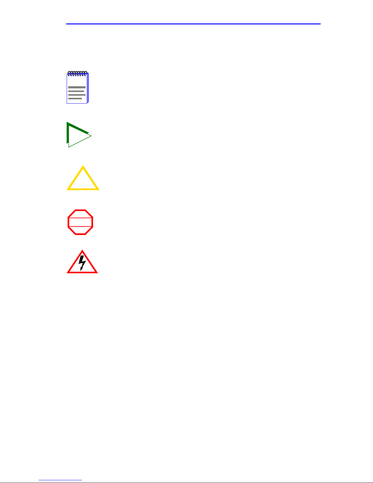
The following conventions are used throughout this document:
Note symbol. Calls the reader’s attention to any item of
NOTE
TIP
!
CAUTION
information that may be of special importance.
Tip symbol. Conveys helpful hints concerning procedures or
actions.
Caution symbol. Contains information essential to avoid
damage to the equipment.
Warning symbol. Warns against an action that could result in
WARNING
personal injury or death.
Electrical Hazard Warning symbol. Warns against an action
that could result in personal injury or death due to an electrical
hazard.
In Local Management sections, Bold type indicates fields, field values,
and commands that can be highlighted or selected by the user.
In Local Management sections, keystrokes are shown in UPPERCASE.
Italic type denotes complete book titles.
2H22-08R SmartSwitch 2208 User’s Guide Page 1-9

Chapter 1: Introduction
1.7 GETTING HELP
For additional support related to this device or document, contact the
Cabletron Systems Global Call Center:
World Wide Web http://www .cabletron.com/
Phone (603) 332-9400
Internet mail support@cabletron.com
FTP ftp://ftp.cabletron.com/
Login
Password
To send comments or suggestions concerning this document, contact the
Cabletron Systems Technical Writing Department via the following
email address: TechWriting@cabletron.com
Make sure to include the document Part Number in the email message.
anonymous
your email address
Before calling the Cabletron Systems Global Call Center, have the
following information ready:
• Your Cabletron Systems service contract number
• A description of the failure
• A description of any action(s) already taken to resolve the problem
(e.g., changing mode switches, rebooting the unit, etc.)
• The serial and revision numbers of all involved Cabletron Systems
products in the network
• A description of your network environment (layout, cable type, etc.)
• Network load and frame size at the time of trouble (if known)
• The device history (i.e., have you returned the device before, is this a
recurring problem, etc.)
• Any previous Return Material Authorization (RMA) numbers
Page 1-10 2H22-08R SmartSwitch 2208 User’s Guide

Related Manuals
1.8 RELATED MANUALS
The following manuals may help the user to set up and manage the
2H22-08R:
Cabletron Systems HSIM-A6DP User’s Guide
Cabletron Systems HSIM-F6 User’s Guide
Cabletron Systems HSIM-FE6 User’s Guide
Cabletron Systems HSIM-W6 Installation Guide
Cabletron Systems HSIM-W84 Installation Guide
Cabletron Systems HSIM-W87 User’s Guide
Cabletron Systems HSIM-G01/G09 User’s Guide
Cabletron Systems Ethernet Technology Guide
Cabletron Systems Cabling Guide
Cabletron Systems Port Based VLAN User’s Guide
Cabletron Systems SmartTrunk User’s Guide
These manuals can be obtained from the World Wide Web in Adobe
Acrobat Portable Document Format (PDF) at the following site:
http://www.cabletron.com/
All documentation for the Cabletron Systems SecureF ast VLAN
NOTE
Manager software is contained on the VLAN Manager
CD-ROM. The documentation f or the HSIM-W6 and HSIM-W84
is on the QuickSET CD-ROM.
2H22-08R SmartSwitch 2208 User’s Guide Page 1-11

Chapter 1: Introduction
Page 1-12 2H22-08R SmartSwitch 2208 User’s Guide

CHAPTER 2
NETWORK REQUIREMENTS
Before installing the 2H22-08R or Fast Ethernet Interface Module(s)
(FE-100TX, FE-100FX, or FE-100F3) in your network, review the
requirements and specifications referred to in this chapter to ensure
satisfactory equipment performance. Failure to follow these guidelines
may produce poor network performance.
The Cabletron Systems Cabling Guide and SmartTrunk User’s
NOTE
2.1 SmartTrunk
Guide, referred to in the following sections, are found on the
Cabletron Systems World Wide Web site:
http://www.cabletron.com/
To connect the 2H22-08R to a network so it can take advantage of the
SmartTrunk feature, there are certain rules concerning port connections
and configurations that must be followed for proper operation. Refer to
the Cabletron Systems SmartTrunk User’s Guide for additional
information.
2.2 10BASE-T NETWORK
When connecting a 10BASE-T segment to any of the 2H22-08R ports
(Interfaces 1 through 8), ensure that the network meets the Ethernet
network requirements of the IEEE 802.3 standard for 10BASE-T. Refer to
the Cabletron Systems Cabling Guide for details.
2H22-08R SmartSwitch 2208 User’s Guide Page 2-1

Chapter 2: Network Requirements
2.3 100BASE-TX NETWORK
The 2H22-08R, with an FE-100TX installed in ports 7 and 8, provides an
RJ45 connection that supports UTP cabling with an impedance between
85 and 111 ohms. The device at the other end of the twisted pair segment
must meet IEEE 802.3u 100BASE-TX Fast Ethernet network
requirements for the devices to operate at 100 Mbps. Refer to the
Cabletron Systems Cabling Guide for details.
The 2H22-08R with an FE-100TX installed is capable of
NOTE
operating at either 10 or 100 Mbps. The FE-100TX can
automatically sense the speed of the other device and adjusts
its speed accordingly.
2.4 100BASE-FX FIBER OPTIC NETWORK
Ports 7 and 8 of the 2H22-08R support the Cabletron Systems FE-100FX
and FE-100F3 fiber optic interface modules. The device at the other end
of the fiber optic segment must meet the 100BASE-FX Fast Ethernet
network requirements to operate at 100 Mbps. Refer to the Cabletron
Systems Cabling Guide for details.
Multimode Fiber Optic Cable Length
The maximum multimode fiber optic cable length of a 100BASE-FX
segment is covered in the Cabletron Systems Cabling Guide.
Single Mode Fiber Cable Lengths
The maximum single mode fiber optic length of a 100BASE-FX se gment
may be no more than 5 km between Data Terminal Equipment (DTE to
DTE) in half duplex mode or 20 km (DTE to DTE) in full duplex mode.
Single Mode Cable Loss
T est the single mode fiber optic cable with a fiber optic attenuation test set
adjusted for a 1300 nm wavelength. This test verifies that the signal loss is
within an acceptable level. The maximum loss for a single mode cable is
10.0 dB.
Page 2-2 2H22-08R SmartSwitch 2208 User’s Guide

CHAPTER 3
INSTALLATION
Only qualified personnel should install the 2H22-08R.
This chapter provides the instructions required to install the 2H22-08R.
Follow the order of the sections listed below to correctly install the
2H22-08R.
• Required Tools (Section 3.1)
• Unpacking the 2H22-08R (Section 3.2)
• Installing Options (Section 3.3)
• Installing the 2H22-08R (on a shelf or tabletop, or into a standard rack)
(Section 3.4)
• Connecting to the Network (Section 3.6)
• Completing the Installation (Section 3.7)
3.1 REQUIRED T OOLS
A Phillips screwdriver is required to install the 2H22-08R in a rack.
2H22-08R SmartSwitch 2208 User’s Guide Page 3-1

Chapter 3: Installation
3.2 UNPACKING THE 2H22-08R
T o unpack the 2H22-08R and verify the contents of the shipment, proceed
as follows:
1. Open the carton and remove the packing material protecting the
2H22-08R.
2. Verify the contents of the carton as listed in Table 3-1.
Table 3-1 Contents of 2H22-08R Carton
Item Quantity
2H22-08R 1
Antistatic Wrist Strap 1
Console Cable Kit 1
Rackmount Kit 1
Strain-Relief Bracket 1
Power Cord 2
3. Remove the black and yellow tape seal on the non-conductive bag to
remove the 2H22-08R.
4. Perform a visual inspection of the device for any signs of physical
damage. If there are any items missing or damaged, contact Cabletron
Systems Global Call Center as described in Section 1.7.
3.3 INSTALLING OPTIONS
Install any optional equipment before proceeding to
NOTE
Section 3.4.
If the 2H22-08R is to be installed with an optional Fast Ethernet Interface
Module, refer to Appendix C for installation instructions.
Page 3-2 2H22-08R SmartSwitch 2208 User’s Guide
Installing the 2H22-08R
3.4 INSTALLING THE 2H22-08R
The 2H22-08R may be installed on a tabletop, shelf, or in a 19-inch rack.
Section 3.4.1 provides the rules and instructions for a tabletop and shelf
installations, and Section 3.4.2 provides the rules and instructions for a
rackmount installation.
To ensure proper ventilation and prevent overheating, leave a
!
CAUTION
minimum clearance space of 5.1 cm (2.0 in) at the left, right,
and rear of the 2H22-08R.
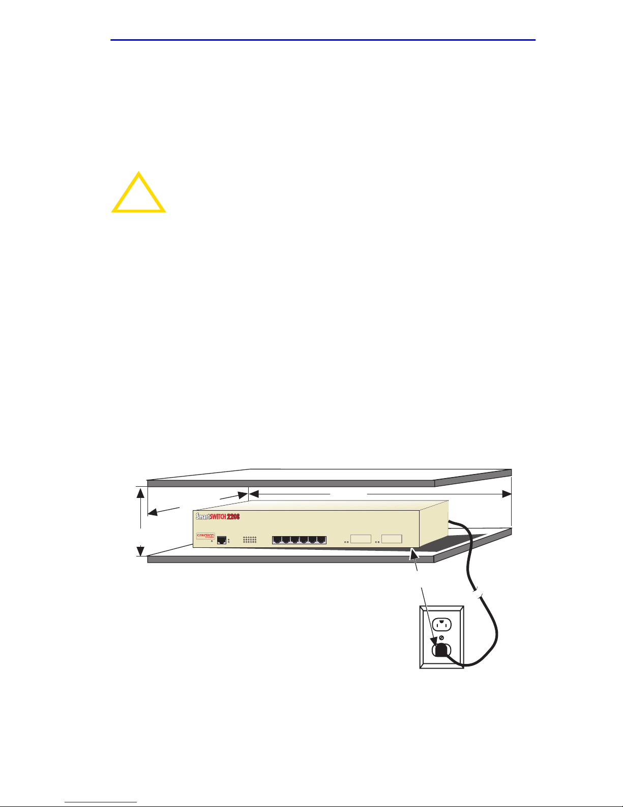
3.4.1 Tabletop and Shelf Installations
Tabletop and shelf installations must be within reach of the network
cabling and meet the requirements listed below:
• Locate the 2H22-08R within seven feet of an appropriately grounded
power source and an unrestricted surface area as shown in Figure 3-1
that meets the power supply requirements listed in Appendix A.
• In a shelf installation, the shelf must support 13.6 kg (30 lb) of static
weight for each 2H22-08R.
• Maintain a temperature of between 5°C (41°F) and 40°C (104°F) at
the installation site with fluctuations of less than 10°C (18°F) per hour .
B
A
2H22-08R
RESET
A = 15 cm (6 in)
B = 45 cm (22.5 in)
C = 53 cm (21 in)
D = 213 cm (7 ft)
PWR
CPU
216543
COM
1X 5X 6X4X3X2X
C
7
8
D
2251-06
Figure 3-1 Tabletop or Shelf Installation
2H22-08R SmartSwitch 2208 User’s Guide Page 3-3

Chapter 3: Installation
3.4.2 Rackmount Installation
Rackmount installations must be within reach of the network cabling and
meet the requirements listed below:
• Locate the 2H22-08R within seven feet of an appropriately grounded
power source and an unrestricted surface area as shown in Figure 3-1
that meets the power supply requirements listed in Appendix A.
• Maintain a temperature of between 5°C (41°F) and 40°C (104°F) at
the installation site with fluctuations of less than 10°C (18°F) per hour .
The 2H22-08R is shipped with a strain-relief bracket for cable
management. The rackmount kit contains the rackmount brackets and
mounting screws for installing it in a 19-inch rack.
Before installing the 2H22-08R into a rack, ensure that the rac k
WARNING
supports the device(s) without compromising the stability of the
rack. Otherwise, personal injury and/or equipment damage
may result.
Attaching the Strain-Relief Bracket
Use of the strain-relief bracket is optional, but recommended to reduce
cable damage and maintain an orderly environment. Attach the
strain-relief bracket to the front of the 2H22-08R as follows:
1. Locate the strain-relief bracket and four 8-32 x 3/8-inch pan-head
screws in the rackmount kit.
Do not attempt to attach the strain-relief bracket with screws
!
CAUTION
other than the 8-32 x 3/8-inch screws included with the
2H22-08R. Use of longer screws may damage the unit.
2. Attach the strain-relief bracket to the bottom of the 2H22-08R using
the four 8-32 x 3/8-inch pan-head screws (Figure 3-2).
Page 3-4 2H22-08R SmartSwitch 2208 User’s Guide
 Loading...