

Page 1
SmartSwitch 2200 DC POWER SUPPLY INSTRUCTION SHEET
This document provides additional information to the SmartSwitch 2200 user’s guide shipped with your device. This
document describes how to connect the dc version of a SmartSwitch 2200 device to 48 or 60 Vdc (48/60 Vdc) power
sources. Except for special grounding considerations for a particular type of rack installation and the two dc power
supplies, the device is installed and functions the same as the ac version. The two dc power supplies in the device have
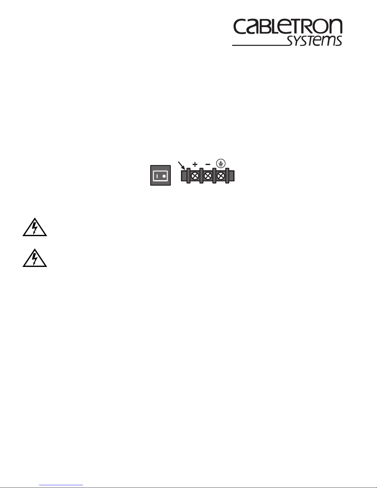
their own on/off switch and input power strip, and are each rated at 125 watts. The on/off power switches and input
power strips are similar to the ones shown in Figure 1.
DC Input Power Strip
ON/OFF
Figure 1 DC Power Supply ON/OFF Switch and DC Input Power Strip
ONLY QUALIFIED PERSONNEL SHOULD PERFORM THESE INSTALLATION PROCEDURES.
TO REDUCE THE RISK OF ELECTRIC SHOCK OR ENERGY HAZARDS:
• CONNECT TO A RELIABLY GROUNDED 48/60 VDC SELV SOURCE.
• ENSURE THE BRANCH CIRCUIT OVERCURRENT PROTECTION IS RATED AT A MINIMUM
OF 15 A.
• USE 12 or 14 AWG SOLID COPPER CONDUCTORS ONLY.
• ENSURE THAT A READIL Y A CCESSIBLE DISCONNECT DEVICE THA T IS SUITABL Y APPR OVED
AND RATED, IS INCORPORATED IN THE FIELD WIRING.
TO BE INSTALLED IN A RESTRICTED ACCESS AREA IN ACCORDANCE WITH THE NEC OR THE
AUTHORITY HAVING JURISDICTION.
2272-01
DC POWER SUPPLY REQUIREMENT
Input power can be 48 or 60 Vdc with a maximum current drain of 4.9 A for each power supply.
INSTALLATION REQUIREMENT
Each dc power supply input requires either a 48 Vdc or 60 Vdc power source supplied by three 18 AWG (American
Wire Gauge) copper wires. These wires must be terminated with either ring or spade terminals that accept a #6 screw.
P/N 9032790-01 Page 1 of 4
Page 2
BONDING THE DC DEVICE
If the device is going to be mounted in a rack and needs to meet the GR-1089-CORE Section 9 bonding requirements,
use the following instructions to install the device into a 19-inch rack.
1. Attach the strain-relief bracket as described in the user’s guide.
2. If the SmartSwitch 2200 device uses the side mounting brackets, proceed to step 3. If the device uses the bottom
mounting brackets, proceed to step 4.
3. To install a device with side mounting brackets, proceed as follows:
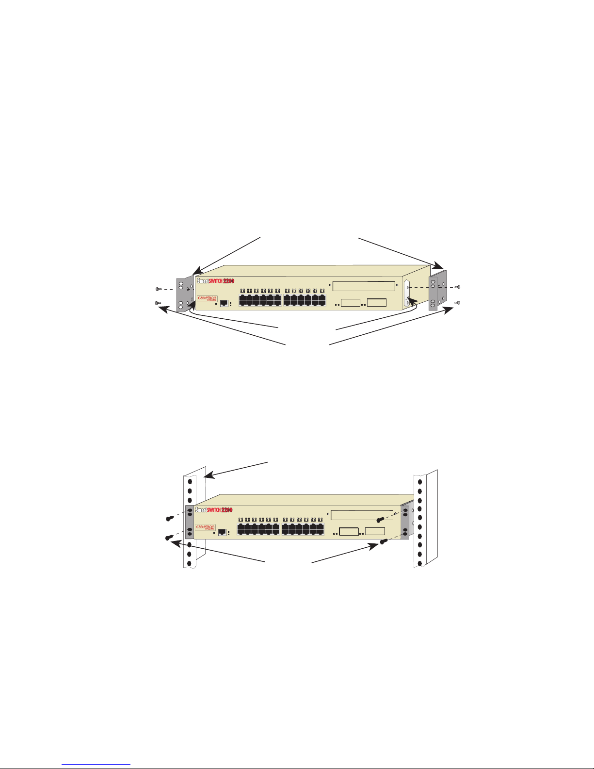
a. Remove and discard the four cover screws (two from each side) located along the front edges of each side of the
device.
b. Remove the paint from around the area near the mounting holes on the left and right side of the cover of the
device. See Figure 2.
c. Apply a thin layer of anti-oxidant to the surface where the paint was removed.
Rackmount Brackets (2)
2E42-27RDC
2
1
34567811
PWR
RESET
CPU
1X 3X 5X 7X 9X 11X 13X 15X 17X 19X 21X 23X
COM
16
121314
10
9
20
22
24
15
171819
21
23
2625
Remove Paint
Screws (4)
2272-04
Figure 2 Installing the Rackmount Brackets
d. Locate the four 6-32 x 3/8-inch flathead screws in the rackmount kit. Use these screws to attach the rackmount
brackets to the sides of the device as shown in Figure 2.
e. With the mounting brackets installed, position the device between the vertical frame members of the 19-inch
rack and fasten it securely with thread-forming mounting screws (user supplied) as shown in Figure 3.
19-Inch Rack
2E42-27RDC
2
1
34567811
PWR
RESET
CPU
1X 3X 5X 7X 9X 11X 13X 15X 17X 19X 21X 23X
COM
16
121314
10
15
9
Screws (4)
171819
20
22
24
21
23
2625
f. Proceed to the section, Connecting a Device to a 48/60 Vdc Power Source .
P/N 9032790-01 Page 2 of 4
1960-03
Figure 3 Installing the Device in a Rack
Page 3
4. To install a device with bottom mounting brackets, proceed as follows:
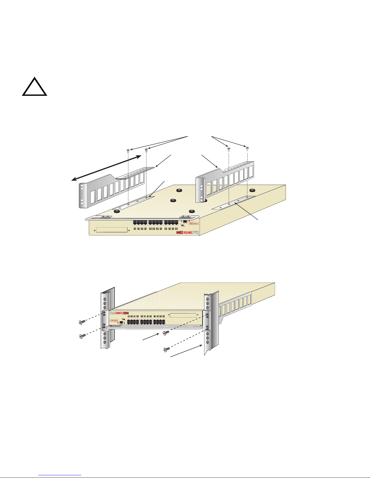
a. Apply a thin layer of anti-oxidant to the paint-free areas where the brackets will be mounted. See Figure 4.
b. There are several mounting holes in the rackmount brackets and the bottom of the chassis so that each mounting
bracket may be adjusted forward or backward to mount the device further into, or out of the rack, depending on
the installation requirements. Position the rackmount brackets over the appropriate holes.
c. Locate the four 6-32 x 1/4-inch flathead screws in the rackmount kit.
Do not use screws longer than 1/4 inch. Screws longer than 1/4 inch will damage the electronics in the
device.
!
CAUTION
d. Attach the rackmount brackets to the bottom of the device using the four 6-32 x 1/4-inch flathead screws, as
shown in Figure 4.
Screws
Rackmount Brackets
Paint-Free Area
COM
2H252-25R
CPU
TELCO
CONSOLE
17
11
19
13
23
21
18
20
16
24
22
567891015
14
12
RESET
PWR
DPX-SPD
2X 4X 6X 8X 10X 12X 14X 16X 18X 20X 22X 24X
RX-TX
MODE
3
1
LED
4
2
FAST ETHERNET WORKGROUP SWITCH
Paint-Free Area
25041-04
Figure 4 Installing the Rackmount Brackets
e. With the mounting brackets installed, position the device between the vertical frame members of the 19-inch
rack and fasten it securely with thread-forming mounting screws (user supplied) as shown in Figure 5.
FAST ETHERNET WORKGROUP SWITCH
2
4
LED
1
567891015
3
MODE
RX-TX
2X 4X 6X 8X 10X 12X 14X 16X 18X 20X 22X 24X
DPX-SPD
PWR
RESET
CPU
2H252-25R
COM
Screws
19-Inch Rack
Figure 5 Installing the Device in a Rack
22
16
12
20
24
14
18
21
11
19
13
23
17
25041-05
f. Proceed to the next section, Connecting a Device to a 48/60 Vdc Power Source .
P/N 9032790-01 Page 3 of 4
Page 4
CONNECTING THE DEVICE TO A 48/60 VDC POWER SOURCE
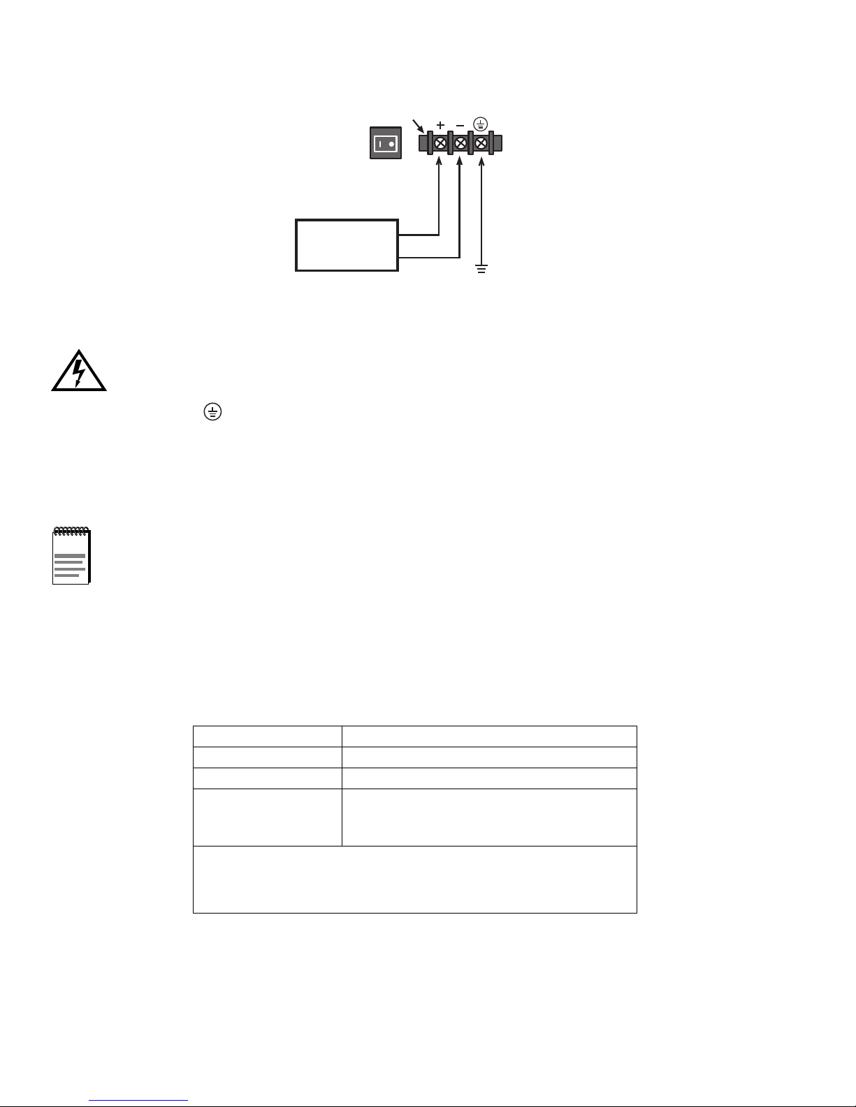
To connect the device to a 48/60 Vdc power source, face the rear of the device, then refer to Figure 6 and proceed as
follows:
DC Input Power Strip
ON/OFF
48 or 60 Vdc
Power Source
Figure 6 Connecting 48/60 Vdc Power Source to the Power Supply
+
-
Earth
Ground
2790-01
To prevent injury or damage to the equipment, remove power from the 48/60 Vdc power sources before
proceeding with the following steps and do not restore the 48/60 Vdc power until instructed to do so.
1. Connect the ground terminal of the dc input power strip to an appropriate earth ground.
2. Refer to Figure 6 for the proper connections to a 48/60 Vdc power source. Then connect the output leads of the
48/60 Vdc power source being used to the negative (-) and positive (+) terminals on the dc input power strip.
3. Repeat steps 1 and 2 to connect a 48/60 Vdc power source to the other dc input power strip on the device.
4. Restore power from the 48/60 Vdc power sources. If an alarm sounds, refer to the following note.
NOTE
If a dc power supply sounds an audible alarm, there is a polarity reversal. Turn off the 48/60 Vdc power
source to that power supply, then reverse the positive and negative leads to the dc input power strip of that
power supply. Restore power from the 48/60 Vdc power source. If the alarm sounds again, turn off the
48/60 Vdc power source and call for technical support. Refer to Getting Help for instructions.
5. Press the on/off power switch of each power switch to the on position.
6. Follow the instructions provided in your SmartSwitch 2200 user’s guide to install, power-up, and connect the device
to the network.
GETTING HELP
For additional support, contact Cabletron Systems using one of the following methods:
World Wide Web http://www.cab letron.com/
Phone (603) 332-9400
Internet mail [email protected]
FTP ftp://ftp.ctron.com/
Login
Password
To send comments or suggestions concerning this document, contact the
Cabletron Systems Technical Writing Department via the following
email address: [email protected]
Make sure to include the document Part Number in the email message.
1999 by Cabletron Systems, Inc., P.O. Box 5005, Rochester, NH 03866-5005
All Rights Reserved. Printed in the United States of America.
Order Number: 9032790-01 January 1999
Cabletron Systems is a registered trademark and SmartSwitch is a trademark of Cabletron Systems, Inc.
All other product names mentioned in this document may be trademarks or registered trademarks of their respective companies.
The information in this document is proprietary and is not to be copied in any form, or by any means, without the written consent of Cabletron Systems.
anonymous
your email address
P/N 9032790-01 Page 4 of 4
 Loading...