

Cabletron Systems SmartSTACK STS16-20RM, SmartSTACK STS16-20R, SmartSTACK STS16-20FRM Installation And User Manual
Page 1

SmartStack
STS16-20RM/STS16-20FRM
Token Ring Switches
Installation
and
User Guide
Page 2

Page 3

Notice
Cabletron Systems reserves the right to make changes in specifications and other
information contained in this document without prior notice. The reader should in all
cases consult Cabletron Systems to determine whether any such changes have been made.
The hardware, firmware, or software described in this manual is subject to change
without notice.
IN NO EVENT SHALL CABLETRON SYSTEMS BE LIABLE FOR ANY
INCIDENTAL, INDIRECT, SPECIAL, OR CONSEQUENTIAL DAMAGES
WHATSOEVER (INCLUDING BUT NOT LIMITED TO LOST PROFITS) ARISING
OUT OF OR RELATED TO THIS MANUAL OR THE INFORMATION CONTAINED
IN IT, EVEN IF CABLETRON SYSTEMS HAS BEEN ADVISED OF, KNOWN, OR
SHOULD HAVE KNOWN, THE POSSIBILITY OF SUCH DAMAGES.
i
© October 1999 by:
Cabletron Systems, Inc.
35 Industrial Way
Rochester, NH 03867
All Rights Reserved.
Order Number: 9032957-01
(OC-7052 v. 1.1, 710001810)
SmartStack
CompuServe
i960 microprocessor
Ethernet
is a trademark of Cabletron Systems, Inc.
is a registered trademark of CompuServe, Inc.
is a registered trademark of Intel Corp.
is a trademark of Xerox Corporation.
Notice
Page 4
ii
FCC Notice
This device complies with Part 15 of the FCC rules. Operation is subject to the following
two conditions: (1) this device may not cause harmful interference, and (2) this device
must accept any interference received, including interference that may cause undesired
operation.
NOTE:
digital device, pursuant to Part 15 of the FCC rules. These limits are designed to provide
reasonable protection against harmful interference when the equipment is operated in a
commercial environment. This equipment uses, generates, and can radiate radio
frequency energy and if not installed in accordance with the operator’s manual, may
cause harmful interference to radio communications. Operation of this equipment in a
residential area is likely to cause interference in which case the user will be required to
correct the interference at his own expense.
WARNING:
approved by the party responsible for compliance could void the user’s authority to
operate the equipment.
This equipment has been tested and found to comply with the limits for a Class A
Changes or modifications made to this device which are not expressly
VCCI Notice
This is a Class A product based on the standard of the Voluntary Control Council for
Interference by Information Technology Equipment (VCCI). If this equipment is used in
a domestic environment, radio disturbance may arise. When such trouble occurs, the user
may be required to take corrective actions.
Industry Canada Notice
This digital apparatus does not exceed the Class A limits for radio noise emissions from
digital apparatus set out in the Radio Interference Regulations of the Canadian
Department of Communications.
Le présent appareil numérique n'émet pas de bruits radioélectriques dépassant les limites
applicables aux appareils numériques de la class A prescrites dans le Règlement sur le
brouillage radioélectrique édicté par le ministère des Communications du Canada.
Notice
Page 5

Declarati on of Co nformity
Addendum
iii
Application of Council Directive(s):
Manufacturer’s Name:
Manufacturer’s Address:
European Representative Name:
European Representative Address:
Conformance to Directive(s)/Product Standards:
Equipment Type/Environment:
89/336/EEC
73/23/EEC
Cabletron Systems, Inc.
35 Industrial Way
PO Box 5005
Rochester, NH 03867
Mr. J. Solari
Cabletron Systems Limited
Nexus House,
Newbury Business Park
London Road, Newbury
Berkshire RG13 2PZ, England
EC Directive 89/336/EEC
EC Directive 73/23/EEC
EN 55022
EN 50082-1
EN 60950
Networking Equipment, for use
in a Commercial or Light
Industrial Environment.
We the undersigned, hereby declare, under our sole responsibility, that the equipment
packaged with this notice conforms to the above directives.
Manufacturer Legal Representative in Europe
Mr. Ronald Fotino
Full Name Full Name
Principal Compliance Engineer
Title Title
Rochester, NH, USA
Location Location
Mr. J. Solari
Managing Director - E.M.E.A.
Newbury, Berkshire, England
Notice
Page 6

iv
Table of Contents
1. Introduction 1
Switching Technology . . . . . . . . . . . . . . . . . . . . . . . 2
Switch of Switches. . . . . . . . . . . . . . . . . . . . . . . 2
Switch of Servers . . . . . . . . . . . . . . . . . . . . . . . 3
Switch of Hubs . . . . . . . . . . . . . . . . . . . . . . . . . 3
Switch of Desktops . . . . . . . . . . . . . . . . . . . . . . 3
Switch of Floors and Buildings. . . . . . . . . . . . . . . . . 4
Switch of Routers . . . . . . . . . . . . . . . . . . . . . . . 4
Front Panel Details . . . . . . . . . . . . . . . . . . . . . . . . 5
The MANAGEMENT Port . . . . . . . . . . . . . . . . . . . 5
Token Ring Ports . . . . . . . . . . . . . . . . . . . . . . . 6
Switched Port Analyzer . . . . . . . . . . . . . . . . . . . . 6
SmartStack Interface Modules. . . . . . . . . . . . . . . . . 7
Reset Button . . . . . . . . . . . . . . . . . . . . . . . . . . 7
System Request Button . . . . . . . . . . . . . . . . . . . . 7
Labels . . . . . . . . . . . . . . . . . . . . . . . . . . . . . 7
Status and Activity LEDs . . . . . . . . . . . . . . . . . . . 8
Back Panel Details. . . . . . . . . . . . . . . . . . . . . . . . . 10
Features and Specifications . . . . . . . . . . . . . . . . . . . . 11
Features . . . . . . . . . . . . . . . . . . . . . . . . . . . . 11
Specifications . . . . . . . . . . . . . . . . . . . . . . . . . 13
2. Switch Overview 17
Multiple Simultaneous Conversations . . . . . . . . . . . . . . . 18
Low Latency . . . . . . . . . . . . . . . . . . . . . . . . . . . . 19
Address Management . . . . . . . . . . . . . . . . . . . . . . . 19
Multiple Bridging Modes . . . . . . . . . . . . . . . . . . . . . . 20
Source Route Switching (SRS) . . . . . . . . . . . . . . . . 21
Source Route Bridging (SRB) . . . . . . . . . . . . . . . . . 21
Source Route Transparent (SRT) . . . . . . . . . . . . . . . 22
SRT/SRB . . . . . . . . . . . . . . . . . . . . . . . . . . . 22
Filtering . . . . . . . . . . . . . . . . . . . . . . . . . . . . . . 23
Congestion Control . . . . . . . . . . . . . . . . . . . . . . . . 23
Three Switching Modes . . . . . . . . . . . . . . . . . . . . . . 24
Cut-Through . . . . . . . . . . . . . . . . . . . . . . . . . . 24
Store and Forward . . . . . . . . . . . . . . . . . . . . . . . 24
Auto (Adaptive Cut-Through) . . . . . . . . . . . . . . . . . 24
Token Ring Port Operation Modes . . . . . . . . . . . . . . . . 25
RI/RO-Like Connection . . . . . . . . . . . . . . . . . . . . . . 26
Transmission Priority Queues . . . . . . . . . . . . . . . . . . . 27
Notice
Page 7

ClearSession Support . . . . . . . . . . . . . . . . . . . . . . 27
CrossLink Connections. . . . . . . . . . . . . . . . . . . . . . 28
Spanning Tree Protocol Support . . . . . . . . . . . . . . . . . 29
VLAN Support . . . . . . . . . . . . . . . . . . . . . . . . . . 29
Dynamic Source Route Recovery . . . . . . . . . . . . . . . . 31
Management . . . . . . . . . . . . . . . . . . . . . . . . . . . 34
SNMP . . . . . . . . . . . . . . . . . . . . . . . . . . . . 34
SmartStack Manager for Windows . . . . . . . . . . . . . . 35
Telnet Management and VT100 Management (Console) . . 35
IBM LAN Network Manager . . . . . . . . . . . . . . . . . 35
RMON Support . . . . . . . . . . . . . . . . . . . . . . . . . . 36
Built-in Port Counters. . . . . . . . . . . . . . . . . . . . . . . 37
Stackable Architecture . . . . . . . . . . . . . . . . . . . . . . 38
Back-to-Back . . . . . . . . . . . . . . . . . . . . . . . . . 38
Internal Stacker. . . . . . . . . . . . . . . . . . . . . . . . 38
External Stacker . . . . . . . . . . . . . . . . . . . . . . . 38
Optional Redundant Power Supply. . . . . . . . . . . . . . . . 39
v
3. Preparing for Installation 41
Safety Recommendations . . . . . . . . . . . . . . . . . . . . 41
Safety with Electricity. . . . . . . . . . . . . . . . . . . . . 41
Preventing Electrostatic Discharge Damage . . . . . . . . . 42
Site Requirements . . . . . . . . . . . . . . . . . . . . . . . . 43
Environment . . . . . . . . . . . . . . . . . . . . . . . . . 43
Chassis Accessibility . . . . . . . . . . . . . . . . . . . . . 43
Cooling and Airflow. . . . . . . . . . . . . . . . . . . . . . 43
Power. . . . . . . . . . . . . . . . . . . . . . . . . . . . . 43
Configuration Guidelines . . . . . . . . . . . . . . . . . . . . . 45
Frame Length Limit. . . . . . . . . . . . . . . . . . . . . . 45
IEEE 802.1D Spanning Tree . . . . . . . . . . . . . . . . . 46
Ring Numbers . . . . . . . . . . . . . . . . . . . . . . . . 47
Connecting to Other Non-IEEE 802.5j Compliant
Fiber Devices. . . . . . . . . . . . . . . . . . . . . . . . . 47
Sample Applications for the STS16-20RM and
the STS16-20FRM . . . . . . . . . . . . . . . . . . . . . . . . 48
Important Management Considerations . . . . . . . . . . . 52
4. Installation 53
Installation Summary . . . . . . . . . . . . . . . . . . . . . . . 53
Package Contents . . . . . . . . . . . . . . . . . . . . . . . . 54
Materials Needed for Installation . . . . . . . . . . . . . . . . . 55
Installing a SmartStack Interface Module . . . . . . . . . . . . 55
Mounting the Chassis . . . . . . . . . . . . . . . . . . . . . . 57
Notice
Page 8

vi
Rack or Cabinet Mounting . . . . . . . . . . . . . . . . . . . 57
Table-Mounting . . . . . . . . . . . . . . . . . . . . . . . . 58
Cabling. . . . . . . . . . . . . . . . . . . . . . . . . . . . . . . 59
Connecting Devices to the Token Ring Ports . . . . . . . . . 59
Connecting Devices to the Token Ring Ports
Using Building Wiring . . . . . . . . . . . . . . . . . . . . . 60
Checking the Installation. . . . . . . . . . . . . . . . . . . . . . 61
Applying Power . . . . . . . . . . . . . . . . . . . . . . . . . . 62
5. Accessing Switch Management 65
Overview . . . . . . . . . . . . . . . . . . . . . . . . . . . . . . 65
Connecting the Console . . . . . . . . . . . . . . . . . . . . . . 66
Communication Problems . . . . . . . . . . . . . . . . . . . 68
Diagnostic Screen . . . . . . . . . . . . . . . . . . . . . . . 69
6. Switch Configuration 71
General Guidelines . . . . . . . . . . . . . . . . . . . . . . . . 72
Navigating within the Menus. . . . . . . . . . . . . . . . . . 73
Main Menu . . . . . . . . . . . . . . . . . . . . . . . . . . . . . 74
Configuration Menu . . . . . . . . . . . . . . . . . . . . . . . . 75
Switch Configuration Screen. . . . . . . . . . . . . . . . . . . . 76
Stack Configuration Screen . . . . . . . . . . . . . . . . . . 79
Module Information Screen . . . . . . . . . . . . . . . . . . 80
VLAN Configuration . . . . . . . . . . . . . . . . . . . . . . . . 82
VLAN Configuration Menu . . . . . . . . . . . . . . . . . . . 83
VLAN Configuration Screen . . . . . . . . . . . . . . . . . . 84
VLAN Parameter Configuration for CRF Screen . . . . . . . 86
VLAN Parameter Configuration for BRF Screen . . . . . . . 88
VLAN Port Configuration Screen . . . . . . . . . . . . . . . 90
IP Configuration Screen . . . . . . . . . . . . . . . . . . . . . . 91
BootP Requests and Parameters . . . . . . . . . . . . . . . 93
SNMP Configuration Menu . . . . . . . . . . . . . . . . . . . . 94
Spanning Tree Protocol . . . . . . . . . . . . . . . . . . . . . . 94
IEEE 802.1D Spanning Tree Protocol (STP) . . . . . . . . . 95
Spanning Tree for BRF Screen . . . . . . . . . . . . . . . . 96
Spanning Tree for CRF Screen . . . . . . . . . . . . . . . . 99
Port Spanning Tree Parameters Screen. . . . . . . . . . . 102
Current Spanning Tree Information Screen . . . . . . . . . 103
Port Configuration Screen . . . . . . . . . . . . . . . . . . . . 104
Switched Port Analyzer Menu . . . . . . . . . . . . . . . . . . 109
CrossLink . . . . . . . . . . . . . . . . . . . . . . . . . . . . 109
CrossLink Menu . . . . . . . . . . . . . . . . . . . . . . . 111
CrossLink Configuration Screen . . . . . . . . . . . . . . . 112
Notice
Page 9

vii
Setting up a CrossLink . . . . . . . . . . . . . . . . . . . . 113
Current CrossLink Information Screen . . . . . . . . . . . . 114
Address Filtering . . . . . . . . . . . . . . . . . . . . . . . . . 115
Filters and Port Security Menu . . . . . . . . . . . . . . . . 116
Configure Filters Screen . . . . . . . . . . . . . . . . . . . 117
Configure Port Security Mode Screen . . . . . . . . . . . . 119
View Port Filters Screen . . . . . . . . . . . . . . . . . . . 120
Protocol Filters Menu. . . . . . . . . . . . . . . . . . . . . 121
Protocol Class Assignment Screen . . . . . . . . . . . . . 122
Port Filtering Attributes Screen. . . . . . . . . . . . . . . . 123
Address Aging . . . . . . . . . . . . . . . . . . . . . . . . . . 125
Address Aging Menu . . . . . . . . . . . . . . . . . . . . 126
Port Address Table Aging Screen . . . . . . . . . . . . . . 126
Master Address Table Aging Screen . . . . . . . . . . . . . 128
Password Menu . . . . . . . . . . . . . . . . . . . . . . . . . 129
Console/Telnet Sessions . . . . . . . . . . . . . . . . . . . . . 131
Console Configuration Menu . . . . . . . . . . . . . . . . . 131
Serial Link Configuration Screen . . . . . . . . . . . . . . . 132
Creating a Console Session Using a Modem . . . . . . . . 133
Stopping the Console Session . . . . . . . . . . . . . . . . 133
Telnet Configuration Screen . . . . . . . . . . . . . . . . . 134
Telnet Sessions Screen . . . . . . . . . . . . . . . . . . . 135
Starting the Telnet Session. . . . . . . . . . . . . . . . . . 136
Stopping the Telnet Session . . . . . . . . . . . . . . . . . 136
Involuntary Termination of the Telnet Session . . . . . . . . 136
Syslog Daemon Screen . . . . . . . . . . . . . . . . . . . . . 138
DSRR Configuration . . . . . . . . . . . . . . . . . . . . . . . 140
DSRR Group Configuration Screen . . . . . . . . . . . . . 142
DSRR Configuration Screen . . . . . . . . . . . . . . . . . 143
Download/Upload Menu . . . . . . . . . . . . . . . . . . . . . 146
Serial Link Download Screen. . . . . . . . . . . . . . . . . 147
TFTP . . . . . . . . . . . . . . . . . . . . . . . . . . . . . 148
TFTP Download/Upload Screen . . . . . . . . . . . . . . . 149
Reset Screen . . . . . . . . . . . . . . . . . . . . . . . . . . . 151
7. Monitoring the Network from the Console
Statistics Me nu 153
Statistics Menu . . . . . . . . . . . . . . . . . . . . . . . . . . 154
Switch Statistics Screen . . . . . . . . . . . . . . . . . . . . . 155
Power Supply Information Screen . . . . . . . . . . . . . . . . 157
Port Status Screen . . . . . . . . . . . . . . . . . . . . . . . . 158
Port Statistics Menu . . . . . . . . . . . . . . . . . . . . . . . 160
General Statistics Screen . . . . . . . . . . . . . . . . . . 161
Notice
Page 10

viii
802.5 Statistics Screen . . . . . . . . . . . . . . . . . . . 165
802.5 State Information Screen . . . . . . . . . . . . . . . 168
802.5 DTR MAC Information Menu . . . . . . . . . . . . . 170
TXI Information Screen . . . . . . . . . . . . . . . . . . . 171
Station-CPort Information Screen . . . . . . . . . . . . . . 173
Address Tables Menu . . . . . . . . . . . . . . . . . . . . . . 175
Master Address Table Screen . . . . . . . . . . . . . . . . 176
Master Route Descriptor Table Screen . . . . . . . . . . . 179
VLAN Address Table Screen . . . . . . . . . . . . . . . . 180
VLAN Route Descriptor Table Screen . . . . . . . . . . . . 181
Locate MAC Address Screen . . . . . . . . . . . . . . . . 182
Current Spanning Tree Information Screen . . . . . . . . . 183
Current Spanning Tree Information for a CRF Screen . . . 186
VLAN Statistics . . . . . . . . . . . . . . . . . . . . . . . . . 189
VLAN Statistics Screen for CRF . . . . . . . . . . . . . . . 189
VLAN Statistics Screen for BRF . . . . . . . . . . . . . . . 190
DSRR Status Screens . . . . . . . . . . . . . . . . . . . . . . 191
DSRR Status Tables Screen . . . . . . . . . . . . . . . . 191
DSRR Neighbor Table Screen. . . . . . . . . . . . . . . . 192
DSRR Acting as Backup Table Screen . . . . . . . . . . . 193
Diagnostic Test Results Screen . . . . . . . . . . . . . . . . . 194
Message Log Information Screen . . . . . . . . . . . . . . . . 195
Display Summary Screen . . . . . . . . . . . . . . . . . . . . 197
8. Monitoring the Network with SNMP 199
SNMP Setup . . . . . . . . . . . . . . . . . . . . . . . . . . . 199
IP Configuration Screen . . . . . . . . . . . . . . . . . . . . . 199
SNMP Configuration . . . . . . . . . . . . . . . . . . . . . . . 200
SNMP Configuration Screen. . . . . . . . . . . . . . . . . 200
Community Strings Screen . . . . . . . . . . . . . . . . . 201
Trap Receivers Screen . . . . . . . . . . . . . . . . . . . 203
List of Supported Traps from a Switch. . . . . . . . . . . . 204
9. Monitoring Port Traffic 209
Switched Port Analyzer Screen . . . . . . . . . . . . . . . . . 211
10. Troubleshooting 213
Obtaining Service . . . . . . . . . . . . . . . . . . . . . . 213
Troubleshooting in a Network . . . . . . . . . . . . . . . . 213
Start of Troubleshooting Process . . . . . . . . . . . . . . 213
Choosing a Troubleshooting Procedure . . . . . . . . . . . 214
Notice
Page 11

ix
11. Getting in Touch with Technical Support 219
Problem Report Form . . . . . . . . . . . . . . . . . . . . . . 220
Appendix A. Abbreviations 223
Appendix B. Cable and Pin Information 227
Connecting to the Out-of-Band Management Port . . . . . . 227
Out-of-Band Management Port and Cable Pin-Outs . . . . . 228
Twisted-Pair Cable Pin Outs . . . . . . . . . . . . . . . . . 230
Cabling Recommendations. . . . . . . . . . . . . . . . . . 231
Cable Length and Lobe Wiring Rules for
Dedicated-Media LAN Segments . . . . . . . . . . . . . . 233
Cable Length and Lobe Wiring Rules for
Shared-Media LAN Segments . . . . . . . . . . . . . . . . 235
Notice
Page 12

x
List of Figures
Figure 1. SmartStack STS16-20RM Token Ring Switch . . . . . . . 1
Figure 2. SmartStack STS16-20FRM Token Ring Switch . . . . . . 1
Figure 3. Location of LEDs, Switches, and Connectors
on STS16-20RM . . . . . . . . . . . . . . . . . . . . . . 5
Figure 4. Location of LEDs, Switches, and Connectors
on STS16-20FRM. . . . . . . . . . . . . . . . . . . . . . 5
Figure 5. The Back Panel . . . . . . . . . . . . . . . . . . . . . . . 10
Figure 6. Multiple Conversations Through a STS16-20RM or
STS16-20FRM Switch . . . . . . . . . . . . . . . . . . . 18
Figure 7. Typical Configuration with Switches
Using Multiple Bridging Modes . . . . . . . . . . . . . . . 20
Figure 8. A Switch Configured with Two VLANs . . . . . . . . . . . 30
Figure 9. Example of Dynamic Source Route Recovery, Base
Configuration . . . . . . . . . . . . . . . . . . . . . . . . 31
Figure 10. Example of Dynamic Source Route Recovery,
Normal State . . . . . . . . . . . . . . . . . . . . . . . . 32
Figure 11. Example of Dynamic Source Route Recovery,
Switch 1 Failed . . . . . . . . . . . . . . . . . . . . . . . 33
Figure 12. Typical LAN Segmentation . . . . . . . . . . . . . . . . . 48
Figure 13. A Simple Application of the Switch . . . . . . . . . . . . . 49
Figure 14. Typical Network without the SmartStack Switches . . . . . 50
Figure 15. Relieving the Overstressed Backbone . . . . . . . . . . . 50
Figure 16. Replacing SRBs with STS16-20RM or STS16-20FRM . . . 51
Figure 17. Star-Wired Topology of Interconnected Switches. . . . . . 52
Figure 18. Removing the SSIM Slot Cover . . . . . . . . . . . . . . . 56
Figure 19. Exposing the Rack Mounting Bracket. . . . . . . . . . . . 57
Figure 20. Mounting the Switch in a Rack or Cabinet . . . . . . . . . 58
Figure 21. Connecting Devices to Token Ring Ports . . . . . . . . . . 60
Figure 22. Connecting using Building Wiring . . . . . . . . . . . . . . 61
Figure 23. The Back Panel of the Switch. . . . . . . . . . . . . . . . 62
Figure 24. View of Console Connection—the MANAGEMENT port . . 66
Figure 25. Switch with Four VLANs . . . . . . . . . . . . . . . . . . 82
Figure 26. Setting up CrossLinks . . . . . . . . . . . . . . . . . . . 109
Figure 27. Primary and Traced DSRR Port . . . . . . . . . . . . . 141
Figure 28. TIA/EIA 232 Null-Modem Cable for the 25-pin Connector 229
Figure 29. TIA/EIA 232 Null-Modem Cable for the 9-pin Connector . 229
Figure 30. Straight-Through Cable . . . . . . . . . . . . . . . . . . 230
Figure 31. Data Connector-to-RJ-45 Straight-Through Cable . . . . 230
Notice
Page 13

List of Tables
Table 1. Status LEDs and Their Meanings . . . . . . . . . . . . . . 8
Table 2. Stack-link LEDs and Their Meanings . . . . . . . . . . . . 9
Table 3. Port LEDs and Their Meanings . . . . . . . . . . . . . . . 9
Table 4. Back Panel Switches and Connectors. . . . . . . . . . . 10
Table 5. Capacity Specifications . . . . . . . . . . . . . . . . . . 13
Table 6. Performance Specifications . . . . . . . . . . . . . . . . 14
Table 7. Specifications of Physical Characteristics . . . . . . . . . 14
Table 8. Supported MIBs . . . . . . . . . . . . . . . . . . . . . . 34
Table 9. Supported RMON Groups . . . . . . . . . . . . . . . . . 36
Table 10. Console Configuration Settings . . . . . . . . . . . . . . 67
Table 11. Modem Settings . . . . . . . . . . . . . . . . . . . . . . 133
Table 12. Symptom, LED State and Recommended Procedure . . . 214
Table 13. Connecting to the Management Port . . . . . . . . . . . 227
Table 14. Pin-out of the Management Port. . . . . . . . . . . . . . 228
Table 15. Copper Cable Types. . . . . . . . . . . . . . . . . . . . 231
Table 16. Multimode Optical Fiber Cable Types . . . . . . . . . . . 231
Table 17. Lobe Length for 150 Ohm Shielded Media . . . . . . . . 233
Table 18. Lobe Lengths for 100 Ohm Shielded or Unshielded Cable 233
Table 19. Lobe Lengths for 100 or 120 Ohm
Shielded or Unshielded Cable . . . . . . . . . . . . . . . 234
Table 20. Lobe Lengths for Recommended Fiber Cable. . . . . . . 234
Table 21. Alternate Optical Fibers . . . . . . . . . . . . . . . . . . 234
xi
Notice
Page 14

xii
Notice
Page 15
1. Introduction
This chapter discusses switching technology and how the SmartStack STS1620RM and/or the STS16-20FRM Token Ring Switch can be used to improve
network performance. This chapter also includes a list of features and
specifications for the switch.
1
➽ Note:
STS16-20FRM.
The topics of this chapter are presented under the following titles:
•
•
•
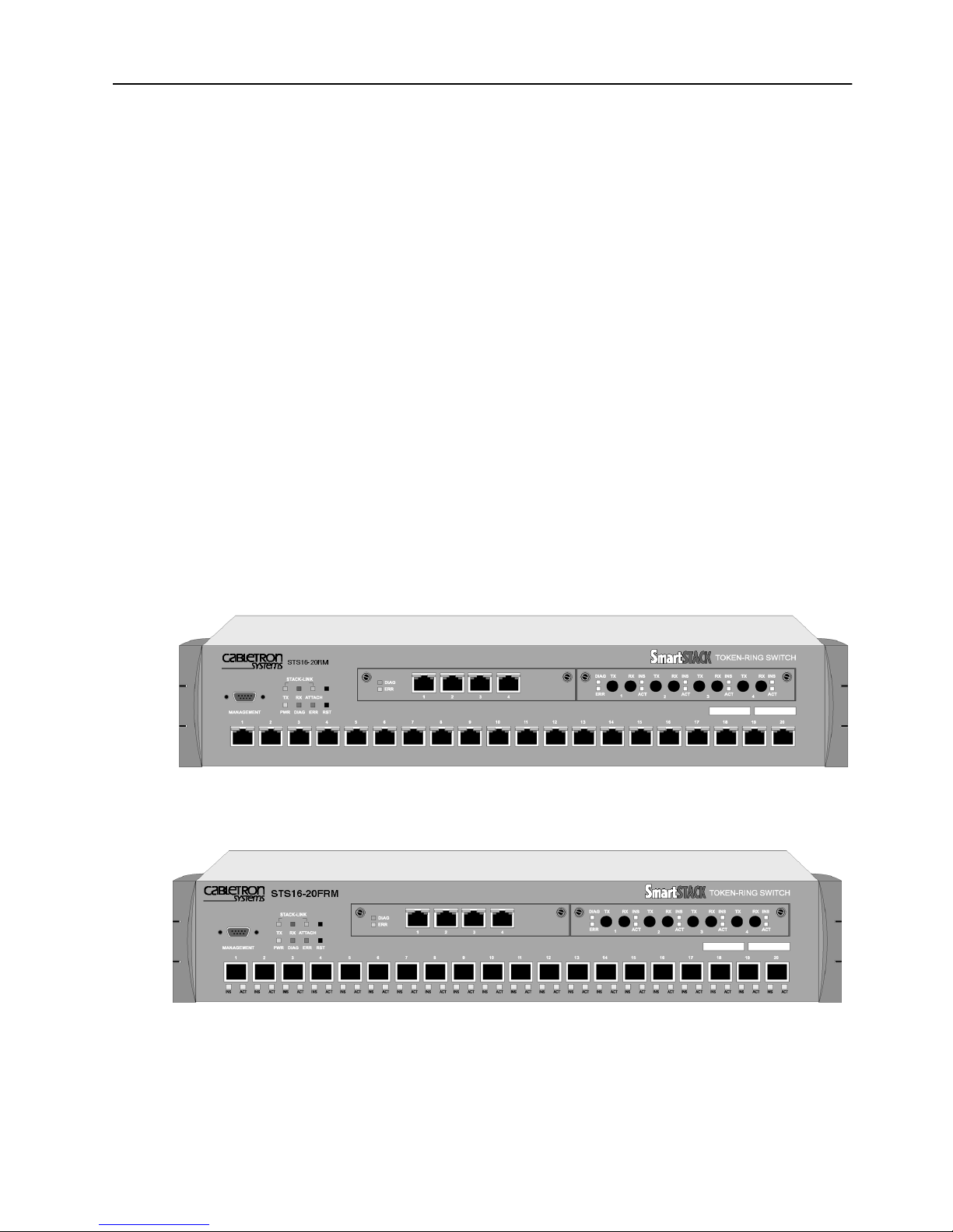
The folloiwing figures display a front view of the STS16-20RM and the STS1620FRM Token Ring switches.
References to SmartStack STS16-20RM are also applicable to SmartStack
“Switching Technology”, starting on page 2.
“Front Panel Details” starting on page 5 and “Back Panel Details” starting on
page 10.
“Back Panel Details”, starting on page 10.
Figure 1. SmartStack STS16-20RM Token Ring Switch
Figure 2. Smar tStack STS16-20FRM Token Ring Switch
Introduction SmartStack STS16-20RM/STS16-20FRM Token Ring Switches, P/N: 9032957-01
Page 16

2
Switching Technology
Demand for network bandwidth continues to grow, driven by the increasing
number of systems used in network-intensive applications. LAN segmentation has
been the prevalent method for addressing these demands and has been further
popularized by trends toward server centralization. However, the implementation
costs of LAN segmentation, as well as the real performance characteristics of
conventional network components, have served to limit growth of some Token
Ring networks. Alternative technologies for addressing bandwidth demands
present yet other inhibitors, usually relating to costs. Token Ring switching
provides users with an easy, cost-effective technique for addressing these demands.
Token Ring switches, such as the STS16-20RM and the STS16-20FRM, increase
throughput between Token Ring segments by supporting simultaneous, parallel
conversations. Switched connections between Token Ring segments last only for
the duration of the packet—new connections can be made between different
segments for the next packet.
Token Ring switches solve congestion problems caused by high-bandwidth devices
and powerful applications as well as the number of users. Therefore, each of these
devices—servers, for example—can be assigned its own 16 Mbps segment.
In Token Ring networks, the major bottleneck is typically the throughput to highbandwidth devices such as servers, and between routers, bridges, and switches. An
effective solution is full-duplex communication, an option for each segment
connected to a STS16-20RM or a STS16-20FRM port. Normally, Token Ring
operates in half-duplex communication mode, which means stations can either
receive or transmit. With full-duplex technology, two communicating stations can
transmit and receive at the same time. When packets can flow in both directions
simultaneously, effective Token Ring bandwidth doubles from 16 Mbps to 32 Mbps.
The STS16-20RM and the STS16-20FRM can forward Token Ring frames among
multiple, shared or dedicated Token Ring LAN segments. Using a frame
forwarding technique similar to that of a multiport Token Ring transparent bridge,
the switch uses Token Ring MAC addresses to forward Token Ring frames from
any of its ports to any other.
Switch of Switches
The STS16-20RM and the STS16-20FRM can be deployed in a variety of network
configurations, all of which provide a significant increase in network performance.
The series of Cabletron Token Ring products allows users to build network systems
that can transport data efficiently and scale upwards as throughput requirements
increase. The switches deliver high-reliability and media flexibility. These features
combine to allow the switches to be used as a switch of switches which provides
media flexibility in an Token Ring configuration.
SmartStack STS16-20RM/STS16-20FRM Token Ring Switches, P/N: 9032957-01 Introduction
Page 17

The STS16-20RM and the STS16-20FRM can easily connect with other
SmartStack products to deliver a broad range of network carrying capacity.
Bandwidth is easily scaled to meet all performance requirements.
Switch of Servers
With client/server applications, many client workstations may attempt to access a
single server at the same time. This traffic pattern may create bottlenecks at the
server. To further enhance performance, the STS16-20RM and the STS16-20FRM
can deliver dedicated bandwidth to high-speed file servers. All servers perform
better with dedicated 16 Mbps bandwidth.
Even better performance can be achieved by installing multiple adapters in the
server. By connecting these adapters to the switch, multiple 16 Mbps paths to the
server are created, a solution that is only possible when using a switch.
The switch ties together all Token Ring devices lined to a local wiring center. In
networks, where a significant portion of the traffic moves locally between client
and server, the switch can be very effective.
3
Switch of Hubs
When network traffic increases beyond the capability of hubs, contention results.
Applications suffer and may even fail. The net effect of such a network
configuration is that all devices share a single 16 Mbps data path, thus reducing
overall network efficiency. The STS16-20RM and STS16-20FRM can be very
effective when used as a switch of hubs.
The switches can alleviate contention through microsegmentation, or reducing the
number of devices in each shared segment. To provide microsegmentation, the
switches divides a single 16 Mbps segment into multiple 16 Mbps segments. As an
example, a workgroup has 16 Mbps of capacity. The 20 ports on the switches
support 10 simultaneous conversations with 20 hubs, thus providing the workgroup
with 160 Mbps bandwidth throughput, which results in a significant gain in
bandwidth.
Switch of Desktops
The STS16-20RM and the STS16-20FRM are a cost-effective means of providing
dedicated bandwidth to individual desktop workstations. In this application, the
switch replaces a hub, providing excellent, hub-like network management
statistics. Total network capacity and throughput increase dramatically for attached
desktop workstations.
Introduction SmartStack STS16-20RM/STS16-20FRM Token Ring Switches, P/N: 9032957-01
Page 18

4
Switch of Floors and Buildings
For network managers, multistory buildings and campuses can represent a unique
networking challenge. How can a network manager provide an efficient LAN
interconnect for users that are located on several floors of a building or in different
buildings?
Token Ring switching and the SmartStack product family can provide the best
solution. The STS16-20RM and the STS16-20FRM provide enhanced throughput
to local wiring closets that can be connected to a switch located in the data center.
Many networks consist of users located in different buildings of a campus
environment. The switches can be used as a collapsed backbone interconnecting
multiple buildings of a campus. They can provide the connectivity solution and
enhanced throughput that such campus environments require.
Switch of Routers
Router technology has had a significant impact on the design of today’s
internetworks. Routers have become the cornerstone of most production networks.
Although well equipped to provide firewall, WAN connectivity, security, and
connection between dissimilar LANs, routers are unable to provide high throughput
between desktop devices and servers. Because of these limitations, routers and
switches perform complimentary functions in the network.
The STS16-20RM and the STS16-20FRM can be used as a front-end to routers to
increase performance in each subnet. Communication between local clients and
servers is enhanced at the workgroup level below the router.
The switches can also be used to back-end routers. In networks were many routers
are interconnected over Token Ring and backbone performance is not acceptable,
the switches provide nonblocking communication between the routers for
enhanced network performance. This provides protocol transparency with
enhanced throughput in each subnet between local servers and desktops, thus
allowing network managers to build logical networks as large as network layer
protocol and broadcast traffic allow.
The Switched Port Analyzer also gives a collapsed backbone network superior
network management and the ability to perform protocol analysis from a single
location. The Switch Port Analyzer provides the latest technology for monitoring
switch-based networks and helps to reduce the cost of managing these networks.
SmartStack STS16-20RM/STS16-20FRM Token Ring Switches, P/N: 9032957-01 Introduction
Page 19
Front Panel Details
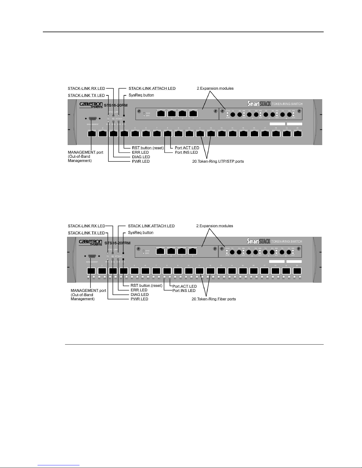
The front panel details of the switches are illustrated in Figure 3 and Figure 4. This
section lists all the connectors, controls, and LEDs of the front panel.
Figure 3. Location of LEDs, Switches, and Connectors
on STS16-20RM
5
Figure 4. Location of LEDs, Switches, and Connectors
on STS16-20FRM
The MANAGEMENT Po rt
The 9-pin, male, Out-of-Band Management (OBM) port labelled MANAGEMENT
functions as a DTE port.
This port enables attachment of a terminal, either local or remote, through a modem
connection. The terminal can be used to configure and monitor the switch.
The MANAGEMENT port automatically detects the baud rate of the terminal to
which it is attached.
Introduction SmartStack STS16-20RM/STS16-20FRM Token Ring Switches, P/N: 9032957-01
Page 20

6
Token Ring Ports
STS16-20RM
•
Twenty shielded RJ-45 connectors for Token Ring connection.
— Support for the IBM Cabling System via 150 ohm, shielded twisted-pair
(150 ohm STP); or 100 or 120 ohm unshielded twisted-pair via Category
3, 4, or 5 cables.
— These ports allow half-duplex (HDX) or full-duplex (FDX) connections to
other switches, hubs, or end nodes.
— Ports 19 and 20 can attac to a MAU/CAU RI/RO port
STS16-20FRM
•
Twenty fiber VF-45 connectors for Token Ring connection.
— These ports allow half-duplex (HDX) or full-duplex (FDX) connections to
other switches, hubs, or end nodes.
— All 20 fiber ports can attach to a MAU/CAU RI/RO port.
— On STS16-20FRM, UTP/STP connections are only available by installing
an SSIM-T5-04 Token-Ring SmartStack Interface Module.
The switch will automatically sense what type of Token Ring connection is
•
being employed on each of its ports, whether it is a connection:
— to a shared-media segment via a Token Ring concentrator (Station mode)
— to another Token Ring switch
— operating at 4 Mbps or at 16 Mbps
— to a dedicated-media segment, directly to a Token Ring LAN station
operating in half-duplex or full-duplex mode (Port mode)
The switch will automatically configure (requiring no operator action) each port to
operate at the highest possible level of capability. No special crossover cables are
required for Token Ring stations on dedicated-media segments or for switch-toswitch connections; the same straight-through cabling is used regardless of the type
of connection. This auto-sense/auto-configure capability of the switch can be
overridden by explicit console management.
Switched Port Analyzer
Any of the Token Ring ports can be configured as an analyzer port. An analyzer
port is used to monitor any of the other ports in the same physical switch. The
activity can then be traced by a Token-Ring network analyzer attached to the
analyzer port.
SmartStack STS16-20RM/STS16-20FRM Token Ring Switches, P/N: 9032957-01 Introduction
Page 21

SmartStack Interface Modules
The switch contains two SmartStack interface slots (see Figure 3 or Figure 4) that
will accommodate optional, field-installable SmartStack Interface Modules that
provide additional connections. Future SmartStack Interface Modules will provide
the following types of connections:
SSIM-T5-04 4-Port Token-Ring UTP/STP
•
SSIM-T8-04 4-Port Token-Ring Fiber
•
SSIM-A2-01 ATM155 LANE Bridge UTP
•
SSIM-A8-01 ATM155 LANE Bridge MMF
•
SSIM-R2-02 High-Speed Token Ring UTP
•
SSIM-R8-02 High-Speed Token Ring MMF
•
SSIM-H2-02 Fast Ethernet UTPs
•
7
Reset But t o n
The switch has a recessed reset button labelled RST that is located on the front
panel. Pressing the reset button resets the hardware and software and clears all
tables and memory, including the address tables. Pressing the reset button does not
clear the values stored in nonvolatile random access memory (NVRAM).
System Req uest Button
This unlabeled recessed button is located on the front panel above the reset button.
Pressing the button causes the
device attached to the MANAGEMENT port. Pressing the button for more than
five seconds will initiate a modem download of the main image.
➽ Note:
personnel. The button is recessed to prevent accidental activation.
Labels
The two labels in the right side of the front panel are:
System Request
The system request button should be used only at the direction of service
menu to appear on the console
The MAC Address Label:
•
The unique globally assigned base Base MAC-Address of the switch.
The Switch Number Label:
•
Blank label for an individual user identification of the switch.
Introduction SmartStack STS16-20RM/STS16-20FRM Token Ring Switches, P/N: 9032957-01
Page 22

8
Status and Activity LEDs
The switch features three status LEDs at the left on the front panel that show the
current status of the switch. There are also three activity LEDs at the left that
indicate the activity of the optional stacker link module. Moreover, each Token
Ring port has two LEDs. On STS16-20RM, these two LEDs are unlabeled and
located on the upper edge of each port. On STS16-20FRM, these LEDs are located
under each port and labeled ACT and INS.
Refer to Figure 3 and Figure 4 in this chapter for the locations of all the LEDs.
Table 1 lists the status LEDs and their meanings.
LED State Meaning
PWR
DIAG
ERR
Off
On
On
Blinking
On
The switch is not connected to a power outlet, or
the power supply is faulty.
The switch is receiving power.
The DIAG diagnostics LED is on during the
power-on self-test.
During download of a new software image, the
DIAG LED blinks to indicate the clearing (slow
blink) and loading (faster blink) of FLASH
memory.
The ERR LED is off during normal operation. If
the LED turns on, an error has occurred. Power
the switch down and up again. The ERR LED
should not turn on again. If it does, the switch is
faulty.
Note that the ERR LED also turns on if the switch
is powered only by an external power supply.
Table 1. Status LEDs and Their Meanings
The stack-link LEDs and port LEDs are described in the tables on the next page.
SmartStack STS16-20RM/STS16-20FRM Token Ring Switches, P/N: 9032957-01 Introduction
Page 23

Table 2 lists the stack-link LEDs and their meanings.
LED State Meaning
9
TX
On
or
Data is being transmitted to the stack link.
blinking
RX
On
or
Data is being received from the stack link.
blinking
AT TA CH
Table 2. Stack-link LEDs and Their Meanings
On
A connection has been established to the stack.
Table 3 lists the port LEDs and their meanings.
LED State Meaning
INS
On
The Token Ring port is inserted into the ring.
(left LED of
port)
Off
Blinking
The Token Ring port is not inserted into the ring.
The Token Ring port is disabled.
ACT
(right LED of
or
On
blinking
Data is being transmitted to or received from the
port.
port)
Table 3. Port LEDs and Their Meanings
Introduction SmartStack STS16-20RM/STS16-20FRM Token Ring Switches, P/N: 9032957-01
Page 24
10
Back Panel Details
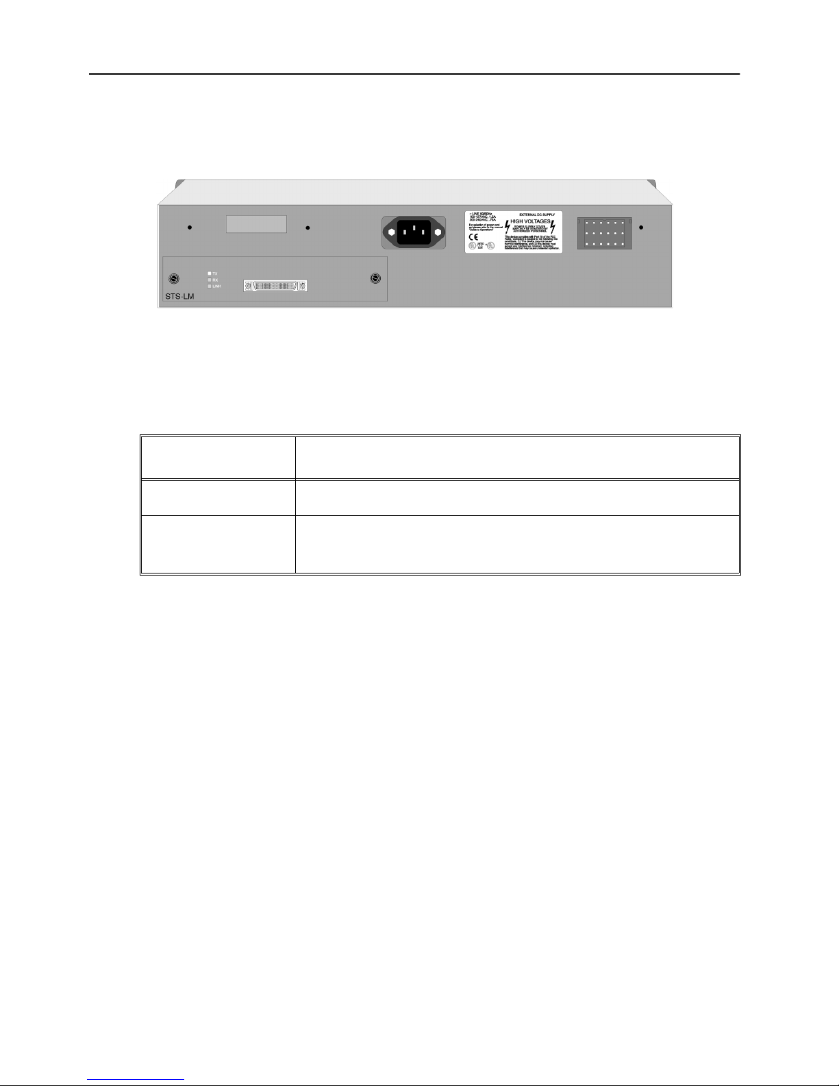
The back panel of the switches are illustrated in Figure 5.
Figure 5. The Back Panel
Table 4 lists the back panel connectors on the switch.
Name Description
AC connection Standard AC power connection.
Redundant power
Connector for the optional redundant power supply unit.
supply
Table 4. Back Panel Switches and Connectors
SmartStack STS16-20RM/STS16-20FRM Token Ring Switches, P/N: 9032957-01 Introduction
Page 25

Features and Specifications
Features and specifications for the STS16-20RM and the STS16-20FRM are listed
below.
Features
Performance and Advanced Features
Three switching modes:
•
— Low latency cut-through
— Store and forward
— Auto (Adaptive cut-through)
Enhanced bridging modes:
•
11
— Transparent bridging
— Source route switching
— Source route bridging (SRB)
— Source route transparent bridging (SRT)
Support for duplicate MAC address schemes
•
Automatic port sensing of operating mode and media speed
•
Multiple Token Ring port operation modes:
•
— Half-duplex concentrator and station
— Full-duplex concentrator and station (Dedicated Token Ring)
— RI/RO-like connection
Spanning Tree Protocol support:
•
— IEEE 802.1D
— IBM Spanning Tree Protocol
CrossLink high-speed inter-switch connection
•
(up to 256 Mbps using eight ports)
Advanced filtering (MAC address / Protocol)
•
VLAN (Virtual LAN) support
•
Support for transmission priorities
•
Congestion control
•
Introduction SmartStack STS16-20RM/STS16-20FRM Token Ring Switches, P/N: 9032957-01
Page 26

12
SRB Redundancy
•
Support for ClearSession high availability features
•
Management
Extensive and sophisticated network management:
•
— SNMP management
— Out-of-band management via Telnet and VT100 consoles
— Graphical management application for Windows 95 and Windows NT (for
information on additional management applications for Unix, please
contact your local sales representative)
Support for RMON and standard MIBs
•
Network statistics
•
LAN probe port mirroring
•
Fault isolation and detection
•
Download via TFTP or X-modem of new switch microcode
•
Up- and download of switch configuration via TFTP
•
Scalability and High Availability
Up to 5,500 active LAN stations per group of four ports (1-4, 5-8, 9-12,
•
13-16, 17-20) with a maximum of 10,000 active LAN stations per switch
Stackable architecture
•
Optional redundant power supply
•
Six switches can receive backup power from one SmartStack STS-RPC
Redundant Power Centre equipped with six SmartStack STS_PSU Redundant
Power Supply Unit.
High density switch with seamless integration of LAN & ATM via LAN
•
emulation bridging
Installation
No special crossover cable required
•
Rack or surface mounting
•
Plug and Play for transparent forwarding:
•
— Automatic learning of network configuration
— Transparent to high-level protocol
Automatic sensing and configuration of ports
•
SmartStack STS16-20RM/STS16-20FRM Token Ring Switches, P/N: 9032957-01 Introduction
Page 27

A factory-assigned MAC address (the switch can also be configured with a
•
locally administered MAC address)
Specifications
The tables on the following pages list the product specifications for the STS1620RM and the STS16-20FRM.
Capacity
Specification Value
13
Number of Token Ring ports
(base configuration)
Maximum number of
additional Token Ring ports in
expansion modules
Number of Token Ring switches
in stack
2 Expansion slots, choice of
Global lookup table size
(stations and bridges)
20
8
8 using the SmartStack STS-8SU Stacker
Unit
5 using the SmartStack STS-5SU Stacker
Unit
2 using the SmartStack STS-LM Link
Module
4 x 4/16 Mbps RJ-45 Token Ring
4 x 4/16 Mbps Fiber Token Ring
1 x ATM155 Card (UTP and MMF)
2 x High-Speed Token Ring (UTP and Fiber)
10,000
Local lookup table size, total for
4 ports
(stations and bridges)
Maximum number
of logical rings
Maximum number of VLANs
Table 5. Capacity Specifications
Introduction SmartStack STS16-20RM/STS16-20FRM Token Ring Switches, P/N: 9032957-01
5,500
63
63
Page 28

14
Performance
Specification Value
Maximum frame rate per port
Maximum aggregate frame rate
per 4 ports
Throughput per port
Aggregate switching rate
(unicast or broadcast) for entire
switch
Within switch latency
(cut-through)
Table 6. Performance Specifications
Physical Characteristics
Specification Value
57,000 pps in each direction (measured with a
frame size of 19 bytes)
200,000 pps in each direction. Full media
speed for frame sizes above 28 bytes
16 Mbps in each direction for all frame sizes
1,500,000 pps for smallest frame sizes
35 µs
Rack mount
Dimensions
Weight
Power
Frequency
AC current rating
Thermal dissipation
(without modules)
MTBF
19" rack mount (hardware included)
Width: 19" (48.3 cm)
Depth: 15.74" (40.0 cm)
Height 3.46" (8.80 cm)
19.4 lbs. (8.8 Kg)
100 to 240 VAC autosensing
50/60 Hz
1.5 A @ 100 V; 0.75 A @ 220 V
STS16-20RM:
STS16-20FRM
90 W, 307 BTU/h
: 80 W, 273 BTU/h
STS16-20RM: 77,240 hours
STS16-20FRM: 40,342 hours
Calculated using Bellcore TR-332, issue 6
Table 7. Specifications of Physical Characteristics
SmartStack STS16-20RM/STS16-20FRM Token Ring Switches, P/N: 9032957-01 Introduction
Page 29

Specification Value
15
Operating Temperature:
Non-operating Temperature:
Humidity:
Operating
Non-operating
Electromagnetic compatibility
immunity
Electromagnetic compatibility
emission
Safety
10 to 40°C (50 to 104°F)
-10 to 70°C (13 to 158°F)
8 to 80% (non-condensing)
90% @ 45°C (113°F)
EN 50082-1
EN 61000-3-2
EN 61000-3-3
FCC Part 15, subpart b, Class A
EN55022 Class A
CISPR 22 Class A
IEC 950
UL1950
CSA C22.2 No. 950
EN60950
MANAGEMENT port
Software updates
Protocol compatibility
Spanning Tree Protocol
support
MIBs supported
TIA/EIA-232-F, DB9 male connector
Flash PROM, TFTP, X-modem
Transparent to higher layer protocols
IEEE 802.1D compliant
IBM Spanning Tree
SNMP MIB II (RFC1213)
SR Bridge MIB (RFC1525)
Bridge MIB (RFC1493)
Evolution of the Interfaces Group of MIB-II
(RFC1573)
RMON MIB/TR extensions - selected
groups only (RFC1757/1513)
IEEE 802.5 MIB (RFC1749/1748)
IEEE 802.5r DTR MIB
IEEE 802.5r DTR MAC MIB
STS16-20RM MIB
VTP MIB
Table 7. Specifications of Physical Characteristics
Introduction SmartStack STS16-20RM/STS16-20FRM Token Ring Switches, P/N: 9032957-01
Page 30

16
Specification Value
Network management
Table 7. Specifications of Physical Characteristics
SNMP Management Platform
-
Console
-
Telnet sessions
-
SmartStack Manager for Windows 95
-
and NT
Additional management applications
-
available on Unix platforms:
—Tivoli TME 10 NetView for AIX
❏
SmartStack STS16-20RM/STS16-20FRM Token Ring Switches, P/N: 9032957-01 Introduction
Page 31

2. Switch Overview
The STS16-20RM and the STS16-20FRM are both IEEE 802.5-compliant devices
designed to boost throughput on Token Ring networks. They operate as a Media
Access Control (MAC)-layer device that is protocol independent.
This chapter describes how the switch operates as a single stand-alone unit. The
switch contains the following main elements:
Switching Bus—the architecture of the switch centers around the AXIS bus, a
•
520 Mbps switching fabric through which all switched ports communicate.
The AXIS bus is a partially asynchronous time division multiplexed bus used
for switching packets between heterogeneous LAN modules.
Token Ring Ports—each port can attach to a classical Token Ring segment or
•
to a dedicated station. Now users running basic applications are able to share
bandwidth, and users running bandwidth-intensive applications can receive
their own dedicated 16 Mbps port. Each dedicated port can also be set up in
full-duplex communication mode, so that each 16 Mbps port doubles to 32
Mbps.
17
SmartStack Interface Modules (SSIMs)—each switch supports two expansion/
•
uplink modules. These modules include RJ-45 or fiber ports to provide up to
eight additional 16 Mbps Token Ring ports. High-speed connections such as
155 Mbps ATM, 100 Mbps HSTR, and 100 Mbps Fast Ethernet provide
connections for servers or backbone connectivity.
Stack Link Module—the switch supports a stack link module that can be used
•
to connect two switches from the STS16-20RM series in a back-to-back
configuration. Alternatively, up to five switches can be connected together
using an internal stacker module, and up to eight switches can be connected
together using the external stacker unit and an additional switch stack unit. By
connecting switches together through the stack link module, the switches
virtually combine to form a single unit, providing scalability, simplified
management, and enhanced performance.
Switch Overview SmartStack STS16-20RM/STS16-20FRM Token Ring Switches, P/N: 9032957-01
Page 32
18
Multiple Simultaneous Conversations
A limitation of Token Ring is that it supports only one packet at a time. The STS1620RM and the STS16-20FRM improve data throughput by supporting multiple,
simultaneous, full-duplex conversations. By using High-Speed bus switching
technology, the switch creates multiple data paths. These switched connections
between Token Ring segments last only for the duration of a byte transmission.
New connections are made “on-the-fly” between different ports on the switch for
the next byte.
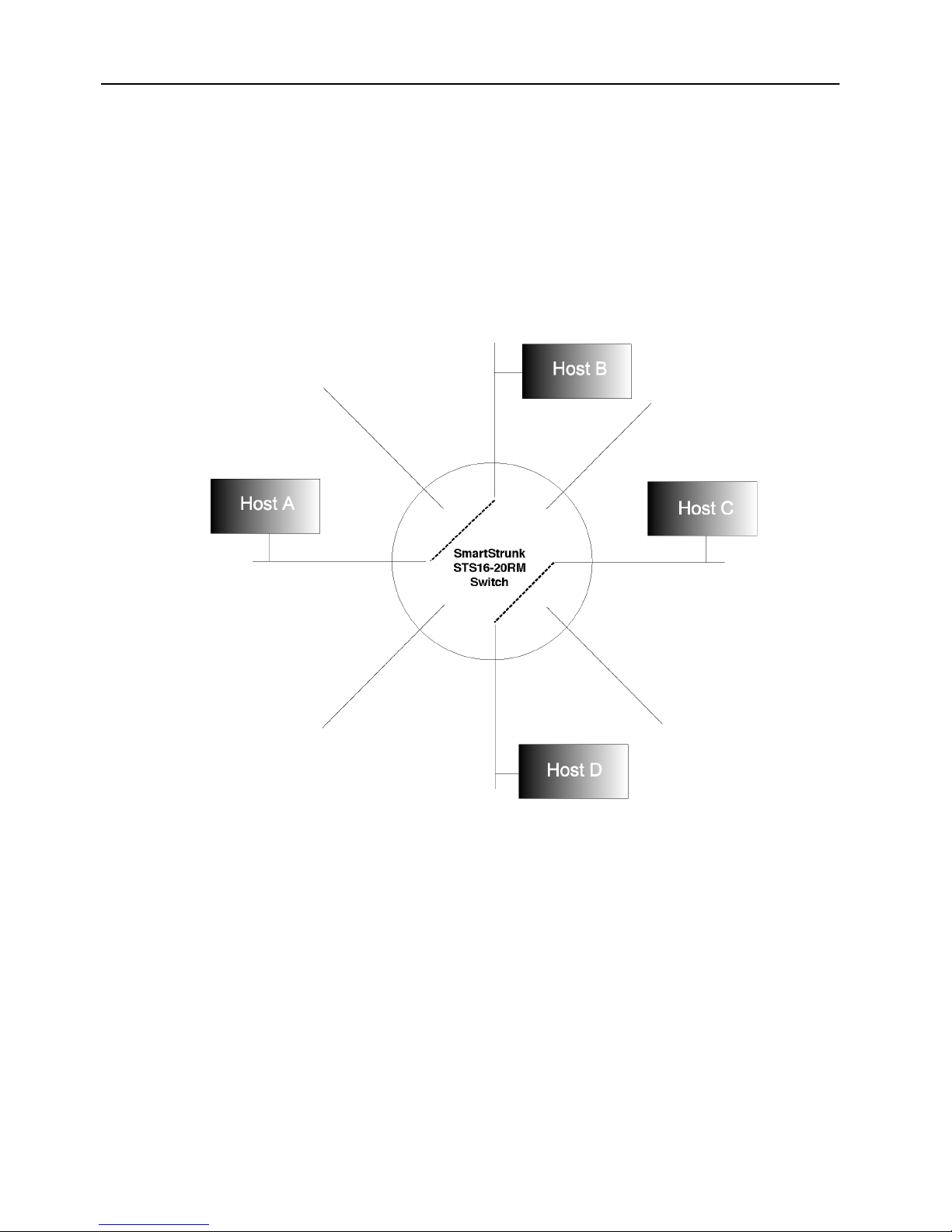
Figure 6. Multiple Conversations Through a STS16-20RM or
STS16-20FRM Switch
For example, as shown in Figure 6, while host A is transmitting a byte to host B,
the switch connects only the lines from A to B since there is no need to send packets
to all other ports. At the same time, a second switching circuit can connect host C
to host D. The result: Two packets are sent simultaneously.
➽ Note:
The switch transmits broadcast and multicast packets on several switch ports
simultaneously.
The increase in throughput is directly proportional to the number of physical tokenrings that are interconnected through the switch. A switch with 20 ports
interconnected provides up to ten concurrent paths. With ten simultaneous
SmartStack STS16-20RM/STS16-20FRM Token Ring Switches, P/N: 9032957-01 Switch Overview
Page 33

conversations, the switch creates 160 Mbps throughput in half-duplex mode, or 320
Mbps throughput in full-duplex mode.
A single segment can be dedicated to a single host or shared by several. To optimize
throughput, high-speed servers can be given dedicated switch ports.
By transporting multiple Token Ring packets simultaneously, it boosts overall
network throughput.
Low Latency
When operating in cut-through mode, the switch minimizes latency—the time it
takes to forward a packet from one Token Ring segment to another—by beginning
switching immediately after looking at the first six bytes of the destination address
in the packet. If the packet needs to be switched to another LAN segment, its data
begins flowing through the destination port before the entire packet has been
received. The result: packets can appear at the output port 35 microseconds after
entering the input port. Network devices that use store-and-forward technology
introduce much longer delays because they wait to receive the entire packet before
forwarding it.
19
By minimizing delay, the switch can move more packets freely throughout the
LAN without degrading performance.
Address Manag ement
At power up, the system address tables do not contain any information. Whenever
a switch receives a packet with an unknown source or destination address, it learns
the new source address and stores its location in coming port in the address table.
If the destination address is unknown it sends the packet to all ports that can receive
data from the incoming port. When the response packet comes back, the switch will
learn the responder’s location and adds it to the address table. Once the address
table entries are created, the switch uses these learned address to switch all
subsequent packets to the port where the destination address is located.
The system address table maintains up to 10,000 entries, and each port address table
maintains 5,500 active Token Ring addresses (each port address table is shared by
four ports, using the following: 1-4, 5-8, 9-12, 13-, etc.). If an address has not been
active for a configurable aging time, it is removed from the tables. This ensures that
the port’s address table is populated only by the most recently used address.
This capability allows users to transparently connect to high-volume backbone
networks.
Switch Overview SmartStack STS16-20RM/STS16-20FRM Token Ring Switches, P/N: 9032957-01
Page 34
20
Multiple Bridging Modes
The STS16-20RM and the STS16-20FRM each supports four different switching
modes to provide maximum flexibility in all installation environments. The
switching modes are
source route transparent
(BRF and CRF) as outlined in the following.
source route switching
(SRT) and SRT/SRB. The switch operates on two levels
(SRS),
source route bridging
(SRB),
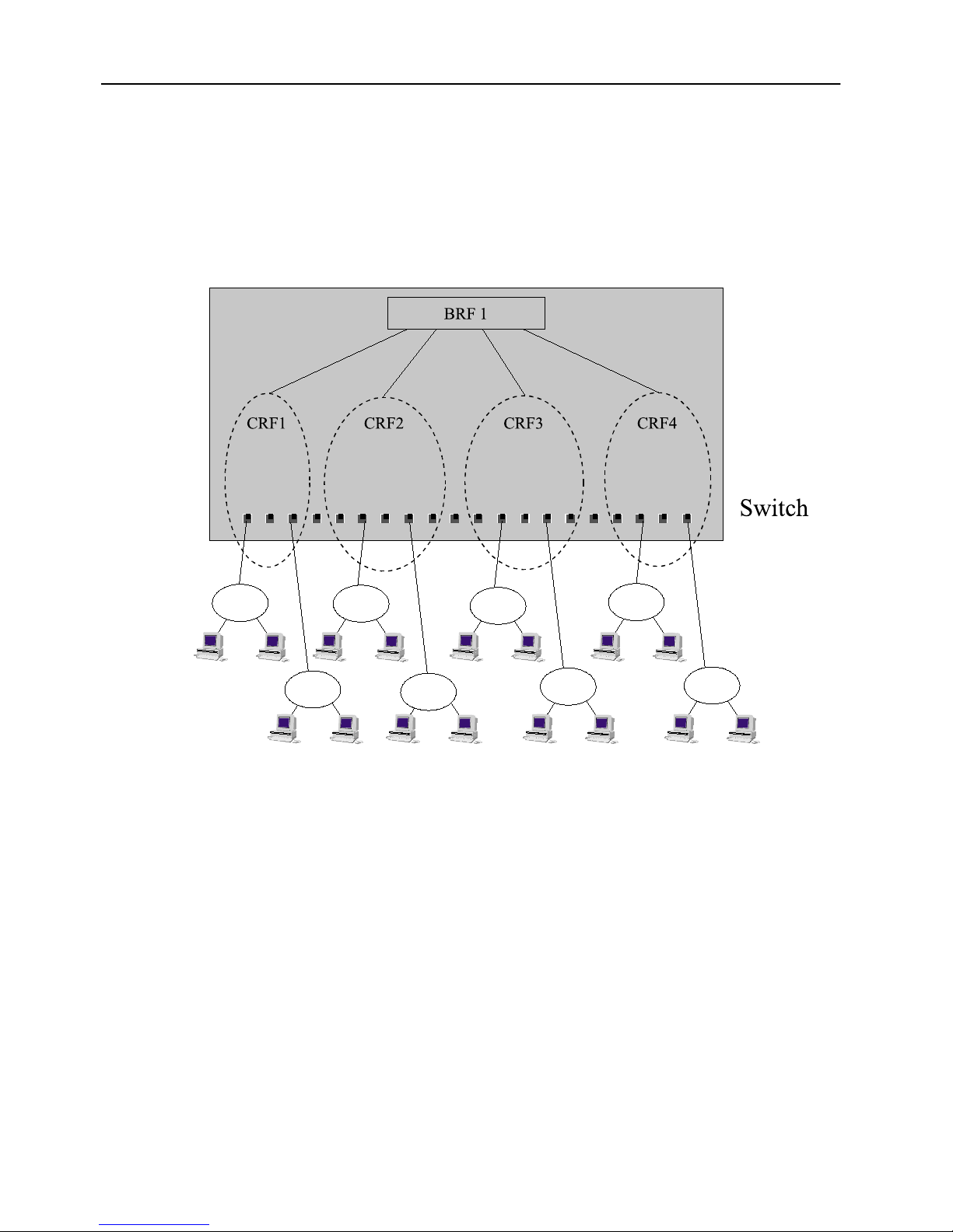
Figure 7. Typical Configuration with Switches
Using Multiple Bridging Modes
The switch bridging modes are founded on the concept of
logical segments
in Ethernet. The logical ring is represented on the switch by the
DTR (IEEE 802.5r) standard’s
may consist of interconnected CRFs on different switches.
Each port on the switch belongs to a CRF, which is a logical grouping of ports
within the switch. A CRF can consist of any number of ports within a switch or a
switch stack. The ports within a CRF do not have to be adjacent.
The logical rings and, subsequently, the CRFs, are assigned a unique ring number
each when the switch performs source routing functions. The bridging is performed
through the logical entity of the
SmartStack STS16-20RM/STS16-20FRM Token Ring Switches, P/N: 9032957-01 Switch Overview
concentrator relay function
bridge relay function
(BRF).
logical rings
(LR) or
(CRF). A logical ring
Page 35

21
The CRF communicates via a logical, virtual port with the bridge relay function,
which functions as a multiport (virtual) bridge between the logical rings. The
switch can support up to 63 logical rings.
There are two levels of relay functions supported by the switch. The first level is
the CRF to which the ports are assigned. The second level is the BRF. This is the
parent relay function to which CRFs are assigned. The switch maintains certain
configuration information and management statistics on a per BRF/CRF basis.
Therefore, when you access VLAN specific switch configuration or management
screens (such as the Current Spanning Tree Information screen), you will be
prompted to specify the desired BRF or CRF.
Source Route Switching (SRS)
This mode is used between ports comprising a logical ring.
SRS switching combines the normal transparent bridge function with the ability to
forward frames based on source route information to locally attached source-route
bridges. The switch does not otherwise act as a source route bridge. For non sourcerouted packets, the switch decision is based upon destination MAC Addresses. For
source-routed packets, it is based on the source-route information combined with
the destination MAC address.
The switch learns MAC addresses and source-routing route descriptors of Source
Route Bridges attached to local switch ports.
Parallel paths are eliminated via the IEEE 802.1D Spanning Tree Protocol.
Source Route Bridging (SRB)
The BRF acts as a multiport source route bridge between CRFs with the following
characteristics:
Each logical ring has a different ring number
•
Source-routed frames are forwarded between the logical rings by the bridge
•
relay function based on the route information field
Non-source-routed frames are not forwarded between logical rings
•
The bridge relay function has a single bridge number and multiple ring
•
numbers (one per logical ring)
SRS is used between the ports of each logical ring. The bridge relay function runs
the IBM Spanning Tree Protocol to eliminate parallel paths with other source-route
bridges. The IEEE 802.1D Spanning Tree Protocol is still used with each logical
ring. Duplicate MAC addresses are allowed
rings.
if they are on different logical
only
Switch Overview SmartStack STS16-20RM/STS16-20FRM Token Ring Switches, P/N: 9032957-01
Page 36

22
Source Route Transparent (SRT)
The BRF can combine transparent switching with source route bridging. Nonsource-routed packets are switched across logical rings by transparent bridging.
Source-routed frames are switched across logical rings by source route bridging
and within each logical ring by source route switching.
The Bridge Relay Function runs the IEEE 802.1D Spanning Tree Protocol.
Duplicate MAC addresses are
allowed.
not
SRT/SRB
This is a special mode combining SRT and the SRB switching modes. Each logical
ring will operate either in SRT mode or in SRB mode. Transparent bridging will
only take place between logical rings in SRT mode. Source route bridging will take
place between all logical rings.
The purpose of the SRT/SRB mode is to allow duplicate MAC addresses to be used
when in SRT mode. The ports on which the duplicate MAC addresses reside can be
reached only by source routing.
The bridge relay function runs the IBM Spanning Tree Protocol on the SRB logical
rings to eliminate parallel paths with all source route bridges. It runs IEEE 802.1D
Spanning Tree Protocol on the SRT logical rings to eliminate parallel paths with
other SRT bridges. The two resulting spanning trees are joined together.
The IEEE 802.1D Spanning Tree Protocol is still used to eliminate parallel paths
within each logical ring whether it is SRB or SRT.
The benefit of the SRT/SRB mode is that it allows part of the network to be run in
SRT mode to accommodate applications that do not support source routing, while
still supporting duplicate MAC addresses on a number of SRB ports (for example,
for SNA gateway applications).
SmartStack STS16-20RM/STS16-20FRM Token Ring Switches, P/N: 9032957-01 Switch Overview
Page 37

Filtering
Filtering is important for a LAN switch. Filters can be used to reduce broadcast
traffic, block certain protocols and provide security functions.
The switch provides filters for:
Destination or source MAC addresses
•
Destination service access point (DSAP)
•
Subnetwork Access Protocol (SNAP) type
•
Each protocol filter can be applied on a per-port basis for both input and output
traffic. This feature allows certain protocols to be blocked from certain ports. For
example, filters can be established to allow only Systems Network Architecture
(SNA) traffic to flow to ports with SNA gateways.
Source and destination MAC address filtering can be applied to all incoming
frames. The MAC address filters act in one of three ways:
23
Block destination address at a specific port—this prevents the specified port
•
from sending frames to a specified destination.
Allow destination address at specific ports—this indicates that the specified
•
port must send frames to the specified destinations
Force destination address to a specific port—this allows forwarding to a
•
unicast address that has not been learned. It can also be used to limit the
forwarding of Multicast addresses to a subset of ports. This last filter applies
to non-source-routing frames
Congestion Control
At regular intervals, the switch CPU inspects the queues on all output ports. If a
queue size is above a certain threshold, the port is instructed to:
Set the transmit priority for low priority frames to a specified high level
•
Delete old frames from the queue until it reaches a specified size
•
When the queue size again comes below a normal threshold size the port is
instructed to set the transmit priority back to the normal level.
only
.
only
.
Switch Overview SmartStack STS16-20RM/STS16-20FRM Token Ring Switches, P/N: 9032957-01
Page 38

24
Three Switching Modes
This section describes the three switching modes available on the switch.
Cut-Through
In this mode the switch starts forwarding the packet to the output port as soon as
the destination address or the source route of the incoming packet has been
resolved. This technique ensures very low latency, typically in the range of 30-100
µs. However, if errors occur on the input port during the reception of a packet, the
error will still be forwarded to the output port. Note that cut-through can only be
used in transmissions between ports which operate at 16 Mbps.
Store and Forward
In this mode, the switch receives the total packet from the input port, checks it for
any errors and then starts forwarding the packet to the destination port. This
technique will ensure that no faulty packets are transmitted by output port. The
negative impact however, is higher latency, typically in the range of 40–2,000 µs
depending on the packet size. Though slower than cut-through mode, this is still
much faster that conventional bridges.
Auto (Adaptive Cut-Through)
This is a technique whereby the switch will automatically swap between store-andforward and cut-through modes based on an error threshold. If the number of
received faulty packets is low, then cut-through mode is used; if the number of
faulty packets is high, the store and forward mode is used. This provides optimized
performance but introduces variable latency.
SmartStack STS16-20RM/STS16-20FRM Token Ring Switches, P/N: 9032957-01 Switch Overview
Page 39

Token Ring Port Operation Modes
Each Token Ring port may operate in one of the following modes:
Half-duplex concentrator port
•
The port behaves like an active MAU port for classical Token Ring. Connects
to a single station in half-duplex mode. This is also known as Token Passing
(TKP) port mode. Compatible with older adapters.
Half-duplex station emulation
•
The port is connected to a port on a MAU. Connects to a classical Token Ring
segment with multiple stations. This is also known as Token Passing (TKP)
station mode.
Full-duplex concentrator port
•
Connects to a single station or to another switch in full-duplex mode. This is
also known as Transmit Immediate (TXI) port mode.
25
Full-duplex station emulation
•
Connects to another Token Ring switch. This is also known as Transmit
Immediate (TXI) station mode.
RI/RO-like connection
•
Allows connection of the RI/RO port from a MAU or CAU directly to the
switch. (STS16-20RM on ports 19 and 20, STS16-20FRM on all 20 fiber
ports.)
The mode of operation can be configured manually or sensed automatically with the
exception of RI/RO, when equipment is connected to the port. The media speed (4 or
16 Mbps) can also be manually configured or automatically sensed in all port modes.
The mode of operation can be configured manually or sensed automatically with
the exception of RI/RO, when equipment is connected to the port. The media speed
(4 or 16 Mbps) can also be manually configured or automatically sensed in all port
modes.
Switch Overview SmartStack STS16-20RM/STS16-20FRM Token Ring Switches, P/N: 9032957-01
Page 40

26
RI/RO-Like Connection
Two different types of RI/RO connections are used on the UTP cables and fiber
RI/RO connections on the switch.
UTP RI/RO Connection
A UTP RI/RO connection is only available on STS16-20RM, on ports 19 and 20.
This feature allows the switch to connect to CAU/LAM systems using the RI/RO
connections thus providing a RI/RO-like functionality. This enables the switch to
be easily installed in existing Token Ring networks.
A loop-back function has been implemented on these ports so that if the port is
disabled or the switch is powered off there will not be a break in the attached main
ring. This means that attaching a cable from the RI port of a MAU port to one of
the two switch ports in effect joins the primary and the backup ring in a MAU/CAU
main ring system. Connecting the other end of the RI/RO connection to the other
switch port,
the same segment.
enabled
there is a break in the main ring, the STP will place both ports in forward mode, and
all MACs on both segments will be relearned.
creates redundant paths
Therefore, the IEEE Spanning Tree Protocol (STP) must be
, which will place one port in forward and the other in blocked mode. If
because the two switch ports are connected to
If a switch port has been configured to RI/RO mode, it will automatically sense
whether the port has been connected to RI or RO of the MAU.
➽ Note:
connected according to the configuration. Any errors, such as attaching port 19 or
20 to a normal MAU port when the STS16-20RM port has been configured for
RI/RO, will cause a complete disruption of the ring to which the port is attached.
Therefore, be careful when using the RI/RO feature.
Fiber RI/RO Connection
Fiber RI/RO is available for all twenty ports on the STS16-20FRM Switch and on
fiber expansion modules. This mode allows the switch to connect to fiber devices
that does not conform to 802.5j specifications.
It is not possible to automatically verify whether an UTP/STP port has been
SmartStack STS16-20RM/STS16-20FRM Token Ring Switches, P/N: 9032957-01 Switch Overview
Page 41

Transmission Priority Queues
To address the needs of delay-sensitive data, such as multimedia, the Token Ring
ports of the switch have two transmit queues, a high-priority queue and a lowpriority queue.
The queue for a frame is determined by the value of the priority field in the frame
control (FC) byte. If FC priority is above a configurable level (default 3), the frame
is put into the high-priority queue. If an output port becomes congested, you can
dynamically configure the port to transmit all frames at high priority regardless of
the FC byte contents.
ClearSession Support
The STS16-20RM series switches support ClearSession high availability and
network redundancy features.
27
ClearSession is a framework for mission critical networks. It prevents session loss by
providing a network failure recovery time of, typically, less than three seconds.
ClearSession consists of a several product features. Some of these, ClearServer,
CrossLinks and Dynamic Source Route Recovery, are supported by the STS1620RM series switches. These features provide the following functionality:
ClearServer
treated as one virtual adapter in the server, thus allowing multiple connections
between a server and the backbone switch or switches. During normal operation the
traffic is distributed on the links. The STS16-20RM series switches support
ClearServer for LAN to be used on servers connected to the switch.
CrossLinks.
20RM series switches may be expanded to a CrossLink. A CrossLink is an
aggregation of two to eight identical parallel links, working as one link of the
aggregate capacity, providing protection from physical link failure. Should one of
the links fail, the traffic is redistributed among the remaining operational links.
Dynamic Source Route Recovery
STS16-20RM series switches, performing source route bridging between a sharedmedia access ring and a common backbone ring, to function as backup for each
other. Should one of the switches fail or lose connectivity to one of the access rings,
the other switch immediately takes over and bridges source-routed traffic marked
with the failed path. DSRR protects source-routed traffic to and from shared access
segments, such as user rings, with redundant connections to two Token-Ring
switches. Traffic to and from such rings that is non-source-routed relies on the
spanning tree.
. Token-Ring ClearServer for LAN, allow multiple adapters to be
Any Token-Ring link or dedicated Token-Ring link between STS16-
. DSRR is a feature that enables two or more
Switch Overview SmartStack STS16-20RM/STS16-20FRM Token Ring Switches, P/N: 9032957-01
Page 42

28
CrossLink Connections
Two or more Token-Ring ports can be configured to comprise a CrossLink.
A CrossLink is a collection of identical parallel links between two switches or
between a switch and an end node, aggregated to appear as one single link of the
aggregate capacity. The traffic distribution mechanism attempts to balance the load
on the individual links. If one of the links in a CrossLink fails, the traffic is
automatically moved from this link and distributed among the other links, thus
providing active resilience.
The CrossLink ports on a STS16-20RM series switch can be used to connect to
another STS16-20RM series switch, or a server with multiple RapidFire adapters
using ClearServer for Token-Ring. (Please note that ClearServer for Token-Ring is
supported on selected models of RapidFire adapters only. For details, refer to the
ClearServer for LAN product information.)
The CrossLinks provide load distribution as well as resilience. In normal operation,
the traffic is distributed on the physical ports of the CrossLink according to the
frame MAC addresses. This ensures the sequence of a flow. Should a link fail or
otherwise become inoperative, the switch dynamically redistributes the traffic to
the remaining links. The CrossLink remains in operation as long as there is at least
one link in operation. If a failed link is restored, traffic is once more redistributed
to make use of the restored link.
A CrossLink is in many ways operating as one single link. For example, the
spanning tree protocol will only have one port entity covering all ports in the
CrossLink. The ports will all have the same operating state. As for VLAN and CRF
configuration, the CrossLink is also seen as one link. Configuration changes apply
to all links in the CrossLink.
On the STS16-20RM or STS16-20FRM switch, CrossLinks can also be configured
on the High-Speed Token-Ring ports of the SSIM-R2-02/SSIM-R8-02 High-Speed
Token Ring SmartStack Interface Modules or on the Fast Ethernet ports of the
SSIM-H2-02 Fast Ethernet - Translational Switch SmartStack Interface Module.
CrossLinks on Fast Ethernet ports can only consist of two ports available on the
sameSSIM-H2-02 Fast Ethernet - Translational Switch SmartStack Interface
Module.
The CrossLink concept is designed to be compatible with the coming Link
Aggregation standard, IEEE 802.3ad.
The STS16-20RM or STS16-20FRM switch allows up to eight CrossLinks, each
consisting of up to eight Token-Ring links.
For details about CrossLink configuration, please refer to the section “CrossLink”
on page 109 in Chapter 6, “Switch Configuration”..
SmartStack STS16-20RM/STS16-20FRM Token Ring Switches, P/N: 9032957-01 Switch Overview
Page 43

Spanning Tree Protocol Support
29
IBM initially supported only
networks were built to use it. The main consideration for SRB implementations in
switches is the spanning tree algorithm for spanning tree explorers (STEs). IBM
originally implemented a form of the Institute of Electrical and Electronics
Engineers (IEEE) spanning tree algorithm. This algorithm, commonly referred to
as the IBM spanning tree, limits the STE frames to one copy per destination ring.
Some SRB implementations have also implemented the IEEE Spanning Tree
Protocol to be compatible with source route transparent bridges. The IEEE
Spanning Tree Protocol is not compatible with the IBM Spanning Tree Protocol.
The switch supports both the IEEE 802.1D and IBM Spanning Tree Protocols.
VLAN Support
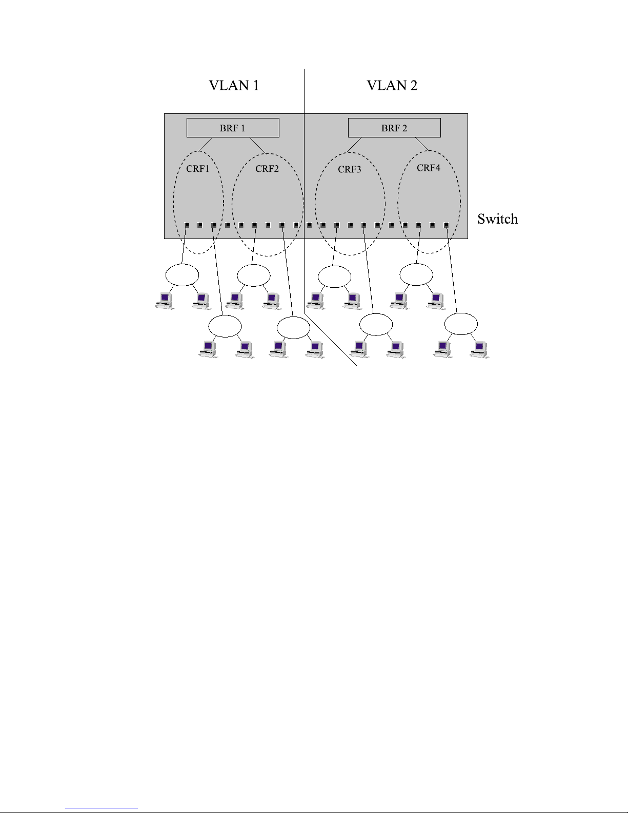
The virtual LAN (VLAN) concept creates a virtual switch within a physical switch
or stack of switches. A VLAN consists of CRFs and has its own bridge relay
function attached. Frames are not forwarded across VLANs and ring numbers must
be unique within a VLAN.
A VLAN consists of a number of ports of a switch or stack of switches
•
source route bridging
(SRB) in its bridges, so most
No frames are forwarded between ports belonging to different VLANs
•
Port groups on different VLANs may be assigned the same ring number, but
•
ring numbers must be unique within the same VLAN
For each VLAN, the stack can be assigned a separate IP address
•
The spanning tree protocol is executed independently within each VLAN.
•
However, since all BRFs use the same Bridge ID for the spanning tree
algorithm, the spanning tree protocol will not function if ports from different
BRFs within one switch are connected.
A sample VLAN with a STS16-20RM or a STS16-20FRM is shown in Figure 8.
Switch Overview SmartStack STS16-20RM/STS16-20FRM Token Ring Switches, P/N: 9032957-01
Page 44
30
Figure 8. A Switch Configured with Two VLANs
SmartStack STS16-20RM/STS16-20FRM Token Ring Switches, P/N: 9032957-01 Switch Overview
Page 45
Dynamic Source Route Recovery
Dynamic Source Route Recovery (DSRR) is a proprietary protocol that enables a
group of switches to handle a link or switch failure without session loss.
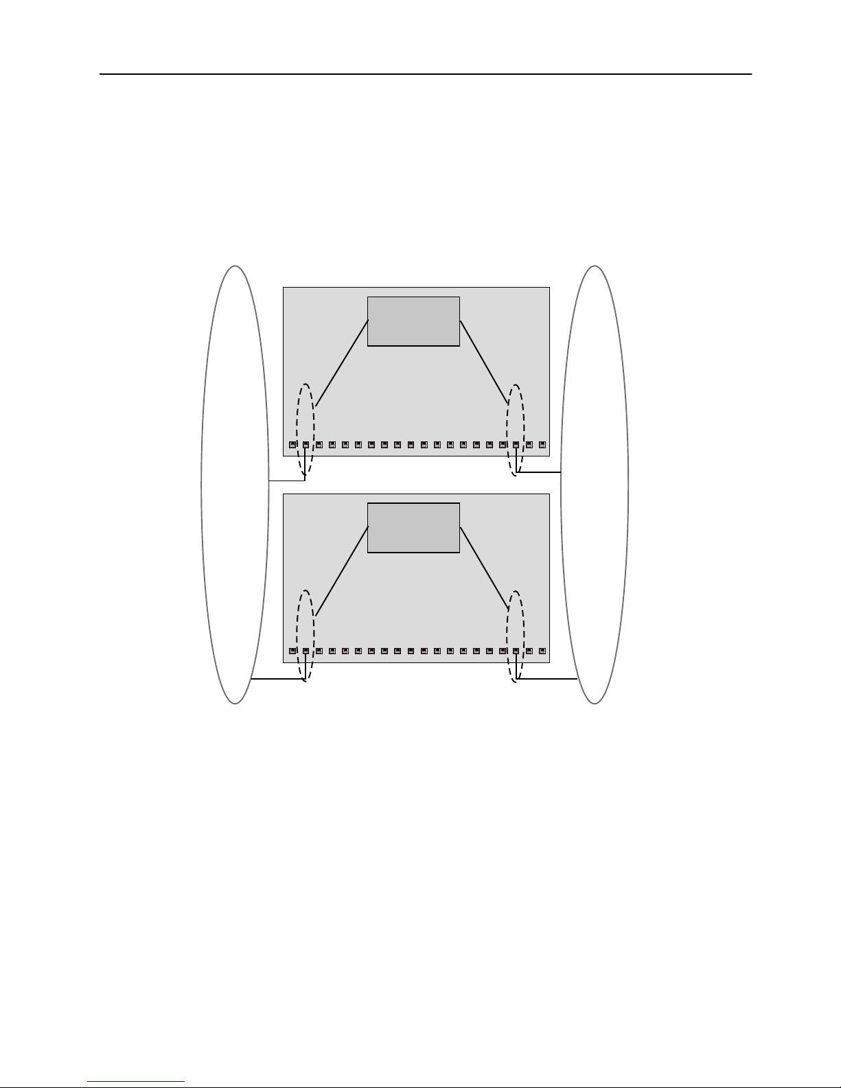
A basic redundant setup must have a minimum of two switches performing source
route bridging between a legacy Token-Ring and an emulated Token-Ring (or
another legacy ring) as illustrated in Figure 9.
BRF
Bridge No. B1
31
CRF
BRF
Bridge No. B2
CRF
CRF
A
M
CRF
A
M
T
T
Figure 9. Example of Dynamic Source Route Recovery, Base Configuration
This configuration already has redundant paths between the two rings, but since
moving traffic from one path to the other involves changing source route, this
would involve session loss.
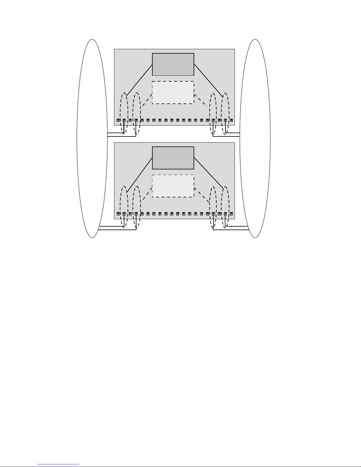
When DSRR is enabled, an extra path is automatically created between the two
rings for each switch, as shown in Figure 10. During normal operation, these extra
paths do not forward any traffic.
Switch Overview SmartStack STS16-20RM/STS16-20FRM Token Ring Switches, P/N: 9032957-01
Page 46
32
BRF
Bridge No. B1
Backup BRF
Inactive
BRF
Bridge No. B2
Backup BRF
Inactive
A
A
T
T
M
M
A
A
T
T
M
M
Figure 10. Example of Dynamic Source Route Recovery, Normal State
If one of the switches (Figure 10) or its link to any of the Token-Rings fail, (one of)
the remaining active switch(es) will after a short interval activate its backup path to
take over the traffic of the failed switch (see Figure 11). When the failing switch
has been repaired/replaced, the traffic will automatically revert to it.
SmartStack STS16-20RM/STS16-20FRM Token Ring Switches, P/N: 9032957-01 Switch Overview
Page 47
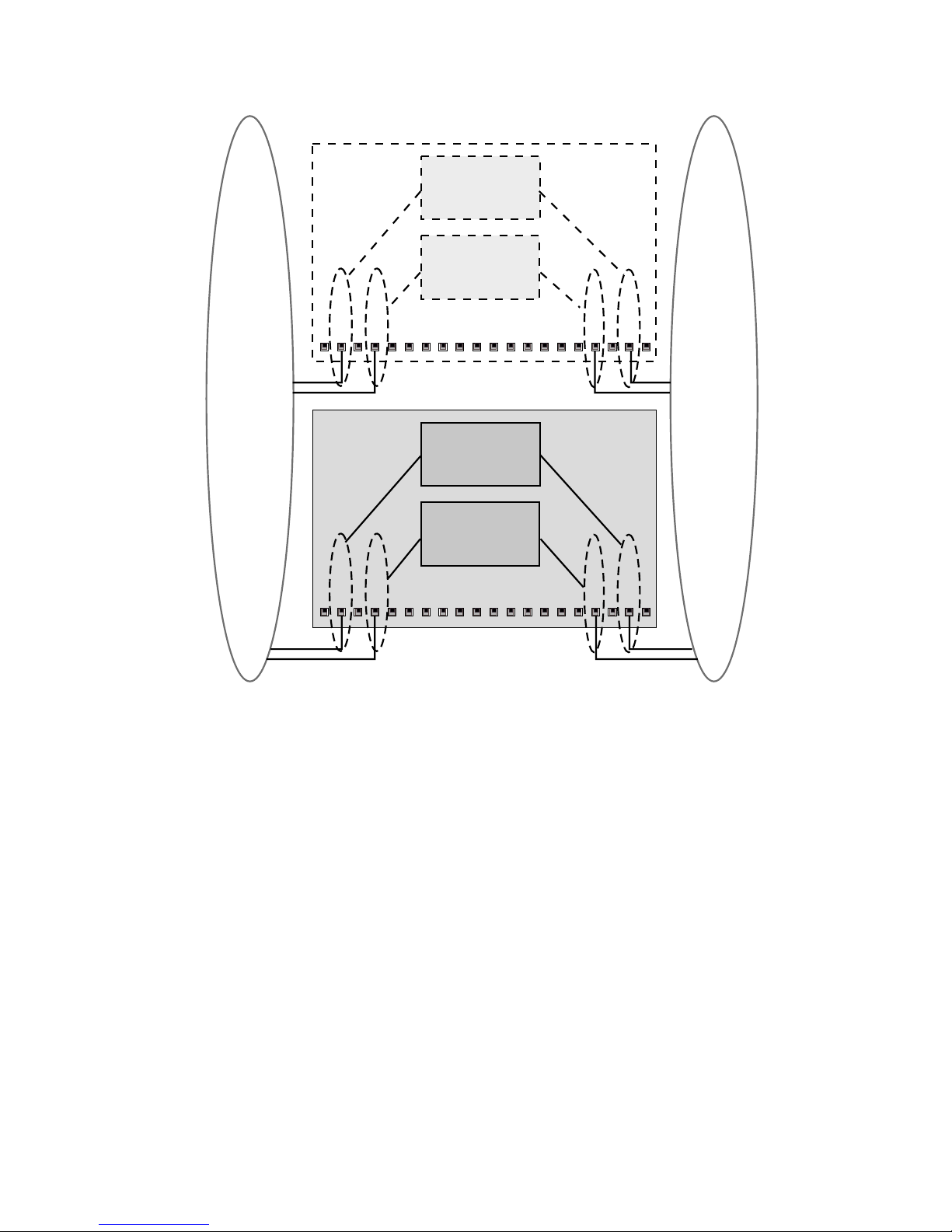
BRF
Bridge No. B1
Backup BRF
Inactive
BRF
Bridge No. B2
33
A
A
T
T
M
M
Backup BRF
Bridge No. B1
Active
A
A
T
T
M
M
Figure 11. Example of Dynamic Source Route Recovery, Switch 1 Failed
Note that since a separate link is required for forwarding traffic with a given Route
Descriptor, one switch can only carry backup traffic for one failed switch at a time.
This means that a total of 2×n switches is required to handle simultaneous failure
of n switches.
While the above example shows redundancy for a BRF with two CRFs, it is also
possible to provide (partial) redundancy for a BRF with more than two CRFs. This
must, however, be accomplished by creating separate DSRR instances for selected
CRF pairs. Note that since at least one of the CRFs must be connected to a legacy
Token-Ring, it is not possible to provide full redundancy for a BRF with more than
one ATM CRF.
Switch Overview SmartStack STS16-20RM/STS16-20FRM Token Ring Switches, P/N: 9032957-01
Page 48

34
Management
This section describes the management options for the switch.
SNMP
The switch can be managed via a SNMP manager. It supports ten Management
Information Bases (MIBs). Six of the MIBs are standard MIBs, which are defined
by RFCs and are included with most SNMP management applications. Four of the
MIBs are proprietary and are provided on the disk that accompanies the switch.
SNMP management is supported via IP and MAC.
The following MIBs are supported:
Specification MIB
RFC1213 MIB II
RFC1493 Bridge MIB
RFC1525 SR Bridge MIB
RFC1573 Evolution of the Interfaces
Group of MIB-II
RFC1757/1513 RMON MIB/TR extensions -
Only partial support
RFC1749/1748 IEEE 802.5 MIB
DTR MIB IEEE 802.5r MIB
DTR MAC MIB IEEE 802.5r MIB
Private MIB 1.3.6.1.4.1.285
Private MIB 1.3.6.1.4.1.9
Table 8. Supported MIBs
Most user configurable variables will be supported in either the standard MIBs or
the proprietary MIB. Configuration settings, such as port attributes, and operational
information, such as address tables, are fully accessible through SNMP. Certain
other settings, such as passwords and console settings, cannot be viewed or
modified via SNMP for security reasons.
SmartStack STS16-20RM/STS16-20FRM Token Ring Switches, P/N: 9032957-01 Switch Overview
Page 49

35
SmartStack Manager for Windows
The SmartStack Manager is an application that runs under Windows. It provides an
intuitive graphical user interface (GUI) displaying a view of the switch front panel
and supporting configuration, performance monitoring, and troubleshooting.
This application is included with the switch.
Telnet Management and VT100 Management (Console)
The Console Management function may be accessed out-of-band via the TIA/EIA232-F (that is, RS-232) port labeled MANAGEMENT or in-band via Telnet.
IBM LAN Network Manager
The switch does
support management by the IBM LAN Network Manager, but
not
it will allow LAN Network Manager LLC frames to flow through the switch so that
communication to existing LNM manageable hubs and source route bridges will be
maintained. The switch also implements a mini Ring Parameter Server to supply
attached NICs (such as CAUs) with the configured ring number.
Some error reporting functions and ring map functions might be lost for the rings
attached to through the switch, because a Token Ring switch will not (and should
not) forward MAC frames, but only LLC frames between ports.
Switch Overview SmartStack STS16-20RM/STS16-20FRM Token Ring Switches, P/N: 9032957-01
Page 50

36
RMON Support
RMON is an industry-standard method for providing network statistics monitoring
using SNMP. It also collects fault, performance, and configuration statistics. It can
monitor continuously, even when communication with the management station is
not possible or efficient. RMON can then notify the management station when an
exceptional condition occurs.
In typical SNMP management, the SNMP client has to continuously poll the switch
for fault, performance, and configuration information, waiting for the value to
change. This causes increased traffic through the network. With RMON, you can
have the switch monitor a particular statistic internally, and when the statistics
reaches a threshold, the switch will send a trap to the client. This monitoring
method reduces traffic between the SNMP client and the switch.
The switch implements a mini RMON probe for the physical ports by supporting
some of the RMON groups RFC 1757 and RFC 1513.
For full RMON an external probe must be used.
For information on supported groups, see the following table:
Name Support Info
1.
Statistics
:
Supported:
— The Token-Ring MAC-Layer Statistics Group.
The Token-Ring Promiscuous Statistics Group.
— The Ethernet Statistics Group.
2. History Supported
:
— The Token-Ring MAC-Layer History Group.
— The Token-Ring Promiscuous History Group.
3. Alarm
— The Ethernet History Group
—
Supported
—
Not supported
for all RMON variables.
for other MIB variables.
.
4. Hosts Not supported.
5. HostTopN Not supported.
6. Matrix Not supported.
7. Filter Not supported.
Table 9. Supported RMON Groups
SmartStack STS16-20RM/STS16-20FRM Token Ring Switches, P/N: 9032957-01 Switch Overview
Page 51

Name Support Info
37
8. Capture Not supported
9. Event Supported.
10. Token-Ring Supported:
— The Token-Ring Ring Station Group.
— The Token-Ring Ring Station Order Group.
— The Ring Station Config Table.
Not supported
— The Token-Ring Ring Station Config Group.
— The Token-Ring Source Routing Group.
Table 9. Supported RMON Groups
Built-in Port Counters
The switch supports a wide range of port counters, which enables you to obtain a
detailed overview of the port traffic. The counters give a comprehensive overview
in the areas of:
.
Only
supported as read
created as default can be read. The ring station
table is not supported.
:
. That is, only the entries
MAC Layer Counters
•
MAC Layer Error Counters
•
Frame Forwarding Counters
•
Switch Overview SmartStack STS16-20RM/STS16-20FRM Token Ring Switches, P/N: 9032957-01
Page 52

38
Stackable Architecture
All SmartStack STS16-20x switches are stackable.
The STS16-20RM and the STS16-20FRM switch can be stacked using the
SmartStack STS-LM Link Module, the SmartStack STS-5SU Stacker Unit or the
SmartStack STS-8SU Stacker Unit for connecting up to eight switches in a stack.
Back-to-Back
Two STS16-20RM series switches can be connected together by fitting each switch
with the SmartStack STS-LM Link Module and connecting the switches together
using an appropriate stacker link cable. This simple connection doubles the number
of ports available, giving a total maximum of 56 ports.
Internal Stacker
The SmartStack STS-5SU Stacker Unit can be inserted into the stacker port of a
switch. It allows up to five switches from the STS16-20 series to be stacked together.
One of the switches in the stack must contain the SmartStack STS-5SU. Each switch
in the stack must be equipped with a SmartStack STS-LM Link Module and an
appropriate stacker link cable. This can result in a stack of as many as five STS1620RM series switches. The SmartStack STS-5SU Stacker Unit works as a common
backplane switching fabric, which provides 1.4 Gbps of aggregate bandwidth.
External Stacker
The SmartStack STS-8SU Stacker Unit is an external stack unit that allows up to
eight STS16-20RM series switches to be stacked together. Each switch in the stack
must be equipped with an SmartStack STS-LM Link Module and an appropriate
stacker link cable. The SmartStack STS-8SU Stacker Unit works as a common
backplane switching fabric, which provides 2.2 Gbps of aggregate bandwidth.
➽ Note:
switches from the STS16-20 series in any desired combination. All switches in a
stack must, however, run the same software version.
The STS16-20RM and the STS16-20FRM can be stacked together with
SmartStack STS16-20RM/STS16-20FRM Token Ring Switches, P/N: 9032957-01 Switch Overview
Page 53

Optional Redundant Power Supply
The switch has an input for a backup power supply. It is compatible with the
SmartStack STS-RPC Redundant Power Center, which can supply backup power
for up to six switches, when up to six SmartStack STS-PSU Redundant Power
Supply Units are installed in the chassis. This gives a high degree of resilience to
power supply failures. The switch will start using the external power supply if the
internal supply fails. The switch monitors the power source and informs the
network management system which supply is in use.
The SmartStack STS-8SU Stacker Unit also accommodates an optional switch
matrix STS-SM, which includes a redundant power supply, ensuring the highest
degree of resilience in the stack of switches.
39
➽ Caution:
swappable. Both the SmartStack STS-PSU and the switch
connecting or disconnecting the DC power cable.
The redundant power supply unit SmartStack STS-PSU is
must be off
not
before
hot-
❏
Switch Overview SmartStack STS16-20RM/STS16-20FRM Token Ring Switches, P/N: 9032957-01
Page 54

40
SmartStack STS16-20RM/STS16-20FRM Token Ring Switches, P/N: 9032957-01 Switch Overview
Page 55

3. Preparing for Installation
Before installing the STS16-20RM or the STS16-20FRM Token Ring switch, read
this chapter carefully.
Safety Recommendations
Follow these guidelines to ensure general safety during and after the installation:
Keep the chassis area clear and dust-free during and after installation.
•
Keep tools away from walk areas where you and others could trip over them.
•
Do not perform any action that creates a potential hazard to people or makes
•
the equipment unsafe.
41
Safety with Electricity
Follow these guidelines when working on equipment powered by electricity.
➽ Danger:
➽ Danger:
wired and earthed receptacle. Any equipment to which the switch will be attached
must also be connected to properly wired and earthed receptacles.
➽ Warning:
jewelry (including rings, necklaces, bracelets and watches). Metal objects will heat
up when connected to power and ground and can cause serious burns or weld the
metal object to the terminals.
➽ Warning:
periods of lightning activity. Read the installation instructions before you connect
the system to its power source.
Do not open the switch. Dangerous voltage inside.
To avoid shock hazard, the power cord must be connected to a properly
Before working on equipment that is connected to power lines, remove
Do not work on the system or connect or disconnect cables during
To turn
ON/OFF switch. Note that if the switch is connected to an external Redundant
Power Supply Unit (RPSU), the power cord must be removed from both units.
Locate the emergency power-off switch for the room in which you are
•
working. Then, if an electrical accident occurs, you can act quickly to turn off
the power.
Preparing for Installation SmartStack STS16-20RM/STS16-20FRM Token Ring Switches, P/N: 9032957-01
the switch, you must disconnect the power cord; there is no
off
Page 56

42
Before working on the system, unplug the power cord. To avoid the possibility
•
of electrical shock, unplug the power cord from the outlet before detaching the
power cord from the switch.
Disconnect all power before doing the following:
•
— Installing or removing a chassis
— Working near power supplies
— Performing a hardware upgrade
Do not work alone if potentially hazardous conditions exist.
•
Never assume that power is disconnected from a circuit. Always check.
•
Look carefully for possible hazards in your work area, such as moist floors,
•
ungrounded power extension cables, and missing safety grounds.
If an electrical accident occurs, proceed as follows:
•
— Use caution; do not become a victim yourself.
— Unplug the power cord(s).
— If possible, send another person to get medical aid. Otherwise, assess the
condition of the victim and then call for help.
— Determine if the person needs rescue breathing or external cardiac
compressions; then take appropriate action.
Preventing Electrostatic Discharge Damage
Electrostatic discharge (ESD) can damage equipment and impair electrical
circuitry. It occurs when electronic components are improperly handled and can
result in complete or intermittent failures. Always follow ESD-prevention
procedures when removing and replacing components. Ensure that the chassis is
electrically connected to earth ground using an ESD mat or a ground wire. Wear an
ESD-preventive wrist strap, ensuring that it makes good skin contact. To safely
channel unwanted ESD voltages to ground, connect the clip to an unpainted surface
of the chassis frame. To properly guard against ESD damage and shocks, the wrist
strap and cord must operate effectively. If no wrist strap is available, ground
yourself by touching the metal part of the chassis.
➽ Caution:
which should be between 1 and 10 MΩ.
SmartStack STS16-20RM/STS16-20FRM Token Ring Switches, P/N: 9032957-01 Preparing for Installation
For safety, periodically check the resistance value of the antistatic strap,
Page 57

Site Requirements
Following are the site requirements for installation.
Environment
Choose a clean, dust-free, preferably air-conditioned location. Avoid direct
sunlight, heat sources, or areas with high levels of EMI (Electromagnetic
Interference).
Chassis Accessibility
Make sure the front and back panel of the equipment is accessible so that you can
monitor the LED indicators and access the control switches. Leaving enough
clearance at the front and back will also allow easier cabling and service.
Cooling and Airflow
43
Two fans, which are located at the left side of the switch, cool the interior by
drawing air through vents on the left side and forcing heated air out through holes
in the right side. If the internal temperature exceeds 50°C (112°F), a temperature
error is reported to the console.
➽ Caution:
that exceeds the maximum recommended ambient temperature of 40°C (104°F). To
prevent airflow restriction, you must allow at least 7.6 cm (3") of clearance around
chassis openings for proper airflow.
Power
The source electrical outlet should be installed near the switch, be easily accessible,
and properly grounded.
Also, observe the following power cable considerations before you start the
installation of the STS16-20RM and/or the STS16-20FRM Token Ring switch.
11. The socket outlet shall be installed near the equipment and shall be easily
accessible.
To protect the equipment from overheating, do not operate it in an area
12. To prevent electrical shock, the power cord set used must comply with national
regulations.
2a. The female receptacle of the cord must meet CEE-22 requirements.
Preparing for Installation SmartStack STS16-20RM/STS16-20FRM Token Ring Switches, P/N: 9032957-01
Page 58

44
2b. The cord must be UL listed, CSA labelled, and consist of three conductors
with a maximum of 15 feet in length. Type SVT or SJT cord sets shall be
used for units which stand on a desk or table. Type SJT cord sets shall be
used for units which stand on floor.
2c. The male plug for units operating at 115 VAC shall consist of a parallel
blade, grounding type attachment plug rated 15 A, 125 VAC.
The male plug for units operating at 230 VAC shall consist of a tandem
blade, grounding type attachment plug rated 15 A, 250 VAC.
The male plug for units operating at 230 VAC (outside of the United States
and Canada) shall consist of a grounding type attachment plug rated 15 A,
250 VAC and have the appropriate safety approvals for the country in which
the equipment will be installed.
➽ Caution:
while you are installing the unit to avoid dropping it on the floor or any equipment
beneath it in the rack. The STS16-20RM unit and the STS16-20FRM unit each
weighs approximately 8.8 kg (19.4 lbs).
➽ Caution:
out from the socket. The power socket must be easily accessible and located near
the unit.
➽ Warning:
(SELV) circuits like local area networking (LAN).
➽ Warning:
(overcurrent) protection. Ensure that a fuse or circuit breaker no larger than
120 VAC, 15A U.S. (240 VAC, 10A international) is used on the phase conductors
(all current-carrying conductors).
➽ Warning:
hazard. If the voltage indicated on the label is different from the power outlet
voltage,
do not connect the chassis to that receptacle
Support the STS16-20RM or the STS16-20FRM Token Ring switch
To separate the switch from the power, pull the power cord completely
All RJ-45 connectors must only be connected to safety extra low voltage
This product relies on the building’s installation for short-circuit
A voltage mismatch can cause equipment damage and may pose a fire
.
➽ Caution
note that this unit is
: If you are using the redundant power supply unit SmartStack STS-PSU,
not
unit and the switch before connecting or disconnecting the DC power cable.
SmartStack STS16-20RM/STS16-20FRM Token Ring Switches, P/N: 9032957-01 Preparing for Installation
hot-swappable. You must turn off the SmartStack STS-PSU
Page 59

Configuration Guidelines
Read the guidelines in the following sections before you start installing the switch.
In brief, remember the following when planning to install the switch:
18,192 byte maximum physical frame length.
•
For shared-media LAN segments, acceptable distances are defined by the hub
•
or concentrator attached to the switch port.
Straight-through cables for all ports.
•
If you create parallel paths directly between switches, be sure that you have
•
enabled the spanning tree protocol (see “Spanning Tree for BRF Screen” on
page 96). The default setting for the spanning tree protocol is disabled.
The spanning tree protocol will not function between different BRFs within
•
one switch.
45
The following sections contain more detailed information.
Frame Length Limit
The STS16-20RM and the STS16-20FRM both support a
length
FCS, characters). This corresponds to a Maximum Transfer Unit (MTU) of 17,800
bytes.
The
corresponds to an MTU of 4,472 bytes. The
configured in the
The switch truncates frames larger than the configured maximum physical frame
length and adds an abort sequence at the end. Characteristically, if frames are sent
longer than the frame length limit, the abort sequences will be reported as frame
errors by other ring stations.
In a stack of switches, all stacker link modules in the stack must support 18 KB
frames for any switch in the stack to support frames sizes longer than 4,546 bytes.
Additionally, if you are using ATM uplinks, all ATM uplinks in the switch and in
the stack must support 18 KB frames for any switch in the stack to support MTU
sizes greater than 4,472 bytes.
of 18,192 bytes (from the Frame Control, FC, to the Frame Check Sequence,
default
maximum physical frame length of the switch is 4,546 bytes which
actual
VLAN Parameter Configuration for BRF
MTU size of a VLAN is
maximum physical frame
screen, see page 88.
To verify that your hardware supports 18 KB frames, view the
Information
that do not support 18 KB frames will have the text
after the hardware revision level.
Preparing for Installation SmartStack STS16-20RM/STS16-20FRM Token Ring Switches, P/N: 9032957-01
screen, described on page 80. Stacker link modules and ATM uplinks
(4K)
Module
displayed immediately
Page 60

46
You can also use the
dialog can display all the hardware modules. Note that the SSIM-H2-02 Fast
Ethernet - Translational Switch SmartStack Interface Module might display 1,500
bytes, but this does not prevent the stack from running 18 KB.
For information on how to upgrade your stacker link modules or ATM uplinks that
currently do not support 18 KB frames, please contact your dealer or your local
Cabletron representative.
➽ Note:
and make sure that the workstations and servers in the network have been
configured to use a maximum frame length of equal or less than the switch. If this
is not done you may experience problems after the switch has been installed in the
network.
IEEE 802.1D Spanning Tree
When the IEEE 802.1D Spanning Tree Protocol is active, a port within that
spanning tree domain will require several seconds to make the transition from the
blocking state to the forwarding state, from the time the port is initially activated
(for example, joins an existing ring or activates a dedicated link).
NET 18K
It is most important that you consider the impact of the frame length limit,
dialog box in the HP OpenView application. This
Some client or server applications may attempt to establish session activity during
this time, resulting in error messages indicating a connection failure. These
applications should be configured to wait at least thirty seconds after the LAN link
has become active, before attempting to establish session activity. Modifying the
802.1D spanning tree default parameters can reduce this delay. If STP is enabled
on a dedicated port (FDX) and a station is attached, it takes at least 30 seconds for
the port to do the transition DWN
stations may give up before the transition is done. This means that the first many
connection attempts are lost. STP should not be enabled on ports that are intended
for dedicated stations. This problem does not occur on shared media, because the
port will stay attached to the hub even though all stations have closed.
Another reason for not enabling STP for dedicated stations is, that the whole
network will go into
This will cause the whole network to use short aging timers, which means that all
address tables will be cleared. This can lead to many unknown station broadcasts
before the tables converge again. Note that a port or CRF that is manually forced to
either FWD or BLK state, is not participating in the spanning tree protocol. If a port
or CRF is changed from
administrator’s responsibility that no loops are created from this port(s) to other
parts of the network.
Topology Change
(the default) to
Auto
→→→→
LSN
LRN
→→→→
state each time a station opens or closes.
FWD/BLK
FWD. IPX clients and server
→→→→
, it is the network
SmartStack STS16-20RM/STS16-20FRM Token Ring Switches, P/N: 9032957-01 Preparing for Installation
Page 61

47
Ring Numb ers
Forwarding frames between CRFs in SRB mode is only possible if the CRFs know
their ring numbers. If you are running the switch in an environment without other
bridges/switches, auto-configuration of ring numbers is not possible. In this case,
you have to configure the ring numbers manually.
Connecting to Other Non-IEEE 802.5j Compliant Fiber
Devices
When connecting ports on the STS16-20FRM switch or on the fiber module SSIMT8-04 Token-Ring SmartStack Interface Module to non-IEEE 802.5j compliant
devices, the STS16-20FRM or SSIM-T8-04 fiber ports should manually be set to
RI/RO mode in order to make sure that a connection can be established. If the other
fiber equipment supports FDX connections, the fiber ports on STS16-20FRM or
SSIM-T8-04 should manually be set to
fiber connection.
FDX Port
mode in order to make a FDX
Preparing for Installation SmartStack STS16-20RM/STS16-20FRM Token Ring Switches, P/N: 9032957-01
Page 62
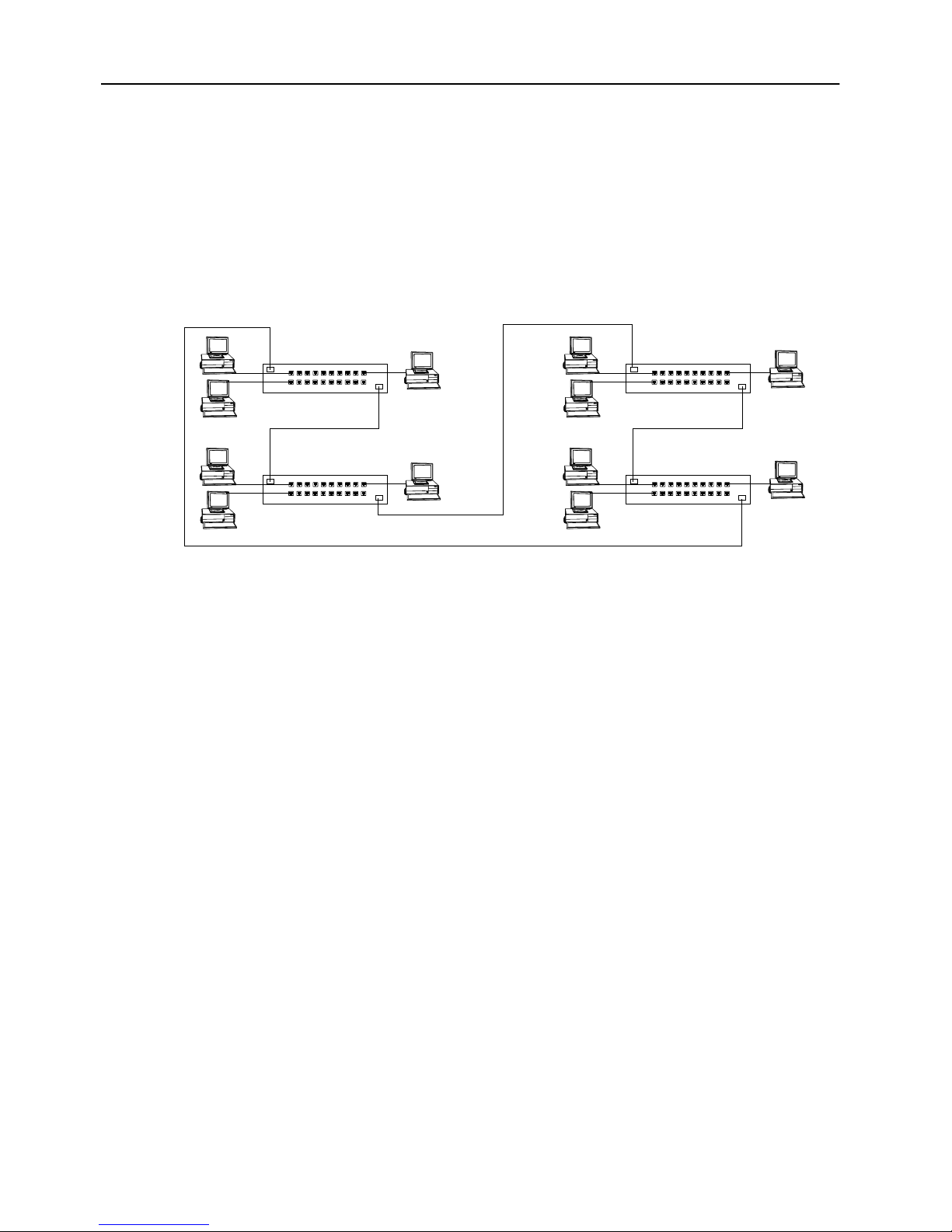
48
Sample Applications for the STS16-20RM and
the STS16-20FRM
The STS16-20RM and the STS16-20FRM switch allow you to make incremental
changes in your network to address both immediate and long-range performance
challenges. For example, a Token Ring LAN of 80 stations including 4 servers
might experience performance problems as a result of increased traffic. As it is
currently structured, the LAN looks like the one in Figure 12.
MAU
19 Workstations
MAU MAU
19 Workstations
Figure 12. Typical LAN Segmentation
Server
Server
MAU
19 Workstations
19 Workstations
Server
Server
All of the stations are attached to access units located in a single wiring closet. You
can install an switch in the same wiring closet and divide the LAN into 4 segments
of 20 stations each. One access-unit port from each segment will be connected to a
port on the switch via a patch cable. Finally, the four servers are removed from the
access units to which they have been attached and their cables moved to four ports
on the switch (as depicted in Figure 13).
Each group of 19 users attached to an access unit now shares a dedicated, 16 Mbps
path to the server. Each server has a dedicated, 16 Mbps path upon which to service
requests. The overall capacity of this solution is 64 Mbps; network capacity has
increased fourfold.
SmartStack STS16-20RM/STS16-20FRM Token Ring Switches, P/N: 9032957-01 Preparing for Installation
Page 63
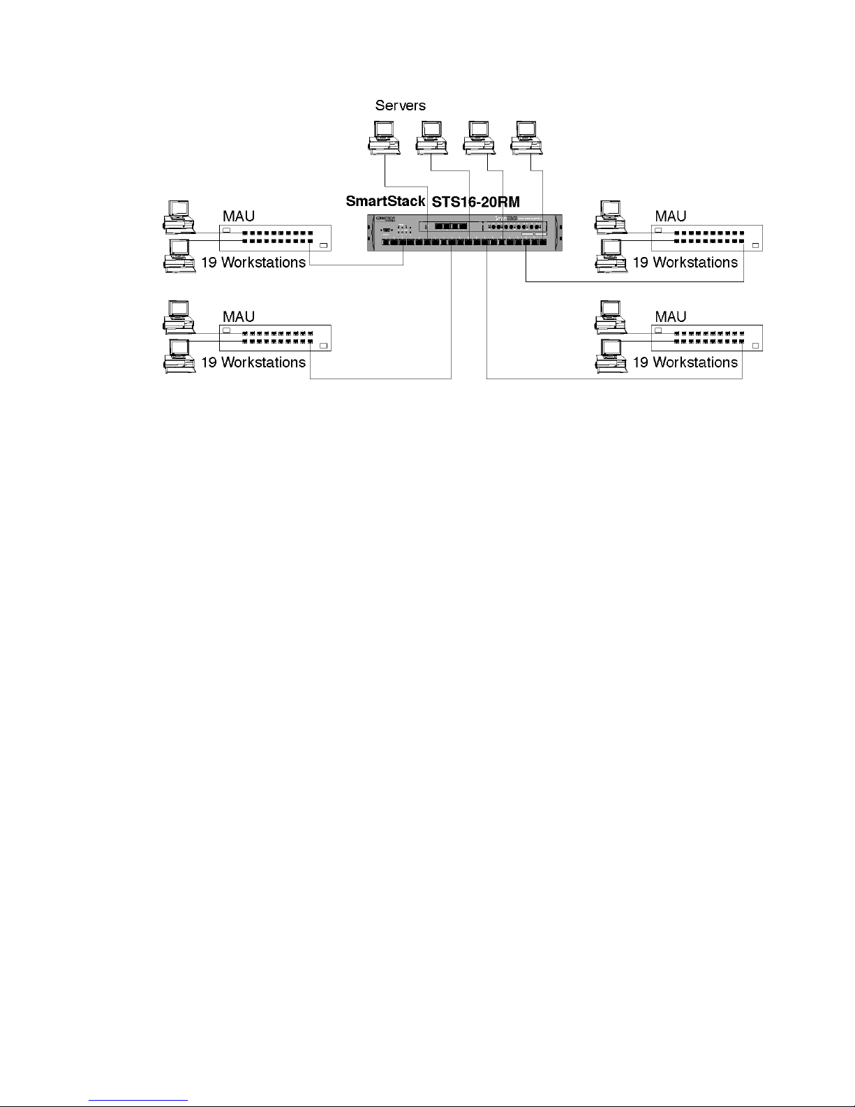
Figure 13. A Simple Application of the Switch
49
Some large, multisegment, hierarchical Token Ring networks experience
congestion at the campus backbone level. Although this congestion can often be
relieved by converting the backbone to a higher speed, shared-media protocol or by
installing additional bridges or dual backbones to eliminate bottlenecks, the
STS16-20RM switch and the STS16-20FRM switch offer dedicated-media that
might be longer lived or more economical if you eventually need higher demand
applications.
Figure 14 on the next page illustrates a typical network without the STS16-20RM
or the STS16-20FRM switch. This network is a three-level, hierarchical, campus
network. Figure 15 and Figure 16 offer several alternatives for using
the STS16-20RM or the STS16-20FRM switch.
Preparing for Installation SmartStack STS16-20RM/STS16-20FRM Token Ring Switches, P/N: 9032957-01
Page 64
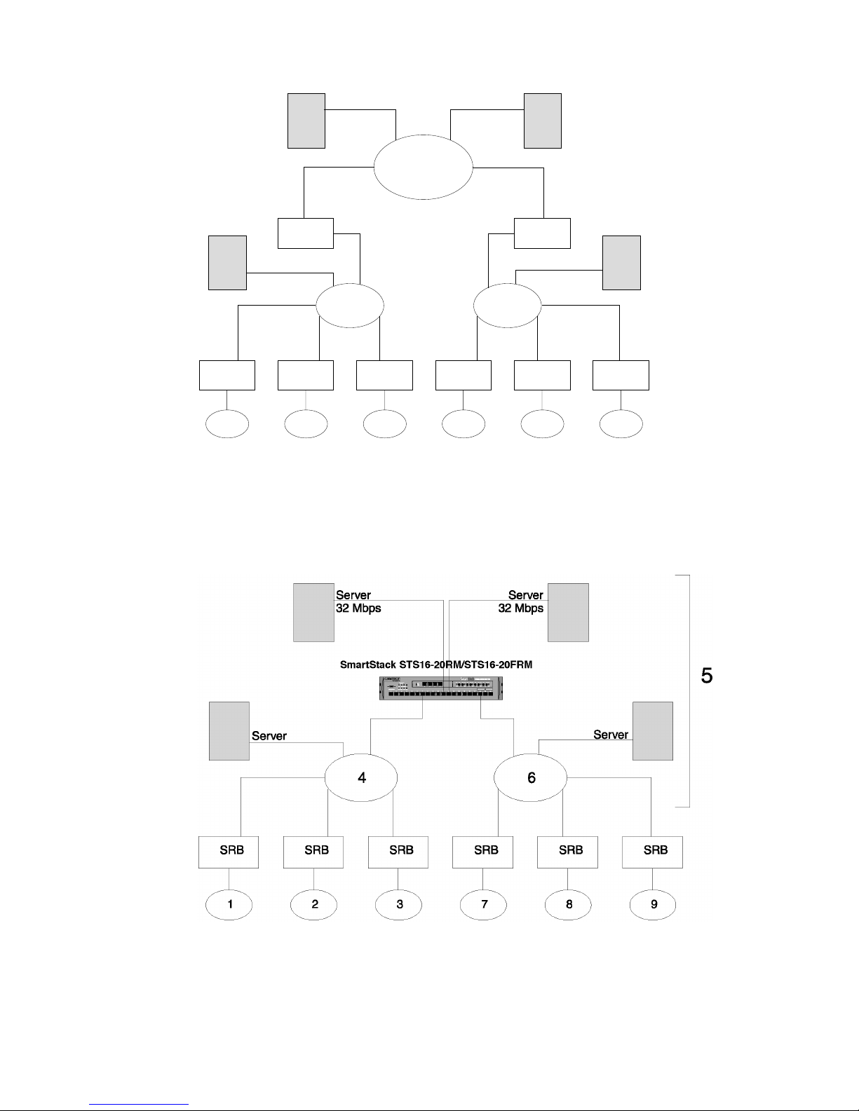
50
Server
Server
5
SRB SRB
SRB
8
Server
SRB
9
Server
4 6
SRB
1
SRB
2
SRB
3
SRB
7
Figure 14. Typical Network without the SmartStack Switches
In Figure 15, the congested campus backbone and the sourcerouting bridges
(SRBs) attached to it have been replaced by an STS16-20RM or an STS16-20FRM.
Figure 15. Relieving the Overstressed Backbone
SmartStack STS16-20RM/STS16-20FRM Token Ring Switches, P/N: 9032957-01 Preparing for Installation
Page 65
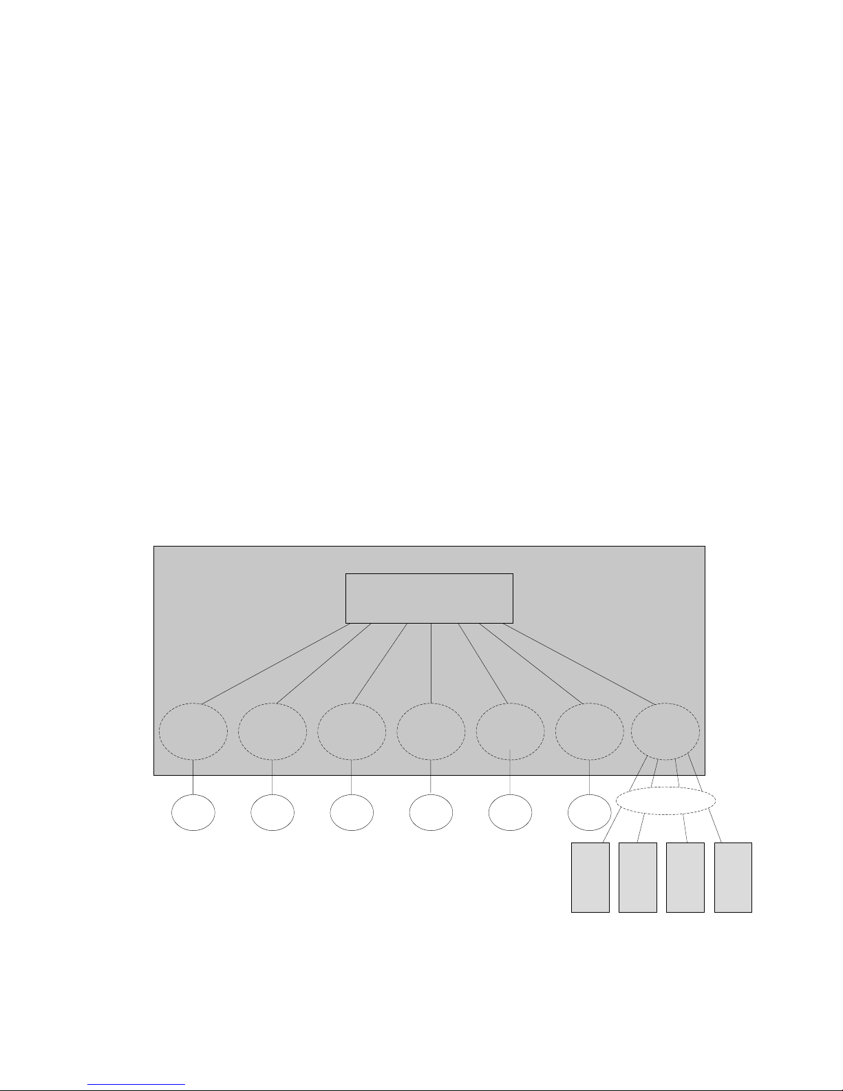
51
The Next Step
Typically, the first point of congestion in this newly configured network would be
the servers. Because the usual mode of operation for a Token Ring adapter is halfduplex, the servers can either send or receive information with one other segment
attached to the switch. If the server adapters are replaced with full-duplex adapters,
and are attached as single-station segments as shown in Figure 15, they can send
and receive data simultaneously. The capacity of each server is now 32 Mbps per
port.
However, network congestion is not always at the backbone level. In Figure 16, the
two MAUs and six bridges have been replaced by a single switch. Internally, the
switch is configured with one BRF and seven CRFs, allowing the switch to replace
the MAUs and bridges without the need for further reconfiguration. This
configuration greatly improves performance by allowing switching directly from
ring to ring. The four servers, each with a full-duplex connection to the switch, have
been grouped in CRF 5.
If even better performance is needed, the switch shown in Figure 16 can be replaced
with a stack of switches. A stack can provide up to 224 ports, making it feasIble to
connect workstations directly to a switch port. A direct connection provides a
dedicated 32 Mbps for users with high bandwidth requirements.
Switch
BRF
CRF 1
1 2
CRF 2
CRF 3
3
CRF 7
7
CRF 8
8
CRF 9
9
CRF 5
32 Mbps
Figure 16. Replacing SRBs with STS16-20RM or STS16-20FRM
Preparing for Installation SmartStack STS16-20RM/STS16-20FRM Token Ring Switches, P/N: 9032957-01
Server
Server Server Server
Page 66
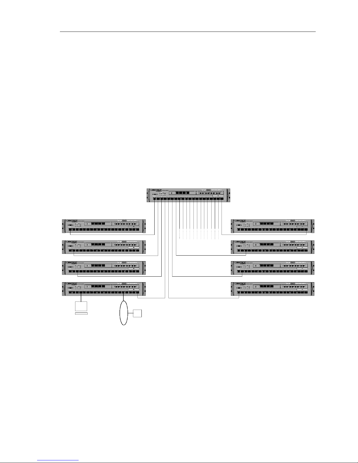
52
Important Management Considerations
A star-wired topology (see Figure 17) helps determine problems in a network
because no single cable carries all of the traffic on the network. However, serial
connections could reduce network reliability since each connecting cable and
switch could potentially divide the network should a failure occur.
If you create parallel paths directly between switches, be sure you have enabled
spanning tree protocol (the default setting for spanning tree protocol is no or
disabled). Parallel paths create endless loops that cause unsatisfactory network
operation unless you configure the switch for spanning tree capability. The
spanning tree algorithm disconnects loops in networks using the transparent
bridging algorithm or the SRT algorithm, and will block a port of one of the
switches in the parallel paths. If the port in the primary path fails, the port that has
been blocked will change automatically to the forwarding state, keeping the
network operational.
Figure 17. Star-Wired Topology of Interconnected Switches
SmartStack STS16-20RM/STS16-20FRM Token Ring Switches, P/N: 9032957-01 Preparing for Installation
❏
Page 67

4. Installation
This chapter contains step-by-step instructions for installing, connecting and
verifying that the STS16-20RM and/or STS16-20FRM Token Ring switch is
operating properly.
Installation Summary
The installation sequence is listed in the following steps.
1. Plan for installation. Read Chapter 3, “Preparing for Installation”.
2. Unpack the switch.
3. Gather the materials.
4. If you will be installing expansion modules, install them now.
53
5. Mount the switch.
6. Connect the switch to the network.
7. Verify the operation of the switch.
➽ Note:
configuration of the switch or monitoring its activity.
8. Configure the switch.
➽ Note:
LEDs, please see “Front Panel Details” on page 5 and “Back Panel Details” on
page 10 in Chapter 1.
Complete the following step only if you will be customizing the
For information on front panel and back panel connectors, buttons, slots, and
Installation SmartStack STS16-20RM/STS16-20FRM Token Ring Switches, P/N: 9032957-01
Page 68

54
P ackage Contents
Immediately after receiving the equipment, examine all shipping containers and
contents for damage. If any damage has occurred, notify the shipping carrier.
Unpack the unit by removing the packing material and lifting it from its protective
enclosures. Visually examine the equipment and check the container for related
parts and accessories. You should have the following items:
One STS16-20RM Token Ring Switch
•
OR
One STS16-20FRM Token Ring Switch
One CD-ROM containing the Token-Ring switch software and the SmartStack
•
Manager for Windows, as well as user documentation in PDF format
One SmartStack Manager for Windows Installation and User Guide
•
One printed STS16-20RM/STS16-20FRM Token Ring Switches Installation
•
and User Guide (this guide)
•
•
Report any missing parts and any damage, not related to shipping, to your customer
service representative.
➽ Note:
warranty should be shipped in their original packing materials.
If you have received your equipment before your site is fully prepared, after
inspection, you should keep all of the components in the original shipping
containers and store them in a physically and environmentally safe place.
One serial cable for the management port
One plastic bag containing four adhesive rubber feet and rack mounting
screws, an Allen key, nuts and washers
Keep the packing materials for future use.
All components returned under
SmartStack STS16-20RM/STS16-20FRM Token Ring Switches, P/N: 9032957-01 Installation
Page 69

Materials Needed for Installation
To install the switch, you need the following items:
If the unit will be installed in a rack, you need:
•
— A rack inventory chart and a cabling chart from your network
administrator.
— The supplied set of screws, nuts and washers along with the Allen key tool.
— A properly earthed power cord.
If the unit will be installed on a surface (such as a tabletop), you will need:
•
— A cabling chart from your network administrator.
— The four supplied adhesive rubber feet.
— A properly earthed power cord.
55
Installing a SmartStack Interface Module
Follow these steps to install a SmartStack Interface Module (SSIM), if you have
received one. Also, see the user documentation supplied with the module.
1. If you have not already done so, unplug or remove power from the switch.
2. Remove the SSIM from its box.
3. Remove the plate covering the SSIM slot on the front of the switch by loosening
the two thumbscrews holding it in place. See Figure 18. Use a screwdriver if the
screws are too tight to be removed with your fingers. Retain the plate and
thumbscrews for use in the event that the SSIM is ever removed.
4. Insert the card in the SSIM slot carefully, fitting each side into the card rails, and
making sure that the connector on the card is seated in the connector at the back
of the slot.
5. Secure the card with the two thumbscrews attached to it. This is illustrated in
the publication that was shipped with the SSIM.
6. It may be necessary to download new microcode to the switch in order to use a
specific SSIM. Refer to the instructions that came with your SSIM package.
Installation SmartStack STS16-20RM/STS16-20FRM Token Ring Switches, P/N: 9032957-01
Page 70
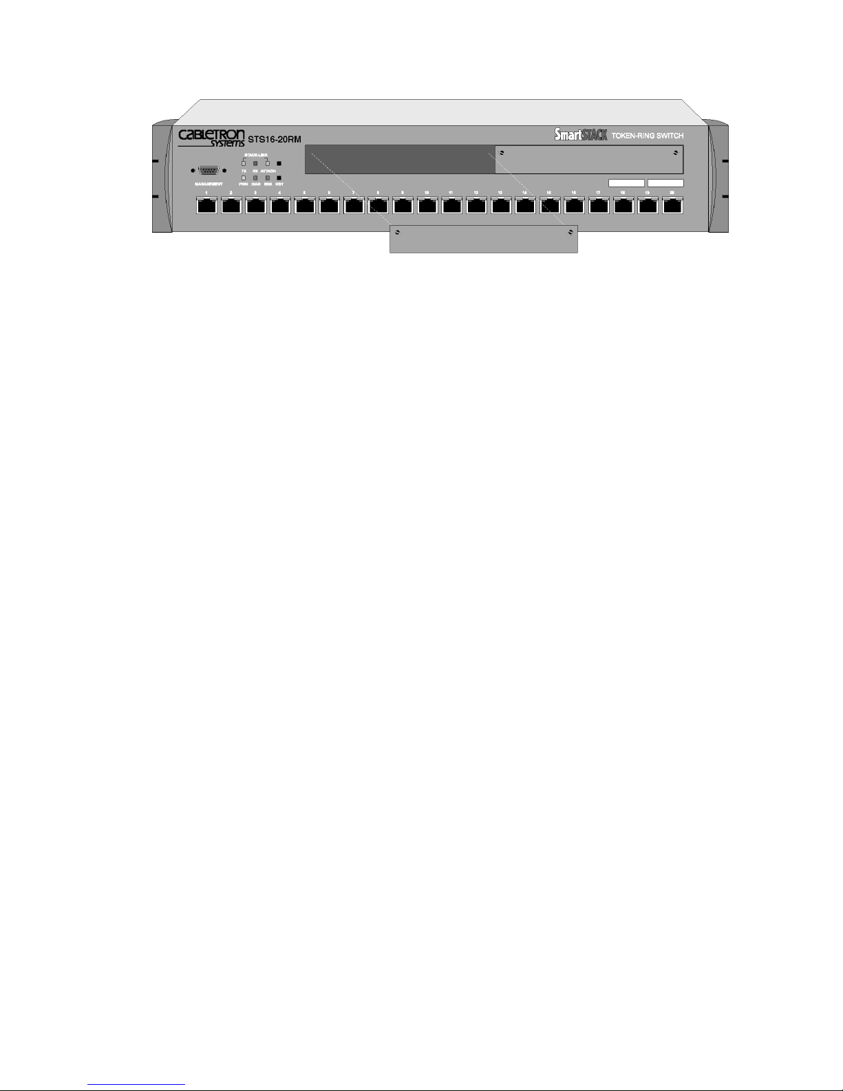
56
Figure 18. Removing the SSIM Slot Cover
SmartStack STS16-20RM/STS16-20FRM Token Ring Switches, P/N: 9032957-01 Installation
Page 71
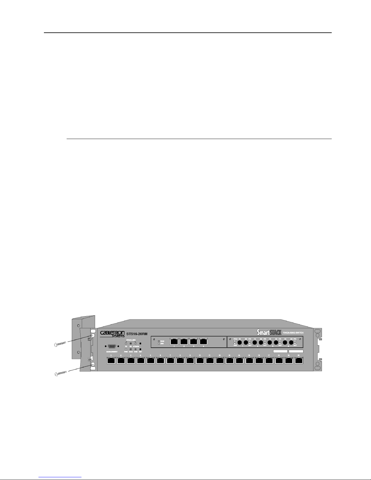
Mounting the Chassis
The switch can be mounted in a standard 19-inch rack or cabinet, or can be mounted
on any flat surface such as a tabletop. The installation area should be near a power
source and should have enough room around the front and back panels for cabling
and access to controls. Use the following procedures for the installation of the
switch.
57
➽ Warning:
replace this equipment.
Rack or Cabinet Mounting
If you install the equipment in a closed or multi-unit rack, observe the
environmental guidelines from the previous chapter, Chapter 3, “Preparing for
Installation”.
➽ Caution:
that the switch and any other equipment are mechanically stable.
The following steps describe how to mount the switch in a rack or cabinet:
1. Remove the bracket covers on each side of the switch to expose the rack
mounting brackets. Access to the retaining screws is obtained by opening the
cap on the front of each bracket cover. Use the Allen key supplied with the
switch to remove the two 6 mm Allen screws. When you have removed the
screws, push the bracket cover towards the back of the switch and lift the cover
off. Keep the screws for later use.
Only trained and qualified personnel should be allowed to install or
The following rack mounting instructions need to be observed to ensure
Figure 19. Exposing the Rack Mounting Bracket
Before going on to the next step, be sure you have the proper hardware for
mounting the chassis with the exposed brackets to your cabinet or rack.
Installation SmartStack STS16-20RM/STS16-20FRM Token Ring Switches, P/N: 9032957-01
Page 72
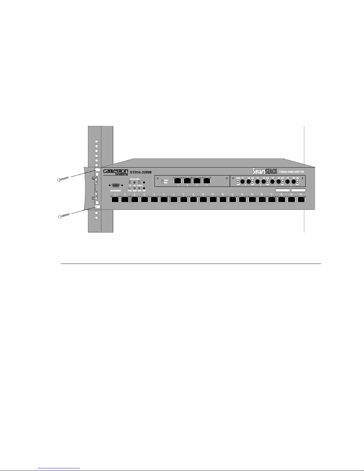
58
2. Position the switch, with the exposed mounting brackets, in the rack or cabinet
and slide it up or down until the bracket holes line up with the rack holes. Attach
the chassis brackets to the rack using the Allen screws you removed in the
previous step and the nuts supplied with the switch. Close the cap again to
conceal the screws.
➽ Note:
sliding pullout mount, you will need to provide the extra mounting hardware.
Figure 20. Mounting the Switch in a Rack or Cabinet
Only fixed brackets are supplied with these units. If you want to install a
Table-Mounting
The switch operates at a low noise level, which makes it suitable for a large enough
flat surface, such as a table.
Four self-adhesive pads are supplied with the switch. The pads must be mounted in
the four recesses on the bottom of the switch. When the pads are mounted, simply
place the switch on a clear, level location. Leave enough room around the switch
for ventilation and access to the controls and cable connectors.
➽ Caution:
equivalent weight of other equipment) directly on top of another chassis. More than
three units on top of another unit may cause damage to the lower unit.
Due to weight constraints, place no more than three units (or the
SmartStack STS16-20RM/STS16-20FRM Token Ring Switches, P/N: 9032957-01 Installation
Page 73

Cabling
59
➽ Note:
Panel Details” on page 5 and “Back Panel Details” on page 10 in Chapter 1.
This section provides instructions for connecting devices (such as hubs, servers,
personal computers, and workstations) to the switch. Remember these tips when
connecting cables:
•
•
•
•
•
For information on connectors, buttons, slots, and LEDs, please see “Front
Avoid stretching or bending the cables excessively.
Avoid routing the cables near potential sources of electromagnetic
interference, such as motorized devices and fluorescent lights.
Avoid trip hazards by routing the cables away from aisles and other areas
where people walk. If such routes cannot be avoided, use floor cable covers or
similar material to secure and protect the cables.
Be sure that the cables connected to the switch are supported so that the cable
connectors are not excessively strained.
On the STS16-20RM, use a Category 3 or better UTP cable or a 150 ohm STP
or STP-A cable with an impedance-matching balun at each end.
STS16-20FRM supports 50/125 µm and 62.5/125 µm fiber cables with a
•
VF-45 connector. Fiber cable lengths up to 2000 meters are supported.
Note that these connectors are not compatible to the fiber ST Duplex
connectors on the STS-T8-04 Token-Ring SmartStack Interface Module.
Standard converter cables are needed. Also, on STS16-20FRM, a UTP/STP
connection is only supported via the STS-T5-04 Token Ring SmartStack
Interface Module.
See Appendix B, “Cable and Pin Information” for specific information on
supported cable types, cable lengths and connector pinouts.
Connecting Devices to the Token Ring Ports
If you will not be using building wiring (in-the-wall cables) to connect the device
to the switch, perform the following steps. If you will be using building wiring,
follow the steps beginning with step 1 on page 60.
Follow these steps to connect one or more devices to the Token Ring ports on the
switch:
1. If you have an SSIM, connect it using the instructions in the documentation
shipped with it and then return here.
Installation SmartStack STS16-20RM/STS16-20FRM Token Ring Switches, P/N: 9032957-01
Page 74
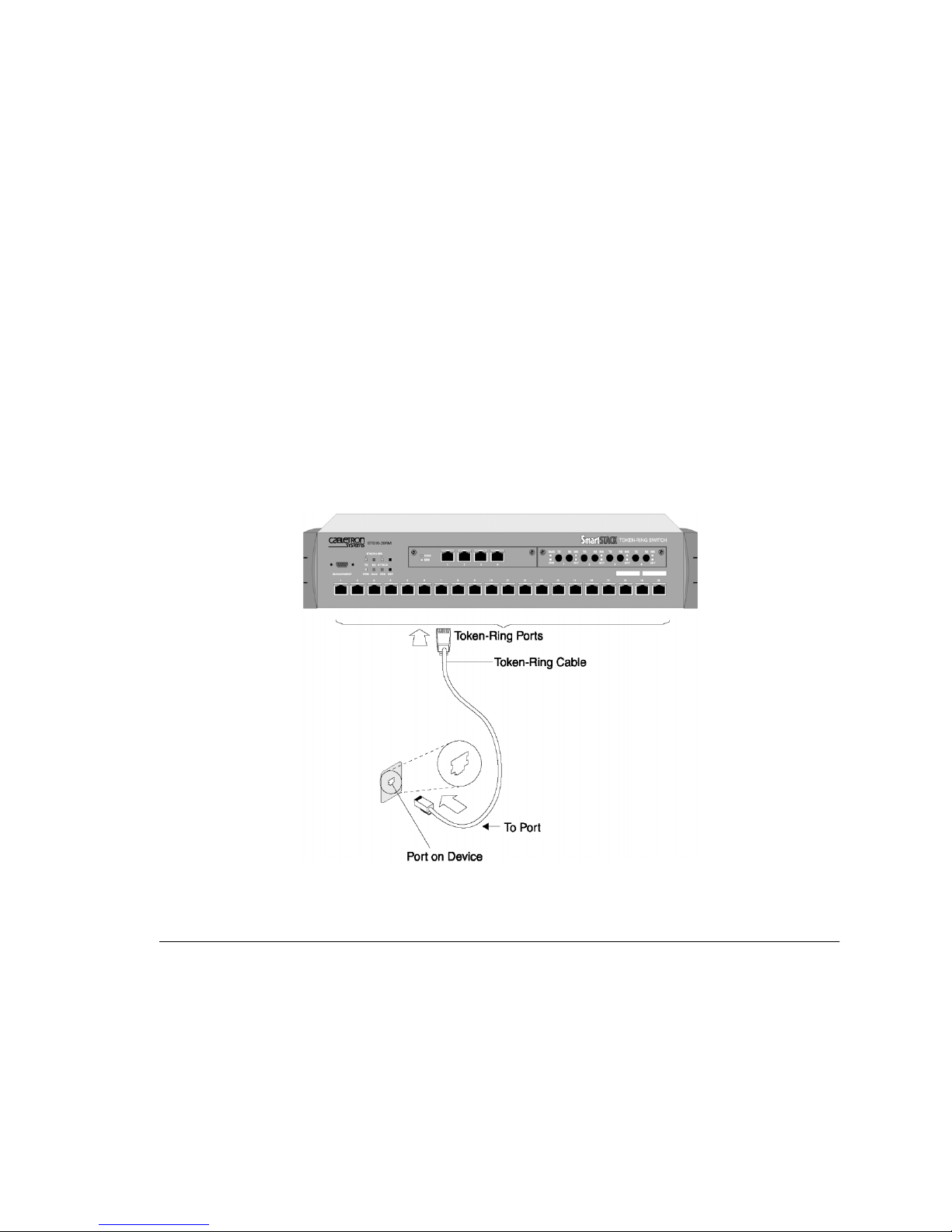
60
2. Using the switch Cabling Chart provided by your network administrator as a
guide, connect the cables between the switch and other devices as illustrated in
Figure 21. Note that the figure illustrates an RJ-45 connector on each end.
Depending on the cable type you use, the device end of the cable may also have
a 9-pin D-shell or 150 ohm Data Connector.
3. If the switch is rack-mounted, dress the switch end of the cables through a cable
management bracket, if one is present on your rack.
4. Label each end of the cables so that it will be easy to find the device if you have
to troubleshoot a network problem.
Suggested information to place on the label includes the room location of the
device at the other end, a unique cable identification number, the MAC address
of the connected device, and the number of the port to which the cable is
attached.
5. To continue installing the switch, go to “Applying Power” on page 62.
Figure 21. Connecting Devices to Token Ring Ports
Connecting Devices to the Token Ring Ports
Using Building Wiring
If you will use building wiring (in-the-wall cables) to connect the device to the
switch, perform the following steps:
1. If you have an SSIM, connect it using the instructions in the documentation
shipped with it and then return here.
SmartStack STS16-20RM/STS16-20FRM Token Ring Switches, P/N: 9032957-01 Installation
Page 75
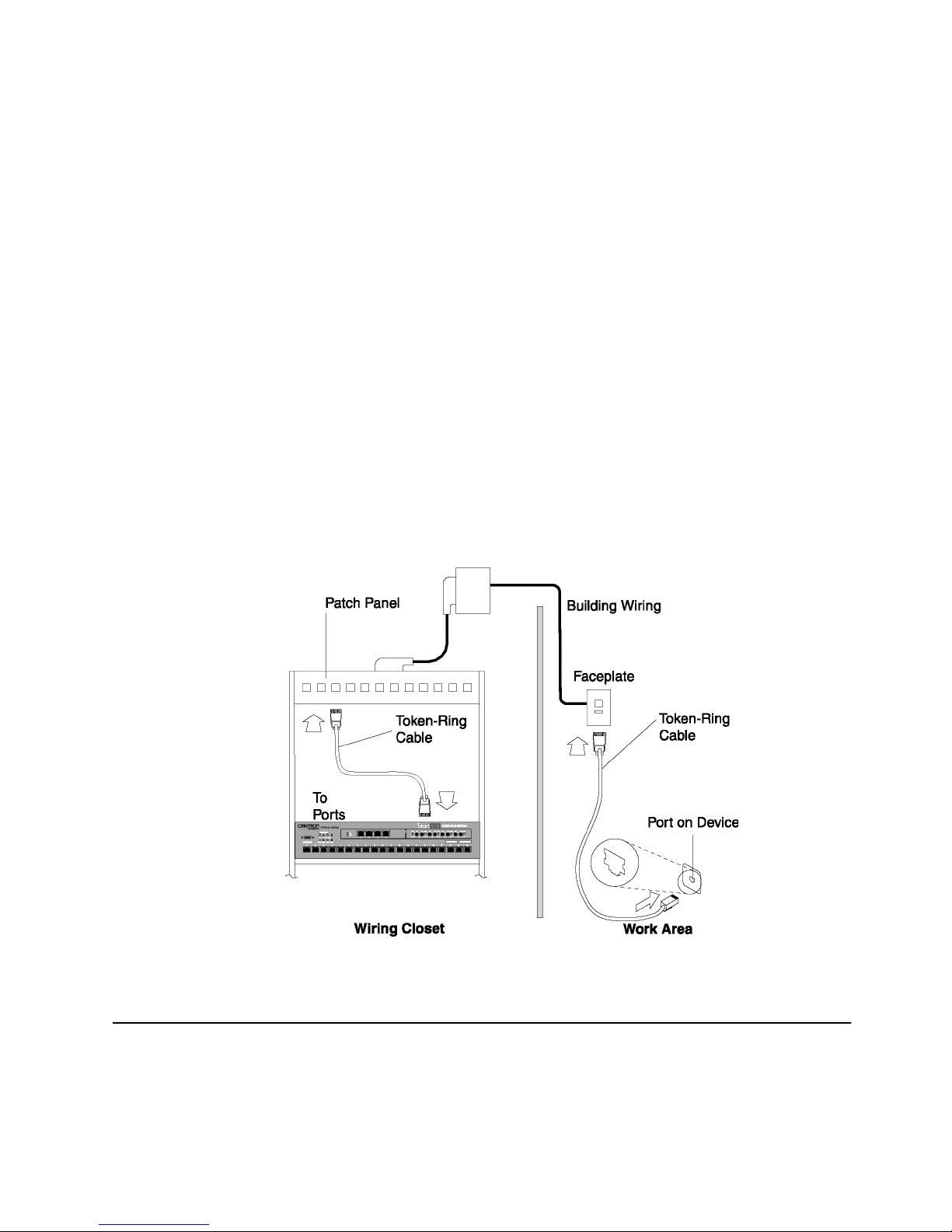
61
2. Using the Switch Cabling Chart provided by your administrator as a guide,
connect the cables between the devices and the faceplates as illustrated in Figure
22.
3. Label the faceplate, so that it will be easier to find the device if you have to
troubleshoot a network problem.
4. In the wiring closet, connect a cable to the Token Ring connector on the patch
panel or other equipment where the building wiring terminates.
➽ Note:
port on a media access unit (MAU) unless you use port 19 or 20 on the switch.
5. Connect the other end of the cable to a Token Ring port on the switch.
6. Label this cable.
7. If the switch is rack-mounted, dress the switch end of the cables through a cable
management bracket, if one is present on your rack.
8. To continue installing the switch, continue with “Applying Power”.
On STS16-20RM, do not connect these cables to the Ring-In or Ring-Out
Figure 22. Connecting using Building Wiring
Checking the Installation
Before you apply power to the switch, inspect the installation thoroughly. Verify
that all cables are installed correctly. Check cable routing, so a cable will not be
damaged or create a safety hazard. Be sure all equipment is mounted properly and
securely.
Installation SmartStack STS16-20RM/STS16-20FRM Token Ring Switches, P/N: 9032957-01
Page 76
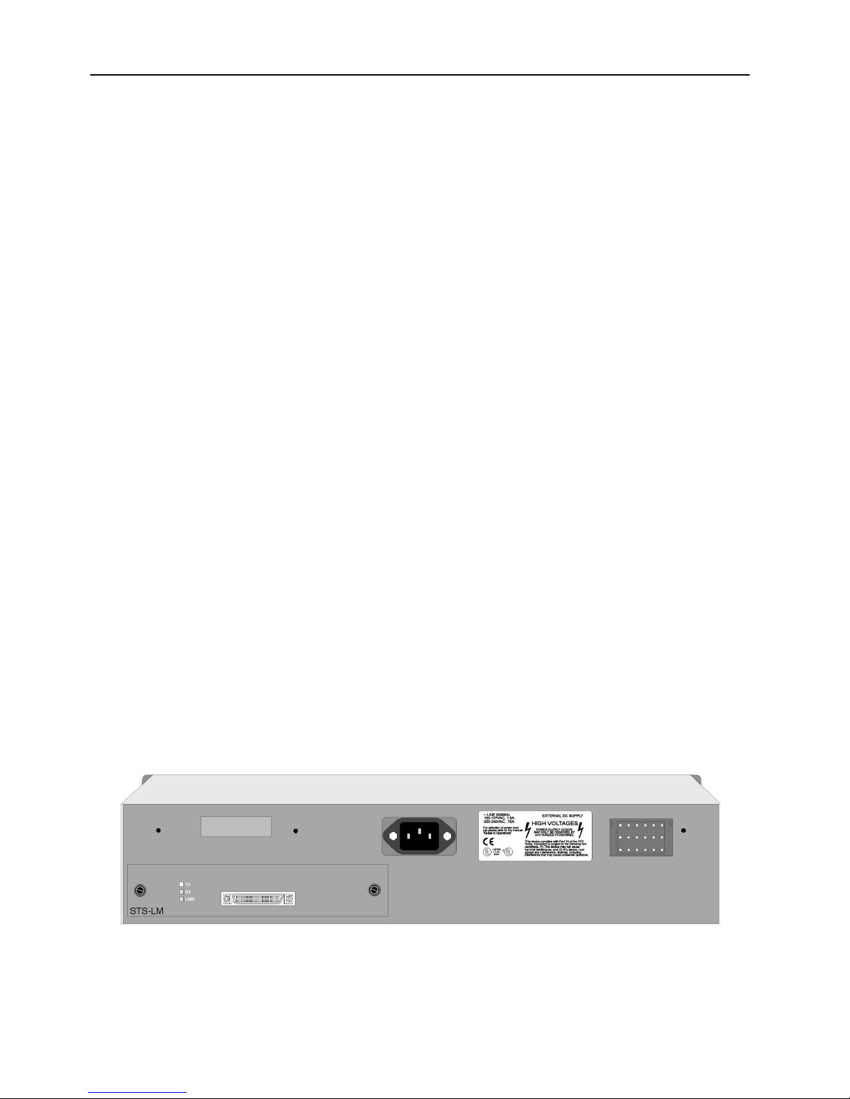
62
Applying Power
The switch chassis does not have an on/off switch.
plugged into a power source
There are no user serviceable parts inside a switch. Any internal upgrades or service
should be performed by Qualified Personnel
➽ Caution
note that this unit is
unit and the switch before connecting or disconnecting the DC power cable.
➽ Warning:
an on/off switch.
➽ Warning:
first and disconnected last.
➽ Warning:
connected to earth ground during normal use.
Power is on when the unit is
.
.
only
: If you are using the SmartStack STS-PSU redundant power supply unit,
hot-swappable. You must
not
turn off
the SmartStack STS-PSU
Unplug the power cord before you work on a system that does not have
When installing the unit, the ground connection must always be made
This equipment is intended to be grounded. Ensure that the host is
Use the following steps to power on your equipment.
1. Ensure that you are using the correct power source.
2. Using a power cable that complies with national regulations, plug the female
end of the cable into the AC power connector on the back panel of the switch
(see Figure 23).
3. Plug the male end of the power cord(s) into a properly grounded electrical
outlet.
Figure 23. The Back Panel of the Switch
SmartStack STS16-20RM/STS16-20FRM Token Ring Switches, P/N: 9032957-01 Installation
Page 77

63
4. Verify that the power LED is on. If not, make sure the outlet is working properly.
If the outlet is working, but the power LED and the fans are not on, see Chapter
10, “Troubleshooting”.
5. When the switch powers on, observe the self-test diagnostic that the unit runs
for approximately 1-2 minutes. The DIAG LED is on for the duration of the test,
turning off when the self-test is complete.
6. At the completion of the diagnostics, the front panel LEDs should be
illuminated according to the status of the unit’s configuration. See the following
sections for a description of the controls and LEDs for the switch.
➽ Note:
error, the ERR LED will be on or flashing on. If the ERR LED is on or flashes, see
Chapter 10, “Troubleshooting”.
If the switch fails to power up correctly or if it encounters any unrecoverable
❏
Installation SmartStack STS16-20RM/STS16-20FRM Token Ring Switches, P/N: 9032957-01
Page 78

64
SmartStack STS16-20RM/STS16-20FRM Token Ring Switches, P/N: 9032957-01 Installation
Page 79

5. Accessing Switch Management
The switches can be configured in two ways:
65
1.
Using the switch console
You can access the switch console interface
— directly, by connecting a VT100 terminal emulator to the RS-232 port
— remotely, via Telnet.
2.
Using SNMP based graphical management applications
— SmartStack Manager for Windows
— Other Simple Network Management Protocol (SNMP) based applications.
Overview
This chapter only describes how to access the switch console via the
MANAGEMENT port. Refer to the section “Console/Telnet Sessions” on page 131
for information on configuring serial console and/or telnet console sessions.
.
labeled MANAGEMENT.
OR
:
Network management applications (in-band management) are beyond the scope of
this guide. However, note that to be able to manage the switch by the network
management application via SNMP, you will have to configure a few settings first
in the switch console. These are typically the IP Address, SNMP Community, and
Trap Receiver.
Accessing Switch Management SmartStack STS16-20RM/STS16-20FRM Token Ring Switches, P/N: 9032957-01
Page 80
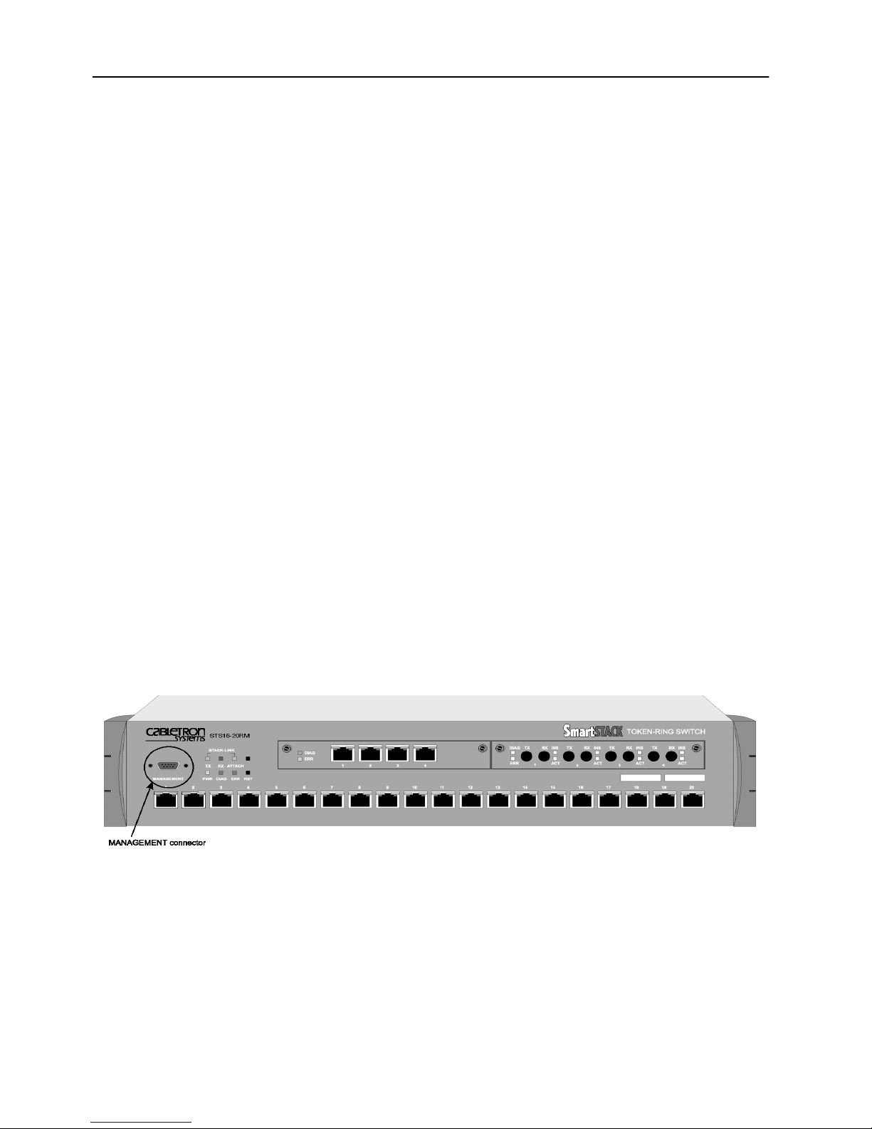
66
Connecting the Console
The two following subsections explain how to connect to the switch console. You
can connect directly or via a modem. For detailed information on cabling and pins,
see Chapter B, “Cable and Pin Information”.
Connecting a Terminal Directly to the MANAGEMENT Port
1. Connect one end of a crossover TIA/EIA-232 cable (commonly known as a RS232 cable) to the MANAGEMENT port. This is a male DB-9 connector
configured as a DTE (Data Terminal Equipment) device.
2. Connect the other end of the cable to a PC or another DTE device.
OR
1. Attach a null-modem adapter to the MANAGEMENT port.
2. Attach a straight-through modem cable to the null-modem adapter.
Connecting to the MANAGEMENT Port Using a Modem
1. Connect one end of a straight-through TIA/EIA-232 modem cable to the
MANAGEMENT port. This is a male DB-9 connector configured as a DTE
device.
2. Connect the other end of the cable to a modem.
See Figure 24 to view the location of the cable connection on the front panel of the
switch.
Figure 24. View of Console Connection—the MANAGEMENT port
The next step and table describe the settings to use for configuring a console in
order to communicate with the switch.
SmartStack STS16-20RM/STS16-20FRM Token Ring Switches, P/N: 9032957-01 Accessing Switch Management
Page 81

67
3. Use the values listed in the following table to set the configuration parameters
on your console for interfacing to the switch.
Specification Value
Baud Rate 2400, 4800, 9600, 19200, 38400, 57600
Parity None
Data bits 8
Stop bits 1
Handshaking None
Terminal emulation VT100
Duplex Full
Software flow control
Off (input and output)
(XON/XOFF)
Hardware flow
Off
control (RTS/CTS)
Autobaud upon break On
Line wrap On
Screen scroll On
CR translation CR
Backspace (BS)
Destructive
translation
Break length
350
(milliseconds)
Enquiry (ENQ) Off
EGA/VGA true
underline
Terminal width 8 0
ANSI 7 or 8 bit
commands
Table 10. Console Configuration Settings
Accessing Switch Management SmartStack STS16-20RM/STS16-20FRM Token Ring Switches, P/N: 9032957-01
Off
7
Page 82

68
Specification Value
Microsoft Windows
™ terminal
emulation
Table 10. Console Configuration Settings
Disable the
Ctrl Keys for Windows
Use Function, Arrow, and
option located in
the Terminal Preference menu
4. At power on (cold boot), the switch performs a series of self-test diagnostics
verifying that hardware components are functioning. An example of the self-test
diagnostic screen is shown later in this chapter.
Communication Problems
If the diagnostic list does not appear, or is garbled, try adjusting the baud rates
between the console and the switch by using the Autobaud routine within the
switch. To do this, press the reset button on the front of the switch and wait for the
internal diagnostics to finish (the DIAG LED turns off). The reason for the reset is
that in case the switch’s Autobaud routine is disabled, resetting it will set it to its
default mode of Autobaud enabled.
Depending on the type of the console, there are several console command keys that
will potentially initiate the Autobaud routine in the switch. Four of these keys are
RETURN
, the combination keys
ALT-B
, the
BREAK
key, and
ESC
.
After the DIAG LED turns off, try one of the command keys at the console, and
press it repeatedly. If there is no response, wait several seconds and again, press it
repeatedly. If necessary, perform the same routine using the other command keys.
If this does not work, and there is a garbled output on the screen, try pushing the
unlabeled system request button on the switch. As soon as garbled characters
appear, press the console’s
RETURN
key twice in rapid succession. (Again, try the
other command keys as necessary).
If the problem remains, try the following steps:
1. Check all of the cable connections.
2. Check the baud rate at the console’s set up screen; if it is not set to 9600, try this
setting.
3. Try setting the console baud rate to different values up or down, and pressing
RETURN
for each selection.
4. If you are using a terminal emulation program, try exiting the program and
restarting.
SmartStack STS16-20RM/STS16-20FRM Token Ring Switches, P/N: 9032957-01 Accessing Switch Management
Page 83

69
5. If you still can not get the connection to work, contact technical support as
described in Chapter 11, “Getting in Touch with Technical Support”.
Diagnostic Screen
The diagnostic self-test displays two different screens, depending on whether you
perform a cold boot (power-on cycle with full diagnostics), or a warm boot (a reset
without full diagnostics). The warm boot contains portions of the complete cold
boot list.
The following is an
example
of a diagnostic screen during a boot process. The
actual screen may vary depending on, for example, hardware, options, and software
version levels:
BootStrap Firmware v2.3, Copyright 1996-1998
- Initiating bootstrapping sequence.
- Boot image integrity check...Passed.
- Control transferred to boot process.
Boot Firmware (Phase II) v2.3
- Program memory test........Passed.
- Relocating main image to
DRAM.......................................Done.
- Main image integrity check...succeeded.
- Control transferred to main process.
- Starting Power On Self Test Diagnostics.
- Network memory test 32-bits........Passed.
- Network memory test 16-bits........Passed.
- Network memory test 8-bits........Passed.
- Port register and memory test.....................Passed.
- Single port loopback test.....................Passed.
- All ports linked loopback test.....................Passed.
- Port MAC test.....Passed.
- Completed Power On Self Test Diagnostics.
System Software Version 4.0.0, Copyright 1994-1999.
System started on Mon. June 21, 1999 14:30:03
8 Megabytes System memory
2 Megabytes Network memory
- Initialization started
- File system initialized
- System temperature is within safe operating levels
- Checking file system integrity
- Warmboot initialization started
- LAN ports detected:
- RJ-45 Token Ring: 1 2 3 4 5 6 7 8 9 10 11 12 13 14 15 16 17 18 19 20
- StkPort : 29
Accessing Switch Management SmartStack STS16-20RM/STS16-20FRM Token Ring Switches, P/N: 9032957-01
Page 84
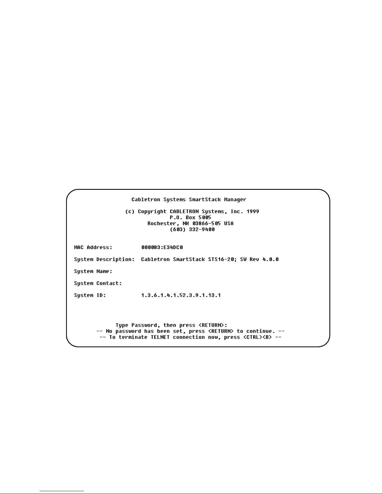
70
- Initializing Ports: 1 2 3 4 5 6 7 8 9 10 11 12 13 14 15 16 17 18 19
20 29
- Initializing system address table
- System entering stand-alone mode
- System initialization complete
- Enabling port: 1 2 3 4 5 6 7 8 9 10 11 12 13 14 15 16 17 18 19 20 29
Press RETURN key to activate console...
Depending upon which tests have run, verify that all diagnostics have passed and
that the ERR LED is off. If the ERR LED is on, read the screen to determine which
test failed. Also see Chapter 10, “Troubleshooting”, to help find the cause.
At the end of the boot messages, you should be prompted to press
RETURN (ENTER)
The following greeting screen of the switch console manager should appear:
.
At the top level screen, press
contents of the main menu, the submenus and screens are described in subsequent
chapters. The information in these chapters includes configuring, monitoring, and
viewing statistics on the switch.
➽ Note:
If you have forgotten the password, you can delete it by pressing the
unlabeled system request button on the front panel of the switch for one second.
Then release it and select
the
Read-Only
SmartStack STS16-20RM/STS16-20FRM Token Ring Switches, P/N: 9032957-01 Accessing Switch Management
and the
ENTER (RETURN
) to enter the main menu. The
Point 4. Clear the system password
Read/Write
password.
. This will clear both
❏
Page 85

6. Switch Configuration
This chapter explains how to set up the STS16-20RM or the STS16-20FRM Token
Ring switch and how to modify the configuration using a VT100 console attached
to the switch directly or via a modem connection. The switch configuration can also
be modified from a remote VT100 console via a telnet session.
For information on how to connect the console, see Chapter 5, “Accessing Switch
Management”.
Subjects covered in this chapter:
General guidelines (page 72)
•
Main menu screen (page 74)
•
Configuration menu (page 75)
•
Switch and stack configuration (page 76)
•
71
Module information (page 80)
•
Virtual LANs (page 82)
•
IP Configuration (page 91)
•
Spanning tree protocol (STP) (page 94)
•
Port configuration (page 104)
•
CrossLink channels (page 109)
•
Address filtering (page 115)
•
Address aging (page 125)
•
Console password (page 129)
•
Console/telnet sessions (page 131)
•
Syslog facility (page 138)
•
DSRR configuration (page 140)
•
Download/Upload menu (page 146)
•
Reset menu (page 151)
•
Switch Configuration SmartStack STS16-20RM/STS16-20FRM Token Ring Switches, P/N: 9032957-01
Page 86

72
General Guide l ine s
To work within the console menus and screens, follow these guidelines:
To select an item on a screen or a menu, highlight it by using the arrow keys
•
and then press
item—for example, selecting
appears on the screen.
ENTER
. If you need to specify additional information for that
or No or supplying a
Ye s
value
—a prompt
In most cases, new values are saved when you select
•
The
•
•
•
•
•
•
•
•
More
screen. Selecting
information.
Port
Index
To return to the main menu from any screen, press
changes made to the screen you were in will not be saved when you do this.
To return to the greeting screen, press
To refresh the console screen, press
If you are administering switches in a stack, many of the console screens will
prompt for a box number. Enter the number of the box you want to administer.
The “VLAN” term in connection with CRF is discussed on page 29.
The terms “Virtual LAN” and “domain” are interchangeable.
item means there is more information than what is displayed on that
More
refers to the number of a specific port on a switch.
refers to the numerical order of a list.
and pressing
ENTER
CTRL-B
CTRL-L
displays the next screen of
.
.
Return
CTRL-P
.
. Note that any
The console automatically returns to the greeting screen after five minutes of
•
inactivity. Five minutes is the default value. The time can be changed at the
Console Configuration
To open the
Configuration
For protection against inadvertent or unauthorized access to configuration
•
screens, you may establish a password that users must enter at the greeting
screen. In release 4.0 (and later) two types of users can be defined:
Read-only
These users cannot modify any of the configuration parameters.
They can read everything (except the SNMP communities).
Read-write
•
These users have full access to all configuration parameters.
Console Configuration
→→→→
users:
users:
menu as explained later in this chapter.
menu from the main menu, select
Console Configuration
.
SmartStack STS16-20RM/STS16-20FRM Token Ring Switches, P/N: 9032957-01 Switch Configuration
Page 87

73
If no password is configured, just press
To establish a password, see the section "Password Menu" on page 129 later in
this chapter. To open the
For more explanation on the greeting screen, see Chapter 5, “Accessing Switch
Management”.
Password
ENTER
menu, select
and the main menu is presented.
Configuration
→→→→
Password.
Navigating within the Menus
Use the arrow keys (also referred to as cursor keys) to highlight an item on the
screen or menu.
Items that end with three dots, opens another screen or menu. Pressing the
•
ENTER
If the item on the screen is a command, such as
•
will execute the command.
Unless specified differently, all the screens and menus are accessed in the same way.
The following section describes the items on the main menu.
key on such an item will display the new screen or menu.
Reset
, pressing the
ENTER
key
Switch Configuration SmartStack STS16-20RM/STS16-20FRM Token Ring Switches, P/N: 9032957-01
Page 88
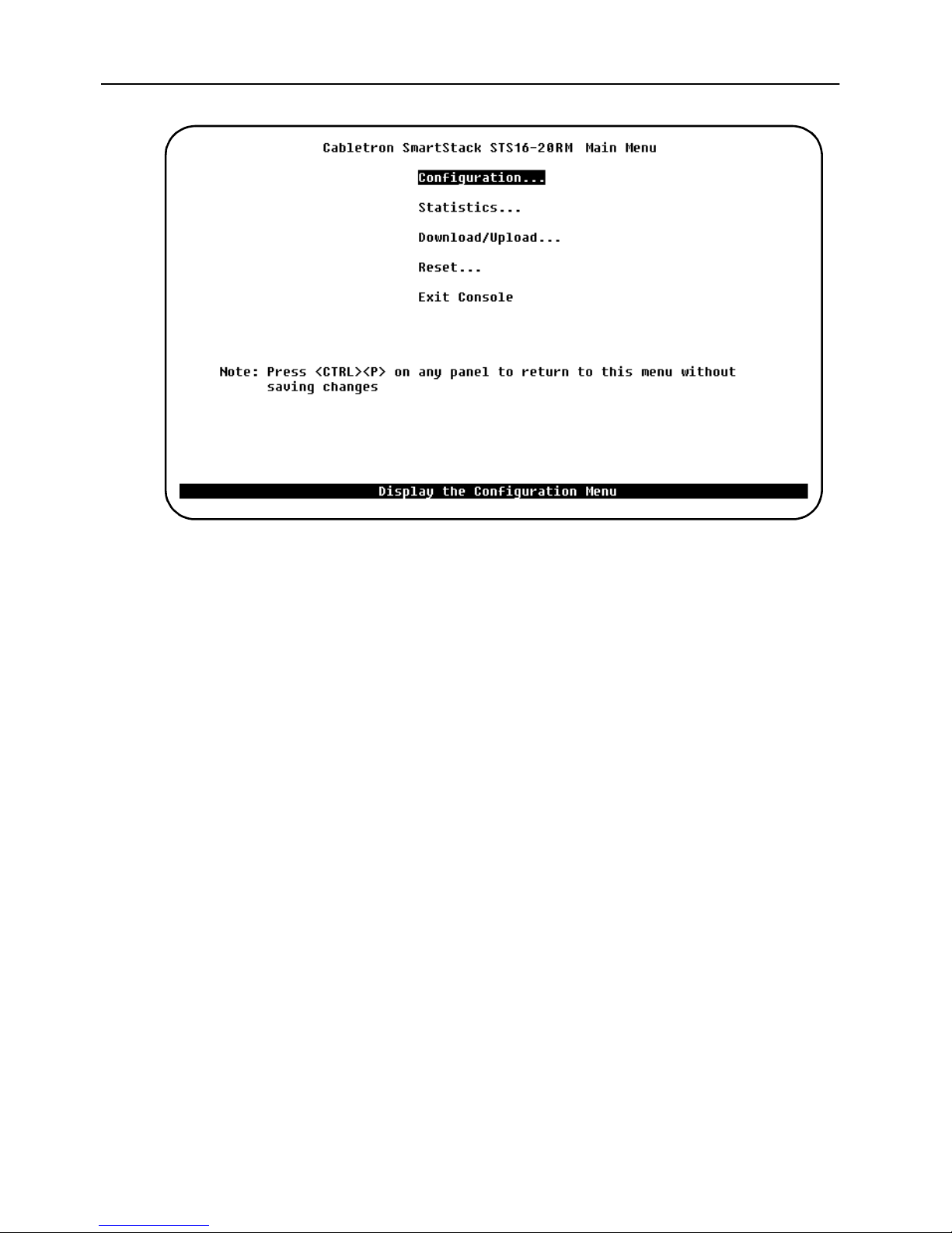
74
Main Menu
The main menu contains the following items, that give access to console screens
and submenus:
Configuration...
Displays the
Configuration
menu, which enables you to view and set the switch
configuration parameters. A detailed explanation of the configuration submenus is
given on page 75.
Statistics...
Displays the
Statistics
menu are in Chapter 7, “Monitoring the Network from the Console
Statistics
menu for the switch. Explanations of screens in the
Statistics Menu” on page 153.
Download/Upload...
Displays the
Download/Upload
menu that is explained in this chapter, starting
from page 146.
Reset...
Displays the
Reset
menu that is explained in this chapter starting from page 151.
Exit Console
Highlighting this command and pressing
greeting screen (on a Telnet session, this will cause the session to close).
SmartStack STS16-20RM/STS16-20FRM Token Ring Switches, P/N: 9032957-01 Switch Configuration
ENTER
will return the console to the
Page 89
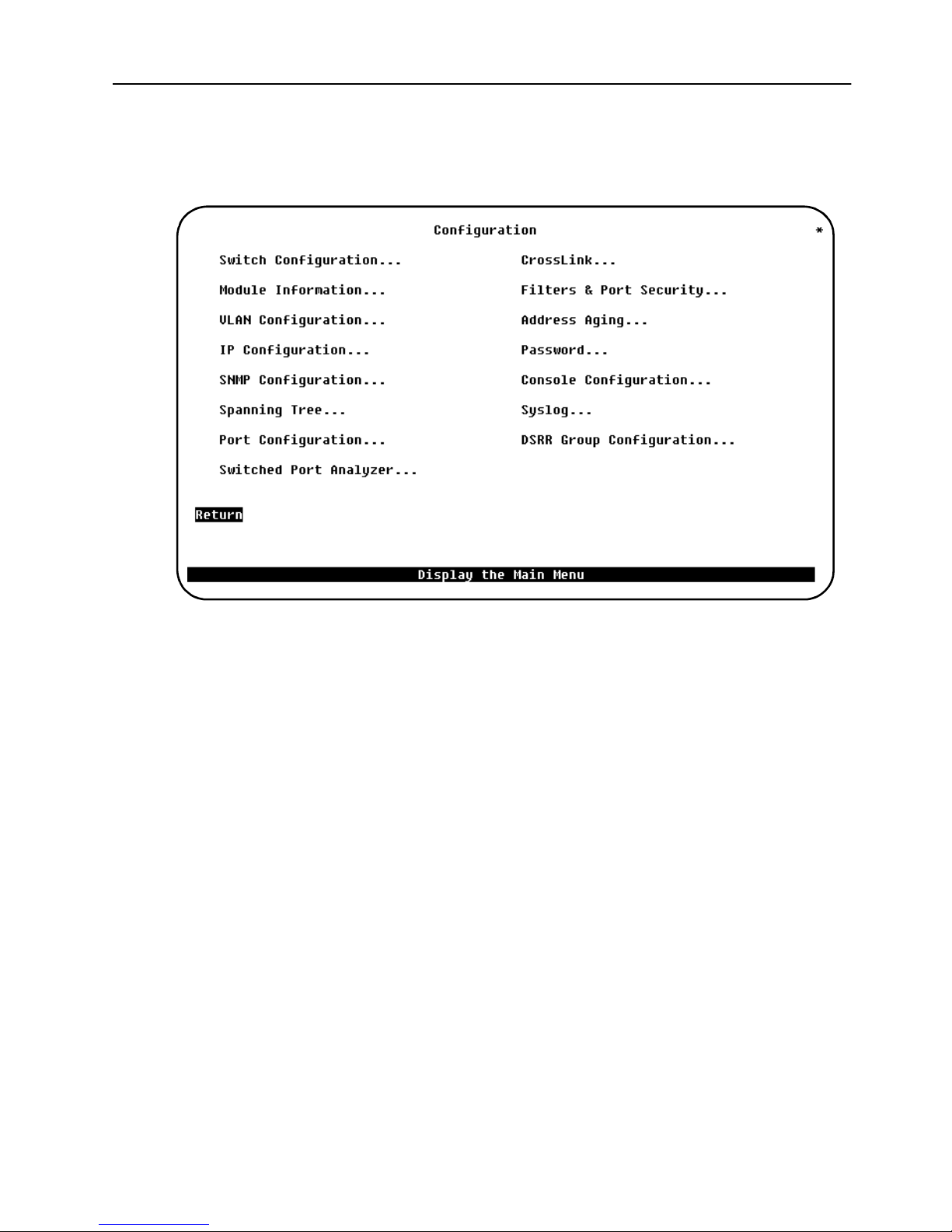
Configuration Menu
75
Open this menu by selecting
Configuration
menu you can view and set the switch configuration parameters.
Configuration
in the main menu. From the
This chapter describes all submenus and screens.
Switch Configuration SmartStack STS16-20RM/STS16-20FRM Token Ring Switches, P/N: 9032957-01
Page 90
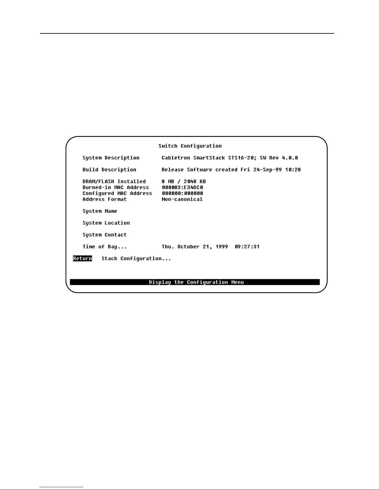
76
Switch Configuration Screen
To open this screen from the main menu, select
Configuration
Use the
change the system name, location, contact, and time of day. To add or change the
system name, location, contact or time of day, use the arrow keys to highlight the
field and press the
entering text for that field. Pressing
Switch Configuration
....
ENTER
screen to view system information and to view or
key. A prompt appears near the bottom of the screen for
ENTER
Configuration
again enters that text.
→
→
→ →
Switch
System Description
Name and model of the switch, or, in the case of a stack, the generic stack name. In
addition to this, the firmware release is displayed. Information in this field cannot
be changed.
Build Description
Describes when the firmware running in the switch was built. Display only.
DRAM Installed
Amount (in MB) of dynamic memory installed. Display only.
Flash Memory Installed
Amount (in KB) of flash memory installed. Display only.
Burned-in MAC Address
The factory-assigned base MAC address of the switch. Display only.
SmartStack STS16-20RM/STS16-20FRM Token Ring Switches, P/N: 9032957-01 Switch Configuration
Page 91

77
Configured MAC Address
The MAC address that is currently in use, or, if a new MAC address has been
configured, the MAC address that will be used after the next boot. If a locally
administered address is assigned to the switch, this field displays that address.
Otherwise, the field displays
address, select this field, and enter the new address. Note that the switch occupies
this address, the base MAC address, and possibly the next 96 addresses.
000000:000000
. To assign a locally administered
To configure a LAA address, use the
session or an SNMP based management tool. Note that a restart is necessary when
changing the base MAC address.
The greeting screen on the console will always show the current active Switch base
Address.
The switch reserves 31 addresses for ports.
The Token Ring ports on a switch will be assigned MAC addresses using the
following scheme:
BASE Module port 1- 20 Will be assigned Switch Base Address + port
•
LEFT SSIM port 1-4 Will be assigned Switch Base Address + 20 +
•
RIGHT SSIM port 1-4 Will be assigned Switch Base Address + 24 +
•
OR:
Switch Configuration
number
port number
port number
screen from a console
A Token Ring port will be assigned a MAC address, which is Switch Base Address
+ the port number displayed on the port configuration screen (or interface table for
SNMP).
This MAC address is used for the Token Ring MAC protocol, and for the spanning
tree protocol.
The switch reserves 63 addresses for BRF ( VLAN).
Each VLAN has an attached bridge relay function (BRF) and a management entity
(IP-protocol stack), and consequently it needs a MAC Address. In the switch, these
two logical units use the same address, however this address must be unique in the
network. This is ensured by assigning MAC address to BRFs from the Switch Base
Address + 32 (0x20) and upwards. The switch is designed in such a way, that it
operates with 63 active or preferred VLAN’s, implying that 63 MAC addresses
need to be reserved for BRF.
Switch Configuration SmartStack STS16-20RM/STS16-20FRM Token Ring Switches, P/N: 9032957-01
Page 92

78
Summarizing each switch reserve: Switch Base Address + 31 Addresses for Token
Ring ports + 63 MAC Addresses for BRFs = 95, which is rounded up to 96 or
hexadecimal 0x60.
The MAC address of the default BRF (trnet-default) will always be the switch base
address + 32. If the switch operates in a stack, only one of the switches will operate
the bridge relay function. Hence the MAC address of the default BRF will be based
on the address of the stackmaster. The stackmaster is determined by software, when
the stack consists of two switches back to back and by the port numbers in STS8SU/STS-5SU stack configurations.
There is no simple rule to find the default MAC address of other BRFs, but it is
always in the range as described in the following:
Stack Master Base Address + 32 < BRF MAC Address < Stack Master Base
Address + 95. And a BRF (VLAN) MAC address is assigned, when the VLAN
becomes preferred (that is, it has an assigned port in the actual switch or stack
of switches) by selecting the lowest available MAC address above Stack Master
Base Address + 32.
If management (SNMP or TELNET) contact with the switch is lost (because, for
example, ports are moved from one BRF to another) it is suggested, that a terminal
is connected to the OBM port of the switch stack, and the IP Configuration menu
is entered. From here, it is possible to read the MAC address of the management
entity (BRF).
In version 3.10.0 (and later) it is possible to assign an individual, locally
administrated MAC address to each VLAN.
➽ Note
"VLAN Configuration" on page 82.
Address Format
Display format used for MAC addresses (canonical or non-canonical). Canonical
format is typically used in Ethernet networks and is also known as least significant
bit first. Non-canonical is typically used in Token Ring networks and is also known
as most significant bit first.
System Name
! A reboot of the switch is necessary after assigning the VLAN LAA. See
Any name you choose to assign to the switch (on a TCP/IP network, it could be the
IP hostname).
System Location
Any text string of max. 64 characters that you have assigned for the switch.
SmartStack STS16-20RM/STS16-20FRM Token Ring Switches, P/N: 9032957-01 Switch Configuration
Page 93
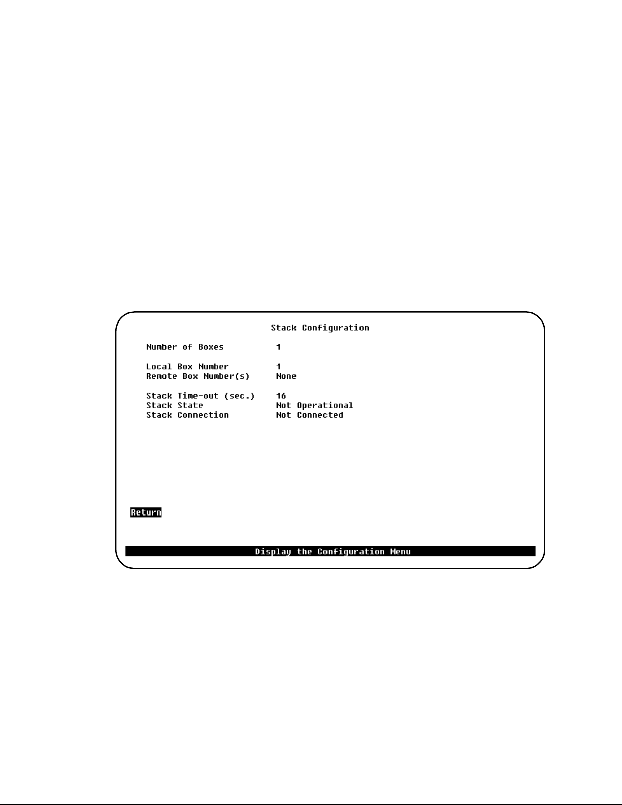
System Contact
Any text string of max. 64 characters you have assigned for the switch.
Time of Day
An internal clock is used to calculate total time of operation and time of day. To
adjust the time, select this item, press
minute.
ENTER
, then enter the month, day, hour, or
79
➽ Note:
this is the case, contact your local reseller.
Stack Configuration Screen
To open this screen from the main menu, select
Configuration
If you cannot set the
→
→
Stack Configuration
→ →
Time of Day
, the lithium battery may need replacing. If
→
→
Configuration
.
→ →
Switch
The following information is displayed on this screen:
Number of Boxes
Number of switches currently participating in the stack. Information in this field
cannot be changed.
Local Box Number
Number assigned to the currently selected switch. The local box is also the source
of the information displayed on this screen. Information in this field cannot be
changed.
Switch Configuration SmartStack STS16-20RM/STS16-20FRM Token Ring Switches, P/N: 9032957-01
Page 94
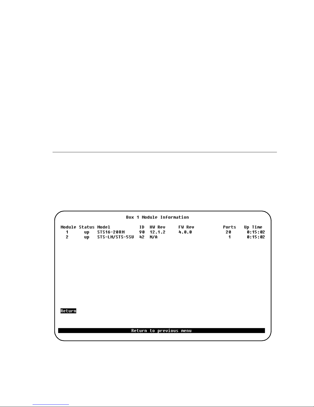
80
Remote Box Number(s)
Number of switches (in addition to this one) in the stack. Information in this field
cannot be changed.
Stack Time-out
If a switch goes off line, the length of time (in seconds) during which the stack tries
to reestablish communication with the switch. The default is 16 seconds.
Stack State
Whether the SmartStack Switch Stacker is operational (SmartStack STS-LM or
SmartStack STS-5SU). Display only.
Stack Connection
Whether the STS-8SU SmartStack Stacker Unit is connected. Display only.
Module Information Screen
To open this screen from the main menu, select
Information
If expansion modules have been installed, this menu provides information on them.
The switch is listed as the first module.
....
Configuration
→
→
→ →
Module
The following information is displayed on this screen:
SmartStack STS16-20RM/STS16-20FRM Token Ring Switches, P/N: 9032957-01 Switch Configuration
Page 95

Module
Module number. The switch is listed as module 1. Expansion cards are listed as
module 2 and module 3. The stack port is listed as module 4.
Status
Whether the module is up, down, failed, or the slot is empty.
Model
Type of module. The SmartStack switch is listed for the base switch. For this
module as well as for others, this field displays the product number.
ID
Decimal identifier of the module.
HW Rev
81
Hardware revision level. If
(4K)
is displayed after the number, this uplink will
prevent the switch (or stack of switches) from operating with an MTU size above
4,472 bytes. If
HW Rev
is set to NA, the module does not support reading of the
hardware revision..
FW Rev
Firmware revision level.
Ports
Number of ports on the module.
Up Time
Amount of time that the module has been up (since the last reset). Display only.
Switch Configuration SmartStack STS16-20RM/STS16-20FRM Token Ring Switches, P/N: 9032957-01
Page 96
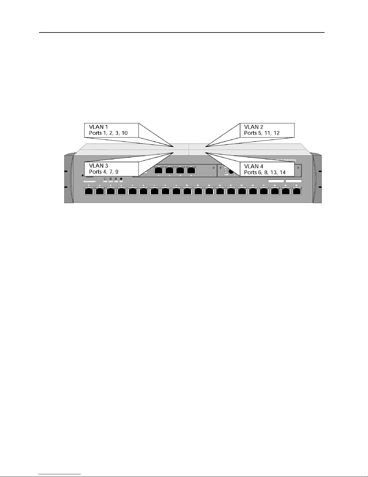
82
VLAN Configuration
The Virtual LAN feature can be used to partition a switch or a stack of switches into
several Virtual LANs, each containing its own set of ports (the terms
and
domain
belonging to the same VLAN. The benefit of Virtual LAN is to restrict access from
one segment to another, either for security purposes or to reduce intersegment
traffic. Figure 25 illustrates a switch with four VLANs.
are interchangeable). Packets are forwarded only between ports
Virtual LAN
Figure 25. Switch with Four VLANs
To set up domains using the VLAN Configuration menu, specify the ports
belonging to the domains, then set up the IP configurations, trap configuration (trap
receivers are associated with a set of VLANs and a receiver IP address) and STP
configurations specific to the appropriate VLANs. If you have already supplied
configuration information using the main configuration menus, that information
applies to VLAN “default”. Virtual LANs affects other switch features in the
following ways:
Spanning tree protocol (STP).
•
must supply STP information for that domain. The STP software treats ports
on other domains as nonexistent. Domains do not affect port priorities and port
costs. You set these parameters using the STP Configuration menu that you
select from the main Configuration menu. Note that all BRFs defined in a
switch use the same STP bridge identifier. This means that BRFs from the
same switch or stack of switches cannot participate in the same spanning tree.
In other words, the spanning tree protocol will not work properly if VLANs are
connected.
If you are using STP in a certain domain, you
SNMP trap tables.
•
as a physically different Token Ring switch unit. Certain MIB II objects and
proprietary objects are domain-sensitive, while others are not. For a list of
domain-sensitive objects, see Chapter 7, “Monitoring the Network from the
Console Statistics Menu”.
SmartStack STS16-20RM/STS16-20FRM Token Ring Switches, P/N: 9032957-01 Switch Configuration
Each domain appears to the network management system
Page 97

You may give each domain an IP address, subnet mask, and gateway
IP.
•
address definition.
83
Address filters.
•
suppose you create two domains: one containing ports 1–8 and the other ports
9–16. If you add an address filter to ports 7, 8, 9, and 10, the filter will work
properly even though it applies to ports in other domains.
CrossLink.
•
Therefore, the console software prevents you from defining a CrossLink
connection that includes ports in different CRFs. It also prevents you from
assigning the ports in an existing CrossLink to different CRFs.
Domains have no effect on address filters. For example,
All ports in a single CrossLink must belong to the same CRF.
VLAN Configuration Menu
To open this screen from the main menu, select
Configuration
VLANs.
. See the section “VLAN Support” on page 29 for a discussion of
Configuration
→
→
→ →
VLAN
More information on the various submenus follows these brief explanations.
VLAN Configuration...
Displays the
BRFs and CRFs in the switch.
VLAN Port Configuration...
Displays the
configure port assignments to CRFs.
Switch Configuration SmartStack STS16-20RM/STS16-20FRM Token Ring Switches, P/N: 9032957-01
VLAN Configuration
VLAN Port Configuration
menu, which you use to define and administer
screen, which you use to view and
Page 98
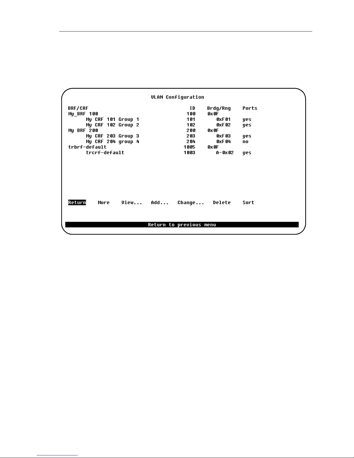
84
VLAN Configuration Screen
To open this screen from the main menu, select
→
Configuration
Use this screen to define BRFs and CRFs for the switch.
→
VLAN Configuration
→ →
.
Configuration
→
→
→ →
VLAN
BRF/CRF
ASCII name associated with the BRF or CRF. For a CRF it is synonymous with the
ELAN name on ATM LANE ports.
ID
Numeric ID. Numeric ID assigned to the BRF or CRF. This must be within the range
of 2 to 1005.
Brdg/Rng
Bridge/Ring numbers. For BRFs this is a bridge number, for CRF this is a ring
number..
Ports
This parameter is set to
ports are assigned. Note that if no ports are assigned to a BRF, it will not be
assigned a MAC address. Moreover, it is not possible to assign IP addresses to it..
Return
Returns to the previous menu.
if ports are assigned to the CRF. The value is No if no
Yes
SmartStack STS16-20RM/STS16-20FRM Token Ring Switches, P/N: 9032957-01 Switch Configuration
Page 99

More
Scrolls or refreshes the display.
View...
Zooms in a VLAN.
Add...
85
Prompts for a new ID and brings up the
VLAN Parameter Configuration
screen.
Change...
Prompts for a numeric ID of a BRF or CRF to change and brings up the
Parameter Configuration
screen.
VLAN
Delete
Lets you delete a BRF or CRF. You cannot delete a BRF if there are CRFs assigned
to it, or a CRF if there are ports assigned to it.
Switch Configuration SmartStack STS16-20RM/STS16-20FRM Token Ring Switches, P/N: 9032957-01
Page 100
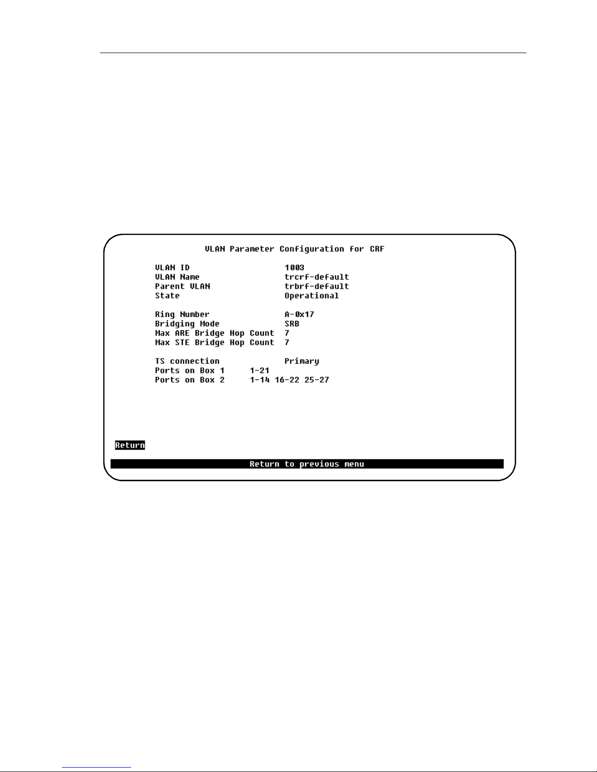
86
VLAN Parameter Configuration for CRF Screen
To open this screen, do the following:
1. From the main menu, select
VLAN Configuration
2. Select
3. When prompted, enter the VLAN ID for the CRF.
Use this screen to add or change a CRF. Note that the
deleted. Also, the
View..., Add...
trcrf-default
.
, or
Configuration
Change...
cannot be assigned to other BRFs.
→
→
VLAN Configuration
→ →
trcrf-default
→
→
→ →
cannot be
The following information is displayed on this screen:
VLAN ID
Numeric ID of the CRF. Possible values are 2 through
and 1 are reserved for the default CRFs and BRFs.
1005
VLAN Name
ASCII name associated with the CRF. Up to 32 characters are allowed. The name
must be unique. Neither a BRF nor a CRF must exist with identical names.
Par ent VLAN
BRF to which the CRF belongs.
State
Current state of the CRF. Possible values are
SmartStack STS16-20RM/STS16-20FRM Token Ring Switches, P/N: 9032957-01 Switch Configuration
1005
Operational
. Values
and
Suspended
1002
. CRFs in
through
 Loading...