

Page 1
SmartSTACK ETHERNET
ELS10-27 USER GUIDE
ETHERNET SWITCH
ELS10-27TX
RESET
COM
PWR
CPU
PORT STATUS MODE
STATUS
TX ACT FDX MON
RX COL 100 USR
LINK
LINK
LINK
LINK
LINK
LINK
LINK
LINK
LINK
LINK
STATUS
STATUS
STATUS
STATUS
STATUS
STATUS
STATUS
STATUS
2X 4X 6X 8X 10X 12X 14X 16X 18X 20X 22X 24X
LINK
STATUS
STATUS
STATUS
LINK
10BASE-T/100BASE-TX
STATUS
LINK
25X 26X 27X
EPIM100
LINK
LINK
STATUS
STATUS
26
STATUS
27
9032800-01
Page 2

Page 3

NOTICE
Cabletron Systems reserves the right to make changes in specifications and other information
contained in this document without prior notice. The reader should in all cases consult Cabletron
Systems to determine whether any such changes have been made.
The hardware, firmware, or software described in this manual is subject to change without notice.
IN NO EVENT SHALL CABLETRON SYSTEMS BE LIABLE FOR ANY INCIDENTAL,
INDIRECT, SPECIAL, OR CONSEQUENTIAL DAMAGES WHATSOEVER (INCLUDING BUT
NOT LIMITED TO LOST PROFITS) ARISING OUT OF OR RELATED TO THIS MANUAL OR
THE INFORMATION CONTAINED IN IT, EVEN IF CABLETRON SYSTEMS HAS BEEN
ADVISED OF, KNOWN, OR SHOULD HAVE KNOWN, THE POSSIBILITY OF SUCH
DAMAGES.
1999 by Cabletron Systems, Inc., P.O. Box 5005, Rochester, NH 03866-5005
All Rights Reserved
Printed in the United States of America
Order Number: 9032800-01 May 1999
Cabletron Systems, SPECTRUM
ELS10-27TX, FEPIM, FEPIM-TX,
All other product names mentioned in this manual may be trademarks or registered trademarks of
their respective companies.
, and
and
LANVIEW
FEPIM-FX
are registered trademarks and
are trademarks of Cabletron Systems, Inc.
SmartSTACK,
i
Page 4

Notice
FCC NOTICE
This device complies with Part 15 of the FCC rules. Operation is subject to the following two
conditions: (1) this device may not cause harmful interference, and (2) this device must accept any
interference received, including interference that may cause undesired operation.
NOTE:
device, pursuant to Part 15 of the FCC rules. These limits are designed to provide reasonable
protection against harmful interference when the equipment is operated in a commercial environment.
This equipment uses, generates, and can radiate radio frequency energy and if not installed in
accordance with the operator’s manual, may cause harmful interference to radio communications.
Operation of this equipment in a residential area is likely to cause interference in which case the user
will be required to correct the interference at his own expense.
WARNING:
party responsible for compliance could void the user’s authority to operate the equipment.
This equipment has been tested and found to comply with the limits for a Class A digital
Changes or modifications made to this device which are not expressly approv ed by the
INDUSTRY CANADA NOTICE
This digital apparatus does not exceed the Class A limits for radio noise emissions from digital
apparatus set out in the Radio Interference Regulations of the Canadian Department of
Communications.
Le présent appareil numérique n’émet pas de bruits radioélectriques dépassant les limites applicables
aux appareils numériques de la class A prescrites dans le Règlement sur le brouillage radioélectrique
édicté par le ministère des Communications du Canada.
VCCI NOTICE
This is a Class A product based on the standard of the Voluntary Control Council for Interference by
Information Technology Equipment (VCCI). If this equipment is used in a domestic environment,
radio disturbance may arise. When such trouble occurs, the user may be required to take corrective
actions.
ii
Page 5

Notice
CABLETRON SYSTEMS, INC.
PROGRAM LICENSE AGREEMENT
IMPORTANT: THIS LICENSE APPLIES FOR USE OF PR ODUCT IN THE FOLLOWING
GEOGRAPHICAL REGIONS:
CANADA
MEXICO
CENTRAL AMERICA
SOUTH AMERICA
BEFORE OPENING OR UTILIZING THE ENCLOSED PRODUCT,
CAREFULLY READ THIS LICENSE AGREEMENT.
This document is an agreement (“Agreement”) between You, the end user, and Cabletron
Systems, Inc. (“Cabletron”) that sets forth your rights and obligations with respect to the Cabletron
software program (“Program”) in the package. The Program may be contained in firmware, chips or
other media. UTILIZING THE ENCLOSED PRODUCT, YOU ARE AGREEING TO BECOME
BOUND BY THE TERMS OF THIS AGREEMENT, WHICH INCLUDES THE LICENSE AND
THE LIMITATION OF WARRANTY AND DISCLAIMER OF LIABILITY. IF YOU DO NOT
AGREE TO THE TERMS OF THIS AGREEMENT, RETURN THE UNOPENED PRODUCT TO
CABLETRON OR YOUR DEALER, IF ANY, WITHIN TEN (10) DAYS FOLLO WING THE DATE
OF RECEIPT FOR A FULL REFUND.
IF YOU HAVE ANY QUESTIONS ABOUT THIS AGREEMENT, CONTACT CABLETRON
SYSTEMS (603) 332-9400. Attn: Legal Department.
1. LICENSE.
package subject to the terms and conditions of this License Agreement.
You may not copy, reproduce or transmit any part of the Program except as permitted by the
Copyright Act of the United States or as authorized in writing by Cabletron.
2. OTHER RESTRICTIONS.
Program.
3. APPLICABLE LAW.
laws and in the state and federal courts of New Hampshire. You accept the personal jurisdiction and
venue of the New Hampshire courts.
4. EXPORT REQUIREMENTS.
regulation by agencies of the U.S. Government, including the U.S. Department of Commerce, which
prohibit export or diversion of certain technical products to certain countries, unless a license to export
the product is obtained from the U.S. Government or an exception from obtaining such license may be
relied upon by the exporting party.
If the Program is exported from the United States pursuant to the License Exception CIV under
the U.S. Export Administration Regulations, You agree that You are a civil end user of the Program
and agree that You will use the Program for civil end uses only and not for military purposes.
You have the right to use only the one (1) copy of the Program provided in this
You may not reverse engineer, decompile, or disassemble the
This License Agreement shall be interpreted and governed under the
You understand that Cabletron and its Affiliates are subject to
iii
Page 6

Notice
If the Program is exported from the United States pursuant to the License Exception TSR under
the U.S. Export Administration Regulations, in addition to the restriction on transfer set forth in
Sections 1 or 2 of this Agreement, You agree not to (i) reexport or release the Program, the source
code for the Program or technology to a national of a country in Country Groups D:1 or E:2 (Albania,
Armenia, Azerbaijan, Belarus, Bulgaria, Cambodia, Cuba, Estonia, Georgia, Iraq, Kazakhstan,
Kyrgyzstan, Laos, Latvia, Libya, Lithuania, Moldova, North Korea, the People’s Republic of China,
Romania, Russia, Rwanda, Tajikistan, Turkmenistan, Ukraine, Uzbekistan, Vietnam, or such other
countries as may be designated by the United States Government), (ii) export to Country Groups D:1
or E:2 (as defined herein) the direct product of the Program or the technology, if such foreign
produced direct product is subject to national security controls as identified on the U.S. Commerce
Control List, or (iii) if the direct product of the technology is a complete plant o r any major
component of a plant, export to Country Groups D:1 or E:2 the direct product of the plant or a major
component thereof, if such foreign produced direct product is subject to national security controls as
identified on the U.S. Commerce Control List or is subject to State Department controls under the
U.S. Munitions List.
5. UNITED STATES GOVERNMENT RESTRICTED RIGHTS.
was developed solely at private expense; (ii) contains “restricted computer software” submitted with
restricted rights in accordance with section 52.227-19 (a) through (d) of the Commercial Computer
Software-Restricted Rights Clause and its successors, and (iii) in all respects is proprietary data
belonging to Cabletron and/or its suppliers. For Department of Defense units, the Product is considered
commercial computer software in accordance with DFARS section 227.7202-3 and its successors, and
use, duplication, or disclosure by the Government is subject to restrictions set forth herein.
6. EXCLUSION OF WARRANTY.
writing, Cabletron makes no warranty, expressed or implied, concerning the Program (including its
documentation and media).
CABLETRON DISCLAIMS ALL WARRANTIES, OTHER THAN THOSE SUPPLIED TO
YOU BY CABLETRON IN WRITING, EITHER EXPRESS OR IMPLIED, INCLUDING BUT
NOT LIMITED TO IMPLIED WARRANTIES OF MERCHANTABILITY AND FITNESS FOR A
PARTICULAR PURPOSE, WITH RESPECT TO THE PROGRAM, THE ACCOMPANYING
WRITTEN MATERIALS, AND ANY A CCOMPANYING HARDWARE.
7. NO LIABILITY FOR CONSEQUENTIAL DAMAGES.
CABLETRON OR ITS SUPPLIERS BE LIABLE FOR ANY DAMAGES WHATSOEVER
(INCLUDING, WITHOUT LIMITATION, DAMAGES FOR LOSS OF BUSINESS, PROFITS,
BUSINESS INTERRUPTION, LOSS OF BUSINESS INFORMATION, SPECIAL, INCIDENTAL,
CONSEQUENTIAL, OR RELIANCE DAMAGES, OR OTHER LOSS) ARISING OUT OF THE
USE OR INABILITY TO USE THIS CABLETRON PRODUCT, EVEN IF CABLETRON HAS
BEEN ADVISED OF THE POSSIBILITY OF SUCH DAMAGES. BECAUSE SOME STATES DO
NOT ALLOW THE EXCLUSION OR LIMITATION OF LIABILITY FOR CONSEQUENTIAL OR
INCIDENTAL DAMAGES, OR IN THE DURATION OR LIMITATION OF IMPLIED
WARRANTIES IN SOME INSTANCES, THE ABOVE LIMITATION AND EXCLUSIONS MAY
NOT APPLY TO YOU.
Except as may be specifically provided by Cabletron in
IN NO EVENT SHALL
The enclosed Product (i)
iv
Page 7

Notice
CABLETRON SYSTEMS SALES AND SERVICE, INC.
PROGRAM LICENSE AGREEMENT
IMPORTANT: THIS LICENSE APPLIES FOR USE OF PRODUCT IN THE UNITED
STATES OF AMERICA AND BY UNITED STATES OF AMERICA
GOVERNMENT END USERS.
BEFORE OPENING OR UTILIZING THE ENCLOSED PRODUCT,
CAREFULLY READ THIS LICENSE AGREEMENT.
This document is an agreement (“Agreement”) between You, the end user, and Cabletron Systems
Sales and Service, Inc. (“Cabletron”) that sets forth your rights and obligations with respect to the
Cabletron software program (“Program”) in the package. The Program may be contained in firmware,
chips or other media. UTILIZING THE ENCLOSED PRODUCT, YOU ARE AGREEING TO
BECOME BOUND BY THE TERMS OF THIS AGREEMENT, WHICH INCLUDES THE
LICENSE AND THE LIMITATION OF WARRANTY AND DISCLAIMER OF LIABILITY. IF
YOU DO NOT AGREE TO THE TERMS OF THIS AGREEMENT, RETURN THE UNOPENED
PRODUCT TO CABLETRON OR YOUR DEALER, IF ANY, WITHIN TEN (10) DAYS
FOLLOWING THE DATE OF RECEIPT FOR A FULL REFUND.
IF YOU HAVE ANY QUESTIONS ABOUT THIS AGREEMENT, CONTACT CABLETRON
SYSTEMS (603) 332-9400. Attn: Legal Department.
1. LICENSE.
package subject to the terms and conditions of this License Agreement.
You may not copy, reproduce or transmit any part of the Program except as permitted by the
Copyright Act of the United States or as authorized in writing by Cabletron.
2. OTHER RESTRICTIONS.
Program.
3. APPLICABLE LAW.
laws and in the state and federal courts of New Hampshire. You accept the personal jurisdiction and
venue of the New Hampshire courts.
4. EXPORT REQUIREMENTS.
regulation by agencies of the U.S. Government, including the U.S. Department of Commerce, which
prohibit export or diversion of certain technical products to certain countries, unless a license to export
the product is obtained from the U.S. Government or an exception from obtaining such license may be
relied upon by the exporting party.
If the Program is exported from the United States pursuant to the License Exception CIV under
the U.S. Export Administration Regulations, You agree that You are a civil end user of the Program
and agree that You will use the Program for civil end uses only and not for military purposes.
You have the right to use only the one (1) copy of the Program provided in this
You may not reverse engineer, decompile, or disassemble the
This License Agreement shall be interpreted and governed under the
You understand that Cabletron and its Affiliates are subject to
v
Page 8

Notice
If the Program is exported from the United States pursuant to the License Exception TSR under
the U.S. Export Administration Regulations, in addition to the restriction on transfer set forth in
Sections 1 or 2 of this Agreement, You agree not to (i) reexport or release the Program, the source
code for the Program or technology to a national of a country in Country Groups D:1 or E:2 (Albania,
Armenia, Azerbaijan, Belarus, Bulgaria, Cambodia, Cuba, Estonia, Georgia, Iraq, Kazakhstan,
Kyrgyzstan, Laos, Latvia, Libya, Lithuania, Moldova, North Korea, the People’s Republic of China,
Romania, Russia, Rwanda, Tajikistan, Turkmenistan, Ukraine, Uzbekistan, Vietnam, or such other
countries as may be designated by the United States Government), (ii) export to Country Groups D:1
or E:2 (as defined herein) the direct product of the Program or the technology, if such foreign
produced direct product is subject to national security controls as identified on the U.S. Commerce
Control List, or (iii) if the direct product of the technology is a complete plant o r any major
component of a plant, export to Country Groups D:1 or E:2 the direct product of the plant or a major
component thereof, if such foreign produced direct product is subject to national security controls as
identified on the U.S. Commerce Control List or is subject to State Department controls under the
U.S. Munitions List.
5. UNITED STATES GOVERNMENT RESTRICTED RIGHTS.
was developed solely at private expense; (ii) contains “restricted computer software” submitted with
restricted rights in accordance with section 52.227-19 (a) through (d) of the Commercial Computer
Software-Restricted Rights Clause and its successors, and (iii) in all respects is proprietary data
belonging to Cabletron and/or its suppliers. For Department of Defense units, the Product is considered
commercial computer software in accordance with DFARS section 227.7202-3 and its successors, and
use, duplication, or disclosure by the Government is subject to restrictions set forth herein.
6. EXCLUSION OF WARRANTY.
writing, Cabletron makes no warranty, expressed or implied, concerning the Program (including its
documentation and media).
CABLETRON DISCLAIMS ALL WARRANTIES, OTHER THAN THOSE SUPPLIED TO
YOU BY CABLETRON IN WRITING, EITHER EXPRESS OR IMPLIED, INCLUDING BUT
NOT LIMITED TO IMPLIED WARRANTIES OF MERCHANTABILITY AND FITNESS FOR A
PARTICULAR PURPOSE, WITH RESPECT TO THE PROGRAM, THE ACCOMPANYING
WRITTEN MATERIALS, AND ANY A CCOMPANYING HARDWARE.
7. NO LIABILITY FOR CONSEQUENTIAL DAMAGES.
CABLETRON OR ITS SUPPLIERS BE LIABLE FOR ANY DAMAGES WHATSOEVER
(INCLUDING, WITHOUT LIMITATION, DAMAGES FOR LOSS OF BUSINESS, PROFITS,
BUSINESS INTERRUPTION, LOSS OF BUSINESS INFORMATION, SPECIAL, INCIDENTAL,
CONSEQUENTIAL, OR RELIANCE DAMAGES, OR OTHER LOSS) ARISING OUT OF THE
USE OR INABILITY TO USE THIS CABLETRON PRODUCT, EVEN IF CABLETRON HAS
BEEN ADVISED OF THE POSSIBILITY OF SUCH DAMAGES. BECAUSE SOME STATES DO
NOT ALLOW THE EXCLUSION OR LIMITATION OF LIABILITY FOR CONSEQUENTIAL OR
INCIDENTAL DAMAGES, OR IN THE DURATION OR LIMITATION OF IMPLIED
WARRANTIES IN SOME INSTANCES, THE ABOVE LIMITATION AND EXCLUSIONS MAY
NOT APPLY TO YOU.
Except as may be specifically provided by Cabletron in
IN NO EVENT SHALL
The enclosed Product (i)
vi
Page 9

Notice
CABLETRON SYSTEMS LIMITED
PROGRAM LICENSE AGREEMENT
IMPORTANT: THIS LICENSE APPLIES FOR THE USE OF THE PRODUCT IN THE
FOLLOWING GEOGRAPHICAL REGIONS:
EUROPE
MIDDLE EAST
AFRICA
ASIA
AUSTRALIA
PACIFIC RIM
BEFORE OPENING OR UTILIZING THE ENCLOSED PRODUCT,
CAREFULLY READ THIS LICENSE AGREEMENT.
This document is an agreement (“Agreement”) between You, the end user, and Cabletron
Systems Limited (“Cabletron”) that sets forth your rights and obligations with respect to the
Cabletron software program (“Program”) in the package. The Program may be contained in firmware,
chips or other media. UTILIZING THE ENCLOSED PRODUCT, YOU ARE AGREEING TO
BECOME BOUND BY THE TERMS OF THIS AGREEMENT, WHICH INCLUDES THE
LICENSE AND THE LIMITATION OF WARRANTY AND DISCLAIMER OF LIABILITY. IF
YOU DO NOT AGREE TO THE TERMS OF THIS AGREEMENT, RETURN THE UNOPENED
PRODUCT TO CABLETRON OR YOUR DEALER, IF ANY, WITHIN TEN (10) DAYS
FOLLOWING THE DATE OF RECEIPT FOR A FULL REFUND.
IF YOU HAVE ANY QUESTIONS ABOUT THIS AGREEMENT, CONTACT CABLETRON
SYSTEMS (603) 332-9400. Attn: Legal Department.
1. LICENSE.
package subject to the terms and conditions of this License Agreement.
You may not copy, reproduce or transmit any part of the Program except as permitted by the
Copyright Act of the United States or as authorized in writing by Cabletron.
2. OTHER RESTRICTIONS.
Program.
3. APPLICABLE LAW.
law. The English courts shall have exclusive jurisdiction in the event of any disputes.
4. EXPORT REQUIREMENTS.
regulation by agencies of the U.S. Government, including the U.S. Department of Commerce, which
prohibit export or diversion of certain technical products to certain countries, unless a license to export
the product is obtained from the U.S. Government or an exception from obtaining such license may be
relied upon by the exporting party.
If the Program is exported from the United States pursuant to the License Exception CIV under
the U.S. Export Administration Regulations, You agree that You are a civil end user of the Program
and agree that You will use the Program for civil end uses only and not for military purposes.
You have the right to use only the one (1) copy of the Program provided in this
You may not reverse engineer, decompile, or disassemble the
This License Agreement shall be governed in accordance with English
You understand that Cabletron and its Affiliates are subject to
vii
Page 10

Notice
If the Program is exported from the United States pursuant to the License Exception TSR under
the U.S. Export Administration Regulations, in addition to the restriction on transfer set forth in
Sections 1 or 2 of this Agreement, You agree not to (i) reexport or release the Program, the source
code for the Program or technology to a national of a country in Country Groups D:1 or E:2 (Albania,
Armenia, Azerbaijan, Belarus, Bulgaria, Cambodia, Cuba, Estonia, Georgia, Iraq, Kazakhstan,
Kyrgyzstan, Laos, Latvia, Libya, Lithuania, Moldova, North Korea, the People’s Republic of China,
Romania, Russia, Rwanda, Tajikistan, Turkmenistan, Ukraine, Uzbekistan, Vietnam, or such other
countries as may be designated by the United States Government), (ii) export to Country Groups D:1
or E:2 (as defined herein) the direct product of the Program or the technology, if such foreign
produced direct product is subject to national security controls as identified on the U.S. Commerce
Control List, or (iii) if the direct product of the technology is a complete plant o r any major
component of a plant, export to Country Groups D:1 or E:2 the direct product of the plant or a major
component thereof, if such foreign produced direct product is subject to national security controls as
identified on the U.S. Commerce Control List or is subject to State Department controls under the
U.S. Munitions List.
5. UNITED STATES GOVERNMENT RESTRICTED RIGHTS.
was developed solely at private expense; (ii) contains “restricted computer software” submitted with
restricted rights in accordance with section 52.227-19 (a) through (d) of the Commercial Computer
Software-Restricted Rights Clause and its successors, and (iii) in all respects is proprietary data
belonging to Cabletron and/or its suppliers. For Department of Defense units, the Product is considered
commercial computer software in accordance with DFARS section 227.7202-3 and its successors, and
use, duplication, or disclosure by the Government is subject to restrictions set forth herein.
6. EXCLUSION OF WARRANTY.
writing, Cabletron makes no warranty, expressed or implied, concerning the Program (including its
documentation and media).
CABLETRON DISCLAIMS ALL WARRANTIES, OTHER THAN THOSE SUPPLIED TO
YOU BY CABLETRON IN WRITING, EITHER EXPRESS OR IMPLIED, INCLUDING BUT
NOT LIMITED TO IMPLIED WARRANTIES OF MERCHANTABILITY AND FITNESS FOR A
PARTICULAR PURPOSE, WITH RESPECT TO THE PROGRAM, THE ACCOMPANYING
WRITTEN MATERIALS, AND ANY A CCOMPANYING HARDWARE.
7.
NO LIABILITY FOR CONSEQUENTIAL DAMAGES. IN NO EVENT SHALL
CABLETRON OR ITS SUPPLIERS BE LIABLE FOR ANY DAMAGES WHATSOEVER
(INCLUDING, WITHOUT LIMITATION, DAMAGES FOR LOSS OF BUSINESS, PROFITS,
BUSINESS INTERRUPTION, LOSS OF BUSINESS INFORMATION, SPECIAL, INCIDENTAL,
CONSEQUENTIAL, OR RELIANCE DAMAGES, OR OTHER LOSS) ARISING OUT OF THE
USE OR INABILITY TO USE THIS CABLETRON PRODUCT, EVEN IF CABLETRON HAS
BEEN ADVISED OF THE POSSIBILITY OF SUCH DAMAGES. BECAUSE SOME STATES DO
NOT ALLOW THE EXCLUSION OR LIMITATION OF LIABILITY FOR CONSEQUENTIAL OR
INCIDENTAL DAMAGES, OR IN THE DURATION OR LIMITATION OF IMPLIED
WARRANTIES IN SOME INSTANCES, THE ABOVE LIMITATION AND EXCLUSIONS MAY
NOT APPLY TO YOU.
Except as may be specifically provided by Cabletron in
The enclosed Product (i)
viii
Page 11

DECLARATION OF CONFORMITY
Notice
Application of Council Directive(s):
Manufacturer’s Name:
Manufacturer’ s Address:
European Representative Name:
European Representative Address:
Conformance to Directive(s)/Product Standards:
Equipment Type/Environment:
89/336/EEC
73/23/EEC
Cabletron Systems, Inc.
35 Industrial Way
PO Box 5005
Rochester, NH 03867
Mr. J. Solari
Cabletron Systems Limited
Nexus House, Newbury Business Park
London Road, Newbury
Berkshire RG13 2PZ, England
EC Directive 89/336/EEC
EC Directive 73/23/EEC
EN 55022
EN 50082-1
EN 60950
Networking Equipment, for use in a
Commercial or Light
Environment.
Industrial
We the undersigned, hereby declare, under our sole responsibility, that the equipment packaged
with this notice conforms to the above directives.
Manufacturer Legal Representative in Europe
Mr. Ronald Fotino Mr. J. Solari
___________________________________ ___________________________________
Full Name Full Name
Compliance Engineering Manager Managing Director - E.M.E.A.
___________________________________ ___________________________________
Title Title
Rochester, NH, USA Newbury, Berkshire, England
___________________________________ ___________________________________
Location Location
ix
Page 12

Notice
x
Page 13

CONTENTS
CHAPTER 1 INTRODUCTION
1.1 About This Manual..................................................................................1-1
1.2 Getting Help .............................................................................................1-2
1.3 Document Conventions ..........................................................................1-3
1.4 Related Documentation...........................................................................1-4
1.5 Overview...................................................................................................1-4
1.5.1 SmartSTACK Ethernet ELS10-27 Architecture..........................1-5
1.5.2 SmartSTACK Ethernet ELS10-27 Functionality ........................1-5
1.5.3 SmartSTACK Ethernet ELS10-27 Bridge Address Table........1-10
1.5.4 SmartSTACK Ethernet ELS10-27 Port Mirroring....................1-11
1.5.5 SmartSTACK Ethernet ELS10-27 Sample Applications .........1-12
1.5.6 VLANs..........................................................................................1-13
1.5.7 Configuration Commands..........................................................1-15
1.6 Local Console Manager.........................................................................1-16
1.6.1 Command Syntax Conventions.................................................1-17
CHAPTER 2 UNPACKING AND INSTALLING YOUR
SMARTSTACK ETHERNET ELS10-27
2.1 SmartSTACK Ethernet ELS10-27 Front Panel......................................2-2
2.1.1 Indicators ........................................................................................2-4
2.2 Installing an EPIM ...................................................................................2-5
2.3 Installing the SmartSTACK Ethernet ELS10-27...................................2-6
2.4 Checking the Power-up Diagnostics Sequence ...................................2-8
2.5 Connecting the Local Console Manager...............................................2-9
2.6 Connecting To the Network .................................................................2-10
2.6.1 Connecting UTP Cables ..............................................................2-10
2.6.2 Connecting a Multimode Segment to the EPIM100-FX .........2-12
CHAPTER 3 CONFIGURING YOUR
SMARTSTACK ETHERNET ELS10-27
3.1 Assigning IP Addresses ..........................................................................3-2
3.1.1 IP Address Configuration.............................................................3-2
3.1.2 Displaying IP Addresses...............................................................3-4
3.1.3 Deleting an IP Address .................................................................3-5
3.1.4 Changing a Subnet Mask..............................................................3-5
3.1.5 Setting the Default Gateway ........................................................3-5
3.2 Operational Image ...................................................................................3-6
3.3 IGMP..........................................................................................................3-7
3.4 Enabling Bridging ....................................................................................3-9
3.5 Disabling Bridging...................................................................................3-9
xi
Page 14

Contents
3.6 Displaying Bridging Functions ............................................................3-10
3.7 Enabling Trunking .................................................................................3-10
3.8 Disabling Trunking................................................................................3-12
3.9 Displaying Trunking Status..................................................................3-12
3.10 Port Mirroring.......................................................................................3-14
3.11 Defining and Deleting Workgroups..................................................3-14
3.12 Assigning a ComMunity Name .........................................................3-16
3.13 Configuring Broadcast/Multicast Storm Protection.......................3-17
3.14 Modifying MIB Variables....................................................................3-17
3.15 System Contact .....................................................................................3-18
3.16 System Name ........................................................................................3-18
3.16.1 System Location .........................................................................3-18
3.16.2 Community Names....................................................................3-19
3.16.3 Aging Parameter ........................................................................3-19
CHAPTER 4 MONITORING AND MANAGING YOUR
SMARTSTACK ETHERNET ELS10-27
4.1 SmartSTACK Ethernet ELS10-27 Management Tools ........................4-1
4.2 MIB Support..............................................................................................4-2
4.3 RMON Support ........................................................................................4-2
4.3.1 RMON High Level Description ...................................................4-3
4.3.2 RMON Details ................................................................................4-5
4.4 SmartSTACK Ethernet ELS10-27 Statistics...........................................4-6
4.4.1 Gathering Statistics ........................................................................4-7
4.4.2 System Statistics .............................................................................4-7
4.4.3 Ethernet Port Statistics ..................................................................4-8
4.5 Using LCM to Check SmartSTACK Ethernet ELS10-27 .....................4-8
4.5.1 Displaying Status ...........................................................................4-9
4.5.2 Displaying MAC Addresses.......................................................4-10
4.5.3 Displaying Manufacturing Information ...................................4-12
xii
Page 15

Contents
CHAPTER 5 SMARTSTACK ETHERNET ELS10-27
DIAGNOSTICS AND TROUBLESHOOTING
5.1 Power-up Diagnostics .............................................................................5-1
5.1.1 Power-up LED Sequence ..............................................................5-1
5.1.2 Specific Power-up Tests ................................................................5-2
5.1.3 Power-up Diagnostics Results .....................................................5-2
5.2 Responses to Failures at Power-up .......................................................5-2
5.3 Status and Activity Indicators................................................................5-3
5.4 Troubleshooting .......................................................................................5-5
5.5 SmartSTACK Ethernet ELS10-27 Does Not Power Up.......................5-5
5.5.1 Connectivity Problems..................................................................5-5
5.5.2 SmartSTACK Ethernet ELS10-27 Has Rebooted .......................5-5
5.5.3 SmartSTACK Ethernet ELS10-27 Does Not Respond
to NMS............................................................................................5-6
APPENDIX A TECHNICAL SPECIFICATIONS
A.1 SmartSTACK Ethernet ELS10-27 Specifications................................A-1
A.2 Serial Cable Pin Assignments ..............................................................A-3
A.3 10BASE-T Pin Assignments..................................................................A-4
A.4 Straight-through Wiring .......................................................................A-5
A.5 Crossover Wiring...................................................................................A-5
A.6 5 - 4 - 3 Rule.............................................................................................A-6
A.7 EPIM-100FX ............................................................................................A-6
xiii
Page 16

Contents
xiv
Page 17

CHAPTER 1
INTRODUCTION
1.1 ABOUT THIS MANUAL
This manual is for system administrators responsible for conÞguring,
monitoring, and maintaining the SmartSTACK Ethernet ELS10-27TX (also
referred to as ELS10-27). You should have a familiarity with networking
concepts and principles. In addition, a basic understanding of SNMP is
helpful.
Some SmartSTACK Ethernet ELS10-27 conÞgurations can only be done
using an SNMP-based Network Management System (NMS). Where
applicable, this manual provides instructions for using the Local Console
Manager (LCM) to perform basic conÞguration. Where it is not possible to
use LCM, general instructions and guidelines applicable to most NMSs
are provided.
The contents of each chapter are described below.
¥ Chapter 1,
provides an overview of the SmartSTACK Ethernet ELS10-27Õs
switching functions, applications, and the Local Console Manager
(LCM).
¥ Chapter 2,
ELS10-27
panels, how to install the SmartSTACK Ethernet ELS10-27, how to
connect the Local Console Manager (LCM), and how to connect the
ELS10-27 to the network.
¥ Chapter 3,
provides instructions for conÞguring the SmartSTACK Ethernet
ELS10-27 using the Local Console Manager (LCM). It also provides
some common Management Information Base (MIB) variables you
may want to change.
¥ Chapter 4,
ELS10-27
status and statistics. It also describes how to manage the SmartSTACK
Ethernet ELS10-27 Ethernet ports using the Local Console Manager
(LCM).
Introduction
Unpacking and Installing Your SmartSTACK Ethernet
, describes the SmartSTACK Ethernet ELS10-27 front and rear
Configuring Your SmartSTACK Ethernet ELS10-27
Monitoring and Managing Your SmartSTACK Ethernet
, describes how to monitor SmartSTACK Ethernet ELS10-27
, outlines the contents of this manual and
,
1-1
Page 18

Introduction
¥ Chapter 5,
Troubleshooting
SmartSTACK Ethernet ELS10-27 Diagnostics and
, describes the SmartSTACK Ethernet ELS10-27
diagnostics and provides information on troubleshooting common
problems.
¥ Appendix A,
Technical Specifications
, provides the SmartSTACK
Ethernet ELS10-27 speciÞcations and basic cabling pin assignments.
¥
Index
provides a glossary of terms speciÞc to the SmartSTACK
Ethernet ELS10-27 and the page(s) on which they are explained within
this manual.
1.2 GETTING HELP
For additional support related to this device or document, contact
Cabletron Systems using one of the following methods:
World Wide Web http://www .cabletron.com/
Phone (603) 332-9400
Internet mail [email protected]
FTP ftp://ftp.cabletron.com/
Login
Password
To send comments or suggestions concerning this document, contact the
Cabletron Systems Technical Writing Department via the following
email address:
Make sure to include the document Part Number in the email message.
anonymous
your email address
Before calling Cabletron Systems, have the following information ready:
¥ Your Cabletron Systems service contract number
¥ A description of the failure
¥ A description of any action(s) already taken to resolve the problem
(e.g., changing mode switches, rebooting the unit, etc.)
¥ The serial and revision numbers of all involved Cabletron Systems
products in the network
¥ A description of your network environment (layout, cable type, etc.)
1-2
Page 19

Introduction
¥ Network load and frame size at the time of trouble (if known)
¥ The device history (i.e., have you returned the device before, is this a
recurring problem, etc.)
¥ Any previous Return Material Authorization (RMA) numbers
1.3 DOCUMENT CONVENTIONS
The following conventions are used throughout this document:
LCM commands, prompts, and information displayed by the computer
appear in Courier typeface, for example:
Current Number of Learned Addresses: 133
Information that you enter appears in Courier bold typeface, for example:
ELS10-27 >
status
Information that you need to enter with a command is enclosed in angle
brackets < >. For example, you must enter an IP address to execute the
ipaddr <IP address>
ELS10-27 >
command:
ipaddr 192.138.217.40
Field value options appear in bold typeface.
The following conventions are also used in this document:
Note:
Calls the readerÕs attention to any item of information that may be of
special importance.
Tip:
Caution:
Warning:
Conveys helpful hints concerning procedures or actions.
Contains information essential to avoid damage to the equipment.
Warns against an action that could result in equipment damage,
personal injury or death.
1-3
Page 20
Introduction
1.4 RELATED DOCUMENTATION
The following documentation may assist the user in using this product:
¥
Interconnections, Bridges and Routers,
Radia Perlman, Addison Wesley ©
1992.
¥
Internetworking with TCP/IP: Principles, Protocols, and Architecture
(2nd
edition), Volumes I and II, Douglas Comer, Prentice Hall © 1991.
¥
The Simple Book, An Introduction to Management of TCP/IP-based
internets
, Marshall T. Rose, Prentice Hall © Second Edition, 1994.
1.5 OVERVIEW
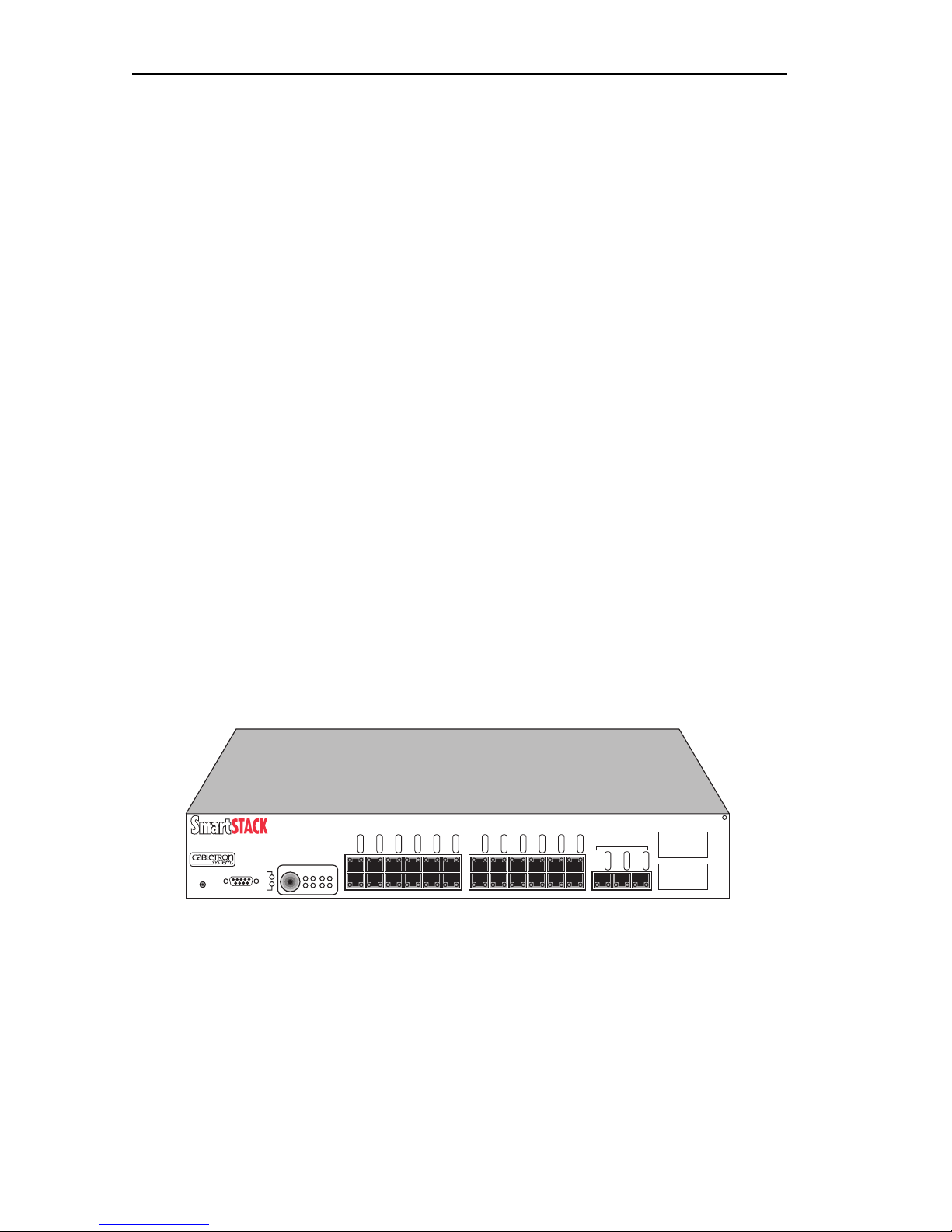
The SmartSTACK Ethernet ELS10-27 provides a low cost, high
performance solution for 10/100 Mbps switched networks. The
SmartSTACK Ethernet ELS10-27TX is conÞgured with twenty-seven RJ45
ports supporting twenty-four autonegotiating 10 Mbps ports and three
autonegotiating 10/100 Mbps ports. The device also features two EPIM100 slots that allow the user to install up to two EPIM-100s to provide
multimode Þber uplinks (with potential for single mode Þber). It also
includes an RS232C port for out-of-band management.
.
ETHERNET SWITCH
ELS10-27TX
RESET
COM
LINK
LINK
LINK
LINK
LINK
LINK
LINK
LINK
LINK
LINK
STATUS
STATUS
STATUS
STATUS
STATUS
STATUS
PORT STATUS MODE
STATUS
PWR
TX ACT FDX MON
CPU
RX COL 100 USR
2X 4X 6X 8X 10X 12X 14X 16X 18X 20X 22X 24X
STATUS
LINK
STATUS
STATUS
STATUS
10BASE-T/100BASE-TX
LINK
STATUS
STATUS
LINK
LINK
STATUS
STATUS
25X 26X 27X
EPIM100
26
LINK
STATUS
27
Figure 1-1. SmartSTACK Ethernet ELS10-27 Front Panel
The SmartSTACK Ethernet ELS10-27:
¥ Provides dedicated bandwidth for each network connected to its ports.
¥ Provides full store and forward bridging functionality.
¥ Provides complete error checking functionality.
1-4
Page 21

Introduction
¥ Provides port trunking to increase bandwidth.
¥ Provides a user selectable monitor port for enhanced troubleshooting.
¥ Supports Auto-negotiation.
¥ Operates in either Half Duplex or Full Duplex modes on all ports.
¥ Implements the Spanning Tree protocol (802.1D).
¥ ConÞgured with factory-set defaults for immediate plug-and-play
capability (IP address is not conÞgured at factory).
In addition, the SmartSTACK Ethernet ELS10-27 offers the following
features that can help you manage and maintain your network:
¥ RMON support
¥ ConÞguration and management using the Simple Network
Management Protocol (SNMP) with either an in-band or out-of-band
connection.
¥ Protection against broadcast/multicast storms.
¥ Ability to deÞne virtual workgroups for more efÞcient bandwidth
usage. The SmartSTACK Ethernet ELS10-27 ports can be segmented
into 8 separate domains.
¥ Compilation of statistics, including Broadcast and Unicast (by port) for
trafÞc generated to a SmartSTACK Ethernet ELS10-27 segment.
1.5.1 SmartSTACK Ethernet ELS10-27 Architecture
The SmartSTACK Ethernet ELS10-27 supports all standard Ethernet-toEthernet bridging functions, has (24) 10 Mbps IEEE 802.3/Ethernet full
duplex 10Base-T ports, (3) standard 10/100 Mbps TX full duplex Fast
Ethernet ports, and (2) optional 100BaseFX full or half duplex Þber EPIM
ports.
1.5.2 SmartSTACK Ethernet ELS10-27 Functionality
¥ Support IEEE 802.1D Spanning Tree Protocol for MAC Bridges.
A 2K entry Filtering Database with learning and aging of entries.
1-5
Page 22

Introduction
¥ Per Ethernet and Fast Ethernet port packet buffer supporting (1,061)
128-byte packets or (88) 1518-byte packets per port.
¥ Per switch packet buffering is (28,672) 128-byte packets and (2,389)
1518-byte packets.
Two modes of operation are supported, 802.1D and 802.1Q. These are
mutually exclusive.
Provide store and forward capability with the ability to switch to
fragment free cut-through (starts forwarding after Þrst 128 bytes
received) on a per system basis. Autonegotiation on all ports for full or
half duplex mode. Autonegotiation of 10/100 Mbps for Fast Ethernet
ports.
Two forms of ßow control are supported.
¥ In full duplex mode, 802.3x pause frames are supported.
¥ In half duplex mode, back pressure is supported.
Broadcast storm control on a per port basis will limit transmissions.
Local port mirroring of all ports for valid frames on both Rx and Tx using
a user selectable mirror port or MAC address based mirroring.
SmartSTACK Ethernet ELS10-27 offers two basic methods to conÞgure
the IP address for the device. These two methods are BOOTP and LCM.
¥ The SmartSTACK Ethernet ELS10-27 utilizes the BOOTP protocol to
obtain an IP Address that may be used by this unit.
¥ ConÞguration via LCM of the device IP address and Default Gateway
The Operational Image is maintained by use of TFTP in conjunction with
BOOTP.
The SmartSTACK Ethernet ELS10-27 acts as an IP Multicast Þlter by
snooping IGMP messages, IP Multicast UDP messages and other IPM
routing messages.
Two forms of VLANs will be supported.
¥ Virtual Workgroup support. Up to 8 workgroups may be conÞgured,
with up to 27 ports in a workgroup. These conÞgurable
broadcast/multicast/unicast Þltering parameters for the Virtual
Workgroup feature are only supported in 802.1D mode.
1-6
Page 23

Introduction
¥ IEEE 802.1Q is a standard for virtual bridged local area networks
(VLANs). Thirty-two simultaneous VLANs are supported.
Support RMON Ethernet Statistics, Alarms, Events, and History group.
Network interfaces supported.
¥ All twisted pair copper ports are RJ-45 with internal crossover.
¥ The device has two uplink slots which support a single interface
module each. Each interface supports one EPIM-100FX. The interface
module is user installable and is hot-swappable. Use of an EPIM in the
uplink slot disables one of the Þxed 10/100 Mbps ports.
Several forms of user interface are available for conÞguration and/or
statistics monitoring.
¥ Local Console Management (LCM)
¥ Up to 4 simultaneous Telnet sessions are supported.
Telnet, and SNMP can be accessed by either the out-of-band COM port
via PPP (Point-to-Point Protocol) or any in-band Ethernet port.
Non-volatile memory is provided to store all user modiÞable
conÞguration parameters.
Upload and download of conÞguration parameters:
A system reset button is provided on the front panel. The SmartSTACK
Ethernet ELS10-27 will supply port level and system level information via
front panel LEDs. Each port has a Link LED and a function LED. The
EPIM-100FX has a single green LED which indicates link. When an EPIM
is in use the function indicator for one of the Þxed ports is used to
indicate the status of the corresponding EPIM.
Serial Number/Revision IdentiÞcation is displayed within the user
interfaces.
Watchdog timer feature.
The SmartSTACK Ethernet ELS10-27 enables you to link two or more
Local Area Networks (LANs) together. To accomplish this, the
SmartSTACK Ethernet ELS10-27 regulates network trafÞc on the basis of
the source and destination addresses that are in each data packet it
receives.
1-7
Page 24
Introduction
The SmartSTACK Ethernet ELS10-27 is protocol-transparent, meaning it
can handle different types of network trafÞc regardless of the network
protocol, such as IP and IPX. As the SmartSTACK Ethernet ELS10-27
reads addresses from the packets it processes, it builds a dynamic
database of addresses called the
Bridge Address Table
. In this way, the
SmartSTACK Ethernet ELS10-27 continuously learns the addresses of all
connected devices. Consequently, you can add new devices to the
network, change device addresses, and remove devices from the network
without having to reconÞgure the SmartSTACK Ethernet ELS10-27.
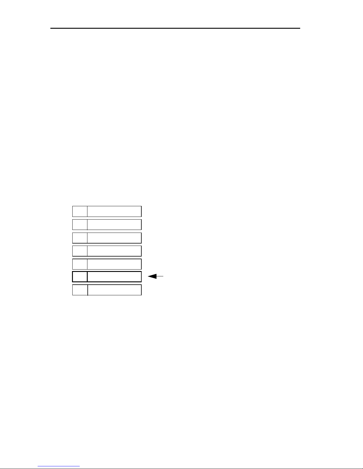
The Open System Interconnection (OSI) Reference Model, developed by
the International Standards Organization (ISO), identiÞes the levels of
functionality inherent in each of its seven layers. The SmartSTACK
Ethernet ELS10-27 operates at the Media Access Control (MAC) sub-layer
of the Data Link layer.
7
Application
Presentation
6
5
Session
Transport
4
3
Network
2
1
Data Link
Physical
Figure 1-2. OSI Reference Model
ELS10-27 operates at Layer 2
Because the SmartSTACK Ethernet ELS10-27 does not process any
Network Layer information, it provides a high level of performance in
terms of packet throughput. In addition, the SmartSTACK Ethernet
ELS10-27 does not need to learn network topology, requiring less
programming and conÞguration time.
Store and Forward Switching
As an intelligent Ethernet switch, the SmartSTACK Ethernet ELS10-27
uses store and forward switching. Store and forward switching allows the
SmartSTACK Ethernet ELS10-27 to temporarily store packets until
network resources, typically an unused link, are available for forwarding.
1-8
Page 25
Introduction
This allows for complete error checking, and limits the amount of time
between a device request access to the network, and permission to
transmit. In addition, full store and forward switching ensures data
integrity; preventing network error conditions from being generated
throughout the network.
Discarding Local Traffic
The SmartSTACK Ethernet ELS10-27 checks all incoming packets for the
destination address against the Bridge Address Table. If a packetÕs
destination address is not on the same network segment as the
originating packet, the SmartSTACK Ethernet ELS10-27 forwards the
packet to the network segment associated with that destination address,
if known. However, if the packetÕs source and destination addresses are
on the same network segment, known as local trafÞc, the packet is
automatically discarded (i.e., ignored by the SmartSTACK Ethernet
ELS10-27).
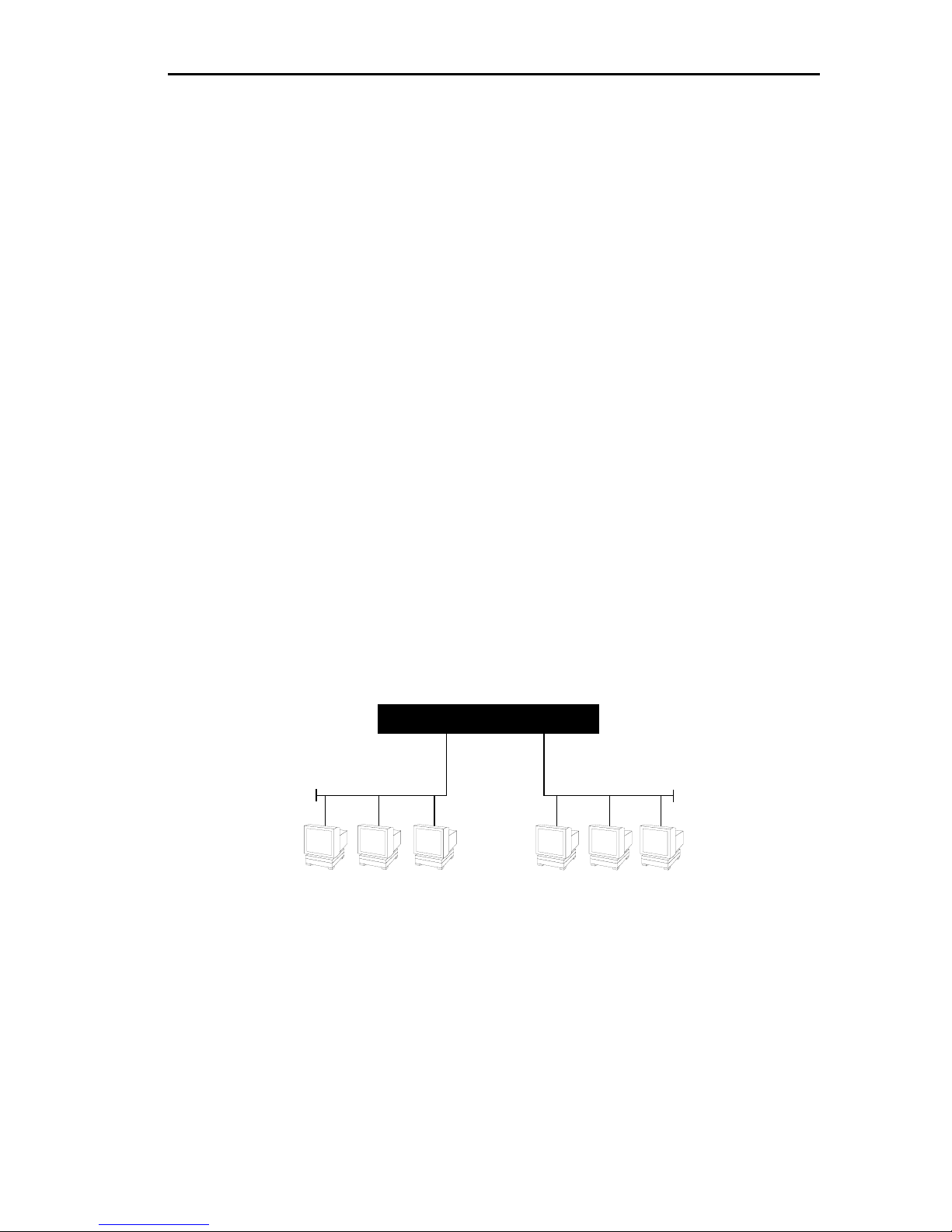
For example, a Þle transmitted from Workstation A, to Workstation C, in
Figure 1-3, does not need to leave LAN 1. The SmartSTACK Ethernet
ELS10-27 connected to LANs 1 and 2 sees all trafÞc from LAN 1,
including LAN 1 local trafÞc.
ELS10-27
LAN 1
LAN 2
ABC
Figure 1-3. Typical Switching Application
By forwarding only packets addressed to devices on other network
segments, the SmartSTACK Ethernet ELS10-27 reduces unnecessary
trafÞc and thereby enhances the overall performance of the network.
Note: If the packet address is not found in the Bridge Address Table, it will be
forwarded (flooded) to all network segments.
1-9
Page 26

Introduction
Spanning T ree Algorithm
The SmartSTACK Ethernet ELS10-27 supports the IEEE 802.1D Spanning
Tree algorithm. The Spanning Tree algorithm converts multiple LANs
into a Òspanning treeÓ of networks. It is used to prevent bridging loops.
This standard deÞnes a logical (not physical) network conÞguration
consisting of one extended LAN without active duplicate paths between
spanning tree bridges.
The SmartSTACK Ethernet ELS10-27, along with other IEEE 802.1D
Spanning Tree compliant bridges in the network, dynamically conÞgure
the network topology into a single Spanning Tree by exchanging Bridge
Protocol Data Units (BPDUs). Typically, each LAN segment is sent one
BPDU every two seconds (this is the default setting).
When there are multiple SmartSTACK Ethernet ELS10-27s connecting
LANs in a loop, the Spanning Tree algorithm determines which
SmartSTACK Ethernet ELS10-27 should forward packets to the LAN. If
there is a cable break or a port failure, the network topology is
automatically reconÞgured by the Spanning Tree protocol to create an
alternate path to the LAN.
1.5.3 SmartSTACK Ethernet ELS10-27 Bridge Address
Table
In 802.1D mode, the SmartSTACK Ethernet ELS10-27 creates and
maintains a dynamic database of addresses called the Bridge Address
Table. The SmartSTACK Ethernet ELS10-27 examines every packet to
determine its source address and LAN segment origin. It then compares
the source address and segment information it Þnds to the entries in the
Bridge Address Table.
In 802.1Q mode, if a packetÕs address is not already stored in the Bridge
Address Table, the SmartSTACK Ethernet ELS10-27 adds the learned
address, associated segment number, and a timer value indicating the age
of the observation. Consequently, the SmartSTACK Ethernet ELS10-27
knows the address and associated segment number the next time it sees
that address. By using the information stored in the Bridge Address Table,
the SmartSTACK Ethernet ELS10-27 is able to quickly forward each
packet to the correct LAN segment.
The SmartSTACK Ethernet ELS10-27 learns addresses from all packets,
including data transmissions and Òkeep aliveÓ packets (packets sent by
1-10
Page 27

Introduction
an idle station to let other stations know it is present and functional).
When devices are added to the network, removed from it, or relocated,
you do not have to reconÞgure the SmartSTACK Ethernet ELS10-27. The
unit automatically learns new device addresses, recognizes when a
previously used address is missing, or when a device has been moved to
a new LAN segment.
An address stored in the Bridge Address Table is discarded if there is no
subsequent activity from that address after a conÞgured length of time
(Þve minutes by default). This aging process ensures that the Bridge
Address Table is continually updated.
Addresses are continually added to and deleted from the Bridge Address
Table, reßecting the dynamic nature of internetwork trafÞc.
Each dynamic entry includes:
¥ An Ethernet MAC address
¥ A single port number of the LAN on which the address resides
¥ The age of the entry
The SmartSTACK Ethernet ELS10-27 database allows for 2048 entries. Some
of these entries will be used for permanent entries needed by the switch, and
temporary entries dependent on the feature set selected. The remainder will be
available for user addresses.
1.5.4 SmartSTACK Ethernet ELS10-27 Port Mirroring
Port Mirroring allows the user to conÞgure a port to be used as an
ÒanalyzerÓ or ÒmonitorÓ port. Any port can be selected as the ÒmonitorÓ
port. The user can copy data from one user selectable port on the device
to the designated ÒmonitorÓ port. Packets copied to the monitor port will
not include erred packets.
Mirroring will be supported regardless of the port speed and duplex
operation. There, in fact, are two forms of mirroring: port mirroring and
MAC address mirroring.
With port mirroring, a port is selected as the source port and a port is
selected as the destination port. Any packet received on or sent to the
source port will be monitored to the destination port.
1-11
Page 28

Introduction
With address mirroring, a unicast MAC address and a destination port
are speciÞed. Any time a valid packet is received on any port with that
destination MAC address within the switch, that packet will be
monitored to the destination port. If the address form of the mirror
command is issued multiple times, all unicast MAC addresses selected
will be mirrored. Up to 4 MAC addresses may be mirrored at any one time.
When mirroring is turned off, the previous parameters are still
maintained in non-volatile memory and available if mirroring is
re-enabled. The setting of port mirroring clears any address mirroring
parameters or vice-versa.
Note: Address entries will be flagged so that they do not get aged out of the
database. We will however allow the port on which they are learned to
change.
1.5.5 SmartSTACK Ethernet ELS10-27 Sample
Applications
Just as a six lane highway allows you to travel much faster than a single
lane highway, a network backbone creates high-speed connections for
your network. In general, a network backbone allows you to distribute
access to important network resources such as Þle or print servers.
Additional SmartSTACK Ethernet ELS10-27 features, such as trunking,
Fast Ethernet, and virtual workgroups allow you to optimize bandwidth
and design a more efÞcient ßow for your network trafÞc.
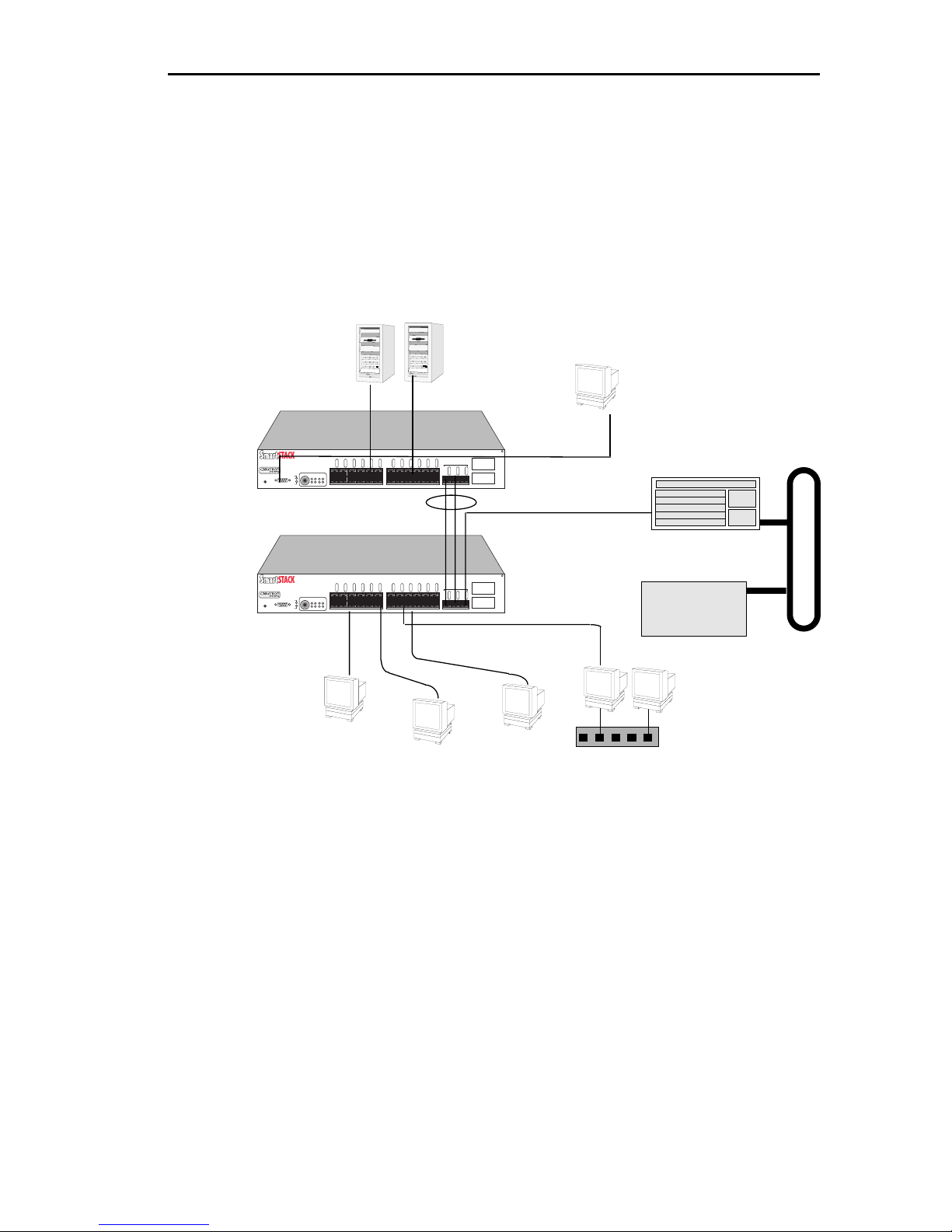
SmartSTACK Ethernet ELS10-27 Trunking
SmartSTACK Ethernet ELS10-27 supports one form of port trunking,
StackTRUNK Trunking.
SmartSTACK Ethernet ELS10-27 supports a single trunk group of up to 3
trunked ports. The group can be composed of only the 10/100 Mbps
ports. Trunked ports have the following characteristics:
¥ Learned unicast trafÞc destined to one of the trunked ports shall be
distributed evenly between all ports in the trunk group using the same
algorithm as the LynxSwitch product.
¥ Unknown addresses and broadcast/multicast trafÞc shall be
forwarded only to a single port within the trunk group according to the
trunking algorithm.
1-12
Page 29
Introduction
¥ TrafÞc received on a trunk port shall not be forwarded to any other
port in the trunk group.
The operator is able to display the trunking state on each port or
enable/disable trunking functionality on a port or a range of ports.
10BASE-T Cables
ETHERNET SWITCH
PORT STATUS MODE
STATUS
PWR
ELS10-27TX
RESET
ETHERNET SWITCH
ELS10-27TX
RESET
TX ACT FDX MON
CPU
COM
RX COL 100 USR
PORT STATUS MODE
STATUS
PWR
TX ACT FDX MON
CPU
COM
RX COL 100 USR
10BASE-T Cables
Servers
LINK
LINK
LINK
LINK
LINK
LINK
LINK
LINK
LINK
STATUS
STATUS
STATUS
STATUS
2X 4X 6X 8X 10X 12X 14X 16X 18X 20X 22X 24X
LINK
STATUS
STATUS
STATUS
STATUS
STATUS
STATUS
Trunk Lines
LINK
LINK
LINK
LINK
LINK
LINK
LINK
LINK
LINK
STATUS
STATUS
STATUS
STATUS
2X 4X 6X 8X 10X 12X 14X 16X 18X 20X 22X 24X
LINK
STATUS
STATUS
STATUS
STATUS
STATUS
STATUS
LINK
LINK
STATUS
STATUS
LINK
LINK
STATUS
STATUS
ELS10-27
EPIM100
10BASE-T/100BASE-TX
26
LINK
LINK
LINK
STATUS
STATUS
STATUS
27
25X 26X 27X
ELS10-27
EPIM100
10BASE-T/100BASE-TX
26
LINK
LINK
LINK
STATUS
STATUS
STATUS
27
25X 26X 27X
Network
Management
Station
Network Switch
WAN Router
Workgroup
Hub
Figure 1-4. SmartSTACK Ethernet ELS10-27 Backbone Configuration
1.5.6 VLANs
There are two types of VLANs that are supported by the SmartSTACK
Ethernet ELS10-27 architecture, Virtual Workgroups and 802.1Q VLANs.
Virtual Workgroups are only supported in the 802.1D mode.
Virtual Workgr oups
The SmartSTACK Ethernet ELS10-27 allows you to deÞne ports for logical
groups of associated devices (virtual workgroups) to provide a more
efÞcient ßow of trafÞc across your Ethernet network. You can deÞne a
maximum of eight virtual workgroups the number of ports within that
1-13
Page 30

Introduction
VLAN is not restricted and an individual port can be a member of
multiple Virtual Workgroups.
Note: Virtual Workgroups will only operate in 802.1D mode.
Virtual workgroups offer the ability to limit broadcasts to logical domains
within the network. Workgroup destinations are recognized by the
SmartSTACK Ethernet ELS10-27 and broadcast and unicast packets are
routed directly to hosts within the workgroup, eliminating the need to
perform a general broadcast across each segment of the network to Þnd
speciÞc host addresses.
IEEE 802.1Q VLANs
IEEE 802.1Q is a standard for virtual bridged local area networks
(VLANs). It provides an alternate method for forwarding packets
through a switch. In an 802.1D (Spanning Tree) bridge, packets are
forwarded in accordance with the spanning tree as dynamically created
by the 802.1D protocol (Bridge Protocol Data Units (BPDUs), and the
spanning tree state of each port. In 802.1Q, in addition to spanning tree,
packets are forwarded in accordance with a VLAN tag that is embedded
in the packet, and the set of ports registered for that VLAN. A set of rules
are used for ingress (receipt), forwarding, and egress (transmit).
The SmartSTACK Ethernet ELS10-27 provides support for port based
VLANs.
The ingress rules deal with the reception of tagged and untagged packets
and the decision to either drop them, or forward them to the forwarding
process.
The forwarding rules deal with forwarding packets utilizing topology
restrictions, the Þltering database, queue frames (not supported), map
priorities (not supported), and recalculation of the FCS. The
forward/Þltering database can contain three types of entries.
¥ Permanent entries
¥ Static entries
¥ Dynamic entries
Dynamic entries are created by the protocols supported by the switch
(GVRP). There will be no learning of VLANs outside of this protocol.
The egress rules deal with whether the destination port(s) are members of
the VLAN, and whether the VLAN tag is to be stripped. There is also an
1-14
Page 31

Introduction
issue of address translation on a packet that is having the VLAN tag
stripped. This only applies to multi-protocol environments, such as a
combination of Ethernet, FDDI, and Token Ring protocols and does not
apply to the SmartSTACK Ethernet ELS10-27.
802.1Q does NOT replace 802.1D but limits the relaying of packets on the
spanning tree to a subset. The subset being the members of a particular
VLAN. This is determined by comparing the VLAN ID, which is a Þeld
within the tag, to the ports which are members of that VLAN. 802.1Q
VLANs will span multiple systems and could span the entire network.
Unlike the Cabletron FN series of products where the VLAN (or Virtual
Workgroup) is limited to within a particular unit. The maximum number
of VLANs supported in 802.1Q is 32.
1.5.7 Configuration Commands
Several conÞguration parameters must be speciÞed by the user.
Manufacturing default values are supplied to allow the unit to operate in
a default (Plug and Play) conÞguration.
802.1Q Enable
The unit operates in either an 802.1D or 802.1Q mode. The mode must be
selected by the user and applies to all ports. The unit WILL NOT operate
in a mixed mode. The default is to operate in 802.1D mode.
Port Default VLAN ID
If the unit is operating in 802.1Q mode, then each port must be conÞgured
with a default port VLAN ID. The default value for each port will be the
default VLAN ID of 0x001. You are allowed to modify this on a per port
basis.
Network Management VLAN ID
If the unit is operating in 802.1Q mode a VLAN ID must be speciÞed for
each IP address conÞgured on the unit. When the network management
processor issues a response to a network management packet, it selects
the correct VLAN ID to use based on the IP subnet.
1-15
Page 32

Introduction
GVRP Enable
This indicates if the GVRP protocol is selected. If selected, the GVRP
application propagates that information to other GVRP applications.
GVRP is enabled on a per port basis.
GVRP Filter
You are able to specify a list of VLAN IDÕs that should not be dynamically
learned by GVRP. When the management processor receives a GVRP
packet, it checks this database to determine if the learning of this ID
should be restricted.
VLAN Group
You are given the ability to specify the group of ports associated with a
particular VLAN ID.
Aging Time
The aging time for 802.1D and 802.1Q mode will be the same.
Access Ports
You are able to specify which ports on the system are access ports and
always have the tags stripped.
1.6 LOCAL CONSOLE MANAGER
The Local Console Manager (LCM) is a command-line interface built into
the SmartSTACK Ethernet ELS10-27. The LCM enables you to monitor,
manage, and conÞgure the SmartSTACK Ethernet ELS10-27 through the
out-of-band RS232C connection attached to any non-intelligent terminal
or workstation running terminal emulation.
You can also use a Cabletron Systems Network Management System, or a
standard SNMP-based Network Management System, to manage the
SmartSTACK Ethernet ELS10-27. For a list of available SmartSTACK
Ethernet ELS10-27 network management tools, see Section 4.1,
SmartSTACK Ethernet ELS10-27 Management Tools.
The following sections describe LCM command syntax and the basic
LCM commands for logging in, logging out, and getting help.
1-16
Page 33

Introduction
¥ LCM commands used for conÞguring the SmartSTACK Ethernet
ELS10-27 are described in Chapter 3, Configuring Your SmartSTACK
Ethernet ELS10-27.
¥ LCM commands used for monitoring and managing the SmartSTACK
Ethernet ELS10-27 are described in Chapter 4, Monitoring and
Managing Your SmartSTACK Ethernet ELS10-27.
Note: The Getting Started with the SmartSTACK Ethernet ELS10-27
guide lists the available LCM commands, including each commandÕs
options.
1.6.1 Command Syntax Conventions
Basic LCM Commands
If you are going to manage the SmartSTACK Ethernet ELS10-27 using
LCM, you Þrst must connect the SmartSTACK Ethernet ELS10-27 to an
ASCII terminal or terminal emulator.
When you want to use LCM, begin by pressing the Enter key several
times to get the LCM prompt (ELS10-27 >).
Help
Displays the menu of available commands. Help can also be displayed by
typing a question mark (?).
Telnet support allows you to telnet to the device and gain access to LCM.
The device allows 4 sessions. Passwords for telnet are the RO and RW
community names for the device and allow the corresponding level of
access. You are not allowed to modify passwords via a Telnet session. If
an IP address is added or modiÞed using Telnet, the new address will not
take affect until the next reboot.
Erase
Entering erase to erase the current SmartSTACK Ethernet ELS10-27
conÞguration returns all parameters to the default values.
1-17
Page 34

Introduction
Exit or Logout
This command logs you out of LCM. (The exit command is functionally
equivalent to the logout command.)
Traplog
Traplog displays the traps messages captured by the SmartSTACK
Ethernet ELS10-27. The following is an example of a traplog display:
ELS10-27TX> traplog
Trap 16 0:00:00
The unit has booted.
Trap 25 0:00:00
The unit’s spanning tree maximum age has changed.
Trap 26 0:00:00
The unit’s spanning tree hello time has changed.
Trap 27 0:00:00
The unit’s spanning tree forward delay times has changed.
Trap 3 0:00:02 port 1
The current functional state of the port has changed.
...
ELS10-27TX>
Figure 1-5. Traplog display
1-18
Page 35

Introduction
The following conventions apply as you use LCM commands:
¥ Press the Enter key to execute a command after you type it in.
¥A port range is either a single port number, or a list of port numbers
separated by commas or hyphens. For example, 3 is port 3; 3,7 are
ports 3 and 7; 3-5 are ports 3,4, and 5; and 3-5,7 are ports 3,4,5, and
7.
¥ To quit any command, press the Control-C keys (^C or Ctrl-C).
¥ You can abbreviate any command where there is no ambiguity; if there
is ambiguity, LCM responds with an error message.
¥ Commands are not case sensitive.
¥ Any invalid commands or misspellings will receive an error message.
¥ A previous command can be repeated by typing !!
¥ MAC addresses are displayed in little-endian Ethernet (least
signiÞcant bit) bit order, with each octet separated by a colon. For
example:
ELS10-27 >address 00:40:27:04:1a:0f
¥ Information that is optional with an LCM command is enclosed in
square brackets [ ].
ELS10-27 >ipaddr 192.138.217.40
¥ Parameters that appear in all capital letters, for example bridge [PORT-
RANGE]
, indicate that you must enter a value for that parameter. If a
string of parameters is displayed between braces, for example
[{off|on|noBPDU}], you must select one of the displayed options. For
example, if you wanted to enable bridging on a port, or a range of
ports, you would enter:
ELS10-27 >bridge 2-4 on
1-19
Page 36

Introduction
LCM Command Summary
help or ? Display this menu
addresses display [any] [ADDR [MASK]] to display learned addresses
arp display to display the ARP table
baud [BAUD-RATE] to change the console baud rate
bridge [PORT-RANGE [OPTIONS] to set bridging methods
community to change the password/community
disable [? for syntax] to disable a set of ports
enable [? for syntax] to enable a set of ports
erase to erase conÞguration
exit or logout to logout
ident to display unit identiÞcation
igmp [on | off] to enable IPM Þltering by snooping IGMP
ipaddr [IPADDR [MASK]] to set or display IP addresses
ipmÞlter [? for syntax] to statically Þlter out ports
ipmrouter {add | delete} PORT-RANGE to set or display IP Multicast Router ports
kill {session-number} to kill a session (console use only)
mirror [? for syntax] to set or display port mirroring
ping [-rvsx] HOST [DATASIZE [COUNT]] send ICMP ECHO_REQUEST pkts
port [? for syntax] to set or display port parameters
query [on |off] [name] to act as an IGMP Querier
reboot [? for syntax] to reboot the unit after SECONDS
route [? for syntax] to display routing table information
session to display current LCM sessions
switch [? for syntax] to set or display switch parameters
status[PORT-RANGE/clear PORT-RANGE] to display unit or port status
sttimer [TIMER-VALUE] to set or display st age time
traceroute [? for syntax] to print the route taken to a host
trapcontrol [on | off] to set or display traps control value
traplog to display the most recent SNMP traps
trunk [? for syntax] to set display trunking status
vlan [? for syntax] to conÞgure IEEE Vlans
workgroup [? for syntax] to set or display workgroups
1-20
Page 37

Introduction
If a line contains the text Ò[? for syntax]Ó one of the following displays will detail the
syntax.
additional command syntax:
switch [802.1d | 802.1Q]
cut[-through] | store[-and-forward]
[back[pressure] {on | off}]
enable [PORT-RANGE [RIP]] [TransmitPacing]]]
port [PORT-RANGE [speed {auto | 10[Mbps] | 100[Mbps]}]
[duplex {auto | full[-duplex] | half[-duplex]}]
[storm THRESHOLD TIME-INTERVAL]
[vlan {name |VLAN-ID}]
[802.3x [ßow control] {on | off}]
[GVRP {On | off}]
[access {add | del[ete]}]]
reboot [SECONDS [down[load]] | off]
[par[ameters] PATH [IP-ADDR [GATEWAY-ADDR]]]
route [add | del GATEWAY-ADDR]
[display [IPADDR]]
traceroute [-m MAX_HOPS][-q NQUERIES][-w WAIT] HOST_IP [DATA_SIZE]
vlan [add PORT-RANGE NAME VLAN-ID [IP-ADDR] [MASK]]
[del[ete] PORT_RANGE NAME VLAN-ID]
[res[trict] {add | de[lete]} PORT-RANGE VLAN-ID]
ipmulticast [add | del[ete] IPMADDR PORT-RANGE IPMADDR]
mirror [port {add | del[ete]} SRC-PORT DEST-PORT]
[address]{add | del[ete]} MAC-ADDRESS DEST-PORT]
[on | off]
ipmÞlter [add IPMADDR PORT-RANGE]
[del[ete] IPMADDR]]
[on | off]
trunk [add PORT-RANGE]
[del[ete] PORT-RANGE]
workgroup [NAME [{del[ete] | PORT_RANGE [INFO]]}]
1-21
Page 38

Introduction
Status
When the status command alone is typed, the following is displayed:
ELS10-27> status
Software Currently Running: Version 1.00.00 Mon 1/15/99--14:49:29
Next Bootstrap: Version 1.00.00 Mon 1/15/99--14:49:29
Power-up test failures: none
System Up Time: 4 weeks 3 days, 16:49:20
Current Number of Learned Addresses: 76
CPU utilization is heavy
Port RX Packets TX Packets Collisions Erred Packets
1 0 0 0 0
2 200771 170540573 11057 18756
3 160310185 260185705 1550454 2597695
4 0 220670886 0 0
5 0 0 0 0
6 0 0 0 0
7 879974 226060879 29462 59569
8 6367594 225306752 59103 122763
9 0 0 0 0
10 0 220670886 0 0
11 75924 214287698 76 1059
12 1963079 228024703 147751 252280
Type <CR> to continue the display... >
This is repeated by the remainder of the ports on the system, followed by
a display for each individual port as follows.
Port 1 Status
Type/Speed: 10B-TPX/10 Mbpss
VLAN ID Blue 0x001
1-22
Page 39

Introduction
GVRP Enabled
Port Mirroring: No
Duplex Mode: Half Duplex
Bridging: Transparent Bridging
Enabled/Disabled: Enabled, Rip listening, port w/o link
Spanning Tree: Without link
Trunking State: Off
Pkts Transmitted: 0
Pkts Received: 0
Carrier Losses: 0
Total Collisions: 0
Excess Collisions: 0
RX Filtered Pkts: 0
RX Runt Pkts: 0
RX FCS/Align Errs: 0
Internal TX Errs: 0
Type <CR> to display port 2 status ... >
If the status command is issued followed by a port number the following
is displayed. If a port range is speciÞed, all ports in the range are
displayed.
ELS10-27> status 2
Port 2 Status
Type/Speed: 10B-TPX/10 Mbps
VLAN ID Account 0x001
GVRP Disabled
Port Mirroring: No
Duplex Mode: Half Duplex
Bridging: Transparent Bridging
Enabled/Disabled: Enabled, Rip listening
Spanning Tree: Forwarding
Trunking State: Off
Pkts Transmitted: 170646338
Pkts Received: 200806
1-23
Page 40

Introduction
Carrier Losses: 0
Total Collisions: 11057
Excess Collisions: 0
RX Filtered Pkts: 523
RX Runt Pkts: 0
RX FCS/Align Errs: 0
Internal TX Errs: 11057
Enable
If the enable command is typed without any parameters, the following is
displayed. It does not enable any of the ports.
ELS10-27> enable
Usage: enable [PORT-RANGE [RIP] [TransmitPacing]]
Port 1: Enabled, port w/o link
Port 2: Enabled, port w/o link
Port 3: Enabled
Port 4: Enabled, port w/o link
Port 5: Enabled, port w/o link
Port 6: Enabled, port w/o link
Port 7: Enabled
Port 8: Enabled
Port 9: Enabled, port w/o link
Port 10: Enabled
Port 11: Enabled
Port 12: Enabled
Type <CR> to continue the display... >
To enable a port or group of ports, the command is followed by the
port(s) and any options desired. The following is displayed:
ELS10-27> enable 2-4
Enabling port 2
Enabling port 3
Enabling port 4
By default all ports are enabled.
1-24
Page 41

Introduction
Disable
If the disable command is entered without any port(s) speciÞed, the
display reports the state of all of the ports. It does not disable any of the
ports.
ELS10-27> disable
Usage: disable [PORT-RANGE]
Port 1: Enabled, Rip listening, port w/o link
Port 2: Enabled, Rip listening
Port 3: Enabled
Port 4: Enabled
Port 5: Enabled, port w/o link
Port 6: Enabled, port w/o link
Port 7: Enabled
Port 8: Enabled
Port 9: Enabled, port w/o link
Port 10: Enabled
Port 11: Enabled
Port 12: Enabled
Type <CR> to continue the display... >
If a port range is included, the following is displayed and the ports are
disabled.
ELS10-27> disable 5-6
Port 5: Disabled
Port 6: Disabled
Switch
The switch command,
switch [802.1d | 802.1Q]
allows you to select the mode in which the ELS10-27 operates. The two
modes are 802.1D (spanning tree) or 802.1Q (spanning tree with IEEE
VLANs). In addition, you can select cut through or store and forward,
[cut[-through] | store[-and-forward]]
[back[pressure] {on | off}]
1-25
Page 42

Introduction
and select to use back pressure as a means of ßow control. The default
settings are:
802.1d mode
store-and-forward
Backpressure off
The command by itself displays the following:
ELS10-27>switch
The present switch mode is: 802.1d
The switch mode upon the next reboot will be: 802.1d
The forwarding mode in use is: Store and Forward
Backpressure is off
Port
The Port command,
port [PORT-RANGE [speed {auto | 10[Mbps] | 100[Mbps]}]
[duplex [{auto | full[-duplex] | half[-duplex]}]]
[storm THRESHOLD TIME-INTERVAL]
[vlan {name |VLAN-ID}]
[802.3x [ßow control] {on | off}]
[GVRP {On | off}]
[access
allows you to conÞgure the port(s) on the unit in regards to speed, duplex
mode, broadcast storm protection values and default VLAN ID used on
each port. You are not allowed to name the VLAN here. Refer to the vlan
command to name a vlan. By setting the default VLAN ID for a port, the
port WILL NOT automatically become a member of that VLAN. The
VLAN must be created Þrst using the VLAN command and this port
made a member. Likewise, if the default VLAN ID is changed, the port is
not removed from the old VLAN, you must use the VLAN command and
remove the port from the VLAN. In addition, you are able to specify if
GVRP is enabled for these ports. If enabled, GVRP messages are received
on these ports and GVRP messages are propagated to these ports.
{add | del[ete]}]]
1-26
Page 43

Introduction
The access option speciÞes when operating in 802.1Q mode, that these
ports act as access ports. All devices attached to this segment are non-tag
aware devices, Therefore, all tags are stripped on egress, and the default
tag is always added on ingress. In addition, the Þrmware creates
additional address database entries when needed to ensure connectivity
without ßooding.
Entering the port command by itself displays the following:
ELS10-27>port
Port Speed
1 10 Full 600000 100 0x001 Default yes Enabled yes
2 10 Full 600000 100 0x001 Default yes Disabled no
3 10 Full 600000 100 0x001 Default yes Enabled no
4 10 Full 600000 100 0x001 Default yes Enabled no
5 10 Half 600000 100 0x001 Default yes Enabled no
6 10 Full 600000 100 0x001 Default no Enabled no
7 10 Full 600000 100 0x001 Default yes Enabled no
8 10 Full 600000 100 0x001 Default yes Enabled no
9 10 Full 600000 100 0x001 Default yes Enabled no
10 10 Half 600000 100 0x001 Green yes Enabled no
11 10 Full 600000 100 0x001 Default no Enabled no
12 10 Full 600000 100 0x001 Default no Enabled no
Duplex
Mode
Storm
Threshold
Storm
Time
Default
VLAN-ID
VLAN
Name
Flow Ctl GVRP
Access
Port
Type <CR> to continue the display ... >
The default setting is auto. To change the speed on a group of ports, enter
the following:
ELS10-27>port 25-27 speed 10
Port 25 is 10 Mbps Ethernet
Port 26 is 10 Mbps Ethernet
Port 27 is 10 Mbps Ethernet
Similarly, to set the duplex mode on a group of ports, enter the following:
ELS10-27>port 25-27 duplex auto
Port 25 is using Auto Negotiation Mode.
Port 26 is using Auto Negotiation Mode.
Port 27 is using Auto Negotiation Mode.
1-27
Page 44

Introduction
To set the storm protection, enter the following:
ELS10-27>port 1 storm 100000 10
port 1 threshold = 100000,
interval = 10
To set the default VLAN ID the following would be entered. In 802.1Q
mode, the factory default would be a value of 0x001 on every port.
ELS10-27>port 5 vlan 0x003
port 5 vlan id = 0x003
Commands cannot be combined. The following is not allowed.
port 2-4 duplex half storm 100000 10
Community
For security reasons, you are allowed to set a community name. This is
similar to a password. Without the password, you are limited in what you
are allowed to do. To set a new community name, type community.
ELS10-27>community
You are prompted for the old community name, then the new name and
conÞrmation of the new name. The default name is ÔpublicÕ.
Old community name>
New community name>
Verify community name>
Ident
The Ident command identiÞes the unit in terms of part number. The Þrst
part number displayed is for the ELS10-27 itself, the second part number
is for an optional plug-in module. Following this, any Power-up test code
and Diagnostic data is displayed. Finally, a list of information related to
BootP parameters and the code image conÞgured to be downloaded is
displayed.
ELS10-27> id
Part Number: 9401911000 973700030748
Power-up test code: 00000000
1-28
Page 45

Diagnostic data: 00000000 00000000 00000000 00000000 00000000
00000000 00000000 00000000
Last Image File name /etc/bootp/els10-27
Last Server IP Address 192.68.37.1
Flash Size 0x200000
Boot Revision 01.00.02
Operational Status Normal Operation
Exit or Logout
Either of these commands logs you out of LCM.
Erase
Introduction
The erase command allows you to erase all of the conÞguration material
and restore the factory defaults to the unit. As a safety mechanism you are
prompted to conÞrm the command. The entire word ÔyesÕ must be typed.
By entering the erase command, the following is displayed.
ELS10-27>erase
This erases all conÞguration information and return the unit to factory
defaults on the next system reset.
Continue? [yes | {no | CR} ]
If anything other than ÔyesÕ is entered the command will be canceled.
Reboot
The reboot command allows you to force a system reboot either
immediately or to schedule it for some later time. In the event that it was
scheduled, the user can prevent the system from rebooting by entering
the reboot command with the optional parameter ÔoffÕ. Additionally,
several optional parameters can be used.
The ÔdownloadÕ parameter speciÞes not only for the system to reboot, but
to also obtain a new code image from the network. In the event that a
download is desired, you can specify the necessary parameters or can use
parameters obtained via the BootP process. The parameters are the path
and Þle name to be used on the TFTP server, the IP Address of the server
and a gateway IP Address in the event that the server is not directly
accessible.
1-29
Page 46

Introduction
reboot [SECONDS [down[load]] | off]
[par[ameters] PATH [IP-ADDR [GATEWAY-ADDR]]]
If you enter a reboot command, the following is displayed:
ELS10-27>reboot 300
Re-boot pending in 300 seconds
If you then follow this with the reboot ÔoffÕ command within 300 seconds,
the following is displayed:
ELS10-27>reboot off
No re-boot pending
Address Display
The address display command displays the MAC addresses, whether the
address has been learned, the port the address is known on, and how old
the address entry is. In 802.1Q mode, the following is displayed. If the
unit was operating in 802.1D mode, the VLAN ID and VLAN Name are
not displayed.
ELS10-27> address display
Address Type Port Age(secs) VLAN ID VLAN Name
00:40:27:00:55:bf Learned 26 1 0x003 Blue
00:40:27:00:58:17 Learned 26 14 0x003 Blue
00:00:0c:19:ce:35 Learned 26 4 0x003 Blue
00:80:cf:00:02:b7 Learned 26 215 0x003 Blue
00:00:c0:d8:f2:9a Learned 26 80 0x002 Green
00:40:27:07:b4:9d Learned 26 134 0x003 Blue
00:00:c0:b7:08:0e Learned 26 10 0x003 Blue
08:00:20:79:fb:df Learned 17 1 0x005 Green
00:00:1d:1d:63:3c Learned 26 0 0x003 Blue
00:00:86:09:99:31 Learned 26 8 0x003 Blue
08:00:20:0f:ca:03 Learned 26 53 0x005 Green
08:00:20:7b:d5:58 Learned 26 223 0x003 Blue
1-30
Page 47

Introduction
08:00:20:72:0b:1d Learned 26 55 0x003 Blue
08:00:09:56:01:fe Learned 26 18 0x003 Blue
00:00:c0:aa:08:0e Learned 16 10 0x002 Green
00:04:ac:26:bd:8b Learned 26 170 0x003 Blue
08:00:69:07:19:a8 Learned 26 24 0x003 Blue
00:a0:c9:37:eb:17 Learned 26 130 0x005 Green
00:00:1d:1a:80:d7 Learned 26 0 0x003 Blue
00:00:c0:1a:7a:0e Learned 26 143 0x003 Blue
Enter <CR> to continue, Cntl-C to exit:
Optionally, you can specify the ÔanyÕ option. This will also display any
permanent addresses that are conÞgured and any entries that have been
created for Þltering.
ELS10-27> address display any
Address Type Port Age(secs)
01:80:c2:00:00:00 BPDU ** 2760312
01:80:c2:00:00:01 Reserved ** 2760312
01:80:c2:00:00:02 Reserved ** 2760312
01:80:c2:00:00:03 Reserved ** 2760312
01:80:c2:00:00:04 Reserved ** 2760312
01:80:c2:00:00:05 Reserved ** 2760312
01:80:c2:00:00:06 Reserved ** 2760312
01:80:c2:00:00:07 Reserved ** 2760312
01:80:c2:00:00:08 Reserved ** 2760312
01:80:c2:00:00:09 Reserved ** 2760312
01:80:c2:00:00:0a Reserved ** 2760312
01:80:c2:00:00:0b Reserved ** 2760312
01:80:c2:00:00:0c Reserved ** 2760312
01:80:c2:00:00:0d Reserved ** 2760312
1-31
Page 48

Introduction
01:80:c2:00:00:0e Reserved ** 2760312
01:80:c2:00:00:0f Reserved ** 2760312
01:80:c2:00:00:10 All LANs ** 2760312
01:40:27:00:54:72 Reserved ** 2760312
00:00:1d:66:88:4e Port 1 2760312
01:00:0e:00:00:01 Filter ** 5767
Enter <CR> to continue, Cntl-C to exit:
If desired, you can specify a MAC address to be searched for and
optionally a mask.
ELS10-27> address display 08:00:20:79:fb:df
Address Type Port Age(secs)
08:00:20:79:fb:df Learned 17 0
Bridge
The bridge command allows you to specify whether transparent bridging
(Spanning Tree) should be enabled on a per port basis. If only the bridge
command is speciÞed, the following is displayed:
ELS10-27> bridge
Usage: bridge [PORT-RANGE [{off | on | noBPDU}]]
Port 1 bridging: Transparent Bridging
Port 2 bridging: Transparent Bridging
Port 3 bridging: Transparent Bridging
Port 4 bridging: Transparent Bridging
Port 5 bridging: Transparent Bridging
Port 6 bridging: Transparent Bridging
Port 7 bridging: Transparent Bridging
Port 8 bridging: Transparent Bridging
Port 9 bridging: Transparent Bridging
1-32
Page 49

Introduction
Port 10 bridging: Transparent Bridging
Port 11 bridging: Transparent Bridging
Port 12 bridging: Transparent Bridging
Type <CR> to continue the display ... >
Optionally, you can select to turn transparent bridging off, or not to send
BPDUs out of a group of ports.
ELS10-27> bridge 9-10 off
Port 9 bridging: Off
Port 10 bridging: Off
ELS10-27> bridge 9-10 nobpdu
Port 9 bridging: Transparent Bridging, BPDUs suppressed
Port 10 bridging: Transparent Bridging, BPDUs suppressed
STTimer
The STTimer (Spanning Tree Timer) command allows you to set the aging
period for learned addresses under spanning tree. The default is 300
seconds. The command alone will display the present conÞgured value.
ELS10-27> sttimer
Spanning Tree Age Time: 300 seconds
Baud
The baud command allows you to specify the bit transfer rate used on the
local communications port. The default value is 9600, and valid values
range from 2400 to 19200. When the command alone is typed the
conÞgured value is displayed.
ELS10-27> baud
Usage: baud [2400 | 4800 | 9600 | 19200]
Baud rate is 9600.
1-33
Page 50

Introduction
Ipaddr
The Ipaddr (IP Address) command is used to conÞgure an IP address for
the unit. Optionally, a gateway address is conÞgured to act as a default
path in the event that a path to the peer cannot be determined. Refer to
the Route Command to conÞgure a gateway.
ipaddr [IPADDR [MASK] | [vlan id | vlan name]]
In 802.1D mode only one IP address can be conÞgured on the unit. Access
can be gained to the unit from any port using that one IP address.
In 802.1Q mode multiple IP addresses can be conÞgured in order to
access the unit from multiple VLANs. (The VLAN command is used to
conÞgure an IP address on a VLAN.)
If only the ipaddr command is entered, the following display is seen:
ELS10-27> ipaddr
IP Address Address Mask VLAN ID VLAN Name
134.141.110.27 255.255.0.0 0x005 Blue
192.167.38.25 255.255.0.0 0x007 Payroll
Type <CR> to continue the display ... >
If a VLAN ID or VLAN Name is entered, the display is restricted to the
relevant entries.
Arp
The arp command allows ARP entries to be displayed. Static ARP entries
CANNOT be conÞgured.
ELS10-27> arp
Port MAC Address IP Address Type
26 00:00:1d:1d:63:3c 134.141.5.126 Dynamic
26 00:40:27:00:bb:14 134.141.109.18 Dynamic
1-34
Page 51

Introduction
Route
The route command allows you to display routing entries. Only one static
route entry can be conÞgured; the default gateway.
route display [IPADDR][[GATE[WAY-ADDR]] IPADDR]
ELS10-27> route
Gateway 134.141.110.14
Destination Next Hop Net Mask Protocol VLAN ID
000.000.000.000 134.141.109.018 255.000.000.000 rip 0X001
100.000.000.000 134.141.105.153 255.000.000.000 rip 0X001
101.000.000.000 134.141.105.155 255.000.00000.0 rip 0X001
102.000.000.000 134.141.105.153 255.000.000.000 rip 0X001
103.000.000.000 134.141.105.154 255.000.000.000 rip 0X001
134.141.000.000 000.000.000.000 255.255.000.000 local 0X001
134.141.110.027 134.141.110.027 255.255.255.255 local 0X001
134.142.000.000 134.141.105.014 255.255.000.000 rip 0X001
172.017.000.000 134.141.075.180 255.255.000.000 rip 0X001
192.168.037.000 134.141.109.018 255.255.255.000 rip 0X001
192.168.038.000 134.141.110.004 255.255.255.000 rip 0X001
198.113.121.000 134.141.110.004 255.255.255.000 rip 0X001
200.200.205.000 134.141.105.153 255.255.255.000 rip 0X001
201.201.209.000 134.141.105.153 255.255.255.000 rip 0X001
202.202.204.000 134.141.105.154 255.255.255.000 rip 0X001
203.203.208.000 134.141.105.154 255.255.255.000 rip 0X001
203.203.209.000 134.141.105.154 255.255.255.000 rip 0X001
204.204.212.000 134.141.105.154 255.255.255.000 rip 0X001
Type <CR> to continue the display ... >
1-35
Page 52

Introduction
Ping
The ping command allows you to attempt to contact a device using a
particular IP address. The HOST parameter is actually an IP Address.
Host name to IP address mapping is not available. The command
operates in a manner similar to the ping command on an UNIX operating
system and is useful in determining connectivity in the network.
ping [-rvsx] HOST [DATASIZE [COUNT]]
If the command alone is entered the usage statement is displayed.
Usage: ping [-rvsx] host [datasize [count]]
-r = record route
-v = verbose
-s = send one packet per second continuously
-x = send packets continuously w/o delay
An example of a ping command and the resulting output is as follows:
ELS10-27> ping -s 192.168.37.1
PING 192.168.37.1: 56 data bytes
56 bytes from 192.168.37.1 icmp_seq=1 time=99 ms
56 bytes from 192.168.37.1 icmp_seq=2 time=9 ms
56 bytes from 192.168.37.1 icmp_seq=3 time=102 ms
56 bytes from 192.168.37.1 icmp_seq=4 time=9 ms
56 bytes from 192.168.37.1 icmp_seq=5 time=103 ms
56 bytes from 192.168.37.1 icmp_seq=6 time=102 ms
----192.168.37.1 PING Statistics----
7 packets transmitted, 6 packets received, 14% packet loss
Traceroute
The traceroute command is a handy debugging tool used to determine a
path taken from the ELS10-27 to another device using its IP address. You
are allowed to specify several options. The MAX_HOPS allows you to
specify the maximum time that a packet is allowed to live in the network
before being discarded. The next option speciÞes the number of queries
that should be used, followed by the length of time to wait for a reply.
1-36
Page 53

Introduction
When the traceroute command itself is used, the usage statement is
displayed.
ELS10-27>traceroute ?
traceroute [-m max_hops] [-q nqueries] [-w wait] host_ip [data_size]
The following is a sample traceroute:
ELS10-27> traceroute 192.168.37.20
traceroute to (192.168.37.20), 30 hops max, 40 byte packets
1 134.141.109.18 6 ms 91 ms 99 ms
2 192.168.37.20 99 ms 99 ms 99 ms
Traplog
Various SNMP traps are sent to an SNMP Manager from the ELS10-27
when certain events occur. The last 50 of these traps are kept in a log
within the ELS10-27 and can be displayed to assist in isolating failures.
The command entered by itself displays the traplog.
ELS10-27> traplog
Trap 20 4 weeks 4 days, 0:19:00
The spanning tree topology has stopped changing.
Trap 19 4 weeks 4 days, 0:17:58
The spanning tree topology has begun to change.
Trap 32 4 weeks 4 days, 0:05:18 port 13
The spanning tree state of the port has changed.
Trap 3 4 weeks 4 days, 0:05:18 port 13
The current functional state of the port has changed.
Trap 20 4 weeks 3 days, 23:47:57
The spanning tree topology has stopped changing.
Trap 19 4 weeks 3 days, 23:46:54
The spanning tree topology has begun to change.
Trap 32 4 weeks 3 days, 23:41:41 port 15
The spanning tree state of the port has changed.
Trap 32 4 weeks 3 days, 23:41:36 port 15
The spanning tree state of the port has changed.
1-37
Page 54

Introduction
Trap 3 4 weeks 3 days, 23:41:36 port 15
The current functional state of the port has changed.
Trap 32 4 weeks 3 days, 23:39:36 port 15
The spanning tree state of the port has changed.
Type <CR> to continue, Cntl-C to exit...>
VLAN
The VLAN command, when operating in 802.1Q mode, allows you to
specify an IEEE 802.1Q VLAN. You must specify a VLAN ID, and a name
to associate with that ID. If you want to manage this unit on this VLAN
you must also assign an IP Address.
vlan [add PORT-RANGE NAME VLAN-ID [IP ADDR] [[IP MASK]]
[del[ete] PORT-RANGE {NAME |VLAN-ID}]
[res[trict] {add | de[lete]} PORT-RANGE VLAN-ID]
If the command alone is speciÞed, the existing VLANs are displayed. Two
types of VLANs are displayed; the static entries that have been created by
this command, and dynamic entries which have been learned by the
switch via GVRP.
ELS10-27>vlan
VLAN-ID NAME TYPE IP Addr IP MASK PORTS
0x001 default STATIC 10.2.7.225 255.0.0.0 1-27
By using the VLAN command, the default VLAN ID for the port WILL
NOT be changed. Refer to the port command to change the default VLAN
ID for a port.
If the restriction option is speciÞed, the switch will not allow a VLAN to
be established for that ID from either a user interface or GVRP.
Workgroup
The workgroup command allows you to group ports together to limit the
scope of broadcast, multicast and unicast packets. If there are no user
deÞned workgroups, one default group exists consisting of all ports. As
workgroups become deÞned, ports are removed from the default group
and added to the newly deÞned group.
1-38
Page 55

Introduction
Note: Workgroups are only valid in 802.1D mode.
ELS10-27> workgroup [NAME [del[ete] | PORT_RANGE]]
To display all of the present workgroups, simply enter the command.
ELS10-27>workgroup
Name: default
Port: 8,10,13-27
Name: lab_e
Port: 9,12
Name: lab_a
Port: 9,11
To display a particular workgroup specify the name.
ELS10-27>workgroup lab_a
Name: lab_a
Port: 9,11
IGMP
You can enter the following command to enable or disable IGMP
snooping on the ELS10-27 device. If IGMP snooping is enabled, the
ELS10-27 will restrict IP Multicast packets to members of each IP
Multicast group. The command syntax is:
IGMP [on | off]
You can display the status of IGMP snooping by entering the command
alone.
ELS10-27> IGMP
IGMP Þltering on
When IGMP snooping is disabled after being enabled, all Þltering
databases are deleted. Router port lists and the status of Querying on the
device are re-initialized. The factory default for IGMP Þltering is on.
1-39
Page 56

Introduction
IPMRouter
You can enter the following command to specify the ports to be included
in all IP Multicast Þlters. These are expected IGMP Router ports that
would be sending IGMP Queries. The command is also used to add nonIGMP capable ports so that they would also be included in all the Þlters.
Once you statically conÞgure the IP Multicast Router ports, any queries
that are heard from the network are merged into the router port list.
ELS10-27> ipmrouter {add | delete} PORT-RANGE
If you re-enter the command with a different PORT-RANGE, the
databases are ßushed and all Þlters are re-learned.
ELS10-27> ipmrouter add PORT-RANGE
To delete some or all of the routers included in all Þlters, you enter:
ELS10-27> ipmrouter delete PORT-RANGE
All the Dynamic database entries are ßushed and all the Þlters re-learned.
The command by itself displays the existing list of ports.
ELS10-27>ipmrouter
IP Multicast Routing ports - 1, 5, 6, 9, 23-27
Ipmulticast
Use the following command to create an IP Multicast group:
ELS10-27> ipmulticast [{add | del[ete] IPMADDR PORT-RANGE IPMADDR}]
Create an IP multicast group by entering the IP Group Address along
with a list of ports. Enter the following command to statically conÞgure
an IP Multicast group. Once a group is conÞgured, any information the
Þrmware has learned dynamically, will not alter the static conÞguration.
Re-enter the command to add to, or change the list of ports in the group.
ELS10-27> ipmulticast add PORT-RANGE IPMADDR
Enter the following command to delete an IP Multicast group:
ELS10-27> ipmulticast del[ete] IPMADDR
1-40
Page 57

Introduction
Display the state of Dynamic IP Multicast Filtering and all the IP
Multicast Group entries by entering the command by itself.
ELS10-27> ipmulticast
Dynamic IP Multicast Þltering is ON
GroupAddress Ports Class
224.0.0.1 1-27 Permanent
224.0.0.9 2-8,23 Static
224.0.0.200 1-27 Dynamic
Ipmfilter
The ipmÞlter command is used to Þlter IP Multicast packets from a
particular port. It is also used to enable or disable static IP Multicast Þlter
groups created with the ipmÞlter command.
ELS10-27> ipmÞlter [on | off]
[{add | del[ete]} PORT-RANGE IPMADDR]
Enter the following command to specify ports NOT to be included in
Þlters for an IP Multicast Group. Once a Þlter is in place, the port WILL
NOT transmit packets for that group, even if a host attached to that port
attempts to join the group.
ELS10-27> ipmÞlter add PORT-RANGE IPMADDR
Re-enter the command to add to or change the list of ports in the group.
Add or change the Þlters for an IP Multicast group by entering:
ELS10-27> ipmÞlter add PORT-RANGE IPMADDR
Remove Þlters from an IP Multicast group by entering:
ELS10-27> ipmÞlter del[ete] IPMADDR
Enter the following command to allow the Þrmware to examine IP
Multicast UDP trafÞc and dynamically set up port Þlters to restrict trafÞc
to speciÞc ports.
ELS10-27> ipmÞlter on
The default for ipm Þlter command is off.
Display the IP Þlters by entering:
ELS10-27> ipmÞlter
1-41
Page 58

Introduction
IP Multicast Þltering is ON
GroupAddress Ports
224.0.0.24 1-27
224.0.0.9 5
224.0.0.200 1, 9, 13
Query
Use the following command to enable or disable the device to act as a
querier. In an 802.1D Workgroup environment, you may specify the name
of the workgroup on which to initiate IGMP Queries.
ELS10-27>Query [on | off] [wgname]
To enable a querier on a workgroup named blue, the following command
is issued:
ELS10-27>Query on blue
To display the state of IGMP Querying on the device or to list the
segments that we are sending Queries on, you can enter:
ELS10-27> Query
IGMP Query on Default Group
IGMP Query on Blue
IGMP Query on Accounting
The factory default for the system to initiate IGMP Query packets is off.
If you change the state, the databases are ßushed and all the Þlters relearned.
Mirror
The mirror command has two forms. One allows you to mirror all
inbound and outbound trafÞc from one port to another. The second
allows all packets with speciÞc destination MAC addresses to be
mirrored to a particular port. Up to four destination MAC addresses may
be mirrored simultaneously.
mirror [port {add | del[ete]} SRC-PORT DEST-PORT]
[add[ress]{add | del[ete]} MAC-ADDRESS DEST-PORT]
[on | off]
1-42
Page 59

Introduction
By entering the command alone, the present mirror selections are
displayed.
ELS10-27>mirror
port 5 is being mirrored to port 25.
ELS10-27>mirror
The mirror port is 7
02:98:10:03:10:09
98:45:82:94:54:76
Trunk
The command has the following format:
ELS10-27>trunk [PORT-RANGE {on | off}]
You are able to enable/disable trunking functionality on a port or a range
of ports.
For example:
ELS10-27> trunk 25-27 on
The above command turns on trunking on ports 25 through 27.
Note: Trunking is only allowed on ports 25-27.
Session
The session command displays the number of active sessions, the session
number assigned, the amount of idle time, and the origin of the session.
The display appears as:
Session Idle Time Origin
0 0:00 Console
1 0:09 10.2.10.161
Kill
The kill command relates to Telnet sessions. You are allowed to kill any of
the Telnet session. You are not able to kill the Console session. To kill a
session, issue the kill command followed by the session number.
kill 1
1-43
Page 60

Introduction
Trap control
Trap control gives you the ability to allow all traps or to disallow all traps.
SNMP MIB variables are available to disable a particular trap, or all traps
of a particular severity. The default for trap control is ÒdisabledÓ.
Telnet
Telnet support allows you to telnet to the device and gain access to LCM.
The device allows 4 sessions. Passwords for telnet are the RO and RW
community names for the device and allow the corresponding level of
access. You are not allowed to modify passwords via a Telnet session. If
an IP address is added or modiÞed using Telnet, the new address will not
take affect until the next reboot.
1-44
Page 61

CHAPTER 2
UNPACKING AND INSTALLING
YOUR SMARTSTACK ETHERNET ELS10-27
Only qualified personnel should perform installation
procedures.
Carefully unpack the SmartSTACK Ethernet ELS10-27 from the shipping
carton and inspect it for possible damage. If any damage is evident,
contact your supplier. The shipping carton contains the following:
¥ The SmartSTACK Ethernet ELS10-27 unit
¥ One AC power cord
¥ Console Cable kit
¥ Two rack-mounting brackets with fasteners (for rack-mount
installation)
¥ Documentation Ð In addition to this manual, Release Notes are also
included.
2-1
Page 62
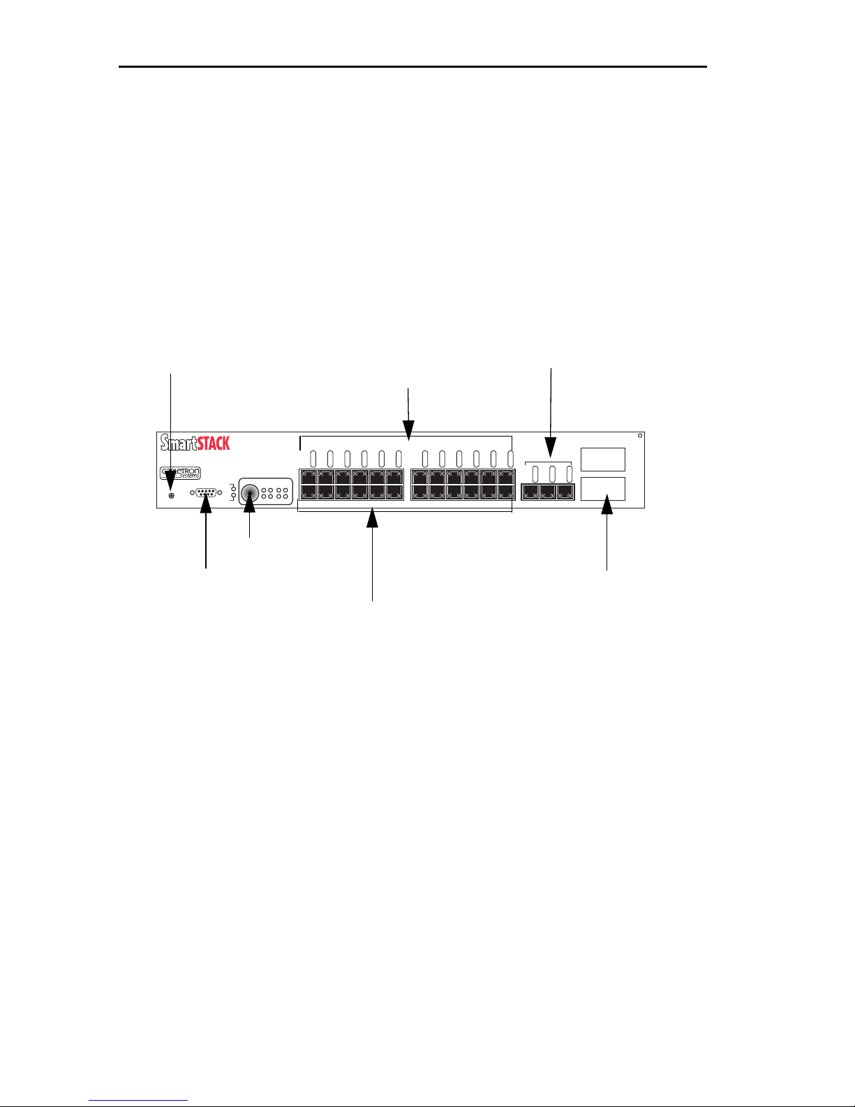
Unpacking and Installing Your SmartSTACK Ethernet ELS10-27
2.1 SMARTSTACK ETHERNET ELS10-27 FRONT PANEL
The SmartSTACK Ethernet ELS10-27 provides 27 RJ45 ports supporting
24 autonegotiating 10 Mbps ports and 3 autonegotiating 10/100 Mbps
ports.The device also features two EPIM-100 slots that allow you to install
up to two EPIM-100s to provide multimode Þber uplinks (with potential
for single mode Þber). Figure 2-1 shows the front panel of the
SmartSTACK Ethernet ELS10-27. The LEDs and buttons are described in
Tables 2-1 and 2-2.
100BASE Ethernet Ports
Reset Switch
Status LEDs
ETHERNET SWITCH
PORT STATUS MODE
STATUS
ELS10-27TX
RESET
PWR
TX ACT FDX MON
CPU
COM
RX COL 100 USR
Status Button
Monitor/Com Port
RJ45 Ethernet 10BASE-T Ports
Figure 2-1. SmartSTACK Ethernet ELS10-27 Front Panel
LINK
LINK
LINK
LINK
LINK
LINK
LINK
LINK
LINK
LINK
STATUS
STATUS
STATUS
STATUS
STATUS
STATUS
STATUS
STATUS
2X 4X 6X 8X 10X 12X 14X 16X 18X 20X 22X 24X
LINK
STATUS
STATUS
10BASE-T/100BASE-TX
LINK
STATUS
STATUS
LINK
LINK
LINK
STATUS
STATUS
STATUS
25X 26X 27X
100BASE Ethernet
FEPIM Ports
EPIM100
26
27
2-2
Page 63

Unpacking and Installing Your SmartSTACK Ethernet ELS10-27
Table 2-1. Meaning of SmartSTACK Ethernet ELS10-27 LEDs
LED Meaning
Port Status Mode
TX
On Ð Indicates port is transmitting a packet.
RX
ACT
COL
FDX
100
MON
USR
Link (Individual
Ports)
On Ð Indicates port is receiving a packet.
On Ð Indicates port is transmitting or receiving.
On Ð Indicates a collision on a port.
On Ð Port is operating in Full Duplex.
Off Ð Port is operating in Half Duplex.
On Ð Port operating at 100 Mbps.
Off Ð Port operating at 10 Mbps.
On Ð Indicates port is copying to the monitor
port.
On Ð Indicates that errored packets were
received.
On Ð Indicates the link is good.
Off Ð Indicates there is no link.
Status (Individual
Ports)
CPU On Ð Indicates the SmartSTACK Ethernet
Pwr On Ð Indicates the SmartSTACK Ethernet
On/Blinking Ð Indicates you are monitoring the
port for a selected segment status condition. This
LED always indicates the selected status mode.
ELS10-27 is operational.
Blinking Ð Indicates the SmartSTACK Ethernet
ELS10-27 is running power-up diagnostics.
Off Ð Indicates the SmartSTACK Ethernet
ELS10-27 is non-operational.
ELS10-27 is receiving power.
Off Ð Indicates the SmartSTACK Ethernet
ELS10-27 is not receiving power.
2-3
Page 64

Unpacking and Installing Your SmartSTACK Ethernet ELS10-27
Table 2-2. Description of SmartSTACK Ethernet ELS10-27 Buttons
Button Function
Status Cycles through the Segment Status options (TX, RX,
Act, Col, FDX, 100, MON, and Usr) for all ports. The
right-hand port status LEDs of the ports you are
monitoring are activated based on what function you
chose with the Select button.
Reset Restarts the SmartSTACK Ethernet ELS10-27.
2.1.1 Indicators
The SmartSTACK Ethernet ELS10-27 will supply port level and system
level information via front panel LEDs.
Port LEDs
There are 54 LEDs on the SmartSTACK Ethernet ELS10-27 built into the
RJ-45 harmonica connectors. Each port has a Link LED and a function
LED. There are 8 possible functions which can be chosen from using the
push button on the front panel. The functions are as follows:
Transmit (TX)
Receive (RX)
Activity (TX + RX)
Collisions (COL)
Full Duplex Operation (FDX)
100 Mbps Operations (100)
Monitor Port (MON)
Errors (ERR)
There is an LED for each of the functions listed above on the front panel.
The EPIM-100FX supports a single green LED which indicates link. When
the EPIM slot is active, the Status LED from the corresponding port (26
and\or 27) will be used.
2-4
Page 65

Unpacking and Installing Your SmartSTACK Ethernet ELS10-27
Monitor Port LED Operation
When the port status indicator is selected to ÒMONÓ the following
deÞnes the operation of the LEDs for ports that are being mirrored.
For ports that have trafÞc mirrored to the monitor port, the LED is on
solid. The status LED for the port which is chosen as the monitor port (the
one you connect the analyzer to) will blink.
If address mirroring is selected, only the port which receives the mirrored
frames is lit.
System LEDs
Two LEDs provide information about the system. The LEDs are Power
and CPU. Power indicates that the deviceÕs power supply is operating
properly. The CPU LED indicates that the deviceÕs CPU is operational.
For both of these LEDs Green indicates good and off indicates a failure.
2.2 INSTALLING AN EPIM
The SmartSTACK Ethernet ELS10-27 provides a slot for a Cabletron EPIM
(Ethernet Port Interface Module). The SmartSTACK Ethernet ELS10-27 is
shipped without an EPIM. To install an EPIM, follow the procedure
below:
1. Remove the plate covering the EPIM slot.
2. Install the EPIM as shown in Figure 2-2. Ensure that the rear
connector is seated Þrmly by tightening the screw mounted to the
EPIM.
2-5
Page 66
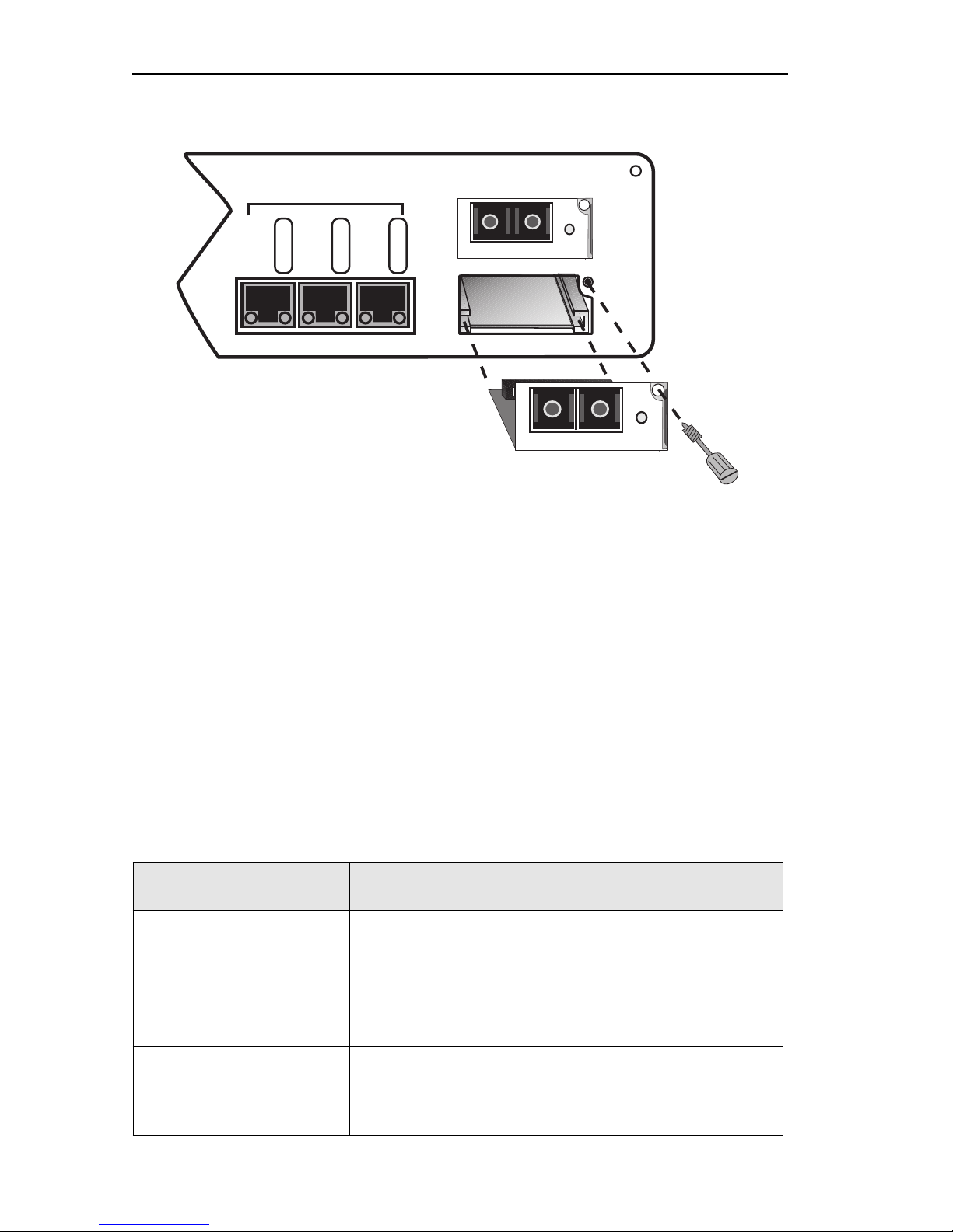
Unpacking and Installing Your SmartSTACK Ethernet ELS10-27
10BASE-T/100BASE-TX
LINK
25X 26X 27X
STATUS
LINK
STATUS
LINK
STATUS
EPIM100
LNK
EPIM-100FX
EPIM100
LNK
EPIM-100FX
Figure 2-2. Installing an EPIM
Note: Installing an EPIM replaces one of the 100TX ports.
2.3 INSTALLING THE SMARTSTACK ETHERNET
ELS10-27
Rack-mounting a SmartSTACK Ethernet ELS10-27
Table 2-3 describes some general considerations you should be aware of
before mounting a SmartSTACK Ethernet ELS10-27 in a rack assembly.
Table 2-3. General Considerations for Mounting a
SmartSTACK Ethernet ELS10-27
Consideration Discussion
Temperature Since the temperature within a rack assembly
may be higher than the ambient room
temperature, make sure the rack environment
temperature is within the Operating
Temperature range speciÞed in Appendix A.
Air Flow Make sure there is at least 2 inches (or more)
on both sides of the SmartSTACK Ethernet
ELS10-27 to allow for adequate air ßow.
2-6
Page 67
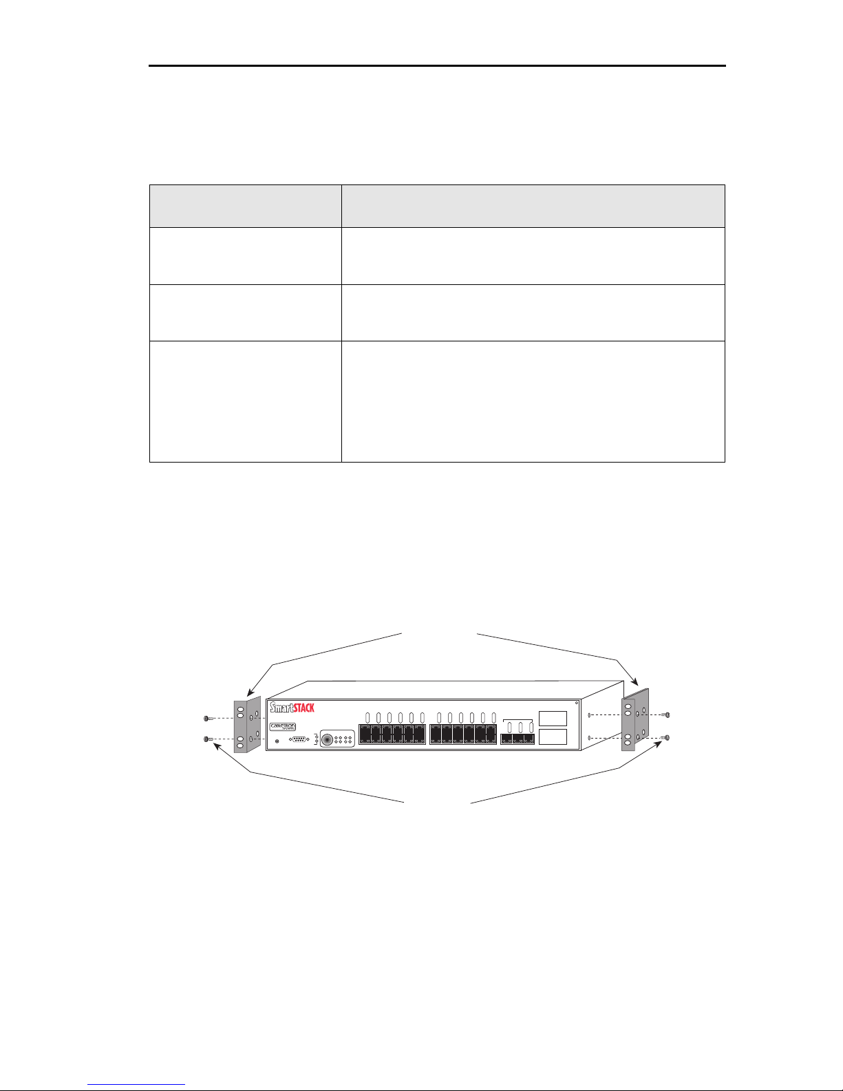
Unpacking and Installing Your SmartSTACK Ethernet ELS10-27
Table 2-3. General Considerations for Mounting a
SmartSTACK Ethernet ELS10-27 (Continued)
Consideration Discussion
Mechanical Loading Do not place equipment on top of a rack-
mounted SmartSTACK Ethernet ELS10-27.
Circuit Overloading Make sure the power supply circuit to the
rack assembly is not overloaded.
Grounding
(Earthing)
Rack-mounted equipment should be
grounded. In addition to the direct
connections to the main power supplies, make
sure all the other supply connections are also
grounded.
The SmartSTACK Ethernet ELS10-27 can be rack-mounted in a standard
19-inch equipment cabinet. To mount the SmartSTACK Ethernet
ELS10-27 in a rack assembly, apply the following steps:
1. Attach the rackmount brackets to both sides of the SmartSTACK
Ethernet ELS10-27 chassis, as shown in Figure 2-3.
Rackmount
Brackets (2)
ETHERNET SWITCH
ELS10-27TX
RESET
LINK
LINK
LINK
LINK
LINK
LINK
LINK
LINK
STATUS
STATUS
STATUS
STATUS
PORT STATUS MODE
STATUS
PWR
TX ACT FDX MON
CPU
COM
RX COL 100 USR
2X 4X 6X 8X 10X 12X 14X 16X 18X 20X 22X 24X
STATUS
LINK
STATUS
STATUS
STATUS
STATUS
10BASE-T/100BASE-TX
LINK
LINK
LINK
STATUS
STATUS
STATUS
LINK
25X 26X 27X
EPIM100
26
LINK
LINK
STATUS
STATUS
STATUS
27
Figure 2-3. Attaching Rackmount Brackets
2. Place the SmartSTACK Ethernet ELS10-27 chassis in the cabinet.
Screws (4)
2-7
Page 68
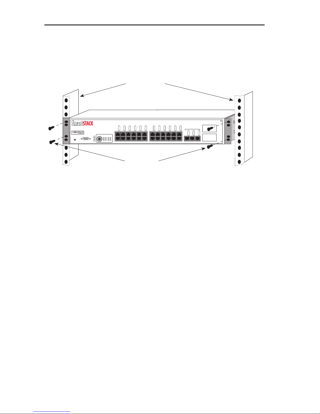
Unpacking and Installing Your SmartSTACK Ethernet ELS10-27
3. Secure the SmartSTACK Ethernet ELS10-27 with the rackmount
fasteners by inserting and securing a fastener through each of the
four slots in the rack-mount brackets, as shown in Figure 2-4.
19-Inch Rack
ETHERNET SWITCH
ELS10-27TX
RESET
LINK
LINK
LINK
LINK
LINK
LINK
LINK
LINK
LINK
STATUS
STATUS
STATUS
STATUS
STATUS
PORT STATUS MODE
STATUS
PWR
TX ACT FDX MON
CPU
COM
RX COL 100 USR
2X 4X 6X 8X 10X 12X 14X 16X 18X 20X 22X 24X
STATUS
LINK
STATUS
STATUS
STATUS
10BASE-T/100BASE-TX
LINK
LINK
STATUS
STATUS
STATUS
LINK
LINK
STATUS
25X 26X 27X
EPIM100
26
LINK
STATUS
STATUS
27
Screws (4)
Figure 2-4. Rack-mounting the SmartSTACK Ethernet ELS10-27
4. Once the SmartSTACK Ethernet ELS10-27 is installed, plug the AC
power cord into the AC power connector on the rear of the
SmartSTACK Ethernet ELS10-27 chassis. Plug the other end of the
power cord into a three-prong grounded outlet.
2.4 CHECKING THE POWER-UP DIAGNOSTICS
SEQUENCE
Before connecting any devices to the SmartSTACK Ethernet ELS10-27,
power on the unit and observe the power-up diagnostics sequence to
check for proper operation.
To observe the power-up diagnostics sequence completely, you may want
to repeat it. To restart the power-up sequence, press the reset button on
the front panel.
When you power up the SmartSTACK Ethernet ELS10-27, the following
occurs:
1. Power LED is ON.
2. CPU LED comes on.
3. Segment Status LEDs Sequence as Initialize Progresses.
2-8
Page 69

Unpacking and Installing Your SmartSTACK Ethernet ELS10-27
4. All Segment Status LEDs remain on.
5. All remaining LEDs turn on for several seconds.
6. All LEDs turn OFF, leaving the PWR and CPU LEDs ON.
7. In addition, the Port Link LEDs will turn on for those ports with
good links and the Segment Status LEDs will turn on (or ßash) when
the selected status condition is present.
Note: If a critical component fails diagnostics, the CPU LED will turn off and
the SmartSTACK Ethernet ELS10-27 will attempt to reboot. If the CPU
LED does not stay on, contact Cabletron Systems. Refer to Section 1.2.
2.5 CONNECTING THE LOCAL CONSOLE MANAGER
The Local Console Manager (LCM) is a command-line interface for
conÞguring, monitoring, and managing the SmartSTACK Ethernet
ELS10-27 via a VT 100 style terminal.
To connect the LCM:
1. Connect your ASCII terminal or terminal emulator to the out-ofband management RS232C port on the front panel of the
SmartSTACK Ethernet ELS10-27 using the standard console cable
shipped with the unit. (Only three wires are necessary: Receive Data,
Transmit Data and Ground.)
2. Set the terminal to 9600 baud, 8N1: 8 data bits, 1 stop bit, and no
parity, XON/XOFF ßow control.
3. Press the Enter key several times. If the SmartSTACK Ethernet
ELS10-27 and terminal are operational, LCM responds with the
ELS10-27 > prompt.
4. LCM is now ready to use.
Refer to Section 1.6, Local Console Manager, for a general overview of
LCM and the command syntax. LCM commands for conÞguring,
monitoring, and managing the SmartSTACK Ethernet ELS10-27 are
provided in the chapters dealing with those topics.
2-9
Page 70

Unpacking and Installing Your SmartSTACK Ethernet ELS10-27
2.6 CONNECTING TO THE NETWORK
This section provides the procedures for connecting UTP and multimode
Þber optic segments from the network or other devices to the
SmartSTACK Ethernet ELS10-27.
Ports 1 through 24 have RJ45 connectors for UTP connections. Ports 25-27
support FE-100TX UTP connections, with ports 26 and 27 being
transferable to optional EPIM100-FX Fast Ethernet Interface Modules.
Refer to Section 2.6.1 to make UTP connections.
Refer to Section 2.6.2 to make a Þber optic connection to an
EPIM100-FX.
2.6.1 Connecting UTP Cables
Before connecting a segment to the SmartSTACK Ethernet ELS10-27,
check each end of the segment to verify wire crossover.
Caution: To establish a link, you must have an odd number of crossovers
(preferably one) between 10BASE-T devices of the same type (i.e.,
from repeater to repeater or transceiver to transceiver).
Connect a twisted pair segment to the SmartSTACK Ethernet ELS10-27 as
follows:
1. Ensure that the device at the other end of the segment is connected
to the segment and is powered ON.
2. Refer to Figure 2-5. Connect the twisted pair segment to the
SmartSTACK Ethernet ELS10-27 by inserting the RJ45 connector on
the twisted pair segment into the desired RJ45 port.
2-10
Page 71
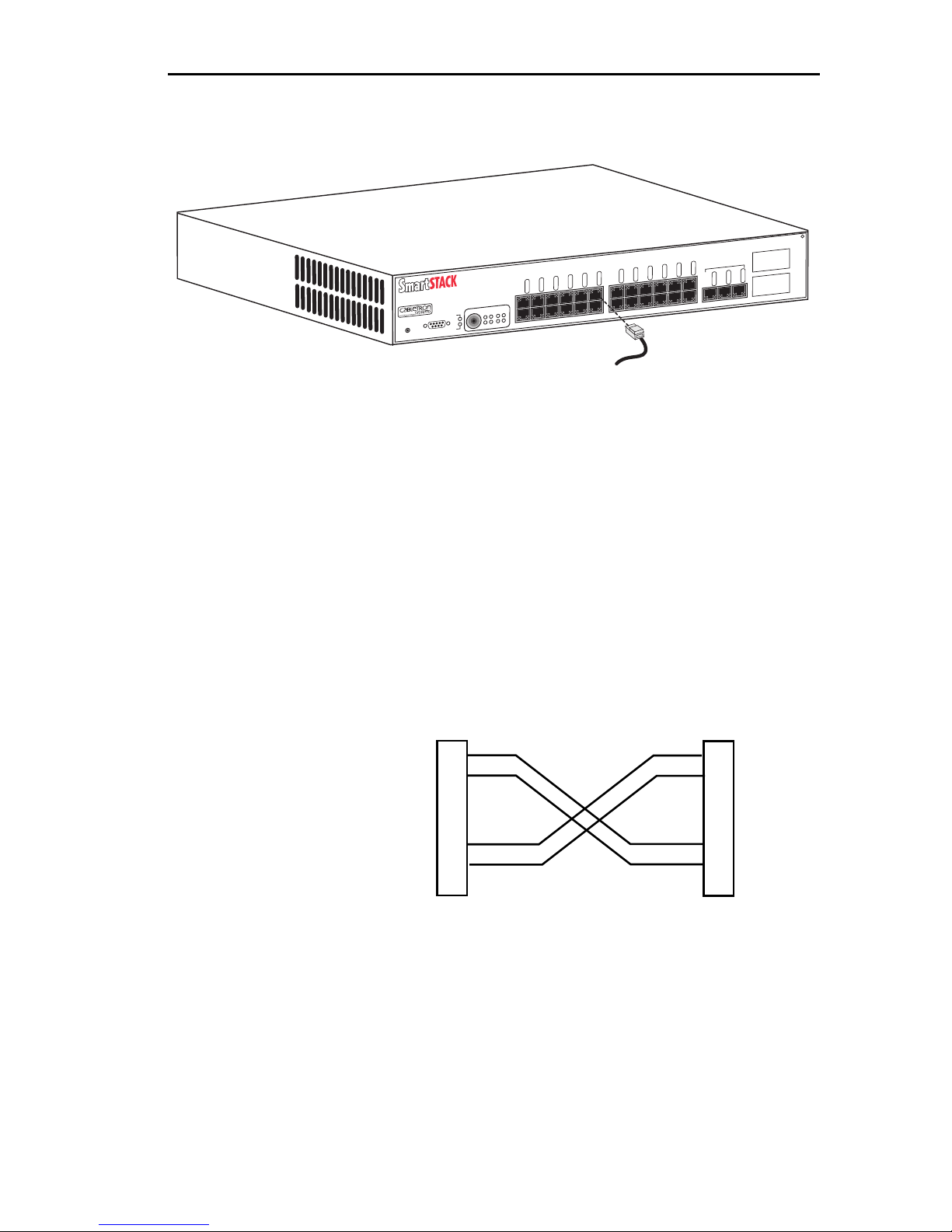
Unpacking and Installing Your SmartSTACK Ethernet ELS10-27
.
10BASE-T/100BASE-TX
STATUS
LINK
STATUS
LINK
STATUS
LINK
STATUS
LINK
STATUS
ETHERNET SWITCH
ELS10-27TX
RESET
PORT STATUS MODE
STATUS
PWR
CPU
COM
LINK
TX ACT FDX MON
2X 4X 6X 8X 10X 12X 14X 16X 18X 20X 22X 24X
RX COL 100 USR
LINK
STATUS
LINK
STATUS
LINK
STATUS
LINK
STATUS
LINK
STATUS
LINK
STATUS
LINK
STATUS
LINK
STATUS
LINK
25X 26X 27X
STATUS
LINK
STATUS
Figure 2-5. SmartSTACK Ethernet ELS10-27 Twisted Pair Connection
3. Verify that a Link exists by checking that the port LINK LED is on
(solid green). If the LINK LED is off, perform the following steps
until it is on:
EPIM100
26
27
a. Check that the 10BASE-T device at the other end of the twisted
pair segment is ON and connected to the segment.
a. Verify that the RJ45 connectors on the twisted pair segment have
the proper pinouts (Figure 2-6) and check the cable for continuity.
Note: RX+/RX- and
TX+/TX- must share a
common color pair.
Figure 2-6. Cable Pinouts - (RJ45) Crossover Cable
TO
ELS10-27 RJ-45 Port
TX+
TX-
RX+
RX-
1
2
3
6
10Base-T Device Port
TO
TX+
1
TX-
2
RX+
3
RX-
6
b. Check that the twisted pair connection meets the dB loss and
cable specifications.
If a link is not established, contact Cabletron Systems. Refer to Section
1.2, Getting Help, for details.
4. Repeat step 2, above, until all connections have been made.
2-11
Page 72

Unpacking and Installing Your SmartSTACK Ethernet ELS10-27
2.6.2 Connecting a Multimode Segment to the
EPIM100-FX
The EPIM100-FX has an SC style network port (see Figure 2-8). Cabletron
Systems supplies Þber optic cable that uses SC style connectors that are
keyed to ensure proper crossing over of the transmit and receive Þbers.
Caution: An odd number of crossovers (preferably one) must be maintained
between devices so that the transmit port of one device is connected to
the receive port of the other device and vice versa.
If the Þber optic cable being used has SC style connectors that do not
resemble MIC style connectors, or has SC connectors on one end and
a different type on the other, such as ST connectors, ensure that the
proper crossing over occurs.
Fiber Optic Network Connection
1. Remove the protective plastic covers from the Þber optic ports on the
applicable port on the module and from the ends of the connectors.
Caution: Do not touch the ends of the fiber optic strands, and do not let the ends
come in contact with dust, dirt, or other contaminants.
Contamination of the ends causes problems in data transmissions. If
the ends become contaminated, clean them with alcohol using a soft,
clean, lint-free cloth.
2. Insert one end of the SC connector into the EPIM100-FX installed in
the SmartSTACK Ethernet ELS10-27. See Figure 2-7.
3. At the other end of the Þber optic cable, attach the SC connector to
the other device.
2-12
Page 73
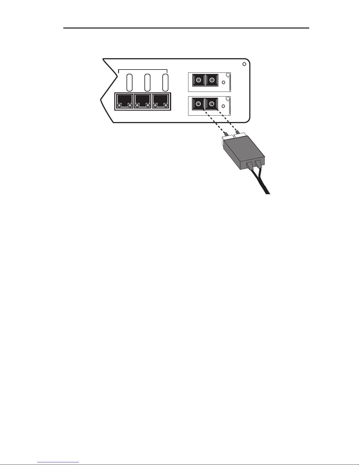
Unpacking and Installing Your SmartSTACK Ethernet ELS10-27
10BASE-T/100BASE-TX
LINK
LINK
STATUS
25X 26X 27X
STATUS
LINK
STATUS
EPIM100
LNK
EPIM-100FX
LNK
EPIM-100FX
EPIM100
Figure 2-7. EPIM100-FX Port
4. Verify that a Link exists by checking that the port LINK LED is solid
green. If the LINK LED is off, perform the following steps until it is
on:
a. Check that the power is turned on for the device at the other end
of the Link.
b. Verify proper crossing over of fiber strands between the
applicable port on the SmartSTACK Ethernet ELS10-27 and the
fiber optic device at the other end of the fiber optic link segment.
c. Verify that the fiber connection meets the dB loss specifications.
If a Link has not been established, contact Cabletron Systems. Refer to
Section 1.2, Getting Help, for details.
The SmartSTACK Ethernet ELS10-27 is now ready to be set up through
Local Management. Refer to Chapter 4, Monitoring and Managing Your
SmartSTACK Ethernet ELS10-27, to conÞgure the SmartSTACK Ethernet
ELS10-27.
2-13
Page 74

Unpacking and Installing Your SmartSTACK Ethernet ELS10-27
2-14
Page 75

CHAPTER 3
CONFIGURING Y OUR
SMARTSTACK ETHERNET ELS10-27
The SmartSTACK Ethernet ELS10-27 does not require any additional
conÞguration to operate as a standard, transparent switch. However, if
you want to use any of the SmartSTACK Ethernet ELS10-27Õs advanced
functions, you must Þrst assign an IP (Internet Protocol) address on the
SmartSTACK Ethernet ELS10-27 to communicate with a Simple Network
Management Protocol (SNMP) manager.
To initially assign an IP address, you can use the Local Console Manager
(LCM). LCM is a command-line interface built into the SmartSTACK
Ethernet ELS10-27 that allows you to conÞgure and manage the
SmartSTACK Ethernet ELS10-27 through the out-of-band RS232C
connection attached to any non-intelligent terminal, or a PC emulating a
non-intelligent terminal. (See Section 3.1, Assigning IP Addresses.)
Once you have assigned an IP address, you can use SNMP-compliant
network management tools to conÞgure and manage the SmartSTACK
Ethernet ELS10-27.
ConÞguration parameters are stored in an SNMP standard Management
Information Base (MIB). All SmartSTACK Ethernet ELS10-27 MIB
variables are listed and described in the SmartSTACK Ethernet ELS10-27
MIB Reference Guide.
Note: There are some configuration options that cannot be configured using
LCM commands. You may need to modify your configuration using an
NMS. See Section 3.14, Modifying MIB Variables.
The following sections describe how to conÞgure the optional parameters
of the SmartSTACK Ethernet ELS10-27 using LCM commands, including:
¥ Assigning IP addresses
¥ Enabling and disabling bridging
¥ Displaying bridging functions
¥ Enabling and disabling trunking
¥ Displaying trunking status
¥ DeÞning and deleting virtual workgroups
3-1
Page 76

Configuring Your SmartSTACK Ethernet ELS10-27
¥ Assigning a community name
Note: You can use the LCM erase command to erase all configuration
information and return the unit to default settings on the next system
reset.
If you are using a network management tool other than LCM, refer to its
accompanying documentation.
3.1 ASSIGNING IP ADDRESSES
You can assign an IP that can be used for the the entire device. IP
addresses are divided into classes based on what portion of the address is
network or port information. The address classes are A, B, and C.
¥ Class A addresses are used in very large networks that support many
ports. The Þrst byte identiÞes the network and the other three bytes
identify the node. The Þrst byte of a class A address must be in the
range 1-126. The address 100.125.110.10 would identify node
125.110.10 on network 100.
¥ Class B addresses are used for medium sized networks. The Þrst two
bytes identify the network and the last two identify the node. The Þrst
byte of a class B address must be in the range 128-191. The address
128.150.50.10 identiÞes node 50.10 on network 128.150.
Class C addresses are used for small networks. The Þrst three bytes
identify the network and the last byte identiÞes the port. The Þrst byte of
a class C address must be in the range 192-223. The address 192.138.217.10
identiÞes node 10 on network 192.138.217.
3.1.1 IP Address Configuration
SmartSTACK Ethernet ELS10-27 offers two basic methods to conÞgure
the IP address for the device. These two methods are BOOTP and the user
interfaces. An IP address can also be learned by receiving an SNMP
packet from the network. This IP address will be used solely to
communicate with the network manager host.
3-2
Page 77

Configuring Your SmartSTACK Ethernet ELS10-27
User Interfaces (Telnet)
If the IP address is modiÞed via Telnet you are prompted to ensure this
change is desired. If this mechanism is used to make the change, the
change will not take affect until the next reboot.
In 802.1d mode the SmartSTACK Ethernet ELS10-27 allows for a single IP
address set for the entire device. The single IP is accessible from any front
panel port.
You are also able to conÞgure a default gateway. The default gateway is
used to send IP packets to an end system that does not have an entry in
the SmartSTACK Ethernet ELS10-27Õs ARP cache. The default gateway is
usually a router and the parameter set for default gateway is the IP
address of the router interface to which the SmartSTACK Ethernet
ELS10-27 is connected.
In 802.1Q mode, an IP address per vlan is allowed. You must specify a
VLAN ID to use to access that IP subnet. Only one VLAN ID per IP
subnet is allowed.
To assign an IP address, at the LCM prompt:
Type
ipaddr <IP ADDRESS>
For example, ipaddr 192.138.217.40 will set the IP address
192.138.217.40. LCM responds by displaying the IP address table, as
shown under the ipaddr command.
BOOTP
If there is not an in-band IP address assigned to the device in non-volatile
memory, the runtime image attempts to determine an in-band IP address
from the network. The runtime image will send out a BOOTP request to
determine its IP address. The requests will be sent out periodically until a
response is received. An interval of which BOOTP requests will be issued
is per the BOOTP speciÞcation. This retry mechanism goes on for
approximately two minutes. If after two minutes a response is not
received, the system waits for approximately Þve minutes before starting
the process over again. The Þrst response the device receives is stored in
non-volatile memory as the in-band IP address. As soon as an IP address
is received via BOOTP, the module will cease sending out BOOTP
requests completely. If the device has an IP address in non-volatile
memory the module will not send out BootP requests.
3-3
Page 78

Configuring Your SmartSTACK Ethernet ELS10-27
BOOTP is not supported in 802.1Q mode. If the system is running in
802.1Q mode, and a reboot of the unit takes place, the unit begins
operating from Flash Boot sectors. While in Flash Boot sectors, the
BOOTP function will not tag packets. When the unit becomes fully
operational, it resumes operation in 802.1Q mode and tags packets.
3.1.2 Displaying IP Addresses
To display IP addresses, subnet masks, and MAC addresses of all ports on
the SmartSTACK Ethernet ELS10-27 you are conÞguring, at the LCM
prompt:
Type address display
The address display command will display the MAC addresses, whether
the address has been learned, the port the address is known on, and the
age of the address entry.
Address Type Port Age(secs) VLAN ID VLAN Name
00:40:27:00:55:bf Learned 26 1 0x003 Blue
00:40:27:00:58:17 Learned 26 14 0x003 Blue
00:00:0c:19:ce:35 Learned 26 4 0x003 Blue
00:80:cf:00:02:b7 Learned 26 215 0x003 Blue
00:00:c0:d8:f2:9a Learned 26 80 0x002 Green
00:40:27:07:b4:9d Learned 26 134 0x003 Blue
00:00:c0:b7:08:0e Learned 26 10 0x003 Blue
08:00:20:79:fb:df Learned 17 1 0x005 Green
00:00:1d:1d:63:3c Learned 26 0 0x003 Blue
00:00:86:09:99:31 Learned 26 8 0x003 Blue
08:00:20:0f:ca:03 Learned 26 53 0x005 Green
Address Type Port Age(secs) VLAN ID VLAN Name
08:00:20:7b:d5:58 Learned 26 223 0x003 Blue
08:00:20:72:0b:1d Learned 26 55 0x003 Blue
08:00:09:56:01:fe Learned 26 18 0x003 Blue
3-4
Page 79

Configuring Your SmartSTACK Ethernet ELS10-27
00:00:c0:aa:08:0e Learned 16 10 0x002 Green
00:04:ac:26:bd:8b Learned 26 170 0x003 Blue
08:00:69:07:19:a8 Learned 26 24 0x003 Blue
00:a0:c9:37:eb:17 Learned 26 130 0x005 Green
00:00:1d:1a:80:d7 Learned 26 0 0x003 Blue
00:00:c0:1a:7a:0e Learned 26 143 0x003 Blue
Enter <CR> to continue, Cntl-C to exit:
3.1.3 Deleting an IP Address
To delete an IP address, at the LCM prompt:
Type ipaddr 0.0.0.0
LCM responds by redisplaying the current IP address table.
3.1.4 Changing a Subnet Mask
You can optionally set the subnet mask. A subnet mask is a 32-bit address
mask used in IP to specify a particular subnet. If the subnet mask is
0.0.0.0, the SmartSTACK Ethernet ELS10-27 will automatically convert
the displayed mask to the standard default, based on the IP address class.
(Class A address masks are 255.0.0.0, Class B address masks are
255.255.0.0, Class C address masks are 255.255.255.0.)
To change the subnet mask, at the LCM prompt:
Type
ipaddr <IP ADDRESS> <SUBNET MASK>
For example, ipaddr 192.138.217.40 255.255.240.0 would set the
subnet mask to 255.255.240.0. LCM responds by redisplaying the
current address table.
3.1.5 Setting the Default Gateway
The Default Gateway is set using the Route command. Refer to the Route
command on page 1-35.
3-5
Page 80

Configuring Your SmartSTACK Ethernet ELS10-27
3.2 OPERATIONAL IMAGE
SmartSTACK Ethernet ELS10-27 supports the in-band TFTP loading of
Þrmware images. The method for downloading Þrmware into ßash is an
Òon-lineÓ download method. Functionality of the download process is
supported by the ctdownload mib.
On-line download means that the operation of the device is not affected
by the downloading process. The operational image operates out of RAM
and the downloading process erases ßash and loads the new image
directly into ßash. If the download is unsuccessful and ßash is not
programmed properly, the device will use a BOOTP upon the next boot
cycle to attain an image.
In the situation where the device boots up and Þnds an empty or corrupt
ßash, the device will use BOOTP to discover an image for downloading.
The device allows you to set a BOOTP Gateway address. This allows the
device to pass BOOTP requests through a router that does not support
proxy ARP. This process allows you to execute runtime downloads and
be certain that if a failure during download occurs, the device is able to
send BOOTP requests through the router.
BOOTP (RFC 951) and the Client side of TFTP are implemented to
support automatic and SNMP controlled downloading.
The BOOTP protocol is a simple request/reply protocol that allows a
network station to dynamically learn boot information from a Boot
parameter server. SmartSTACK Ethernet ELS10-27 uses BOOTP to
discover any unknown items on the following list.
¥ Our IP Address
¥ DownLoad Filename
¥ DownLoad Server IP Address
¥ Gateway IP Address to DownLoad Server (if needed)
Once any unknown boot information is acquired via BOOTP, the TFTP
Protocol is used to request DownLoad Filename from DownLoad Server and
store it in the Flash Þle system.
3-6
Page 81

Configuring Your SmartSTACK Ethernet ELS10-27
IDENT Command
The IDENT command is enhanced to support displaying the following
variables:
Part Number:
Power-up test code:
Diagnostic data:
Last Image File Name
Last Server IP Address
Flash Size
Boot Revision
Tephra Revision
Operational Status
Error String
3.3 IGMP
The Internet Group Management Protocol allows the establishment of IP
multicast groups. IGMP is supported by snooping on IGMP messages to
add entries to the forwarding table to limit the forwarding of multicast
packets only to ports where IP Multicast devices have been heard from.
The SmartSTACK Ethernet ELS10-27 acts as an IP Multicast Þlter and will
not forward IP Multicast packets onto segments that do not have any
group members. It does this by listening for IGMP packets and creating
and/or modifying the appropriate Þlters. It makes use of a combination
of polling and a time-out functions on groups and segments to decide
when to delete all members of the group.
SmartSTACK Ethernet ELS10-27 does not act as an IGMP router, meaning
it WILL NOT:
¥ decrement the TTL value
¥ speciÞcally Þlter out packets with TTLÕs of 1
¥ Þlter packets with IP Multicast source addresses
¥ participate in IGMP Routing Protocols
¥ keep statistics on IP Multicast packets Þltered or forwarded
In order to ensure awareness of all ports where routers reside that are
interested in IP Multicast packets, we will also monitor IP Multicast
3-7
Page 82

Configuring Your SmartSTACK Ethernet ELS10-27
routing protocols to determine their location and adjust the Þlters
accordingly.
When subsequent queries are heard by the CPU, the CPU notes if any
response is heard for each group. A count is kept for each group
indicating the number of times a query was heard and there was no
response received. When the count reaches its maximum value of 5 the
group entry is modiÞed and packets for that group are only forwarded to
the CPU and to the query port. If an IGMPv2 speciÞc query is heard, this
is not counted as having received a general query. It only counts as a valid
query for that group.
If an IP Multicast/UDP packet is received by the CPU that has not had a
response issued for it, an entry is placed in the data base restricting
forwarding of those packets to just the CPU. The idea is, rather than place
entries in the data base for all unwanted entries, wait until trafÞc is heard
from the unwanted entries and then restrict it. The number of entries
should therefore be smaller, and based on how quickly the CPU can
respond, a limited amount of unwanted trafÞc will leak through initially.
This is known as Dynamic IP Multicast Þltering and the use of it is user
selectable. The default value for this selection is off. If, after creating this
dynamic Þlter, there is a response, the response port is added to the Þlter.
Once the response has been heard, if a querier is known, or is later heard
from, it too is added to the entry. This is done with both the presence and
absence of a querier.
If this feature is not selected (the default), a hardware Þlter is set to Þlter
out all IP Multicast packets that are UDP packets from being received by
the CPU.
You are also able to select whether you want the unit to act as an IGMP
querier. This feature is used in the absence of any other IGMP queriers on
the network.
Five commands are used to control the following functions:
¥ Enable/Disable IGMP Þltering - the default is enabled.
¥ Add/Delete a static IP Multicast Þlter on a group of ports.
¥ Enable/Disable Dynamic IP Multicast Þltering - the default is
disabled.
¥ Enable/Disable the unit to act as a querier - the default is disabled.
¥ Specify ports to be included in all Þlters (expected querier ports).
3-8
Page 83

Configuring Your SmartSTACK Ethernet ELS10-27
3.4 ENABLING BRIDGING
The LCM bridge command allows you to set bridging options for a single
port or a range of ports. The options include:
¥ off
¥ on (the default with BPDU enabled)
¥noBPDU
BPDU (Bridge Protocol Data Unit) is a data unit transmitted as part of the
IEEE 802.1d Spanning Tree protocol. The exchange of BPDUs allows
bridges within a network to logically conÞgure the network as a single
spanning tree.
Note: Selecting the noBPDU option could make your network inoperable
because the SmartSTACK Ethernet ELS10-27 would be unable to detect
loops.
Using LCM to enable bridging for a port or port range, at the LCM
prompt:
1. Type bridge [PORT-RANGE [{off|on|noBPDU}]]
For example, bridge 2 on would enable bridging on port 2.
LCM responds:
Port 2 bridging: Transparent Bridging
3.5 DISABLING BRIDGING
To turn off the bridging function for a port or port range, at the LCM
prompt:
1. Type bridge [PORT-RANGE] off
For example, bridge 2 off would disable bridging on port 2.
LCM responds:
Port 2 bridging: off
3-9
Page 84

Configuring Your SmartSTACK Ethernet ELS10-27
3.6 DISPLAYING BRIDGING FUNCTIONS
To display the bridging functions that are enabled for all ports, at the
LCM prompt:
1. Type bridge
LCM responds with a list of all ports and the bridging function that is
enabled. For example, typing bridge would display the bridging
status for all ports.
Usage: bridge [PORT-RANGE [{off|on|noBPDU{]]
Port 1 bridging: Transparent Bridging
Port 2 bridging: Transparent Bridging
Port 3 bridging: Transparent Bridging
Port 4 bridging: Transparent Bridging
.
.
.
Port 27 bridging: off
You could also type bridge [PORT-RANGE] to look at a speciÞc range
of ports. For example bridge 2-4 would display bridging functions
for ports 2, 3, and 4.
3.7 ENABLING TRUNKING
If your network conÞguration requires you to connect two or more
SmartSTACK Ethernet ELS10-27s (or other devices capable of trunking)
together, but the applications you are running over the network require
more than 100 Mbps of bandwidth per connection, you can use the builtin trunking feature to increase bandwidth up to 600 Mbps, without
installing additional hardware on your network.
Trunking is a Cabletron Systems proprietary extension to the 802.1D
Spanning Tree algorithm. It enables you to use multiple segments to
connect SmartSTACK Ethernet ELS10-27s together, while maintaining
Þrst-in, Þrst-out ordering of Ethernet packets. In addition, if any of the
Ethernet segments conÞgured for trunking become inoperable, those
Ethernet segments are automatically bypassed.
3-10
Page 85
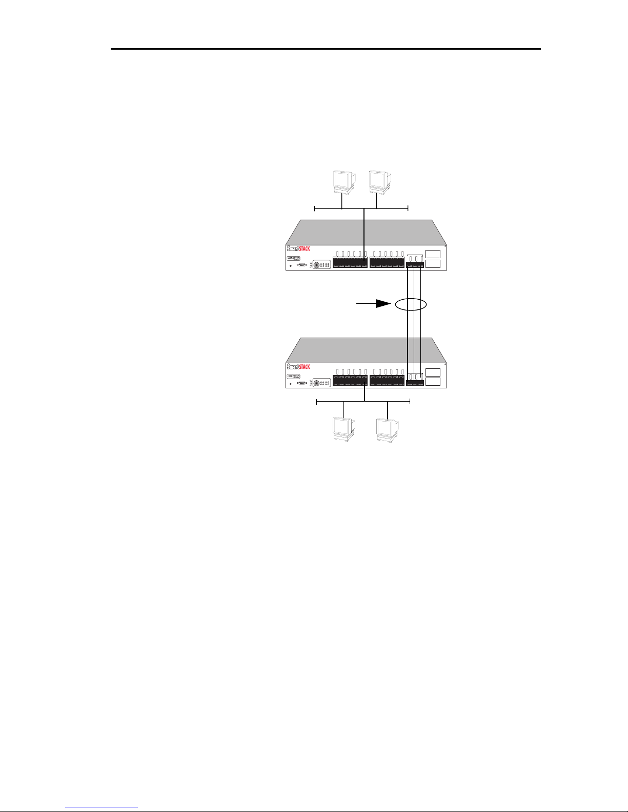
Configuring Your SmartSTACK Ethernet ELS10-27
Figure 3-1 shows two SmartSTACK Ethernet ELS10-27s connected by
three 100BASE-TX crossover cables. You can connect up to three ports for
sharing the traffic load. The connections must be point-to-point. That is,
there cannot be any other devices on the Ethernet segments.
ELS10-27
ETHERNET SWITCH
ELS10-27TX
RESET
COM
LINK
PORT STATUS MODE
STATUS
PWR
TX ACT FDX MON
CPU
RX COL 100 USR
2X 4X 6X 8X 10X 12X 14X 16X 18X 20X 22X 24X
LINK
LINK
LINK
LINK
LINK
STATUS
STATUS
STATUS
STATUS
STATUS
STATUS
100BASE-TX Crossover Cables
(providing 600 Mbps of bandwidth)
ETHERNET SWITCH
ELS10-27TX
RESET
COM
LINK
PORT STATUS MODE
STATUS
PWR
TX ACT FDX MON
CPU
RX COL 100 USR
2X 4X 6X 8X 10X 12X 14X 16X 18X 20X 22X 24X
LINK
LINK
LINK
LINK
LINK
STATUS
STATUS
STATUS
STATUS
STATUS
STATUS
LINK
LINK
LINK
LINK
LINK
LINK
STATUS
STATUS
STATUS
STATUS
STATUS
LINK
LINK
LINK
LINK
LINK
LINK
STATUS
STATUS
STATUS
STATUS
STATUS
STATUS
STATUS
10BASE-T/100BASE-TX
LINK
STATUS
25X 26X 27X
10BASE-T/100BASE-TX
LINK
STATUS
25X 26X 27X
LINK
LINK
EPIM100
26
LINK
STATUS
STATUS
27
ELS10-27
EPIM100
26
LINK
STATUS
STATUS
27
Figure 3-1. Trunk Connections
Trunk Groups
Each set of connections between two SmartSTACK Ethernet ELS10-27s is
called a Trunk Group. You can create one Trunk Group, having up to three
ports, to interconnect your SmartSTACK Ethernet ELS10-27s.
Each SmartSTACK Ethernet ELS10-27 determines which ports are part of
which Trunk Group. After Trunk Group conÞguration, the SmartSTACK
Ethernet ELS10-27s complete the standard 802.1D Spanning Tree state
changes, treating each Trunk Group as a single 802.1D Spanning Tree
port.
802.1D Spanning Tree takes about thirty seconds to resolve which
SmartSTACK Ethernet ELS10-27 ports are to become forwarding ports.
As ports within a Trunk Group become forwarding ports, trafÞc within
the Trunk Group is momentarily halted to guarantee the Þrst-in, Þrst-out
ordering of the Ethernet packets.
3-11
Page 86

Configuring Your SmartSTACK Ethernet ELS10-27
Note: The SmartSTACK Ethernet ELS10-27-to-SmartSTACK Ethernet
ELS10-27 connections must be point-to-point. There cannot be any other
devices on those Ethernets. The ports used for trunking can be in any
order. However, both ends of the SmartSTACK Ethernet ELS10-27-toSmartSTACK Ethernet ELS10-27 connections must have trunking
turned on for the ports that are being used for the connections.
3.8 DISABLING TRUNKING
To turn off trunking, at the LCM prompt:
Type trunk <PORT-RANGE> off
For example, trunk 25-27 off
3.9 DISPLAYING TRUNKING STATUS
To check the status of your current trunking conÞguration, at the LCM
prompt:
1. Type trunk <PORT-RANGE>
The display could look like the following:
Note: IP Addresses are not required for trunking to function.
ELS10-27 > trunk 25-27
Port 25 trunking joined to Bridge MAC Addr 00:40:27:00:06:1f IP Addr 0.0.0.0
Port 26 trunking joined to Bridge MAC Addr 00:40:27:00:06:c3 IP Addr 0.0.0.0
Port 27 trunking joined to Bridge MAC Addr 00:50:36:00:07:4a IP Addr 0.0.0.0
To check the status for ports conÞgured for trunking, at the LCM prompt:
1. Type status <PORT-RANGE>
3-12
Page 87

Configuring Your SmartSTACK Ethernet ELS10-27
The display could look like the following:
ELS10-27 > status 1
Port 1 Status
Type/Speed: 10B-TPX/10Mbits
Port Mirroring: No
Duplex Mode: Half Duplex
Bridging: Transparent Bridging
Enabled/Disabled: Enabled, Rip listening
Spanning Tree: Forwarding
Trunking State: Off
Pkts Transmitted: 1693
Pkts Received: 0
Carrier Losses: 1693
Total Collisions: 0
Excess Collisions: 0
RX Missed pkts: 0
RX Runt pkts: 0
RX FCS/Align Errs: 0
Internal TX Errs: 0
Type <CR> to display port 2 status...>
The following conditions can be displayed:
¥ Broken Ñ Trunking is enabled, but the port in non-operational.
¥ Closed (or Oneway) Ñ Trunking is enabled, and the Trunking Protocol
is attempting to establish a trunk connection.
¥ Heldown Ñ Trunking is enabled, but the trunk connection was
rejected. After a short time-out period, another attempt is
automatically initiated to establish a good trunk connection.
¥ Joined Ñ Trunking is enabled, and the Trunking Protocol has
established a good trunk connection.
¥ Off Ñ Trunking is not enabled.
¥ Perturbed Ñ Trunking is enabled, and a good trunk connection has
been established. However, the forwarding of data packets is
temporarily suspended to allow for a change in the membership of the
Trunk Group.
3-13
Page 88

Configuring Your SmartSTACK Ethernet ELS10-27
3.10 PORT MIRRORING
The mirror command has two forms. One will allow the user to mirror all
inbound and outbound trafÞc from one port to another. The second will
allow all packets with speciÞc destination MAC addresses to be mirrored
to a particular port. Up to four destination MAC addresses may be
mirrored simultaneously.
mirror [port {add | del[ete]} SRC-PORT DEST-PORT]
[add[ress]{add | del[ete]} MAC-ADDRESS DEST-PORT]
[on | off]
By entering the command alone the present mirror selections will be
displayed.
ELS10-27>mirror
port 5 is being mirrored to port 25.
ELS10-27>mirror
The mirror port is 7
02:98:10:03:10:09
98:45:82:94:54:76
3.11 DEFINING AND DELETING WORKGROUPS
The SmartSTACK Ethernet ELS10-27 allows you to deÞne logical groups
of associated ports (virtual workgroups) to provide a more efÞcient ßow
of trafÞc across your Ethernet network.
Virtual workgroups offer you the ability to limit broadcasts and unicasts
to logical domains within the network. Workgroup destinations are
recognized by the SmartSTACK Ethernet ELS10-27 and packets are
routed directly to ports within the workgroup, eliminating the need to
perform a general broadcast across each segment of the network to Þnd
speciÞc host addresses.
Figure 3-2 shows an SmartSTACK Ethernet ELS10-27 that has been
programmed to identify workgroups A and B. Workgroup A uses ports 3
through 5,13 and 16 and workgroup B uses ports 7, 11, 16 and 24. Port 16
connects a segment that contains both workgroup A and workgroup B
hosts.
3-14
Page 89
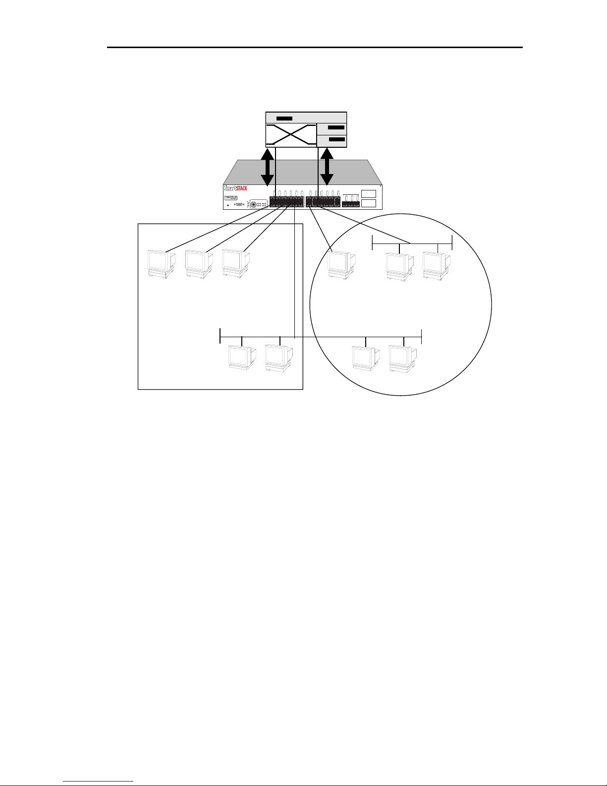
Configuring Your SmartSTACK Ethernet ELS10-27
Router
AB
ELS10-27
EPIM100
10BASE-T/100BASE-TX
STATUS
26
LINK
LINK
LINK
STATUS
STATUS
STATUS
27
25X 26X 27X
Workgroup B
B
B
B
B
A
A
Workgroup A
ETHERNET SWITCH
ELS10-27TX
RESET
A
LINK
LINK
LINK
LINK
LINK
LINK
LINK
LINK
LINK
LINK
LINK
STATUS
STATUS
STATUS
STATUS
STATUS
PORT STATUS MODE
STATUS
PWR
TX ACT FDX MON
CPU
COM
RX COL 100 USR
2X 4X 6X 8X 10X 12X 14X 16X 18X 20X 22X 24X
STATUS
LINK
STATUS
STATUS
STATUS
STATUS
STATUS
B
A
A
Figure 3-2. Defining Virtual Workgroups
The LCM commands used to create the previous conÞguration are as
follows:
1. To create workgroup A on ports 3, 4, 5, 13, and 16:
SmartSTACK Ethernet ELS10-27 > workgroup A 3-5,13,16
LCM responds with the following display:
Name: a
Ports: 3, 4, 5, 13, 16
2. To create workgroup B on ports 7, 11, 16, and 24:
SmartSTACK Ethernet ELS10-27 > workgroup B 7,11,16,24
LCM responds with the following display:
Name: b
Ports: 7, 11, 16, 24
3-15
Page 90

Configuring Your SmartSTACK Ethernet ELS10-27
Port 16 has been assigned to a segment that includes ports that belong to
workgroup A and workgroup B. Port 13 connects workgroup A to the
router and port 24 connects workgroup B to the router.
All packets remain within the workgroup.
Use the LCM command, workgroup, to create, modify, and delete virtual
workgroups. The full syntax of the command is as follows:
workgroup [NAME [{delete | PORT-RANGE}]]
To display all of the workgroups deÞned by the SmartSTACK Ethernet
ELS10-27, at the LCM prompt:
Type workgroup
To display information about a speciÞc workgroup, at the LCM prompt:
Type workgroup NAME
To create or modify a workgroup, at the LCM prompt:
Type workgroup NAME PORT-RANGE
To delete a workgroup, at the LCM prompt:
Type workgroup NAME delete
To create or modify the port list for a speciÞc workgroup, at the LCM
prompt:
Type workgroup NAME PORT-RANGE
To display the network classiÞcation of a speciÞc workgroup, at the LCM
prompt:
Type workgroup NAME
3.12 ASSIGNING A COMMUNITY NAME
A community name is similar to a password. You use the same steps to
assign a new community name or to change an existing community
name. You can then enter a community name to perform any SNMP sets.
The default password is public the Þrst time you access the device.
To assign a community name, at the LCM prompt:
1. Type community
2. Enter the old community name.
3-16
Page 91

Configuring Your SmartSTACK Ethernet ELS10-27
3. If one has not been assigned, public is the default name.
4. Enter the new community name.
5. LCM prompts you to verify the new community name by retyping
it.
6. Retype the new community name.
3.13 CONFIGURING BROADCAST/MULTICAST STORM
PROTECTION
The SmartSTACK Ethernet ELS10-27 provides automatic protection
against broadcast/multicast storms. Broadcast storms are excessive
broadcasts to all ports, typically caused by a malfunctioning device. They
can result in severe network performance problems, including causing
the network to crash.
To protect against broadcast/multicast storms, you must deÞne an
acceptable rate for multicast trafÞc across a port. In many ways, this
feature is similar to Þltering.
Each SmartSTACK Ethernet ELS10-27 port can be individually
conÞgured for automatic multicast storm protection. You deÞne what
level of multicasts the SmartSTACK Ethernet ELS10-27 will recognize as a
multicast storm by specifying the number of multicast packets that can be
received within a given time period.
For example, if you conÞgure SmartSTACK Ethernet ELS10-27 to receive
onto Port 3 no more than 50,000 multicasts per 10 seconds, any multicasts
destined for Port 3 are discarded after the Þrst 50,000 multicasts. After 10
seconds have elapsed, another 50,000 multicasts to Port 3 will be allowed.
This maintains an effective maximum rate of 50,000 multicast packets per
10 seconds.
3.14 MODIFYING MIB VARIABLES
SpeciÞc instructions for controlling SmartSTACK Ethernet ELS10-27
operations, modifying parameters, and so on, depend on the NMS you
are using. This manual provides instructions for using LCM commands.
However, LCM commands do not exist for all conÞguration options. You
may need to modify your conÞguration using an NMS.
3-17
Page 92

Configuring Your SmartSTACK Ethernet ELS10-27
This section provides several common MIB variables you may want to
change. Refer to the SmartSTACK Ethernet ELS10-27MIB Reference Guide
for a complete listing and description of MIB variables.
Each variable is Þrst described in words, and is then identiÞed in MIB
form, for example, els10-27adminGetPass - {els10-27admin 3}. The
Display String line shows the range of values that can be used for the
given parameter. In each case, the DisplayString is a string of ASCII
characters.
3.15 SYSTEM CONTACT
The system contact parameter identiÞes the contact person who is
responsible for operating the SmartSTACK Ethernet ELS10-27. Typically,
this parameter includes the personÕs name, company or division name,
and telephone number.
sysContact - {system 4}
DisplayString (SIZE (0..255))
3.16 SYSTEM NAME
The system name is a name assigned to the SmartSTACK Ethernet
ELS10-27 by the network administrator. By convention, the system name
is the fully qualiÞed domain name. (This name then becomes the LCM
prompt.)
sysName - {system 5}
DisplayString (SIZE (0..255))
3.16.1 System Location
The system location identiÞes the physical location of the SmartSTACK
Ethernet ELS10-27.
sysLocation - {system 6}
DisplayString (SIZE (0..255))
3-18
Page 93

Configuring Your SmartSTACK Ethernet ELS10-27
3.16.2 Community Names
The set community name variable (from the Cabletron proprietary MIB),
must be initialized with the correct community name passwords.
All requests from any SNMP manager contain a community name Þeld.
For set requests, the community name must match the set password;
otherwise, the request will be rejected by the SmartSTACK Ethernet
ELS10-27. For get requests, the community name must match either the
set or the get community name.
Set Community Name
The set community name variable (els10-27adminAnyPass) and get
community name variable (els10-27adminGetPass) must be set to the
value of the community name used by the SNMP manager for
performing either set or get operations. A zero length community name
means that any community name is acceptable.
els10-27adminAnyPass - {els10-27admin 2}
DisplayString (SIZE (0..24))
els10-27adminGetPass - {els10-27admin 2}
DisplayString (SIZE (0..24))
3.16.3 Aging Parameter
Dynamic (learned) addresses are automatically deleted from the
SmartSTACK Ethernet ELS10-27 Bridge Address Table after a certain
length of time. The aging time default is Þve minutes, as set by the IEEE
802.1d standard. However, you can change the aging parameter with the
MIB variable dot1dTpAgingTime.
The SmartSTACK Ethernet ELS10-27 continually compares the actual age
of each dynamic address against the age speciÞed by the
dot1dTpAgingTime parameter, and deletes any addresses that are older
than the age speciÞed (or older than Þve minutes if you are using the
default). Typically, there is no need to set the aging time to a very small
number because the SmartSTACK Ethernet ELS10-27 Bridge Address
Table supports 979 addresses.
3-19
Page 94

Configuring Your SmartSTACK Ethernet ELS10-27
3-20
Page 95

CHAPTER 4
MONITORING AND MANAGING
YOUR SMARTSTACK ETHERNET ELS10-27
Monitoring the SmartSTACK Ethernet ELS10-27 consists of collecting and
analyzing statistics and system status information.
You can use the Select button on the front panel of the SmartSTACK
Ethernet ELS10-27 to monitor segment status on any of the Ethernet ports.
Refer to Section 2.1 for a description of the segment status options.
Basic management of the SmartSTACK Ethernet ELS10-27 consists of
disabling or enabling Ethernet ports, setting the community name for the
SmartSTACK Ethernet ELS10-27, and changing the baud rate for your
Local Console Manager (LCM) connection.
4.1 SMARTST ACK ETHERNET ELS10-27 MANAGEMENT
TOOLS
LCM is a command-line interface built into the SmartSTACK Ethernet
ELS10-27 that enables you to monitor and manage the SmartSTACK
Ethernet ELS10-27 through the out-of-band RS232C connection attached
to any non-intelligent terminal. You can also use one of the following
Cabletron Systems Network Management Stations (NMSs), or a standard
SNMP-based NMS to manage the SmartSTACK Ethernet ELS10-27:
¥ SPECTRUM
¥ SPMA
¥ SPEL
¥ Any SNMP-based NMS
4-1
Page 96

Monitoring and Managing Your SmartSTACK Ethernet ELS10-27
4.2 MIB SUPPORT
This section lists the SNMP MIBs supported by SmartSTACK ELS10-27.
These MIBs allow the user to conÞgure virtually all features and
functions of the product. These MIBs also allow this device to be
managed by an SNMP management application.
RFC1213 MIBII
RFC1757 RMON (Statistics, History, Alarm, and
Event)
RFC1493 Bridge MIB
ctmib2ext
ctbridge ctBridgeStp only
ctdownload
ctfastethernet mib
stacktrunk-mib
FlowControl
4.3 RMON SUPPORT
SmartSTACK Ethernet ELS10-27 has the ability to support four of the nine
RMON MIB groups. The four groups are Ethernet Statistics, History,
Alarms, and Events. RMON is supported on all ports at all times.
¥ Ethernet Statistics:
¥ The History Group: The History Group consists of two sub groups.
¥ The History Control Group
The History Control Group controls the periodic statistical
sampling of data from the system. This group stores
conÞguration entries that each deÞne, an interface, a polling
period, and needed control parameters.
¥ The Ethernet History Group
The Ethernet History Group records periodic statistical
samples from the system and stores them for later retrieval.
4-2
Page 97

Monitoring and Managing Your SmartSTACK Ethernet ELS10-27
¥ The Alarm Group: The Alarm Group periodically takes statistical
samples from variables in the system and compares them to thresholds
that have been conÞgured. This group stores conÞguration entries that
each deÞne, a variable, polling period, and threshold parameters.
¥ The Event Group: The Event Group consists of two groups.
¥ The Event Group
The Event Group: The Event Group controls the generation and
notiÞcation of events from this device. Each entry in this group
describes the parameters of the event that can be triggered.
and a sub group known as the
¥ Log Group:
The Log group is nothing more than a list of events. Each entry
in this group is a set of data describing a given event that has
been logged.
4.3.1 RMON High Level Description
The History Control Group and the Ethernet History
Group
These two groups work together to collect and save statistics for later
viewing. You can, via SNMP commands, create entries in the History
Control Group. Each control group identiÞes a source (data source) that
statistics are taken from, an interval to control how often the statistics are
taken, and a requested number of statistical snapshots that should be
saved (these snapshots are known as buckets).
Up to 30 snapshots (buckets) per control group entry can be conÞgured
and will be saved in memory. You are allowed to request up to a
maximum of 400 buckets. Up to 30 buckets may be assigned to a Control
Group as long as the total number of buckets does not exceed the
maximum of 400.
Each control group requires a timer to go off and trigger the collection of
data. Once the data is collected it is stored in the next available bucket of
the Ethernet History Group. Statistics are polled from the hardware and
stored in memory. The RMON function does not collect statistics from the
hardware directly, but rather references the copy in memory.
4-3
Page 98

Monitoring and Managing Your SmartSTACK Ethernet ELS10-27
As soon as you create a History control group, a timer is set up and the
process of collecting statistics begins. Waiting for the system clock to
reach a special time does NOT happen.
Alarm Group, the Event Group, and the Log Group
These three groups work together to take statistical samples and process
them. You can, via SNMP commands, create entries in both the Alarm
Group and the Event Group. The Alarm group periodically takes
statistical samples from variables in the system memory and compares
them to thresholds that are conÞgured. If a sample is found to cross a
threshold value, an event is generated. The Event Group is called to mark
this as a signiÞcant event. The operator entered Event Group input
decides what to do with the event. Its choices are, ignore the event, log
the event via the Log Group, send an SNMP trap, or both log the event
and send the trap. The Log GroupÕs only function is to log and maintain
the given events for later retrieval.
Note: When a threshold in one direction is passed an event is triggered. Another
event for this alarm will not be triggered until the threshold in the other
direction is passed. You are allowed to enter a total of 60 alarms. A total
of 128 events are stored in the Log Group. No Log Group entry is stored
in non volatile memory. If power on the box is cycled, all entries in the Log
Group are lost.
You have a choice of how to sample the selected variable. The choice is
absolute value and delta value. With absolute value, the value of the
selected variable is compared directly with the thresholds at the end of
the sampling interval. With delta value, samples are taken twice per
interval, each time samples are taken the delta value of the last two
samples are added and then compared to the threshold. This allows the
detection of threshold crossings that span the sampling boundary.
4.3.2 RMON Details
Creating A New Group Entry
Two methods of creating a new entry in a group exist. The Þrst is the
standard and approved method. It is an operator request (SNMP) to set
the status of a non existing entry to create (CREATE_REQUEST). The
second is an operator request (SNMP) to set any read write variable in an
entry that does not exist.
4-4
Page 99

Monitoring and Managing Your SmartSTACK Ethernet ELS10-27
You are, when creating entries in these groups, under no obligation to
make sure they are in chronological order. However, to make the output
display more readable they should be in chronological order. This means,
when the entries for the groups are created or restored they should be
made into some type of linked list, so new entries can be placed where
they are needed to make a more understandable or readable output.
Whenever a request to create or modify a group entry is accepted, a ten
minute timer will be set. If the entry is not completely updated (status set
to VALID) when the timer goes off, the group entry is ßushed. As soon as
the entry is validated and the status set to VALID, the above set timer is
canceled. This step is done to ensure that memory and nonvolatile
memory do not get Þlled with entries that cannot be used.
Modifying Any Group Entry
Entries in the above mentioned groups cannot be modiÞed (even if the
access is read/write) unless the status is set to something other than
VALID. This means you must go through a three step process to modify a
group entry.
1. Send a set command to set the status of a given group entry to
UNDER_CREATION.
2. Send set commands to modify all other needed values in this entry.
3. Send a set command to change the status of the given entry back to
VALID.
When a set status to VALID request is received, the message must be
checked for other set requests for this group entry. If any are found, they
must be processed before the set status to VALID request or they will be
returned as an error. This must be done because it cannot be guaranteed
that the set status to VALID command will be the last command in the
message. It is possible for it to come Þrst followed by all other requests.
When the set status to VALID request is being processed the entire group
entry must be validated and appropriate action taken to return an error or
success. If an error is found the error_status Þeld should be set to
BAD_VALUE and the error_index Þeld should be set to point to the Þrst
offending entry. If no error is found the status of the entry is set to VALID,
the clean up timer is canceled, and the group entry is stored in
nonvolatile memory.
4-5
Page 100

Monitoring and Managing Your SmartSTACK Ethernet ELS10-27
Modifying The Number Of Statistic Samples Saved
The number of buckets (snapshots) of Ethernet statistics saved is set via
an SNMP command. The number may be modiÞed at any time. When the
number of buckets reaches the value set, the saved statistics in the oldest
bucket associated with this History Control Group entry are replaced by
the values of the current statistics. If the number of buckets changes to a
number that is less than what is currently stored, enough of the oldest
buckets are deleted, and any allocated memory is freed. If the number of
buckets changes to a number greater than the current value, the number
of entries is allowed to grow (i.e. more memory is allocated).
Each entry of the History Control Group requires statistics to be collected
at a given interval (HistoryControlTable.Interval). The needed timers
must now be setup. Also, memory must be allocated for each needed
entry of the Ethernet History Group. The value of
HistoryControlTable.BucketsRequested must be checked and the code
should attempt to allocate this number of Ethernet History Group entries.
If this amount of memory cannot be allocated the
HistoryControl.BucketsGranted must be updated to reßect the correct
value.
4.4 SMARTSTACK ETHERNET ELS10-27 STATISTICS
The SmartSTACK Ethernet ELS10-27 gathers statistics that can help you
build a comprehensive proÞle of the network trafÞc ßow between each
Local Area Network (LAN) you are connecting, as well as the network
trafÞc ßow between each Ethernet port on the SmartSTACK Ethernet
ELS10-27.
SmartSTACK Ethernet ELS10-27 statistics are divided into four groups:
¥ System statistics
¥ Ethernet port statistics
¥ TrafÞc analysis statistics
¥ SNMP statistics
You can use this information to analyze your overall network
performance and to make conÞguration changes as necessary. For
example, Ethernet port statistics can help you identify network devices
that require high bandwidth, and therefore should be connected through
4-6
 Loading...