

Page 1

SmartCell 6A000 User
y
Guide
35 Industrial Wa
Rochester, NH 03867
USA
(603) 332-9400
Order number 9032402
Part number 04-0045-01 Rev. A
Page 2

NOTICE
Cabletron Systems reserves the right to make changes in specifications and other information contained in this
document without prior notice. The reader should in all cases consult Cabletron Systems to determine whether any
such changes have been made. The hardware, firmware, or software described in this manual are subject to change
without notice.
IN NO EVENT SHALL CABLETRON SYSTEMS BE LIABLE FOR ANY INCIDENTAL, INDIRECT, SPECIAL,
OR CONSEQUENTIAL DAMAGES WHATSOEVER (INCLUDING, BUT NOT LIMITED TO, LOST PROFITS)
ARISING OUT OF OR RELATED TO THIS MANUAL OR THE INFORMATION CONTAINED IN IT, EVEN IF
CABLETRON SYSTEMS HAS BEEN ADVISED OF, KNOWN, OR SHOULD HAVE KNOWN, THE
POSSIBILITY OF SUCH DAMAGES.
Copyright 1997 by Cabletron Systems, Inc., P.O. Box 5005, Rochester, NH03866-5005
All Rights Reserved
Printed in the United States of America
SmartCell 6A000 User Guide
Order Number: 9032402
Part Number: 04-0045-01 Rev. A
SmartCell, SPECTRUM, LANVIEW, MicroMMAC, and BRIM are registered trademarks and Element Manager,
EPIM, EPIMA, EPIM-F1, EPIM-F2, EPIM-F3, EPIM-T, EPIM-X, FOT-F, FOT-F3, HubSTACK, SEH, SEHI, and
TMS-3 are trademarks of Cabletron Systems, Inc. All other product names mentioned in this manual may be
trademarks or registered trademarks of their respective companies.
ii SmartCell 6A000 User Guide
Page 3

FCC CLASS A NOTICE
This device complies with Part 15 of the FCC rules. Operation is subject to the following two conditions: (1) this
device may not cause harmful interference, and (2) this device must accept any interference received, including
interference that may cause undesired operation.
Note This equipment has been tested and found to comply with the limits for a Class A
digital device, pursuant to Part 15 of the FCC rules. These limits are designed to
provide reasonable protection against harmful interference when the equipment is
operated in a commercial environment. This equipment uses, generates, and can
radiate radio frequency energy and, if not installed in accordance with the
SmartCell 6A000 User Guide, may cause harmful interference to radio
communications. Operation of this equipment in a residential area is likely to
cause interference, in which case the user will be required to correct the
interference at his own expense.
Note Changes or modifications made to this device, which are not expressly approved
by the party responsible for compliance, could void th e user’s authority to o perate
the equipment.
DOC CLASS A NOTICE
This digital apparatus does not exceed the Class A limits for radio noise emissions from digital apparatus set out in the
Radio Interference Regulations of the Canadian Department of Communications.
Le present appareil numerique n’emet pas de bruits radioelectriques depassant les limites applicables aux appareils
numeriques de la class A prescrites dans le Reglement sur le brouillage radioelectrique edicte par le ministere des
Communications du Canada.
SmartCell 6A000 User Guide iii
Page 4

DECLARATION OF CONFORMITY
ADDENDUM
Application of Council Directive(s):
89/336/EEC
73/23/EEC
Manufacturer’s Name:
Manufacturer’s Address:
Product Name:
European Representative Name:
European Representative Address:
Conformance to Directive(s)/Product Standards:
Equipment Type/Environment:
Cabletron Systems, Inc.
35 Industrial Way
P. O. Box 5005
Rochester, NH 03867
SmartCell 6A000
Mr. J. Solari
Cabletron Systems, Limited
Nexus House, Newbury Business Park
London Road, Newbury
Berkshire RG13 2PZ, England
EC Directive 89/336/EEC
EC Directive 73/23/EEC
EN 55022
EN 50082-1
EN 60950
Networking Equipment, for use in a Commerci al or Light
Industrial Environment.
We the undersigne d, hereb y dec lare, u nder our sole r espo nsibi lity, tha t the eq uipme nt packa ged with thi s
notice conforms to the above directives.
Manufacturer:
Legal Representative in Europe:
iv SmartCell 6A000 User Guide
Full Name:
Title:
Location:
Full Name:
Title:
Location:
Mr. Ronald Fotino
Principal Compliance Engineer
Rochester, NH. U.S.A.
Mr. J. Solari
Managing Director - E.M.E.A.
Newbury, Berkshire, England
Page 5

SAFETY INFORMATION
CLASS 1 LASER TRANSCEIVERS
The 6A-IOM-29-4 connectors use Class 1 Laser transceivers. Read the following safety information before installing
or operating the 6A-IOM-29-4.
The Class 1 Laser transceivers use an optical feedback loop to maintain Class 1 operation limits. This control loop
eliminates the need for maintenance checks or adjustments. The output is factory set, and does not allow any user
adjustment. Class 1 Laser transceivers comply with the following safety standards:
• 21 CFR 1040.10 and 1040.11 U. S. Department of Health and Human Services (FDA)
• IEC Publication 825 (International Electrotechnical Commission)
• CENELEC EN 60825 (European Committee for Electrotechnical Standardization)
When operating within their performance limitations, laser transceiver output meets the Class 1 accessible emission
limit of all three standards. Class 1 levels of laser radiation are not considered hazardous.
LASER RADIATION AND CONNECTORS
When the connector is in place, all laser radiation remains within the fiber. The maximum amount of radiant power
exiting the fiber (under normal conditions) is -12.6dBm or 55 x 10
Removing the optical connector fro m the transceiver allows laser radiation to emit directly from the o ptical port. Th e
maximum radiance from the optical port (under worst case conditions) is 0.8 W cm
Do not use optical instruments to view the laser output. The use of optical instruments to view laser output increases
eye hazard. When viewing the output optical port, you must remove power from the network adapter.
-6
watts.
-2
or 8 x 10³ W m-2 sr-1.
SmartCell 6A000 User Guide v
Page 6

FIBER OPTIC PROTECTIVE CAPS
Caution READ BEFORE REMOVING FIBER OPTIC PROTECTIVE CAPS.
Cable assemblies and MMF/SMF ports are shipped with protective caps to prevent contamination. To avoid
contamination, replace port caps on all fiber optic devices when not in use.
Cable assemblies and MMF/SMF ports that become contaminated may experience signal loss or difficulty inserting
and removing cable assemblies from MMF/SMF ports.
Contamination can be removed from cable assemblies by
• Blowing surfaces with canned duster (Chemtronics p/n ES1270 or equivalent).
• Using a fiber port cleaning swab (Alcoa Fujikura LTS p/n ACT-01 or equivalent) saturated with
optical-grade isopropyl alcohol, gently wipe the end surface of ferrules first; then wipe down the
sides of both ferrules.
• Blow ferrule surfaces dry with canned duster.
Contamination can be removed from MMF/SMF ports by
• Using the extension tube supplied with canned duster, blow into the optical port, being careful not
to allow the extension tube to to uch the bottom of the optical port.
• R econnect cable and check for p roper mating. If problem s remain, gently wipe out o ptical port with
a DRY fiber port cleaning swab and repeat step 1.
Caution T o avoid contamination, replace por t caps on all fiber optic devices when not in
use.
vi SmartCell 6A000 User Guide
Page 7

REGULATORY COMPLIANCE SUMMARY
SAFETY
The SmartCell 6A000 meets the safety requirements of UL 1950, CSA C22.2 No. 950, EN 60950, IEC 950, and
73/23/EEC.
EMC
The SmartCell 6A000 meets the EMC requirements of FCC Part 15, EN 55022, CSA C108.8, VCCI V-3/93.01, EN
50082-1, and 89/336/EEC.
SmartCell 6A000 User Guide vii
Page 8

REVISION HISTORY
Document Name: SmartCell 6A000 User Guide
Document Order number: 9032402
Document Part Number: 04-0045-01 Rev. A
Author: Carre Gibson
Editor: Ayesha Maqsood
Illustrator: Michael Fornalski
Cover Designer: Michael Fornalski
Date Revision Description
September 1997 A Initial Release
viii SmartCell 6A000 User Guide
Page 9

TABLE OF CONTENTS
1 Introduction. . . . . . . . . . . . . . . . . . . . . . . . . . . . . . . . . . . . . . . . . . . . . . . . . . 1-1
2 Switch Installation and Setup. . . . . . . . . . . . . . . . . . . . . . . . . . . . . . . . . . . . 2-1
2.1 Unpacking the Switch . . . . . . . . . . . . . . . . . . . . . . . . . . . . . . . . . . . . . . . . . . . . . . . . . . . . . . . . . . . . . . 2-1
2.1.1 Check Accessory Carton Contents. . . . . . . . . . . . . . . . . . . . . . . . . . . . . . . . . . . . . . . . . . . . . . . . . 2-1
2.2 Inspecting the Switch . . . . . . . . . . . . . . . . . . . . . . . . . . . . . . . . . . . . . . . . . . . . . . . . . . . . . . . . . . . . . . 2-1
2.3 Installing the Switch . . . . . . . . . . . . . . . . . . . . . . . . . . . . . . . . . . . . . . . . . . . . . . . . . . . . . . . . . . . . . . . 2-3
2.4 Configuring the Switch. . . . . . . . . . . . . . . . . . . . . . . . . . . . . . . . . . . . . . . . . . . . . . . . . . . . . . . . . . . . . 2-6
2.5 Using the Console. . . . . . . . . . . . . . . . . . . . . . . . . . . . . . . . . . . . . . . . . . . . . . . . . . . . . . . . . . . . . . . . . 2-8
2.5.1 Console Commands. . . . . . . . . . . . . . . . . . . . . . . . . . . . . . . . . . . . . . . . . . . . . . . . . . . . . . . . . . . . 2-8
2.5.2 Console Help . . . . . . . . . . . . . . . . . . . . . . . . . . . . . . . . . . . . . . . . . . . . . . . . . . . . . . . . . . . . . . . . 2-10
3 IP Over ATM and LANE. . . . . . . . . . . . . . . . . . . . . . . . . . . . . . . . . . . . . . . . 3-1
3.1 Creating an IP over ATM VLAN . . . . . . . . . . . . . . . . . . . . . . . . . . . . . . . . . . . . . . . . . . . . . . . . . . . . . 3-1
3.1.1 ATM Addressing for IP over ATM. . . . . . . . . . . . . . . . . . . . . . . . . . . . . . . . . . . . . . . . . . . . . . . . 3-2
3.2 Creating an Emulated LAN. . . . . . . . . . . . . . . . . . . . . . . . . . . . . . . . . . . . . . . . . . . . . . . . . . . . . . . . . . 3-3
3.2.1 ATM Addressing for LAN Emulation. . . . . . . . . . . . . . . . . . . . . . . . . . . . . . . . . . . . . . . . . . . . . .3-5
3.2.2 ELANs Across Multiple Switches . . . . . . . . . . . . . . . . . . . . . . . . . . . . . . . . . . . . . . . . . . . . . . . . . 3-6
3.2.3 Switch Clients . . . . . . . . . . . . . . . . . . . . . . . . . . . . . . . . . . . . . . . . . . . . . . . . . . . . . . . . . . . . . . . . 3-6
4 Switch Administration. . . . . . . . . . . . . . . . . . . . . . . . . . . . . . . . . . . . . . . . . . 4-1
4.1 Backing Up and Restoring Switch Configuration. . . . . . . . . . . . . . . . . . . . . . . . . . . . . . . . . . . . . . . . .4-1
4.2 Upgrading Operating Software. . . . . . . . . . . . . . . . . . . . . . . . . . . . . . . . . . . . . . . . . . . . . . . . . . . . . . . 4-2
4.2.1 Unsuccessful Update . . . . . . . . . . . . . . . . . . . . . . . . . . . . . . . . . . . . . . . . . . . . . . . . . . . . . . . . . . . 4-3
4.2.2 Using the df Command to Recover . . . . . . . . . . . . . . . . . . . . . . . . . . . . . . . . . . . . . . . . . . . . . . . . 4-3
4.3 Setting Up Routes . . . . . . . . . . . . . . . . . . . . . . . . . . . . . . . . . . . . . . . . . . . . . . . . . . . . . . . . . . . . . . . . . 4-3
4.3.1 IISP Routing. . . . . . . . . . . . . . . . . . . . . . . . . . . . . . . . . . . . . . . . . . . . . . . . . . . . . . . . . . . . . . . . . . 4-4
4.3.2 UNI Routes . . . . . . . . . . . . . . . . . . . . . . . . . . . . . . . . . . . . . . . . . . . . . . . . . . . . . . . . . . . . . . . . . . 4-9
4.3.3 IP Routing . . . . . . . . . . . . . . . . . . . . . . . . . . . . . . . . . . . . . . . . . . . . . . . . . . . . . . . . . . . . . . . . . . 4-10
4.4 Logs and Alarms. . . . . . . . . . . . . . . . . . . . . . . . . . . . . . . . . . . . . . . . . . . . . . . . . . . . . . . . . . . . . . . . .4-11
4.4.1 Log Message System . . . . . . . . . . . . . . . . . . . . . . . . . . . . . . . . . . . . . . . . . . . . . . . . . . . . . . . . . . 4-12
4.5 Setting Up PVC Connections . . . . . . . . . . . . . . . . . . . . . . . . . . . . . . . . . . . . . . . . . . . . . . . . . . . . . . . 4-13
4.5.1 Point-to-Point PVCs. . . . . . . . . . . . . . . . . . . . . . . . . . . . . . . . . . . . . . . . . . . . . . . . . . . . . . . . . . . 4-14
4.5.2 Point-to-Multipoint PVCs . . . . . . . . . . . . . . . . . . . . . . . . . . . . . . . . . . . . . . . . . . . . . . . . . . . . . . 4-15
4.5.3 Non-zero VPIs . . . . . . . . . . . . . . . . . . . . . . . . . . . . . . . . . . . . . . . . . . . . . . . . . . . . . . . . . . . . . . . 4-16
4.6 Traffic Management . . . . . . . . . . . . . . . . . . . . . . . . . . . . . . . . . . . . . . . . . . . . . . . . . . . . . . . . . . . . . . 4-18
4.6.1 Traffic Descriptors. . . . . . . . . . . . . . . . . . . . . . . . . . . . . . . . . . . . . . . . . . . . . . . . . . . . . . . . . . . . 4-18
4.6.2 Call Admission Control Policy . . . . . . . . . . . . . . . . . . . . . . . . . . . . . . . . . . . . . . . . . . . . . . . . . . 4-20
SmartCell 6A000 User Guide ix
Page 10

Table of Contents
4.6.3 Class of Service Queues. . . . . . . . . . . . . . . . . . . . . . . . . . . . . . . . . . . . . . . . . . . . . . . . . . . . . . . .4-21
4.6.4 EFCI, EPD, and RM Thresholds . . . . . . . . . . . . . . . . . . . . . . . . . . . . . . . . . . . . . . . . . . . . . . . . .4-23
5 Troubleshooting . . . . . . . . . . . . . . . . . . . . . . . . . . . . . . . . . . . . . . . . . . . . . .5-1
5.1 Troubleshooting IP over ATM . . . . . . . . . . . . . . . . . . . . . . . . . . . . . . . . . . . . . . . . . . . . . . . . . . . . . . .5-1
5.2 Troubleshooting LAN Emulation . . . . . . . . . . . . . . . . . . . . . . . . . . . . . . . . . . . . . . . . . . . . . . . . . . . . .5-2
5.3 Troubleshooting Congestion . . . . . . . . . . . . . . . . . . . . . . . . . . . . . . . . . . . . . . . . . . . . . . . . . . . . . . . . .5-3
5.3.1 Diagnosing Congestion . . . . . . . . . . . . . . . . . . . . . . . . . . . . . . . . . . . . . . . . . . . . . . . . . . . . . . . . .5-3
5.3.2 Global Congestion . . . . . . . . . . . . . . . . . . . . . . . . . . . . . . . . . . . . . . . . . . . . . . . . . . . . . . . . . . . . .5-3
5.3.3 Port Congestion . . . . . . . . . . . . . . . . . . . . . . . . . . . . . . . . . . . . . . . . . . . . . . . . . . . . . . . . . . . . . . .5-4
A Features and Specifications . . . . . . . . . . . . . . . . . . . . . . . . . . . . . . . . . . . . A-1
A.1 Hardware Components . . . . . . . . . . . . . . . . . . . . . . . . . . . . . . . . . . . . . . . . . . . . . . . . . . . . . . . . . . . . A-1
A.1.1 Front Panel . . . . . . . . . . . . . . . . . . . . . . . . . . . . . . . . . . . . . . . . . . . . . . . . . . . . . . . . . . . . . . . . . . A-1
A.1.2 CPU Module. . . . . . . . . . . . . . . . . . . . . . . . . . . . . . . . . . . . . . . . . . . . . . . . . . . . . . . . . . . . . . . . . A-2
A.1.3 Switch Modules (MSM and ESM). . . . . . . . . . . . . . . . . . . . . . . . . . . . . . . . . . . . . . . . . . . . . . . . A-3
A.1.4 Input/Output (Port) Modules . . . . . . . . . . . . . . . . . . . . . . . . . . . . . . . . . . . . . . . . . . . . . . . . . . . . A-3
A.2 Features . . . . . . . . . . . . . . . . . . . . . . . . . . . . . . . . . . . . . . . . . . . . . . . . . . . . . . . . . . . . . . . . . . . . . . . . A-6
A.2.1 Switch Module . . . . . . . . . . . . . . . . . . . . . . . . . . . . . . . . . . . . . . . . . . . . . . . . . . . . . . . . . . . . . . . A-6
A.2.2 CPU Module. . . . . . . . . . . . . . . . . . . . . . . . . . . . . . . . . . . . . . . . . . . . . . . . . . . . . . . . . . . . . . . . . A-6
A.2.3 I/O Modules . . . . . . . . . . . . . . . . . . . . . . . . . . . . . . . . . . . . . . . . . . . . . . . . . . . . . . . . . . . . . . . . . A-6
A.2.4 Signaling and Routing . . . . . . . . . . . . . . . . . . . . . . . . . . . . . . . . . . . . . . . . . . . . . . . . . . . . . . . . . A-6
A.2.5 Intelligent Call Admission Control . . . . . . . . . . . . . . . . . . . . . . . . . . . . . . . . . . . . . . . . . . . . . . . A-6
A.2.6 Connection Management . . . . . . . . . . . . . . . . . . . . . . . . . . . . . . . . . . . . . . . . . . . . . . . . . . . . . . . A-7
A.2.7 LAN Servers and Clients . . . . . . . . . . . . . . . . . . . . . . . . . . . . . . . . . . . . . . . . . . . . . . . . . . . . . . . A-7
A.2.8 Management. . . . . . . . . . . . . . . . . . . . . . . . . . . . . . . . . . . . . . . . . . . . . . . . . . . . . . . . . . . . . . . . . A-7
A.3 Specifications. . . . . . . . . . . . . . . . . . . . . . . . . . . . . . . . . . . . . . . . . . . . . . . . . . . . . . . . . . . . . . . . . . . . A-8
A.3.1 Technical Specifications. . . . . . . . . . . . . . . . . . . . . . . . . . . . . . . . . . . . . . . . . . . . . . . . . . . . . . . . A-8
A.3.2 Physical Specifications. . . . . . . . . . . . . . . . . . . . . . . . . . . . . . . . . . . . . . . . . . . . . . . . . . . . . . . . . A-8
A.3.3 ATM Port Specifications . . . . . . . . . . . . . . . . . . . . . . . . . . . . . . . . . . . . . . . . . . . . . . . . . . . . . . . A-9
A.3.4 Standards Specifications. . . . . . . . . . . . . . . . . . . . . . . . . . . . . . . . . . . . . . . . . . . . . . . . . . . . . . . . A-9
A.3.5 CPU Serial Port Pin-Out Descriptions . . . . . . . . . . . . . . . . . . . . . . . . . . . . . . . . . . . . . . . . . . . . A-10
B SmartCell 6A000 and SNMP. . . . . . . . . . . . . . . . . . . . . . . . . . . . . . . . . . . . B-1
B.1 Internet MIB Hierarchy . . . . . . . . . . . . . . . . . . . . . . . . . . . . . . . . . . . . . . . . . . . . . . . . . . . . . . . . . . . . B-1
B.2 ZeitNet Proprietary MIB . . . . . . . . . . . . . . . . . . . . . . . . . . . . . . . . . . . . . . . . . . . . . . . . . . . . . . . . . . . B-2
B.2.1 Interpreting the Object Identifier . . . . . . . . . . . . . . . . . . . . . . . . . . . . . . . . . . . . . . . . . . . . . . . . . B-3
B.2.2 Proprietary MIB Functions . . . . . . . . . . . . . . . . . . . . . . . . . . . . . . . . . . . . . . . . . . . . . . . . . . . . . . B-4
B.3 A Client for SNMP Management . . . . . . . . . . . . . . . . . . . . . . . . . . . . . . . . . . . . . . . . . . . . . . . . . . . . B-5
B.4 Console Commands that Affect the Agent . . . . . . . . . . . . . . . . . . . . . . . . . . . . . . . . . . . . . . . . . . . . . B-5
B.5 MIB Exceptions. . . . . . . . . . . . . . . . . . . . . . . . . . . . . . . . . . . . . . . . . . . . . . . . . . . . . . . . . . . . . . . . . . B-5
B.5.1 Non-Conformance . . . . . . . . . . . . . . . . . . . . . . . . . . . . . . . . . . . . . . . . . . . . . . . . . . . . . . . . . . . . B-5
B.5.2 Not Supported. . . . . . . . . . . . . . . . . . . . . . . . . . . . . . . . . . . . . . . . . . . . . . . . . . . . . . . . . . . . . . . . B-6
x SmartCell 6A000 User Guide
Page 11

Table of Contents
C Technical Support . . . . . . . . . . . . . . . . . . . . . . . . . . . . . . . . . . . . . . . . . . . .C-1
C.1 Telephone Assistance . . . . . . . . . . . . . . . . . . . . . . . . . . . . . . . . . . . . . . . . . . . . . . . . . . . . . . . . . . . . . .C-1
C.2 FAX Service . . . . . . . . . . . . . . . . . . . . . . . . . . . . . . . . . . . . . . . . . . . . . . . . . . . . . . . . . . . . . . . . . . . . .C-1
C.3 Electronic Services . . . . . . . . . . . . . . . . . . . . . . . . . . . . . . . . . . . . . . . . . . . . . . . . . . . . . . . . . . . . . . . .C-1
C.4 Placing A Support Call . . . . . . . . . . . . . . . . . . . . . . . . . . . . . . . . . . . . . . . . . . . . . . . . . . . . . . . . . . . . .C-1
C.5 Hardware Warranty. . . . . . . . . . . . . . . . . . . . . . . . . . . . . . . . . . . . . . . . . . . . . . . . . . . . . . . . . . . . . . . .C-3
C.6 Software Warranty . . . . . . . . . . . . . . . . . . . . . . . . . . . . . . . . . . . . . . . . . . . . . . . . . . . . . . . . . . . . . . . .C-3
C.7 Repair Services . . . . . . . . . . . . . . . . . . . . . . . . . . . . . . . . . . . . . . . . . . . . . . . . . . . . . . . . . . . . . . . . . . .C-3
D Acronyms . . . . . . . . . . . . . . . . . . . . . . . . . . . . . . . . . . . . . . . . . . . . . . . . . . .D-1
Index. . . . . . . . . . . . . . . . . . . . . . . . . . . . . . . . . . . . . . . . . . . . . . . . . . . . . . . .I-1
SmartCell 6A000 User Guide xi
Page 12

Table of Contents
xii SmartCell 6A000 User Guide
Page 13

LIST OF FIGURES
2-1 6A000-04 and 6A000-02 front panels. . . . . . . . . . . . . . . . . . . . . . . . . . . . . . . . . . . . . . . . . . . . . . . . . . 2-2
2-2 6A000 I/O modules. . . . . . . . . . . . . . . . . . . . . . . . . . . . . . . . . . . . . . . . . . . . . . . . . . . . . . . . . . . . . . . . 2-3
2-3 Installing the SmartCell 6A000. . . . . . . . . . . . . . . . . . . . . . . . . . . . . . . . . . . . . . . . . . . . . . . . . . . . . . . 2-5
2-4 Adapters provided for connecting to the switch . . . . . . . . . . . . . . . . . . . . . . . . . . . . . . . . . . . . . . . . . . 2-6
2-5 6A000 console and network connections . . . . . . . . . . . . . . . . . . . . . . . . . . . . . . . . . . . . . . . . . . . . . . . 2-7
4-1 IISP routes between multiple switches . . . . . . . . . . . . . . . . . . . . . . . . . . . . . . . . . . . . . . . . . . . . . . . . . 4-6
4-2 Hierarchical network design using netprefixes and IISP routes . . . . . . . . . . . . . . . . . . . . . . . . . . . . . . 4-8
4-3 IP routing through SW1 for connectivity to the Ethernet network. . . . . . . . . . . . . . . . . . . . . . . . . . . 4-11
4-4 How log and alarm messages are accessed and displayed . . . . . . . . . . . . . . . . . . . . . . . . . . . . . . . . . 4-13
A-1 Front panel. . . . . . . . . . . . . . . . . . . . . . . . . . . . . . . . . . . . . . . . . . . . . . . . . . . . . . . . . . . . . . . . . . . . . . .A-2
A-2 I/O modules. . . . . . . . . . . . . . . . . . . . . . . . . . . . . . . . . . . . . . . . . . . . . . . . . . . . . . . . . . . . . . . . . . . . . .A-4
A-3 Group and port identifiers. . . . . . . . . . . . . . . . . . . . . . . . . . . . . . . . . . . . . . . . . . . . . . . . . . . . . . . . . . .A-5
B-1 Internet MIB Hierarchy. . . . . . . . . . . . . . . . . . . . . . . . . . . . . . . . . . . . . . . . . . . . . . . . . . . . . . . . . . . . .B-2
B-2 ZeitNet Private MIBs . . . . . . . . . . . . . . . . . . . . . . . . . . . . . . . . . . . . . . . . . . . . . . . . . . . . . . . . . . . . . .B-3
B-3 ZeitNet Cabletron 6A000 MIB object identifier example . . . . . . . . . . . . . . . . . . . . . . . . . . . . . . . . . .B-4
SmartCell 6A000 User Guide xiii
Page 14

List of Fi
g
ures
xiv SmartCell 6A000 User Guide
Page 15

LIST OF TABLES
2-1 SmartSwitch 6000 contents. . . . . . . . . . . . . . . . . . . . . . . . . . . . . . . . . . . . . . . . . . . . . . . . . . . . . . . . . . 2-3
4-1 Values for VPI and VCI . . . . . . . . . . . . . . . . . . . . . . . . . . . . . . . . . . . . . . . . . . . . . . . . . . . . . . . . . . . 4-16
A-1 Front panel LEDs . . . . . . . . . . . . . . . . . . . . . . . . . . . . . . . . . . . . . . . . . . . . . . . . . . . . . . . . . . . . . . . . .A-1
A-2 Input/Output Module LEDs . . . . . . . . . . . . . . . . . . . . . . . . . . . . . . . . . . . . . . . . . . . . . . . . . . . . . . . . .A-3
A-3 I/O port module media types. . . . . . . . . . . . . . . . . . . . . . . . . . . . . . . . . . . . . . . . . . . . . . . . . . . . . . . . .A-4
A-4 Technical Specifications . . . . . . . . . . . . . . . . . . . . . . . . . . . . . . . . . . . . . . . . . . . . . . . . . . . . . . . . . . . .A-8
A-5 Physical Specifications . . . . . . . . . . . . . . . . . . . . . . . . . . . . . . . . . . . . . . . . . . . . . . . . . . . . . . . . . . . . .A-8
A-6 ATM Port Specifications. . . . . . . . . . . . . . . . . . . . . . . . . . . . . . . . . . . . . . . . . . . . . . . . . . . . . . . . . . . .A-9
A-7 Signaling and Protocols Standards and Specifications . . . . . . . . . . . . . . . . . . . . . . . . . . . . . . . . . . . . .A-9
A-8 Management Standards and Specifications. . . . . . . . . . . . . . . . . . . . . . . . . . . . . . . . . . . . . . . . . . . . . .A-9
A-9 RJ-45 to DB-9 Adapter (PC Serial Port Adapter). . . . . . . . . . . . . . . . . . . . . . . . . . . . . . . . . . . . . . . .A-10
A-10 RJ-45 to DB-25 Adapter (Terminal Adapter). . . . . . . . . . . . . . . . . . . . . . . . . . . . . . . . . . . . . . . . . . .A-10
A-11 RJ-45 to DB-25 Adapter (Modem Adapter). . . . . . . . . . . . . . . . . . . . . . . . . . . . . . . . . . . . . . . . . . . .A-11
SmartCell 6A000 User Guide xv
Page 16

List of Tables
xvi SmartCell 6A000 User Guide
Page 17

1 INTRODUCTION
Welcome to the SmartCell 6A000 User Guide. The SmartCell 6A000 ATM switch is a module that fits into the
SmartSwitch 6000 chassis. You can install as many as three SmartCell 6A000 switche s into a SmartSwitch 6000
chassis. The module is hot swappable, meaning that you can install and remove it without turning off or disconnecting
the chassis. This manual will help yo u quickly and easily install and conf igure your SmartCell 6A000 switch.
By performing the steps described in the first two chapters of this manual, your switch will be physically installed,
accessible on your Ethernet network, and running either an IP over ATM VLAN or an emulated Ethernet or Token
Ring LAN.
Subsequent chapters provide information about switch use, maintenance, and problem solving. These topics include
• Managing the switch: backing up configurations, adding routes, creating PVC connections,
upgrading software, dealing with bandwidth, and controlling congestion
• Working with the switch’s hardware components
• Troubleshooting
Note For detailed descriptions of SmartCell 6A000 console commands and their use,
see the SmartCell 6A000/ZX-250 Reference Manual.
SmartCell 6A000 User Guide 1-1
Page 18

Introduction
1-2 SmartCell 6A000 User Guide
Page 19

2 SWITCH INSTALLATION AND SETUP
After you read this chapter, you will be able to perform the following tasks:
Install the SmartCell 6A000 switch module into the Smart Switch 6000 chassis
Complete the initial configuration
Use the console interface
2.1 UNPACKING THE SWITCH
Remove the accessory carton from the shipping box. Carefully remove the switch from its packing material.
2.1.1 Check Accessory Carton Contents
Open the accessory carton and check that it contains the following items:
7-foot UTP cable terminated on both ends with RJ-45 connectors
RJ-45 to 9-pin female adapter (labeled PC)
RJ-45 to 25-pin male adapter (labeled VT)
RJ-45 to 25-pin female adapter (labeled Modem)
Console cabling instruction sheet
Diskettes containing switch software, MIB files, and release notes
SmartCell 6A000 Release Notes
SmartCell 6A000 User Guide
SmartCell 6A000/ZX-250 Reference Manual
If any of these items is missing, contact Cabletron customer support immediately.
2.2 INSPECTING THE SWITCH
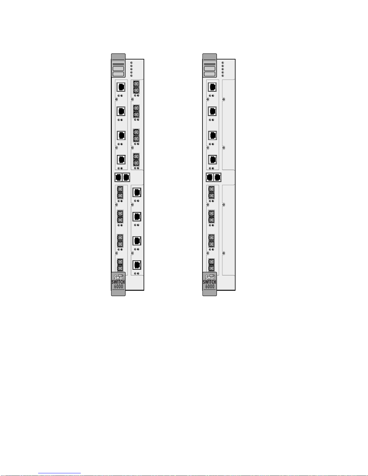
Depending on the configur ation ordered, your switch looks similar t o one of the units in the drawing i n Figure 2-1. The
6A000-04, shown on the left, has four I/O modules. The 6A000-02, shown on the right, has two I/O modules; the
empty I/O module positions are covered by metal blanks.
SmartCell 6A000 User Guide 2-1
Page 20
Inspectin
g
the Switch Switch Installation and Setup
ATM
FAIL
S
Y
STATUS
S
POWER
T
RX ENET
E
TX ENET
M
1234
1 2 3
NO SYNC
DATA
NO SYNC
DATA
6A-IOM-21-4
6A-IOM-22-4
AC
4
E
T
C
O
M
BD
H
E
R
N
E
T
123
NO SYNC
DATA
6A-IOM-21-4
1234
NO SYNC
DATA
6A-IOM-22-4
ATM
FAIL
S
Y
STATUS
S
POWER
T
RX ENET
E
TX ENET
M
1234
NO SYNC
DATA
6A-IOM-22-4
AC
E
T
C
O
M
BD
H
E
R
N
E
T
123
NO SYNC
DATA
6A-IOM-21-4
4
4
Figure 2-1 6A000-04 and 6A000-02 front panels
Inspect the switch and make certain that its configuration corresponds to what was ordered. Check the following:
Check the labels on operating software diskettes. Make sure they list the software package that was
ordered (ZX-SWR-PVC, ZX-SWR-SVC, or ZX-SWR-SVR). The software on the diskettes is the
software that comes factory installed on your switch.
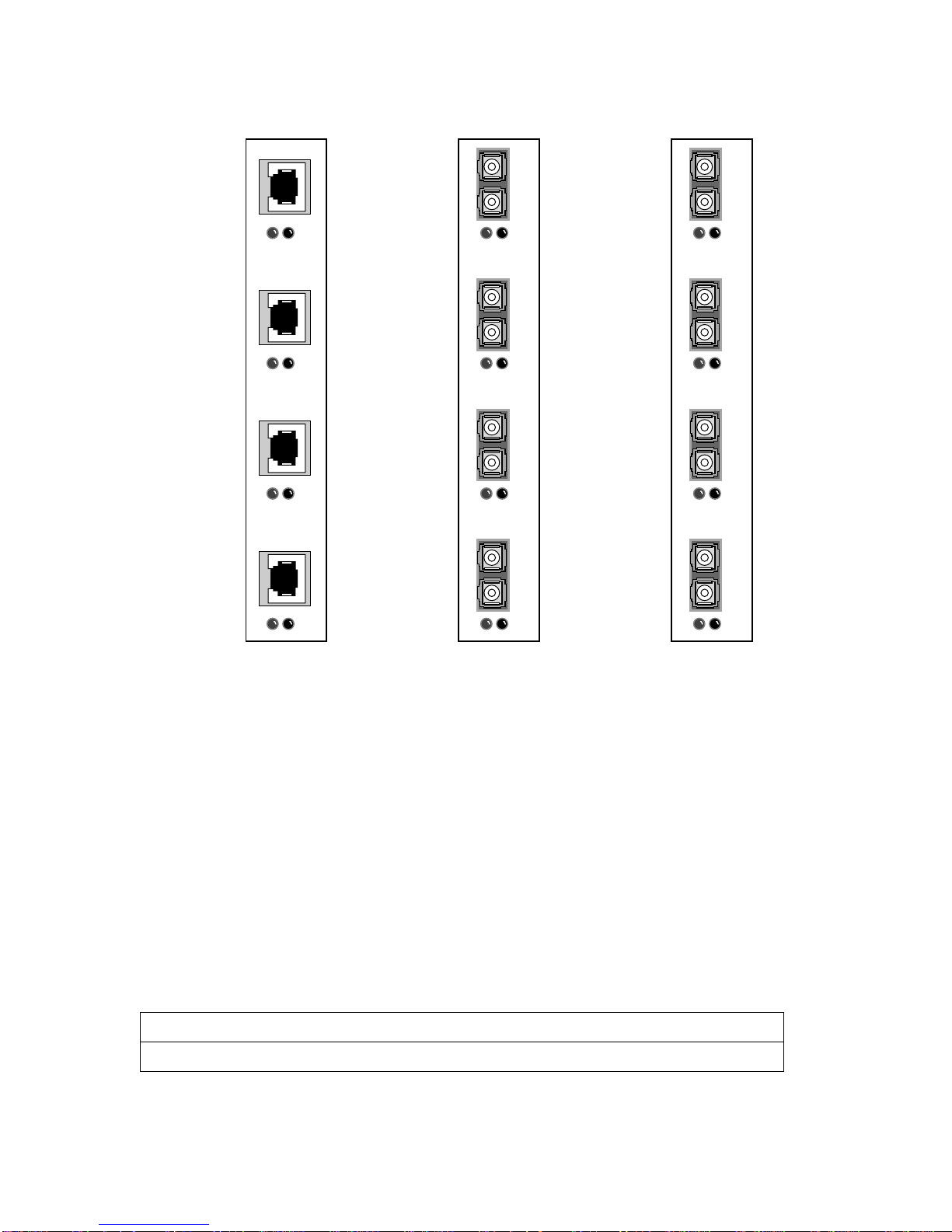
Input/Output (I/O) modules are of the correct type and number (See Figure 2-2).
2-2 SmartCell 6A000 User Guide
Page 21
Switch Installation and Setup Installin
g
SM
the Switch
NO SYNC
DATA
6A-IOM-22-4
1234
1 2 3 4
NO SYNC
DATA
6A-IOM-21-4
1 2 3 4
NO SYNC
DATA
6A-IOM-29-4
155 Mbps STS-3c/STM-1
UTP5, 4 Ports
155 Mbps STS-3c/STM-1
MMF, 4 Ports
155 Mbps STS-3c/STM-1
SMF/MMF, 4 Ports
Figure 2-2 6A000 I/O modules
If the hardware or software configuration is incorrect, contact Cabletron customer support immediately.
2.3 INSTALLING THE SWITCH
The SmartCell 6A000 is ho t swappa ble, mea ning th at you can i nstal l and r emove i t without turni ng of f or unp lugg ing
the SmartSwitch 6000 chassis. You can install as many as three switch mo dules in each chassis. In this configuration,
the SmartCell 6A000 modules provide up to 45 user ports. Modules should be connected with inter-module trunks if
traffic must cross between modules. T able 2-1 sho ws the maximum number of LAN and ATM switch modules that can
be installed in a SmartSwitch 6000 chassis.
Table 2-1 SmartSwitch 6000 contents
Number of 6Exxx or 6Hxxx modules installed012345
Number of 6A000 modules that can be added322100
SmartCell 6A000 User Guide 2-3
Page 22

Installin
g
the Switch Switch Installation and Setup
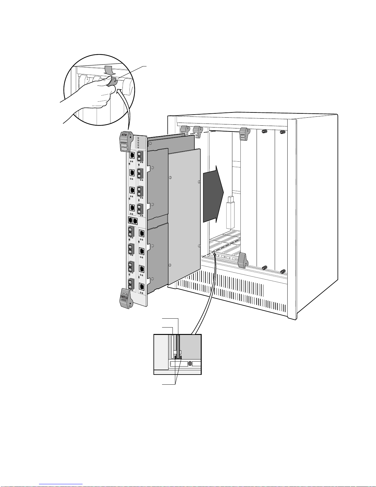
Follow the instructions below to ins tall the switch module into the chassis. Refer to Figure 2-3.
Remove the metal blank that covers one of the empty slots in the chassis.
Open the ejectors at the top and bottom of the switch module.
With the LEDs at the top, align the top and bottom of the SmartCell 6A000 with the tracks in the slot.
Slide the switch into the chassis. The switch module obscures the view of the tracks at the bottom of
the chassis, so be sure to look at that area as you begin to slide the switch into the chassis.
Close the ejectors. The installation is complete.
2-4 SmartCell 6A000 User Guide
Page 23
Switch Installation and Setup Installin
g
Rotate ejector
to lock in place
the Switch
Metal Backpanel
Figure 2-3 Installing the SmartCell 6A000
Circuit Card
Card Guides
SmartCell 6A000 User Guide 2-5
Page 24
Confi
g
g
uring the Switch Switch Installation and Setup
2.4 CONFIGURING THE SWITCH
Initial configuration of your SmartCell 6A000 switch consists of setting the name, Ethernet IP address, and subnet
mask. Once these tasks are complete done, the switch can be reached through your Ethernet network for additional
configuration and administration.
Perform the following steps to configure initial switch parameters:
Determine whether you will use a dumb terminal, workstation, or PC running termin al emulation
software to perform initial switch configuration.
Configure dumb terminals or PCs running emulation software with the following communication
parameters:
Baud rate = 9600
Data bits = 8
Stop bits = 1
Flow control = none
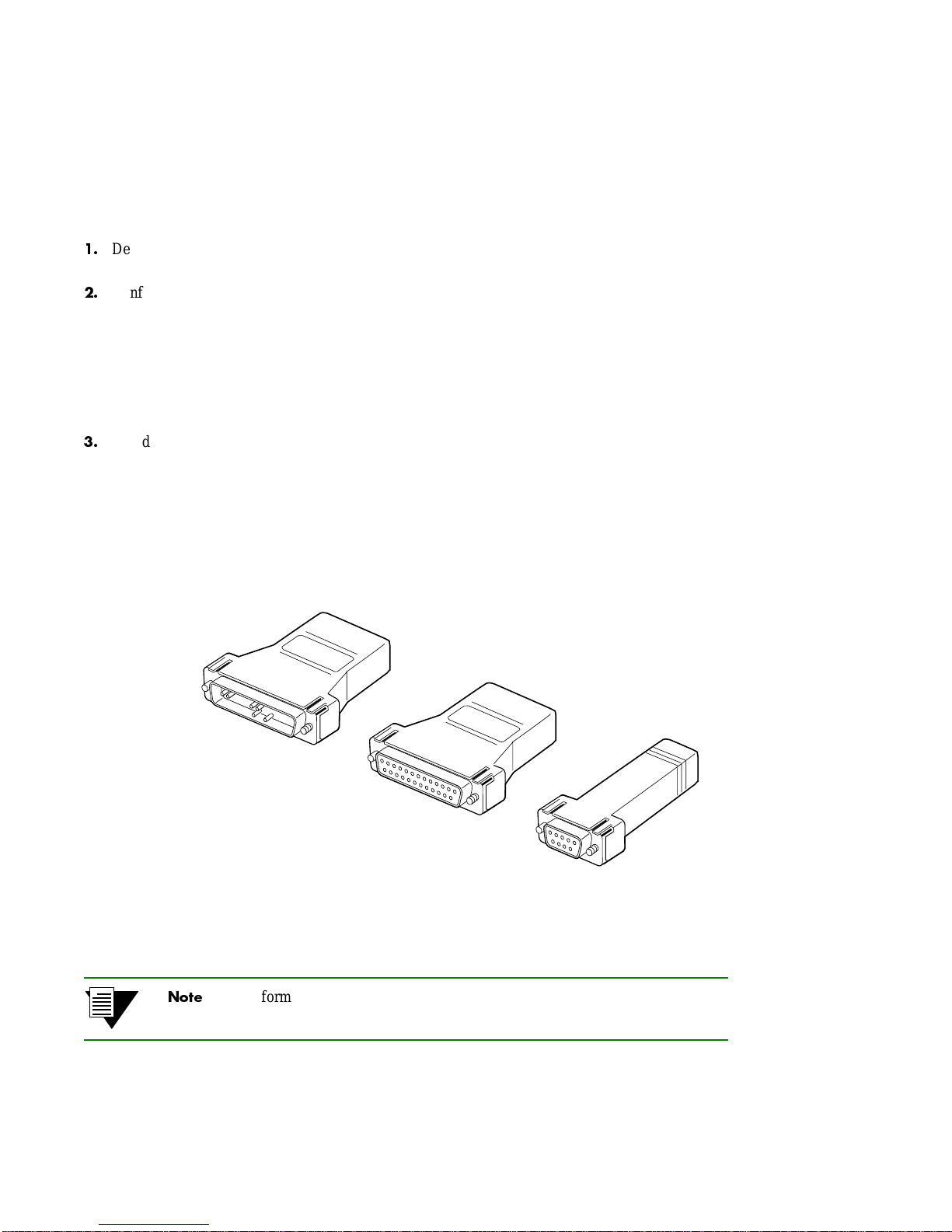
Based on your choice in 1, above, plug one end of the supplied RJ-45 UTP cable into the appropriate
RJ-45 adapter (see Figure 2-4)
Dumb terminal — converter labeled modem
PC with terminal software and 9-pin COM port — converter labeled PC
PC with terminal software and 25-pin COM port — converter labeled VT
UNIX workstation — converter labeled VT (you may also need a female-to-male gender changer)
DB-25 to RJ-45
Modem Adapter
Fi
ure 2-4 Adapters provided for connecting to the switch
2-6 SmartCell 6A000 User Guide
For information about adapter wiring configurations, see Appendix A, "Features
and Specifications."
DB-25 to RJ-45
VT Adapter
DB-9 to RJ-45
PC Adapter
Page 25
Switch Installation and Setup Confi
g
g
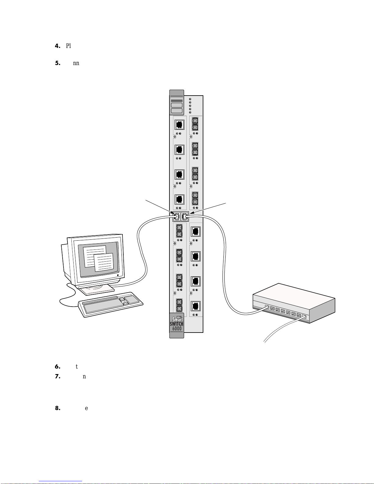
Plug the other end of the UTP cable i n to t h e S mar tC el l 6 A000 female RJ-45 jack l abel ed T e rminal ,
located on the front panel (see Figure 2-5).
Connect the switch to your network by plugging a UTP cable into the SmartCell 6A000 female
RJ-45 jack labeled Ethernet, located at the lower right of the switch's front panel (see Figure 2-5).
uring the Switch
Terminal
RJ-45
Port
ATM
FAIL
S
Y
STATUS
S
POWER
T
RX ENET
E
TX ENET
M
1 2 3
1234
NO SYNC
DATA
NO SYNC
DATA
6A-IOM-21-4
6A-IOM-22-4
4
Ethernet
RJ-45
Port
1 2 3
NO SYNC
DATA
6A-IOM-21-4
1234
NO SYNC
DATA
6A-IOM-22-4
Terminal
Fi
ure 2-5 6A000 console and network connections
Start the dumb terminal or PC and its terminal emulation software.
As soon as power is applied to the SmartCell 6A000, the module emits a series of diagnostic
messages. If you inserted the module into a chassis that was turned off, turn it on now to see the
diagnostics. If you inserted the module into a chassis that was turned on, press the Reset switch to
see the diagnostics.
After the diagnostics are finished, the switch prompts for a pas swo rd. Enter th e default password,
"admin."
4
Ethernet
Hub
SmartCell 6A000 User Guide 2-7
Page 26

Usin
g
the Console Switch Installation and Setup
Next, the switch prompts for the inform ation n ecessary to make the switch accessible through your
Ethernet network
Switch name
IP address
Subnet mask
After you enter these parameters and reboot the switch, log of f the local console connection. Perform
additional configuration steps over your network using a telnet connection.
Only one console connection is allowed at any time.You must exit the local
terminal connection by entering the
exit command. If you do not, the local
terminal session remains active and yo u cannot reach the switch thr ough telnet. T o
correct this condition, connect the local terminal to the switch and enter the
exit
command.
The following is an example of the initial configuration session:
SmartCell ZX Version 1.0(c) Cabletron Inc.
password:: admin <
The current user is Administrator
Could not find setup file
Running Setup Automatically
SwitchName() : My_6A000
IPAddress(0.0.0.0) : 210.160.77.254
IPNetMask(255.0.0.0) : 255.255.255.0
Confirm(y/n)?:y
Changing IP Address on System. Telnet session (if any) will be lost.
SmartCell ZX #
admin" is the default password
Before continuing to Chapter 3, "IP Over ATM and LANE," read the following sections to familiarize yourself with
the console of the SmartCell 6A000.
2.5 USING THE CONSOLE
Use the SmartCell 6A000 console interface to configure and ma nage your switch. The fo llowing is a description of the
console interface and its operation.
2.5.1 Console Commands
For detailed descriptions of console commands, see the SmartCell 6A000/ZX-250 Reference Manual.
All console commands use the syntax
operator switch-attribute [<parameter 1> <parameter 2>... <parameter n>]
Where the operator is one of the following:
show (alias = display): Show the current values used by a switch-attribute.
add (alias = create): Add a new instance of a switch-attribute.
delete (alias = remove): Delete an instance of a switch-attribute.
2-8 SmartCell 6A000 User Guide
Page 27

Switch Installation and Setup Usin
g
g
modify
(alias = set): Change the values that currently define a switch-attribute.
start: Start a process on the switch; for example, start the LAN Emulation Configuration Server.
restart: Restart a process on the switch; for example, restart a client.
flush: Remove assigned values; for example, flush a route table.
the Console
Entering parameters at the command line i s optional. If a command requires parameter values, it prompts you for them.
For instance, in the example below,
show is the operator, client is the switch-attribute, and 1 is the parameter
indicating that you want to show information abo ut "client 1 " .
SmartCell ZX # show client 1
LANE Client 1
===============================================================
Client State : Operational
Client Address : 39:00:00:00:00:00:00:00:00:00:14:41:80:00:20:D4:14:41:81:00
LAN Name : elan2
LECS Addr Source : ILMI
LECS Address : 39:00:00:00:00:00:00:00:00:00:14:41:80:00:20:D4:14:41:80:01
LES Address : 39:00:00:00:00:00:00:00:00:00:14:41:80:00:20:D4:14:41:82:02
LAN Type : 802.3
MTU : 1516
IP Address : 200.200.100.254
IP NetMask : 255.255.255.0
SmartCell ZX #
If you don't specify p aramet ers wit h the command, the console prom pts you for a choice and pro vi des a default value
displayed in par entheses. For ex ample, if you enter
show client without specifying a client (as a parameter), the
following appears:
SmartCell ZX # show client
ClientNumber(ALL) :
Here, the default of "all" clients is presented. You can either accept the default by pressing Enter, or you can enter a
specific client number. Accepting the default displays the following:
SmartCell ZX # show client
ClientNumber(ALL) :<Enter>
Client Type IP Address Server Type Server Conn Status
============================================================================
0 LANE 200.100.100.254 LECS Established Operational
1 LANE 200.200.100.254 LECS Established Operational
2 IP/ATM 200.50.50.254 Local Established Operational
3 IP/ATM 200.50.40.254 Local Established Operational
SmartCell ZX #
When you accept the (all) default for show, the information displayed is often
condensed.
Adding and Modifyin
The add and modify operators often need parameters. You can enter these parameters on the command line before
entering the command. If you don't enter the parameters, the switch prompts you for values.
SmartCell 6A000 User Guide 2-9
Page 28

Usin
g
the Console Switch Installation and Setup
As with the show command, each prompt provides you with a default. For example
SmartCell ZX # add laneclient
ClientNumber(3) :
LanName(ELAN003) : My-elan
ServerType(LECS) :
ServerAddress() : 39:00:00:00:00:00:00:00:00:00:14:41:80:00:20:d4:14:41:80:01
IPAddress() : 122.44.212.17
NetMask(255.0.0.0) : 255.255.255.0
MTU(1516) :
SmartCell ZX #
accept the defaul t
call the ELAN something other than the default name
In the example above, some values are specified by taking the default, while others are explicitly entered.
Press the Esc key to back out of any command before you enter the last value.
2.5.2 Console Help
The console provides several levels of help for console commands. For example, to list the switch-attributes that can
be used with a particular operator, enter the word
SmartCell ZX # help add
HELP ---- add
============================================================================
add [ AlarmConf | BUSELAN | Community | ELAN | IISPRoute |
IPATMClient | IPATMPVC | LANEClient | LECSAddress | LECSELAN |
LECSELANLEC | LECSTLVSET | LESELAN | PVC | Route |
TrafficDescriptor | TrapCommunity | UNIRoute | WellKnownAddress ]
SmartCell ZX #
To obtain an explanation of a command and its parameters, enter the word help (or ?) before the command.
SmartCell ZX # ? add laneclient
Create LANE Client
============================================================================
ClientNumber Local Client Number (0-127)
LanName Name of the ELAN to join
ServerType Type of LANE Server [LECS, LES]
ServerAddress ATM Address of the LANE Server
IPAddress IP Address of the Client
NetMask IP Netmask of the Client
MTU MTU for the Client [1516, 9234, NONE]
SmartCell ZX #
help (or ?) followed by the operator.
While entering a command, you can obtain help about the current parameter by entering a question mark (?) at the
prompt. For example
SmartCell ZX # add uniroute
PortNumber(A1) :B3
UNIATMAddress() : ?
ATM Address for the UNI route. 20 bytes
UNIATMAddress() :39:00:00:00:00:00:00:00:00:00:14:41:80:00:20:d4:14:41:80:00
SmartCell ZX #
2-10 SmartCell 6A000 User Guide
Page 29

3 IP OVER ATM AND LANE
This chapter explains how to set up a VLAN using classical IP over ATM and how to create an emulated LAN. After
reading this chapter, you will be able to use your SmartCell 6A000 switch to
• Create an IP over ATM VLAN
• Create an emulated Ethernet LAN using LAN emulation (LANE)
3.1 CREATING AN IP OVER ATM VLAN
This section describes how to implement IP over ATM on your SmartCell 6A000 switch. The following assumptions
are made:
• The Sm artCell 6A000 switch will have a client on the IP over ATM VLAN.
• The ARP server will reside on the switch and correspond to the address of the switch client.
• All end nodes (computers, edge devices, and so on) support switched virtual circuits (SVCs).
1. Log into the switch, either through the terminal port or through the Ethernet interface by telnet.
2. Create a client on the switch and assign it as the ARP server for the VLAN.
SmartCell ZX # add ipatmclient
ClientNumber(0) : 1
ServerType(NONE) : local
ServerAddress() :
IPAddress() : 90.1.1.1
NetMask(255.0.0.0) : 255.255.255.0
MTU(9180) :
SmartCell ZX #
assign the ARP server to the switch client
IP address is for example only
subnet mask is for exampl e onl y
The example above creates a client on the switch, designates the client as the ARP server for the VLAN (ServerType
= local), and assigns the client an IP address and subnet mask.
3. Enter the show client command to make sure the client is operational and to obtain the 20-byte
ATM address of the ARP server. For example, if you used the client number (client 1) from the
example in step 2
SmartCell ZX # show client 1
IP/ATM Client 1
============================================================================
Client State : Operational
Client Address : 39:00:00:00:00:00:00:00:00:00:14:41:80:00:00:5A:01:01:01:00
Server : is local
Server Connection : Established
MTU : 9180
IP Address : 90.1.1.1
IP NetMask : 255.255.255.0
SmartCell ZX #
4. Physically connect your end nodes and edge devices to the SmartCell 6A000 ports.
SmartCell 6A000 User Guide 3-1
Page 30

Note End nodes do not need to be physically attached to the switch that contains the
ARP server. For example, an end station is connected to a SmartCell 6A000
switch that is connected through an IISP route to the switch containing the ARP
server. No special con figuration is need ed for this end station to par ticipate in the
VLAN because the end station automatically finds its path across the IISP route
to communicate with the ARP server and the other VLAN members.
5. Configure the ATM interface or adapter for end nodes and edge devices. Typically, configuration
consists of designating IP over ATM as the protocol, assigning the device an IP address, and
specifying the 20-byte ATM address of the ARP server (the switch's client address).
6. As your end devices are configured and started, they register with the ARP server. You can test
whether your IP over ATM VLAN is functional by pinging from o ne end device to another.
7. To make cer tain that all end devices are registered with the ARP server, you can inspect the switch's
ARP table using the
show ipatmarp command. For example, if three end devices with IP addresses
90.1.1.2, 90.1.1.3, and 90.1.1.4 are added to the VLAN, the following ARP table entries should
exist:
SmartCell ZX # show ipatmarp
ClientNumber(ALL) :
IP/ATM Server 1 ARP Table
IP Address ATM Address
============================================================================
90.1.1.2 39:00:00:00:00:00:00:00:00:00:14:41:80:00:00:5A:01:01:02:00
IP/ATM Server 3 ARP Table
IP Address ATM Address
============================================================================
90.1.1.3 39:00:00:00:00:00:00:00:00:00:14:41:80:00:00:5A:01:01:03:00
IP/ATM Server 5 ARP Table
IP Address ATM Address
============================================================================
90.1.1.4 39:00:00:00:00:00:00:00:00:00:14:41:80:00:00:5A:01:01:04:00
SmartCell ZX #
3.1.1 ATM Addressing for IP over ATM
The SmartCell 6A000 uses a default form for ATM addresses in IP over ATM. The default format is constructed as
follows:
netprefix + two zero bytes + IP address of the device (in hex) + a trailing zero byte
Where the netprefix is constructed from
39 + nine zero bytes + the last three bytes of the device's MAC address
For instance, if the switch MAC address is 00:20:D4:14:41:80 and its client IP address is the one used in the example
in step 2, then the 20-byte ATM address of the ARP server is
39:00:00:00:00:00:00:00:00:00:14:41:80:00:00:5A:01:01:01:00
Where
• 39:00:00:00:00:00:00:00:00:00:14:41:80 = netprefix
• 00:00 = two trailing zeros
3-2 SmartCell 6A000 User Guide
Page 31
• 5A:01:01:01 = IP address 90.1.1.1 in hexadecimal
• 00 = trailing zeros byte
3.2 CREATING AN EMULATED LAN
This section describes the steps for implementing an Ethernet or Token Ring Emulated LAN (ELAN) on your
SmartCell 6A000 switch. The following assumptions are made:
• The switch will contain a client on the ELAN.
• The switch uses the ATM Well Known LECS Address for the address of its LAN Emulation
Configuration Server (LECS).
• All end nodes (computers, edge devices, and s o on ) s up por t the Well Known LECS Address or can
obtain the address of the LECS using ILMI.
• All end nodes support Switched Virtual Circuits (SVCs).
Note An ELAN (including local client) comes preconfigured on SmartCell 6A000
switches running server software. The ELAN name is "ELAN000" and the local
client number is zero (0). To use ELAN000, configure your end nodes and edge
devices to use this ELAN, and then plug them into the switch.
1. Map the Well Kno wn LECS Address to the address of the SmartCell 6A000 LECS by executing the
add wellknownaddress command
SmartCell ZX # add wellknownaddress
WellKnownAddress(47:00:79:00:00:00:00:00:00:00:00:00:00:00:a0:3e:00:00:01:00):
RegisteredAddress(39:00:00:00:00:00:00:00:00:00:14:41:80:00:20:D4:14:41:80:01):
SmartCell ZX #
The first ATM address in the example above is the Well Known LECS Address, the second (supplied as a default) is
the ATM address of this switch's LECS.
Note The Well Known LECS Address is an ATM Forum standard, supported by many
ATM devices. The configuration sof tware of th ese devices pr ovides a simple way
(for instance, a dialog box butt on) for selecting the Well Known LECS Address as
the address of the LECS. If your end devices use the Well Known LECS Address,
it is unnecessary to enter the 20-byte LECS address by hand.
Note It is unnecessary to specify the LECS address if your end devices support
discovery of the LECS through ILMI.
SmartCell 6A000 User Guide 3-3
Page 32

2. Create an ELAN on your switch by executing the add elan command. The following is an example:
SmartCell ZX # add elan
ELANNumber(0) : 1
ELANName(ELAN000) : Marketing
ConnectMethod(SVC):
ELANType(802.3)
Multipoint(YES) :
MTU(1516) :
Distribute(PROXY) :
SmartCell ZX #
use 1 instead of the default, (0)
< The default (Ethernet) is used
ELAN is named Marketing i nste ad of the default, (ELAN000)
3. Create a client for the switch on the ELAN. For example, enter
SmartCell ZX # add laneclient
ClientNumber(0) : 1
LanName(ELAN001) : Marketing
ServerType(LECS) :
ServerAddress() :
IPAddress() : 90.1.1.1
NetMask(255.0.0.0): 255.255.255.0
MTU(1516) :
SmartCell ZX #
NOTICE - 'ZLESSRV' LES Join 39:00:00:00:00:00:00:00:00:00:14:41:80:00:20:D4:
14:41:82:00
NOTICE - 'ZLESSRV' BUS Connect 39:00:00:00:00:00:00:00:00:00:14:41:80:00:20:D4:
14:41:82:00
< one is used instead of the default, (0)
< ELAN name is Marketing, not the def aul t , (E LAN001)
< IP address and subnet mask is assigned to the client
Note When you create a client, it automatically finds the LECS address using ILMI.
Notice that as the newly created client becomes active, messages appear on the console indicating that the client has
registered with the LAN Emulation Server (LES) and the Broadcast and Unknown Sever (BUS).
4. Enter the show client command to make certain that the client is operational.
SmartCell ZX # show client 1
LANE Client 1
============================================================================
Client State : Operational
Client Address : 39:00:00:00:00:00:00:00:00:00:14:41:80:00:20:D4:14:41:81:00
LAN Name : Marketing
LECS Addr Source : ILMI
LECS Address : 39:00:00:00:00:00:00:00:00:00:14:41:80:00:20:D4:14:41:80:01
LES Address : 39:00:00:00:00:00:00:00:00:00:14:41:80:00:20:D4:14:41:82:02
LAN Type : 802.3
MTU : 1516
IP Address : 90.1.1.1
IP NetMask : 255.255.255.0
SmartCell ZX #
Note While creating an ELAN client for the switch is not absolutely necessary, it does
provide management connectivity with the switch over its ATM ports (instead of
the Ethernet port). See Chapter 4, "Switch Administration."
5. Physically connect your end nodes and edge devices to the switch ports.
3-4 SmartCell 6A000 User Guide
Page 33
6. Configure the A T M interface or adapter for all end nodes and edge dev ices. T ypically, configuration
consists of specifying LAN Emulation as the protocol, assigning the device an IP address that
corresponds to the subnet of the switch's client, and indicating that you want the device to use the
Well Known LECS Address or the ILMI acquired LECS address as the address for the LECS.
7. Messages are displayed on the console as each end device registers with the LES and BUS. You can
check connectivity by pinging between end nodes.
Your ELAN is now op erational. Additional ELANs can be created in the same way. See Chapter 4, "Switch
Administration." for information about SmartCell 6A000 switch operations and maintenance.
Note While it is possible for a single ELAN on the SmartCell 6A000 switch to support
multiple subnets, in general, switch performance is best and management easiest
when the "One-subnet-per-ELAN" rule is observed.
3.2.1 ATM Addressing for LAN Emulation
The SmartCell 6A000 provides a default format for ATM addresses used by LAN emulation. The default format is
constructed as follows:
netprefix + the MAC address of the device + a Selector Byte
Where the netprefix is constructed from
39 + nine zero bytes + the last three bytes of the switch's MAC address
The Selector Byte specifies to whom the ATM address belongs.
• 00 = LEC
• 01 = LECS
• 02 = LES or BUS
For instance, if the switch's MAC address is 00:20:D4:14:41:80, then the 20-byte ATM address of the LECS is:
39:00:00:00:00:00:00:00:00:00:14:41:80:00:20:D4:14:41:80:01
Where
• 39:00:00:00:00:00:00:00:00:00:14:41:80 = netprefix
• 00:20:D4:14:41:80 = the switch's MAC address
• 01 = the Selector Byte indicating that this is the LECS
Additionally, within both the LES and BUS addresses, the byte that corresponds to the last byte of the MAC address
is summed with the ELAN number. For example, the ATM address of the LESs on ELAN000, ELAN001, and
ELAN010 are
• LES for ELAN000 = 39:00:00:00:00:00:00:00:00:00:14:41:80:00:20:D4:14:41:80:02
• LES for ELAN001 = 39:00:00:00:00:00:00:00:00:00:14:41:80:00:20:D4:14:41:81:02
• LES for ELAN010 = 39:00:00:00:00:00:00:00:00:00:14:41:80:00:20:D4:14:41:8A:02
SmartCell 6A000 User Guide 3-5
Page 34
3.2.2 ELANs Across Multiple Switches
ELANs can exist within a single switch or they can span multiple switches through IISP routes. When an ELAN spans
multiple switches, it's important that all switches within the group use the same LECS. The general rule is "Within an
administration domain (a group of switches with related ELANs), there should be exactly one LECS."
To assure that there is only one LECS, you can take one of the following actions:
1. Turn off the LECS using the stop lecs command on all but one switch. The switch with the LECS
left running provides LECS support for the rest of the group. Use the
on all the other switches so that they point to the switch with the running LECS for LECS support.
2. Use the add wellknownaddress command on all other switches to map the Well Known LECS
Address to the LECS address of the switch with the running LEC S. Now, all devices and clients
configured to use the Well Known LECS Address automatically register with the switch with the
running LECS.
Note Use IISP routing to connect multiple SmartCell 6A000 switches to form
administration do mains. See Chapter 4, "Switch Administ ration." for in formation
on setting up IIS P routes.
set lecsaddress command
3.2.3 Switch Clients
The concept of SmartCell 6A000 switch client conn ections is an important co ncept to understan d. A client connection
is actually a connection between the VLAN and the SmartCell 6A000 CPU; this CPU connection appears as if the
switch is an end station on the VLAN. The SmartCell 6A000 uses lo cal clients to connect itself to the VLANs that it
supports.
This is analogous to a phone company that supports a communication system. Even though the phone company
maintains the circu its, a call to the phone company itself cannot be made unless the phone company has its own number
and connection on its own phone system. Similarly, VLAN membership (and reachability) of a SmartCell 6A000 on
any particular VLAN depends upon whether the SmartCell 6A000 has a local client connection for that VLAN.
Clients are created using the
For example, the following adds a switch LANE client to the ELAN elan1:
SmartCell ZX# add laneclient
ClientNumber(0) : 1
LanName(ELAN001) : elan1
ServerType(LECS) :
ServerAddress() :
IPAddress() : 128.213.77.95
NetMask(255.255.0.0) :
MTU(1516) :
SmartCell ZX#
Prior to creating this local client connection, end devices could communicate with each other throu gh elan 1, b ut they
could not communicate with the SmartCell 6A000.
add laneclient command for LAN emulation, and add ipatmclient for IP over ATM.
3-6 SmartCell 6A000 User Guide
Page 35

4 SWITCH ADMINISTRATION
This chapter contains software and hardware procedures that you might need to perform on your SmartCell 6A000
switch. These procedures include
• Backing up and restoring switch configur ation
• Upgrading switch operating software
• Creating routes and connecting switches
• Using switch logs and alarms
4.1 BACKING UP AND RESTORING SWITCH
CONFIGURATION
Once your SmartCell 6A000 ATM switch is up and running or yo u have made extens ive changes to the con figuratio n,
you should back up the swi tch configu ration. If the flash RA M gets formatte d or corrupted , you can rest ore the swit ch
configuration from the backup file.
Note The backup command backs up only the configuration files. It does not back up
an image of the operating software.
To perform a back up or restore, you must have TFTP server software running on an end station connected to the
switch. The
software. Often, this directory is /tftpboot; however, it may be different with your TFTP server software. Backup file
names can be anything. Both the target backup directory and its file must exist and have appropriate read and write
permissions for the backup to complete successfully.
The
backup command prompts you for the IP address of the TFTP server end station, the backup path, and the name
of the file within which you are saving the configuration. For example, if the IP address of the TFTP server end station
is 90.1.1.100, and y ou want to s ave the switch configur ati o n i n th e fi le n amed config-1 under the direct ory / back _di r,
enter the following:
SmartCell ZX# backup switch
ServerIP() : 90.1.1.100
Path() : /back_dir/config-1
SmartCell ZX #
backup command copies the configuration files on the switch to a directory specified by the TFTP server
SmartCell 6A000 User Guide 4-1
Page 36

Up
g
rading Operating Software Switch Administration
The switch stores the IP address of the TFTP server, the path, and the backup file name. The next time you enter the
or restore commands, these values are presented as the default IP address and path. For example, when you
backup
enter the
SmartCell ZX# restore switch
ServerIP(90.1.1.100) :
Path(/back_dir/config-1) :
SmartCell ZX #
Backup file is valid.
Restoring a backup file will completely replace any data stored in the flash.
Are you sure this is what you want to do?
Confirm(y/n)?: y
SmartCell ZX #
restore command, the following display appears:
Note You must reboot the switch for the restore to take effect.
4.2 UPGRADING OPERATING SOFTWARE
You can upgrade the operating software of the SmartCell 6A000 while the switch is running its current software. This
procedure is known as a hot upgrade and is accomplished by the
update firmware command.
When the switch is started (or rebooted), it copies its operating software from flash RAM to the CPU program memory.
When you perform a hot upgrade, the image in flash RAM is erased and replaced with the new software image. While
the upgrade is occurring, the switch continues to run the copy in program memory. When the switch is rebooted, the
new software image residing in flash RAM is copied into system memory and then run.
T o use the hot upgrad e feature, the switch mu st have network access to an end station runn ing TFTP server software.
The SmartCell 6A000 operating software file must reside within th e directo ry specified b y th e TFTP server software.
Often, this directory is /tftpboot. However, it may be different with your TFTP server software.
The following is an example of a hot upgrade:
SmartCell ZX # update firmware
ServerIP() : 128.95.77.210
Path() : server.ima
You are updating the code image in the flash.
Are you sure this is what you want to do?
Confirm(y/n)?:y
Erasing Flash.
Using TFTP to get and program bootfile server.ima from 128.95.77.210.
2672K |
2737100 bytes received.
Image Updated.
You will have to reboot for the new image to take effect.
SmartCell ZX #
Notice that the update firmware command does not use bootp to find the TFTP server. Instead, the update firmware
command requires that you specify the IP address of the TFTP server, the path to the image file, and the file name.
4-2 SmartCell 6A000 User Guide
Page 37

Switch Administration Settin
g
Up Routes
4.2.1 Unsuccessful Update
If the update firmware command fails, DO NOT turn off or attempt to reboot the SmartCell 6A000 switch. In its
current state, the operating software normally stored in flash RAM is erased. The switch is still functioning on ly
because it is running the image of the operating software that resides in volatile system memory.
If possible, determine why the
update firmware command failed. Common causes for failure are
• Incorrect path and file names
• Improper permission settings on the directory containing the upgrade software
• SmartCell 6A000 is not physically connected to the network
• SmartCell 6A000 cannot reach the TFTP server subnet
If you can correct the problem, enter the
if you are unable to correct the problem, use the
operating software. Follow the procedure described in the next section.
update firmware command to continue with the upgrade process. However,
df (download flash) command and a tftpboot server to replace the
4.2.2 Using the df Command to Recover
1. Set up bootp server software on a workstation.
2. Connect both the bootp server workstation and the SmartCell 6A000 to your Ethernet network.
Make certain that the bootp server can be reached by the SmartCell 6A000.
3. Connect a dumb terminal (or PC running terminal emulation software) to the SmartCell 6A000
Terminal port.
4. Copy the SmartCell 6A000 operating software image into the appropriate location on the bootp
server.
5. Setup the bootp server tables (or equivalent) with the MAC address of the SmartCell 6A000, a
unique IP address, and the image software path.
6. From the terminal connection, enter the reboot command.
7. When the switch begins its seven-second countdown, stop it by pressing any key.
8. Enter the df command. The SmartCell 6A000 contacts the bootp server and downloads the operating
software into its flash RAM.
Press any key to exit to debug monitor. Waiting for 07 seconds...
06
05 <CR>
=>df
Are you sure?(Y/N)y
Initializing Ethernet...
Starting Bootp...
9. Enter the go command to start the SmartCell 6A000 in normal operating mode. The command
console login prompt appears as the switch runs its operating software.
4.3 SETTING UP ROUTES
The SmartCell 6A000 ATM switch supports several types of routing, each used for different purposes. Route protocols
supported are: IISP, UNIRoute, and IP routing.
SmartCell 6A000 User Guide 4-3
Page 38

Settin
g
g
Up Routes Switch Administration
4.3.1 IISP Ro utin
IISP routing connects t wo or more switches (or oth er devices). Through SVCs, IISP routes create u ser-transparent links
over which IP over ATM and LANE members can operate with each other and their respective support servers (ARP
server, LECS, LES, and so on). For example, if a VLAN spans two or more switches, all nodes in the VLAN can
communicate with the ARP server and with each other if the switches are connected using IISP routes.
Creating IISP Routes
Use the add iisproute command to create IISP routes. IISP routes are defined on each switch by the port number
through which the route exists and the netprefix of the switch at the opposite end.
For example, to set up an IISP route between port A4 on switch SW1 and port A4 of SW2, you would perform the
following steps.
1. Physically connect port A4 of switch SW1 to port A4 of switch SW2.
2. If the netprefixes of port A4 on SW1 and port A4 on SW2 are not already known, enter the show
netprefix
For switch SW1, enter:
SmartCell ZX # show netprefix a4
Port# NetPrefix
============================================================================
A4 39:00:00:00:00:00:00:00:00:00:14:41:80
SmartCell ZX #
For switch SW2, enter
SmartCell ZX # show netprefix a4
Port# NetPrefix
============================================================================
A4 39:00:00:00:00:00:00:00:00:00:14:47:80
SmartCell ZX #
3. Enter the add iisproute command on each switch.
command on each switch.
<SW1's netprefix for port A4
<SW2's netprefix for port A4
From SW1, enter
SmartCell ZX # add iisproute
ATMAdress() : 39:00:00:00:00:00:00:00:00:00:14:47:80
PortNumber(A1) :a4
Metric(1) :
SmartCell ZX #
<Specify A4 as the port
<SW2's netprefix
From SW2, enter
SmartCell ZX # add iisproute
ATMAdress() : 39:00:00:00:00:00:00:00:00:00:14:41:80
PortNumber(A1) : A4
Metric(1) :
SmartCell ZX #
<Specify A4 as the port
4. To see if the IISP routes exist, use the show iisproute command on each switch.
From SW1, enter
SmartCell ZX # show iisproute
Entry# Port# Metric Len Address
============================================================================
0 A4 1 104 39:00:00:00:00:00:00:00:00:00:14:47:80
SmartCell ZX #
4-4 SmartCell 6A000 User Guide
Page 39

Switch Administration Settin
g
Up Routes
From SW2, enter
SmartCell ZX # show iisproute
Entry# Port# Metric Len Address
============================================================================
0 A4 1 104 39:00:00:00:00:00:00:00:00:00:14:41:80
SmartCell ZX #
5. If clients on both switch SW 1 and SW2 are within the same subnet, you can test conn ectivity by
pinging between clients.
IISP Routes Among Multiple Switches
Multiple IISP routes can be set up over a single physical link. Continuing with the example above, a third switch (SW3)
is added.
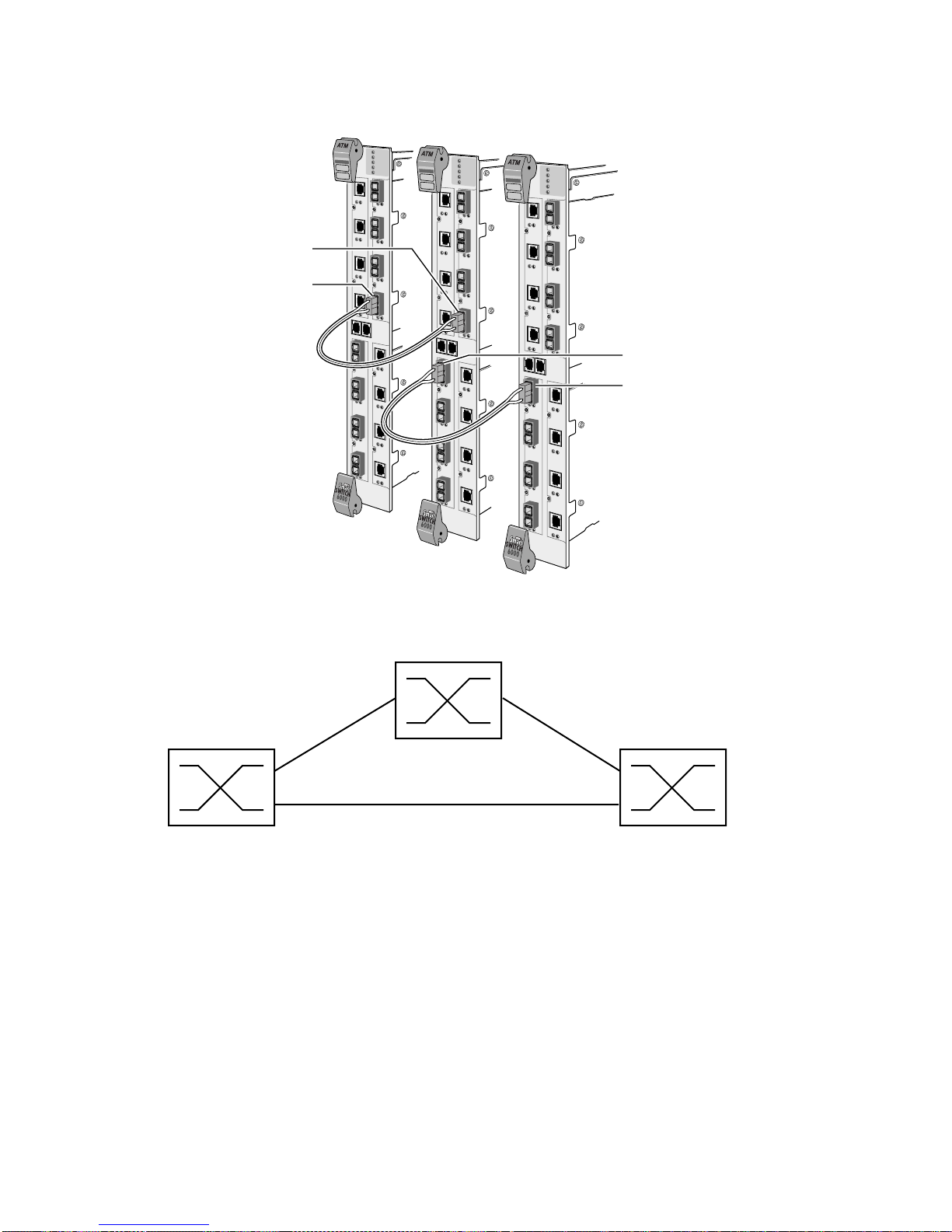
6. Connect a cable between port B1 of SW2 and port B1 of SW3; then add an IISP route between B1
of SW2 and B1 of SW3 (see Figure 4-1).
7. Use the add iisproute command to add a third route from SW1 to SW3 over the existing cables.
On switch SW1, enter:
SmartCell ZX # add iisproute
ATMAdress() : 39:00:00:00:00:00:00:00:00:00:14:15:00
PortNumber(A1) :a4
Metric(1) :
SmartCell ZX #
<Port on SW1 atta ched to the cable from A4 on SW2
<SW3's netprefix
On switch SW3, enter
SmartCell ZX # add iisproute
ATMAdress() : 39:00:00:00:00:00:00:00:00:00:14:41:80
PortNumber(A1) :b1
Metric(1) :
SmartCell ZX #
< Port on SW3 attached to the cable from B1 of SW2
<SW1's netprefix
SW1 and SW3 are connected without using a dedicated physical connection between the two switches.
Note that a routing loop is created if SW1 and SW3 are physically connected with a cable and an IISP route is defined
over this physical link.
SmartCell 6A000 User Guide 4-5
Page 40
Settin
g
Up Routes Switch Administration
Port C4
Port C4
Port B1
Port B1
Route 1 Route 2
39:00:00:00:00:00:00:00:00:00:14:47:80
39:00:00:00:00:00:00:00:00:00:14:41:80
Figure 4-1 IISP routes between multiple switches
Default IISP Routes
SW1
SW2
SW3
Physical View
Route 3
39:00:00:00:00:00:00:00:00:00:14:15:00
Logical View
A default route is a special IISP route that does not specify the netprefix of the destination port. The correct addressing
is worked out using IISP signaling between the SmartCell 6A000 and the device at the other end of the route. The
destination of a default IISP route can be a standard (addressed) IISP route or another default IISP route.
4-6 SmartCell 6A000 User Guide
Page 41

Switch Administration Settin
g
gy
Up Routes
For example, create a default IISP route from port B1.
SmartCell ZX# add iisproute
AtmAddress() :
PortNumber(A1) : b1
Metric(1) :
SmartCell ZX#
< no netprefix specified
To see the route in the SmartCell 6A000 routing table, enter the following:
Top # show iisp
EntryNum PortNum Metric Length ATM Address
============================================================================
0 B1 1 0 default route
SmartCell ZX#
Default IISP routes are used primarily as gateway connections to other LAN segments or to a WAN connection. For
instance, a SmartCell 6A000 contains four standard IISP routes and one default IISP route. If a connection is being
established whose address does not correspond to one of the four standa rd IISP routes, the conn ection is automaticall y
forwarded to the default IISP route.
Because of the default IISP route's lack of a definite ATM address, be careful when using these routes. Observe the
following rules when using default IISP routes:
• Never add more than one default IISP route on any SmartCell 6A000.
• Do not use default IISP routes as an "easy" way to create a route between two devices.
• Do not over use default IISP routes. Doing so can create overly complicated network topologies.
• When using IISP routes, be careful not to create ambiguous routes or routing loops.
• Restrict the use of default IISP routes to gateway connections out of the local LAN segment.
IISP Routes and Network Topolo
IISP is implemented on the SmartCell 6A000 switch so th at a route's destination address is some sequential portion
(always starting with the first byte) of a 20-byte ATM address. Usually, the default netprefix is used (first thirteen
bytes). However, routes can be defined using more or fewer bytes than the thirteen netprefix bytes.
This ability to define destination addresses by masking off portions of an ATM address allows multiple SmartCell
6A000 switches to be connected in flex ible co nfig uration s. Furth ermor e, you can change the netprefix of a switc h (or
a port on a switch) to any value by using the
set netprefix command. Combining these two capabilities, you can
define routes with simple addressing schemes and create hierarchical network topologies.
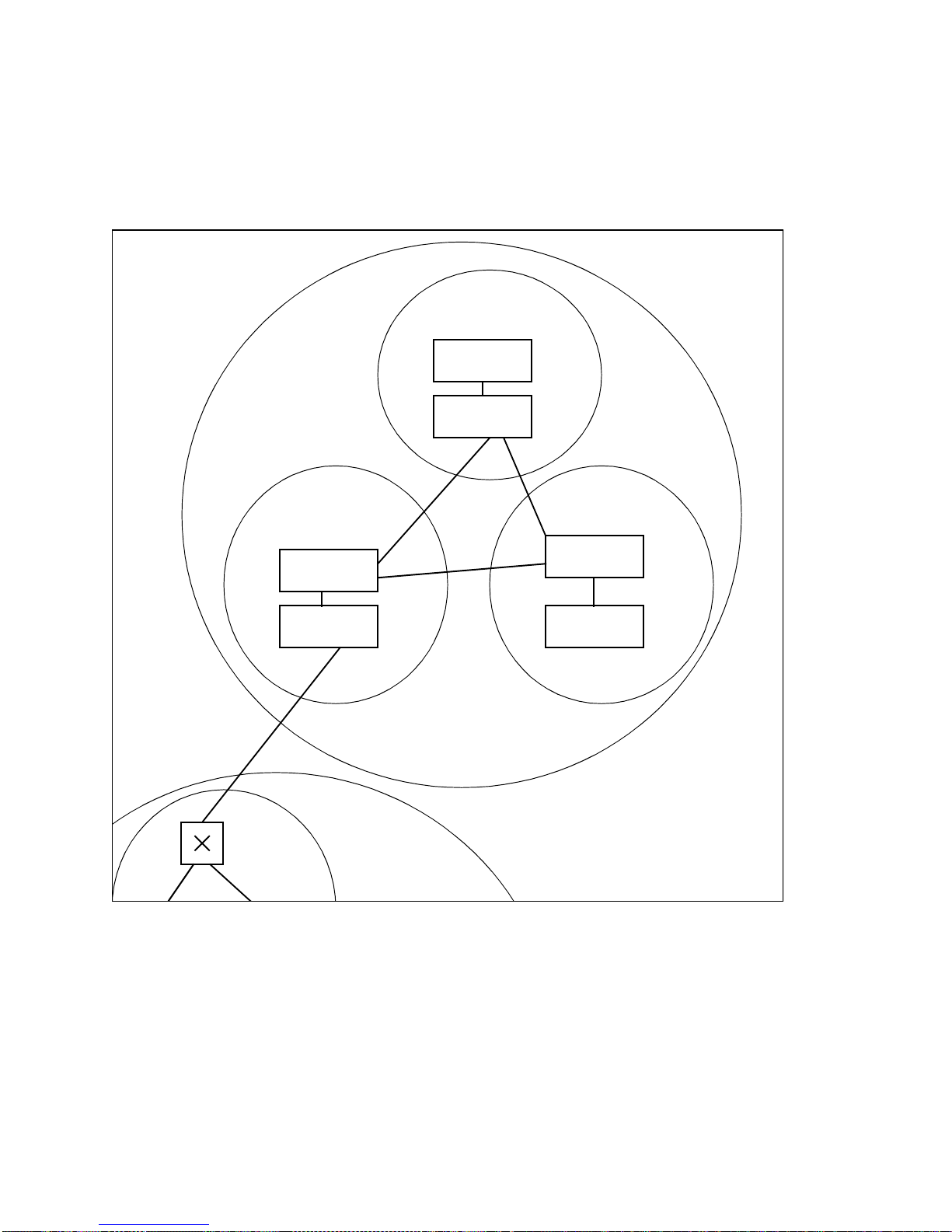
For example, Figure 4-2 shows three groups of switches: A, B and C. Use the
set netprefix. command to change
the first two bytes of the netprefix for switches within A, B, and C to 11:22.
Add a third byte to the netprefix of each group (a group identifier), such that
• Group A = 11:22:33
• G roup B = 11:22:44
• G roup C = 11:22:55
Within each grou p, add one more byte to each switch address (a switch identifier). Each switch (route destination) can
now be specified by
11:22: + group identifier byte + switch identifier byte
For example, switches in group A are 11:22:33:00 and 11:22:33:01
SmartCell 6A000 User Guide 4-7
Page 42
Settin
g
g
Up Routes Switch Administration
IISP routes between A, B, and C can be defined by
11:22: + group identifier byte
Collectively , groups A, B, and C represent the super-group "A-B-C. " Any group from o utside A-B-C can define a rou te
to A-B-C by using just 11:22.
11:22:33
11:22:55:01
11:22:55:00
super-group
C
11:22:33:00
11:22:33:01
=
11:22:
A
11:22:4411:22:55
11:22:44:01
B
11:22:44:00
Fi
ure 4-2 Hierarchical network design using netprefixes and IISP routes
Routing Loops
Be careful not to create "ambiguous routes" ( that is, routes defined by too f ew bytes). For i nstance, if a route is define d
within the super-group A-B-C by specifying 11:22 as the destination, a routing loop is created. An additional byte is
necessary to specify to which group (A, B, or C) the destination belongs.
4-8 SmartCell 6A000 User Guide
another
super-group
Page 43

Switch Administration Settin
g
g
g
Up Routes
IISP Metrics and Load Sharin
You can assign a metric value to each IISP route. The metric "weights" one route against another. The IISP metric
specifies which of two or more routes is used the most for setting up calls. Counters are set up for each route that equal
the route's metric. These counters are decremented as calls are set up through the routes. When a ro ute's counter reaches
zero, that route is not used until all other router counts reach zero, and all router counters are reset to their metric value.
Obviously, the route with the lowest metric decrements to zero first and remains unused until all other routes also
decrement to zero.
For example, two parallel routes are set up for redun dan cy and for load sharing between two switches. One route (A)
has a metric of one, while the other route (B) has a metric of two. This means that for every call set up through A, two
calls are set up through B.
The exception to the example above occurs when one of the parallel routes uses more bytes of the ATM address to
define the route destination. If true, the path through the route with the longer destination address is always selected
first.
For example,
If routes A and B are parallel and are defined by
A = port A1, port address: 11:22:33, and metric 3
B = port B1, port address: 11:22:33:44:55, and metric 1
B is always favored for use over A and is used as often as possible, regardless of the fact that it has a smaller metric
than A.
SigConfig and PortAutoDetect with IISP Routin
The SmartCell 6A000 and the device to which it is connect ed must bo th use th e same signali ng type: UNI 3.0 or UNI
3.1. Use
device on the other end of the connection. You also can use
modify sigconfig currentinterfacetype or defaultinterfacetype to set the interface type to match the
modify portautodetect to turn on auto detection of
signaling type, so the SmartCell 6A0 00 will sense the signaling type of the other device and use the same type.
IISP route signaling exp ects on e end of the route to adopt us er beh a vior and the other end to adopt net work behavior .
However, some devi ces to whic h you con nect your Sm artCell 6A0 00 switch may be incapab le of ne gotiating which is
network and which is user. If a device is unable to negotiate, use the
defaultinterfacerole
parameter of the modify sigconfig command to set the port on the switch to the behavior
currentinterfacerole or
opposite to that of the connected device.
4.3.2 UNI Routes
Use static UNI routes when a device being connected to the SmartCell 6A000 switch either does not support ILMI or
whose implementation of ILMI is incomp atible with the SmartCell 6A000.
Use the
add uniroute command to add static routes to the UNI route table of the switch.
For example, to add to port A1 a static UNI Route that connects to a device with ATM address
44:00:00:00:00:00 :00: 0 0: 00: 0 0:14 :4 1: 80 :00: 30 : E5: 14 :4 1: 80 : 00, ente r the followi ng :
SmartCell ZX # add uniroute
PortNumber(A1) :
UNIATMAddress() : 44:00:00:00:00:00:00:00:00:00:14:41:80:00:30:E5:14:41:80:00
SmartCell ZX #
SmartCell 6A000 User Guide 4-9
Page 44
Settin
g
g
Up Routes Switch Administration
To see whether the static uniroute has been added, list the routes using the show uniroute command.
Note Some devices require ILMI to be disabled for UNI routes to work. Use the set
ilmiadminstatus command to disable ILMI on the SmartCell 6A000 switch on a
per-port basis.
4.3.3 IP Routin
The SmartCell 6A000 switch provides limited IP routing. IP routing allows switches that are not connected directly to
Ethernet to communicate with an Ethernet-based network management system (NMS). The connection is made by
adding IP routes on the non-connected switches that specify a client on a connected switch as their gateway to the
Ethernet.
Note SmartCell 6A000 IP routing performance is inadequate for routing between
VLANs. If you need to create routes between VLANs on your SmartCell 6A000,
use a router equipped with an ATM interface. Consult Cabletron Customer
Support for recommended routers.
For example,
• Switch SW1 and the NMS are on an Ethernet network with address 128.205.99.0.
• The IP address of SW1's Ethern et port is 128.205.99.254.
• The IP address of SW1's LANE client is 90.1.1.254.
• The IP address of SW2's LANE client is 90.1.1.33.
• SW 2 is not physically connected to the Ethernet network.
• SW 2 is connected to SW1 through an IISP route, and are both part of the same emulated LAN.
To reach SW2 with the Ethernet-based NMS, create an IP route that assigns SW1's switch client as SW2's default
gateway to the network 128.205.99.0. Enter the following on SW2 (see Figure 4-3):
SmartCell ZX # add route
DestNetIP() : 128.205.99.0
GatewayIP() : 90.1.1.254
SmartCell ZX #
Switch SW2 can communicate with the NMS on the Ethernet network.
< address of the Ethernet netw ork to reach
< IP address of SW1's LANE client
4-10 SmartCell 6A000 User Guide
Page 45
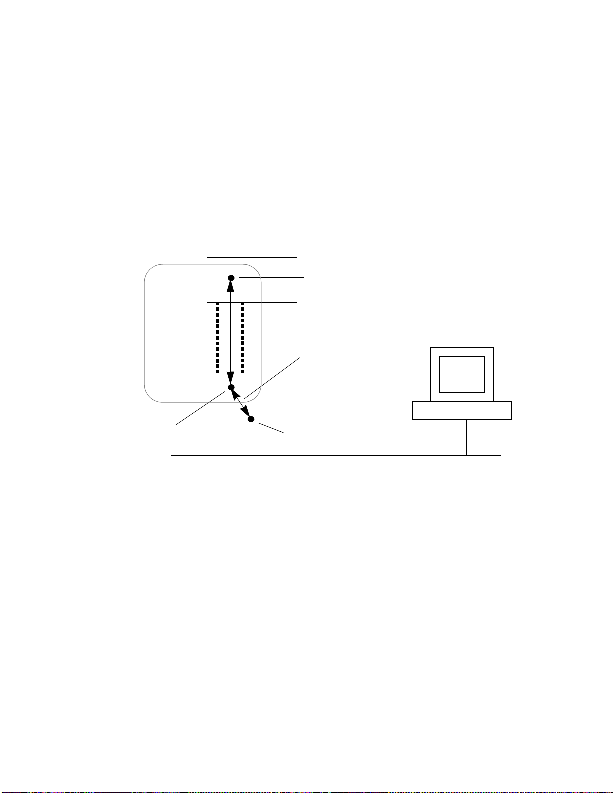
Switch Administration Lo
g
g
To see the route, enter the show route command on SW2
SmartCell ZX # show route
ROUTE NET TABLE
destination gateway flags Refcnt Use Interface
------------------------------------------------------------------------
0.0.0.0 0.0.0.0 1 0 0 zn0
90.1.1.0 90.1.1.33 1 0 1688 zn1
128.205.99.0 90.1.1.254 1 3 5660 zn1
------------------------------------------------------------------------
ROUTE HOST TABLE
destination gateway flags Refcnt Use Interface
------------------------------------------------------------------------
127.0.0.1 127.0.0.1 5 0 0 lo0
------------------------------------------------------------------------
SmartCell ZX #
Switch client
SW2
on SW2, 90.1.1.33
s and Alarms
ELAN
IP Route
IISP Route
Switch client on SW1 is
defined as SW2’s
ateway to the Ethernet
NMS
SW1
Switch client
on SW1,
90.1.1.254
Ethernet interface
128.205.99.254
Ethernet network 128.205.99.0
Figure 4-3 IP routing through SW1 for connectivity to the Ethernet network
4.4 LOGS AND ALARMS
This section discusses the log and alarm features, concepts, and the commands provided by the SmartCell 6A000
switch for setting and using the log and alarm options.
SmartCell 6A000 User Guide 4-11
Page 46

Lo
g
s and Alarms Switch Administration
4.4.1 Log Message System
The software modules and submodules of the SmartCell 6A000 switch automatically generate log messages. These
messages are stored in the log message b uffer , residing in system memory. Messages are conditionally forwarded from
the log message buffer to two other buffers: the log trace buffer and the alarm message buffer. You can view log
messages directly from the log message buffer. However, you can filter and prioritize messages by viewing them
through the log trace and alarm message buffers.
How Log Messages and Alarm Messages Differ
Alarms are log messages that are forwarded from the log message buffer into the alarm messa ge buffer. Forwarding is
based on user-defined filters of the error flags contained within the log messages. Use the
modify logalarmmask commands to view and modify the Alarm Message flag settings.
The alarm message buffer resides in flash RAM and is non-volatile. For example, if a switch crashes and is then
rebooted, you can view the alarm messages that were sent just before the crash. Conversely, the contents of the log
message buffer (residing in system memory) are lost when a crash occurs.
show logalarmmask and
Use the
and to specify the size of each alarm message file within the buffer. Also, use the
modify alarmconf command to control the amount of flash memory allocated to the alarm message buffer,
modify alarmconf command to
control the number of alarm messages each file contains.
Viewing and Filtering Messages
View console system messages from one of three locations (see Figure 4-4).
• The log message buffer: A straight dump to the console of all messages in the log message buffer.
You cannot filter between the log message buffer and the console. You can turn the display of log
messages on or off using the
modify logprint command.
• The log trace buffer: All log messages are forwarded into the log tr ace buffer from the log message
buffer. To filter messages sent to the console use the
filtering occurs between the log trace buffer and the console, affecting only the display . You can turn
log trace messages on and off by changing the setting of
command.
modify logtrace command. Notice that
quietmode from the modify logtrace
• The alarm message buffer: To view alarm messages, enter the show alarm command. To show a
single alarm, specify the alarm buffer index number. Accepting the default index of
alarm messages in the mlarm message buffer.
Notice that filtering on alarm messages occurs between the log message buffer and alarm message buffers, not between
the alarm message buffer and the console.
all displays all
4-12 SmartCell 6A000 User Guide
Page 47
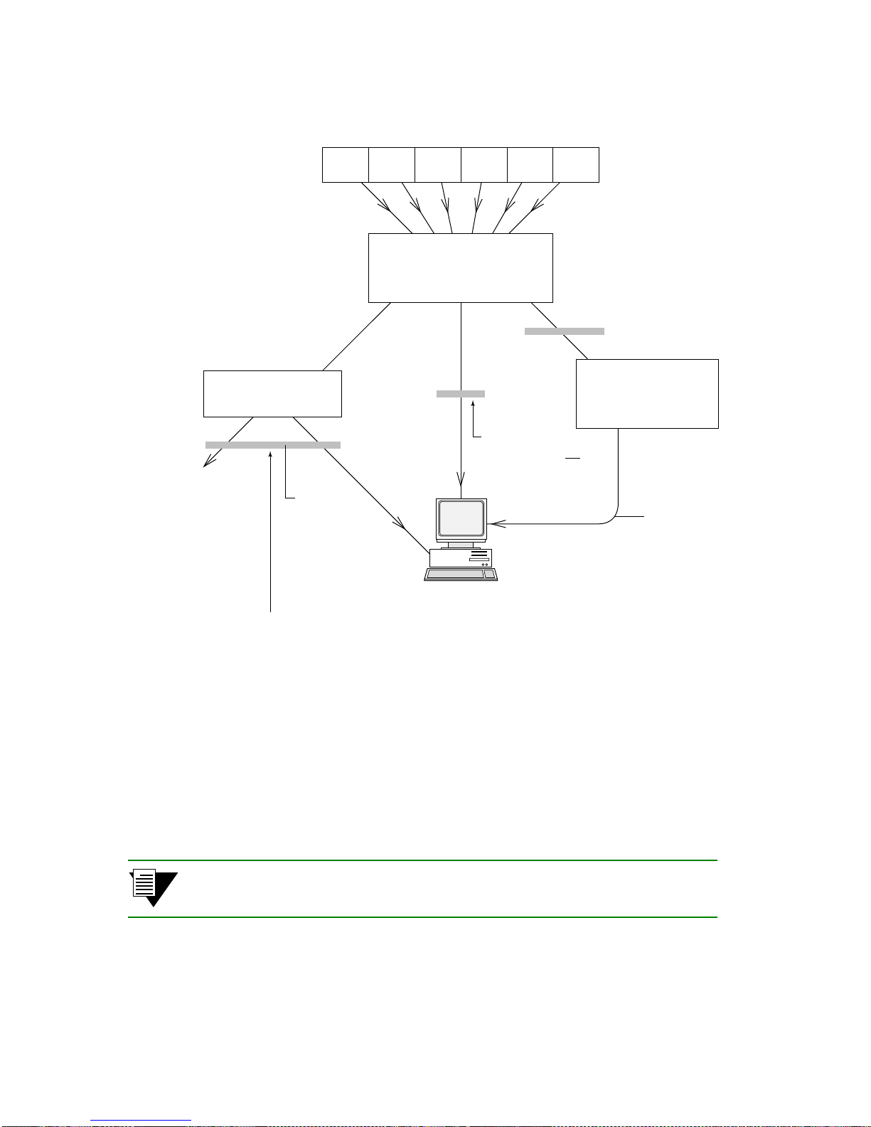
Switch Administration Settin
g
Modules & Submodules (SW)
Log Buffer
(Sys Mem)
Filter on
Set Log Alarm Mask
Up PVC Connections
Log T r ace
Buffer
No Filtering
Remote
Clients
One parameter of set LogTrace is Quiet Mode,
which controls whether any Log Messages
are printed, reguardless of filtering.
Filter on
Set Log Trace
Console
On / Off
Displays Logs
if set LogPrint is On
Alarm Message
Buffer
(Flash Mem)
Displayed by
Show Alarm
command
Figure 4-4 How log and alarm messages are accessed and displayed
4.5 SETTING UP PVC CONNECTIONS
The SmartCell 6A000 supports permanent virtual circuits (PVC s), both point-to-point and point-to-multipoint. Use
PVCs to connect devices that do not support SVCs to a switch's local client or through the switch to form a PVC link
with other devices.
Note The SmartCell 6A000 supports PVCs for IP over ATM only.
Use point-to-point PVCs to connect one end node to another for two-way communication. Use point-to-multipoint
PVCs to connect a broadcast end node to a group of receiving end nodes; traffic is one-way.
SmartCell 6A000 User Guide 4-13
Page 48

Settin
g
Up PVC Connections Switch Administration
4.5.1 Point-to-Point PVCs
The procedure for setting up a PVC between two end nodes through the SmartCell 6A000 consists of specifying the
ports and the virtual path and virtual channel identifiers (VPI and VCI).
1. Use add pvc to create the PVC; specify the ports through which the connection is established and
the VPI/VCI pair to use with each port.
SmartCell ZX # add pvc
ConnType(PTP) :
LowPort(A1) : c1
LowVPI(0) :
LowVCI(33) : 100
HighPort(A1) : b2
HighVPI(0) :
HighVCI(34) : 100
FwdTrafficDescriptorIndex(1) :
BkwTrafficDescriptorIndex(1) :
SmartCell ZX #
The example above creates a PVC between ports C1 and B2 with VPI/VCI = 0/100.
2. Plug the end nodes into the specified SmartCell 6A000 ports (C1 and B2).
3. Configure each end node with the proper IP address, subnet mask, and VPI/VCI pair = 0/100.
The end nodes can communicate with each other through the point-to-point PVC connection.
<specify port C1
<accept the default VPI, 0
<use 100 for VCI
<specify port B2
Connecting to Local Client Through Point-to-Point PVC
All PVC connections to SmartCell 6A000 local clients use B4 (the CPU port) as the HighPort.
Follow these instructions to connect an end n ode to a SmartCell 6A000 local client through a point-to-point PVC.
1. Use add pvc to create the PVC.
SmartCell ZX # add pvc
ConnType(PTP) :
LowPort(A1) :
LowVPI(0) :
LowVCI(33) : 100
HighPort(A1) : b4
HighVPI(0) :
HighVCI(34) : 100
FwdTrafficDescriptorIndex(1) :
BkwTrafficDescriptorIndex(1) :
SmartCell ZX #
2. Use add ipatmclient to create the IP over ATM local client.
SmartCell ZX # add ipatmclient
ClientNumber(0) : 2
ServerType(NONE) :
ServerAddress() :
IPAddress() : 10.1.1.0
NetMask(255.0.0.0) :
MTU(9180) :
SmartCell ZX #
<use a point-to-poin t PVC
<use port A1 in this exampl e
<HighPort must be B4
<use client # 2 in this exam ple
<accept defau lt
4-14 SmartCell 6A000 User Guide
Page 49

Switch Administration Settin
g
Up PVC Connections
3. Use add ipatmpvc to associate the end node's IP address with the PVC.
SmartCell ZX # add ipatmpvc
ClientNumber(0) : 2
DestinationIP() : 10.1.1.22
DestinationVPI(0) :
DestinationVCI(33) : 100
SmartCell ZX #
<specify local client number
<end node's IP address
<VCI was specified as 100
4. Connect the end node to port A1 of the SmartCell 6A000.
5. Configure the end node with IP address 10.1.1.2 2, subnet mask 255.0 .0.0, and VPI/VCI pair = 0/100.
4.5.2 Point-to-Multipoint PVCs
Instructions in this section describe how to set up a point-to-multipoint connection through your SmartCell 6A000.
Example: Create a point-to-multipoint connection between a broadcasting workstation on port A1 and three other
workstations connected to ports B2, B3, and C1.
1. Use add trafficdescriptor to create a backward traffic descriptor with AAL Type = null. This
assures that traffic on the PVC is one way only.
SmartCell ZX # add trafficdescriptor
TrafficType(UBR) :
TrafficDescriptorType(8) :
PCRCLP01(0) :
PCRCLP0(0) :
SCRCLP01(0) :
SCRCLP0(0) :
MBSCLP01(0) :
MBSCLP0(0) :
QOSClass(1) :
AALType(5) : 0
SmartCell ZX #
2. Use show trafficdescriptor to obtain the new traffic descriptor index number.
SmartCell ZX # show trafficdescriptor
TD# Traff Desc QoS Peak Cell Rate Sust Cell Rate Max Burst Size Aal VC
Type Type (Kb/s) (Kb/s) (Kb) Type Type
CLP_0 CLP_0+1 CLP_0 CLP_0+1 CLP_0 CLP_0+1
============================================================================
1 UBR 8 4 0 34 0 0 0 0 5 PVC
2 NRTVBR 2 1 0 1372 0 0 0 0 5 PVC
3 UBR 8 1 0 0 0 0 0 0 5 PVC
4 UBR 8 1 0 0 0 0 0 0 0 PVC
4155 UBR 8 0 0 138889 0 0 0 0 5 SVC
4158 UBR 8 0 0 353 0 0 0 0 5 SVC
4162 UBR 8 0 0 353 0 0 0 0 5 SVC
4180 UBR 8 0 0 353 0 0 0 0 5 SVC
SmartCell ZX #
<set AAL Type = null.
In the example above, traffic descriptor # 4 (left column) has AALType 0 (null).
SmartCell 6A000 User Guide 4-15
Page 50
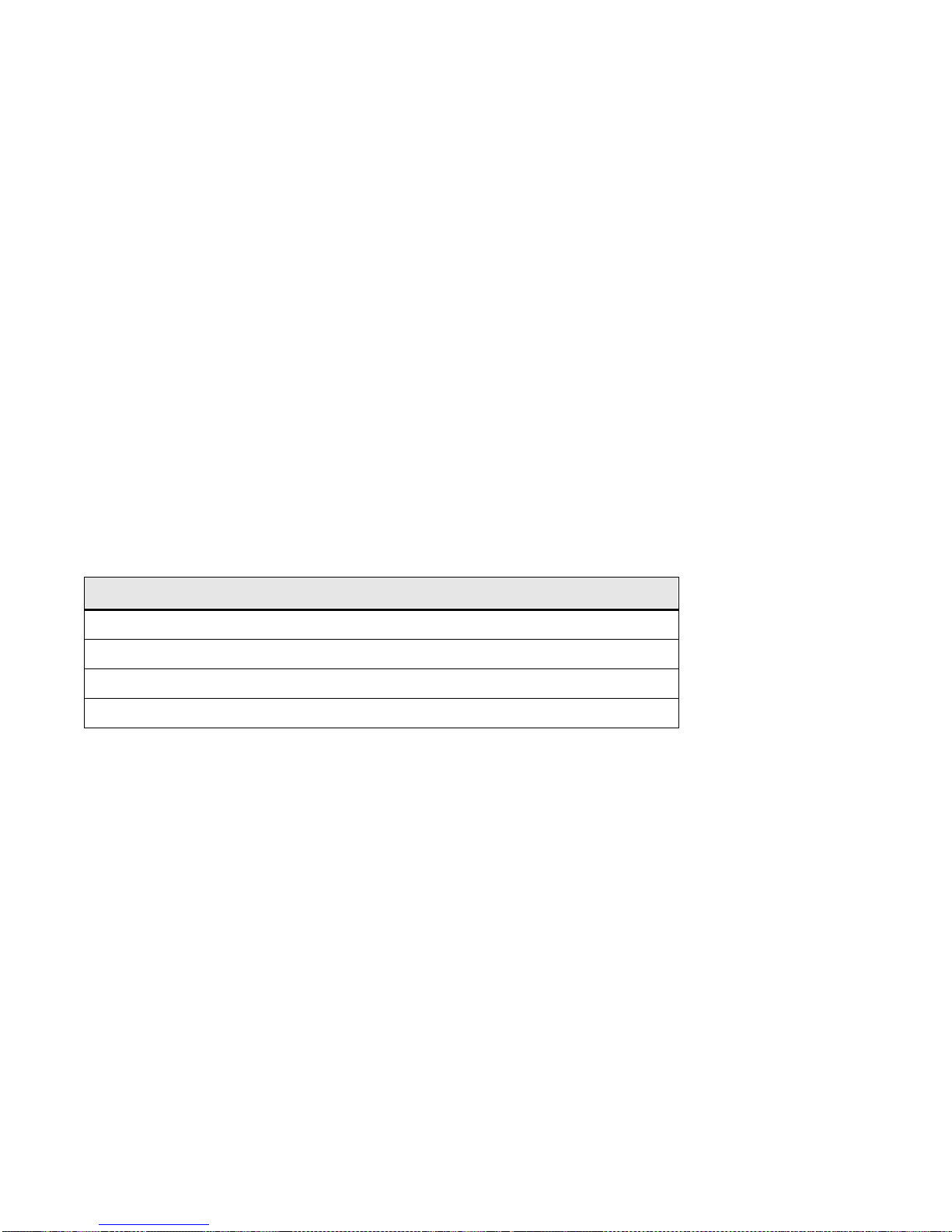
Settin
g
Up PVC Connections Switch Administration
3. Use add pvc to successively create point-to-multipoint PVCs for ports B2, B3, and C1.
SmartCell ZX # add pvc
ConnType(PTP) : pmp
LowPort(A1) :
LowVPI(0) :
LowVCI(33) : 100
HighPort(A1) : b2
HighVPI(0) :
HighVCI(34) : 100
FwdTrafficDescriptorIndex(1) :
BkwTrafficDescriptorIndex(1) : 4
SmartCell ZX #
Perform step 3 for ports B3 and C1.
<specify point-to-mul tipoint
<port connected to broadcast workstation
<port connected to first receiver workstation
<Index of Traffic Descriptor with AALType = 0
4. Connect the workstations to their respective ports.
5. Configure the workstations with the same subnet and VPI/VCI pair.
The broadcasting workstation on port A1 can send traffic to the receiving workstations on ports B2, B3, and C1.
4.5.3 Non- zer o VPIs
The SmartCell 6A000 uses 12 bits to define VPI/VCI pairs. vccmask determines how many of the 12 bits are used for
the VPI and how many are used for the VCI.
combinations. Table 4-1 shows the registers and the values that come preconfigured on the SmartCell 6A000.
Table 4-1 Values for VPI and VCI
vccmask uses a 2-bit register to hold four different VPI/VCI 12-bit
VCC Index VPI Bits VPI Values VCI Bits VCI Values
000120 to 4095
1 2 0 to 3 10 0 to 1023
2 4 0 to 15 8 0 to 255
3 6 0 to 63 6 0 to 63
Use the
SmartCell ZX # show vccmask
MaskIndex VpiShift VciShift
(In bits) (In bits)
============================================================================
0 0 12
1 2 10
2 4 8
3 6 6
SmartCell ZX #
show vccmask command to view the four preconfigured VPI/VCI combinations.
VCCMask combinations dictate what numerical values can be used for VPI/VCI pairs. Any VPI and VCI pairs that fit
the bit distributi on o f on e of t h e in dexed combinations can be used fo r defining a PVC. If the VPI and VCI v a lues d o
not fit one of the indexed combination s, th e SmartC ell 6A000 uses the closest matching indexed combination.
If you need to use values for VPI and VCI that do not fall within the range of one of the preconfigured indexed
combinations, use the
set vccmask command to replace one of the preconfigured combinations.
4-16 SmartCell 6A000 User Guide
Page 51

Switch Administration Settin
g
Up PVC Connections
For example, change VCCMask indexed combination zero (0) from VPI = 0 bits and VCI = 12 bits to
VPI = 3 bits and VCI = 9 bits.
1. Use set vccmask to change the VPI/VCI values to 3/9.
SmartCell ZX # set vccmask
MaskIndex(0) :
VPIShift(0) : 3
VCIShift(12) : 9
SmartCell ZX #
<replace the fi rs t V P I/VCI pair
2. Use the show vccmask command to see the new VPI/VCI combination.
SmartCell ZX # show vccmask
MaskIndex VpiShift VciShift
(In bits) (In bits)
============================================================================
0 3 9
1 2 10
2 4 8
3 6 6
SmartCell ZX #
<for index 0, VPI/VCI now equals 3/9
3. Use the set portconfig command to reconfigure a port to use the new values for VPI and VCI. For
example, to set up a PVC on port A1 using the new VPI/VCI bit ranges (3/9), enter
SmartCell ZX # set portconfig a1
MaxVPIBits(0) : 3
MaxVCIBits(12) : 9
InterfaceAddressType(PRIVATE) :
Trying to change VPI/VCI bits. This might affect existing PVCs.
Proceed any way?
Confirm(y/n)?:y
SmartCell ZX #
4. Use show portconfig to see the change to port A1.
SmartCell ZX # show portconfig a1
Port A1 Configuration
============================================================================
Port Id : A1
Port Admin State : ACTIVE
Port QSAAL State : UP
Port Operational State : UP
Transmission Type : STS-3c
Media Type : MMF
Address Type : PRIVATE
Active VPI Bits : 2
Active VCI Bits : 10
Configured VPI Bits : 3
Configured VCI Bits : 9
Current VPI Bits : 2
Current VCI Bits : 10
Current In Use VCCs : 3
Current Max VCCs : 4096
SmartCell ZX #
<VPI on port A1 can now be any 3-b it number
<VCI on port A1 can now be any 9-bit numb er
PVCs can be configured for port A1 using VPI values from 0 to 7 and VCI values from 0 to 511.
Note Do not set the VCI part of the VCCMask to fewer than 5 bits.
SmartCell 6A000 User Guide 4-17
Page 52

Traffic Mana
g
ement Switch Administration
Note Do not change the VCC Mask for the CPU port (B4).
4.6 TRAFFIC MANAGEMENT
This section describes how t he SmartCell 6A000 ATM switch manages bandwidth and congestion. It briefl y describes
console commands that affect how the switch manages traffic. This section also provides guidelines for setting some
traffic control parameters.
For information on troubleshooting congestion problems, see Chapter 5, "Troubleshooting."
The SmartCell 6A000 has extensive abilities for managing the flow of traffic. Traffic management includes all
operations that insure optimum switch throughput, where throughput is based on rate of packet loss, available
bandwidth, and traffic processing overhead. Under most conditions , the switch can efficiently and automatically
manage traffic. However , if necessary , you can adjust the switch traffic managemen t parameters. For example, it might
be necessary to adjust parameters for a port that carries a large amount of CBR traffic or a very large number of
simultaneous connection s.
The SmartCell 6A000 console commands affect traffic flow on a per-QoS, per-port, and global basis. These console
commands affect switch traffic flow by controlling
• Bandwidth allocation
• Call Admission Control (CAC) policies
• Class of service for a connection
• Buffer memory allocation
• Threshold settings for anti-congestion routines
Caution Do not change traffic control settings unless you have expert-level experience
with ATM switching. Back up the switch configuration before making changes.
Also, make notes of the changes you make to the traffic control parameters.
4.6.1 Traffic Descriptors
Traffic characteristics of an ATM source are signaled through a set of traffic descriptors during connection
establishment. The SmartCell 6A000 uses traffic descriptors for resource allocation during call set up, and guarantees
the QoS across the connection. The source traffic descriptor is a set of parameters that describes the expected
bandwidth utilization of a connection. You can set these parameters, which include
• Peak cell rate (PCR)
• Sustainable cell rate (SCR) and maximum burst size (MBS)
• Min imum cell rate (MC R) an d initial cell rate (ICR) — through UNI4.0 signaling only
Traffic descriptors vary for each QoS. If a connection is bi-directional, a traffic descriptor has to be assigned to each
direction and need not be the same in both directions.
4-18 SmartCell 6A000 User Guide
Page 53

Switch Administration Traffic Mana
g
ement
SmartCell 6A000 user data cells are classified according to the state of a cell loss priority (CLP) bit in the header of
each cell. A CLP 1 cell has a lower priority than a CLP 0 cell, and is discarded first. Source traffic descriptors can
specify CLP 0 cell traffic, CLP 1 cell traffic, or the aggregate CLP 0+1 traffic.
Use the
For example, enter the
SmartCell ZX# show trafficdescriptor
TD# Traff Desc QoS Peak Cell Rate Sust Cell Rate Max Burst Size Aal VC
Type Type (Kb/s) (Kb/s) (Kb) Type Type
CLP_0 CLP_0+1 CLP_0 CLP_0+1 CLP_0 CLP_0+1
============================================================================
1 UBR 8 4 0 34 0 0 0 0 5 PVC
2 NRTVBR 2 1 0 1372 0 0 0 0 5 PVC
3 CBR 3 1 500 1000 0 0 0 0 3 PVC
4162 UBR 8 0 0 138889 0 0 0 0 5 SVC
7632 UBR 8 0 0 138889 0 0 0 0 5 SVC
7661 UBR 8 0 0 138889 0 0 0 0 5 SVC
7983 UBR 8 0 0 138889 0 0 0 0 5 SVC
8046 UBR 8 0 0 138889 0 0 0 0 5 SVC
11642 UBR 8 0 0 138889 0 0 0 0 5 SVC
SmartCell ZX#
trafficdescriptor commands to view, create, and delete traffic descriptors.
show trafficdescriptor command to view all currently defined traffic descriptors.
The Descriptor Type parameter in the example above corresponds to the traffic descriptor types defined in the
UNI3.0/UNI3.1specification. Descriptor types are specified numerically and are as follows:
1 = No Traffic Descriptor
2 = Traffic Descriptor with no CLP and no SCR
3 = Traffic Descriptor with CLP, no Tagging, and no SCR
4 = Traffic Descriptor with CLP, Tagging, and no SCR
5 = Traffic Descriptor with no CLP and SCR
6 = Traffic Descriptor with CLP, no Tagging, and SCR
7 = Traffic Descriptor with CLP, Tagging, and SCR
8 = Traffic Descriptor with CLP and best effort
PVCs can use user-defined traffic descriptors. For instance, if a video link over a PVC requires a constant data flow of
5000 kb/s and a peak cell rate of 8000 kb/s, create a traffic descriptor for CBR traffic that specifies 5000 as the
sustained cell rate and 8000 as the peak cell rate.
SmartCell ZX # add trafficdescriptor
TrafficType(UBR) : CBR
TrafficDescriptorType(8) : 3
PCRCLP01(0) : 8000
PCRCLP0(0) :
SCRCLP01(0) : 5000
SCRCLP0(0) :
MBSCLP01(0) : 10000
MBSCLP0(0) :
QOSClass(1) :
AALType(5) :
SmartCell ZX #
SmartCell 6A000 User Guide 4-19
Page 54

Traffic Mana
g
ement Switch Administration
Each traffic descriptor is identified by a unique index number. Use the index number to specify which traffic descriptor
to use when setting up a PVC. For example, the
SmartCell ZX# add pvc
ConnType(PTP) :
LowPort(A1) : b1
LowVPI(0) :
LowVCI(33) :
HighPort(A1) : b2
HighVPI(0) :
HighVCI(34) :
FwdTrafficDescriptorIndex(1) : 3
BkwTrafficDescriptorIndex(1) : 2
SmartCell ZX#
add pvc command prompts you for the traffic descriptor index.
< forward traffic descriptor in dex
< backward traffic descript or i ndex
Notice in the example above that you can use different traffic descriptors for forward and backward traffic.
4.6.2 Call Admission Control Policy
Call admission control (CAC) defines the bandwidth allocation scheme (on a per-port basis) used by the SmartCell
6A000 when setting up connections. The SmartCell 6A000 offers three schemes.
• Conservative
• Moderate
• Liberal
As mentioned above, when a call is being set up, the source sig nals to request a certain amount of ban dwidth. The CAC
policy determines the amount of risk the SmartCell 6A000 is willing to take regarding the available bandwidth when
establishing the call on a port.
For instance, if the CAC policy for a port is "conservative," the SmartCell 6A000 allows calls to b e established through
this port only if available bandwidth on the port either meets or exceeds the amount requested by the source. If there
is not enough bandwidth, the port rejects the connection. The "liberal" CAC policy allows calls to be set up even if
bandwidth is insufficient to meet the source's request.The liberal C A C policy resembles a telephone company's
resource allocation scheme. The telephone system works as long as everyone doesn't try to make a call at the same
time. Liberal CAC policy assumes enough bandwidth is av ailable to service all calls provided the majority of
connections don't transmit at the same time. Using the liberal CAC policy results in some dropped and retransmitted
cells. However, it's usually adequate for the stochastic traffic that exists on most LANs. Moderate CAC policy is a
balance between conservative and liberal port bandwidth allocation— taking risks that are tempered by an evaluation
of the traffic types that constitute the connections on the port.
4-20 SmartCell 6A000 User Guide
Page 55

Switch Administration Traffic Mana
g
ement
By default, all ports on the SmartCell 6A000 are set for liberal Call Admission Control. Use the show cacparams
command to view the current CAC policies used by each port.
SmartCell ZX# show cacparams
PortNumber(ALL) :
Port# Allocation Scheme
============================================================================
A1 LIBERAL
A2 LIBERAL
A3 LIBERAL
A4 LIBERAL
B1 LIBERAL
B2 LIBERAL
B3 LIBERAL
B4(CPU) LIBERAL
C1 LIBERAL
C2 LIBERAL
C3 LIBERAL
C4 LIBERAL
D1 LIBERAL
D2 LIBERAL
D3 LIBERAL
D4 LIBERAL
SmartCell ZX#
If there are a large number of connections on a particular port, and these connections begin to slow down and show
signs of congestion, use the
SmartCell ZX # set cacparams
PortNumber(ALL) : b2
AllocScheme(LIBERAL) : conservative
SmartCell ZX #
set cacparams command to change the CAC policy to moderate or conservative.
4.6.3 Class of Service Queues
The SmartCell 6A000 performs buffering using a shared-memor y architecture. Buffer space is divided into queues for
each class of service (QoS). In turn, ports are allocated some portion of each of the QoS queues. This allocation is
controlled on a per-port basis by the
porttrafficcongestion commands.
SmartCell 6A000 User Guide 4-21
Page 56

Traffic Mana
g
ement Switch Administration
For example, enter the show porttrafficcongestion command to view current buffer utilization.
SmartCell ZX # show porttrafficcongestion
PortNumber(ALL) :
Port ID Queue 1 Queue 2 Queue 3 Queue 4
Min Max Min Max Min Max Min Max
============================================================================
A1 20 1000 20 2000 20 1000 20 16384
A2 20 1000 20 2000 20 1000 20 16384
A3 20 1000 20 2000 20 1000 20 16384
A4 20 1000 20 2000 20 1000 20 16384
B1 20 10000 20 20000 20 10000 20 16384
B2 20 1000 20 2000 20 1000 20 16384
B3 20 1000 20 2000 20 1000 20 16384
B4(CPU) 20 1000 20 2000 20 1000 20 16384
C1 20 1000 20 2000 20 1000 20 16384
C2 20 1000 20 2000 20 1000 20 16384
C3 20 1000 20 2000 20 1000 20 16384
C4 20 1000 20 2000 20 1000 20 16384
D1 20 1000 20 2000 20 1000 20 16384
D2 20 1000 20 2000 20 1000 20 16384
D3 20 1000 20 2000 20 1000 20 16384
D4 20 1000 20 2000 20 1000 20 16384
SmartCell ZX #
Min and Max are thresholds set on a per-q ueue, per-port b asis and are measured in cells (5 3 bytes). The Min threshold
is the amount of buffer space guaranteed to a call of a particular QoS on the corre sponding p ort. The Max thr eshold is
the maximum amount of buffer space that a call of a particular QoS is allowed on the corresponding port.
QoS corresponds to the queues as follows:
• Queue 1 — Constant Bit Rate (CBR)
• Queue 2 — Real Time Variable Bit Rate (rt-VBR)
• Queue 3 — Non-real time Variable Bit Rate (Nrt-VBR)
• Queue 4 — Unspecified Bit Rate (UBR)
If calls of a particular QoS typ e are being dropped on a part icular port, use the set porttrafficcongestion comm and
to raise the queue Min threshold.
For example, to change both the Min and Max amounts of buffer space used for CBR calls on port a3, enter the
following:
SmartCell ZX # set porttrafficcongestion
Port(ALL) : a3
Queue1MinimumCellCounter(20) : 1000
Queue2MinimumCellCounter(20) :
Queue3MinimumCellCounter(20) :
Queue4MinimumCellCounter(20) :
Queue1MaximumCellCounter(1000) : 10000
Queue2MaximumCellCounter(2000) :
Queue3MaximumCellCounter(1000) :
Queue4MaximumCellCounter(16384) :
SmartCell ZX #
< Min for CBR queue
< Max for CBR queue
4-22 SmartCell 6A000 User Guide
Page 57

Switch Administration Traffic Mana
g
ement
Class of Service Queue Allocation Guidelines
The following are recommended settings for the Min and Max thresholds for the class of service queues under specific
sustained traffic conditions. Use these settings as guidelines for threshold settings:
• CBR — fewer than 100 connections on a port: Min = 50, Max = 1000
• CBR — more than 100 connections on a port: Min = 100, Max = 1000
• rt -VB R — bandwidth utilization less than 20 %: Min = 10, Max = 1000*
• rt -VB R — bandwidth utilization more than 20 %: Min = 100, Max = 4000*
• Nrt-VBR — for port B4 (CPU): Min = 100, Max = 4000
• Nrt-VBR — for all other ports: Min = 10, Max = 1000
• UBR — Min = 32, Max = 16,000
* Use the show cacstats command to view bandwidth utilization.
4.6.4 EFCI, EPD, and RM Thresholds
To control switch congestion, the SmartCell 6A000 implements standard resource management cell (RM-cell)
marking, explicit forward congestion indicator cell marking (with backward RM cell marking), and early packet
discard (EPD). These congestion control schemes are triggered when the number of cells within shared memory
reaches user definable thresholds. Use the
switchtrafficcongestion command to view and set these thresholds.
For example, enter the
SmartCell ZX # show switchtrafficcongestion
Switch Traffic Congestion Parameters
============================================================================
Queue 1 EFCI Threshold : 4096 cells
Queue 2 EFCI Threshold : 4096 cells
Queue 3 EFCI Threshold : 4096 cells
Queue 4 EFCI Threshold : 4096 cells
Low EPD Threshold : 10922 cells
High EPD Threshold : 21845 cells
Switch Discard Threshold : 30508 cells
RM Cell Marking Enable : ON
EFCI Cell Marking Enable : ON
SmartCell ZX #
show switchtrafficcongestion command.
EFCI thresholds are set on a per class of service queue basis, while EPD thresholds are set with respect to the total
amount of shared buffer space being used by all classes of service.
For most types of traffic, EPD triggering is tied to the low EPD threshold. Signaling traffic, however, is tied to the high
EPD threshold to assure that signaling packets are discarded only when congestion is most severe.
Use the
set switchtrafficcongestion command to change thresholds for EFCI and EPD and to enable or disable
RM and EFCI cell marking.
Along with EFCI and backward RM cell marking, the SmartCell 6A000 uses standard RM cell marking. The switch
discard threshold (
show switchtrafficcongestion) corresponds to total shared buffer utilization and represents the
point at which the switch considers itself congested and starts marking RM cells.
The switch discard threshold is not user configurable and is shown only for information.
For information on troubleshooting congestion problems, see Chapter 5, "Troubleshooting."
SmartCell 6A000 User Guide 4-23
Page 58

Traffic Mana
g
ement Switch Administration
4-24 SmartCell 6A000 User Guide
Page 59
5 TROUBLESHOOTING
(
)
(
This chapter provides basic troubleshooting for diagnosing and fixing problems with VLANs, emulated LANs, and
ATM traffic congestion.
Note T o turn of f most of the error message display on the console screen, enter the set
logprint off command.
5.1 TROUBLESHOOTING IP OVER ATM
If you have configured an IP over ATM VLAN, but your network applications are not working. Use these questions
and tests to help determine the cause of the problem.
1.
Check for connectivity: Try pinging between end nodes and from the SmartCell 6A000
start ping
using
disconnected cable, and so on).
2. Check IP routes and addresses.
• Use the show route command to check the SmartCell 6A000 route table.
- Are the destination addresses correct for the specified gateways?
- Are there any routing loops?
- Are one or more of the destination addresses mapped to the wrong subnet?
to its end nodes. If you cannot ping, check physical connectivity
• Use show client (ARP server is on SmartCell 6A000) to check the local client.
- Does the client have the correct IP address?
- Is the subnet correct? Is the ATM address correct?
- Is the server type correct?
• Check end node configurations.
- Are end nodes configured correctly?
3. Check ARP statistics.
• Use show ipatmarp (if the ARP server is on the SmartCell 6A000).
- Are there entries in the table?
- Are the ATM addresses correct?
• Use show clientarp (if the ARP server is not on the SmartCell 6A000) to check local client's ARP
Table.
- Are there entries in the table? If not, recheck client and end node configuration.
- Are the ATM addresses correct?
SmartCell 6A000 User Guide 5-1
Page 60

Troubleshootin
g
g
(
)
(
4. Check ILMI, UNI routes, and PVCs (if applicable).
LAN Emulation Troubleshootin
• If using SVCs, use show uniroute to check whether static UNI routes are correct and whether
dynamic UNI routes are established and correct. If dynamic routes are incorrect or missing, try
creating static routes instead.
• If using PVCs, use show pvc to check whether PVCs connect the correct resources through the
correct ports.
• If using PVCs, use show ipatmpvc to check whether local switch clients are mapped to the correct
end node IP addresses.
5. If working through these questions does not solve the problem, contact Cabletron Systems Customer
Service. (See Appendix C, "Technical Support." )
5.2 TROUBLESHOOTING LAN EMULATION
You have configured an Emulated LAN and your network appli cations ar e not wo rking. Us e these quest ions an d tests
to help determine the cause of the problem.
1.
Check for connectivity. Try pinging between end nodes. Ping from the SmartCell 6A000
start ping
using
disconnected cable, and so on).
2. Check IP routes and addresses.
• Use the show route command to check the SmartCell 6A000 route table.
- Are the destination addresses correct for the specified gateways?
- Are there any routing loops?
- Are one or more of the destination addresses mapped to the wrong subnet?
to its end nodes. If you cannot ping, check physical connectivity
• Use show client to check the SmartCell 6A000 local ELAN client.
- — Does the client have the correct IP address?
- — Is the subnet correct?
- — Is the ATM address correct?
- — Is the server type correct?
• Check end node configurations.
- Are end nodes configured correctly?
3. If the ELAN spans multiple switches, check the following:
• Is the LECS address correct on all switches?
• Can all switches reach the switch providing LECS support?
• If using the Well Known LECS Address, are all switches correctly mapped?
4. Check the LECS database.
• Use show lecselan to check the names and numbers of ELANs.
- Are ELAN names correct?
- Is the ATM address of the LES correct?
5-2 SmartCell 6A000 User Guide
Page 61

Troubleshootin
g
5. Check whether BUS is connected.
Troubleshooting Congestion
• Use show busclient to check whether devices are registered with the BUS. If clients are registered,
check end node configuration. If not registered, check MP signaling.
• Use set leselan to turn off MP signaling on a per-ELAN basis.
- Do devices begin to register with the LES and BUS once MP signaling is turned off?
• Check IISP routes to the switch containing the LES and BUS.
- Are all IISP routes correct?
- Does a new IISP route need to be added so devices can reach the LES and BUS?
6. If working through these questions do es not solve the problem, contact Cablet ron Systems Customer
Service. (See Appendix C, "Technical Support." )
5.3 TROUBLESHOOTING CONGESTION
If the bandwidth of your SmartCell 6A000 begins to decrease, and if connections are being lost or packets are being
dropped at a high rate, it's possible that your switch is becoming congested. Congestion can occur on the port level,
the global switch level, or both levels.
If you suspect that your SmartCell 6A000 switch is congested, follow the steps outlined belo w to diagnose and resolve
the cause of congestion.
5.3.1 Diagnosing Congestion
1.
Enter the
2. If cells are not being dropped on all ports, proceed to the "Port Congestion" section.
3. If cells are being dropped on all ports, the indication is global congestion. Proceed to the "Global
Congestion" section.
show portstats
command, and take the default of
all
.
5.3.2 Global Congestion
1.
Is the total cell drop rate equal to the Unknown VC cell drop rate?
• If ye s, the switch is improperly set up. Check the switch configuration.
• If no, this indicates global congestion. Continue.
2. Set the porttrafficcongestion values to those recommended in the "Class of Service Queue
Allocation Guidelines" section. Has the congestion subsided?
• If yes, you are done.
• If no, continue.
3. Have you changed the EPD threshold?
• If yes, replace it to the default setting. If congestion subsides, you are done.
• If no, continue.
SmartCell 6A000 User Guide 5-3
Page 62

Troubleshootin
g
g
q
4. Enter the show cacstats command for each port. Is the allocated b andwidth small and is the traf fic
Congestion Troubleshootin
mostly UBR?
• If no, go back to step 4 and check next port.
• If yes, continue.
5. Enter the show porttrafficcongestion command. Is the UBR queue Max threshold large?
• If no, go back to step 4.
• If yes, continue.
6. Reduce the UBR queue Max threshold by a small amount, then wait a few minutes.
7. Enter the show portstats command, and take the default of all. Is the number of cells dropped
increasing for this port, and quickly decreasing for all other ports?
• If yes, proceed to the "Port Congestion" section.
• If no, continue.
8. Is the number of cells being dropped by all other ports decreasing somewhat?
• If no, go back to step 7.
• If yes, continue.
9. Enter the set cacparams command and set call admission control for this port to a more
conservative policy (
10. Go back to step 4 until all ports have been checked.
moderate or conservative).
5.3.3 Port Congestion
1.
Enter the
unknown VCs dropped. Is the difference for cells dropped e
dropped?
show portstats
command a few times, noting the value for cells dropped and
ual to the difference for VCs
• If ye s, the switch is improperly set up. Check the switch configuration.
• If no, this indicates port congestion. Continue.
2. Enter the show cacstats command for this port. Note the bandwidth allocated for each Class of
Service on this port.
3. For each class of service, enter the set porttrafficcongestion command. Set the Max threshold
to the value recommended in the "Class of Service Queue Allocation Guidelines" section.
4. Have you performed step 3 for every class of service for this port?
• If no, go to step 3.
• If yes, continue.
5. Enter the set cacparams command for this port. Set call admission control for this port to a more
conservative policy (
6. Check VC statistics for this port using either the show pvc /d or the show svc /d command,
whichever is appropriate.
7. If the port belongs to the high virtual channel link (VCL), read the forward stats. If the port belongs
to the low VCL, read the backward stats. If the port belongs to both high and low VCLs, read both
stats.
moderate or conservative).
5-4 SmartCell 6A000 User Guide
Page 63

Troubleshootin
g
8. Is the number of cells received increasing?
• If no, go to step 6.
• If yes, continue.
9. Convert Allocated Bandwidth (kb/s) to cells (48 bytes).
Bandwidth in cells = (1024 X Allocated Bandwidth) / 384
where 384 = 48 cells X 8
10. Is the Allocated Bandwidth less than the Cell Reception Rate?
• If no, go to step 6.
• If yes, this VC is misbehaving. Take appropriate action, for example, terminate the VC.
Troubleshooting Congestion
SmartCell 6A000 User Guide 5-5
Page 64

Troubleshootin
g
g
Congestion Troubleshootin
5-6 SmartCell 6A000 User Guide
Page 65
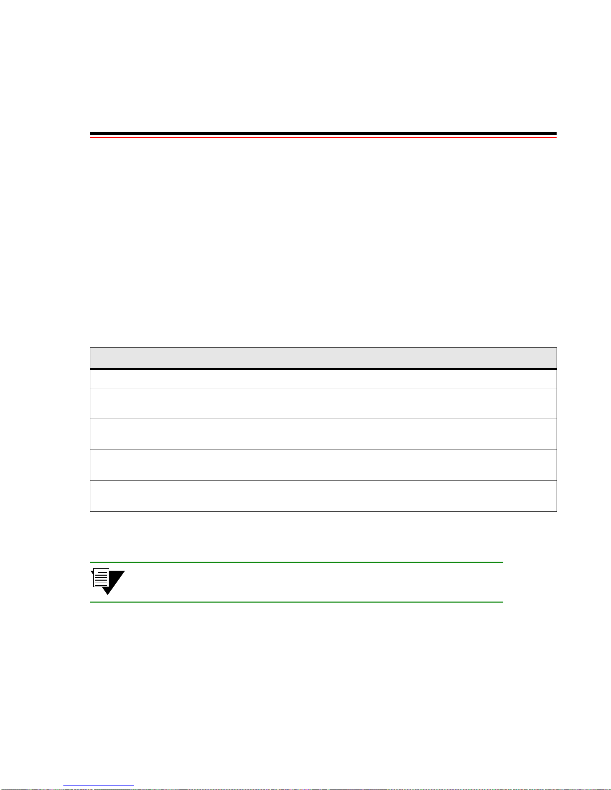
APPENDIX A FEATURES AND
SPECIFICATIONS
This appendix describes SmartCell 6A000 switch h ardware information, pro duct features, technical speci fications, and
adapter pin-out descriptions.
A.1 HARDWARE COMPONENTS
This section describes the hardware components of the SmartCell 6A000 ATM switch.
A.1.1 Front Panel
Table A-1 tells how to read the LEDs on the front panel.
Table A-1 Front panel LEDs
LED Function
FAIL (red) Normally OFF; ON indicates CPU failed.
STATUS
(amber)
POWER
(green)
RX DATA
(green)
TX DATA
(green)
Figure A-1 illustrates the front panel of the SmartCell 6A000 switch.
Normally OFF; ON indicates an error condition that prevents alarm information from being
displayed to the console.
Normally ON; OFF indicates the CPU is receiving power from the power supply.
Normally FLASHING intermittently if there is receive activity on the port; indicates the Ethernet
port is up and receiving Ethernet frames.
Normally FLASHING intermittently if there is transmit activity on the port; indicates the Ethernet
port is up and transmitting Ethernet frames.
Note The ‘MON' and ‘DIAG' functions are not used in this release.
SmartCell 6A000 User Guide Appendix A-1
Page 66
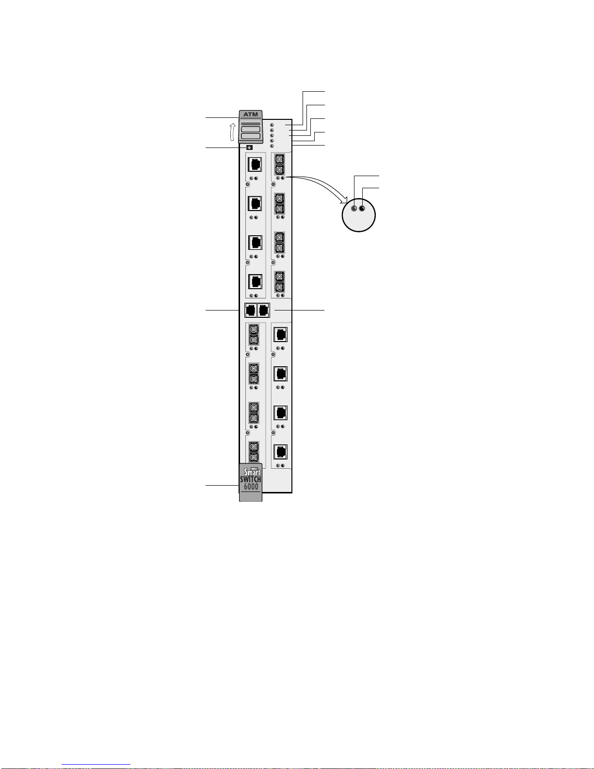
Hardware Components Features and Specifications
FAIL
STATUS
Ejector
Reset Button
FAIL
S
Y
STATUS
S
POWER
T
RX ENET
E
TX ENET
M
1234
1 2 3
NO SYNC
DATA
NO SYNC
DATA
POWER
RX DATA
TX DATA
DATA
NO SYNC
NO SYNC
DATA
Ethernet Port
(10Base-T)
Console T erminal
(RJ-45)
6A-IOM-21-4
6A-IOM-22-4
AC
4
E
T
C
O
M
H
E
R
N
E
T
123
1234
NO SYNC
DATA
NO SYNC
DATA
6A-IOM-22-4
6A-IOM-21-4
BD
4
Ejector
Figure A-1 Front panel
A.1.2 CPU Module
The CPU module provides control, signaling, and LA N server functions for the switch. A 32 -bit RISC processor
(i960CF, 33 MHz) operates all switch software options.
An on-board Segmentation and Reassembly (SAR) ASIC pro vides r apid packet pro cessing. A co mmon DRAM bank
stores both CPU data structures and SAR processing buffers. Sixteen megabytes of DRAM is standard; 64 MB is
optional.
512 KB SRAM supports up to 4096 VCs routed through the CPU module.
Appendix A-2 SmartCell 6A000 User Guide
Page 67
Features and Specifications Hardware Components
The flash RAM provides persistent storage of bootup addresses and operations, configuration data, and system
software. Four megabytes of flash RAM is standard; 8 MB is optional.
Field-upgradeable DRAM and flash memory, mounted in standard sockets, enable future software enhancements.
An Ethernet port provides conn ection to the swit ch for LAN-based swit ch management fun ctions. An RS-23 2 console
port provides connection for local configuration and maintenance functions.
A.1.3 Switch Modules (MS M and ESM)
The Main Switch Module (MSM) contains the primary cell-switching fabric. The MSM provides switching for four
4-port I/O modules; however, only two I/O modules (8 ports) are physically connected to the MSM. In addition, one
of these 8 ports (B4) is reserved for CPU functions, yielding an effective total of 7 user ports (port numbers A1-A4
and B1-B3). For configurations requiring more than 7 user ports, an additional Expansion Switch Module (ESM) must
be added, for a total of 15 user ports. Using a shared memory architectur e, the MSM utilizes fast SRAM buffering
onboard. The MSM has 32K cells.
The ESM is a switch-expans ion module that provi des switch fabric for an ad ditional 8 ports, expand ing the switch from
7 to 15 ports. It provides connections for up to two I/O modules.
Caution If an ESM is not installed, sh eet metal blanks must cover the front slot openi ng,
maintaining EMI integrity and proper airflow.
A.1.4 Input/Output (Port) Modules
The switch supports up to four I/O modules, each of which supports four 155 Mbps STS-3c/STM-1 ports, yielding a
total of 15 user ports (the 16th port is dedicated to CPU communication). The physical interfaces are compatible with
ATM Forum Physical Layer, BellCore SONET, and ITU SDH applicable specifications. Table A-2 describes the I/O
module port LEDs.
Table A-2 Input/Output Module LEDs
LED Function
NO SYNC (amber) Normally OFF; when lit, indicates a physical layer Out Of Frame (OOF) error condition is
present on the port (receive).
DATA (green) Normally FLASHING if there is receive activity on the port; indicates the port is up and
receiving cell traffic. Solid green if link is up, off if link is down.
SmartCell 6A000 User Guide Appendix A-3
Page 68
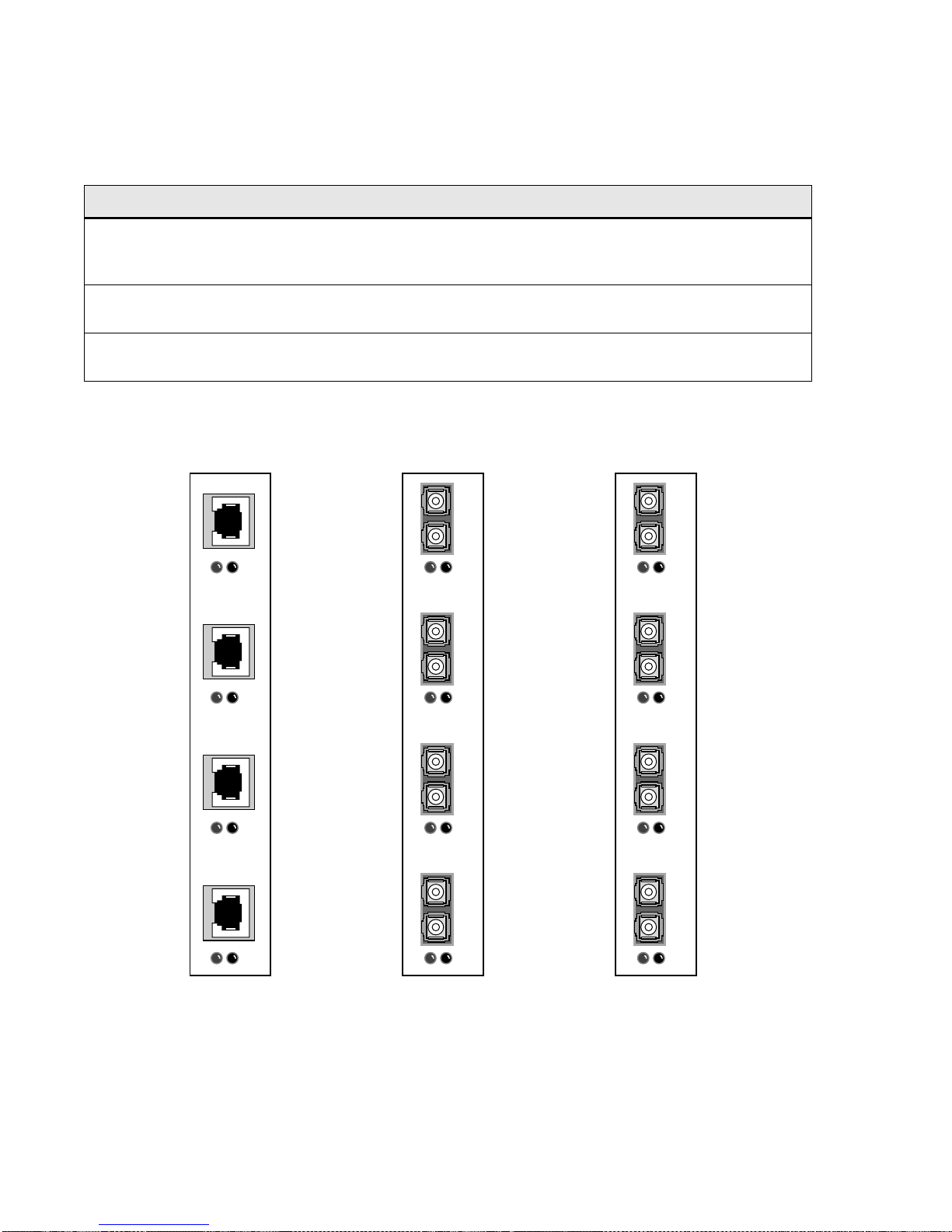
Hardware Components Features and Specifications
g
y
Three types of I/O modules are available with different physical media types, but all are based on the same basic card
design.
Table A-3 I/O port module media t
pes
Module Type Characteristics
155 Mbps STS-3c/STM-1
SMF/MMF, 4 ports
155 Mbps STS-3c/STM-1
MMF, 4 ports
155 Mbps STS-3c/STM-1
UTP5, 4 ports
NO SYNC
DATA
6A-IOM-22-4
Provides one single-mode fiber optic (SMF) and three multimode fiber optic (MMF)
user interfaces, physically connected with male SC-type fiber optic cables. The first of
the four ports is the single-mode connection.
Provides four SC-Duplex multimode fiber optic (MMF) user interfaces, physically
connected with male SC-type fiber optic cables.
Provides four Category 5 unshielded twisted pair (UTP-5) user interfaces, physically
connected with male RJ-45 cables.
SM
1234
1 2 3 4
NO SYNC
DATA
6A-IOM-21-4
1 2 3 4
NO SYNC
DATA
6A-IOM-29-4
155 Mbps STS-3c/STM-1
UTP5, 4 Ports
Fi
ure A-2 I/O modules
Appendix A-4 SmartCell 6A000 User Guide
155 Mbps STS-3c/STM-1
MMF, 4 Ports
155 Mbps STS-3c/STM-1
SMF/MMF, 4 Ports
Page 69
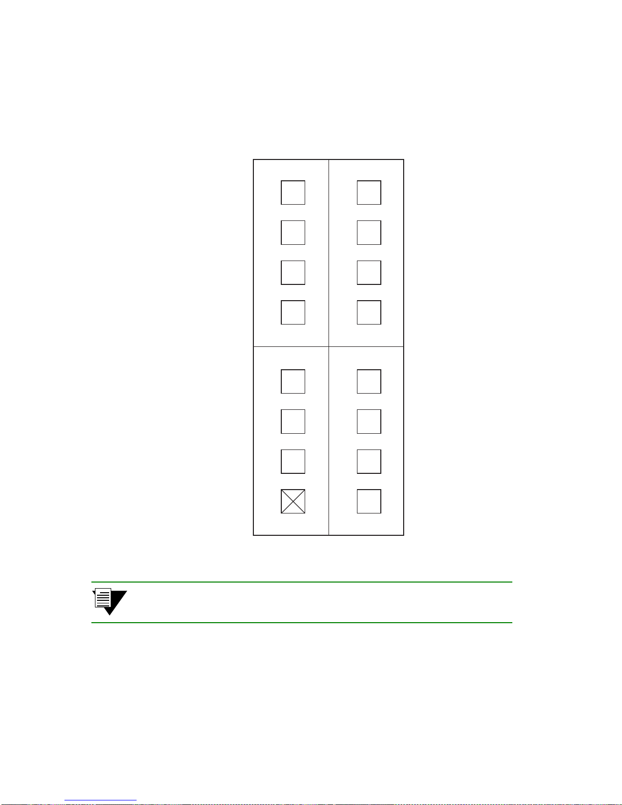
Features and Specifications Hardware Components
g
g
Port Numberin
Physical ports are always numbered from left to right (starting from 1), when viewed from the front. IOM slots are
designated A and B on the MSM and C and D on the ESM. A fully configured switch has ports numbered, as shown
in Figure A-3.
A1
A2
A3
A4
B1
B2
B3
C1
C2
C3
C4
D1
D2
D3
Fi
ure A-3 Group and port identifiers.
Note X (port B4) in Figure A-3 indicates that the port is reserved for CPU
communications.
B4
D4
SmartCell 6A000 User Guide Appendix A-5
Page 70

Features Features and Specifications
g
A.2 FEATURES
A.2.1 Switch Module
Full class-of-service support (CBR, VBR, ABR, UBR) combined with multiple priorities ensures
optimal traffic-class separation
PVC connections standard
SVC connections (with optional ZX-SW-SVC firmware image installed)
Up to 8 K point-to-point connections
Up to 4 K point-to-multipoint connections
A.2.2 CPU Module
On-board Segmentation and Reassembly (SAR) ASIC
Field-upgradeable DRAM and Flash memory mounted in SIMM sockets
Serial and Ethernet ports for local and remote management
A.2.3 I/O Modules
Up to fifteen 155 Mbps ATM ports per system
Software-selectable SONET or SDH framing
A.2.4 Signaling and Routin
UNI 3.0 or 3.1 configurable per port
ILMI auto-discovery, combined with port auto-conf iguration , ensur es plug- and-play operat ion wit h
ATM devices, including adapters and switches
IISP and PNNI Phase 0 routing
Auto-configuration of IISP and PNNI trunks in a SmartCell switch network
User-defined route weights enable customized load balancing between multiple trunk routes
A.2.5 Intelligent Call Admission Control
User selectable, per port, per traffic class call admission policies: liberal, moderate, or conservative
Appendix A-6 SmartCell 6A000 User Guide
Page 71

Features and Specifications Features
A.2.6 Connection Management
Ceiling limit protects buffer resources from being consumed by individual ports
Floor limit reserves buffer capacity for specific ports, such as those to heavily used servers or
WAN/ATM services
Four configurable thresholds for forward congestion marking (EFCI)
UNI 4.0-based backward RM cell marking for fast, closed-loop flow control for ABR connections
Multiple threshold levels for Early Packet Discard
Automatic Partial Packet Discard
A.2.7 LAN Servers and Clients
ATM Forum LAN Emulation (LANE) 1.0
Up to 127 emulated LANs (ELANs)
LANE configuration server (LECS)
LANE server (LES)
Broadcast and unknown server (BUS)
LANE client (LEC)
802.3 (Ethernet) emulation
802.5 (Token Ring) emulation
IETF RFC 1577 Classical IP over ATM
Up to 127 logical IP subnetworks (LISs)
IP-ATM (ARP) address resolution protocol server
IP-ATM client
A.2.8 Management
Serial port for terminal or modem access
Ethernet port for telnet access
In-band management using switch LANE or IP-ATM clients
Management applications: Cabletron Systems SPECTRUM for Open Systems, third-party
SNMP-based managers
SmartCell 6A000 User Guide Appendix A-7
Page 72

Specifications Features and Specifications
y
A.3 SPECIFICATIONS
A.3.1 Technical Specifications
Table A-4 Technical Specifications
Specification Value
Processor i960CF, 33 MHz
Switching engine 2.5 Gbps, non-blocking
Max I/O ports 7 for 6A000-02; 15 for 6A000-04
Switch latency 10 microseconds
CPU DRAM memory 16 MB standard; 64 MB optional
Buffer memory (cells) 32 K
flash memory 4 MB standard; 8 MB optional
Serial port RS-232c compliant; RJ-45 connector
Ethernet port IEEE 802.3 compliant; RJ-45 connector
A.3.2 Physical Specifi cations
Table A-5 Ph
Specification Value
Dimensions 41.9 cm x 6.1 cm x 28.6 cm
Product weight (with max I/O modules) 3.6 kg
Power requirements (typical) 5V, 19 amps at chassis power bus (fully
Power dissipation (typical) 1,008,000 BTU/s (95 watts) (fully loaded)
Operating temperature 15 to 40 C (41 to 104 F)
sical Specifications
16.5" x 2.4" x 11.25"
8 lbs
loaded)
Operating humidity 5% to 90% RH, non-condensing
Appendix A-8 SmartCell 6A000 User Guide
Page 73

Features and Specifications Specifications
g
g
A.3.3 ATM Port Specifications
Table A-6 ATM Port Specifications
I/O Module 6A-IOM-29-4 6A-IOM-21-4 6A-IOM-22-4
Port speed 155 Mbps 155 Mbps 155 Mbps
Framing SONET OC-3c or SDH
STM-1
SONET OC-3c or SDH
STM-1
SONET STS-3c or SDH
STM-1
Port media SMF-IR MMF Cat. 5 UTP
Port connector SC SC RJ-45
Max. power level (Tx) -Min. power l evel (Tx) -15 dBm -20 dBm -Max. power level (Rx) -8 dBm -14 dBm -Min. power l evel (Rx) -31 dBm -30 dBm -Typical reach 15 Km 2 Km 100 m
A.3.4 Standards Specifications
Table A-7 Si
Signaling and Protocols Standard
Signaling ATM Forum UNI 3.0
naling and Protocols Standards and Specifications
ATM Forum UNI 3.1
ATM Forum ILMI
Routing ATM Forum PNNI Phase 0 (IISP)
LAN protocols ATM Forum LANE 1.0 (Ethernet and Token Ring)
IETF RFC 1577 Classical IP over ATM
Table A-8 Mana
ement Standards and Specifications
Management Protocol MIBs supported
SNMPv1 MIB II (RFC 1213)
SNMPv2 Interface Table MIB (RFC 1573)
AToM MIB (RFC 1695)
SmartCell 6A000 User Guide Appendix A-9
Page 74
Specifications Features and Specifications
(
)
(
)
g
)
Table A-8 Mana
ement Standards and Specifications (Continued
Management Protocol MIBs supported
AToM2 MIB (pre-s tandard)
LANE MIB (ATM Forum)
PNNI MIB (ATM Forum)
UNI 3.0/3.1 ILMI MIB (ATM Forum)
IP over ATM MIB (pre-standard)
IISP MIB
SmartCell 6A000 Switch MIB
A.3.5 CPU Serial Port Pin-Out Descriptions
Table A-9 RJ-45 to DB -9 Adapter
RJ-45 DB-9
Pin Color Pin Description
PC Serial Port Adapter
1 Blue 2 R eceive
4Red3Transmit
5Green5Ground
Table A-10 RJ-45 to DB- 25 Adapter
Terminal Adapter
RJ-45 DB-25
Pin Color Pin Description
4Red2Transmit
1 Blue 3 R eceive
5Green7Ground
Appendix A-10 SmartCell 6A000 User Guide
Page 75
Features and Specifications Specifications
)
Table A-11 RJ-45 to DB-25 Adapter (Modem Adapter
RJ-45 DB-25
Pin Color Pin Description
1 Blue 2 Transmit
4 Red 3 Receive
5Green7Ground
SmartCell 6A000 User Guide Appendix A-11
Page 76

Specifications Features and Specifications
Appendix A-12 SmartCell 6A000 User Guide
Page 77

APPENDIX B SMARTCELL 6A000 AND
SNMP
This appendix briefly describes SNMP support and the MIB files provided (on diskette) with the SmartCell 6A000
switch.
MIB files are defined according to the following:
• MIB II (RFC 1213)
• Interface Table MIB (RFC 1573)
• AToM MIB (RFC 1695)
• AToM2 MIB (pre-standard)
• LANE MIB (ATM Forum)
• UNI 3.0/3.1 IL MI MIB (ATM Forum)
• IP over ATM MIB (pre-standard)
• IISP MIB
• SmartCell 6A000 Switch MIBs (proprietary)
Note Along with the MIBs, the diskette also contains a README file and the release
notes.
B.1 INTERNET MIB HIERARCHY
The MIB structure is logically represented by a tree hierarchy (see Figure B-1). The root of the tree is unnamed and
splits into three main branches: Consultative Committee for International Telegraph and Telephone (CCITT),
International Organization for Standardization (ISO), and joint ISO/CCITT.
These branches and those that fall below each category have short text strings and integers to identify them. Text
strings describe object names, while integers allow computer software to create compact, encoded representations of
the names. For example, the ZeitNet MIB variable znIpAtmClient is an object name (denoted by number 1,) which is
listed at the end of its object identifier number 1.3.6.1.4.1.1295.2.200.1. See the MIB listings later in this appendix for
the exact location of this object.
The object identifier in the Internet MIB hierarchy is the sequence of numeric labels on the nodes along a path from
the root to the object. The Internet standard for MIB II is represented by the object identifier 1.3.6.1.2 .1. It also can be
expressed as iso.org.dod.internet.mgmt.mib (see Figure B-1).
SmartCell 6A000 User Guide Appendix B-1
Page 78
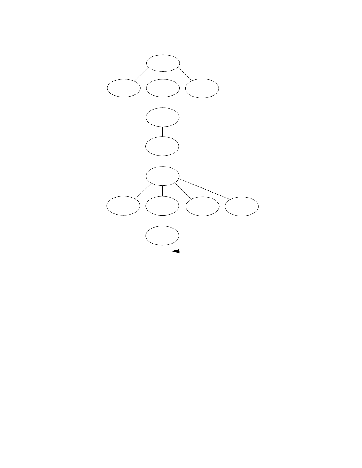
ZeitNet Proprietary MIB SmartCell 6A000 and SNMP
y
tt
root
joint
CCITT
0
ISO
1
org
3
DOD
6
internet
1
ISO/CCITT
2
directory
1
mgmt
2
MIB
1
experimental
3
Label from the root to
this point is 1.3.6.1.2.1
private
4
Figure B-1 Internet MIB Hierarch
B.2 ZEITNET PROPRIETARY MIB
The private ZeitNet MIB is represented by the object identifier 1.3.6.1.4.1.1295, or
iso.org.dod.internet.private.enterprise.zeitnet. The ZeitNet MIB includes the following subtree object identifiers:
• znManagedObjects (1295.2)
• znleMIB (1295.4)
• znIpAtmClent (1295.200.1)
• znCommon (1295.2.300)
• znLecUpAlarm (1295.2.301.4)
• znIispMIB (1295.2.3333.6)
• switchMIB (1295.200.1)
Appendix B-2 SmartCell 6A000 User Guide
Page 79
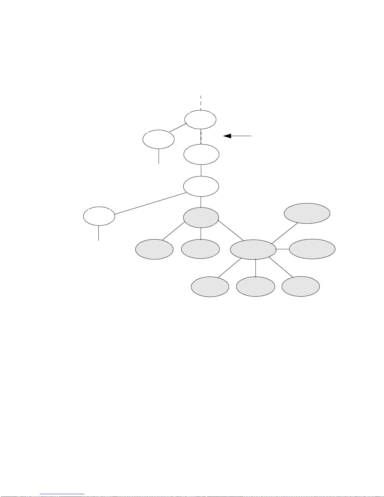
SmartCell 6A000 and SNMP ZeitNet Proprietary MIB
g
The local subtree contains MIB objects defined for Release 1.1, which implements the SNMP Structure of
Management Information (SMI). Beginning with this release, ZeitNet MIBs are defined u sing both SNMPv1 SMI and
SNMPv2. The SmartCell 6A000 MIB files also support the AToM2-MIB and those of the pre-conformance standard
of the ATM Forum, which appear on the MIB tree as in Figure B-2:
MIB
1
Label from the root to
atomMIB
37
Private
4
enterprise
1
this point is 1.3.6.1
atmForum
353
znCommonMIB
199
Fi
ure B-2 ZeitNet Private MIBs
ZeitNet
1295
znProducts
1
znCommonObjs
300
znManagedObjects
2
znTrapObjs
301
znSwitchObjedcts
3333
znAdminPolicyVal
202
znIpAtm
200
In Figure B-2, the ZeitNet proprietary group is identified by 1.3.6.1.4.1.1295; its subgroup, called znProducts, is
identified by 1; and the first variable is znManagedObjects with a value of 2. Therefore, the variable
znManagedObjects has a value of 1.3.6.1.4.1.1295.2.
B.2.1 Interpreting the Object Identifier
In this guide, each group of ZeitNet MIB variables is accompanied by an illustration that indicates the specific object
identifier for each variable.
In Figure B-3, the object identifier 1.3.6.1.4.1.1295.2.200 at the top of the illustration indicates the labeled nodes. The
last value is the number of the ZeitNet MIB variable. For example, the MIB var iable znIpAtmClientLisSubnetMask is
indicated by the number 1.1.1.3.
SmartCell 6A000 User Guide Appendix B-3
Page 80
ZeitNet Proprietary MIB SmartCell 6A000 and SNMP
g
The object identifier for hostConfigAddr is:
iso.org.dod.internet.private.enterprise.zeitnet.znProducts.znManagedObjects.znIpAtm.znIpAtmClient.znIpAtmClien
tLisTable.znIpAtmClientLisEntry.znIpAtmClientLisSubnetMask or 1.3.6.1.4.1.1295.2.200.1.1.1.3. The entire
ZeitNet Cabletron SmartCell 6A000 MIB subtree looks like Fi gure B-3.
Label from the ZeitNet root to
this point is 1.3.6.1.4.1.1295
znManagedObjects
2
znIpATM (1295.2.200)
znCommon (1295.2.300)
znTrap (1295.2.301)
znCommon (1295.2.300)
znIisp (1295.2.3333)
znLeMIB (1295.4)
Fi
ure B-3 ZeitNet Cabletron 6A000 MIB object identifier example
B.2.2 Proprietary MIB Functions
The following is a list of the ZeitNet proprietary MIBs and their general functions:
• znleMIB: SmartCell 6A000 specific VLAN related activity
• znIpAtmClentMIB: SmartCell 6A000 implementation of IP over ATM
• znCommonMIB: SmartCell 6A000 specific common objects such as enabling AutoDetect, UNI,
Signaling, Community Strings, and Traps
• znIispMIB: SmartCell 6A000 specific IISP
• switchMIB: SmartCell 6A000 specific switch ports, configuration, thresholds, queues, and timers
Note For explanations of the function of each MIB object, consult the description fields
within the respective MIB files.
Note To use the provided SmartCell 6A000 MIBs, your NMS application must be
capable of compiling both SNMPv1 and SNMPv2 MIBs.
Appendix B-4 SmartCell 6A000 User Guide
Page 81

SmartCell 6A000 and SNMP A Client for SNMP Mana
g
ement
B.3 A CLIENT FOR SNMP MANAGEMENT
Your SmartCell 6A000 must have a connection to the NMS before i t can be managed. The defa ult connection between
the SmartCell 6A000 and the NMS is the SmartCell 6A000 Ethernet interface. An NMS can also manage the SmartCell
6A000 through one of its ATM ports if the SmartCell 6A000 has a client connection into a VLAN or emulated LAN.
Note that the SmartCell 6A000 itself is not reachable through ATM until a client for the switch is created and
participates as a member of a VLAN or ELAN. Your NMS uses the switches client address to access and manage the
switch.
T o create a client for the switch, use the
for emulated LANs.
Use the
detailed information about these commands, see the SmartCell 6A000/ZX-250 Reference Manual.
set MyNmAddr command to tell the switch which interface to use when communicating with your NMS. For
add IPATMClient command for VLANs, and the add LANEClient command
B.4 CONSOLE COMMANDS THAT AFFECT THE
AGENT
The following is a list of the console commands that affect the operation of the SmartCell 6A000 SNMP agent. For
detailed descriptions of these commands, see the SmartCell 6A000 Reference Manual.
• Community: Sets the community strings for the switch
• TrapCommunity: Specifies the NMS to which traps are sent
• MyNMAddr: Sets the address of the interface through which the switch is managed
• TrustedNMS:Specifies the IP address of the NMS allowed to manage the switch
B.5 MIB EXCEPTIONS
With the current implementation of MIB files, conformance to ATM standards for the SmartCell 6A000 ATM switch
includes the following exceptions.
B.5.1 Non-Conformance
•
atmInterfaceIlmiVpi — Read-only
• atmInterfaceIlmiVci — Read-only
• atmVclLastChange — Always 0
• atm VccAalType AAL — Type will be set to 0 if a VCL is internally (not through the NMS)
• atmVccAal5EncapsType AAL — Type will be set to 0 if a VCL is internally (not through the NMS)
• atmVcCrossConnectL2HLastChange — Always 0
• atmVcCrossConnectH2LLastChange — Always 0
• aal5VccTable — Returns fake value Waiting for atom2 implementation
• atmSvcVcCrossConnectRowStatus Set — Not supported
SmartCell 6A000 User Guide Appendix B-5
Page 82

MIB Exceptions SmartCell 6A000 and SNMP
• atmConfigSigType — The values given below are not supported
-
-
-
-
-
• atmConfigSigSide — The values given below are not supported
-
-
• atmfVccQoSCategory — Always 0 as this object is deprecated
• a t mfSrvcRegPort — Always 0
• atmfSrvcRegAddressIndex — Always 1
• atmfSrvcRegServiceID — Always 1.3.6.1.4.1.353.1.5.1
• znIpAtmClientDDVcType — Accepts only pvc(2) in sets
• lecMulticastSendType — Accepts only bestEffort (1)
• lecMulticastSendAvgRate — Accepts values only up to 370370
• lecMulticastSendPeakRate — Accepts values only up to 370370
• leArpEntryType — Accepts only staticVolatile (4) and staticNonVolatile (5)
• lesControlTimeout — Read-only
B.5.2 Not Supported
The following MIB objects are not supported. If used, these objects return either the value zero or the message, "Not
supported."
• atmInterfaceMaxVpcs
• atmInterfaceConfTable
• atmInterfaceConfVpcs
• atmInterfaceConfTable
• atmInterfaceDs3PlcpTable
• atmInterfaceTCTable
• atmVplTable
• atmVpCrossConnectIndexNext
• atmVpCrossConnectTable
• atmSvcVpCrossC onnectTable
• atmSigSupportTable
• atmSigDescrParamTable
• atmIfAdminAddrTable
• atmVclAddrBindTable
• atmAddrVclTable
Appendix B-6 SmartCell 6A000 User Guide
Page 83

SmartCell 6A000 and SNMP MIB Exceptions
• atmVplStatTable
• atmVplLogicalPortTable
• atmVclGenTable
• atmfMyOsiNmNsapAddress
• atmfVpcTable
• lecRouteDescrTable
• leRDArpTable
SmartCell 6A000 User Guide Appendix B-7
Page 84

MIB Exceptions SmartCell 6A000 and SNMP
Appendix B-8 SmartCell 6A000 User Guide
Page 85

APPENDIX C TECHNICAL SUPPORT
This appendix tells you what to do if you need technical support for your SmartCell ZX-250 switch.
Cabletron off ers several support and service programs that provide high-qu ality support to our customers. For technical
support, first contact your place of purchase. If you need additional assistance, contact Cabletron Systems, Inc. There
are several easy ways to reach Cabletron Customer Support and Service.
C.1 TELEPHONE ASSISTANCE
Our Technical Support Center is available Monday through Friday, 8am to 8pm Eastern Time, by calling
603-332-9400.
C.2 FAX SERVICE
You can fax support questions to us any time at 603-337-3075.
C.3 ELECTRONIC SERVICES
You can contact Cabletron's Bulletin Board Service by dialing 603-335 -3358.
Our internet account can be reached at [email protected].
You can also check our home pages on the World Wide Web.
• http://www.Cabletron.com
• http://www.ctron.com
C.4 PLACING A SUPPORT CALL
To expedite your inquiry, please provide the following information:
• Your Name
• Your Company Name
• Address
• Email Address
• Phone Number
• FAX Number
SmartCell 6A000 User Guide Appendix C-1
Page 86
Hardware Warranty Technical Support
• Detailed description of the issue (including history, what you've tried, and conditions under which
you see this occur)
•
C.5 HARDWARE WARRANTY
Cabletron warrants its products against defects in the physical product for one year from the date of receipt by the end
user (as shown by Proof of Purchase). A product that is determined to be defective should be returned to the place of
purchase. For more detailed warranty information, please consult the Product Warranty Statement received with your
product.
C.6 SOFTWARE WARRANTY
Cabletron software products carry a 90-day software warranty. During this period, customers may receive updates and
patches for verified, reported software issues.
C.7 REPAIR SERVICES
Cabletron offers an out-of-warranty repair service for all our products at our Santa Clara Repair Facility. Products
returned for repair will be repai red an d return ed within 5 work ing days. A produ ct sent d irectl y to Cablet ron Sys tems,
Inc. for repair must first be assigned a Return Material Authorization (RMA) number. A product sent to Cabletron
Systems, Inc., without an RMA number displayed outside the bo x will be returned to the sender unopened, at the
sender's expense.
T o obtain an RMA number , contact the Cabletron T echnical Sup port. When you call for an RMA numb er, your supp ort
representative will spend a few minutes with you, making sure the board is defective. Once they confirm the board is
defective, they will assign an RMA number. Payment, shipping instructions, and turnaround time will be confirmed
when the RMA number is assigned.
Appendix C-2 SmartCell 6A000 User Guide
Page 87

APPENDIX D ACRONYMS
A
AAL
AAL1
AAL2
AAL3/4
AAL5
AALM
ABR
AFI
ANSI
API
ARP
ASCII
ATM
ATM Adaptation Laye r
ATM Adaptation Laye r Type 1
ATM Adapter Layer Type 2
ATM Adapter Layer Type 3/4
ATM Adapter Layer Type 5
ATM Adaptation Laye r Mux
Available Bit Rate
Authority and Format Identifier
American National Standards Institute
Application Programming Interface
Address Resolution Protocol
American Standard Code for Information Interchange
Asynchronous Transfer Mode
B
BE
BER
B-ICI
B-ISDN
BOOTP
Bridged Ethernet
Bit Error Ratio (Rate)
Broadband Inter-Carrier Interface
Broadband Integrated Services Digita l Network
Boot Protocol
SmartCell 6A000 User Guide Appendix D-1
Page 88

Acronyms
C
BUS
CAC
CAN
CAT-3
CAT-5
CBR
CCITT
CCR
CDV
Broadcast and Unknown Server
Call Admission Control
Campus Area Network
Category 3 unshielded twisted pair cable
Category 5 unshielded twisted pair cable
Constant Bit Rate
Comite Consultatif Internationale de Telegraphique et Telephonique
(Consultative Committee on International Telegraphy and Telephony)
Current Cell Rate
Cell Delay Variation
CER
CES
CI
CLP
CLR
CMIP
COM
COS
CPE
CPU
CRC
CRS
CS
CTD
Cell Error Ratio
Circuit Emulation Ser vice
Congestion Indicator
Cell Loss Priority
Cell Loss Ratio
Common Management Information Protocol
Communication
Class of Service
Customer Premise Equipment
Central Processing Unit
Cyclic Redundancy Check
Cell Relay Service
Convergence Sublayer
Cell Transfer Delay
Appendix D-2 SmartCell 6A000 User Guide
Page 89

Acronyms
D
E
DCC
DF
DS-0
DS-1
DS-3
DTE
DVT
E-1
E-3
Digital Cross Connect, generic DACS or Direct Connect Card, d ata interface modu le
Download Flash
Digital Si gnaling 0
Digital Si gnaling 1
Digital Si gnaling 3
Data Terminal Equipment
Delay Variation Tolerance
European st andard for digital transmission service at 2 Mb/s.
European standard for digital transmission service at 34.4 Mb/s (transports 16 E1
circuits)
E-NET
EFCI
EISA
ELAN
EMI
ENR
EOF
EPD
EPROM
ESD
ESI
ESM
Ethernet
Explicit Forward Congestion Indicator
Extended Industry Standard Architecture
Emulated Local Area Network
Electro-Magnetic Interference
Enterprise Network Roundtable
End of Frame
Early Packet Discard
Erasable Programmable Read-Only Memory
Electro-Static Device
End System Id entifier
Expansion Switch Module
SmartCell 6A000 User Guide Appendix D-3
Page 90

F
Acronyms
G
H
FCS
FIFO
FTP
GB/S
GCRA
GFC
Frame Check Sequence
First In First Out
File Transfer Protocol
Gigabits per second
Generic Cell Rate Algorithm
Generic Flow Control
HEC
Header Error Check
I
IEEE
ICMP
ID
IE
IETF
IISP
ILMI
Institute of Electrical and Electronic Engineers
Internet Control Message Protocol
Identificati on Number
Information Element
Internet Engineering Task Force
Interim Inter-Switch Signaling Protocol
Integrated Local Management Interface
Appendix D-4 SmartCell 6A000 User Guide
Page 91

Acronyms
J
I/O
IOM
IP
IP/ATM
IPX
ITU-TSS
ISDN
JPEG
Input/Output
Input/Output Module
Internet Protocol
Internet Protocol over ATM
Internetwork Packet Exchange protocol
International Telecommunications Union-Telecommunications Standards Sector
Integrated Service Digital Network
Joint Photographic Experts Group
K
L
KB/S
LAN
LANE
LE
LE-ARP
LEC
LECS
Kilobits per second
Local Area Network
LAN Emulation
LAN Emulation
LAN Emulation-Address Resolution Protocol
LANE Client
LAN Emulation Configuration Server
SmartCell 6A000 User Guide Appendix D-5
Page 92

Acronyms
M
LECSELA
N
LES
LESELAN
LIS
LLC
LMI
MAC
MAN
MB/S
LAN Emulation Configuration Server Emulated LAN
LANE Server
LANE Server Emulated LAN
Logical IP Subnetwork
Logical Link Control
Local Management Interface
Media Access Control
Metropolitan Area Network
Megabits per second
N
MBS
MCR
MIB
MMF
MP
MSM
MTU
NAKS
Maximum Bu rst Size
Minimum Cell Rate
Management Information Base
Multi-Mode Fiber
Multi-Point
Main Switch Module
Maximum Transfer Unit
Negative Acknowledges
NDIS
Appendix D-6 SmartCell 6A000 User Guide
Network Driver Interface Specification
Page 93

Acronyms
O
NETBEUI
NFS
NIC
NLS
NMS
NNI
NRT-VBR
NRZ
NSAP
OAM
NetBIOS Ext ension User Interface
Network File System
Network In terface Controller/Card
Natural Language Syntax
Network Management System
Network No de Interface or Network-to-Network Interface
Non Real Time - Variable Bit Rate
Non-Return to Zero
Network Services Access Point
Operations and Maintenance
P
OAM&P
OC-1
OC-N
ODI
OOB
OSI
PC
PC
PCI
PCR
Operations, Administration, Maintenance and Provisioning
Optical Carrier 1
Optical Carrier n (where "n" is an integer)
Open Data-link Interface
Out of Band
Open Systems Interconnection
Personal Computer
Priority Control
Peripheral Component Interconnect
Peak Cell Rate
SmartCell 6A000 User Guide Appendix D-7
Page 94

Acronyms
Q
PDU
PMD
PMP
P-NNI
PPD
PROM
PTI
PTP
PVC
QOS
Protocol Data Unit
Physical Media Dependent Sub-layer
Point-to-Multipoint
Private Network Node Interface or Private Network-to-Network Interface
Partial Packet Discard
Programmable Read-Only Memory
Payload Type Indicator
Point-to-Point
Permanent or Provisioned Virtual Circuit
Quality of Service
R
QSAAL
R
RAM
RCR
RD
RFC
RM
RMA
RQU
Q-Signaling ATM Adaptation Layer. (Q represents the Q-series of the
ITU-T (International Telecommunications Union).
Read-Only Access
Random Access Memory
Raw Cell Received
Receive Deactivated
Request for Comment
Resource Management
Return Merchandise Authorization
Receive Queue Underrun
RS-#
Appendix D-8 SmartCell 6A000 User Guide
Recommended Standard defined by Electronic Industries Association
Page 95

Acronyms
S
RT-VBR
RW
SAAL
SAR
SAR-PDU
SBE
SCR
SDH
SEAL
SMF
Real Time - Variable Bit Rate
Read-Write Access
Signaling ATM Adaptation Layer
Segmentation And Reassembly
SAR Protocol Data Unit
System Bus Error
Sustainab le Cell Rate
Synchronous Digital Hierarchy
Simple Efficient Adaptation Layer
Single Mode Fiber
SMDS
SNMP
SONET
STM-1
STM-N
STM-NC
STP
STS-1
STS-N
STS-NC
SVC
Switched Multimegabit Data Service
Simple Network Management Protocol
Synchronous Optical Network
Synchronous Transport Module 1
Synchronous Transport Module n (where ‘n' is an integer)
Synchronous Transport Module n - concatenated (where ‘n' is an integer)
Shielded Twisted Pair
Synchronous Transport Signal 1
Synchronous Transport Signal n (where ‘n' is an integer)
Synchronous Transport Signal n - concatenated (where ‘n' is an integer)
Switched Virtual Circuit
SmartCell 6A000 User Guide Appendix D-9
Page 96

T
Acronyms
U
T-1
T-3
TAXI
TCP
TD
TDM
TFTP
TLV
UBR
UME
Transmission System 1
Transmission System 3
Transparent Asynchronous Transmitter/Receiver Interface
Transmission Control Protocol
Traffic Descriptor
Time-Division Multiplexing
Trivial File Transfer Protocol
Type, Length and Value
Unspecified Bit Rate
UNI Management Entity
V
UNI
UP
UPC
UTOPIA
UTP
VBR/RT
VBR/NRT
VC
User-Network Interface
Unnumbered Poll
Usage Parameter Control
Universal Test and Operations Physical Interface for ATM
Unshielded Twisted Pair
Variable Bit Rate/Real Time
Variab le Bit Rate/Non-real Time
Virtual Circuit
Appendix D-10 SmartCell 6A000 User Guide
Page 97

Acronyms
W
VCC
VCI
VCL
VLAN
VP
VPC
VPI
VPN
VT
WAN
Virtual Channel Connection
Virtual Channel Identif ier
Virtual Channel Link
Virtual LAN
Virtual Path
Vi rtual Path Connection
Vi rtual Path Identifier
Virtual Private Network
Virtual Tributary
Wide Area Network
SmartCell 6A000 User Guide Appendix D-11
Page 98

Acronyms
Appendix D-12 SmartCell 6A000 User Guide
Page 99

INDEX
A
accessories................................................2-1
adapters ....................................................2-6
add elan command....................................3-4
add iisproute command............................4-4
add ipatmclient command....... 3-1, 3-6, 4-14
add ipatmpvc command.........................4-15
add laneclient command...........................3-6
add operator..............................................2-8
add pvc command ............... 4-14, 4-16, 4-20
add route command................................4-10
add trafficde scriptor command .....4-15, 4-19
add uniroute command.............................4-9
add wellknownaddress command .....3-3, 3-6
address
LECS .................................................3-3
alarm messages.......................................4-11
ambiguous routes.....................................4-8
ARP server...............................................3-1
ATM addressing for IP over ATM...........3-2
ATM addressing for LAN emulation....... 3-5
AToM MIB .............................................B-1
AToM2 MIB ...........................................B-1
B
backing up switch configuration..............4-1
backup command .....................................4-1
bootp.........................................................4-3
BUS..........................................................3-4
congestion, troubleshooting .....................5-3
console interface.......................................2-8
cosole help..............................................2-10
currentinterfacerole parameter.................4-9
currentinterfacetype parameter.................4-9
D
default IISP routes....................................4-6
defaultinterfacerole parameter.............. ....4-9
defaultinterfacetype parameter.................4-9
delete ope rator..........................................2-8
df command..............................................4-3
diagnostic messages.................................2-7
E
early packet discard (EPD).....................4-23
EFCI.......................................................4-23
emulated LAN, across multiple switches.3-6
emulated LAN, creating...........................3-3
F
filtering messages...................................4-12
flash RAM................................................4-2
flush operator............................................2-9
G
go comman d .............................................4-3
C
cable adap ters...........................................2-6
call admission control (CAC).................4-20
cell loss priority (CLP)...........................4-19
clients .......................................................3-6
command syntax.......................................2-8
community command.............................. B-5
configuration
IP address...........................................2-8
subnet mask.......................................2-8
switch name.......................................2-8
configuring the switch..............................2-6
H
help, console...........................................2-10
hot upgrade...............................................4-2
I
I/O modules..............................................2-1
IISP MIB.................................................B-1
IISP routing.......................................3-6, 4-4
ILMI.........................................................3-3
initial cell rate (ICR................................4-18
inspecting the switch................................2-1
SmartCell 6A000 User Guide I-1
Page 100

Index
installing the switch............. ......... ......... ...2-3
Interface Tab le MIB................................B-1
IP over ATM
creating a V LAN................................3-1
IP over ATM MIB................................... B-1
IP routing................................................4-10
L
LANE MIB..............................................B-1
LEDs
front panel.........................................A-1
I/O module........................................A-3
LES...........................................................3-4
log messages...........................................4-11
log trace buffer.......................................4-12
M
management standards.......................... ..A-9
maximum burst size (MBS) ...................4-18
media types..............................................A-4
metrics for IISP routes..............................4-9
MIB exceptions....................................... B-5
MIB II......................................................B-1
minimum cell rate (MCR)......................4-18
modify alarmconf command..................4-12
modify logalarmmask command............4-12
modify logprint command......................4-12
modify logtrace command......................4-12
modify operator........................................2-9
modify portautodetect command..............4-9
modify sigconfig command......................4-9
mynmaddr command............................... B-5
O
operator.....................................................2-8
P
parameter..................................................2-8
Peak Cell Rate (PCR) .............................4-18
permanent virtual circuits (PVCs)..........4-13
pin-out descriptions...............................A-10
point-to-multipoint PVCs.......................4-15
point-to-point PVCs...............................4-14
port numbering........................................A-5
PVCs.......................................................4-13
Q
quietmode parameter..............................4-12
R
reboot command.......................................4-3
repair service ...........................................C-3
restart operator..........................................2-9
restore command......................................4-2
restoring switch configuration..................4-2
RM cell markin g.....................................4-23
routing loops.............................................4-8
S
set cacparams command.........................4-21
set ilmiadminstatus command................4-10
set lecsaddress command..........................3-6
set logprint off command.........................5-1
set netprefix command.............................4-7
set portconfig command.........................4-17
set porttrafficcongestion command........4-22
set switchtrafficcongestion command....4-23
set vccmask command............................4-16
setting up routes
IISP routes..........................................4-3
show alarm command.............................4-12
show cacparams command.....................4-21
show client command....................... 3-1, 3-4
show iisproute command..........................4-4
show ipatmarp command..........................3-2
show logalarmmask command...............4-12
show n etprefix command........................4-4
show operator ...........................................2-8
show portconfig command.....................4-17
show porttrafficconge stion command....4-22
show route command..............................4-11
show switchtrafficcon g es ti on comma nd4-23
show trafficdescrip tor command.. 4-15, 4-19
show vccmask command........................4-16
sigaling standards....................................A-9
SmartCell 6A000 Switch MIBs...............B-1
SNMP client.................................... ........B-5
SNMP support............... ......... ......... ........B-1
specifications
ATM port..........................................A-9
physical.............................................A-8
technical............................................A-8
I-2 SmartCell 6A000 User Guide
 Loading...