

Page 1

MR-9000TPT
ETHERNET MULTIPORT REPEATER
USER’S GUIDE
The Complete Networking Solution
Cabletron Systems, P.O. Box 5005, Rochester, N.H. 03867-0505
Page 2

Page 3

NOTICE
NOTICE
Cabletron Systems reserves the right to make changes in
specifications and other information contained in this document
without prior notice. The reader should in all cases consult Cabletron
Systems to determine whether any such changes have been made.
The hardware, firmware, or software described in this manual is
subject to change without notice.
IN NO EVENT SHALL CABLETRON SYSTEMS BE LIABLE FOR
ANY INCIDENTAL, INDIRECT, SPECIAL, OR CONSEQUENTIAL
DAMAGES WHATSOEVER (INCLUDING BUT NOT LIMITED TO
LOST PROFITS) ARISING OUT OF OR RELATED TO THIS
MANUAL OR THE INFORMATION CONTAINED IN IT, EVEN IF
CABLETRON SYSTEMS HAS BEEN ADVISED OF, KNOWN, OR
SHOULD HAVE KNOWN, THE POSSIBILITY OF SUCH
DAMAGES.
Copyright April 1992 by
Cabletron Systems Inc.
P.O. Box 5005
Rochester N.H. 03867-0505
All Rights Reserved
Printed in the United States of America
Order number: 9030063-01 April 1992
LANVIEW is a registered trademark and MR-9000TPT and TPT-2
are trademarks of Cabletron Systems, Inc.
Ethernet is a trademark of Xerox Corporation
i
Page 4

NOTICE
FCC NOTICE
This device complies with Part 15 of FCC rules. Operation is subject
to the following two conditions: (1) this device may not cause harmful
interference, and (2) this device must accept any interference
received, including interference that may cause undesired operation.
NOTE: This equipment has been tested and found to comply with
the limits for a Class A digital device, pursuant to Part 15 of FCC
Rules. These limits are designed to provide reasonable protection
against harmful interference when the equipment is operated in a
commercial environment. This equipment uses, generates, and can
radiate radio frequency energy and if not installed in accordance with
the operator’s manual, may cause harmful interference to radio
communications. Operation of this equipment in a residential area is
likely to cause interference, in which case the user will be required at
his own expense to correct the interference.
If this equipment does cause interference to radio or television, which
can be determined by turning the equipment off and on, the user is
encouraged to try to correct the interference by one or more of the
following measures:
• Re-orient the receiving antenna.
• Relocate the MR-9000TPT with respect to the antenna.
• Move the MR-9000TPT away from the receiver.
• Plug the MR-9000TPT into a different outlet so that the
MR-9000TPT and the receiver are on different branch
circuits.
If necessary, you should consult the dealer or an experienced radio/
television technician for additional suggestions. You may find the
following Federal Communication Commission booklet helpful:
“Interference Handbook”
This booklet is available from the U.S. Government Printing Office,
Washington D.C. 20402 - Stock No. 004-000-00482-5
ii
Page 5

CONTENTS
CONTENTS
CHAPTER 1 INTRODUCTION
1.1 OVERVIEW .................................................................................. 1-1
1.2 GETTING HELP .......................................................................... 1-2
CHAPTER 2 SPECIFICATIONS AND REQUIREMENTS
2.1 SPECIFICATIONS....................................................................... 2-1
General Specifications.................................................................. 2-1
RJ-45 Interface (Port 1 - 8) .......................................................... 2-2
RJ-45 Port Pin Configuration ...................................................... 2-3
AUI Interface (Port 9) .................................................................. 2-3
AUI Connector Pin Configuration ............................................... 2-4
System Jitter ................................................................................ 2-4
Power Supply................................................................................ 2-4
Environmental Requirements...................................................... 2-5
Safety ............................................................................................ 2-5
Service........................................................................................... 2-5
Physical......................................................................................... 2-5
2.2 NETWORK DESIGN GUIDELINES .......................................... 2-6
2.3 SITE SELECTION GUIDELINES .............................................. 2-6
CHAPTER 3 INSTALLING THE MR-9000TPT
3.1 INSTALLING THE MR-9000TPT ............................................... 3-1
3.2 POWERING UP THE MR-9000TPT ........................................... 3-3
CHAPTER 4 USING LANVIEW
4.1 LANVIEW INDICATORS ............................................................ 4-1
iii
Page 6

CONTENTS
iv
Page 7
INTRODUCTION
CHAPTER 1
INTRODUCTION
1.1 OVERVIEW
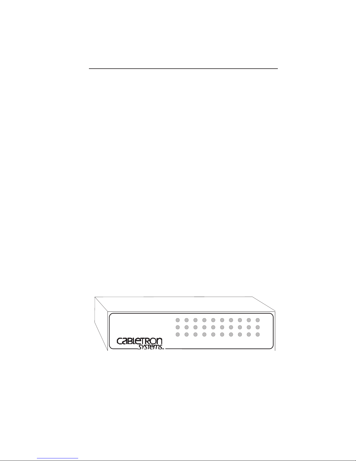
The MR-9000TPT Multiport Repeater can connect up to eight twisted
pair segments to a network segment of the same or different media,
or you can use the MR-9000TPT as a stand-alone repeater for up to
eight twisted pair segments. The MR-9000TPT can
• transmit re-timed data packets
• regenerate preambles
• extend collision fragments
• automatically partition problem segments
• automatically reconnect non-problem segments
The MR-9000TPT Multiport Repeater incorporates Cabletron
Systems’ LANVIEWTM monitoring and diagnostic system. LANVIEW
gives a visual indication of problems such as power failures,
collisions, and cable faults. LANVIEW can alert you to a problem
condition, and indicate the nature of the problem, which streamlines
troubleshooting.
MR-9000TPT
WITH
MULTIPORT ETHERNET/
IEEE 802.3 REPEATER
LANVIEW
TM
PWR
XCVR
PWR
JAM
8 7 6 5 4 3 2 19
RECEIVE
COLLISION
PORT OK
CABLE
SEGMENT
Page 1-1
Page 8

INTRODUCTION
1.2 GETTING HELP
If you need additional support related to the MR-9000TPT, or if you
have any comments, suggestions, or questions concerning this
manual, contact Cabletron Systems Technical Support at
Cabletron Systems
P.O. Box 5005
Rochester, N.H. 03867-0505
Phone: (603) 332-9400
Page 1-2
Page 9

SPECIFICATIONS AND REQUIREMENTS
CHAPTER 2
SPECIFICATIONS AND REQUIREMENTS
2.1 SPECIFICATIONS
Listed below are the electrical and physical specifications of the
MR-9000TPT. Cabletron Systems reserves the right to change these
specifications at any time without notice.
General Specifications
Start of packet delay times
Twisted pair in to
AUI out: 1300 ns max.
Twisted pair in to
twisted pair out: 1450 ns max.
AUI in to
twisted pair out: 1050 ns max.
Collision to JAM delay times
Twisted pair in to
AUI out: 750 ns max.
Twisted pair in to
twisted pair out: 950 ns max.
AUI in to
twisted pair out: 850 ns max.
Preamble
Input: 40 bits minimum to a maximum of 64
bits. Packets that do not meet this
range are discarded as runts or giants.
Output: 64 bits minimum (last 2 bits are 1,1).
JAM output: JAM pattern (1,0) is sent to all
segments when one segment detects a
collision.
Page 2-1
Page 10

SPECIFICATIONS AND REQUIREMENTS
Minimum packet
repeated: 96 bits including preamble. Packet
fragments are extended using the
JAM (1,0) data pattern.
FAULT protection: Segment disconnect occurs after 32
consecutive collisions, or when a
segment’s collision detector is on for
longer than 2 to 3 ms. FAULT
protection resets automatically after
one packet is transmitted onto the
FAULT protected segment without
causing a collision.
RJ-45 Interface (Port 1 - 8)
Transmitter
Bandwidth: 15.0 MHz normal; 13.5 to 16.5 MHz
worst case
Signal amplitude
(balanced): 2.2 V normal; 1.8 to 2.6 V worst case
Idle signal frequency: 1.0 MHz normal; 0.9 to 1.1 MHz worst
case
Idle turn-on delay: 1200 ns normal; 1000 to 1400 ns worst
case
Output impedance: 100 ohm normal; 90 to 110 ohm worst
case
Receiver
Receive threshold: 320 mV
Data frequency: 3.5 to 12 Mb/sec
Common mode
rejection ratio: Greater than 65 dB
Near end crosstalk: -23 dB max.
Input impedance: 100 ohm normal; 90 to 110 ohm worst
case
Internal transceiver: Cabletron Systems TPT-2 transceiver
Page 2-2
Page 11

SPECIFICATIONS AND REQUIREMENTS
RJ-45 Port Pin Configuration
123456 87
Pin 1 RX+
Pin 2 RXPin 3 TX+
Pin 4 No Connection
Pin 5 No Connection
Pin 6 TXPin 7 No Connection
Pin 8 No Connection
Figure 2-1. RJ-45 Pin out
AUI Interface (Port 9)
Frequency range: 4 to 20 MHz normal; 5 to 15 MHz
worst case.
RX and CP pair input
impedance differential: 78 ohms normal; 76 to 80 ohms worst
case
RX and CP pair input
impedance common-mode: Greater than 20.0 ohms
Common-mode voltage
range at RX or CP Pair: 0 to 30 volts normal; 0 to 5 volts worst
case
Input sensitivity at
RX or CP pair: +/-200 mV normal; +/-160
to +/-300 mV worst case
Waveform symmetry
TX Pair: +/-0.5 ns normal; +/-1.0 ns worst case
Output voltage into
78 ohms TX pair: +/-900 mV normal; +/-550 mV worst
case
Page 2-3
Page 12
SPECIFICATIONS AND REQUIREMENTS
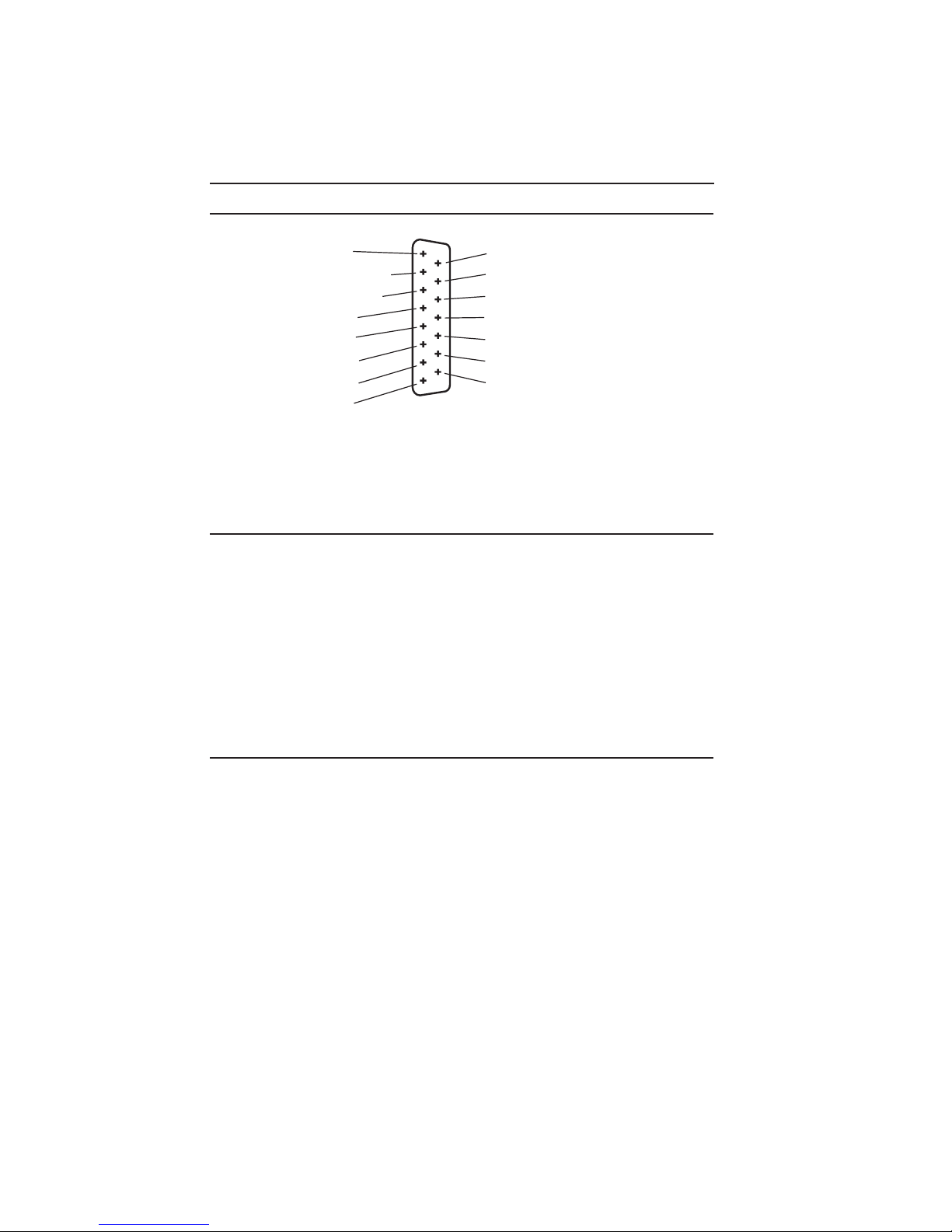
AUI Connector Pin Configuration
8 Logic Ref.
7 No Connection
6 Power Return
5 Receive +
4 Logic Ref.
3 Transmit +
2 Collision +
1 Logic Ref.
15 Position D Type Receptacle
Connector Shell Connected to Case
Figure 2-2. AUI Pin Connections
System Jitter
Into a 300 foot
twisted pair cable: 5 ns.
Into a 150 foot
twisted pair cable: 9 ns.
Into a 6 inch
twisted pair cable: 12 ns.
Bit error rate: 10
9 Collision 10 Transmit 11 Logic Ref.
12 Receive 13 Power (+12VDC)
14 Logic Ref.
15 No Connection
-8
Power Supply
The MR-9000TPT power supply senses and automatically adapts to
the input voltage and frequency.
Input frequency: 47-63 Hz
120 volts nominal: .3 A @ 120V normal; .5 A @ 90 to 130
V worst case
220 volts nominal: .15 A @ 220V normal; .25 A @ 180 to
264 V worst case
Output Voltage: 12 Vdc normal; 11.5 to 15.5 Vdc worst
case
Page 2-4
Page 13

SPECIFICATIONS AND REQUIREMENTS
Power Supply (continued)
Overload protection
Input: (1) 3AG 2 amp fuse (not user
serviceable)
Output: (1) 3AG 1 amp fuse (not user
serviceable)
Environmental Requirements
Operating temperature
range +5o to +40oC
Non-operating
temperature range -30o to +90oC
Operating humidity 5 to 95% (non-condensing)
Safety
Designed in accordance with UL478, UL910, NEC 725-2(b), CSA,
IEC, TUV, VDE class A. Meets FCC part 15, Class A limits.
NOTE: It is the responsibility of the person who sells the system to which
the MR-9000TPT will be a part of to ensure that the total system meets
allowed limits of conducted and radiated emissions.
Service
MTBF (MHBK-217D): > 56,200 hrs. projected
MTTR: < 0.5 hr.
Physical
Dimensions: 3.2H x 15.0W x 12.4D inches (8.13 x
38.1 x 31.5 cm)
Weight: 7 lbs.
Shipping Weight: 8 lbs.
Page 2-5
Page 14

SPECIFICATIONS AND REQUIREMENTS
2.2 NETWORK DESIGN GUIDELINES
Review the guidelines in this section before you install the
MR-9000TPT.
• A shielded twisted pair segment can be no longer than 150
meters (492 feet).
• An unshielded twisted pair segment can be no longer than
100 meters (328 feet).
• A thick-net segment can have a maximum of 100 transceivers,
spaced at least 2.5 meters apart. Transceiver cable taps
should be placed on the black bands on the cable. (The bands
are placed at 2.5 meter intervals.)
• The transceivers that the MR-9000TPT will be connected to
must have their SQE test function turned off.
• The AUI cable that connects the MR-9000TPT to a
transceiver must be IEEE 802.3 type cable and must be 50
meters or less in length.
• From its source address to its destination address, a data
packet may pass through a maximum of four repeaters and
five cable segments. If you use five segments of cable, two of
those segments must be inter-repeater links, that is, point-topoint cable segments with no taps.
2.3 SITE SELECTION GUIDELINES
Before you set up your MR-9000TPT, be sure the selected site meets
the following guidelines.
• The surface area must be at least 21 inches wide, 18 inches
deep and 6 inches high.
• The site must be within 7 feet of an appropriate power outlet.
• The site temperature must be between 5° and 40°C.
Temperature changes must be no greater than 10°C per hour.
Page 2-6
Page 15

INSTALLING THE MR-9000TPT
CHAPTER 3
INSTALLING THE MR-9000TPT
When you unpack the MR-9000TPT, verify that you receive the
following:
• one 8 foot power cord
• one cable support bracket
• two 8/32 x .375 inch screws
• three 6 inch cable ties
The bracket, screws, and cable ties are used to support the cables.
3.1 INSTALLING THE MR-9000TPT
Installing the MR-9000TPT is a simple process of attaching the cable
support bar, plugging in the AUI and twisted pair cables to the
appropriate ports, and then connecting the repeater to an AC power
source.
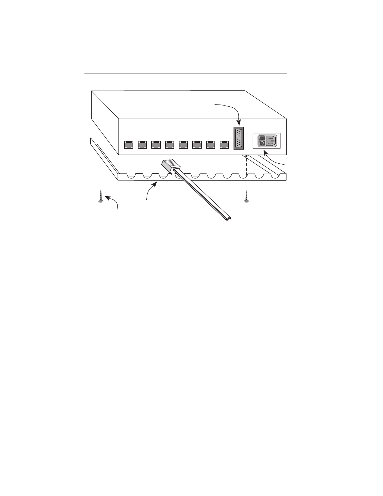
1. Using the two 8/32 inch screws (3, Fig. 3-1), attach the cable
support bar (2) to the repeater.
2. Put the repeater on the selected site. Be sure that the site meets
the guidelines listed in Chapter 2.
3. Attach an AUI cable, no longer than 50 meters in length, to the
AUI port (1) on the repeater.
4. Attach the other end of the AUI cable to an external transceiver.
Refer to the applicable transceiver manual.
CAUTION: You must disable the SQE Test function on the transceiver
connected to the MR-9000TPT. A repeater interprets the SQE test pulse
as a collision and sends out a JAM signal when it detects a SQE pulse.
SQE induced JAM traffic can effectively disable your network. All
Cabletron Systems transceivers have an On/Off switch for the SQE test
function.
Page 3-1
Page 16
INSTALLING THE MR-9000TPT
2
4
3
5. Attach the cable segment(s) to the RJ-45 ports 1 - 8.
6. Plug the power cord into the power receptacle located next to the
On/Off switch (4) on the back of the repeater.
7. Plug the power cord into a wall receptacle.
8. Use the cable ties to provide strain relief for the cables and the
power cord. Strap the cables to the cable support bracket located
on the back of the repeater.
1. AUI Port
2. Cable Support Bar
3. Mounting Screws (2)
4. On/Off Switch
Figure 3-1. Installation
Page 3-2
Page 17
INSTALLING THE MR-9000TPT
3.2 POWERING UP THE MR-9000TPT
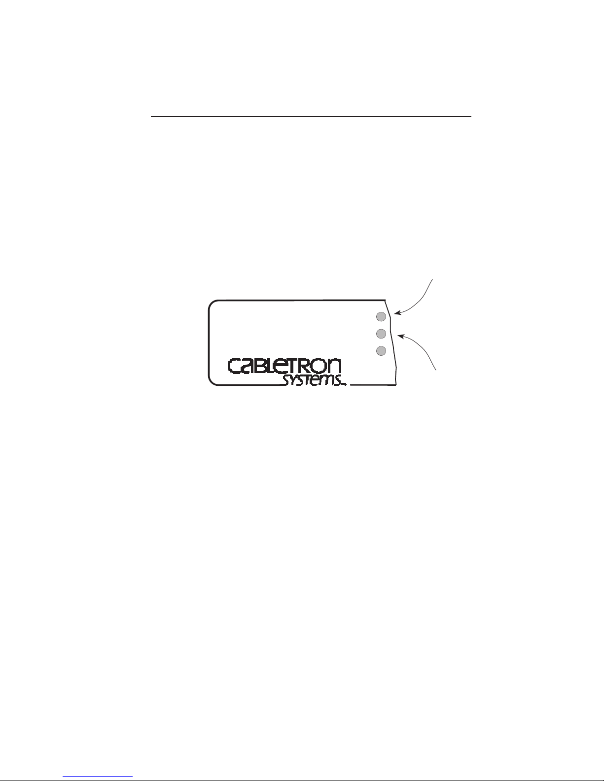
When you turn on the MR-9000TPT, two LEDs on the front panel
should illuminate:
• The PWR LED (1, Fig. 3-2) indicates that the repeater is
receiving power.
• The XCVR PWR LED (2) indicates that the repeater is
providing power to the transceiver connected to the repeater’s
AUI port.
1
MR-9000TPT
WITH
LANVIEW
TM
MULTIPORT ETHERNET/
IEEE 802.3 REPEATER
PWR
XCVR
PWR
JAM
2
Figure 3-2. Power Indicators
Some Port OK LEDs for individual ports may be illuminated as well.
Port OK indicates that the port has a valid network link.
Page 3-3
Page 18

INSTALLING THE MR-9000TPT
Page 3-4
Page 19

USING LANVIEW
CHAPTER 4
USING LANVIEW
This chapter explains how to use the LANVIEW LEDs to help
troubleshoot network problems.
3.1 LANVIEW INDICATORS
LANVIEW is a built-in diagnostic and monitoring system.
Incorporated into the entire Cabletron Systems product line,
LANVIEW lets you quickly scan a series of LEDs to get a sense of
network activity and help you isolate physical layer problems. This
section explains each of the MR-9000TPT LANVIEW LEDs.
Power (PWR)
When lit, this green LED indicates that the MR-9000TPT is receiving
power. The On/Off switch is located on the back of the unit, next to
the power cord connection.
Transceiver Power (XCVR PWR)
When lit, this green LED indicates that the MR-9000TPT is providing
power to the transceiver connected to port 9, the repeater’s AUI port.
Jam (JAM)
When this red LED flashes, the repeater is propagating a collision
from the segment where the collision occurred, to all segments
connected to the repeater. The repeater transmits the jam pattern
(1,0) to all segments when it detects a collision on any segment.
MR-9000TPT
WITH
MULTIPORT ETHERNET/
IEEE 802.3 REPEATER
LANVIEW
TM
PWR
XCVR
PWR
JAM
8 7 6 5 4 3 2 19
RECEIVE
COLLISION
PORT OK
CABLE
SEGMENT
Figure 4-1. LANVIEW LEDs
Page 4-1
Page 20

USING LANVIEW
Receive (RECEIVE)
This yellow LED flashes when the repeater port receives data from
the network. The LED flash is pulse stretched for viewing effect.
Collision (COLLISION)
This red LED flashes when the repeater port detects a collision
condition or a jabber packet on the network. The flash frequency may
increase as network traffic increases since more collisions are likely
to occur. The LED is pulse stretched for viewing effect.
Port OK (PORT OK)
This green LED turns on when the port has a valid connection to a
network device. The repeater disconnects a segment when 32
consecutive collisions occur on the segment or when the collision
detector remains on for longer than 2 to 3 ms.
Page 4-2
Page 21

POWER SUPPLY CORD
The mains cord used with this equipment must be a 2
conductor plus ground type with minimum 0.75 mm square
conductors and must incorporate a standard IEC appliance
coupler on one end and a mains plug on the other end
which is suitable for the use and application of the product
and that is approved for use in the country of application.
GERMAN:
Die Netzleitung, die mit diesem Geraet benuetzt wird, soll
eined zwei Leiter mit Erdleiter haben, wobei die Leiter
mindestens 0.75 mm sind, mit einer normalen IEC
Geraetesteckdose an einem Ende veersehen sind, der fuer
den Gebrauch and die Anwendung des Geraetes geeignet
und der zum Beneutzen im Lande der Anwendung
anerkannt ist.
SPANISH:
El cable principal de la red eléctrica utilizado con este
equipo debe tener 2 conductores y 1 toma de tierra con un
mínimo de 0.75 mm2 cada uno y necesita tener un aparato
de acoplamiento standard IEC en un extremo y un enchufe
para el cable principal de la red eléctrica en el otro extremo,
lo cual sea adecuado para el uso y applicatión del producto
y lo cual sea aprobado para uso en el pais de applicación.
FRENCH:
Le cordon d' alimentation reliant cet appareil au secteur
doit obligatoirement avoir deux fils conducteurs de 0.75
mm2 minimum et un fil de terre. It doit égalament être
équipé du côte apparil d'une fiche agrée IEC et du côte
secteur, d'une prise adaptée à l'usage du produit et aux
normes du pays ù l'appareil est utilisé.
Page 22

 Loading...