

Page 1

MMAC-Plus
™
Module Local Management
9F106-02
Module Specific Appendix
9031681
Page 2

Appendix
9F106-02 Module Specific
Information
Introduction
This appendix contains local management information that is specific to the 9F106-02
FDDI Repeater Module.
1
Page 3
9F106-02 Module Specific Information
Module Specific Configuration Screen
The 9F106-02 FDDI Repeater Module physically attaches to the FNB-1 and the FNB-2
on the MMAC-Plus backplane. By default, the module inserts into four rings (the
primary and secondary rings of the FNB-1 and the FNB-2). The 9F106-02
Configuration Screen allows you to customize this configuration to your particular
needs.
The 9F106-02 Configuration Screen allows you to:
• establish whether the module’s FDDI-1 front panel connections will insert into the
backplane’s FNB-1 (primary and secondary) rings or bypass the FNB-1 rings,
• establish whether the module’s FDDI-2 front panel connections will insert into the
backplane’s FNB-2 (primary and secondary) rings or bypass the FNB-2 rings,
• establish whether or not specific front panel ports and their corresponding FNB
rings will connect only when an active link is detected on the front panel port(s).
The terms INSERT and BYPASS refer to relays that are located on the module.
INSERT causes a relay to connect the module’s specific front panel connections to the
selected ring. BYPASS causes a relay to disconnect the module’s specific front panel
connections from the selected ring.
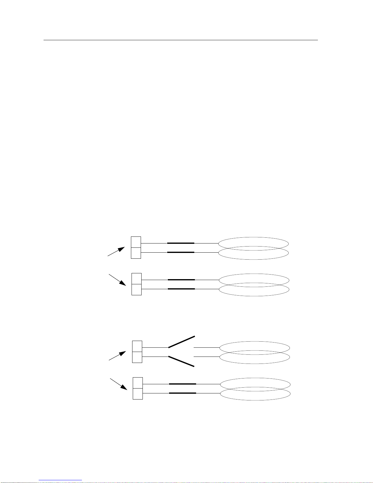
Backplane
FDDI-1
INSERTED
B
FNB-1
A
Front Panel
Connections
INSERTED
B
FDDI-2
FNB-2
A
BYPASS
FDDI-1
B
FNB-1
A
Front Panel
Connections
INSERTED
B
FDDI-2
FNB-2
A
2
Page 4

Appendix
The 9F106-02 Module Specific Configuration Screen displays the current
configuration of the module’s front panel connections in relation to the FNB rings on
the MMAC-Plus backplane, and allows you to change the configuration.
MMAC-Plus LOCAL MANAGEMENT
9F106-02 Configuration
Module Name: 9F106-02 Firmware Revision: 00.00.00
Slot Number: 12 BOOTPROM Revision: 00.00.01
FNB-1
FNB Status: (INSERTED) AutoConnect: (ENABLED)
Port-A Status: Link Port-B Status: No Link
Port-A Type: FPIM-00 Port-B Type: FPIM-02
FNB-2
FNB Status: (BYPASS) AutoConnect: (DISABLED)
Port-A Status: Link Port-B Status: No Link
Port-A Type: FPIM-00 Port-B Type: FPIM-02
SAVE EXIT RETURN
Figure 1.
9F106-02
Module Specific Configuration Screen
3
Page 5

9F106-02 Module Specific Information
9F106-02 Module Specific Configuration Screen Fields
The following information appears on the 9F106-02 Configuration Screen.
(FNB-1) FNB Status is an INSERTED/BYPASS toggle selection which allows you to
control whether or not the module’s FDDI-1 front panel ports will connect (insert) to
the backplane’s FNB-1 rings.
When set to INSERTED, the module’s FDDI-1 (B and A) ports insert directly into the
backplane’s FNB-1 primary and secondary rings, respectively.
Front Panel
FDDI-1
B
INSERTED
A
When set to BYPASS, the module’s FDDI-1 (B and A) ports do not connect to the
backplane. Therefore, no communications between the FDDI-1 front panel ports and
the backplane can occur.
Backplane
FNB-1
Front Panel
FDDI-1
B
BYPASS
Backplane
FNB-1
A
(FNB-1) AutoConnect is an ENABLED/DISABLED toggle selection which allows
you to control whether or not the module’s FDDI-1 front panel ports (in INSERTED
status) and their corresponding FNB-1 rings will automatically connect only when an
active link is detected on the module’s FDDI-1 front panel port(s).
When the (FNB-1) AutoConnect field is set to ENABLED, (and the FNB-1’s FNB
Status is set to INSERTED), then a connection between the module’s FDDI-1 front
panel ports and the backplane’s FNB-1 primary and secondary rings will occur
regardless of an active link being detected on the FDDI-1 front panel port(s).
When the (FNB-1) AutoConnect field is set to DISABLED, (and the FNB-1’s FNB
Status is set to INSERTED), then a connection between the module’s FDDI-1 front
panel ports and the backplane’s FNB-1 primary and secondary rings exist only when
an active link is detected on the FDDI-1 front panel port(s).
(FNB-1) Port -A Status displays the status (Link or No-Link) of the module’s FDDI-1
front panel A port.
(FNB-1) Port -A Type identifies the type of FDDI Port Interface Module (FPIM) that
resides in the module’s FDDI-1 front panel A port.
(FNB-1) Port -B Status displays the status (Link or No-Link) of the module’s FDDI-1
front panel B port.
(FNB-1) Port -B Type identifies the type of FDDI Port Interface Module (FPIM) that
resides in the module’s FDDI-1 front panel B port.
4
Page 6

Appendix
(FNB-2) FNB Status is an INSERTED/BYPASS toggle selection which allows you to
control whether or not the module’s FDDI-2 front panel ports will connect (insert) to
the backplane’s FNB-2 rings.
When set to INSERTED, the module’s FDDI-2 (B and A) ports insert directly into the
backplane’s FNB-2 primary and secondary rings, respectively.
Front Panel
FDDI-2
INSERTED
B
Backplane
FNB-2
A
When set to BYPASS, the module’s FDDI-2 (B and A) ports do not connect to the
backplane. Therefore, no communications between the FDDI-2 front panel ports and
the backplane can occur.
Front Panel
FDDI-2
B
BYPASS
Backplane
FNB-2
A
(FNB-2) AutoConnect is an ENABLED/DISABLED toggle selection which allows
you to control whether or not the module’s FDDI-2 front panel ports (in INSERTED
status) and their corresponding FNB-2 rings will automatically connect only when an
active link is detected on the module’s FDDI-2 front panel port(s).
When the (FNB-2) AutoConnect field is set to ENABLED, (and the FNB-2’s FNB
Status is set to INSERTED), then a connection between the module’s FDDI-2 front
panel ports and the backplane’s FNB-2 primary and secondary rings will occur
regardless of an active link being detected on the FDDI-2 front panel port(s).
When the (FNB-2) AutoConnect field is set to DISABLED, (and the FNB-2’s FNB
Status is set to INSERTED), then a connection between the module’s FDDI-2 front
panel ports and the backplane’s FNB-2 primary and secondary rings exist only when
an active link is detected on the FDDI-2 front panel port(s).
(FNB-2) Port -A Status displays the status (Link or No-Link) of the module’s FDDI-2
front panel A port.
(FNB-2) Port -A Type identifies the type of FDDI Port Interface Module (FPIM) that
resides in the module’s FDDI-2 front panel A port.
(FNB-2) Port -B Status displays the status (Link or No-Link) of the module’s FDDI-2
front panel B port.
(FNB-2) Port -B Type identifies the type of FDDI Port Interface Module (FPIM) that
resides in the module’s FDDI-2 front panel B port.
5
Page 7

9F106-02 Module Specific Information
To edit a toggle selection:
1. Use the arrow keys to highlight the particular value in the field that you want to
change.
2. Use the Space Bar to toggle the value (for example, INSERTED will toggle to
BYPASS).
3. Use the arrow keys to highlight SAVE at the bottom of the screen, then press the
Return key.
When the message “SAVED OK” appears, the edits you have made are saved. If
you exit without saving, the message “NOT SAVED -- PRESS SAVE TO KEEP
CHANGES” appears. If you proceed to exit without saving, your edits will be
lost.
4. Exit the screen by using the arrow keys to highlight RETURN and pressing the
Return key.
6
 Loading...