

Page 1

Cabletron Systems
Networking Guide
MMAC-FNB™ Solutions
Page 2

Page 3

Notice
Cabletron Systems reserves the right to make changes in specifications and other information
contained in this document without prior notice. The reader should in all cases consult Cabletron
Systems to determine whether any such changes have been made.
The hardware, firmware, or software described in this manual is subject to change without notice.
IN NO EVENT SHALL CABLETRON SYSTEMS BE LIABLE FOR ANY INCIDENTAL, INDIRECT,
SPECIAL, OR CONSEQUENTIAL DAMAGES WHATSOEVER (INCLUDING BUT NOT LIMITED
TO LOST PROFITS) ARISING OUT OF OR RELATED TO THIS MANUAL OR THE INFORMATION
CONTAINED IN IT, EVEN IF CABLETRON SYSTEMS HAS BEEN ADVISED OF, KNOWN, OR
SHOULD HAVE KNOWN, THE POSSIBILITY OF SUCH DAMAGES.
Copyright
Printed in the United States of America.
Order Number: 9031706-01 March 1996
Cabletron Systems, Inc.
P.O. Box 5005
Rochester, NH 03866-5005
Cabletron Systems , SPECTRUM , BRIM , DNI , FNB , INA , Integrated Network Architecture ,
LANVIEW , LANVIEW Secure , Multi Media Access Center , MiniMMAC , MicroMMAC , and
TRMM are registered trademarks, and Bridge/Router Interface Modules , CRXMIM , CXRMIM ,
Desktop Network Interface , Distributed LAN Monitoring , Distributed Network Server , DLM ,
EMM-E6 , EMME , EPIM , EPIM-A , EPIM-C , EPIM-F1 , EPIM-F2 , EPIM-F3 , EPIM-T , EPIM-X ,
ESXMIM , ESXMIM-F2 , ETWMIM , FDCMIM-04 , FDCMIM-08 , FDCMIM-24 , FDCMIM-28 ,
FDCMIM-44 , FDCMIM-48 , FDMMIM , FDMMIM-04 , FDMMIM-24, FDMMIM-44, Flexible
Network Bus , FOMIM , FORMIM , HubSTACK , IRBM , IRM , IRM-2 , IRM-3 , Media Interface
Module , MIM , MMAC , MMAC-3 , MMAC-3FNB , MMAC-5 , MMAC-5FNB , MMAC-8 , MMAC8FNB , MMAC-M8FNB , MMAC-Plus , MRX , MRXI , MRXI-24 , Multichannel , NB20E , NB25E , NB30 ,
NB35 , NBR-220/420/620 , RMIM , SecureFast Packet Switching , SFPS , SPECTRUM Element
Manager , SPECTRUM for Open Systems , SPIM-A , SPIM-C , SPIM-F1 , SPIM-F2 , SPIM-T , SPIM-T1 ,
TPMIM , TPMIM-22 , TPMIM-T1 , TPRMIM , TPRMIM-36 , TPT-T , TRBMIM , TRMM-2 , TRMMIM ,
and
1996 by Cabletron Systems, Inc. All rights reserved.
other Cabletron product names are trademarks of Cabletron Systems, Inc.
All other product names mentioned in this document may be trademarks or registered trademarks of
their respective companies.
i
Page 4

ii
Page 5

Chapter 1 Introduction
Using This Guide.........................................................................................................................1-1
Organization of Document.........................................................................................................1-1
Conventions of This Document.................................................................................................1-3
Warnings and Notifications ................................................................................................1-3
Formats and Measures.........................................................................................................1-3
Additional Assistance .................................................................................................................1-4
Associated Documentation ........................................................................................................1-4
Contents
Chapter 2 Overview of Networking
Discussion of Networking..........................................................................................................2-1
Why Network?...................................................................................................................... 2-1
What Is a Network?.....................................................................................................................2-3
The Classification of Networks..................................................................................................2-3
Network Topology ...............................................................................................................2-4
Network Technologies.........................................................................................................2-6
Media......................................................................................................................................2-7
Interoperability and Standards Bodies...................................................................................2-13
Interoperability, the Ideal of Networking.......................................................................2-13
Standards and Compliance...............................................................................................2-13
The OSI Model, Basis of Standards.................................................................................. 2-14
Application of the OSI Model........................................................................................... 2-18
Chapter 3 Technology Basics
Ethernet.........................................................................................................................................3-1
Abstract..................................................................................................................................3-1
Theory .................................................................................................................................... 3-2
Operation...............................................................................................................................3-2
Segmentation.........................................................................................................................3-4
Strengths and Weaknesses ..................................................................................................3-6
Special Design Considerations ........................................................................................... 3-8
Token Ring....................................................................................................................................3-9
Abstract..................................................................................................................................3-9
Theory .................................................................................................................................... 3-9
Operation...............................................................................................................................3-9
Segmentation....................................................................................................................... 3-11
Strengths and Weaknesses ................................................................................................3-13
Special Design Considerations ......................................................................................... 3-15
iii
Page 6

Fiber Distributed Data Interface..............................................................................................3-15
Abstract ................................................................................................................................3-15
Theory ..................................................................................................................................3-15
Operation.............................................................................................................................3-16
Strengths and Weaknesses.................................................................................................3-17
Special Design Considerations .........................................................................................3-18
Chapter 4 Network Design
Workgroup Creation....................................................................................................................4-2
What Is a Workgroup? .........................................................................................................4-2
Workgroup Establishment Criteria....................................................................................4-2
Selecting Workgroup Organization....................................................................................4-7
Selecting Workgroup Technologies..................................................................................4-12
Backbone Planning ....................................................................................................................4-13
What Is a Backbone?...........................................................................................................4-13
Methods of Configuring Backbones ................................................................................4-14
Choosing Backbone Technologies....................................................................................4-17
Creating a Manageable Plan.....................................................................................................4-18
Logical Layout.....................................................................................................................4-19
Fault Aversion .....................................................................................................................4-21
Network Maps and Record Keeping ...............................................................................4-22
Network Expandability.............................................................................................................4-24
Network Migration....................................................................................................................4-24
Designing with the MMAC......................................................................................................4-25
Modular Chassis .................................................................................................................4-25
Reliability and Recovery....................................................................................................4-26
Technology Flexibility........................................................................................................4-27
Power Redundancy ............................................................................................................4-29
Chapter 5 Ethernet
Description....................................................................................................................................5-1
CSMA/CD.............................................................................................................................5-1
Media......................................................................................................................................5-4
Connectivity/Transceivers..................................................................................................5-4
Rules and Regulations .........................................................................................................5-5
Repeating ...............................................................................................................................5-6
Repeaters/Hubs....................................................................................................................5-6
Simple Ethernet Configuration................................................................................................5-10
Design Philosophy..............................................................................................................5-10
Design Example ..................................................................................................................5-10
Segmentation..............................................................................................................................5-15
Bridges..................................................................................................................................5-16
Multichannel Ethernet .......................................................................................................5-21
Segmented Ethernet Configuration.........................................................................................5-23
Design Philosophy..............................................................................................................5-23
Design Example ..................................................................................................................5-24
iv
Page 7

Segmentation - Special Cases...................................................................................................5-30
Port Assignment .................................................................................................................5-30
Port Assignment Configuration............................................................................................... 5-31
Design Philosophy .............................................................................................................5-31
Design Example..................................................................................................................5-32
Ethernet Switching ....................................................................................................................5-34
Switching Configurations......................................................................................................... 5-35
Permutations.......................................................................................................................5-37
Chapter 6 Token Ring
Description ...................................................................................................................................6-1
Fault Isolation .......................................................................................................................6-4
Fault Recovery ......................................................................................................................6-6
Media......................................................................................................................................6-9
Connectivity/Transceivers................................................................................................6-10
Token Ring Network Rules...............................................................................................6-12
Single Ring Configuration........................................................................................................6-13
Design Philosophy .............................................................................................................6-13
Design Example..................................................................................................................6-13
Extending the Ring (Ring-In/Ring-Out)......................................................................... 6-20
Brief Review of MAUs.......................................................................................................6-21
Segmentation..............................................................................................................................6-22
Multi-Ring Configuration.........................................................................................................6-24
Design Philosophy .............................................................................................................6-24
Design Example..................................................................................................................6-24
Multichannel Token Ring..................................................................................................6-33
Multichannel Token Ring Configuration ...............................................................................6-34
Design Philosophy .............................................................................................................6-34
Design Example..................................................................................................................6-35
Chapter 7 FDDI
Description ...................................................................................................................................7-1
Media......................................................................................................................................7-2
Rings and Devices ................................................................................................................7-3
Concentrators........................................................................................................................7-5
Bridges ...................................................................................................................................7-7
FDDI Backbone Configuration ..................................................................................................7-7
Design Philosophy ...............................................................................................................7-7
Design Example....................................................................................................................7-7
FDDI Workgroup Configuration...............................................................................................7-8
Design Philosophy ...............................................................................................................7-8
Design Example....................................................................................................................7-8
v
Page 8

Chapter 8 Expansion - Ethernet
Simple Ethernet............................................................................................................................8-1
Adding Stations ....................................................................................................................8-1
Adding Segmentation..........................................................................................................8-3
Incorporating Token Ring....................................................................................................8-5
Incorporating FDDI..............................................................................................................8-6
Segmented Ethernet.....................................................................................................................8-8
Adding Users to One Segment ...........................................................................................8-8
Adding Users to Several Segments....................................................................................8-9
Incorporating Port Assignment..........................................................................................8-9
Incorporating Token Ring....................................................................................................8-9
Incorporating FDDI............................................................................................................8-10
Port Assignment and Virtual LANs........................................................................................8-11
Adding Users to Any Segment.........................................................................................8-11
Incorporating Token Ring..................................................................................................8-11
Incorporating FDDI............................................................................................................8-11
Chapter 9 Expansion - Token Ring
Single Ring....................................................................................................................................9-1
Adding Stations ....................................................................................................................9-1
Adding New Rings...............................................................................................................9-2
Incorporating New Technologies .......................................................................................9-2
Multi-Ring.....................................................................................................................................9-3
Adding Stations to Any Ring..............................................................................................9-3
Incorporating New Technologies .......................................................................................9-4
Port Assignment...........................................................................................................................9-4
Adding Stations to Any Ring..............................................................................................9-4
Incorporating New Technologies .......................................................................................9-5
Chapter 10 Expansion - FDDI
FDDI Workgroups .....................................................................................................................10-1
Adding Single Attached Stations .....................................................................................10-1
Adding Dual Attached Concentrators.............................................................................10-2
Connecting Multiple Rings ...............................................................................................10-3
Chapter 11 Product Descriptions
Chassis.........................................................................................................................................11-2
Ethernet ....................................................................................................................................... 11-5
Token Ring ................................................................................................................................11-16
FDDI...........................................................................................................................................11-25
Miscellaneous/Multiprotocol................................................................................................ 11-31
vi
Page 9

Appendix A Charts & Tables
Network Design Flowcharts .....................................................................................................A-2
Ethernet Network Design Flowchart................................................................................A-2
ESXMIM Network Design Flowchart...............................................................................A-3
Single Token Ring Network Design Flowchart...............................................................A-4
Segmented Token Ring Network Design Flowchart ......................................................A-5
Multichannel Token Ring Network Design Flowchart ..................................................A-6
FDDI Backbone Network Design Flowchart...................................................................A-7
FDDI Workgroup Network Design...................................................................................A-8
MMAC Design Tables ................................................................................................................A-9
Ethernet Design Tables .......................................................................................................A-9
Token Ring Design Tables ................................................................................................A-13
FDDI Design Tables...........................................................................................................A-16
Networking Standards and Limitations................................................................................A-17
Ethernet...............................................................................................................................A-17
Token Ring..........................................................................................................................A-18
FDDI ....................................................................................................................................A-20
vii
Page 10

viii
Page 11

Introduction
Using This Guide
The purpose of this Networking Guide is to provide the customers and strategic
partners of Cabletron Systems with information which allows them to configure
and expand their own networks. As it is impossible to foresee every possible
situation that may arise when a new network must be created or an existing one
expanded, this guide deals with several of the most common networking
situations.
Chapter 1
If you are unfamiliar with the basics of the Ethernet, Token Ring, and Fiber
Distributed Data Interface (FDDI) networking technologies, read the chapters in
order. Pay particular attention to Chapters 3 through 7. These chapters should
provide you with the basic information necessary to generate a relatively
straightforward network design.
If you have experience with the design or operation of Cabletron networking
products, you may wish to refer mainly to the chapters dealing with the
expansion of existing networks, Chapters 8 through 10.
Organization of Document
In the interests of making this document accessible to as many customers of
differing levels of experience as possible, this Networking Guide begins with a
discussion of the various reasons for networking and a short overview of Local
Area Networks (LANs). Following this brief overview, a series of short,
introductory level training documents is provided. These documents provide
general information on Ethernet, Token Ring and Fiber Distributed Data Interface
networking, including examples of needs analysis and initial network designs
utilizing Cabletron equipment. A short treatment of other networking
technologies follows these individual subsections.
1-1
Page 12

Introduction
Following the discussions of the major networking technologies supported, this
guide shows how networks, based on the examples from the training sections, can
be expanded.
The remainder of this guide contains brief descriptions of Cabletron Systems
modular chassis products, charts and tables which supply much of the
information that the network design process requires, and an extensive glossary
of the terms used within this guide and in other Cabletron Systems publications.
The following summarizes the organization of this manual:
Chapter 1, Introduction, discusses the use and contents of this guide.
Chapter 2, Overview of Networking, explains the fundamentals of Local
Area Networks (LANs), including the reasons to utilize a network, and
discussions of factors such as standards-compliance and interoperability.
Chapter 3, Technology Basics, provides some introductory training into the
LAN technologies which are treated in this Networking Guide.
Chapter 4, Network Design, discusses the procedures and steps involved in
planning out a network, including the selection of a LAN technology and its
organization.
Chapter 5, Ethernet, offers training in greater depth for the Ethernet LAN
technology. This training includes the creation of example network
configurations based on the concepts introduced.
Chapter 6, Token Ring, provides training and configuration instruction for
the Token Ring LAN technology, including example configurations.
Chapter 7, FDDI, is a training chapter which details the operation of the Fiber
Distributed Data Interface (FDDI) technology and the creation of FDDI
networks using Cabletron products.
Chapter 8, Expansion - Ethernet, shows how an existing Ethernet network
can be expanded to include new users or capabilities.
Chapter 9, Expansion - Token Ring, provides instructions and guidelines for
expanding existing Cabletron Token Ring network configurations.
Chapter 10, Expansion - FDDI, describes the means by which FDDI
configurations which use Cabletron products may be expanded to include
new users or stations.
Chapter 11, Product Descriptions, provides short descriptions of many
Cabletron products referred to in this Networking Guide.
Following Chapter 11, Appendix A, Charts & Tables, provides
quickly-accessible tables and flowcharts for network design.
Following Appendix A, the Cabletron Systems Glossary of Terms may be
found.
1-2 Organization of Document
Page 13

Conventions of This Document
Warnings and Notifications
Introduction
NOTE
CAUTION
TIP
Note symbol. Used to provide additional information
concerning subsequent steps or actions that enhance the
operator’s knowledge of the step or action.
Caution symbol. Used to caution against an action that could
result in damage to equipment or poor equipment performance.
!
Tip symbol. Used to convey helpful hints concerning
procedures or actions which would assist the operator in
performing the task in a more timely manner in the future.
Warning symbol. Used to warn against an action that could
result in personal injury or death and equipment damage.
Formats and Measures
Figures throughout the document are identified by chapter and illustration
number. Many figures contain small numbers at the lower right-hand corner of
the illustration. These are Cabletron Systems document control numbers and are
not essential to understanding of the document.
When measurements are given in the text, they will be presented in both metric
and U.S. Customary units. The metric unit will precede the U.S. Customary unit,
and the latter will be contained in parentheses.
References to chapters or sections within this document will be printed in
boldface type.
References to other publications or documents will be printed in italic type.
Conventions of This Document 1-3
Page 14

Introduction
Additional Assistance
This publication describes many possible network configurations and designs.
Due to the nearly limitless possibilities involved in network design, there are
some aspects of the design process which are not addressed in this guide. If you
have any doubts about your configuration or expansion plans, Cabletron Systems
maintains a staff of network design personnel and a sizable team of
highly-trained cabling and hardware installation technicians. The services of the
Networking Services group are available to customers at any time. If you are
interested in obtaining design assistance or a network installation plan from the
Networking Services group, contact your Cabletron Systems sales representative.
In addition to the availability of Networking Services, The Cabletron Systems
Technical Support department is available to answer customer questions
regarding existing Cabletron Systems networks or planned expansion issues.
Contact Cabletron Systems at (603) 335-9400 to reach the Technical Support
department with any specific product-related questions you may have.
Associated Documentation
The following publications may be of assistance to you in the design process.
Several of these documents treat concepts raised in this Networking Guide in
greater detail than they are presented here.
• The Cabletron Systems Product Catalog
1-4 Additional Assistance
Page 15

Chapter 2
Overview of Networking
This chapter introduces and discusses several basic concepts and definitions essential to the
understanding of local area networking.
Discussion of Networking
Why Network?
In this day and age, all companies and agencies have two resources in common,
information and ability. No matter what a company may produce, market, offer or
observe, the final result is one that comes from a combination of ability and
information. Every company with more than one employee is in the business of
sharing information abilities. Information and ability may take many forms: stock
reports and market prediction; manufacturing processes and skilled quality
assurance; accounting information and efficiency examination.
Information is naturally separated from ability. It is the nature of information to
accumulate beyond the point that every person has all the information required to
perform productively. This separation is a factor that has been part of the business
world for centuries. The rise of printing, a postal service, and the telephone can be
viewed as ways that businesses and agencies have created and adopted means of
providing information to those with ability.
While the separation of these factors has always existed and will always exist, the
limiting factor for businesses is not the presence of the separation, but its
magnitude. The more difficult it is to bridge the gap between information and
expertise, the less efficiently both factors are used.
A Local Area Network (LAN) allows for the rapid and direct sharing of critical
information. This sharing enables employees to act more rapidly and with more
complete access to information and resources than may have been possible with a
system of filing cabinets and interoffice mail.
2-1
Page 16

Overview of Networking
The basis of the LAN is sharing. The LAN allows users to transfer information
and completed documents without the overhead and delay introduced by
hardcopy information. In addition, the LAN increases the utility of expensive
resources such as printers, disk arrays, and plotters. For example, a high-speed
printer on every desktop is an expensive and wasteful proposition, but allowing
20 users to share access to one high-speed printer reduces the overall cost of each
document printed.
As very few users create things for only their own use, the LAN allows employees
to discover means to speed the process of work or increase its efficiency. For
example, a document that was once developed, printed, carried to the Order
Entry department, signed, photocopied, sent to the Records department, updated,
and filed can now be printed in all three locations at once, freeing up each
department to perform the tasks it is intended to.
If a LAN is used on a scale that encompasses the entirety of a facility, company, or
corporation, the benefits can be enormous. The nearly instantaneous sharing of
information between several worldwide sites greatly improves the consistency of
company documents and products, provides for the rapid integration of new
policies, and supplies a system for seamless worldwide collaboration on projects.
By reducing the delay inherent in the operations of business, a LAN increases
productivity.
By providing users, management, sales, and production alike, with rapid and
monitored access to the information base on which a corporation is built, a
network empowers employees on a company-wide scale, giving them a chance to
increase their own abilities and use their talents more fully in the corporation. The
LAN is a means of bridging the chasm between information and expertise,
enabling the flow of essential information between workers, departments, offices,
and corporate partners.
The LAN is a means of bringing things together: information and ability,
customers and producers, employees and equipment. In an age where
combination leads to security and strength for corporations, streamlining the
combinations of information and ability helps erase the borders that have
traditionally slowed the business process. By reducing the overhead related in
doing business, a LAN allows your current employees to do more, improving
efficiency and effectiveness to attain greater levels of productivity.
2-2 Discussion of Networking
Page 17

What Is a Network?
Simply put, a Local Area Network, or LAN, is a number of related computers and
electronic devices which share information over a transmission media. This can
be as simple as a series of electronic cash registers which send updates of
products sold during the course of the day to an inventory computer or as
complex as a network spanning an entire corporate facility or University campus,
providing high-powered communication services for hundreds of applications
and the swapping of thousands of files each day.
The Classification of Networks
While all networks are different, they all have a number of common defining
characteristics which serve to illustrate the type of network being discussed or
examined. The most important characteristics for the purposes of this guide are
topology, technology, media, and devices.
For the purposes of explanation, this chapter of the Networking Guide uses one
cohesive metaphor to describe the portions of a network, the “meeting
metaphor.” In the sections which follow, the topologies, technologies, and devices
of networks will be viewed as aspects of a business or public meeting. By viewing
the various facets of a network as parts of one common process, we can describe
the distinct concepts as parts of a larger overall system.
Overview of Networking
What Is a Network? 2-3
Page 18
Overview of Networking
Network T opology
The topology of a network refers to its physical layout or “shape.” The topology
characteristic describes how components and cabling are interconnected. Using
the meeting metaphor, the topology of a network can be seen as the
organizational structure of the meeting itself; will the meeting consist of several
committees making reports to each other when necessary? Will pre-determined
representatives speak for the members of their group? Will an intermediary or
moderator determine who has the “floor,” or will the opportunity to speak pass
from participant to participant in a particular order?
Although the growing complexity and scale of networks has caused some
topologies to bleed over into others, the topologies can be useful starting points
for describing the overall layout of a network or network segment. There are a
number of widely used topology descriptions for the most common topologies
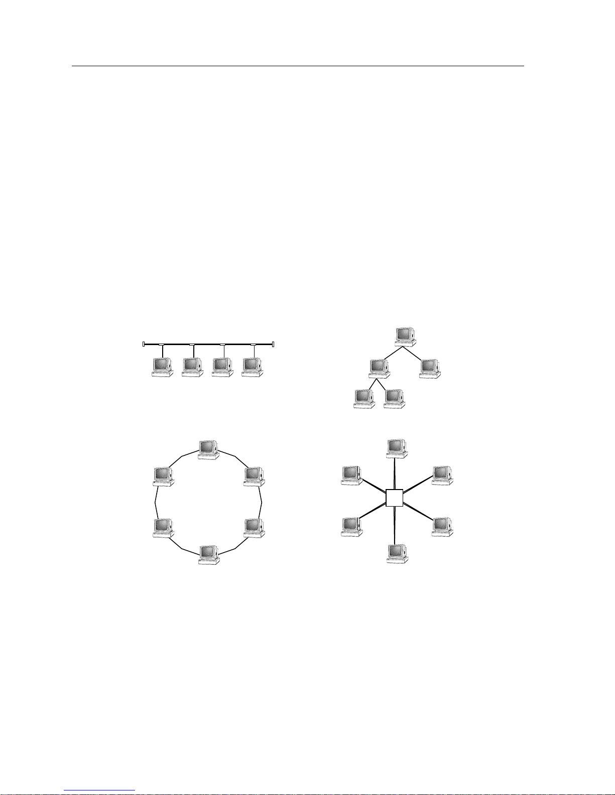
(see Figure 2-1).
Tree
Bus
Ring
Figure 2-1. Network Topologies
Star
Hub
1706n01
2-4 The Classification of Networks
Page 19

Bus
Tree
Overview of Networking
The bus topology uses a single common cable or link (coaxial cable, broadcast
radio frequency) to connect the stations of the network to one another. The bus
topology is strictly an Ethernet phenomenon, and is frequently encountered in
existing Ethernet environments. Stations connect to the common media through a
series of taps, located a specified distance from one another along the common
cable, and only one station may successfully transmit onto the common media at
any one time. Bus topologies are noted for their simplicity, but are notoriously
difficult to troubleshoot. In addition, a failure of the bus media itself, due to
disruption or poor configuration, causes the network to cease functioning.
The tree topology arranges links and stations into distinct hierarchies in order to
allow greater control and troubleshooting. In order to function well, networks
using tree topologies must incorporate some form of “traffic control,”
determining when traffic is allowed to travel up and down the branches of the
tree. Similar to a well-defined chain of command, the tree topology shields
disparate network groups from affecting each other.
Ring
The tree topology also facilitates much more straightforward troubleshooting
procedures. The main downfall of the tree topology is its own organization. If
there is a failure on one of the branches of the tree, every branch that forks from
that point of failure becomes unable to communicate with the rest of the network.
The ring topology connects every station on the network to every other station in
the network in a contiguous circle. Most common in the Token Ring and FDDI
network technologies (discussed later), ring topologies rely on well-defined rules
of transmission and reception in order to function. Stations are connected in a
definite series, with information going from one station to the next in a
pre-defined order. Since each station is expecting transmissions from the station
before it and sending transmissions only to the station following it, ring
topologies can be made to incorporate automatic fault location and recovery
procedures.
The Classification of Networks 2-5
Page 20

Overview of Networking
Star
The star topology consists of a number of individual stations which communicate
through a common central point. Similar to the bus topology, star topology
network stations all share a single common interface. In place of a section of cable,
however, the common central point in star topology networks is often a
concentrator device, or “hub.” Each station connects to the hub through its own
physical interface, and many concentrators incorporate their own troubleshooting
and monitoring functions, allowing network managers to determine faulty
stations and remove them from the concentrator without disrupting the
remaining network. Unfortunately, a failure of the concentrator can lead to the
same disabling of the network that can occur in bus topologies.
Hybrid
Any network topology that incorporates elements of two or more of the
previously discussed topologies is a hybrid. For example, a tree that led down to a
series of buses (the ‘leaves’) would be a hybrid called a “tree of buses.” A ring
topology network with a series of concentrators acting as stations on the ring
would be called a “ring of stars.” As networks grow to encompass more and more
of a facility’s needs, topologies tend to hybridize in order to fulfill the individual
needs of workgroups and departments.
Network Technologies
While a topology describes the way a network is physically laid out, the network
technology defines how the devices that make up the network receive and
transmit information, deal with faults and problems, and control the actual
operation of the network. The technology of the network can be seen as the Rules
of Order that will be followed at the meeting. These concrete and binding rules
will determine who may speak, at what time, for how long, to whom, in what
language, and so on. The technology determines how problems are identified and
what methods may be used to resolve them. If arm wrestling is going to be
considered a valid means of breaking a deadlock between two sides in a vote, the
rules of order must clearly state that, as well as provide the rules for arm
wrestling.
There are several commonly-encountered technologies in networking. Among the
most common of the ‘client-server’ (non mainframe-terminals) technologies are
Ethernet, Token Ring, and the Fiber Distributed Data Interface (FDDI). These
network technologies and their operation are individually described in their own
chapters later in this document.
2-6 The Classification of Networks
Page 21

Media
Overview of Networking
The term media has come to mean several different things in today’s English
language. For the purposes of networking, media always refers to the physical
entity that is used for the purposes of transmitting and receiving the impulses
that make up data exchange. While in some networks, radio frequencies and
nationwide telephone service providers are considered to be media, the term
most commonly refers to the physical chunks of cable that connect one network
device to another. In the meeting metaphor, media is simply the communications
system that is to be used, be it speech, writing, or tin-can telephone.
While media can conceivably be any system of physically transmitting the
impulses indicating the zeroes and ones of electronic data, there are a number of
media common to most networks. Unshielded Twisted Pair cabling, or UTP, is a
commonly-used media in networks. UTP is small-gauge, inexpensive cabling
made up of a series of copper strands which are twisted together inside the
insulating jacket, in the same manner as many telephone cables are. Several
Ethernet networks use telephone-grade UTP as their primary media. Other
common media include coaxial cable, fiber optics (both Light Emitting Diode and
Laser driven), Shielded Twisted Pair (STP), and specific technology-related cable
types such as the Attachment Unit Interface (AUI) cable defined in the Ethernet
technology specification.
It is important to note that some media are not supported by some technologies.
For example; neither the Token Ring nor FDDI standards support the use of
coaxial cables. Each technology will define what media it supports, and to what
extent. Some technologies are very demanding of certain types of media, and all
technologies place limitations on the extent to which a particular media may be
used. These limitations, for the purposes of designing networks, are discussed in
greater detail within the chapters providing individual descriptions of the major
networking technologies, as well as in the Charts and Tables section at the end of
this Networking Guide.
This guide does not intend to describe in detail the procedures for cable
installation and testing. Characteristic properties of the individual media and any
special installation-related information that should be kept in mind during
planning will be presented. This information should be used to assist the selection
of a media based on the needs of a specific location to be networked.
To provide a rough footing, a brief description of each of the cabling media to be
referred to within this Networking Guide follows.
Do not run electrically conductive cabling (cable media with
metal strands or shielding) between buildings. Exposed
conductive cabling is susceptible to lightning strikes.
The Classification of Networks 2-7
Page 22
Overview of Networking
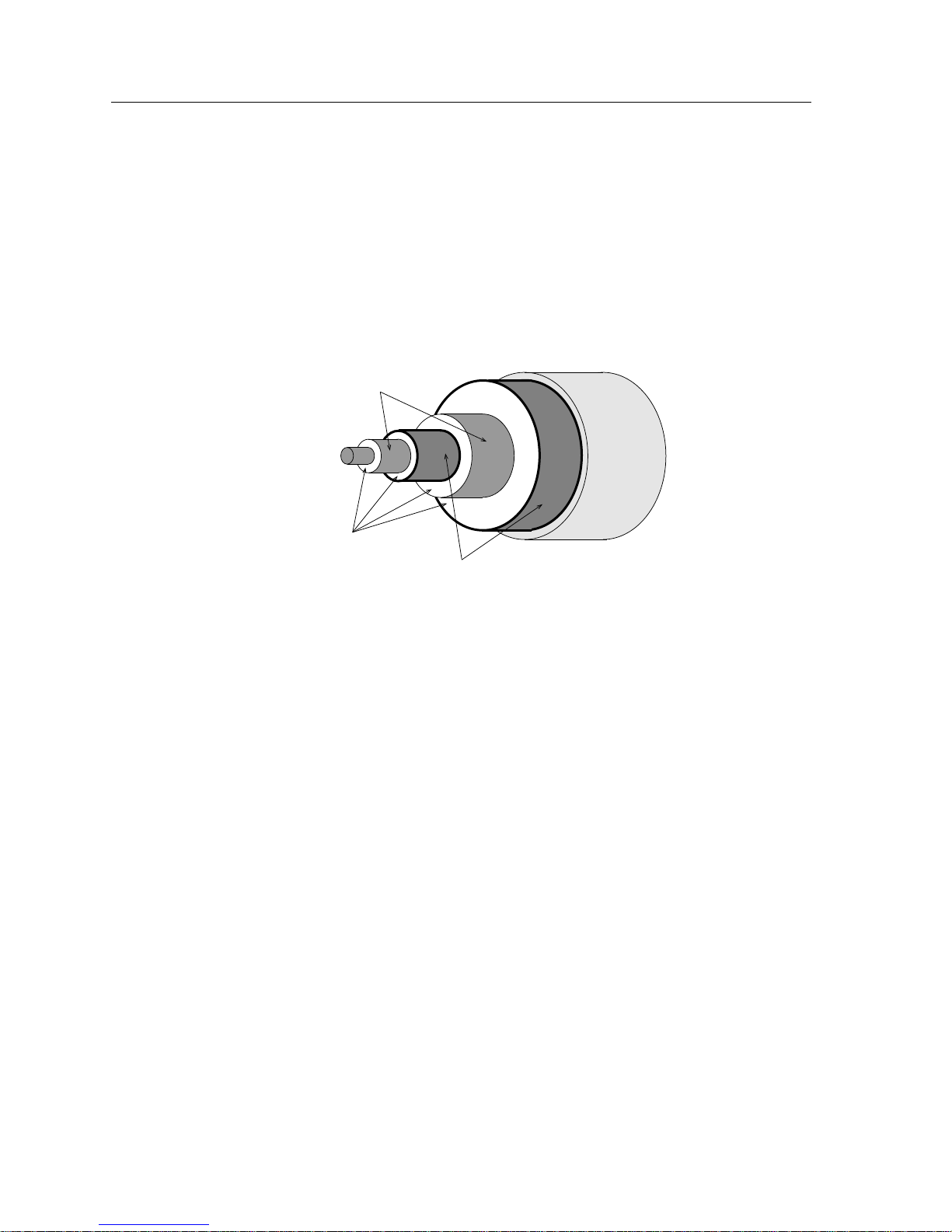
Thick Coaxial Cable
Thick coaxial cable (also known as thick Ethernet cable, “thicknet”, or 10BASE5
cable) is a cable constructed with a single solid core, which carries the network
signals, and a series of layers of shielding and insulator material. The shielding of
thick coaxial cable consists of four stages. The outermost shield is a braided metal
screen. Working inward, the second stage shield is usually a metal foil, but in
some brands of coaxial cable may be made up of a second screen. The third stage
consists of a second braided shield followed by the fourth stage, a second foil
shield. The various shields are separated by non-conductive insulator materials.
Foil Shield
Solid Core
Outer
Jacket
Insulator
Braided Shield
1706n02
Figure 2-2. Thick Coaxial Cable Cross-Section
Thick coaxial cable is a media used exclusively in Ethernet installations,
commonly as a backbone media. Transceivers (devices designed to TRANSmit
and reCIEVE network signals) are connected to the cable at specified distances
from one another, and standard transceiver (AUI) cables connect these
transceivers to the network devices.
Due to the extensive shielding, thick coaxial cable is highly resistant to electrical
interference by outside sources such as lighting, machinery, etc. Because of the
bulkiness and limited flexibility of the cable (typically 0.405 inch in diameter or
thicker), thick coaxial cable is primarily used as a backbone media and is placed in
cable runways or laid above ceiling tiles to keep it out of the way. The 10BASE5
standard, which standardizes minimum and maximum characteristics for
Ethernet networks using thick coaxial cable, specifies a maximum cable length of
500meters (1,640 ft).
Thick coaxial cable is designed to be accessed as a shared media. Multiple
transceivers can be attached to the thick coaxial cable at multiple points along the
cable itself.
2-8 The Classification of Networks
Page 23

Thin Coaxial Cable
Overview of Networking
Thin coaxial cable (also known as thin Ethernet cable, “thinnet,” “cheapernet,”
RG58 A/U, BNC or 10BASE2 cable) is a less shielded, and thus less expensive,
type of coaxial cabling. Also used exclusively for Ethernet networks, thin coaxial
cable is smaller, lighter, and more flexible than thick coaxial cable. The cable itself
resembles (but is not identical to) television coaxial cable.
Thin coaxial cable is made up of a single outer copper shield, which may be
braided or foil, a layer beneath that of non-conductive dielectric material, and a
stranded center conductor. This shielding makes thin coaxial cable resistant to
electromagnetic interference as the shielding of thick coaxial cable does, but does
not provide the same extent of protection. Thin coaxial cable can be run to a
maximum length of 185 meters (606.7 ft.).
As with thick coaxial cable, thin coaxial cable allows multiple devices to connect
to a single cable. Up to 30 transceivers may be connected to a single length of thin
coaxial cable, spaced a minimum of 0.5 meter from one another. Connections to
the cable are typically made using T-connectors, which provide taps for
additional runs of coaxial cable to workstations or network devices. T-connectors,
as shown in Figure 2-3, below, provide three RG58 connections, two of which
attach to RG58 female connectors on the cable itself and one of which is used for
connection to the male RG58 connection of a transceiver or Desktop Network
Interface Card on a workstation.
Front
Side
Bottom
1706n03
Figure 2-3. Thin Coaxial Cable T-Connector
The Classification of Networks 2-9
Page 24

Overview of Networking
Attachment Unit Interface (AUI)
Attachment Unit Interface cable (referred to hereafter as AUI cable, but which
may also be called office transceiver cable or standard transceiver cable in other
publications) is a shielded, multistranded cable that is used to connect Ethernet
network devices to Ethernet transceivers. AUI cable should be used for no other
purpose.
AUI cable is made up of four individually shielded pairs of wire surrounded by
an overall cable shielding sheath. The gauge of the internal cables determines the
thickness and relative flexibility of the AUI cable. Heavy-gauge AUI cable
(containing pairs of wire of 20 or 22 AWG wire) is capable of reaching a maximum
distance of 50 meters (164 ft.) between transceivers and the network device, but is
thick, and somewhat inflexible. The lighter-gauge AUI cable (consisting of 28
AWG wire) is thinner and much more flexible, but can only be run to a maximum
distance of 16.5 meters (54.1 ft.).
Unshielded Twisted Pair (UTP)
Unshielded Twisted Pair cabling (referred to here as UTP, but also may be termed
copper wire, 10BASE-T wire, Category 3, 4, or 5 Ethernet wire, telephone cable, or
twisted pair without shielded or unshielded qualifier) is commonly made up of
two or, ideally, four pairs of 22, 24 or 26 AWG unshielded copper solid or stranded
wires. These pairs of wires are twisted together throughout the length of the
cable. The twisting of associated pairs helps to reduce the interference of the other
strands of wire throughout the cable. UTP cable used in network installations is
the same type of cable used in the installation of telephone lines within buildings.
Tx+
Tx-
RxRx+
1706n04
Figure 2-4. UTP Pair Association
As UTP cabling already exists in many facilities, and as it is inexpensive, available
in bulk and easy to install, the use of twisted pair cabling is often a significant
savings over the use of other media in a networking installation. As UTP cabling
is an accepted media in all common network technologies, it is considered a
somewhat ‘future-proof’ media. In opposition to a length of thin coaxial cable,
which can only be used for Ethernet communications between devices, UTP
cabling could initially be used for Ethernet, then be used to support Token Ring
and FDDI network equipment as the network grew.
2-10 The Classification of Networks
Page 25

UTP cabling is differentiated by the quality of the cable. UTP is divided into
Categories, which indicate the relative quality of the materials used and the
processes used to manufacture the cables. The categories used in LANs range
from Category 3 to Category 5, with Category 5 being the highest quality.
Shielded Twisted Pair (STP)
Shielded Twisted Pair cabling (referred to in this document as STP, but also seen
as “IBM-type” cable or “shielded copper”) is a cable type which is constructed in
much the same fashion as UTP cabling (see Figure 2-4) but incorporates more
elaborate shielding methods. These cables are most commonly used in Token
Ring networks.
As with UTP cable, STP cable consists of two or more pairs of wire. Each wire is
shielded with a layer of insulation, twisted together with a related wire, then
bundled with the other pairs and wrapped in a metal foil. The metal foil provides
additional resistance to the effects of external electrical fields produced by
electrical equipment or other cabling.
STP cabling, like UTP cabling, is divided into groups based on fitness for a
particular purpose. Where UTP referred to Categories of cable, STP cabling is
divided into “types.” These types are based on the IBM Cabling System, and are
often labeled “IBM Type 1 STP.” IBM Type 1 cable is usually the highest quality,
incorporating several layers of shielding and made with heavy-gauge wire, while
Types 6 and 9 STP are usually best suited for use as short jumper cables in
low-interference areas.
Overview of Networking
Fiber Optics
Fiber optic cable is a high performance media constructed of glass or plastic
which uses pulses of light as a transmission method. Because fiber optics do not
use electrical charges to pass data, they are free from the possibility of interference
due to proximity to electrical fields. This, combined with the extremely low rate of
signal degradation and dB loss makes fiber optics able to traverse extremely long
distances. The actual maximums are dependant upon the technology being used,
but distances upwards of 2 kilometers (1.2 miles) are not uncommon.
The Classification of Networks 2-11
Page 26

Overview of Networking
Fiber optic cabling is made up of a glass strand, the core, which allows for the
easy transmission of light; the cladding, a glass layer around the core which helps
keep the light within the core; and a plastic buffer which protects the cable.
Cladding
There are two basic types of fiber optics: multimode and single mode. The names
come from the types of light used in the transmission process.
Multimode Fiber Optics
Multimode fiber optic cabling uses inexpensive Light Emitting Diodes (LEDs) to
produce the signals that travel through the core of the cable. Due to the nature of
the LED, the signal produced is made up of a number of differing wavelengths of
light, fired outward from the center of the LED. Not all the rays of light enter the
fiber, and those that do often do so at an angle, which reduces the amount of
distance the signal can effectively cover.
Single Mode Fiber Optics
Single mode fiber optics, driven by the concentrated beams of light which can
only be produced by lasers, are constructed in the same fashion as multimode
fiber optics, but may use a narrower core strand. The use of lasers to drive the
signal greatly increases the expense involved in producing single mode fiber optic
devices as opposed to multimode fiber optic devices. The expense involved in
single mode fiber optic equipment often causes it to be reserved for applications
requiring its ability to traverse much greater distances than multimode fiber
optics.
Transmissive Core
PVC Buffer (Jacketing)
Figure 2-5. Fiber Optic Cable Cross-Section
1706n05
Single mode fiber optics and their hardware can transmit and receive signals at
distances of 3 kilometers (1.8 miles) or more. As such, it is often best reserved for
extremely long-distance LAN communications.
NOTE
2-12 The Classification of Networks
While the media is capable of supporting these distances, the
technology being used may not be able to function with a link of
that distance. Be sure to remain within the maximum distances and
limitations imposed on any network technology by the appropriate
IEEE or ANSI standard.
Page 27

Interoperability and Standards Bodies
Interoperability, the Ideal of Networking
Ideally, all devices placed on any network should be able to transfer information
in a usable fashion and understandable format to any other station. For some
time, however, this was not always the case. Different companies, even within the
same industry, have different ways of designing, developing, and constructing
their products. Different views of how a network should operate led to radically
different products and methods of networking. These early networking
implementations were specific to one particular vendor, and would often only
work in homogenous environments, where all components used in the network
were produced by that single vendor. This method of networking locked
customers into relying on a single vendor for all of their networking needs,
current and future, which could lead to problems if the network implementation
was unsatisfactory. Ripping out all of your present networking equipment in
order to use the proprietary solution of another vendor can become an extremely
costly proposition.
Overview of Networking
To combat this, the idea of interoperability grew in popularity. Ideally,
interoperability means that the networking devices of Vendor X can
communicate, problem-free, with the networking devices of Vendor Y.
Standards and Compliance
Interoperability requires the following of standards, distinct rules and finite
margins within which network operation and performance must be kept. If a
network does not meet the minimums, or exceeds the maximums of the
networking standard that the industry uses, it is said to be “out of specifications,”
and may not operate at an acceptable level. For example, the Token Ring network
standard specifies the maximum number of stations that may be placed on one
network, or “ring.” If this number of stations is exceeded, the network will suffer
erratic performance and may cease to function correctly. By providing a single
definition for the maximum number of stations per ring, the Token Ring standard
allows devices from multiple vendors to operate in the same fashion.
Standards are defined by committee, through the operation of standards
institutes. Standards institutes are made up of personnel from several firms in the
industry who volunteer their time and effort. These volunteers work to compose
and ratify an acceptable standard, which, when accepted and ratified, will need to
at least be met by any product that refers to itself as “standards-compliant.”
Products that are not standards-compliant may cause or experience
interoperability problems when operating in a standards-based network. Of
course, even in a fully standards-based network, there may still be problems.
Most vendors in the industry, realizing the importance of providing a flexible and
open network to all customers, seek to eliminate any interoperability problems
they notice.
Interoperability and Standards Bodies 2-13
Page 28

Overview of Networking
The most common Local Area Networking technologies (Ethernet, Token Ring,
and FDDI) have standards ratified and in place for their operation and
configuration. ATM, still in the draft stages in some aspects, is operating under a
working interim standard, which is intended to allow ATM equipment to be
produced which will be compatible with future ATM standards. The standards
bodies that this document is concerned with and the standards they oversee are
listed below:
Standards Committee Technology Standard Code
Table 2-1. Networking Standards Bodies
Institute of Electrical and
Electronic Engineers (IEEE)
American National Standards
Institute
ATM Forum Asynchronous Transfer Mode UNI V3.0
Ethernet IEEE 802.3
Token Ring IEEE 802.5
Fiber Distributed Data Interface (FDDI) ANSI X3T9.5
The OSI Model, Basis of Standards
The International Organization for Standardization (ISO) Open Systems
Interconnect (OSI) Model provides a framework for the development of system
connection standards by defining a consistent hierarchy of rules. The OSI model
defines where the needed tasks of system interconnection are performed but not
how they are performed. How tasks are performed on a given layer is determined
by the protocols, or rules, written for that particular network based on the OSI
model. The layers may be implemented in hardware, software, or both. Each layer
in a network based on the OSI model performs specific types of functions
required for proper system interconnection.
2-14 Interoperability and Standards Bodies
Page 29

Overview of Networking
There are seven layers in the OSI Model (see Figure 2-6). They begin with the
Physical Layer and end with the Application Layer. Each layer provides services
to the layer above it. As the seventh layer is the ‘topmost’ layer, it servers the user
directly, and is considered the top of the OSI model.
Application
7.
Presentation
6.
Session
5.
Transport
4.
Network
3.
Data Link
2.
Physical
1.
1706n06
Figure 2-6. OSI Model
Layer Seven: Application
The Application Layer is the user’s interface with the network. This layer directly
interacts with user application programs to provide access to the network. All
other layers exist to support the requirements of the Application layer. The
Application layer is usually involved with network-oriented end-user tasks such
as electronic mail, network file transfers, and collaborative document preparation.
Layer Six: Presentation
The Presentation Layer deals with data translation and code conversion between
devices with different data formats (i.e. ASCII to EBCDIC). This layer also handles
translation between differing device types and file formats, as well as data
encryption and decryption services. In the transmit mode, the presentation layer
passes information from the application layer to the Session layer after it has
appropriately modified or converted the data. In the receive mode, the
Presentation layer works in reverse passing information from the Session layer to
the Application layer.
Layer Five: Session
The Session layer manages the communications dialogue between two
communicating devices. The Session layer establishes rules for initiating and
terminating communications between devices and can provide error recovery.
Interoperability and Standards Bodies 2-15
Page 30

Overview of Networking
Layer Four: Transport
The Transport layer deals with the optimization of data transfer from source to
destination by managing network data flow and implementing the quality of
service requested by the Session layer. The Transport layer determines the packet
size requirements for transmission based on the amount of data to be sent and the
maximum packet size allowed by the network architecture. If the data to be sent is
larger than the maximum packet size allowed on the network, the Transport layer
is responsible for dividing the data into acceptable sizes and sequencing each
packet for transmission.
When receiving data from the Network layer, the Transport layer ensures that the
data is received in order and checks for duplicate and lost packets. If data is
received out of order, the Transport layer correctly orders the data and passes the
data up to the Session layer for additional processing.
Layer Three: Network
The Network layer accepts data from the Transport layer and adds the
appropriate information to the packet to provide proper network routing and
some level of error control. Data is formatted by this layer for the appropriate
communications method, such as IP, IPX, or X.25.
Layer Two: Data Link
The Data Link layer is involved with transmission, error detection, and flow
control of the data. The major function of the Data Link layer is to act as a shield
for the higher layers of the OSI model, controlling the actual processes of
transmission and reception. Error detection and control of the Physical layer are
the primary functions of this layer, ensuring that data received by the upper
layers is error-free. For purposes of understanding networking, it is useful to
divide the Data Link layer into two sub-layers; the Logical Link Control layer and
the Media Access Control layer (see Figure 2-7).
Application
7.
Presentation
6.
Session
5.
Transport
4.
Network
3.
Data Link
2.
Physical
1.
Figure 2-7. Data Link Layer
Logical Link Control
Media Access Control
1706n07
2-16 Interoperability and Standards Bodies
Page 31

Layer One: Physical
Overview of Networking
Logical Link Control: The Logical Link Control sub-layer is responsible for
shielding the upper layers from any particular access method or media. The
upper layers need not worry about wether they are connected to a Token Ring or
Ethernet network because the Logical Link Control sub-layer handles the
interface. The Logical Link Control provides for a common interface of the layers
above to any physical network implementation.
Media Access Control: The Media Access Control, or MAC, sub-layer is
responsible for severla areas of operation. On the transmit side the MAC layer is
responsible for receiving data from the Logical Link Control sub-layer and
encapsulating it into a packet ready for transmission. The MAC sub-layer is also
responsible for determining if the communications channel is available, and for
handling retransmission in the event of a collision on some networks.
At this layer, the transmission of data between devices is defined. That definition
includes cables and connectors, connector pinouts, voltage levels that represent
digital logic levels, bit timing, and the actual network device interface.
Interoperability and Standards Bodies 2-17
Page 32

Overview of Networking
Application of the OSI Model
A user’s perception of network operation appears as direct peer to peer
communications. The user message appears to go from the sending application
directly to the receiving application. In actuality, the user message is routed from
the sending application down through the other OSI Model layers of the system
(see Figure 2-8). Each layer adds to or modifies the message according to the
network operating system’s protocol for each layer. The message passes through
all the layers of the system before appearing on the data channel at the Physical
layer, where transmission and reception of signals takes place.
Application
7.
Presentation
6.
Session
5.
Transport
4.
Network
3.
Data Link
2.
Physical
1.
Perceived Path
Actual Path
Application
7.
Presentation
6.
Session
5.
Transport
4.
Network
3.
Data Link
2.
Physical
1.
1706n08
Figure 2-8. Transmission through OSI Model
From the data channel the message passes upward through the same layers at the
destination device. As the message proceeds from layer to layer, each layer strips
off information that was added by its counterpart in the transmitting station. The
result is the message as it was originally sent, arriving at the destination station’s
Application layer.
2-18 Interoperability and Standards Bodies
Page 33

Chapter 3
Technology Basics
This chapter presents the three main networking technologies that will be discussed throughout this
book. The chapter does not cover these technologies in detail.
This chapter introduces the fundamentals of the technologies to be discussed in
this document. The information is intended to provide a level of basic
understanding of the general operation, capabilities, strengths, and weaknesses of
the three technologies. This is necessary to understand Chapter 4, Network
Design, which deals with the selection of technologies, topologies, and
organization of the network.
Ethernet
Abstract
As this chapter intends to cover only the information necessary to get a start on
the network design process, it specifically avoids detailed discussions and
enumerations of the limits and capacities of Ethernet, Token Ring, and FDDI. For
more detailed information, refer to the more extensive discussions of each
technology contained within chapters 5, 6, and 7.
Ethernet is a local area networking technology that was initially developed in the
1970s by the Xerox Corporation. It is based on the principles of workstations
being responsible for their own transmissions and operation. It is sometimes
referred to as 802.3 networking, in reference to the number of the IEEE standards
body which subsumes all Ethernet operations.
Ethernet networks provide an operating bandwidth of 10 megabits per second
(Mbps). Bandwidth is a networking term which describes the operating speed of a
technology. In the case of Ethernet, a perfectly operating, theoretical Ethernet
network, can move 10,000,000 bits of data between two stations on the network.
3-1
Page 34

Technology Basics
Theory
Ethernet, in its basic form, operates like a series of offices arranged along a central
hallway. Each workstation in an Ethernet network can be viewed as an office
along this giant hallway. When one of these hypothetical offices needs to send
information to another, the worker in the office leans out into the corridor to see if
anyone else is sending a message, takes a deep breath, and yells the message,
which all the other offices receive. Thus, like sound in a corridor, the Ethernet
transmission travels to all the stations on the network. Every person in every
room hears the message and determines if it is for them.
1001011001110110011101000111011001110101
1706n09
Operation
Packets
Figure 3-1. The Ethernet Hallway
Because all the Ethernet stations on the network share this central corridor,
increases in traffic makes the availability of this corridor less and less likely. This
translates to a decrease in the available bandwidth as more stations are added to
the network. While a network may be able to move 9 Mbps with 10 stations on it,
the same network with 300 stations on it may only be able to move 2 or 3 Mbps.
The message that was shouted out into the corridor represents what is called a
packet. A packet is a collection of network data that a station transmits or
receives. It is a series of electrical impulses that represents binary information
(strings of “1”s and “0”s). The Ethernet packet, in the most elementary terms,
contains the following:
• A destination address - Where the packet is headed to
• A source address - Where the packet originated from
• A data field - The content of the message
3-2 Ethernet
Page 35

Procedures
Technology Basics
All the information necessary for a station to receive and comprehend the
network transmission is contained in the packet. The Ethernet packet contains
other fields related to Ethernet operation which are not essential to a basic
understanding of the technology.
Ethernet stations follow four basic procedures when dealing with transmission
and reception. The treatment of these procedures given below is a highly
simplified view of network packet operations. The four procedures are
preparation, transmission, reception, and examination. Preparation and
transmission are both performed by the sending station, while reception and
examination are performed by all receiving stations.
Preparation: When the workstation or device has information that it needs to
send out to the network, it prepares that information for transmission by
generating a packet. The packet, as described above, consists of some network
control information, the station or stations to which the packet must go, the
address of the sending station, and the actual data of the transmission.
Transmission: Once the packet is ready to be transmitted, the Ethernet device
checks its connection to the network. This monitoring determines if the
network is currently being used. If the network is in use, transmitting would
cause both the signals to become garbled. This is called a collision. The
monitoring of the media helps to avoid collisions.
If the media is not in use, the station will add some futrther control
information to the packet, effectively encapsulating it in what is called an
Ethernet frame. Once the frame has been generated, it will be transmitted. It
then returns to monitoring the network to see if the frame it just sent is
involved in a collision. Even though the media was monitored before the
frame was sent, collisions can, and do, still occur in Ethernet networks.
Reception: The frame that has just been sent spreads along the Ethernet
network. As the signal travels throughout the cables and devices, all the
stations on the network read in the entire frame.
Examination: Once a station has received the frame in its entirety, the portion
of the frame that contains the destination address is examined by the
receiving station. If the destination address of the frame matches the address
of the receiving station, the frame is processed. The station removes the frame
information from the transmission, stripping it back down to a packet. The
packet is passed up to the higher layers of the OSI model and the information
in the data portion of the packet is acted upon. If the destination address of
the received frame does not match the address of the receiving station, the
frame is discarded.
More complete treatments of the organization, content, and processing of frames
may be found in documents dedicated exclusively to Ethernet operations. A more
complete depiction of the operation of the Ethernet network technology may be
found in Chapter 5, Ethernet.
Ethernet 3-3
Page 36

Technology Basics
Segmentation
The operation of Ethernet networks is based on the fact that every workstation or
device on the network is connected to every other device on the network. Due to
this treatment, the larger the Ethernet network gets, the more congested it
becomes with added traffic. The added traffic also increases the probability of
collisions occurring. In time, the Ethernet network will grow to encompass so
many stations that it is excessively difficult for a station to receive an opportunity
to transmit frames. The only way to reduce this congestion is by breaking the one
large network up into smaller networks through segmentation.
It is the function of segmentation to separate networks while allowing
information to flow between them when necessary. An Ethernet bridge acts in
much the same way as a bridge in the physical world. It provides a single point of
access between both networks, allowing traffic which must cross to the other
network to do so, while keeping unrelated network activity on one side of the
bridge from impacting the operation of the network on the other side of the
bridge.
Segmentation devices available for Ethernet include bridges, switches, and
routers. While all of these devices perform the same basic function they carry out
the task in different ways and with different results.
Bridges
Bridges operate by reading in frames from one interface to determine if they are
intended for the network they are read from. If the bridge determines that a frame
being examined is, in fact, intended for a station on the network it was received
from, it will discard the frame. After all, the destination station is on the same side
as the transmitting station, and has already received the frame. If, however, the
bridge determines that the destination of the frame is a station which is not on
that network, the bridge will repeat that frame to one of its other interfaces.
In addition, Ethernet bridges can connect an Ethernet network to another
networking technology, provided that the networks are similar. While the
definition of “similar” in respect to bridges is a complex one, we can simplify it
for design purposes: Ethernet, Token Ring, and FDDI are all similar network
technologies from a bridge’s point of view.
This bridging functionality is the basis of creating backbones that use a different
technology than workgroup networks. The most common backbone strategy is to
interconnect several Ethernet workgroups, which operate at a maximum of 10
Mbps, to each other with an FDDI backbone, which operates at 100 Mbps. An
FDDI Management Media Interface Module, or FDMMIM, configured in an
Ethernet chassis would provide the bridging functions necessary to allow the
chassis to connect to such a backbone.
3-4 Ethernet
Page 37

Switches
Routers
Technology Basics
Switches, in an Ethernet environment, act like bridges. A switch connects one
network to another. A switch, however, provides a dedicated connection at full
Ethernet speeds between devices. The important thing to realize about Ethernet
switches is that they may be used in the place of a bridge for the interconnection
of two or more Ethernet networks.
Since most Ethernet switches provide more than two ports for connecting
Ethernet networks, they are often used as outlined in Chapter 5 to provide
connections between high-bandwidth demand workstations.
A router is a network device that performs the same overall functions as a bridge
or a switch, the connection of one network to another. The means by which a
router connects networks together are more complex, however. While bridges and
switches can connect similar networks to each other, routers can connect
dissimilar networks.
Routers are often used in situations where the functions of a bridge would not be
robust enough for the required operations of the network. Routers, by examining
packets of information on the network, can determine not only if those packets
are intended for another network, but what is the shortest path for them to take to
get to their destination. This is accomplished by the router monitoring the
operation of the network and examining each received packet of data in more
detail than a bridge.
The practical upshot of this is that while a bridge is able to operate faster for not
having to perform the same in-depth analysis of every packet that a router must
do, the bridge may not be able to provide the level of efficiency in the utilization
of the network that a router is able to.
Ethernet 3-5
Page 38

Technology Basics
Strengths and Weaknesses
Ethernet
Performance: At 10 Mbps, Ethernet networks are not the fastest category in the
list of LAN technologies, but they are perfectly capable of handling most types of
office and technical traffic.
Reliability: While Ethernet networks are reasonably reliable, they are not always
entirely predictable. Due to the manner in which Ethernet networks handle
congestion and collisions, the network tends to become less available as more
users attempt to transmit frames at the same time. The greater the number of
users, the greater the chance of collisions occurring, and the greater the amount of
waiting for the network to be free for transmission. This translates directly into
delays in network access.
Additionally, the operation and design strategy of the single Ethernet network
can be a reliability problem. Ethernet communications go automatically to all
points on the network. This means that, unless some hardware controls are part of
the network, that an error produced by one station will affect every other station
on the network.
Ease of Configuration: Simple Ethernet networks are very easy to design and set
up. There are a number of well-defined rules set up regarding the maximum
lengths of certain cables and the number of stations that may be serviced by a
single repeater, but these are hard and fast rules which are relatively easy to check
before implementing a network installation.
Troubleshooting: The design of a simple Ethernet network is based on the “many
cables - one LAN” philosophy. Every Ethernet station is connected to every other
Ethernet station through the shared medium of the many cables and repeaters. As
every station is connected to every other station, locating and eliminating
network problems can be difficult, as the search for problem segments, cables, or
devices must begin with the network as a whole. One of the common means of
troubleshooting early Ethernet networks was the “binary debug,” where half the
network would be unplugged or otherwise disabled. If the problem continued, it
was on the half still operating. The remaining portion would then be ‘cut’ in half.
By following this down to its logical conclusion, the segment or segments with
the error condition could be located.
Cost: Ethernet networks are simple, straightforward, and ubiquitous. The
presence of many vendors of Ethernet equipment keeps the prices of components
low in comparison to those required for other networking technologies. Also,
simple Ethernet networks do not require a large investment in networking
hardware to set up. This combination of minimal required hardware and the
availability of that hardware at a low cost makes the simple Ethernet the least
expensive to implement in terms of initial startup expenses. Whether the low cost
of a simple Ethernet is cost-effective is a matter to be determined by the expected
demands that will be placed on the network by its users.
3-6 Ethernet
Page 39

Segmented Ethernet
Technology Basics
Performance: Segmented Ethernet provides the same 10 Mbps that simple
Ethernet networks do, but allows that bandwidth to be more effectively and
efficiently utilized. A bridge connects two separate Ethernet networks. By
separating the Ethernet stations from one another based on a workgroup criteria
(as outlined in Chapter 4, under Workgroup Creation), the segmented Ethernet
design attempts to provide more specialized networks. By making the networks
more specialized, the segmented Ethernet network design allows local network
traffic to circulate without impacting the operation of traffic on other network
segments.
Reliability: By separating the Ethernet network into a number of related
segments, it becomes easier to locate and correct network faults. Since each
network segment is a network in and of itself, a network suffering from an error
condition will not impact the operation of other Ethernet networks to which it is
connected.
Ease of Configuration: Segmented Ethernet networks are relatively easy to
design and configure. The segmentation of the workgroups for the initial
configuration must be carefully thought out and examined in order to achieve an
optimized efficiency. When planning any segmented network, keep in mind that
the more thought that is put into the segmentation of the network, the less
difficult accommodating current and future needs will be.
Troubleshooting: A segmented Ethernet makes troubleshooting, on the whole,
less difficult and network-crippling than a simple Ethernet. Although the
troubleshooting process must include the bridges being used to segment the
network, which are more complicated than repeaters, the division of the network
into segments allows one segment to be examined without being affected by
traffic on other segments, and without the troubleshooting process affecting
error-free segments.
Cost: The addition of bridging to an Ethernet network introduces a number of
hardware and cabling costs. Since the network still utilizes the relatively common
Ethernet hardware and cabling, the costs of the devices are quite low in
comparison to most other technologies. The technology requires a number of
Ethernet networks be set up, which requires the design and configuration of a
number of simple Ethernets. The additional expense comes from purchasing the
bridge or bridges which will perform the interconnection of these network
segments and from the duplication of some cabling in order to set up inter-bridge
connections.
Ethernet 3-7
Page 40

Technology Basics
Switched Ethernet
Performance: Switched Ethernet provides the same 10 Mbps that simple Ethernet
networks do, but allows that bandwidth to be divided in much the same way as
segmented Ethernet (see above). Switches are used to provide dedicated
connections between Ethernet stations and other Ethernet devices. As the
switched connection does not utilize a shared media, the chance of the network
being available for use by the station or device connected to it increases
appreciably.
Reliability: While the inclusion of an Ethernet switch into the network adds
much the same complexity to a network as the addition of a bridge, the overall
reliability of a switched network is greater than that of a simple Ethernet. The
reason for that is the isolation of faulty segments from the rest of the network. A
switch naturally filters Ethernet signals which are not intended for other Ethernet
segments. By including error-checking capabilities into the switching hardware
(which Cabletron Systems switching devices do), network error conditions and
faults can be blocked at the switch before they go on to affect the other Ethernet
segments in the network. In this way, a segment experiencing trouble will not
bring the other segments of the network down. Since each link is a dedicated
connection between two devices, a loss of link should not jeopardize the network.
Ease of Configuration: The design process for a switched Ethernet network is
exactly the same as that for a segmented Ethernet network (see above).
Troubleshooting: Troubleshooting a switched Ethernet network is similar to the
troubleshooting of a segmented Ethernet (see above). One advantage to the
switched Ethernet network design from a troubleshooting point of view is that
Ethernet switches typically provide for the interconnection of more ports from
one device than an Ethernet bridge. This means that the network, as a whole, may
be further segmented or that a port or two on the Ethernet switch can remain
unused as a back-up in the event of a failure of another switch port.
Cost: The expenses inherent in a switched Ethernet network are similar to those of
a segmented Ethernet. The Ethernet switch is relatively expensive, but works with
standard, low-cost Ethernet hardware. The more extensive the use of switching in
the network, the greater the costs will be, due to the requirement of multiple
switches. For example, a network which uses an Ethernet switch to make
connections between a number of single Ethernet hubs will be significantly less
expensive than the same network which uses switches for all connections
between every network device.
Special Design Considerations
• The more stations you have on a single network, the greater the probability of
collisions. Collisions introduce delay and reduce available bandwidth.
• As an Ethernet network grows it remains one segment until that segment is
broken up by a bridge or other segmentation device.
• Any time frames cross a bridge, switch, or router, delay is introduced.
3-8 Ethernet
Page 41

Token Ring
Abstract
Technology Basics
Token Ring is a networking technology developed in the early 1970s by
researchers in Sweden and the United States. The technology was embraced by
IBM, and was standardized in 1985 by the IEEE 802.5 group. The Token Ring
standard is often referred to as the IEEE 802.5 standard.
Token Ring LANs provide an operating bandwidth of either 4 Mbps or 16 Mbps.
The throughput which the network will provide is determined when the network
is designed.
Token Ring is very popular with companies or facilities requiring fault tolerance
and guaranteed throughput under heavy network loads. Customers such as
Insurance Agencies, Banks, or Sales Organizations, which have regular
high-usage periods where delay is detrimental to profit, or mission-critical
networks for facilities such as hospitals, often find Token Ring to be more
beneficial than Ethernet, while being less costly to implement than the much
faster Fiber Distributed Data Interface (FDDI) technology.
Theory
Operation
Rings
Token Ring network operation is based on the principle that the operation of the
entire network determines when a station may transmit and when it will receive.
Stations monitor one another, and one station acts as a ring monitor, keeping track
of important statistics. Token Ring stations are connected to one another in a
predetermined order, and network frames pass from one station to the next,
following that order. A specific, specialized network frame (a collection of data),
called a token, is passed around the ring at regular intervals. The transmission of
the token helps establish some of the operational statistics for the network, and
receiving it allows a station to transmit.
Every station that connects to a Token Ring network is a member of a ring. The
ring is made up of a series of stations which are connected to one another through
a Token Ring device, and the cabling, or media which connects them together. The
ring in Token Ring networks is a single network segment.
Token Ring 3-9
Page 42

Technology Basics
No station may transmit normal data unless it has received the token from the
station before it and ‘claimed’ it by not transmitting the token to the next station.
It then transmits a data frame which is passed from station to station, with each
station receiving the frame, passing it on, then examining the frame to determine
if it is intended for them. If it is, the frame is passed up into the station to be
processed. If the frame is for another station, the Token Ring device discards the
frame and returns to a waiting state.
Direction of data
travel (rotation)
1706n10
Figure 3-2. Token Ring Data Transfer
Once the data frame has been passed around the entire ring, it will return to the
station that sent it. This station, which still holds the token, will examine the
frame and see that it was transmitted from its own location. Seeing this, the
station will strip the frame from the network by not transmitting it to the next
station in the ring. It then releases the token, allowing another station to claim it.
The orderly fashion in which Token Ring networks operate allows them to
incorporate built-in fault location and recovery features. These features help the
network, through its normal operation, to detect problems with stations or
cabling on the ring, and to either correct or bypass them. The fault recovery
process occurs without human intervention, and faulty networks can eliminate
problems without the users ever experiencing a significant loss of network access.
Token Ring is a demanding networking technology which requires strict
adherence to its standards. The operation of the ring introduces a number of
limitations based on time and signal strength, as exceeding the limitations or
falling below required levels can cause the network to malfunction, activating the
fault isolation features. The IEEE 802.5 standard for Token Ring networks places a
number of limitations on things such as the total number of stations on a ring, the
media which may be used to connect them together, and the maximum lengths of
those cables.
3-10 Token Ring
Page 43

Frames
Technology Basics
Token Ring limitations are very restrictive, and all the restrictions are interrelated.
The speed of the network (4 or 16 Mbps), the amount of signal regeneration
performed by the hardware, and the type of media to be used (UTP, STP, or fiber
optics) all act together to determine the total number of stations that a single ring
may support and the maximum lengths of the cabling used to connect those
stations.
The restrictions of the Token Ring standard are covered in detail in Chapter 6,
Token Ring.
A Token Ring frame contains much the same information as an Ethernet frame: a
source address, a destination address, and a data field which contains the packet
that was passed down from the upper layers of the OSI model. The Token Ring
frame also contains a Routing Information Field (discussed later in this section)
and a number of other control and operation related fields which have little
bearing on the network design process.
Segmentation
Bridges
The most common segmentation device in Token Ring networks is the bridge.
Token Ring bridges perform exactly the same function as Ethernet bridges, but
the actual mechanics of segmentation work differently. Where Ethernet bridges
determine to forward frames based on the correlation between the destination
address of a frame and whether that destination address has been seen on the
network the frame originated from, Token Ring bridges allow the frame itself to
tell them where they should be forwarded.
This bridging method is called Source Route Bridging (SR Bridging). It is based on
Token Ring stations sending out a frame that is intended to be received by all
stations on the entire network. The frame is copied and transmitted by all the
bridges on the network, and information is added to the frame each time it passes
over a bridge. The bridge adds its own identification to the frame and sends it on.
Once the frame has reached its destination, the receiving station reads the frame
and examines the list of bridges that the frame passed through during its
transmission. It then builds a routing database that contains the order and
identifications of those bridges. The receiving station then formulates a frame
which contains information for the bridges in the Routing Information Field,
telling each bridge where to send the frame.
Token Ring 3-11
Page 44

Technology Basics
This new frame passes through the network to reach the station which originally
formulated the request, and it builds its own routing database by reversing the
order of the bridge identifications in the Routing Information Field of the frame.
From this point on, the two stations can transmit frames which tell the bridges in
the network what route they need to take.
Because this routing information takes up space in a frame and in the routing
database of each end station, there is a finite number of bridges whose
identifications can be included in the Routing Information Field of a Token Ring
frame. This translates directly into a limitation on the number of bridges that may
be designed into a Token Ring network. An IEEE 802.5 compliant Token Ring
network may contain no more than 14 rings, connected by no more than 13
bridges.
Routers
NOTE
contain no more than eight rings and no more than seven bridges
in its longest path.
A Token Ring router performs the same function as an Ethernet router. It provides
for the interconnection of two or more Token Rings, and transmits frames
between them based on more detailed information than is required by bridges.
This more in-depth information allows routers to be more discerning and precise
with regard to the exchange of frames, but forces them to operate slightly slower
due to the time involved in the examination.
The use of a router or series of routers is the only way to “reset” the 13 bridge rule
described in the Bridges section of this chapter (above).
In order for a network to be IBM Token Ring compatible, it must
3-12 Token Ring
Page 45

Strengths and Weaknesses
Token Ring
Performance: Token Ring networks of all kinds are available in two speeds, 4
Mbps and 16 Mbps. The speed selected determines the rapidity of information
exchange on the network, and also the number of stations which may be present
on the ring (see Chapter 6, under the heading Token Ring Network Rules).
Selection of the ring speed will usually tend towards the higher speed, as that
provides for faster communications between Token Ring stations. The 16 Mbps
speed is half-again faster than the 10 Mbps theoretical maximum of an Ethernet
network, and the performance of a Token Ring network will degrade at a
controlled and predictable rate as the maximum number of stations on the ring is
neared. This provides for a networking technology that is capable of handling a
number of stations with high bandwidth requirements on an even and equal
basis.
Reliability: Token Ring networks incorporate automatic error isolation and
recovery features, which allow a Token Ring network to find and eliminate many
types of common network problems without requiring human intervention.
These capabilities are detailed in Chapter 6, Token Ring. The automatic fault
recovery features greatly increase the reliability of a properly configured Token
Ring network.
Technology Basics
Ease of Configuration: Token Ring networks require extensive planning and
design before they are configured. A large number of rules surround the creation
of Token Ring networks, and these rules change depending upon the operating
speed of the network, the selection of active or passive circuitry, and the selection
of media for the network. Attempting to install an improperly-designed Token
Ring network can be a very frustrating exercise. Due to the complexity of the
network technology, it is not recommended that a Token Ring network be
implemented unless at least one person at the facility, preferably the Network
Manager, has a reasonably good grasp of the concepts and practices of Token Ring
networks.
Troubleshooting: When the automated fault isolation and recovery procedures of
the Token Ring network cannot deal with a network problem, the Token Ring
network can be difficult to troubleshoot. A fatal error condition on the ring will
almost always bring down the entire ring, making a single Token Ring network
unusable until the fault is eliminated. Once again, a firm grasp of the operation of
Token Ring networks will be of great assistance to a Network Manager facing a
Token Ring error situation.
Token Ring 3-13
Page 46

Technology Basics
Cost: Token Ring equipment is inherently more specialized, and often more
complex, than Ethernet equipment with similar capabilities. This, in conjunction
with the relatively smaller number of Token Ring networking hardware suppliers,
tends to make the cost of implementing a Token Ring network more expensive
than the implementation of an Ethernet network with a similar number of users.
As with the complexity of configuration, the cost of Token Ring networking
devices is partially dependent upon the choice of media and the selection of active
or passive circuitry.
Segmented T oken Ring
Performance: Combining the transmission speed and consistent availability of
the Token Ring technology with the segmentation and isolation afforded by
bridging creates a very capable network design. The segmentation of Token Rings
into workgroups provides for greater network availability and for the
configuration of a greater number of workstations and other nodes in the network
as a whole.
Reliability: The automatic fault detection and isolation features of the Token Ring
technology add to the reliability of the multiple bridged Token Ring network. The
incorporation of bridging adds an additional layer of complexity which may be
difficult to manage, but the operation of the bridges keeps network problems on
one Token Ring from affecting other Token Rings in the network.
Ease of Configuration: The segmented Token Ring is the most complex network
technology treated in this Networking Guide. The inherent complexity of design
and configuration of a Token Ring network is added to the requirements of
segmentation and bridging decisions. For those who fully understand the Token
Ring technology, or have some experience designing single Token Ring networks,
the move to a segmented Token Ring network is a simple one. For those with little
or no experience in Token Ring networking, the design of a segmented Token
Ring network is a somewhat intimidating, but by no means impossible, task. As
with all bridged technologies, the use of careful forethought, patience, and
planning will serve to greatly reduce the difficulty of designing a segmented
Token Ring network.
Troubleshooting: The use of multiple Token Ring networks provides for superior
streamlining of the troubleshooting process. The inherent fault isolation and
recovery capabilities of the Token Ring technology, combined with the segment
isolation provided by the use of bridging, allows for the quick and automated
location and elimination of most common error conditions, and the continued
operation of other Token Rings in the event of a fatal error condition on one ring.
Cost: Segmented Token Ring configurations require that a series of individual
Token Ring networks be set up, then connected with Token Ring bridges. These
bridges introduce the additional costs associated with the segmented Token Ring
configuration. As these bridges are reasonably complex devices, the added cost is
not insignificant. Also, whenever a new ring is created, it is necessary to supply a
Token Ring management module to support and initialize the ring.
3-14 Token Ring
Page 47

Special Design Considerations
• The orderly progression of transmission and reception throughout the Token
Ring allows special fault identifications and automatic correction features to be
built into the technology.
• There are limitations to the number of stations on a ring and the distances to
which cabling can be run. These limitations change according to the type of
cable used, the speed of the network, and a number of other factors.
Fiber Distributed Data Interface
Abstract
Fiber Distributed Data Interface, or FDDI, is a high-speed networking technology
which provides a maximum available throughput of 100 Mbps. Due to its high
speed and fault-tolerance, it is often used to connect slower workgroup LANs to
one another.
Technology Basics
Theory
The first portions of an FDDI standard were ratified in 1988 by the American
National Standards Institute, or ANSI. The FDDI Working Group, X3T9.5, for
whom the FDDI standard is named, have continued to release specifications and
updates to make the FDDI technology more accessible and capable for network
operations. Recently, additional specifications have been ratified and published
which detail the use of transmission media other than fiber optics for FDDI
networking. For more information on the standard media which may be used in
an FDDI network, see Chapters 7 and 10.
FDDI LANs operate under the same basic principles as Token Ring networks. The
operating network provides regular opportunities for stations to transmit
information, and each station can expect to receive network data at regular
intervals. A specialized frame of information, also called a token, is passed from
one station to another, traversing the ring in a pre-set amount of time. No station
may transmit unless it has received and “claimed” the token.
Fiber Distributed Data Interface 3-15
Page 48

Technology Basics
Operation
Rings
FDDI operation is based on the movement of data around a series of rings. Like
the organization of the Token Ring technology discussed earlier, FDDI data passes
from one station to another in a predetermined order. In FDDI LANs, there are
two main types of rings: dual counterrotating rings and single rings.
The dual counterrotating ring, hereafter referred to as the dual ring, is the main
ring of an FDDI network. It incorporates the most powerful fault-tolerance
features of the FDDI technology. The dual ring consists of two rings, one designed
to pass data in one direction, one designed to pass it in the opposite direction. If
there is a fault in the dual ring, the network will cause transmissions to wrap from
the primary ring to the secondary ring and travel back along the network,
avoiding the fault and keeping the ring whole.
The dual ring can be connected to a series of single rings, which extend the FDDI
network to many stations. A connection to a single FDDI ring does not provide
the same level of fault-tolerance as a connection to the dual ring, but typically
costs less. Since a series of single rings can be connected to each other through the
dual ring, single ring connections are often used to make connections to
workstations and end users, while the dual ring handles connections between
hubs.
Devices
As there are two types of rings in FDDI networks, there are also two methods that
FDDI devices may use to connect to the network. FDDI device may be
dual-attached, connecting directly to the dual ring, or single-attached, connecting
to a single ring. Dual-attached devices require two FDDI ports, one attaching to
the primary ring and one attaching to the secondary ring. Dual attached devices
are more expensive than single attached devices, but incorporate greater fault
tolerance.
FDDI devices, whether single attached or dual attached, fall into one of two
categories. Any FDDI device which is an endpoint on the network, such as a
workstation or a fileserver, is referred to as a station. Stations may be
dual-attached or single-attached, depending on the connection method they use.
If an FDDI workstation is designed to be connected to the dual counterrotating
rings, it is called a “Dual Attached Station,” abbreviated DAS.
FDDI devices which provide an access point for other FDDI devices are called
concentrators. The typical concentrator connects a series of Single Attached
Stations (SASs) to the FDDI ring. If the concentrator is attached directly to the
dual ring, it is referred to as a Dual Attached Concentrator (DAC).
3-16 Fiber Distributed Data Interface
Page 49

Frames
The FDDI technology collects data into “frames” for transmission. A frame is a
specific format for data and control information. There are two basic types of
frames: network control frames and data frames. Network control frames are
made up of instructions that are intended for the devices on the FDDI network,
informing the stations of changes to the ring or problems with the network. An
example of a network control frame is the token that is passed around the FDDI
ring.
Data frames hold the actual information of the transmission. They are made up of
the basic components of any collection of formatted network data: a source
address, a destination address, and a data field, which contains a packet which
was passed down from the Network Layer of the OSI model. A number of
additional bits of control information are included in the frame for use by the
FDDI stations receiving and transmitting the frame.
Strengths and Weaknesses
Technology Basics
FDDI
Performance: FDDI networks operate at 100 Mbps, ten times faster than the
theoretical maximum of an Ethernet network. While this level of performance is
exceptional and can greatly reduce network access time required to perform
operations, not all workstations are capable of using all 100 Mbps provided by the
network. In some cases, the applications or workstations on your network may
not be robust enough to get the full use out of FDDI. A careful examination of the
amount of networking traffic you expect from the workstations can help you
decide if FDDI will be useful for your network.
Reliability: The reliability of FDDI is one of the key features to consider when
examining the technology. With automatic fault isolation and recovery features
similar to those used in Token Ring networks, but faster and more streamlined,
the technology is one of the most reliable and consistently available networking
technologies today. Add to this the ability to create automatic failover paths for
important devices or connections with a minimum of effort, and FDDI takes the
lead for reliability.
Ease of Configuration: FDDI design and configuration is quite similar to the
design and configuration of Token Ring networks, but with a reduction in overall
complexity. If the connection rules are followed and none of the generous
maximums placed on the number of stations, media used, or distance allowable
are exceeded, configuring an FDDI network is a simple matter of providing
sufficient port count and determining which devices will populate the dual ring
and which will be attached through concentrators.
Fiber Distributed Data Interface 3-17
Page 50

Technology Basics
Troubleshooting: In the event that an FDDI network undergoes a failure, the
network will literally bend over backwards in an effort to keep the network
operating. The exceptionally fast reaction time on station and ring wrapping heals
the FDDI network almost instantly. Multiple faults in the network will eventually
be isolated by the normal operation of the technology. This may sometimes lead
to some unusual network conditions, but the network will try to remain
operational at any cost. Once trouble segments have been located, the relative
scarcity of FDDI troubleshooting devices may increase the time needed to
diagnose and deal with a problem.
Cost: FDDI is expensive. In part due to the complexity and sophistication of the
devices used and in part due to the relatively small installed base of FDDI
networks, FDDI networking hardware remains among the most expensive in the
networking industry. In conjunction with the expense involved in installing and
purchasing fiber optic cabling, the default media for FDDI connections, FDDI is
easily the most expensive standardized technology addressed in this Networking
Guide. This added expense often relegates the FDDI technology to the corporate
or facility backbone network, supplying interconneciton for slower workgroup
LANs.
Special Design Considerations
• FDDI operates like Token Ring, but faster.
• The technology, designed to use the very noise-resistant fiber optic media,
supports very long distances and a large number of stations.
• There are generous maximum limitations to the number of stations on a ring
and the maximum length of an FDDI cable.
• FDDI is expensive when compared to other networking technologies, and is
often used initially as a backbone technology.
3-18 Fiber Distributed Data Interface
Page 51

Chapter 4
Network Design
This chapter deals with the process of visualizing and planning the basic form and operation of a
network.
The network design process is the formation of the network, from initial concept
to the plan of implementation. In this Networking Guide, for the sake of brevity,
the process of network design is separated from the process of network
configuration. Network design is presented and treated as the decisions leading
up to the selection of hardware, and network configuration is the process of
putting hardware together to create a functioning network.
NOTES
As this Networking Guide is concerned with the decisions made regarding
hardware and facility cabling and not with the administration of networks or the
specific uses to which they are put, several aspects of the overall process of
network design are not treated in this document, such as the selection of a
Network Operating System (NOS), the choice of applications or of workstation
types, or other specific decisions generally out of the purview of Cabletron
Systems as a provider of networking hardware.
When designing a network installation or configuration, draw
the network. At the very least, make a rough sketch of each
aspect of the network design process. Seeing the v arious parts
of your design will help you identify strengths and weaknesses
and make it easier for y ou to achieve a grasp of the network as
a whole.
Similarly, draw out the network configuration once you begin
selecting hardware. While it is not necessary to represent
every port, labeling modules and showing the connections
made between them can point out potential problems before
they are cemented into the configuration.
4-1
Page 52

Network Design
Workgroup Creation
What Is a Workgroup?
A workgroup is a group of network end stations that are related in some way. The
conditions of this relationship are determined by the Network Manager, and can
be based on anything from device type to user occupation or even device color. As
the workgroups are the operating portion of the network, where information is
created and given direction, the workgroup is the portion of the network which
creates traffic and network congestion. As such, it is the most complicated portion
of the network to design.
A logical, well-thought-out workgroup plan and a skillful execution of the
creation of workgroups according to a firm set of criteria goes a long way toward
ensuring that the network which results will be functional, flexible, reliable, and
sufficiently robust to handle the demands placed on it by users.
The idea of the workgroup in the network roughly translates to the use of
segmentation. Ideally, segmentation should be planned between separate
workgroups or between collections of related workgroups, not within
workgroups. The workgroup concept divides the network according to a cohesive
plan in the interests of reliability, efficiency, or ease of recovery. While all of these
are important factors in the operation of the network, certain choices made in the
design of networks, from technology and topology to the organization of stations
and the segmentations method used if any, will improve some aspects of the
network at a cost to others. Striking the proper balance of these factors is the
purview of Network Managers, who must investigate and determine the needs
and preferences of the proposed network’s users.
Workgroup Establishment Criteria
This section examines some of the methods that may be used to divide the
population mass of end users of a network into cohesive and defined
workgroups.
Geographical Proximity
Organizing workgroups by geographical proximity creates workgroups made up
of discrete sections of a facility. While in many cases the physical locations of
departments may correspond exactly to a facility layout, the geographical
proximity criteria of workgroup organization does not take function into account.
As the deciding criteria for this type of workgroup organization is location only,
geographical proximity is often the least efficient workgroup creation method in
terms of performance, reliability, and troubleshooting.
4-2 Workgroup Creation
Page 53

Workgroups
Network Design
A8
A7
: Service Workstations
: Sales Workstations
: Research Workstations
: Receiving Workstations
Figure 4-1. Geographical Proximity Workgroups
Having well defined rules of geographical proximity as the deciding factor in
workgroup design does, however, make the physical act of fault recovery easier in
many networks. If an entire location is suffering errors or loss of network
operation, there is a defined physical location to begin examining network
devices for faults.
A6
A5
A4
A3
A2
A1
L1
Corporate Organization
Corporations, companies, and agencies all separate employees by primary
function. No one person “does it all,” and most employees are specialists in the
sense that they perform one function or a series of functions that are assigned to
them by their job descriptions. These functions dictate what types of information
and network utilization they require: manufacturing personnel deal primarily
with manufacturing information; accounting personnel deal primarily with sales,
profit, and expenditure information; and research personnel primarily perform
design and testing operations.
Workgroup Creation 4-3
Page 54

Network Design
Since most of the time business departments are involved with sharing
information among other members of their department or a group of related
departments (Accounting, Personnel, and Payroll, for example), the division of
the end user population into workgroups based on corporate function and
separated by bridges, switches, or routers tends to improve network performance
by keeping information passed within each department from impacting the flow
of information within other departments. This provides natural divisions within
the network for the use of bridging or routing, keeping local traffic from
congesting the network where it is utilized by other departments.
: Sales Workstations
: Research Workstations
: Receiving Workstations
: W orkgroup A
: W orkgroup B
: W orkgroup C
Figure 4-2. Corporate Organization Workgroups
As the creation of workgroups based on departmental organization mirrors the
operation of the company, the expandability of the network is simplified; since
departmental growth can often be predicted in stable or growing companies, the
network can be designed to allow for simplified expansion in the departments
most likely to grow.
Without the use of management software to monitor the operation of workgroups
determined by corporate organization, troubleshooting and fault recovery can be
difficult in a network of this kind. As the end users are not necessarily located in
the same area, faults which affect the workgroup must be looked for in several
locations.
4-4 Workgroup Creation
Page 55
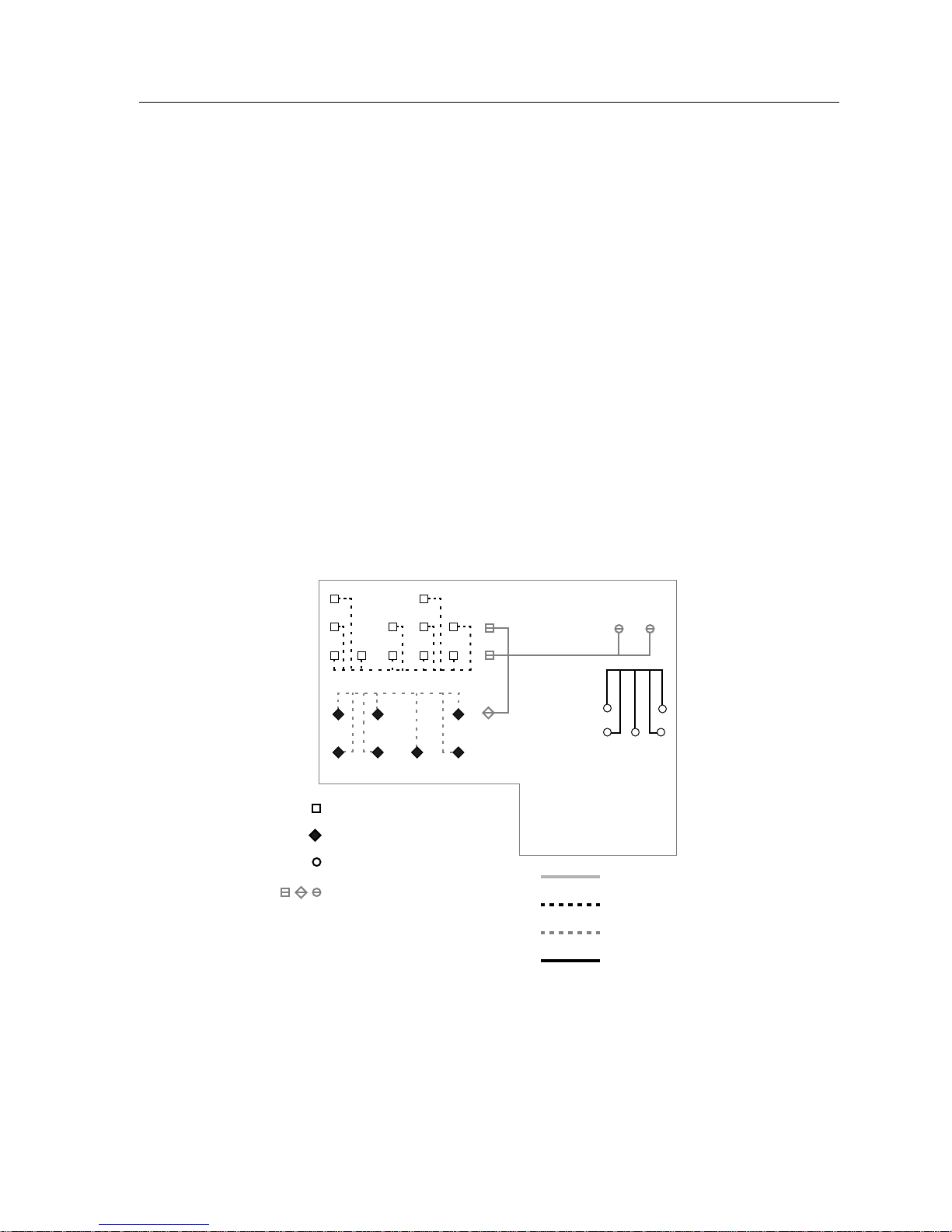
Common Function
Network Design
An even trade-off is made in reliability in networks organized in this fashion.
While the organization of the network into departmental workgroups increases
the inherent complexity of the network by creating several segments based on
function, the loss of a workgroup will disrupt the operation of only that
workgroup, allowing the operation of other workgroups to continue with no
disruption other than the loss of communication with the faulty
workgroup/department.
Segmentation by common function is often used to provide further division of the
network within larger overall departments, or to facilitate the use of certain
network applications by specific end users common throughout much of the
department. An example of this might be the creation of a Documentation
workgroup in a corporation within which each department had a dedicated
Documentation person handling recording and reporting. This would create
workgroups of the members of each department (R&D, Sales, Receiving, etc.) and
one workgroup which encompassed only the Documentation personnel of each
department, who, although working in different departments, all require access to
the same functions through the network.
Workgroup Creation 4-5
: Sales Workstations
: Research Workstations
: Receiving Workstations
: W orkgroup A
: Documentation Personnel
: W orkgroup B
: W orkgroup C
: W orkgroup D
Figure 4-3. Common Function Workgroups
Page 56

Network Design
The creation of workgroups based on common function enhances the
performance of those dedicated functions at a cost to the performance of the
network as a whole. In addition, the management demands placed on a network
by common function networks distributed across an entire facility or corporation
are much the same as those of a corporate organization workgroup scheme, but
even more intense.
Priority Organization
Priority organization is a flexible term which refers to the Network manager
assigning devices to workgroups based on specific priorities. As such, it is the
most flexible scheme for creating workgroups, for it is based solely on the relative
importance of certain network characteristics to individual end users and
equipment. Priority organization can be used to create high-speed,
high-reliability, or rapidly recovering workgroups to those stations which require
those characteristics. Unfortunately, it combines some of the worst features of the
other methods of arranging workgroups as the cost of this level of control.
An example of priority organization is the common practice of connecting all the
file servers for a particular facility to a high-speed network access device in a
single location, regardless of the location of the workgroups which need to access
them. This practice is known as “server farming,” and is used, in many cases, to
keep network users from attempting to repair, reconfigure, or use the servers in
imaginative, and often hazardous, ways.
: Sales Workstations
: Research Workstations
: Receiving Workstations
f/s
: File Servers
Figure 4-4. Priority Organization Workgroups
f/s f/s
f/s
: Priority Workgroup
: Standard Workgroup
4-6 Workgroup Creation
Page 57

Network Design
Priority organization of this manner in a single-segment network involves
providing stations in the priority workgroups with qualities of media and
network connection based on that priority. The stations in the server farm, to
continue with that example, might have redundant connections to the network in
the event that one cable failed, or might utilize a media that is resistant to
interference, such as fiber optic cabling, or might be best served by a centralized
location. A priority organization workgroup or sub-section of a workgroup which
is located on the same network segment as its most common users is usually an
efficient and safe use of resources, and will not impede the operation of the
network.
While keeping the users separate from the devices they need to access on a
regular basis does enhance the Network Manager’s control over its use and
operation, it does reduce network performance in networks utilizing
segmentation. The priority organization method, by connecting stations to the
network based on their relative importance, makes little or no accommodation for
the localization of network traffic which is the purpose of segmentation. If a file
server is located in the server farm workgroup, which is segmented from the rest
of the network, every user needing access to any file server must cross a
segmenting device such as a bridge or switch, which introduces access delays as
the device reads in the packet, examines the packet, determines whether to send it
on or discard it, checks the packet for errors, and acts on its forward or discard
decision. The necessity of crossing the segmenting device on a regular basis
destroys the network availability that is gained by bridging, as local traffic is no
longer kept local.
The use of priority organization also introduces additional troubleshooting
complications. If a station in the Sales department cannot access their file server, is
it because the server has failed, the bridge connecting the server to that
department is in error, the connection from the Sales department to the bridge is
down, or the connection from the employee’s workstation to the rest of the Sales
workgroup is faulty?
Selecting W orkgroup Organization
Once the rules for the creation of workgroups have been cemented and the
Network Manager has determined which end user stations will be members of
which workgroups, the issue of how the workgroups will relate to one another
must be addressed. These relations determine the network equipment required
for the network to operate and for the workgroups to communicate with one
another.
Workgroups can be all grouped together into a single network or separated from
one another by various means. In networks with relatively light network
demands (few users, long periods of light traffic, etc.) a single, unsegmented
network will often provide faster responses than a segmented network of the
same technology. As user counts and network traffic increase, however, the
utilization of segmentation becomes more and more important.
Workgroup Creation 4-7
Page 58

Network Design
Before planning the segmentation of a network, there are a number of things
which should be considered and noted:
• Any locations which have regular and repeated periods of extremely high
traffic (such as computer labs in instructional facilities) cause significant
increases in overall network load unless they are segmented.
• Situations where two separate groups of users require the network without
creating a time overlap can be conducive to the grouping of workgroups
without segmentation.
• Remember the 80/20 rule. Keep approximately 80% of the network traffic in a
workgroup local, and limit traffic which must pass through a bridge, switch or
router to 20% or less.
The organization of workgroups is most effectively made, from an efficiency
standpoint, in a manner similar to the priority organization method of creating
workgroups. Certain workgroups have higher network demands, greater
numbers of users, or more stringent reliability requirements. These workgroups
must be considered for segmentation on a case-by-case basis.
As an example, a facility to be networked has been examined and a workgroup
organization scheme based on common function has been selected. Four
workgroups have been identified: Sales, Customer Service, Records, and
Shipping.
The Sales workgroup is extremely large, made up of more than twice the number
of stations that compose all the other workgroups combined. The Sales
workgroup requires fairly easy access to the network, but does not often need to
communicate with groups other than Shipping.
The Customer Service workgroup, while small, is considered the most important
segment by the Management and the Network Designer.
The Shipping and Records departments are both relatively small. They
communicate with one another often and do not require an extremely
high-performance network connection. After every business day, the Records
department performs a full backup of all the records for that financial quarter, a
process which will flood the network with constant traffic for half an hour or
more.
As the division and organization of this network into workgroups is planned, a
series of illustrations representing the weights of certain network characteristics
will be inserted in the text. In these diagrams, the value of the characteristic being
examined for each proposed workgroup is denoted by size and by shade. The size
of the field of the illustrations is directly proportional to the number of end
stations in each field. When certain characteristics of the network are depicted by
the fields, the darker the shading of the field, the more that field experiences or
embodies the aspect under consideration.
4-8 Workgroup Creation
Page 59

The Initial Field
Network Design
To begin, we gather the requisite information and determine the number of end
stations that the network for this facility will have to support. This gives us the
initial field of the network before any workgroups have been decided upon.
ALL USERS
Having defined the initial field from which workgroups will be built, we then
determine the criteria on which the division of the end stations into workgroups
will take place. In this simplified case, the workgroups will be determined solely
on the basis of department membership, following the corporate organization
workgroup establishment criteria. This produces four workgroups from the initial
single field:
Workgroup Priority
SALES REC SHP
Having divided the network into initial workgroups, we need to examine the
sizes of the workgroups which result. Those workgroups with large numbers of
stations on them may require further segmentation later, while small workgroups
may be able to be combined with other small workgroups. The decision to
attempt further division or combination will have to be made following the
examination of the network and the workgroups on the basis of other
information.
One of these things to be considered is the relative priority of the workgroups.
This priority may be based on network speed and access time, reliability, other
factors, or a combination of such factors. This priority must be determined
relative to the other departments to be networked, not on an absolute basis.
Everyone will consider their workgroup to be the most essential, but detached
decisions must be made regarding these priorities if there is to be any
consideration of priority whatsoever.
In our example network, company policy dictates that the Customer Service
department is the foremost, and requires both fast and reliable access to the
network. This top priority segment is followed in access importance by the Sales
department, which cannot make sales as efficiently without access to the network.
Records and Shipping can both operate without network access for at least a
business day.
C
S
Workgroup Creation 4-9
SALES REC SHP
C
S
Page 60

Network Design
Internal Load
The efficiency and speed of a network is dependent upon the traffic load of that
network. This is one of the primary reasons for bridging; by keeping local traffic
local, the performance of other network segments tends to increase. An
examination of the relative amount of internal traffic each workgroup creates can
indicate which workgroups can be segmented in order to keep them from
affecting the operation of other workgroups. In our example, the Sales
department workgroup produces a vast amount of traffic which remains within
the workgroup, so it becomes a prime candidate for segmentation.
SALES REC SHP
By examining the extent to which each workgroup displays the characteristics
being considered, you can determine which workgroups are candidates for
segmentation from the rest of the network and which are candidates for
combination with other, preferably related, workgroups. You can also spot those
workgroups which may require re-consideration and possible further division
due to large numbers of users or high expected traffic. By determining what
segmentation level, if any, you wish to employ, you can develop the layout of
your workgroups smoothly and effectively.
C
S
ALL USERS
SALES REC SHP
SALES REC SHP
SALES REC SHP
SALES REC SHP
C
S
C
S
C
S
C
S
Size of Workgroup
Required Level of Service
Internal Group Traffic
Sum of Network Demand
(indicates need for segmentation)
External Load
When determining which workgroups will be separated from or combined with
other workgroups, consider the locations where segmentation will be used. Those
workgroups upon which a high percentage of the absolute traffic is intended for
other workgroups should not be separated from the other workgroups by too
much segmentation. If a workgroup which requires constant access to other
workgroups is kept apart from those workgroups by a large number of
segmentation devices, the access time for that workgroup is significantly
increased.
4-10 Workgroup Creation
Page 61

Network Design
SALES REC SHP
Looking at the above example, it makes more sense to keep the Records
Department workgroup ‘close’ to the other segments of the network. Since it
requires access to other segments on a more frequent basis than the others,
keeping the Records workgroup from being segmented an excessive extent will
help to increase the performance of Records department network operations.
bad
SALES 2
b
SALES 1
b
S
b b
C
Access to furthest group through
4 bridges and 3 shared segments
better
SALES 2
b
C
S
b
C
S
better
SALES 2
C
S
RECSHP
SALES 1
Access to furthest group through
2 bridges and 1 shared segment
SHP
bb
REC
best
SALES 2
b
C
S
SALES 1
Access to furthest group through
2 bridges and no shared segments
RECSHP
SALES 1
Access to furthest group through
1 bridge and no shared segments
b
This symbol indicates a bridge
RECSHP
Figure 4-5. Workgroup Proximity Organization
Departments with low network demands, as determined in the previous
discussion, can be combined with those workgroups with frequent inter-group
communications needs, as shown in the example above where the Records and
Shipping workgroups were combined.
Workgroup Creation 4-11
Page 62

Network Design
Selecting W orkgroup T echnologies
The selection of a network technology at the workgroup level is a very important
decision, and one that should be made only after careful consideration and
evaluation. Before deciding on a network technology to be used by the
workgroups, make sure you are familiar with the operation of each type of
technology, the strengths and shortcomings of those technologies, and the special
design considerations that each technology imposes on the network. Chapter 3 is
a good place to go for initial information, but the text deliberately avoids
examining the technologies in great detail. For more detailed treatments of the
technologies, you may wish to refer to Chapters 5, 6, and 7. There are also several
texts on network technologies available through academic and technical
booksellers.
The selection of a workgroup technology is an analysis of functionality. It is the
job of the Network Manager or persons designing the network to determine
which factors of the network design are the foremost requirements.
The most common determining factors in selecting a network technology are
performance (speed of operation), reliability, ease of configuration,
troubleshooting, and cost. Cost is a separate issue from price, as cost is based on
the inherent expenses of the technology, whereas price is highly dependent upon
the vendor supplying the products and the quality of the products and service
associated with them.
Each of these factors in deciding upon a network technology are treated in
Chapter 3, Technology Basics.
This information is not intended to be the only guide for deciding upon a
networking technology. The selection of a technology determines the capabilities
and characteristics of the entire network, and is one of the most important and
long-term decisions you make when designing a network.
For this reason, once you feel you have selected a suitable technology, do further
research on that technology if you have any questions about its operation or the
means by which a network is created using that technology. Contact your
Cabletron Systems Sales Representative for information, or read any of the
technical books available on the subject matter.
4-12 Workgroup Creation
Page 63

Backbone Planning
What Is a Backbone?
A backbone is a network segment or cable which is used to provide for the
interconnection of a number of smaller workgroups or self-contained networks.
The outlying networks, workgroups, or hubs communicate with one another
through the backbone network.
The use of a dedicated network acting as a backbone, tying all the separate
networks together, is of benefit for several reasons.
• Using a single network to handle the extremely important connections
between networks allows Network Designers to utilize highly reliable
technologies and cables. These designs are frequently expensive, and using
them, initially, in the backbone network provides the benefits of these
technologies or media without requiring the expense of providing that level of
service to all points of the network.
• A backbone network can be migrated out to the workgroups as the
facility-wide network grows. As more users are added, it is often much easier
to attach a concentrator or hub to a small backbone network than to continue
expanding workgroups that may be already quite congested. In addition, the
backbone can provide a point from which a higher-speed technology can be
‘painted out’ to the rest of the network as needs dictate and as money becomes
available.
Network Design
• Since the amount of communications passing between several workgroups or
hubs in an entire facility or campus is often quite large, backbone networks
often use higher-speed networking technologies than the technologies used by
the workgroup networks. A very common workgroup and backbone scenario
involves several Ethernet workgroups in a building or campus connected to an
FDDI backbone. This offers the communications passing between the separate
Ethernet networks, operating at under 10 Mbps, to access a highly reliable and
available 100 Mbps network for communications between workgroups.
Backbone Planning 4-13
Page 64
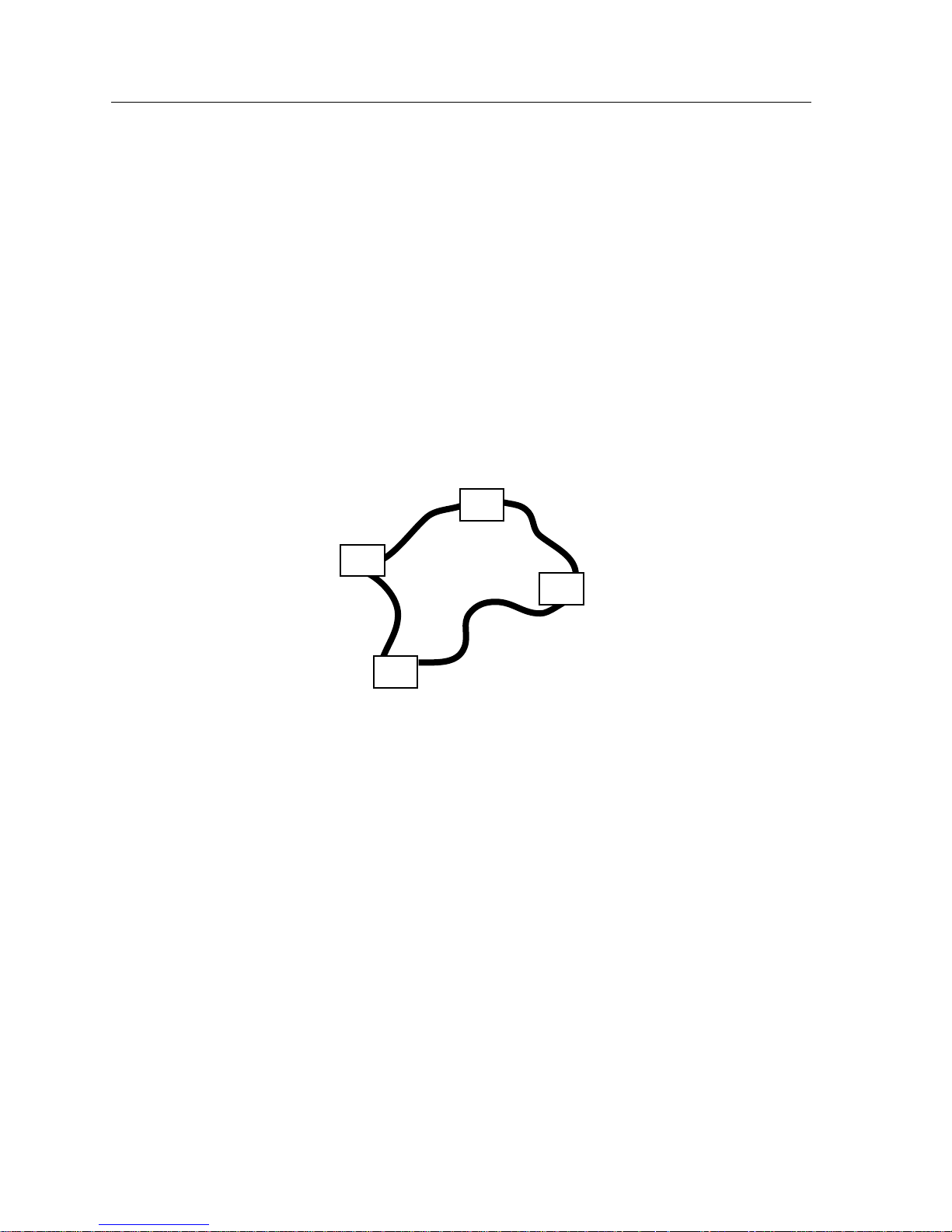
Network Design
Methods of Configuring Backbones
Backbone networks can be set up in a number of different ways. This Networking
Guide will present three of the most common means of configuring backbone
networks. From these three basic types; the distributed backbone, the collapsed
backbone, and the device collapsed backbone, nearly any backbone network
implementation required may be designed.
The Distributed Backbone
One method of creating a backbone network is to sequentially string all of the
workgroup networks or hubs together. Cabling is run from one workgroup hub to
the next, providing the necessary connections. This method of configuring a
backbone network may be used with any technology except ATM, which requires
a device backbone configuration (detailed later in this chapter).
hub
hub
hub
hub
1706n16
Figure 4-6. Distributed Backbone
A distributed backbone is usually the least expensive backbone network selection,
as the only cabling required is that which runs from one workgroup network to
another. The problems inherent in the distributed backbone network are
somewhat limiting, however:
• Connectivity Requirements - FDDI and Token Ring networks must form a
complete, unbroken ring. Ethernet backbones are most effective if all
workgroup networks are attached to a shared bus, such as a thick coaxial cable.
• Limited Expandability - While it is possible to simply add stations to a thick
Ethernet backbone, the ring-dependent technologies (Token Ring and FDDI)
require that existing cable be cut and terminated or replaced with additional
cable runs when new workgroup networks are added to the backbone.
• Troubleshooting Complexity - If a distributed backbone suffers an error or a
faulty cable, locating the fault in the network often takes up much of the total
troubleshooting time. If a cable is at fault, the Network Manager may end up
spending a lot of time pulling and testing new cabling.
4-14 Backbone Planning
Page 65

• Limited Control - The use of a distributed backbone makes the isolation of
workgroups from the rest of the overall network somewhat time-consuming.
If a workgroup in a distributed backbone needs to be disconnected from the
other networks physically, for whatever reason, the distributed backbone
requires that a Network Manager go out to the physical location of the
workgroup network and disconnect the required cables, making any additions
or changes necessary to keep the backbone network whole and operating.
The Collapsed Backbone
It is also possible to run cables from a central point, often a network management
office or central wiring closet, out to each workgroup network and back. These
cabling runs are then terminated at a central point such as a patch panel. The
patch panel ports for each of the cable runs can then be connected to one another
using jumper cables. In this fashion, provided that no technology restrictions are
exceeded, chains and rings of workgroup networks can be created.
Network Design
hub
hub
hub
hub
Cross-Connected
Patch Panel
1706n17
Figure 4-7. Collapsed Backbone
Having the individual cable runs of the backbone connected to one another at a
single point can make this configuration more expensive than the distributed
backbone, but the added configuration and control options provided by the
collapsed backbone often outweighs the associated costs.
• Connectivity Requirements - The collapsed backbone implementation brings
all cables of the backbone to a central point, and the requirements of the Token
Ring and FDDI technologies for an unbroken ring still apply.
Backbone Planning 4-15
Page 66
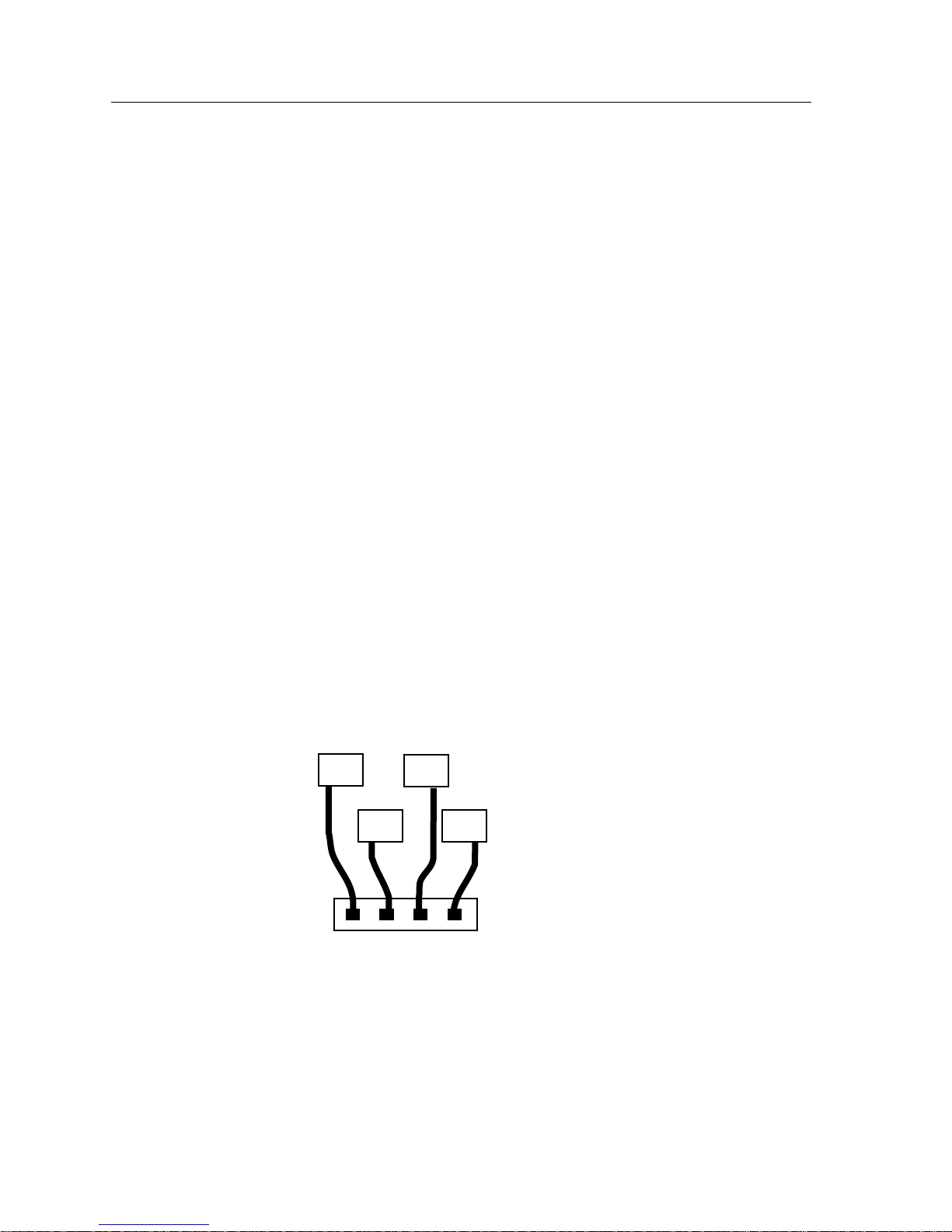
Network Design
• Ease of Expandability - Since the cables of the collapsed backbone originate
from a patch panel in one location, adding new cable runs to accommodate
new workgroups or to bypass outmoded ones is a simple matter of changing
a few jumper cables. If the network cabling was planned far enough in
advance, the facility cabling required to add new workgroups to the backbone
network may be already in place, requiring only a set of jumper cables and a
short amount of time to connect. The use of a collapsed backbone can ease the
transition from a backbone network with no controlling hardware to a device
collapsed backbone in the future.
• Simplified Troubleshooting - Workgroups can be bypassed by simply
re-configuring a single patch panel. This can easily isolate a problem segment
for troubleshooting, and keeps the backbone network from being kept in a
fault condition.
• Moderate Control - The isolation of workgroups and the reorganization of the
backbone network is simplified with the collapsed backbone, but the system
does not incorporate any management features beyond the physical
connections of facility cabling. For advanced and detailed network control
operations, the device collapsed backbone (discussed below) is superior to the
collapsed backbone alone.
Devices as Backbones
Once a collapsed backbone has been designed, it is a simple matter to connect the
multiple backbone cables together through a device. Often this device is a
multiport router, network switch, or a modular chassis. The use of a device of this
type to make the connections between workgroups greatly increases the control
that Network Managers have over the network, and may improve performance
by streamlining the communications between networks.
hub
hub
hub
hub
Ethernet Switch
1706n18
Figure 4-8. Device Collapsed Backbone
4-16 Backbone Planning
Page 67

Network Design
The device collapsed backbone is the most expensive backbone choice, simply
due to adding the cost of sophisticated, high-performance hardware to the costs
of a collapsed backbone cabling layout. In many cases, the additional control and
functionality provided by the device collapsed backbone configuration are so
valuable that the cost is well worth it.
• Connectivity Requirements - The device collapsed backbone implementation
brings all cables of the backbone to a single device, which takes care of the
interconnection issues.
• Ease of Expandability - As all the workgroups of the network are connected
through the backbone device, the expandability of the network is limited by
the amount of expandability that the device is capable of. As with the design
of facility cabling, planning for future needs will go a long way toward
reducing future expenses and possibly avoiding a costly “forklift” upgrade.
• Simplified Troubleshooting - The device collapsed backbone, by connecting
the workgroups through a manageable device, provides not only simplified
troubleshooting, but the ability to detect some backbone faults before they
become network failures.
• Extensive Control - The device collapsed backbone provides the highest level
of network control. Workgroups and devices on the backbone can be included
or bypassed with the click of a mouse or through the use of a terminal session.
Physically adding workgroups to the network will still require the connection
of facility cabling and jumper cables, but, as with the standard collapsed
backbone, the usefulness of planning ahead cannot be over-emphasized.
One danger of the device collapsed backbone is the existence of a single point of
failure: the backbone device. If the backbone device fails, the backbone network
will not operate. For more information on single points of failure and avoiding
their creation in a network, refer to the Fault Aversion section of this chapter.
Choosing Backbone Technologies
The selection of a backbone technology is a similar process to the selection of
workgroup technologies. As with the selection of a workgroup technology, make
sure you are familiar with the operation of each type of technology, the strengths
and shortcomings of those technologies, and the special design considerations
that each technology imposes on the network. You may, again, wish to refer to the
training information of this Networking Guide for initial instruction.
The selection of a backbone technology requires a careful examination of the
needs of your facility and the ways that the various technologies and organization
styles can fit those needs. It is the job of the Network Manager or persons
designing the network to determine which factors of the network design are the
foremost requirements.
Backbone Planning 4-17
Page 68

Network Design
The determining factors in selecting a backbone network technology are the same
as those used in selecting workgroup technologies - performance (speed of
operation), reliability, ease of configuration, troubleshooting, and cost. In the
backbone network, it is quite common to plan far ahead, providing more
bandwidth than you think you will need. If this is done correctly, you will be able
to upgrade the technologies of the outlying workgroup networks without
requiring an immediate rebuilding of the backbone network.
For this reason, once you feel you have selected a suitable technology, do further
research on that technology if you have any questions about its operation or the
means by which a network is created using that technology. Contact your
Cabletron Systems Sales Representative for information, or read any of the
technical books available of the subject matter.
Creating a Manageable Plan
A well thought-out and carefully designed network is still difficult to
troubleshoot if no one else knows how it is put together. There may come a time
when the designer of the network is not available, for whatever reason, and
troubleshooting or re-configuration needs to be done. It may also become
necessary to expand the network to accommodate a growing use of workstations
or increases in personnel. It is at these times that a properly thought-out,
implemented, and recorded network plan becomes a life saver.
The network plan is the “concept” behind the entire network. It deals with
everything from where devices will be located and where cables will be run to the
advanced or future technologies that the network may incorporate as it grows or
changes.
A good network plan can go a long way to eliminating headaches during the
configuration and implementation stages. Have an overall design in mind when
you begin planning individual configurations, and the network will be much
easier to see as a whole. The network plan, in the design stages of networking, can
point out areas that need additional work, help you locate possible trouble spots,
and allow you to make the network more capable, more reliable, and more
expandable than a haphazardly-assembled collection of cables and hardware.
4-18 Creating a Manageable Plan
Page 69

Logical Layout
Component Location
The actual locations of the networking hardware is an important aspect of logical
layout. As a network designer, you should determine how you want to treat the
placement of devices and hold to that decision whenever possible.
Some of the commonly considered aspects of logical layout are as follows:
• Workgroup Location - If a workgroup is centered in a particular area of a
• Security - This is related to Centralization and Control (see below). In some
• Centralization and Control - If you require more control over the networking
Network Design
facility, you may wish to locate the networking hardware directly related to
that workgroup in the same physical area as the workgroup.
cases, for security reasons, you may wish to place networking hardware in
locations where they are not easily accessed by unqualified personnel. The
usual course of action for security is to place networking equipment in an
enclosed equipment cabinet or a locked wiring closet.
hardware than you can get from locking it away, you can place many devices
in one central location such as a Network Management office. For a small
facility, it is entirely possible that all the networking hardware except end user
workstations will be located in an office such as this. An arrangement of this
sort provides total control over the use and configuration of the hardware in
the hands of the Network Manager. This centralization also makes the location
and isolation of faults much faster, as several problems may be identified and
eliminated without the Network Manager ever having to leave the room.
Cabling
The method by which cabling is run from devices to end user stations is an
important part of a manageable, expandable plan. Logically defining a workable,
flexible, and expandable cabling system for a facility goes a long way toward
making repairs and expansions to the network less difficult. This Networking
Guide will treat the issue of cabling plans briefly, but other Cabletron Systems
documentation and specific product Installation Guides treat cabling
requirements in greater detail.
The most important thing to remember when planning cabling installations is
that attention to detail will pay off. You may save a few hours at installation by
not labeling your cables, but those saved hours will be more than spent later
when you are attempting to locate the cable connected to John Doe’s workstation
so that he can be moved to a different workgroup.
• Design cable installations with the future in mind. It is less expensive to install
an extra 40 or 50 cables during the initial installation than to have to go back
and pull 10 cables on two different occasions because a department grew.
Creating a Manageable Plan 4-19
Page 70

Network Design
• Keep cabling neatly organized. Bundle several cables together and secure
them to places where they may be easily accessed. If one bundle of cables is
associated with a specific workgroup or facility location, label that bundle
periodically to eliminate any later confusion.
• Don’t connect raw facility cable to equipment ports. Facility cable should be
connected to punchdown blocks, patch panels, or distribution boxes. These are
simple wiring devices which allow you to use small jumper cables to connect
the networking hardware to the facility cabling. These devices make labeling
cables and changing connections much easier.
• Label everything. Every cable installed should be identified in at least two
places (each end) by a numerical code. Every patch panel or distribution box
port should be labeled as well. Many network wallplates have spaces where
wallplate numbers can be displayed.
Use a standard, decipherable labeling code for cable and hardware. A label
reading L2N5W2C1S243 may look like gibberish now, but if you know that
the letter codes indicate locations or conditions of installation, it can be quite
helpful. Table 4-1, below, shows the meanings of the codes and numbers of
this example.
Cable Label: L2N5W2C1S243
Table 4-1. Cable Code Key
Code Code Definition Meaning
L2 Location 2 Engineering Building
N5 Network 5 Network Map #5
W2 Workgroup 2 Production Controls Workgroup
C1 Closet 1 Wiring Closet #1
S243 Station 243 Wallplate #243
The code key depicted above is only an example, and is not indicative of any
industry standard or generally accepted cable marking practices.
4-20 Creating a Manageable Plan
Page 71

Fault Aversion
A good network design strategy realizes the importance of avoiding future
trouble spots. It is possible to design a network such that the most dangerous of
these trouble spots are either eliminated, covered by contingencies, or their effects
are minimized. This aspect of network design is called “fault aversion.”
A fault averse network uses the capabilities of available hardware and the
fault-tolerance or recovery features of the technologies of the network to provide
for three things: the elimination of single points of failure, the availability of
redundancy, and the quick and easy isolation of and recovery from errors or
problems.
Single Points of Failure
A single point of failure is any one device, cable or connection that, if it should fail
or be removed from the network, would disable all or a sizable part of the
network.
Most Cabletron Systems hardware seeks to eliminate single points of failure from
within the device, by providing for redundant links or the distribution of essential
functions among several related devices. Using devices in accordance with their
fault-tolerant designs makes the network more able to continue operations
automatically in the event of a component or cable failure.
Network Design
Redundancy
An example of a very obvious single point of failure is a shared segment of thick
coaxial cable in an Ethernet network. All of the stations rely on the availability of
the one coaxial segment. Should the segment fail, due to a break in the cable or the
removal of a terminator, the network fails. A design eliminating the cable as a
single point of failure might use several thin coaxial cable segments attaching to a
repeater or modular chassis. Any one coaxial cable segment may fail without
bringing down the other coaxial cable segments. The repeater can be seen as a
single point of failure, but only from the point of view of the connection between
segments, as the segments themselves will continue to operate without the
repeater.
The location and elimination of single points of failure is a very difficult step in
network planning. It is important to set realistic limits on the elimination of these
single points of failure. A network that completely eliminates single points of
failure will be more expensive and complex than a network that eliminates only
the most dangerous single points of failure.
Redundancy is the provision of or availability of backup systems. Redundancy is
designed into a fault-averse network to allow a system or connection to quickly
be activated to take the place of a failed system. Redundancy features are most
often inherent parts of the networking technology being used, but the network
must be designed to take advantage of those features.
Creating a Manageable Plan 4-21
Page 72

Network Design
When designing a network, check the descriptions of the products to see if they
support the creation of redundant links to devices. It is often a good idea to have
some form of back-up capability for the network. For example, an Ethernet
network can be designed using only standard Ethernet A channel Media Interface
Modules, which will stop operating if the management module for their chassis
fails. The network could also be configured with all Repeating Media Interface
Modules, which provide their own repeating functions and can operate, at
reduced functionality, without the management module present.
Isolation and Recovery
No matter how much redundancy is designed into a network, and no matter how
much single points of failure are eliminated, the law of averages eventually
catches up to any network, and a failure will occur. Once the failure does occur,
the isolation and recovery process begins. If a network is designed to eliminate
confusing layouts and make the troubleshooting procedure efficient and effective,
the amount of time a network is down is reduced. Comprehensive planning of
workgroups and backbones is the most directly effective way to design isolation
and recovery features into the network. Additionally, the use of built-in
diagnostic systems, such as LANVIEW LED indicators, can provide quick and
easy gathering of network operation information.
An example of this is the automatic wrapping of the dual ring structure of FDDI
networks. If a station on the dual ring is lost, the ring wraps back upon itself at the
two points between which the signal was interrupted or lost, closing the ring back
up and allowing traffic to continue passing. A good FDDI network design takes
advantage of this recovery feature by placing the most essential devices, ones
which are not intended to fail often or be shut down, on the dual ring, where they
will benefit from the automated recovery feature.
Network Maps and Record Keeping
A large portion of the process of expanding an existing network or
troubleshooting faults and problems is determining what the current state of that
network is. Keeping a running record of the status of the network, its
configuration, and any changes made to that configuration, can go a long way
toward simplifying the expansion of the network or migration to new
technologies.
Tracking Functions
Networks are inherently complex things. There is a large amount of detailed
information that needs to be recorded, and there are many different people who
need differing levels of information about the network. Since the layers of
complexity required by different people cannot always be crammed onto one
network map, it may be very useful to keep a series of maps, each showing
differing levels of complexity.
4-22 Creating a Manageable Plan
Page 73

Tracking Changes
Network Design
For example, a network map set might include a facility map showing the
division of areas into workgroups, a map showing the location, layout, and type
of physical cabling, one showing the locations of networking hardware, and
individual maps showing the locations and types of physical devices.
If you are using a network management package, such as Cabletron Systems
SPECTRUM Element Manager, it is helpful to have a network map which shows
the MAC addresses and IP addresses of the devices on the network.
Your network maps will be used for keeping track of a large amount of
information, which will naturally change over time. As the network grows or is
altered, the devices that make up the network will change, new workgroups will
be added, segmented off from larger workgroups or combined with smaller ones.
It is, therefore, important to keep track of the changes made to the network, and
the network map is a good place to do this.
A network map that indicates a patch panel, punchdown block, or breakout box
should identify that patch panel by a numerical or alphabetical code. This code
should indicate a patch panel chart which can be referred to for connection
information.
Any network device which appears on the general network map should be
identified by some short and easily read code. This code refers to a separate list of
the actual type of device. For example, the network map might show a diamond
shape with “B882” written in it. A look at the chart or table of devices associated
with this map indicates that the “B” in the code indicates a bridge, and bridge
“882” is a standalone 2-port Cabletron Systems Ethernet bridge, NBR-220. If in the
future this device is upgraded, the map can remain the same, but the device code
table or chart can be changed. If, for example, the NBR-220 was upgraded to an
Ethernet switch in a small chassis, the chart entry for “B882” could be changed to
read “Cabletron Systems ESXMIM 6-port Ethernet switch in MMAC-M3FNB
small modular chassis” without requiring any changes to the overall network
map.
Creating a Manageable Plan 4-23
Page 74

Network Design
Network Expandability
Networks tend toward growth. As businesses change and networking capabilities
become more and more a part of the business process, networks grow in size or
complexity and capability. For this reason, it is important, in any network, to plan
for future expansion.
One of the easiest ways to plan for growth when designing a network which uses
Cabletron Systems modular hub products is to buy a chassis with more capacity
than you need, allowing you to simply add the modules you require later. If a
design you have come up with requires five module slots, you could select the
MMAC-M5FNB as a chassis. This would fulfill your module needs, but not
provide any open slots for expansion. For a small amount more, you could build
the design around the MMAC-M8FNB chassis, which provides the same
functionality as the MMAC-M5FNB, but also supplies a total of eight module
slots, giving you room to grow without needing to purchase a new chassis.
Expansion does not only mean being able to increase the total port count;
expandability includes the later incorporation of new and future technologies,
increasing the power, speed, and reliability of the network.
Cabletron Systems’ PLUS architecture, a key component of the design of the
MMAC and its modules, is an effort to make planning for the future easier. By
providing the capability for advanced functionality to be included as it is needed,
the PLUS architecture smooths the upgrade and expansion path. For information
on the various aspects of the PLUS architecture, contact your Cabletron Systems
Sales Representative.
Network Migration
The MMAC-FNB series of modular hubs allow Ethernet, Token Ring, and FDDI
technologies to be run simultaneously within one hub. The hub is fully protocol
and network technology independent, providing connectivity to both existing
and emerging technologies. This ability to support multiple network technologies
is a feature of Cabletron Systems’ patented Flexible Network Bus, which allows
hub modules to utilize the hub’s independent Multichannel Ethernet, Token Ring,
and FDDI buses without requiring the artificial segmentation of the backplane.
This means that every technology may operate on its own bus without requiring
the customer to invest in an expensive, time-consuming, and network-disabling
backplane upgrade.
4-24 Network Expandability
Page 75

Cabletron Systems has provided a seamless migration path to high speed
technologies from the Multi Media Access Center through the use of Bridge
Router Interface Modules (BRIMs). Called a “module within a module,” BRIM
modules can be plugged into an EMM-E6 or ESXMIM, or any other BRIM-capable
device, including stackable hubs and standalone devices. The module containing
the BRIM then has a bridged connection from the technology of that module to
the technology of the BRIM, be it Ethernet, Token Ring, FDDI, or ATM. The BRIM
offers great media and topology flexibility, is customer installable and provides a
migration path to future technologies.
The use of BRIMs, in conjunction with the FNB backplane, allows new or
enhanced capabilities to be added to the chassis slowly, and only as needed. This
capability needs to be considered in any network design, as the incorporation of
more and more powerful and reliable technologies is part of the growth of a
network. By allowing for the use of BRIMs and taking advantage of the versatility
of the FNB, your network can incorporate the technology it needs, without having
to pay for more than it needs.
Designing with the MMAC
Network Design
All of the designs in this Networking Guide are based on the use of the Cabletron
Systems Multi Media Access Center, or MMAC. The Multi Media Access Center is
a modular networking chassis that allows network designers to create
multifunction, flexible networks for today and provides expansion capabilities for
the needs of tomorrow. With the ability to support multiple Ethernet, Token Ring,
and FDDI networks simultaneously, all with the out-of-the-box chassis, the Multi
Media Access Center offers excellent performance, reliability, and fitness for a vast
array of network configurations and needs.
Modular Chassis
The MMAC is an intelligent modular networking chassis, also referred to as a
concentrator, distribution frame, or hub. Its function is to provide a single, central
point to which several network stations and devices may be connected. In effect,
the modular chassis acts as the confluence of network activity; it is the point to
which stations are connected, and it is the function of the modular chassis to
ensure the reception of data from a network station and the propagation of that
data to destination stations on the network. The chassis acts as a giant intersection
or crossroads of information, facilitating the smooth operation of the network.
Designing with the MMAC 4-25
Page 76

Network Design
A benefit of the centralization of network connections into a modular chassis is
the simplification of management functions. Network management is an essential
part of the operation of any network, no matter if that management is simple
troubleshooting or advanced virtual workgroup creation. By having the vast
majority of network connections made between stations at a single point,
management tasks become simplified. Instead of strewing troubleshooting
functions across an entire facility through vast runs of cabling and hidden
connections, the modular hub provides one point where network difficulties can
be identified, examined, and rectified. In addition, the use of a modular chassis
for networking allows the network manager to monitor the performance and
operation of the network, locating and addressing difficulties before they grow to
become major problems.
The MMAC is available in three different sizes, to allow it to be utilized in several
different network applications. These sizes of MMAC are identified by their
capacity. The smallest MMAC is the MMAC-M3FNB, which supports three
networking modules. The next size up is the MMAC-M5FNB, supporting five
modules, and finally, the MMAC-M8FNB which supports up to eight modules.
The capacities and capabilities of the three different MMAC chassis are described
in detail later in this chapter. Additional information and illustrations may be
found in Chapter 11, Product Descriptions.
Reliability and Recovery
As the modular chassis acts as the ‘nerve center’ of the network, it is an extremely
important component of the network. Should the chassis be rendered inoperative
by disaster or malfunction, it is likely that the stations which are connected to that
chassis will be cut off from one another and unable to access the network. By
incorporating features which enhance reliability and minimize the time necessary
to bring a chassis back to an operational state, most networking device vendors
have realized and addressed this potential weakness of the chassis-based network
solution.
One primary concern in the operation of networks is the failure of components. If,
for example, an Ethernet network’s repeater suffered a catastrophic failure, the
network stations would no longer be able to pass packets to one another. The
quickest solution to the problem is the removal of the old, malfunctioning
repeater from the network and the immediate substitution of an operational
repeater. If this can be done without requiring that the chassis be turned off,
reconfigured, and turned back on again, the process is called hot-swapping.
4-26 Designing with the MMAC
Page 77

The MMAC, as a modular networking chassis, makes this substitution and
replacement a simple procedure. In order to make the Ethernet repeating
functionality of the network simple and easy to upgrade, replace, or remove, the
Ethernet repeater is often a discrete device on the network. In the MMAC chassis,
the Ethernet repeater is a module which may be inserted into, and removed from,
the modular chassis. When an Ethernet network is designed, a repeater module is
placed in the chassis to perform that function. Should the repeater fail, that
module can be removed from the chassis and a new module can be slid into the
chassis to replace it. As the backup repeater is in the chassis, the original can be
tested and repaired. In this way, the network is unavailable for only a fraction of
the time that it would be if all the functions of the network were held in one
device.
This use of discrete, easily incorporated and replaced devices, called modules,
cards, or boards, provides the modular chassis with a level of flexibility to
support many concentrations of users and different types of physical media or
cabling through the proper selection of modules.
Technology Flexibility
Network Design
The flexibility of a chassis is also dependent upon the number and types of
networks it supports. The use of a patented inter-module connection system
allows the MMAC to be configured with modules for Ethernet networks, Token
Ring networks, and FDDI networks, and allows these networks to operate in the
same chassis and communicate with one another without requiring external
bridges or routers. This connection system is based on the Flexible Network Bus,
or FNB technology that is the heart of the MMAC chassis.
The Flexible Network Bus is made up of communications channels which connect
modules in one MMAC chassis to each other. Due to the design of the FNB, it is
capable of supporting three contiguous Ethernet networks across the entire
backplane, four contiguous Token Ring networks across the entire backplane, and
one or more FDDI rings. The FNB allows the MMAC chassis to be utilized in a
number of network configurations.
Designing with the MMAC 4-27
Page 78
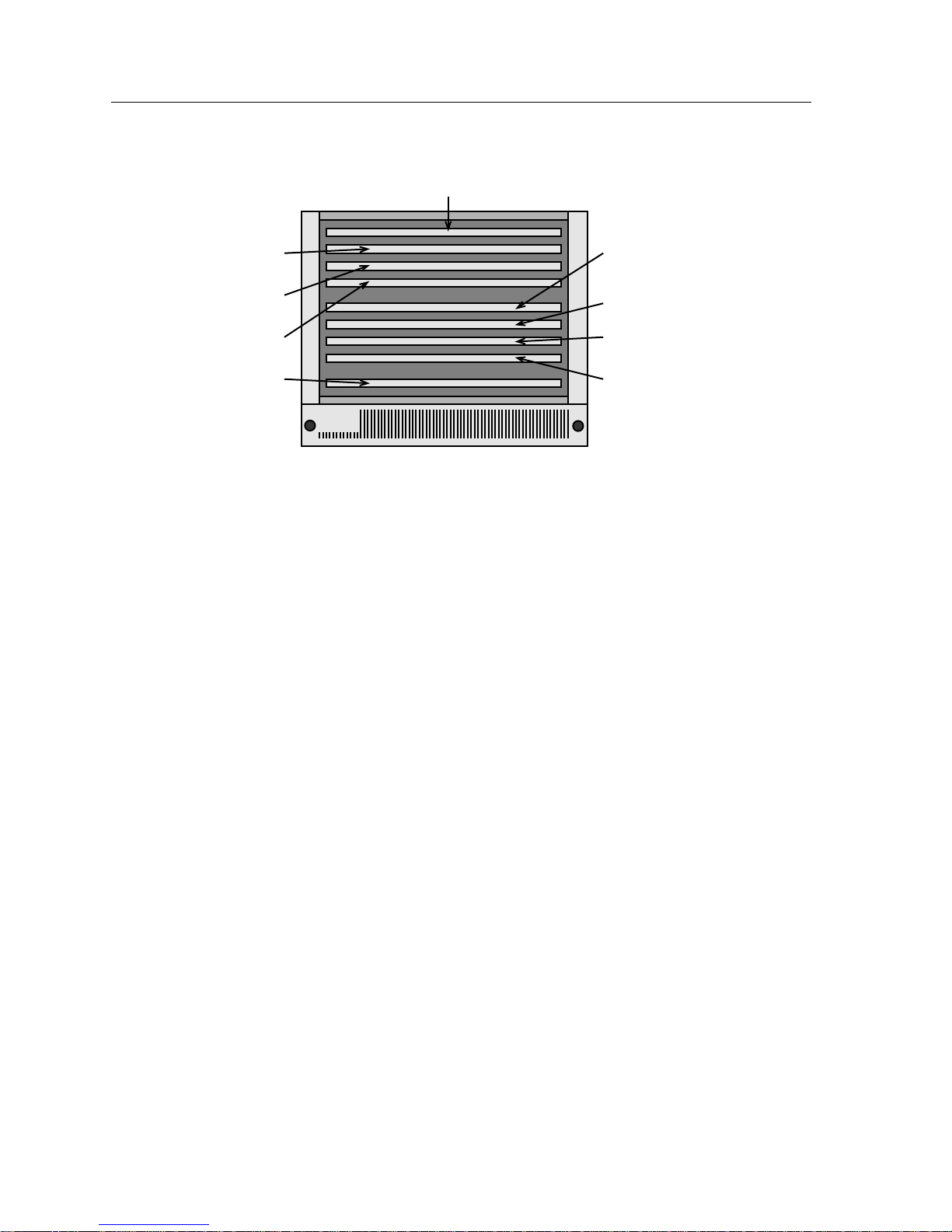
Network Design
Power & Management
Ethernet A
Ethernet B
Ethernet C
FDDI
To reduce the costs of chassis failure, Cabletron has designed the MMAC chassis
to be as modular as possible. Networking modules, power supplies, the cooling
system, any device that the chassis requires for proper operation, is modular in
design, and can be removed and replaced with a minimum of effort and in a very
short amount of time. The best way to recover from a fault is not to have the fault
occur, however. Cabletron Systems has designed the MMAC chassis to be fault
tolerant.
The passive backplane architecture of the MMAC chassis is a prime example of
this design philosophy. The backplane of a modular chassis is its heart. It is the
single point at which all modules in that chassis communicate, receive power, and
are managed by the chassis. If the backplane of the chassis fails, every module in
that chassis that is connected to the backplane fails as well. To avoid these fatal
failures, Cabletron Systems’ MMAC backplane incorporates absolutely no active
electronic components. There are no resistors or capacitors that could critically fail
on the MMAC backplane. All of the active electronics required for the proper
functioning of the MMAC backplane are built onto the chassis modules
themselves. In the event of a failure of one of these components, the replacement
of the failed module allows the network to be rapidly returned to operation.
Token Ring R1
Token Ring R2
Token Ring R3
Token Ring R4
1706n19
Figure 4-9. Flexible Network Bus Channels
4-28 Designing with the MMAC
Page 79
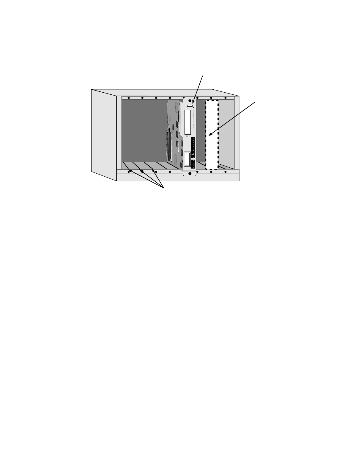
MMAC-M8FNB
SN
ETHERNET
RESET
CPU
RJ45
PRT1
CH A
XMT
1
RCV
XMT
2
RCV
XMT
3
RCV
XMT
4
RCV
XMT
5
RCV
XMT
6
RCV
1
2
3
4
5
C
O
M
1
C
O
M
2
Network Design
Module
Module "slot"
Power Redundancy
Fault-tolerance is also necessary in the supply of electrical power to the modular
chassis. The chassis supplies all modules with electricity. The supply of power in
the correct amperages and voltages for the modules in the chassis is performed by
modular power supplies. As power supplies have high demands placed upon
them by their operation, they are perhaps more susceptible to failure than other
components. Since they are also a key system of the chassis, the loss of a power
supply can mean a catastrophic chassis failure in the same way that a backplane
failure could. To reduce the danger of this occurrence, Cabletron Systems’ larger
MMAC chassis, the MMAC-M5FNB and MMAC-M8FNB, allow for the
configuration of redundant, load-sharing power supplies.
The use of the redundant power supplies gives additional tolerance to the system.
Simple redundancy means that two power supplies are available to the modules
in the chassis. One acts as the primary power supply, while the other remains in
standby. In the event that the primary power supply fails, the secondary power
supply senses its failure and takes over. While this is a valuable feature, it is a
flawed treatment of the problem. If the primary power supply is active while the
secondary is inactive, there is no way of knowing that the secondary power
supply is indeed functional. It also creates a short but significant length of time
that the chassis is without power between the failure of the primary power
supply and the warm-up and activation of the secondary power supply.
Module Guide Channels
Figure 4-10. Chassis, Slots, and Modules
1706n20
Designing with the MMAC 4-29
Page 80

Network Design
Cabletron Systems’ treatment of this issue is the utilization of load-sharing
capabilities in the power supplies. Load-sharing power supplies examine the
chassis they are in, and if they detect another power supply operating in the
chassis, they each supply half of the power requirements of that chassis. In this
way, both supplies are operating at all times at less than half capacity. In the event
that one power supply fails, the other senses the failure and “ramps up” to full
capacity, providing power to the chassis without requiring switchover time.
All of the designs that follow utilize the MMAC-FNB chassis exclusively. While
some external standalone products may be mentioned in the course of describing
a design, this Networking Guide only examines the use of the MMAC chassis in
network designs. As the MMAC chassis cannot operate without power being
supplied to it, all MMAC chassis designs must incorporate at least one power
supply module designed for that capacity MMAC chassis.
NOTE
Every MMAC chassis is shipped configured with some
modules:
- All MMAC chassis are shipped with cooling fan trays and slot
covers for empty module slots.
- The MMAC-M3FNB is shipped with the above as well as one
modular power supply.
4-30 Designing with the MMAC
Page 81

Chapter 5
Ethernet
This chapter examines the Ethernet network technology in detail and provides step-by-step design
instructions for the creation of Ethernet networks using Cabletron Systems networking products.
Description
Ethernet is what is called a contention-based network technology that provides
for a maximum of 10 megabits per second (Mbps) of throughput under ideal
conditions. In order to understand how Ethernet devices work, it is first necessary
to get a basic understanding of how Ethernet networks as a whole operate.
CSMA/CD
Ethernet is based on a network access scheme called Carrier Sense Multiple
Access with Collision Detection. This scheme is abbreviated as CSMA/CD. Before
we examine what CSMA/CD means to us as designers of networks, let’s take a
look at the foundations of Ethernet.
Ethernet is one of the elders of networking, dating back to when the primary
networking cabling was coaxial cable. When an Ethernet station had a packet to
transmit, it would do so, no permission needed. When a packet was sent, it was
transmitted onto the coaxial cable, where it would spread in either direction.
Stations attached to the cable would all receive the signal and determine if it was
intended for them. The basics of Ethernet communication: transmissions go to all
stations on the network, and any station may transmit at any time. This is the MA,
or Multiple Access portion of the CSMA/CD technology.
5-1
Page 82

Ethernet
If the technology was left at that, it is easy to see that it would not function with
more than one station on the network not a very efficient networking solution. If
two stations, which can transmit without requiring permission, both transmitted
different packets at the same time, the electrical impulses that make up their
signals would get combined into a long string of gibberish. The more stations you
added, and the more they needed to communicate, the less the number of
non-mangled packets on the network.
Rather than having each station take a pre-determined turn transmitting, the first
part of CSMA/CD, Carrier Sense, was incorporated. Carrier Sense is the method
by which a station takes a look at the cable to which it is attached. If the cable is
being used, the station will wait and try again later. If the cable is without signals,
the station will transmit. By using Carrier Sense, Ethernet stations greatly reduce
the number of collisions a network experiences.
ACDB
Station C examines network for
availability. No signals noted.
ACDB
ACDB
Figure 5-1. CSMA/CD Operation
In Figure 5-1, above, stations B and D receiv e the tr ansmission
NOTE
before station A. This is due to the fact that signals in a cable or
media travel through that media at an appreciable fraction of
the speed of light. The differences in reception time are called
propagation delay.
Station C transmits. Stations B and
D receive transmission.
Station C monitors network for
error signals. Stations B and D
discard transmission. Station A
receives transmission.
1706n21
5-2 Description
Page 83

Ethernet
Still, two stations may both listen to the line at the same time, and both transmit a
short time after, causing a collision. That is where the CD portion of CSMA/CD
comes into play. Collision Detection means that if a station transmits and causes a
collision, it will notice that a collision has occurred. When this happens, the
transmitting stations that were involved in the collision back off for a random
amount of time, then begin all over again from the Carrier Sense stage with the
same packets.
ACDB
Stations A and C examine
network for availability. No
signals noted.
ACDB
Both stations A and C transmit.
Collision occurs, creating
collision signal.
collision
ACDB
Detecting collision, stations A
and C wait a random amount
of time before attempting
retransmission.
1706n22
Figure 5-2. Collision Detection
Although all of these portions of CSMA/CD are important to network design, the
most important feature for now is the propagation of signals to every point on the
network. It is important to remember that every point on an Ethernet network is
connected to every other point on that Ethernet network. There are some devices
that allow us to break large networks up into smaller ones, or extend networks to
new Ethernets, but we deal with those later.
Description 5-3
Page 84

Ethernet
Media
While Ethernet was originally designed to utilize coaxial cable, the vast majority
of newly designed Ethernet networks operate over Unshielded Twisted Pair
(UTP) cabling. Fiber optics runs a distant second, followed by the two types of
coaxial cable, thick and thin.
The distance limitations to each media type are as follows:
Table 5-1. Ethernet Distance Limitations
Media Max Distance
Thick Coaxial Cable 500 m
Thin Coaxial Cable 185 m
UTP 100 m
Fiber Optics (Multimode) 1000 m
Fiber Optics (Single Mode) 1000 m
These distances are decided by the IEEE, a standards-making body which has
created boundaries within which networks may be designed. This set of rules and
boundaries is called the IEEE 802.3 standard.
Connectivity/Transceivers
Workstations and computers require intermediaries to allow them to connect to
an Ethernet network. The purpose of these intermediary devices is to translate the
electrical signals of the workstation into the electrical signals utilized by the
Ethernet network and its selected media and vice versa. Since these devices allow
the workstations and network to TRANSmit and reCEIVE information, they are
called Transceivers.
The basic function of a transceiver is the conversion of Ethernet signals from a
Male AUI port to another type of media. Media adapters, which are related to
transceivers, are also available. Where a transceiver only converts signals to or
from Male AUI ports, media adapters convert from any standard media to
another standard media. There are media adapters that convert the signals used
on UTP cabling to the pulses of light utilized on fiber optic cabling, and there are
transceiver-like devices that convert the signals of external media (such as UTP or
coaxial cable) into signals used by the Ethernet bus of a chassis. As these adapting
devices allow workstations and devices to connect to the overall Ethernet
network, they are often referred to as Connectivity devices.
5-4 Description
Page 85

The job of a transceiver in chassis design is to provide a connection to a network
that has already been established. Once a network has an established repeater in
the chassis, the addition of chassis modules which allow Ethernet workstations to
connect to the chassis may begin. These connectivity modules may be added to
the chassis until the chassis has no more available module slots remaining or until
the single network has reached the theoretical maximum population for an
Ethernet network, 1,024 stations.
Cabletron Systems connectivity modules are denoted by the suffix MIM, which
stands for Media Interface Module. The MIM provides an interface between the
backplane of the chassis and the external media for which it is intended. The
name of each individual MIM also identifies the external media to which it is
intended to connect. For example, MIMs which are intended to provide a
backplane connection for Unshielded Twisted Pair media are called TPMIMs, for
Twisted Pair Media Interface Module. Those MIMs which provide connections to
fiber optic cabling are called FOMIMs, for Fiber Optic Media Interface Module.
The Example configurations section of this document provides detailed tables
listing the product names, media connectivity, and connector style of each MIM.
Rules and Regulations
Ethernet
Ethernet has a large number of rules associated with it. There are the distance
rules, for one, and the maximum population, for another. The maximum
population (number of devices) on a single Ethernet network is 1,024. Usually,
long before we reach 1,024 devices, we have moved to a new Ethernet network.
How we do that is covered later.
Another maximum associated with Ethernet deals with the maximum number of
devices per segment of cabling. The original Ethernet media, thick and thin
coaxial cable, may each be tapped at multiple points to provide connections for
stations. Each tap must be a certain minimum distance away from other taps, to
keep them from interfering with each other.
And there are more rules. Each cable has a maximum number of places where it
may support a connection. Thick coaxial cable, for example, may have no more
than 100 taps. Thin coaxial cable, which is not shielded against interference as
well as thick coaxial cable, may have no more than 30 taps. UTP and fiber optics
have no taps, stations must be connected at each end of the cable.
But what about the 1,024 maximum number of devices? If the absolute maximum
you can have on any of these media is 100 (over thick coaxial cable), how can you
ever get to the maximum number? And, along the same lines, what use is a UTP
link if you can only network two devices? A total of two stations does not seem
like a very efficient LAN.
Description 5-5
Page 86

Ethernet
Repeating
When Ethernet was created, the general philosophy was “one cable, one LAN.”
Signals would be transmitted to every point on a single cable. This transmission
means is fine for the multipoint media, like thick and thin coaxial cable, but is
useless on a media that you cannot tap into, like fiber optics or UTP. Also,
networks were very limited by distance and the maximum number of stations, as
we have seen. In order to extend Ethernet networks, devices called repeaters were
developed.
Repeaters take in an Ethernet signal from one connection and send it out to the
other stations connected to that repeater. The earliest repeaters were used to
connect one length of coaxial cable to a second length of coaxial cable, so you
could, for example, use two lengths of thick coaxial cable to reach a maximum
end-to-end distance of 1000 meters with a maximum of 200 stations on the
network. Later repeaters allowed you to attach multiple segments together. These
repeaters are known, logically enough, as multiport repeaters. This changed the
Ethernet general philosophy from “one cable, one LAN” to “many cables, one
LAN.”
Since it was not always desirable to have thick coaxial cable running through all
your offices, repeaters took the logical step of repeating Ethernet signals to
different media. These repeaters could be useful for connecting a network of thick
coaxial cable to a network of thin coaxial cable or a section of fiber optics.
Eventually, these repeaters began to connect large numbers of thin coaxial cables,
used commonly in offices and laboratories, to tap points on thick coaxial cables
known as “backbones,” which provided interconnection for the repeaters and
were usually kept out of sight in cabling conduits. These multiport repeaters were
the forebears of today’s intelligent hubs.
Repeaters/Hubs
Repeaters are one of the building blocks of Ethernet, and are the foundation upon
which all Ethernet hubs are based. In its simplest form, a hub, populated with
modules, is basically a huge multiport repeater. While additional functions such
as bridging and routing may be added, the basic job of a hub is to repeat signals
coming in through one port to all the other ports in the hub. By placing a repeater
in a modular chassis, you allow the chassis to accept and utilize connectivity
modules.
The number of repeaters a given configuration needs depends entirely on the
number of Ethernet networks that are being created. For a configuration
providing only one Ethernet network, only one device supplying the repeater
functionality for that network is required. It is the job of this repeater to support
any Media Interface Modules (above) that are configured to operate on its
network. Theoretically, one repeater module could support any number of MIMs
providing up to the theoretical maximum number of Ethernet station connections,
1,024. In reality, the modular intelligent chassis will likely be filled to capacity
with MIMs before that maximum is reached, requiring that the expansion of the
network be made through the use of a second modular chassis.
5-6 Description
Page 87

Ethernet
For each new chassis that is to support an Ethernet network through the use of
MIMs, repeating must be supplied anew. So, if one network had outgrown its
chassis and was being extended by way of a connection to a second modular
chassis, repeating would have to be supplied all over again to allow the addition
of new MIMs to the second chassis.
Cabletron’s basic repeater module is the IRM, or Intelligent Repeater Module,
series. The IRM series of management modules provides repeating for a single
Ethernet network within the MMAC chassis and also provides management
functions for that network. Other modules which provide repeating functions
that support the configuration of MIMs in the chassis include the EMME and
EMM-E6 Ethernet modules. A chassis which is intended to contain a single
Ethernet network, therefore, would be configured first with some IRM series
module or EMME module to provide repeating. This would create the Ethernet
network, to which MIMs would be added to supply connectivity.
By the same token, if multiple Ethernet networks are to be configured in a single
MMAC chassis, each separate Ethernet network must receive repeating functions
for it to operate. All of the Cabletron Systems IRM modules provide Ethernet
repeating for one Ethernet network only, however. Since Cabletron Systems’
MMAC chassis has the capability to support up to three Ethernet networks
(Ethernet channels A, B, and C) across the single chassis backplane, how do we
provide repeating functions to the second and third networks?
The answer lies in the use of combined function modules. Rather than requiring
that a chassis supporting multiple networks consists of a repeater for one network
and its associated MIM modules, then a repeater for a second network, followed
by its MIM modules, followed by the third repeater and its MIM modules,
Cabletron Systems combined the functions of a Media Interface Module with
those of a repeater to create MIMs that perform their own repeating. These
Repeating Media Interface Modules, or RMIMs, are made specifically for
connection to the B and C Channels of the MMAC chassis backplane. Since the
repeater functionality for these additional networks is included in the RMIMs
themselves, no additional IRM-style modules are required for the functioning of
multiple Ethernets in the chassis.
For example, to create two networks in an MMAC chassis, a module would be
required to provide repeating for the MIM modules of the first Ethernet, then
RMIM modules, which connect to the second Ethernet, are added to the chassis.
As these modules supply their own repeating functions for the second Ethernet
network, the RMIM modules are able to function without an additional dedicated
repeater.
Any MIM which supports a connection to the Ethernet B or C Channels of the
MMAC chassis will provide the repeater functionality for those connections. The
Ethernet Port Assignment modules, or TPXMIMs, allow ports to be connected to
the A, B, or C Channels of the MMAC chassis. The TPXMIM, like the Repeating
Media Interface Module, includes repeater functions for the B and C channels of
the chassis, and will require the functions of an IRM, EMME, or other A Channel
repeater to be able to assign ports to the A Channel Ethernet network.
Description 5-7
Page 88

Ethernet
Repeater Rules
Naturally, there are rules surrounding repeaters, just as there are rules
surrounding cabling. A set of guidelines known collectively as the repeater rule
make plain the maximum limits of repeaters. The rule is based on the numbers
5-4-3.
5: Maximum of five (5) Ethernet segments. No more than five repeated
Ethernet segments may be connected in the longest repeater path. This could
be five segments of thick coaxial cable, three fiber optic and two thin coaxial
cables, five interconnected hubs, etc. The way to look for a violation of the 5
rule is to go through your design marking any segments that are connected to
repeaters. Then follow those to determine the longest possible path that data
would have to travel. If your design has any paths crossing more than five
network segments, you have broken the first of the repeater rules.
4: Maximum of four (4) repeater hops. Each time a signal passes through a
device that performs repeating, be it a standalone repeater or a hub module,
you add one “repeater hop”. To check for 4 rule violations, figure out the path
that passes through the largest number of repeaters. If a signal from one end
to the other must pass through more than four repeaters, the design breaks
the rule.
Arrow shows path of signal
"Repeater Hop"
Repeater
Network A
Network B
1706n23
Figure 5-3. Repeater Hop
3: The three (3) rule specifies the number of segments connected by repeaters
that may have more than two stations on them. If you have three segments
connected by repeaters, they may all have users. If, however, you have four
segments connected by repeaters, only three of them may have user stations
on them, beyond the connections to the repeaters between them. Note that
device other than the repeaters on either end of the path classifies as a
any
station for this rule, not just workstations.
The example in Figure 5-4 shows a proposed Ethernet network being examined
for repeater rule violations. The first step is identifying the longest signal path. A
quick count of repeater hops indicates that the longest signal path travels through
R1, R2, R4, R5, and R6. With six Ethernet segments in the longest signal path, this
network is already out of specifications, violating the “5” rule.
5-8 Description
Page 89
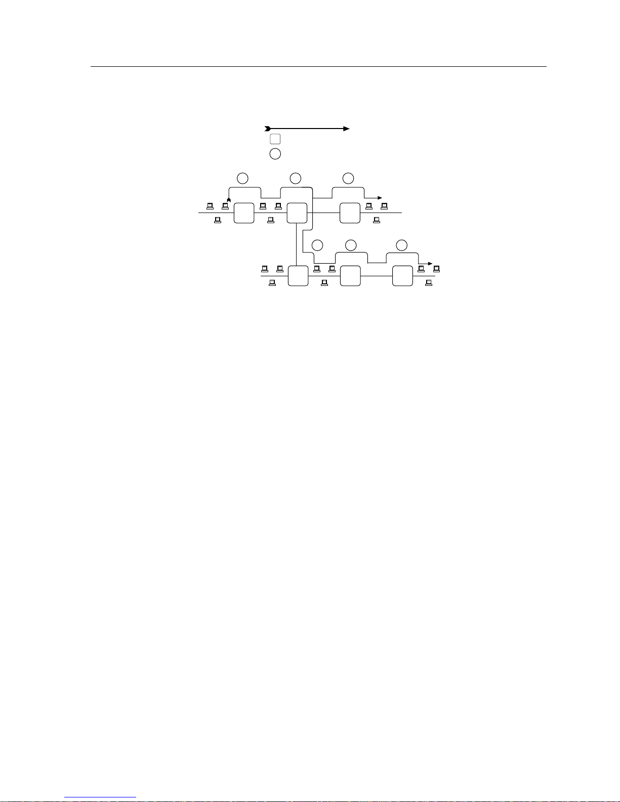
Arrow shows path of signal
R1
Repeater
Repeater Hop
3
Ethernet
1
R1 R2 R3
2
3
R4 R5 R6
3
4
5
1706n24
Figure 5-4. Repeater Rule Violation
Furthermore, the number of repeater hops in the longest signal path is five, one in
excess of the four allowed by the repeater rule. The network shown in Figure 5-4
would not function properly, due to the errors introduced by the violations of the
repeater rule. This network will have to be redesigned using some form of
segmentation (see Segmentation, Chapter 3, or refer to the Segmented Ethernet
section later in this chapter).
Description 5-9
Page 90

Ethernet
Simple Ethernet Configuration
The term “simple” in this definition is used to indicate that the network is
configured as a single repeated network and does not incorporate any bridging,
routing, switching or other segmentation between stations. All of the Ethernet
stations in a simple Ethernet network are treated as if they were stations located
on one segment of coaxial cable.
Design Philosophy
A simple Ethernet operates on the basic principles of IEEE 802.3 LANs: a
transmission by any station on the network is received by every other station, and
may transmit at any time that the station senses that the common media (in this
case, the modular chassis) is not being utilized.
The simple Ethernet network design is a relatively inexpensive means of
networking a limited number of workstations that do not have particularly
demanding network availability needs. A small company or educational facility
with anywhere from 20 to 180 workstations could utilize a simple Ethernet
configuration such as the one described below.
Design Example
This design provides Ethernet networking services for three departments within a
small personal accounting firm with 63 workstations. Two of these workstations
are dedicated fileservers and one provides access to a tape drive system used for
backups. The cabling used for connections from the workstations to the central
network chassis is Category 5 UTP, which is terminated with standard RJ45 patch
panels and wallplates.
Since the vast majority of applications and uses for the network are not
particularly time- intensive at this location, the cost savings provided by using the
simple Ethernet configuration is considered to outweigh the functionality and
additional performance that could be gained by utilizing other network
technologies and methods. The foundation of this network is a Cabletron Systems
MMAC-M8FNB modular networking chassis, outfitted with the correct modular
power supplies (M8PSM-E). This provides the basic concentrator capability into
which the connectivity and functionality modules are to be added.
Select Chassis
5-10 Simple Ethernet Configuration
Page 91
Ethernet
To provide the starting point for building the Ethernet network, a repeater
module must be placed in the chassis. This module will provide repeating
functions for the Ethernet modules in the chassis that are configured to use the
Ethernet channel A of the backplane. In addition, all of Cabletron Systems’
Ethernet channel A repeaters provide management functions for the modules in
the chassis. To provide Ethernet repeating and supply SNMP management
capabilities, this network will utilize an IRM3 module. The IRM3 repeats any
Ethernet signals that are transmitted by stations on the A Channel of the MMAC
chassis.
Select Chassis
no
Multi-segment?
yes
IRM Family
To provide user connections, the MMAC chassis needs to utilize transceiver or
“connectivity” modules, commonly called Media Interface Modules, or MIMs, as
they provide the physical interface between the MMAC backplane and the
cabling media that connect to the end-user stations.
IRM Family
Select MIMs
Simple Ethernet Configuration 5-11
Page 92

Ethernet
This location utilizes UTP cabling with RJ45 connectors, narrowing the choices of
modules to the TPMIM-22 and TPMIM-24. Since there are 63 stations to provide
connections for, the chassis utilizes three TPMIM-24 Ethernet Media Interface
Modules, supplying a total of 72 RJ45 connectors. The chassis that we are using to
network this facility now looks like Figure 5-5:
1706n25
Figure 5-5. Example Ethernet Configuration 1
The networking device families used in this network design are the Ethernet
repeater and the Ethernet transceiver/Connectivity module. Since there are
several different products manufactured by Cabletron Systems which meet these
networking device families, the actual configuration of the network can be altered
by substituting different products of these families in the modular networking
chassis. The product families and their individual members are listed in the series
of tables that follow:
5-12 Simple Ethernet Configuration
Page 93

Modular Intelligent Chassis
The modular intelligent chassis provides the basic platform into which
management and networking modules are inserted. It provides the physical
interconnection of modules through the backplane bus. It is important to note that
modular power supplies are required for the operation of the hub and the
modules within it. The power supply for the MMAC-M3FNB is included with the
purchase of the chassis. The MMAC-M5FNB and MMAC-M8FNB may both be
configured with one or two power supplies which are purchased separately. The
use of two power supplies provides redundant power capability, allowing one
power supply to satisfy the power needs of the hub in the event of a power
supply failure. See the Cabletron Systems Networking Solutions Catalog for detailed
information on available power supplies.
Ethernet
Table 5-2. MMAC Chassis
Product Capacity
MMAC-M3FNB 1 Half Slot 2 Full Slots
MMAC-M5FNB 1 Half Slot 4 Full Slots
MMAC-M8FNB 1 Half Slot 7 Full Slots
a. Capacity is additive; Each chassis has the listed number of full slots
in addition to the single, dedicated half-slot utilized by management
modules (i.e: the MMAC-M5FNB has a total of 5 module slots).
Ethernet Repeater and Management Module
The Ethernet repeater and management supplies the IEEE 802.3 repeating
functions which make it possible for individual connections to share the
backplane as a common connection medium. One repeater module is necessary
for the operation of the Ethernet modules.
Table 5-3. Ethernet Repeaters
Required Functions Compliant Modules
“A” Channel Ethernet Repeating and
Management Functions Only
“A” Channel Ethernet Repeating, Extended
Management, and Bridging or Routing to B, C,
and External Ethernet Channels
a
IRM3
EMME/EMM-E6
a
a. The EMM-E6 utilizes the rightmost two slots in the MMAC chassis, the Management Module slot
and one adjacent full Media Interface Module slot.
Simple Ethernet Configuration 5-13
Page 94

Ethernet
Media Interface Modules
To provide connections for the physical cabling, Media Interface Modules are
needed. The number of Media Interface Modules the network must utilize is
dependent upon the number of stations to be connected to the network. Before
selecting modules you must identify the type of physical cabling media and the
connector type to be utilized.
Consult the table below to determine which modules may be used to connect to
the physical cabling plant and calculate the number and exact type of modules
that will be required to fulfill the needs of the network.
Table 5-4. Ethernet MIMs
Media Type Connector Type
AUI (to
DB15 (female) 8 1 MT8-MIM
Number of
Connectors
Max # of
Stations/Connector
Product Name
transceivers)
Thin Coaxial
RG58 12 29 THN-MIM
Cable
UTP RJ45 12 1 TPMIM-22
24 1 TPMIM-24
RJ21 (Telco) 1 12 TPMIM-32
212 TPMIM-34
Multimode
Fiber Optics
Sub-Miniature
Assembly
a
6
1 FOMIM-16
12 1 FOMIM-12
18 1 FOMIM-18
Straight-Tip 6
a
1 FOMIM-26
12 1 FOMIM-22
18 1 FOMIM-28
Single Mode
Straight-Tip 6
a
1 FOMIM-36
Fiber Optics
12 1 FOMIM-32
UTP/STP DB9 12 1 TPMIM-T1
a. Note: All Fiber Optic MIMs provide tw o connectors (transmit and receive) for each Ethernet connection. Number
of connectors given is the maximum number of transmit and receive pairs
5-14 Simple Ethernet Configuration
18 1 FOMIM-38
available on the module.
Page 95

Ethernet
As all of the modules listed in Table 5-4, above, are Ethernet Channel A modules,
they are fully interchangeable in configuration terms. A configuration like the
example given previously could have utilized three TPMIM-34 modules if RJ21
connectors were to be used, or included one FOMIM-26 to connect six stations
with fiber optic cabling.
Even though many simple Ethernets will occupy only one MMAC chassis, it is
important to recognize that any links made from one simple Ethernet chassis to
another that is not made through a bridge or router will expand the one network.
Without the bridge or router present to perform the filtering or forwarding
services for traffic between the two chassis, the modules and stations will act as
though they were configured in a single MMAC. Although the two chassis and
their associated modules are operating on the same network, each modular
chassis to be configured in simple Ethernet fashion requires an Ethernet repeater
module. Without the module, the stations attached to the connectivity modules
will not be able to transmit and receive signals to and from the network.
To illustrate, if a location required two MMAC chassis configured as in the
previous example, connected to one another through a fiber optic connection, we
would begin by placing an IRM3 in each of the MMAC chassis. These IRM3
modules would provide the necessary Ethernet repeating functions to allow the
connectivity modules, TPMIM-24s once again, to operate and communicate with
one another. The fiber optic link between the two hubs (assuming multimode
fiber optics and ST connectors) would be made using the fiber optic connectors on
the front panel of each IRM3. While the stations connected to the TPMIM modules
of each hub would be located in physically distinct areas, the network would treat
all the stations as being on the same logical network, sharing the same 10 Mbps of
bandwidth available in an Ethernet network.
Segmentation
Segmentation is the incorporation of bridging or routing between individual
networks or segments. The segmentation of a network is something that must be
approached cautiously, and extended discussions of this planning are presented
in Chapter 4, Network Design. One of the important design guidelines for
segmentation is to try and follow the 80/20 rule. You want, ideally, to keep 80% of
your traffic local and pass about 20% of your traffic across segmentation devices.
It makes perfect sense, therefore, to put departments that share fileservers on the
same segment. That way users needing access to the file server in question do not
have to cross the bridge, cutting into the speed of the bridge and reducing the
speed of network operations.
This segmentation is based on the extent to which distinct groups of users or
departments are related and require transmission of information betweenone
another. For example, the Payroll, Personnel, and Accounting departments of
most businesses transfer information on a very regular basis. It makes sense from
a network design perspective, therefore, to attempt to keep these departments
from having to pass more than 20% of their traffic across a bridge or other
segmentation device.
Segmentation 5-15
Page 96

Ethernet
Bridges
We may also segment the network logically by geographic location. This makes it
easier to troubleshoot and expand existing networks. Geographic segmentation is
usually an inferior segmentation solution in comparison with segmentation by
related function or access. The increase in logical layout that can be accomplished
using this method is frequently overshadowed by decreased network
performance as a higher percentage of traffic is sent through bridges.
Now that you have learned the basics of single-level repeated Ethernet, we can
progress to the next level of expertise, Bridged Ethernet. Bridges are network
“traffic control” devices which affect the way that information moves from one
network to another. Bridges segment networks, while still allowing traffic that
needs to pass between two networks to pass. By doing this, bridges keep traffic
local, freeing a bridged network from the effects of traffic on its distant neighbors.
A bridge connects networks in a similar fashion to a repeater, but a bridge goes a
few steps further, monitoring the individual data packets to determine if they
need to be sent to other segments or not, and regenerating, retiming, and
reclocking the signal to increase its ability to be retransmitted.
A bridge is a device that can be added to a network to allow expansion beyond
the limitations of IEEE 802.3. If an Ethernet network has a repeater hop of four
repeaters or a round trip propagation delay near the 51.2µs maximum, a bridge
can be used to build an extended network. Ethernet bridges read in packets and
decide to filter, discard, or forward based on the destination address of the packet.
The simple forward/filter decision process allows a bridge to segment traffic
between two networks, keeping local traffic local. This process increases the
availability of each network while still allowing traffic destined for the opposite
side of the bridge to pass.
When multiple Ethernet networks are created within a single chassis, they all
operate as separate networks. Although a configuration may support three
Ethernet networks in a single modular chassis, they are considered separate from
one another and do not exchange information. This effectively means that an
Ethernet station on Ethernet Channel A is not able to communicate with an
Ethernet station on Ethernet Channel B in the same chassis.
It is the function of bridges to connect separate networks while maintaining the
separation between them. An Ethernet bridge acts in much the same way as a
bridge in the physical world. It provides a single point of access between both
networks, allowing traffic which must cross to the other network to do so, while
keeping unrelated network activity on one side of the bridge from impacting the
operation of the network on the other side of the bridge.
5-16 Segmentation
Page 97

Ethernet
Network A
Bridge
Network B
1706n26
Figure 5-6. Bridges
The bridge is considered a node on the network and performs store and forward
functions for packets on each network. This contrasts with a repeater which
repeats the signal bit by bit from one side of the network to the other. The bridge
actually reads each packet, checks the packet for accuracy, then decides whether
the packet should be sent to the other network based on the destination address.
If the other network is busy, it is the responsibility of the bridge to store the
packet, for a reasonable time, until the transmission can be made.
The bridge is also responsible for handling collisions. If a collision happens as the
bridge is transmitting onto the second network, the bridge is responsible for the
back off and retransmission process. The original sending node is not made aware
of the collision. It assumes the packet has been sent correctly. If the bridge is
unable to send the packet to its final destination, the original sending station,
expecting some response from the device it was attempting to contact, will “time
out” and may attempt retransmission.
The bridge decides whether to forward or filter a packet based on the physical
location of the destination device with respect to the source device. A bridge
dynamically learns the physical location of devices by logging the source
addresses of each packet and the bridge port the packet was received on in a table
called the Source Address Table (SAT).
Segmentation 5-17
Page 98

Ethernet
Cabletron produces two different types of Ethernet bridges; those that are
configured to operate within the MMAC chassis and those which are standalone
external bridges. Cabletron’s main internal bridge module for Ethernet networks
are the EMME family of repeater/bridge/management modules, the EMME and
EMM-E6. These modules provide bridging functions for the three Ethernet
channels of the MMAC backplane, bridging from these channels to one (in the
case of the EMME) or three (in the case of the EMM-E6) external networks,
repeating functions for Ethernet Channel A, and high-level management of the
modules within the chassis. Any chassis intending to use the Multichannel
Ethernet architecture of the MMAC chassis, therefore, requires the use of an
EMME or EMM-E6 module to supply the repeating and bridging functions
required.
In addition, Ethernet bridges can connect an Ethernet network to another
technology, provided that the networks are similar. Similar technologies only
differ in the lower level network control operations such as the formulation of
packets and the transmission of signals. Since bridges operate at a relatively basic
level, they can perform the translation or encapsulation required to connect two
different technologies such as Ethernet and FDDI, or Ethernet and Token Ring.
Cabletron manufactures several multiple-technology bridges. An example of a
multi-technology bridge is the FDMMIM. The FDMMIM provides FDDI
management for the creation of FDDI rings within an MMAC chassis, as
described in Chapter 7, FDDI. In addition to its FDDI ring control functions, the
FDMMIM is also an Ethernet-to-FDDI bridge. The FDMMIM connects to Ethernet
Channel A of the MMAC backplane and to the FDDI portion of the MMAC’s
FNB. By placing an FDMMIM in a chassis containing Ethernet modules with a
connection to Ethernet Channel A, whether through an IRM repeater or an EMME
bridge, the FDMMIM converts any FDDI frames intended for those Ethernet
modules into Ethernet packets, and converts Ethernet packets from Ethernet
Channel A which are intended for the FDDI ring into FDDI frames.
This bridging functionality is the basis of creating backbones which utilize a
different technology than workgroup networks. The most common backbone
strategy is to interconnect several Ethernet workgroups, which operate at a
maximum of 10 Mbps, to each other with an FDDI backbone, which operates at
100 Mbps. An FDMMIM configured in an Ethernet chassis provides the bridging
functions necessary to allow the chassis to connect to such a backbone.
5-18 Segmentation
Page 99

Ethernet
Ethernet
Ethernet
FDDI Backbone
EthernetEthernet
1706n27
Figure 5-7. FDDI Backbone
Bridge modules which connect an Ethernet network to Token Ring networks or
Wide Area networks, serial terminals, AppleTalk networks, and Systems Network
Architecture (SNA) are also available.
One special case of Ethernet bridging is the use of Bridge/Router Interface
Modules (BRIMs). These are small modules which are placed within another
MMAC module and which can be used to provide a bridged or routed connection
to another network or another similar network technology. Cabletron Systems
produces a number of products which support BRIMs, such as the EMM-E6 and
the ESXMIM Ethernet modules. The BRIM module performs
technology-to-technology interconnection without reducing the flexibility of the
module it is configured in.
For example; an EMM-E6 module could be configured initially without any BRIM
connections. As a facility added more users and another modular chassis to the
corporate network, perhaps a BRIM-E6 could be added to the EMM-E6
management module of the chassis. This Ethernet BRIM would provide one
external bridged Ethernet connection which could be used for the
chassis-to-chassis connection. As the network continued to grow, and more
MMAC chassis were added to the network, the traffic on the chassis-to-chassis
links increased, until it was decided that an FDDI connection between the
separate chassis would help reduce network delays. In this case, the BRIM-E6
modules which had been providing Ethernet to Ethernet bridging in the EMM-E6
module could be exchanged for BRIM-F6 modules, which would supply Ethernet
to FDDI bridging for these chassis.
Segmentation 5-19
Page 100

Ethernet
The table which follows lists the available MMAC chassis modules which
perform bridging between the Ethernet technology and other similar network
technologies.
Bridging: This indicates what technologies the module bridges. In the case of the
ETWMIM, the module is capable of bridging Ethernet to both Token Ring and
Wide Area networks. For this reason, the ETWMIM is treated in two separate
entries in the table.
Ethernet Subscription: This entry refers to the means by which the bridge module
connects to the Ethernet network it is bridging to or from. In some cases, the
bridge may be configured to use one of a series of subscription methods.
Bridged Technology Subscription: This field details where the physical connection
to the non-Ethernet bridged technology is made. Entries indicating connections
made through a BRIM slot, by nature, indicate a front panel connection scheme.
Table 5-5. Multi-Technology Bridges
Module Bridging Ethernet Subscription
FDMMIM/
Ethernet-FDDI Channel A FDDI/FNB
Bridged Technology
Subscription
FDMMIM-04
ETWMIM Ethernet-TR Channel A/External TR/FNB
ETWMIM Ethernet-WAN Channel A/External Front Panel
CSMIM2-T Ethernet-TCP/IP
Channels A/B/C Front Panel
Terminals
CSMIM2-LT Ethernet-TCP/IP and
Channels A/B/C Front Panel
DEC LAT Terminals
GatorSTAR/GX-M Ethernet-AppleTalk Channel A Front Panel
EMM-E6 Ethernet-BRIM Channels A/B/C/D BRIM Slot
ESXMIM/
Ethernet-BRIM Channel A/External BRIM Slot
ESXMIM-F2
SNACMIM/E Ethernet-SNA Channel A Front Panel
Bridging Rules
As with repeaters, there are rules associated with the maximum number of
bridges that may be used on any signal path. With bridges, you may configure an
Ethernet signal path which contains eight (8) segments and seven (7) bridges.
5-20 Segmentation
 Loading...