

Page 1
The Complete Networking Soluti
on
MCC-DFL QUICK REFERENCE
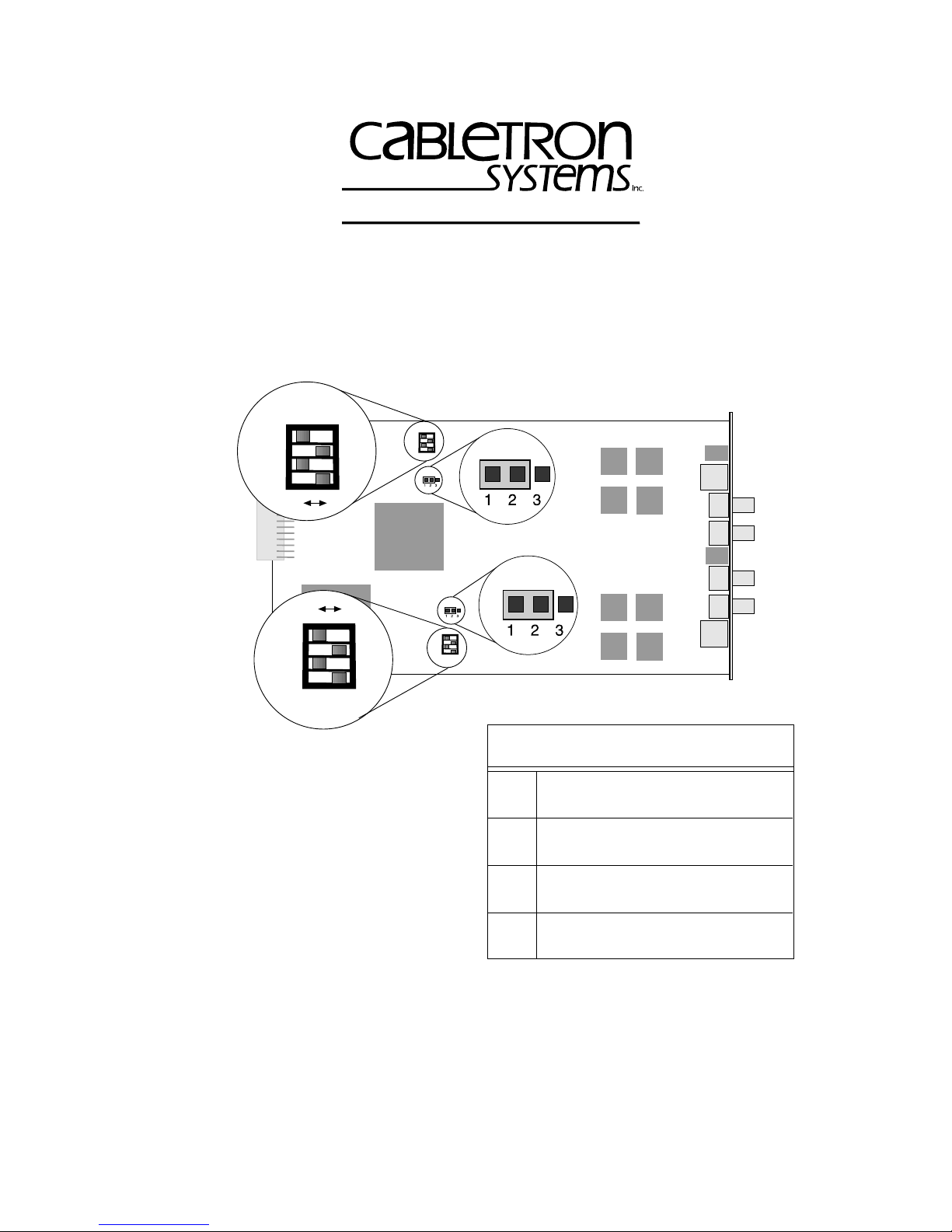
QR.1 SETTING SWITCHES AND JUMPERS
SW1
1234
OFF
OFF
1234
ON
ON
SW1
1234
P1
P2
1234
SW2
P1
P2
SW2
(From back of card)
SW1 (FOT-A or RI)
Switch Configuration Table
SW2 (FOT-B or RO)
Notes: SW1 switchblock manages FOT-A.
SW2 switchblock manages FOT-B.
Individual switches on each
On – Cabletron fiber key
1
Off – 802.5J fiber key
switchblock have the same
functionality.
On – RO or lobe (RJ45 port)
2
Off – RI or station (RJ45 port)
Jumper P1 controls ring speed of
FOT-A.
Jumper P2 controls ring speed of
On – Autowrap enable (RJ45 port)
3
Off – Autowrap disable (RJ45 port)
FOT-B.
On – Station and lobe application
4
Off – RI and RO application
Location of SW1/SW2 Switchblocks And Jumpers P1/P2
(Default Settings)
Copyright 1997 by Cabletron Systems, Inc., P.O. Box 5005, Rochester, NH 03866-5005
All Rights Reserved
Printed in the United States of America
Order Number: 9032131-01 July, 1997
QR-1
Page 2
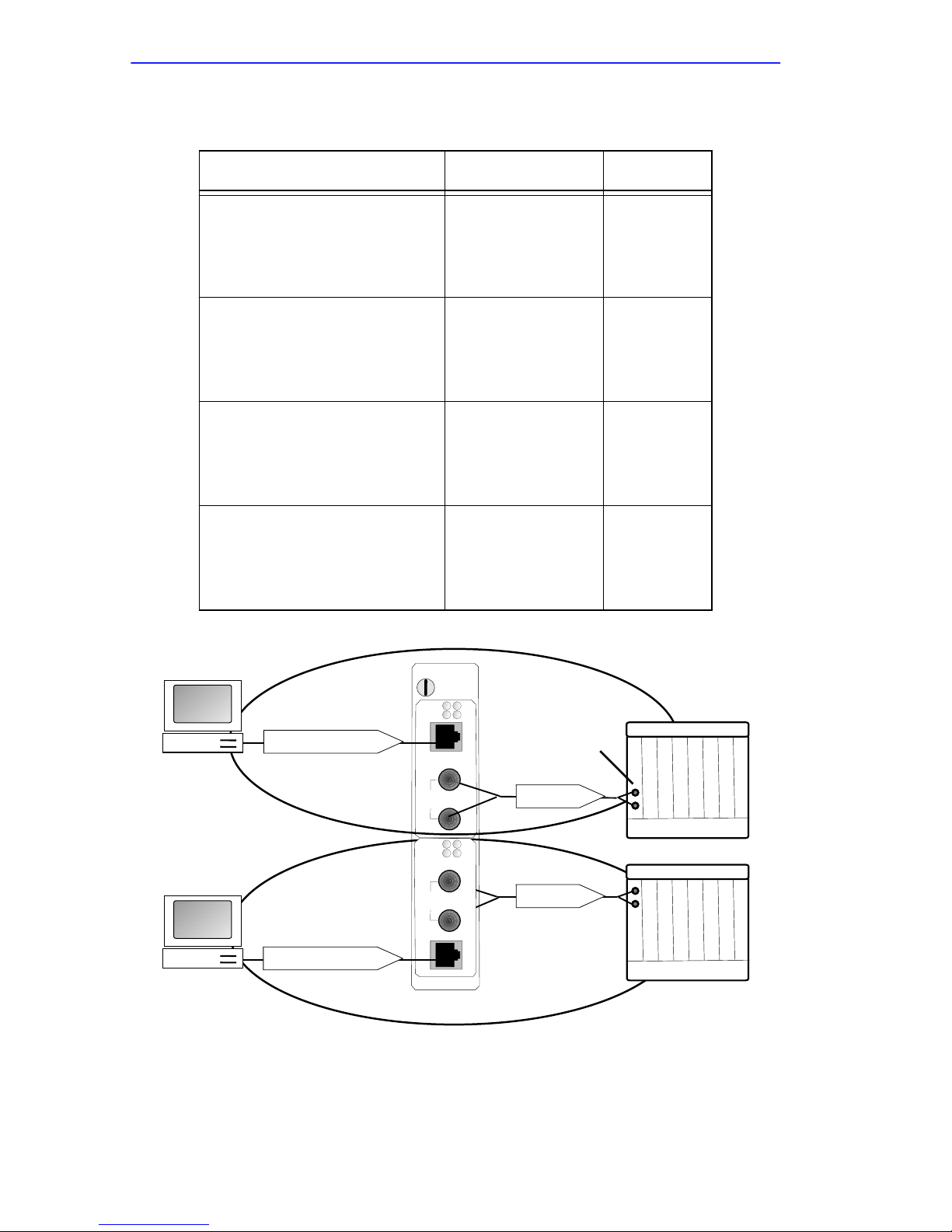
QR.1.1 Selecting Port Configurations
Configuration Switch Settings Example
RJ45 port as a lobe
Fiber ST port as a station
(Default configuration)
RJ45 port as a station
Fiber ST port as a lobe
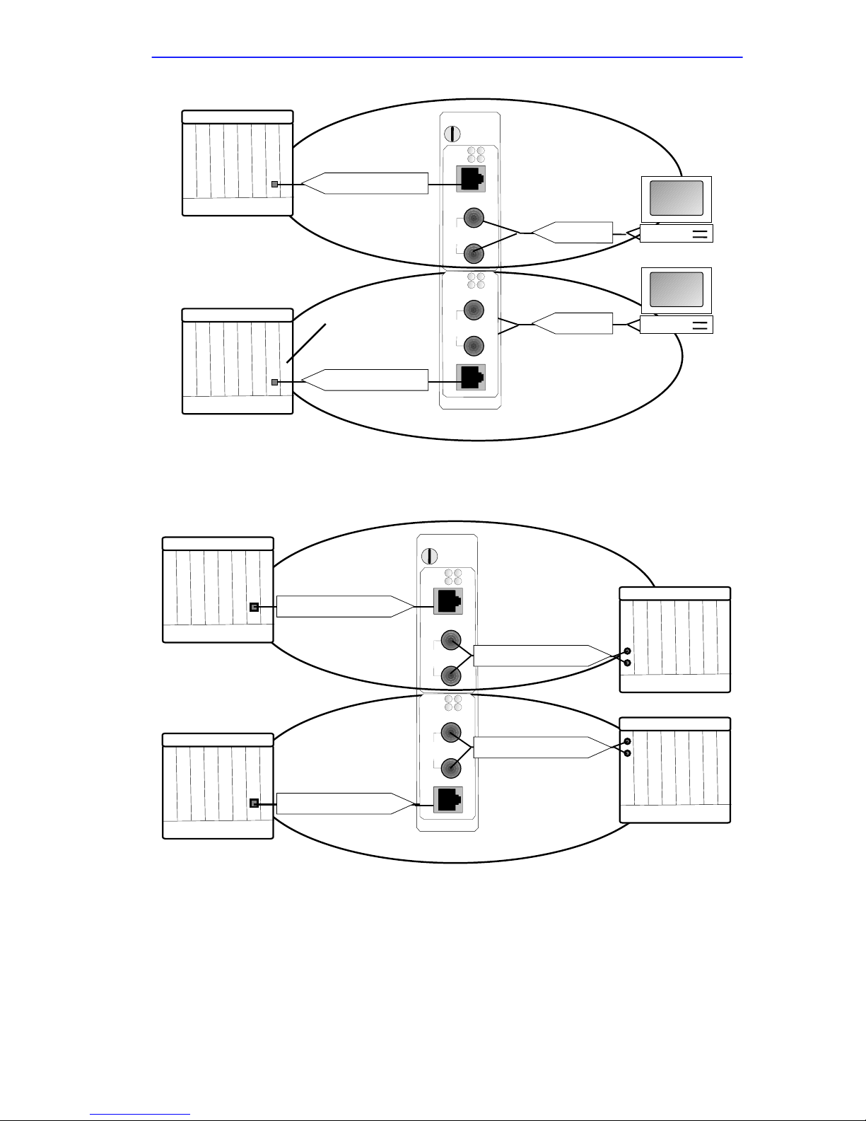
RJ45 port as a RI
Fiber ST port as a RO
RJ45 port as a RO
Fiber ST port as a RI
Station
1 – Off
2 – On
3 – Off
4 – On
1 – Off
2 – Off
3 – Off
4 – On
1 – On or Off
2 – Off
3 – On or Off
4 – Off
1 – On or Off
2 – On
3 – On or Off
4 – Off
MCC-DFL
A
B
C
D
Phantom Current
Phantom Current
P1
PWR
P2
16 Mb
P
1
F
O
TX
T
A
P
2
RX
P1
PWR
P2
16 Mb
TX
P
1
F
O
RX
T
B
P
2
Example A
Concentrator
Fiber Key
Fiber Key
QR-2
Page 3
MMAC
Phantom Current
Concentrator
Phantom Current
Example B
MCC-DFL
PWR
16 Mb
P
1
F
O
T
A
P
2
PWR
16 Mb
P
1
F
O
T
B
P
2
P1
P2
TX
Fiber Key
RX
P1
P2
TX
Station
Fiber Key
RX
MMAC
Ring Out To Ring In
Ring Out To Ring In
MCC-DFL
P1
PWR
P2
16 Mb
P
1
F
O
TX
T
A
P
2
PWR
16 Mb
P
1
F
O
T
B
P
2
Ring Out To Ring In
RX
P1
P2
TX
Ring Out To Ring In
RX
Example C
MMAC
QR-3
Page 4

MMAC
Ring Out To Ring In
Ring Out To Ring In
MCC-DFL
P1
PWR
P2
16 Mb
P
1
F
O
T
A
P
2
PWR
16 Mb
P
1
F
O
T
B
P
2
Ring Out To Ring In
TX
RX
P1
P2
TX
RX
Ring Out To Ring In
Example D
MMAC
QR.1.2 Selecting The Ring Speed(s)
The jumpers P1 and P2 are used to select the MCC-DFL’s ring(s) speed.
Use jumper P1 to set the ring speed of FOT-A, as shown in the table.
Ring Speed of FOT-A Put Jumper P1 Sleeve Over
16 Mbps Pins 1 and 2 (Default setting)
4 Mbps Pins 2 and 3
Use jumper P 2 to set the ring speed of FOT-B, as shown in the table.
Ring Speed of FOT-B Put Jumper P2 Sleeve Over
16 Mbps Pins 1 and 2 (Default setting)
4 Mbps Pins 2 and 3
QR-4
Page 5

QR.1.3 Description Of Switches
Switch 1
You can set the type of fiber keying on RI/RO ports to connect to devices
using 802.5J fiber keying or devices using Cabletron fiber keying.
Switch 1 dictates the type of fiber keying; the setting depends on whether
the attached device is using Cabletron fiber ke ying or 802.5J fiber ke ying.
Set the switch as shown in the table.
Cabletron Systems offers complete compatibility with vendor
NOTE
Keying Type for Fiber RI/RO ST Port * Set Switch 1 to Position
Connection to Cabletron compliant devices On
products that comply with the “new” 802.5J standard for fiber
RI/RO ports. Therefore, the MCC-DFL offers connectivity to
products using 802.5J or Cabletron Systems fiber keying.
Connection to 802.5J compliant devices Off
*Applicable to RI/RO applications only – 802.5J fiber keying is always
used for station and lobe applications.
Switch 2
This switch works in conjunction with Switch 4 to select the mode of
operation for the RJ45 port. Use Switch 4 to dictate whether the FOT will
act as a RI/RO device or station/lobe device. Once this has been done
Switch 2 determines the application of the RJ45 port. The fiber ST port
automatically configures to work with the RJ45 port. For example,
configuring the RJ45 port as a RI, automatically changes the fiber ST port
to a RO. Set Switch 2 as shown in the table.
Mode of Operation for RJ-45 Port Set Switch 2 to Position
RO or lobe applications On
RI or station applications Off
QR-5
Page 6

Switch 3
When the FOT is being used as a RI/RO device this switch enables or
disables the autowrap feature on the RJ45 port. It has no relevance to
station/lobe applications. The feature should be enabled to connect to
Cabletron devices or disabled to connect to non-Cabletron devices.
Set Switch 3 as shown in the table.
Autowrap on RJ45 RI/RO Port Set Switch 3 to Position
Connection to Cabletron devices On
Connection to non-Cabletron devices Off
Switch 4
This switch selects the mode on the entire FOT. Use the switch to
configure it as a RI/RO de vice or a station/lobe device. Then use Switch 2
to establish the configuration of the RJ45 port; the fiber ST port
configures automatically. Set Switch 4 as shown in the table.
Configure FOT Mode for Set Switch 4 to Position
RI/RO applications Off
Station/Lobe applications On
QR-6
Page 7

QR.2 LED FUNCTIONS
Consult the diagram to help interpret LED indications.
MCC-DFL
P1
PWR
P2
16 Mb
P
1
F
O
TX
T
A
P
2
RX
P1
PWR
P2
16 Mb
TX
P
1
F
O
RX
T
B
P
2
PWR
PWR
16 Mb
P1
P216 Mb
P1
P2
MCC-DFL LEDs
PWR - Power
The
PWR
LED lights GREEN during normal operation, indicating the
reception of power. If the LED is off, the MCC-DFL is not receiving
power.
16 Mb - Ring Speed
Each FOT has a
16 Mb
LED. The LEDs lights YELLOW to indicate a
16 Mbps ring speed on the associated FOT. An unlit LED indicates a ring
speed of 4 Mbps on the associated FOT.
P1 And P2 - Ports
Each FOT has P1 and P2 LEDs to indicate the status of the associated
port.
On FOT-A, the P1 LED indicates the status of the RJ45 port and the
P2
LED indicates the status of the fiber ST port.
QR-7
Page 8

On FOT-B, the P1 LED indicates the status of the fiber ST port and the P2
LED indicates the status of the RJ45 port.
The P1 and P2 LEDs act differently on FOTs configured for
NOTE
station/lobe applications than they do for FOTs configured for
RI/RO applications.
P1 And P2 LEDs For Station And Lobe Ports
The P1 and P2 LED indications vary slightly for fiber ST and RJ45 ports.
The table below describes the LED indications for ports configured as
lobe or station ports.
Port LED Activity Meaning
GREEN Phantom current present (port inserted).
RJ45
Lobe or
Station
Fiber
Lobe
Fiber
Station
OFF No phantom current present (port wrapped).
Blinking RED
(Lobe port only)
GREEN Fiber key received (port inserted).
Blinking GREEN
Blinking RED Speed-fault condition caused the port to wrap.
OFF Rx disconnected - signal loss.
GREEN Fiber key received (port inserted).
Blinking GREEN
OFF Rx disconnected - signal loss.
Speed-fault condition caused the port to wrap.
The connection from the upstream device to
the Receive connection is complete but the
port is wrapped.
The connection from the upstream device to
the Receive connection is complete but the
port is wrapped.
QR-8
Page 9

P1 And P2 LEDs For RI And RO Ports
The P1 and P2 LEDs indicate the status of the RI/RO ports as described
in the table.
Port LED Activity Meaning
GREEN Active (port open)
Blinking GREEN Autowrap condition (port wrapped).
RJ45
RI/RO
Fiber
RI/RO
Blinking RED
OFF No activity (port wrapped).
GREEN Rx connected, fiber key received.
Blinking GREEN
Speed-fault condition caused the port to
wrap.
The connection from the upstream device to
the Receive connection is complete but from
the Transmit connection to the downstream
device it is incomplete.
Blinking RED
OFF No connection.
Speed-fault condition caused the port to
wrap.
QR-9
Page 10

QR-10
 Loading...