

Page 1
The Complete Networking Solut
ion
MCC-D2PM QUICK REFERENCE
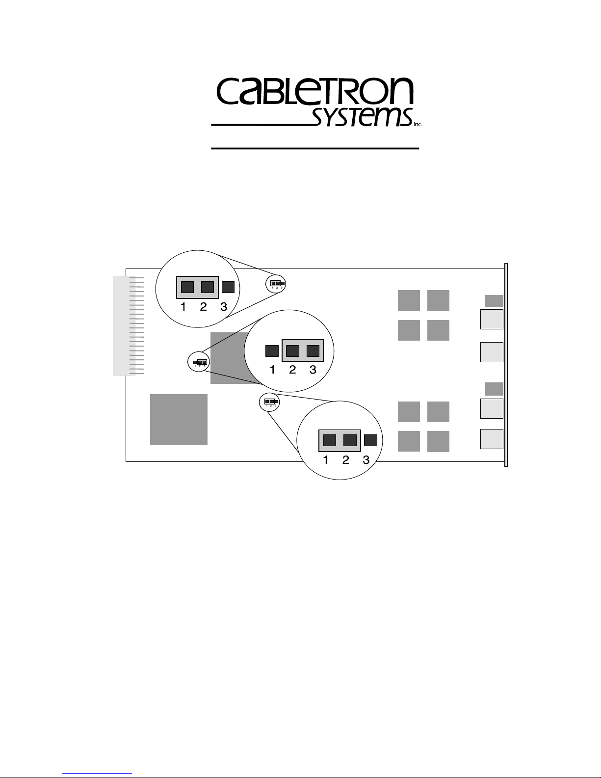
QR.1 SETTING JUMPERS
P1
P1
P3
P3
P2
P2
Location of Jumpers P1, P2, And P3
(Default Settings)
Copyright 1997 by Cabletron Systems, Inc., P.O. Box 5005, Rochester, NH 03866-5005
All Rights Reserved
Printed in the United States of America
Order Number: 9032133-01 July, 1997
QR-1
Page 2

QR.1.1 Joining The MAU Into One Ring
Each MA U can occupy one ring. This allo ws stations connected to the top
pair of lobe ports (labeled P1 and P2) to communicate with stations
connected to the bottom pair of lobe ports (labeled P3 and P4). Enable or
disable this feature using jumper P3, as shown in the following table.
Ring Configuration Put Jumper P3 Sleeve Over
MCC-D2PM split into two rings Pins 2 and 3 (Default setting)
All ports on the same ring Pins 1 and 2
If you split the MAU into two rings, you may need to set the speed of the
second ring.
QR.1.2 Selecting The Ring Speed(s)
Use jumper P1 to select the ring speed of the MCC-D2PM, as shown in
the table.
If the MCC-D2PM is split into two rings, then jumper P1
NOTE
controls the speed of the top two lobe ports (labeled P1
and P2).
Ring Speed Setting Put Jumper P1 Sleeve Over
16 Mbps Pins 1 and 2 (Default setting)
4 Mbps Pins 2 and 3
Use jumper P 2 to set the speed of the bottom ring (labeled P3 and P4)
when the MCC-D2PM has been configured as two MAUs on separate
rings. Otherwise, it is not used (in single ring mode).
Ring Speed Setting Put Jumper P2 Sleeve Over
16 Mbps Pins 1 and 2 (Default setting)
4 Mbps Pins 2 and 3
QR-2
Page 3

QR.1.3 Summary Of Jumper Settings
Only reposition the jumpers listed in the table below. All other
jumpers are set at the factory and should not be repositioned.
Note the position of these jumpers and switches for future
reference.
Jumper Setting
P1
Sleeve over Pins 2 and 3 – 4 Mbps
Sleeve over Pins 1 and 2 – Bottom ring speed 16 Mbps
Sleeve over Pins 1 and 2 – 16 Mbps
P2
P3
Sleeve over Pins 2 and 3 – Bottom ring speed 4 Mbps
Sleeve over Pins 2 and 3 – Ports divided into two rings
Sleeve over Pins 1 and 2 – All ports on the same ring
Note
: Default settings (set at the factory) are in
QR.2 LED FUNCTIONS
Consult the diagram to help interpret LED indications.
MCC-D2PM
P1
P216 Mb
16 Mb
PWR
P
1
P1
P2
PWR
bold
.
P
2
2 RINGS
16 Mb
P
3
P
4
P3
P4
2 RINGS
P3
P416 Mb
MCC-D2PM LEDs
QR-3
Page 4

PWR - Power
The
PWR
LED remains lighted GREEN during normal operation,
indicating the reception of power. If the LED is off, the CM is not
receiving power.
2 Rings - CM Split
The
2 Rings
LED lights YELLOW to indicate the CM is split into two
rings. An unlit LED means all four ports are on the same ring.
16 Mb - Ring Speed(s)
Each 2-port MAU has a
16 Mb
LED. The LED lights YELLOW to
indicate a 16 Mbps ring speed on the associated MAU. An unlit LED
indicates a ring speed of 4 Mbps on the associated MAU.
If the MCC-D2PM has only one ring then the status of the top
16 Mb
LED indicates the speed of the entire MCC-D2PM. The bottom
LED will be off.
P1, P2, P3, And P4 - Ports
The P1, P2, P3, and P4 LEDs indicate the status of the associated lobe
port, as described in the table.
LED Activity Meaning
GREEN Phantom current present (port inserted).
OFF No phantom current present.
Blinking RED
Speed-fault condition caused the port to
wrap.
QR-4
 Loading...