

Page 1
The Complete Networking Solut
ion
MCC-CRIO QUICK REFERENCE
QR.1 SETTING SWITCHES AND JUMPERS
P1
P1
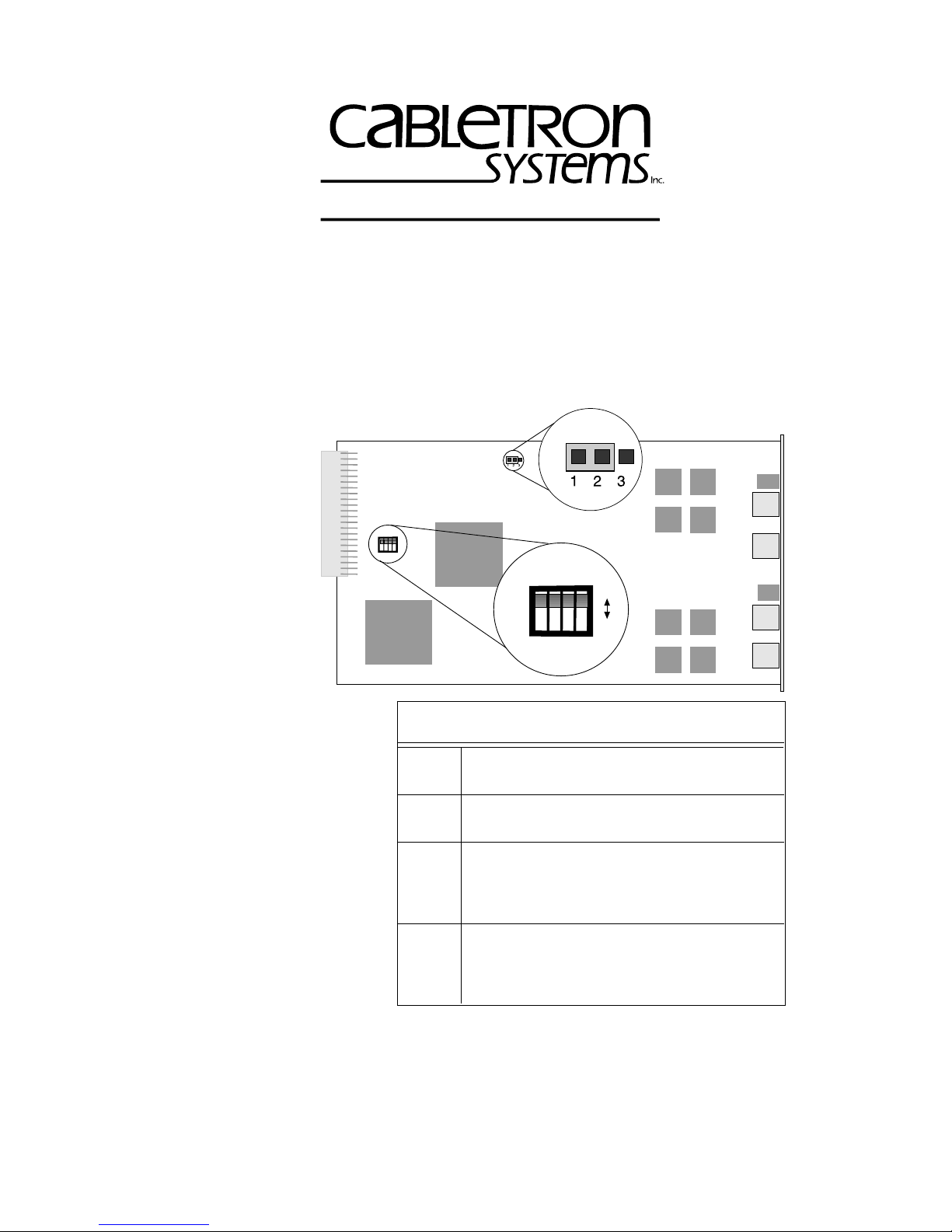
SW1
1234
SW1
ON
OFF
1234
Switch Configuration Table
SW1 Settings
On – Enable RI port
1
Off – Disable RI port
On – Enable RO port
2
Off – Disable RO port
On – Enable autowrap on RI
(for connection to Cabletron devices)
3
Off – Disable autowrap on RI
(for use with other vendor devices)
On – Enable autowrap on RO
(for connection to Cabletron devices)
4
Off – Disable autowrap on RO
(for use with other vendor devices)
Location of SW1 Switchblock And Jumper P1
(Default Settings)
Copyright 1997 by Cabletron Systems, Inc., P.O. Box 5005, Rochester, NH 03866-5005
All Rights Reserved
Printed in the United States of America
Order Number: 9032130-01 July, 1997
QR-1
Page 2

QR.1.1 Selecting The Ring Speed
Use jumper P1 to select the MCC-CRIO ring speed.
Ring Speed Setting Put Jumper P1 Sleeve Over
16 Mbps Pins 1 and 2 (Default setting)
4 Mbps Pins 2 and 3
QR.1.2 Setting Port Configurations
The RI/RO ports have an autowrap capability (transmit phantom current)
to close the ring, when:
• A cable is cut
• A cable fails
• A cable is not attached to a port
The
autowrap capability
connection of Cabletron devices to the RI/RO ports.
Autowrap must be enabled at both ends of the cable. Ensure
NOTE
that the Cabletron device at the other end has autowrap
enabled.
is set at the factory (default configuration) to allow the
You must disable autowrap to connect the RI/RO ports to the devices of
other vendors.
If autowrap is disabled, a beaconing condition may occur
!
CAUTION
before a cable can be attached. To avoid this condition connect
the cable before y ou insert the MCC-CRIO into the MCC-16, or
perform the connection with the MCC-16 shut off.
QR-2
Page 3

Configuration Switch Settings
Connect the RI of the
MCC-CRIO to the RO of a
Cabletron device.
Connect the RO of the
MCC-CRIO to the RI of a
Cabletron device.
Connect the RI of the
MCC-CRIO to the RO of another
vendor device.
Connect the RO of the
MCC-CRIO to the RI of another
vendor device.
1 – On (Default setting)
3 – On (Default setting)
2 – On (Default setting)
4 – On (Default setting)
1 – On
3 – Off
2 – On
4 – Off
QR.2 LED FUNCTIONS
Consult the diagram to help interpret LED indications.
MCC-CRIO
P1
PWR
RI16 Mb
P
1
R
I
RO
P2
R
O
P
2
PWR
RO
P2
MCC-CRIO LEDs
P1
RI16 Mb
PWR - Power
The
PWR
LED remains lighted GREEN during normal operation,
indicating the reception of power . If the LED is of f, the MCC-CRIO is not
receiving power.
QR-3
Page 4

16 Mb - Ring Speed
The
16 Mb
LED lights YELLOW to indicate a 16 Mbps ring speed. An
unlit LED indicates a ring speed of 4 Mbps.
P1 and P2 - Ports
The P1 and P2 LEDs indicate the status of the associated lobe port, as
described in the table below.
LED Activity Meaning
GREEN Phantom current present (port inserted).
OFF No phantom current present (port wrapped).
Blinking RED Speed-fault condition caused the port to wrap.
RI And RO - Ports
The RI and
RO
LEDs indicate the status of the RI or RO port, as
described in the table below.
LED Activity Meaning
GREEN Active (port open).
Blinking
GREEN
OFF No activity (port wrapped).
Blinking RED Speed-fault condition caused port to wrap.
Autowrap condition (port wrapped).
QR-4
 Loading...