

Cabletron Systems IRM Installation Manual

INTELLIGENT REPEATER MODULE
(IRM)
INSTALLATION GUIDE
CABLETRON SYSTEMS, P.O. Box 5005, Rocheter, NH 03867-5005


NOTICE
Cabletron Systems reserves the right to make changes in specifications and other information
contained in this document without prior notice. The reader should in all cases consult Cabletron
Systems to determine whether any such changes have been made.
The hardware, firmware, or software described in this manual is subject to change without notice.
IN NO EVENT SHALL CABLETRON SYSTEMS BE LIABLE FOR ANY INCIDENTAL,
INDIRECT, SPECIAL, OR CONSEQUENTIAL DAMAGES WHATSOEVER (INCLUDING BUT
NOT LIMITED TO LOST PROFITS) ARISING OUT OF ORRELATED TO THIS MANUAL OR
THE INFORMATION CONTAINED IN IT, EVEN IF CABLETRON SYSTEMS HAS BEEN
ADVISED OF, KNOWN, OR SHOULD HAVE KNOWN, THE POSSIBILITY OF SUCH
DAMAGES.
© Copyright July 1991 by:
Cabletron Systems, Inc.
P.O. Box 5005, Rochester, NH 03867-5005
All Rights Reserved
Printed in the United States of America
Order number: 9030033-03 July 91
LANVIEW
SPECTRUM, Remote LANVIEW/Windows, IRM, IRM/LM, MMAC-8, MMAC-8FNB
MMAC-5FNB, MMAC-3, MMAC-3FNB, PSM, PSM-R, MMAC-5PSM, THN-MIM
LAN-MD
is a registered trademark of Cabletron Systems, Inc.
, and
are trademarks of Cabletron Systems, Inc.
,
i

NOTICE
FCC NOTICE
This device complies with Part 15 of FCC rules. Operation is subject to the follo wing two conditions:
(1) this device may not cause harmful interference, and (2) this device must accept any interference
received, including interference that may cause undesired operation.
WARNING
installed properly and used in accordance with the instruction manual, may cause interference to radio
communications. It has been tested and found to comply with the limits for a Class A digital device
pursuant to Part 15 of FCC Rules, which are designed to provide reasonable protection against such
interference in a commercial environment. Operation of this equipment in a residential area is likely
to cause interference in which case the user at his own expense will be required to take whate ver steps
may be necessary to correct the interference.
If this equipment does cause interference to radio or television, which can be determined by turning
the equipment off and on, the user is encouraged to try to correct the interference by one or more of
the following measures:
• Re-orient the receiving antenna.
• Relocate the antenna with respect to the MMAC.
• Move the MMAC away from the antenna.
• Plug the MMAC into a different outlet so that the MMAC and the receiver are on different
If necessary, the user should consult the dealer or an experienced radio/television technician for
additional suggestions. The user may33 find the following booklet prepared by the Federal
Communication Commission helpful:
“How to Identify and Resolve Radio TV Interference Problems”
This booklet is available from the U.S. Government Printing Office, Washington D.C. 20402 - Stock
No. 004-000-00345-4.
: This equipment uses and generates and can radiate radio frequency energy and if not
branch circuits.
ii

CONTENTS
CHAPTER 1 INTRODUCTION
1.1 USING THIS MANUAL........................................................................1-1
1.2 GETTING HELP ....................................................................................1-2
1.3 THE INTELLIGENT REPEATER MODULE (IRM) ...........................1-2
1.4 REPEATER FUNCTIONALITY ...........................................................1-4
1.5 NETWORK MANAGEMENT CAPABILITIES...................................1-4
1.6 RELATED MANUALS..........................................................................1-5
CHAPTER 2 NETWORK REQUIREMENTS/SPECIFICATIONS
2.1 NETWORK REQUIREMENTS.............................................................2-1
2.1.1 AUI Port Requirements....................................................2-1
2.1.2 Thin-Net Requirements....................................................2-1
2.2 OPERATING SPECIFICATION ...........................................................2-2
CHAPTER 3 INSTALLING THE IRM
3.1 UNPACKING THE IRM........................................................................3-1
3.2 SETTING THE IRM JUMPERS ..........................................................3-1
3.2.1 Setting the Battery Enable/Disable Jumper .....................3-1
3.2.2 Setting the Default Setting Jumper (JP4).........................3-3
3.2.3 Setting the THN-MIM Jumper (JP2)...............................3-3
3.3 INSTALLING THE IRM........................................................................3-4
3.4 CONNECTING THE IRM TO THE NETWORK .................................3-5
3.4.1 Connecting to the Network Via the AUI Port..................3-5
3.4.2 Connecting to the Network Via the BNC Port.................3-8
CHAPTER 4 TESTING AND LANVIEW
4.1 INSTALLATION CHECK-OUT ..........................................................4-1
4.2 USING LANVIEW................................................................................4-2
4.3 USING THE RESET SWITCH.............................................................4-3
iii

CONTENTS
iv

CHAPTER 1
INTRODUCTION
Welcome to the Cabletron Systems
(IRM™) Installation Guide
. We have designed this manual to serve as a
Intelligent Repeater Module
simple installation and reference guide for the IRM, and to explain the
capabilities and special features of the IRM. The IRM provides an IEEE
802.3 Repeater with network management capabilities for use in a
™
Cabletron Systems Multi Media Access Center (MMAC
).
You should read through this manual to gain a full understanding of the
IRM and its capabilities.
1.1 USING THIS MANUAL
Chapter 1,
IRM. The chapter includes an explanation of the IRM's repeater
functionality and a discussion of the IRM's Management capabilities. The
chapter concludes with a list of related manuals.
Chapter 2,
network requirements that must be met before you install the IRM. The
specifications for the IRM are also included in this chapter .
Introduction
, discusses the capabilities of Cabletron Systems'
Installation Requirements/Specifications
, contains a list of
Chapter 3,
Installing the IRM
, contains instructions for installing the
IRM into the MMAC. The chapter also includes instructions for
connecting the IRM to the network.
Chapter 4,
Testing and T r oubleshooting
, provides procedures for testing
and troubleshooting the installation of the IRM. Instructions for using
LANVIEW, Cabletron Systems' built-in visual diagnostic and status
monitoring system, are also included.
We assume that you have a general working knowledge of Ethernet or
IEEE 802.3 type data communications networks and their physical layer
components.
1-1

INTRODUCTION
1.2 GETTING HELP
If you need additional support related to the Cabletron Systems IRM, or if
you have any questions, comments or suggestions related to this manual,
feel free to contact Cabletron Systems' Technical Support at:
Cabletron Systems, Inc.
35 Industrial Way, P.O. Box 5005
Rochester, NH 03867-5005
Phone: (603) 332-9400
1.3 THE INTELLIGENT REPEATER MODULE (IRM)
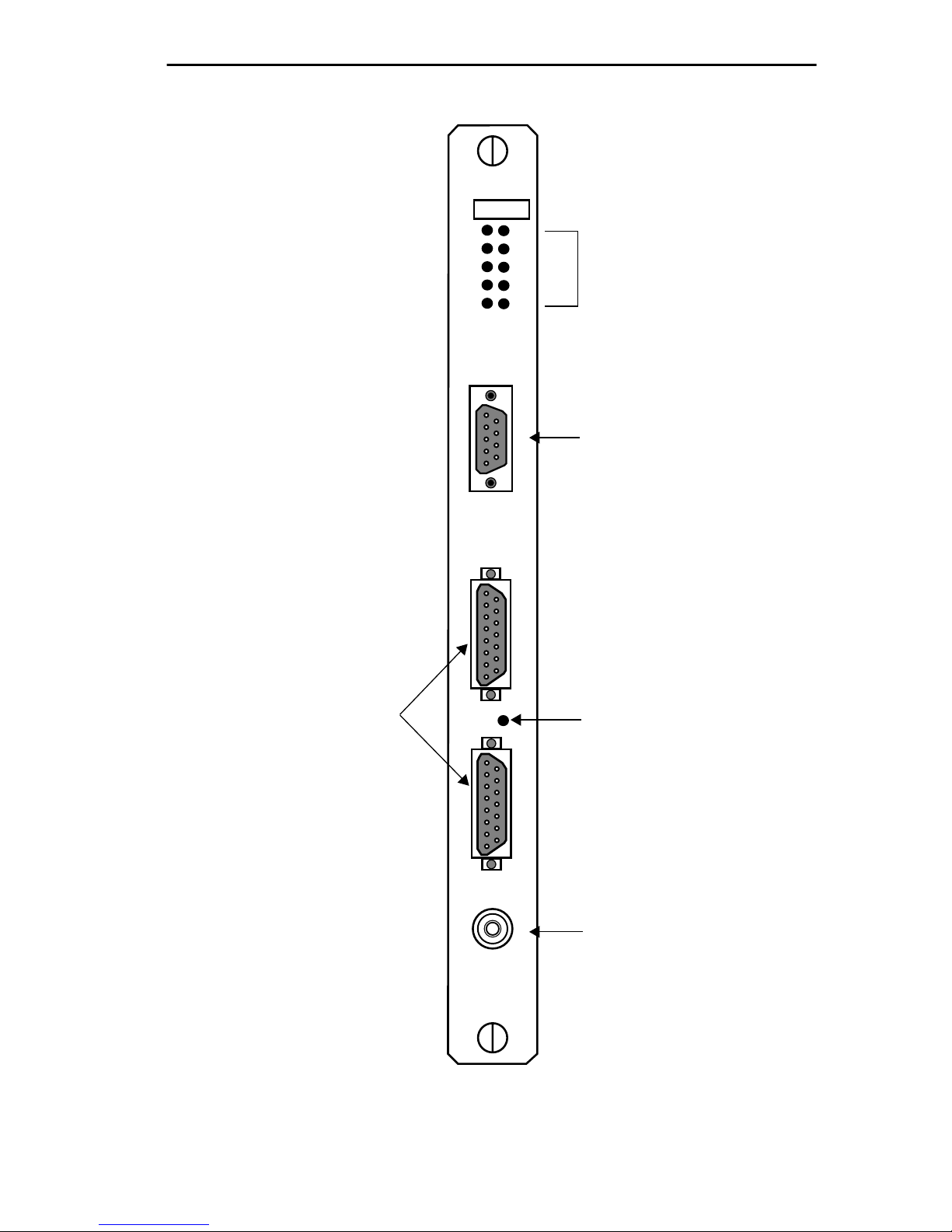
The Cabletron Systems Intelligent Repeater Module (IRM) (Fig. 1-1) is
the heart of the Cabletron Systems Multi Media Access Center. The IRM
incorporates an IEEE 803.3 repeater to allow maximum data paths
between devices connected MMAC.
The IRM can be controlled and monitored by a variety of Cabletron
System Network Management packages. These include Cabletron
Systems Remote LANVIEW/Windows™ and Cabletron Systems
SPECTRUM™. Additionally, the IRM can be controlled and monitored
by IRM/LM™ - Local Management for the IRM via a terminal connected
locally .
The IRM incorporates three IEEE 802.3 compliant ports that connect to
external network segments: two AUI ports and one BNC port. The AUI
ports allow you to connect the module to a variety of Ethernet
transmission media including twisted pair, fiber optic, and/or thick or thin
Ethernet coaxial cable via an external transceiver. The BNC port can be
used to connect a Thin-Net Segment to the IRM.
A standard 9 pin RS232 console port that allows you to access IRM/LM
and a Reset Switch to initialize the IRM's processor are also built into the
IRM's front panel.
The IRM also incorporates Cabletron Systems' LANVIEW Status
Monitoring and Diagnostics Systems. Should a problem arise, such as a
power failure or a cable fault, LANVIEW's LEDs will help you to
diagnose it. LANVIEW LEDs on the IRM advise you whether the module
is receiving power, whether an error has been detected with the IRM,
whether the IRM is receiving packets from any segment
1-2
IRM
SN
FAIL CLN
INTRODUCTION
15 Pin DB-15
AUI Ports
1
2
3
RESET
LANVIEW LEDs
R
P
C
O
K
K
C
O
N
S
O
L
E
A
U
I
1
9 Pin RS232 Port
Reset Switch
Figure 1-1 Intelligent Repeater Module (IRM)
A
U
I
2
M
A
U
3
BNC Port
1-3
 Loading...