

Page 1
HSIM-W6
USER’S GUIDE
LNK
STS
WIDE AREA1
TELCO
LNK
STS
ASYNC
LNK
STS
WIDE AREA2
TELCO
HSIM-W6
CPU
225700
Page 2

Page 3

Notice
Cabletron Systems reserves the right to make changes in specifications and other information contained in this document without prior
notice. The reader should in all cases consult Cabletron Systems to determine whether any such changes have been made.
The hardware, firmware, or software described in this manual is subject to change without notice.
IN NO EVENT SHALL CABLETRON SYSTEMS BE LIABLE FOR ANY INCIDENTAL, INDIRECT, SPECIAL, OR
CONSEQUENTIAL DAMA GES WHATSOEVER (INCLUDING BUT NOT LIMITED T O LOST PROFITS) ARISING OUT OF OR
RELATED TO THIS MANUAL OR THE INFORMATION CONTAINED IN IT, EVEN IF CABLETRON SYSTEMS HAS BEEN
ADVISED OF, KNOWN, OR SHOULD HAVE KNOWN, THE POSSIBILITY OF SUCH DAMAGES.
Copyright September 1997 by Cabletron Systems, Inc., P.O. Box 5005, Rochester, NH 03866-5005
All Rights Reserved
Printed in the United States of America
Part Number: 9032257-01 September 1997
Cabletron Systems, LANVIEW, QuickSET,
trademarks of Cabletron Systems, Inc.
All other product names mentioned in this manual may be trademarks or registered trademarks of their respective companies.
FCC Notice
This device complies with Part 15 of the FCC rules. Operation is subject to the following two conditions: (1) this device may not cause
harmful interference, and (2) this device must accept any interference received, including interference that may cause undesired
operation.
NOTE:
This equipment has been tested and found to comply with the limits for a Class A digital device, pursuant to Part 15 of the
FCC rules. These limits are designed to provide reasonable protection against harmful interference when the equipment is operated in a
commercial environment. This equipment uses, generates, and can radiate radio frequency energy and if not installed in accordance
with the operator’s manual, may cause harmful interference to radio communications. Operation of this equipment in a residential area
is likely to cause interference in which case the user will be required to correct the interference at his own expense.
WARNING:
could void the user’s authority to operate the equipment.
Changes or modifications made to this device which are not expressly approved by the party responsible for compliance
and
SPECTRUM
are registered trademarks, and
HSIM
and
QuickSTART
are
DOC Notice
This digital apparatus does not exceed the Class A limits for radio noise emissions from digital apparatus set out in the Radio
Interference Regulations of the Canadian Department of Communications.
Le présent appareil numérique n’émet pas de bruits radioélectriques dépassant les limites applicables aux appareils numériques de la
class A prescrites dans le Règlement sur le brouillage radioélectrique édicté par le ministère des Communications du Canada.
HSIM-W6 User’s Guide i
Page 4

Notice
VCCI Notice
This is a Class A product based on the standard of the Voluntary Control Council for Interference by Information Technology
Equipment (VCCI). If this equipment is used in a domestic environment, radio disturbance may arise. When such trouble occurs, the
user may be required to take corrective actions.
Cabletron Systems, Inc. Program License Agreement
IMPORTANT:
This document is an agreement between you, the end user, and Cabletron Systems, Inc. (“Cabletron”) that sets forth your rights and
obligations with respect to the Cabletron software program (the “Program”) contained in this package. The Program may be contained
in firmware, chips or other media. BY UTILIZING THE ENCLOSED PRODUCT, YOU ARE AGREEING TO BECOME BOUND BY
THE TERMS OF THIS AGREEMENT, WHICH INCLUDES THE LICENSE AND THE LIMITATION OF WARRANTY AND
DISCLAIMER OF LIABILITY. IF YOU DO NOT AGREE TO THE TERMS OF THIS AGREEMENT, PROMPTLY RETURN THE
UNUSED PRODUCT TO THE PLACE OF PURCHASE FOR A FULL REFUND.
Before utilizing this product, carefully read this License Agreement.
Cabletron Software Program License
1. LICENSE
conditions of this License Agreement.
You may not copy , reproduce or transmit an y part of the Program except as permitted by the Cop yright Act of the United States or
as authorized in writing by Cabletron.
2. OTHER RESTRICTIONS. You may not reverse engineer, decompile, or disassemble the Program.
3. APPLICABLE LA W. This License Agreement shall be interpreted and governed under the laws and in the state and federal courts
of New Hampshire. You accept the personal jurisdiction and venue of the New Hampshire courts.
. You have the right to use only the one (1) copy of the Program provided in this package subject to the terms and
ii HSIM-W6 User’s Guide
Page 5

Exclusion of Warranty and Disclaimer of Liability
Notice
1. EXCLUSION OF
expressed or implied, concerning the Program (including its documentation and media).
CABLETRON DISCLAIMS ALL WARRANTIES, OTHER THAN THOSE SUPPLIED TO YOU BY CABLETRON IN
WRITING, EITHER EXPRESSED OR IMPLIED, INCLUDING BUT NOT LIMITED TO IMPLIED WARRANTIES OF
MERCHANTABILITY AND FITNESS FOR A PARTICULAR PURPOSE, WITH RESPECT TO THE PROGRAM, THE
ACCOMP ANYING WRITTEN MA TERIALS, AND ANY A CCOMP ANYING HARDWARE.
2. NO LIABILITY FOR CONSEQUENTIAL DAMAGES. IN NO EVENT SHALL CABLETRON OR ITS SUPPLIERS BE
LIABLE FOR ANY DAMAGES WHATSOEVER (INCLUDING, WITHOUT LIMITATION, DAMAGES FOR LOSS OF
BUSINESS, PROFITS, BUSINESS INTERRUPTION, LOSS OF BUSINESS INFORMATION, SPECIAL, INCIDENTAL,
CONSEQUENTIAL, OR RELIANCE DAMAGES, OR OTHER LOSS) ARISING OUT OF THE USE OR INABILITY TO USE
THIS CABLETRON PRODUCT, EVEN IF CABLETRON HAS BEEN ADVISED OF THE POSSIBILITY OF SUCH
DAMAGES. BECAUSE SOME STATES DO NOT ALLOW THE EXCLUSION OR LIMITATION OF LIABILITY FOR
CONSEQUENTIAL OR INCIDENTAL DAMAGES, OR ON THE DURATION OR LIMITATION OF IMPLIED
WARRANTIES, IN SOME INSTANCES THE ABOVE LIMITATIONS AND EXCLUSIONS MAY NOT APPLY TO YOU.
WARRANTY. Except as may be specifically provided by Cabletron in writing, Cabletron makes no warranty,
United States Government Restricted Rights
The enclosed product (a) was developed solely at priv ate e xpense; (b) contains “restricted computer software” submitted with restricted
rights in accordance with Section 52227-19 (a) through (d) of the Commercial Computer Software - Restricted Rights Clause and its
successors, and (c) in all respects is proprietary data belonging to Cabletron and/or its suppliers.
For Department of Defense units, the product is licensed with “Restricted Rights” as defined in the DoD Supplement to the Federal
Acquisition Regulations, Section 52.227-7013 (c) (1) (ii) and its successors, and use, duplication, disclosure by the Government is
subject to restrictions as set forth in subparagraph (c) (1) (ii) of the Rights in Technical Data and Computer Software clause at
252.227-7013. Cabletron Systems, Inc., 35 Industrial Way, Rochester, New Hampshire 03867-0505.
HSIM-W6 User’s Guide iii
Page 6

Notice
DECLARATION OF CONFORMITY
Application of Council Directive(s):
Manufacturer’s Name:
Manufacturer’s Address:
European Representative Name:
European Representative Address:
Conformance to Directive(s)/Product Standards:
Equipment T ype/Environment:
W e the undersigned, hereby declare, under our sole responsibility, that the equipment packaged with this notice conforms to the
above directives.
89/336/EEC
73/23/EEC
91/263/EEC
Cabletron Systems, Inc.
35 Industrial Way
PO Box 5005
Rochester, NH 03867
Mr. J. Solari
Cabletron Systems Limited
Nexus House, Newbury Business Park
London Road, Newbury
Berkshire RG13 2PZ, England
EC Directive 89/336/EEC
EC Directive 73/23/EEC
EC Directive 91/263/EEC
EN 55022
EN 50082-1
EN 60950
Networking Equipment, for use in a Commercial or Light Industrial
Environment.
Manufacturer Legal Representative in Europe
Mr. Ronald Fotino Mr. J. Solari
___________________________________ ___________________________________
Full Name Full Name
Principal Compliance Engineer Managing Director - E.M.E.A.
___________________________________ ___________________________________
Title Title
Rochester, NH, USA Newbury, Berkshire, England
___________________________________ ___________________________________
Location Location
iv HSIM-W6 User’s Guide
Page 7

CHAPTER 1 INTRODUCTION
Structure of this Guide ....................................................................................1
Related Documents ........................................................................................2
Document Conventions...................................................................................3
Getting Help....................................................................................................4
CHAPTER 2 ABOUT THE HSIM-W6
HSIM-W6 Hardware........................................................................................5
WAN Connection......................................................................................5
Additional Features...................................................................................7
Remote Management Capabilities..................................................................7
Optional Feature .............................................................................................8
HSIM-W6 Firmware Support...........................................................................8
WAN Protocols.........................................................................................8
Inverse Multiplexing................................................................................10
Firmware Data Compression..................................................................10
HDLC......................................................................................................11
DHCP and NAT......................................................................................11
Point-to-Point Protocol............................................................................12
PAP and CHAP Security ........................................................................12
LQM........................................................................................................13
Multilink Protocol ....................................................................................13
ISDN.......................................................................................................14
ISDN Back-up.........................................................................................15
HDSL......................................................................................................16
Bridging and Routing..............................................................................16
Bridging and Routing Protocol Filtering..................................................18
System Passwords.................................................................................18
Simple Network Management Protocol (SNMP) ....................................19
Software and Firmware Upgrades..........................................................22
Contents
HSIM-W6 User’s Guide v
Page 8

Contents
CHAPTER 3 ISDN LINE ORDERING AND CONFIGURATION
Arranging ISDN Service................................................................................23
Telephone Switch Support............................................................................24
ISDN BRI Line Configuration ........................................................................24
ISDN BRI Configurations........................................................................25
SPIDs, Directory Numbers and Telephone Numbers.............................25
Telephone Switch Parameters......................................................................26
CHAPTER 4 PLANNING FOR HSIM-W6 ISDN CONFIGURATION
Configuration Process and Terminology.......................................................29
Collect Network Information ...................................................................30
Names and Passwords...........................................................................30
ISDN Line Information ............................................................................31
Network Information Diagrams...............................................................32
Network Information Tables....................................................................38
Sample Configuration....................................................................................42
Names and Passwords Example..................................................................48
CHAPTER 5 INSTALLATION
Unpacking the HSIM-W6...............................................................................49
Guidelines for Installations............................................................................49
Installing Interface Modules ..........................................................................50
Installing WAN Port Interface Modules (WPIMs) ..........................................50
CSX-COMP/ENCR Installation .....................................................................52
Installing an HSIM.........................................................................................54
Installing an HSIM in an Interface Module..............................................54
Installing an HSIM in a SmartSWITCH Chassis.....................................56
vi HSIM-W6 User’s Guide
Page 9

Contents
CHAPTER 6 HSIM-W6 CONFIGURATION WITH
HSIM Configuration.......................................................................................61
HSIM Configuration Window ..................................................................62
Wide Area 1 and 2 Configuration..................................................................66
Wide Area T1 Configuration Window .....................................................67
Wide Area E1 Configuration Window .....................................................70
Wide Area DI Configuration Window......................................................72
Wide Area Synchronous Configuration Window.....................................75
Wide Area DDS Configuration Window..................................................78
Wide Area HDSL Configuration Window................................................80
Wide Area Frame Relay Time Slot Configuration Window.....................82
Wide Area PPP Time Slot Configuration Window ..................................84
Wide Area HDSL Time Slot Configuration Window................................86
Bridging and Routing Configuration..............................................................88
Bridging and Routing Configuration Window..........................................88
Bridging and Routing (WAN Frame Type) Configuration Window..........94
Routing Configuration Window...............................................................96
IP Routing Configuration ........................................................................97
IPX Routing Configuration......................................................................97
Advanced Routing Configuration Window............................................100
QuickSET Pull-Down Menus ................................................................106
Advanced Configuration Menu .............................................................111
Compression & Congestion Window....................................................112
QUICKSET
CHAPTER 7 GENERAL CONFIGURATION USING LOCAL MANAGEMENT
Chapter Organization..................................................................................115
Local Management Overview......................................................................116
Management Agent ..............................................................................116
Local vs. Remote Management............................................................116
Local Management Screen Elements...................................................117
Local Management Keyboard Conventions..........................................119
Navigating Within Local Management Screens....................................120
Local Management Screen Hierarchy ..................................................121
HSIM-W6 User’s Guide vii
Page 10

Contents
Accessing Local Management....................................................................121
Establishing a TELNET Connection .....................................................121
Using the Menu Screens ......................................................................122
Main Menu Screen......................................................................................123
Setup Menu Screen ....................................................................................124
System Level Screen..................................................................................126
Setting the System Date.......................................................................128
Setting the System Time ......................................................................128
Setting the Host IP Address .................................................................129
Setting the Subnet Mask ......................................................................129
Setting the Default Gateway.................................................................130
Setting the Default Interface.................................................................130
SNMP Community Names Screen..............................................................131
Community Name Access Policy..........................................................132
Setting SNMP Community Names .......................................................132
SNMP Traps Screen...................................................................................133
Trap Table Screen Fields .....................................................................133
Setting the SNMP Trap Destination......................................................134
Flash Download Screen..............................................................................135
Selecting a Flash Download Method....................................................136
Bridge Setup Screen...................................................................................139
Bridge Setup Screen Fields..................................................................139
Selecting a Spanning Tree Protocol.....................................................140
Selecting the Bridge Port Administrative Status...................................140
Selecting the Bridge Port Pair Administrative Status............................141
Router Setup Screen...................................................................................142
Router Setup Screen Fields .................................................................142
IP Configuration Screen..............................................................................143
IP Configuration Screen Fields.............................................................143
IP General Config Screen.....................................................................144
IP General Configuration Status Fields ................................................144
IP General Configuration Fields ...........................................................145
Enabling the RIP on a Port...................................................................151
viii HSIM-W6 User’s Guide
Page 11

IPX Configuration Screen............................................................................153
IPX Configuration Fields.......................................................................153
IPX General Configuration Screen .......................................................155
IPX General Configuration Status Fields..............................................155
IPX General Configuration Fields.........................................................156
IPX Routing over Frame Relay.............................................................159
Enabling the IPX SAP Protocol on a Port.............................................160
Enabling the RIP on a Port...................................................................162
WAN Setup .................................................................................................164
WAN Physical Configuration Screen Fields .........................................165
WAN Interface Configuration Screen..........................................................166
WAN Interface Configuration Screen Fields.........................................166
CHAPTER 8 MIB NAVIGATOR
Chapter Organization..................................................................................169
MIB Navigator Screen.................................................................................170
Managing Device MIBs.........................................................................170
MIB Navigator Command Set Overview .....................................................171
Conventions for MIB Navigator Commands .........................................172
Navigation Commands................................................................................173
Other Commands........................................................................................182
Special Commands.....................................................................................196
Contents
HSIM-W6 User’s Guide ix
Page 12

Contents
CHAPTER 9 TROUBLESHOOTING
Troubleshooting HSIM-W6 Hardware.........................................................201
Power (PWR) LED is OFF....................................................................201
Processor (CPU) LED is OFF...............................................................201
Processor (CPU) LED is RED ..............................................................202
ASYNC Console Connection ......................................................................202
Link (LNK) LED is OFF.........................................................................202
Link (LNK) LED is RED or GREEN ......................................................202
Link (LNK) LED is AMBER ...................................................................202
Status (STS) LED is OFF .....................................................................202
Status (STS) LED is AMBER................................................................202
Status (STS) LED is GREEN or GREEN (Blinking)..............................202
Status (STS) LED is AMBER (Blinking)................................................203
Troubleshooting the WAN...........................................................................203
Link (LNK) LED is OFF.........................................................................203
Link (LNK) LED is RED ........................................................................203
Link (LNK) LED is AMBER ...................................................................203
Status (STS) LED is OFF .....................................................................204
Status (STS) LED is RED.....................................................................205
Status (STS) LED is AMBER................................................................205
Status (STS) LED is AMBER (blinking)................................................206
Status (STS) LED is GREEN................................................................206
Investigating Software Configuration Problems..........................................207
Connection to Device Fails During Software Configuration..................207
User Cannot Communicate with Remote Network Station...................207
x HSIM-W6 User’s Guide
Page 13

APPENDIX A WPIM CABLE SPECIFICATIONS
WPIM-T1.....................................................................................................209
WPIM-SY ....................................................................................................211
EIA-449.................................................................................................212
V.35 ......................................................................................................213
EIA-232.................................................................................................215
X.21 ......................................................................................................216
EIA-530, EIA-530 ALT A, EIA-530 A, and EIA-530 A ALT A................217
WPIM-DDS..................................................................................................219
WPIM-E1.....................................................................................................220
WPIM-DI......................................................................................................222
WPIM-HDSL................................................................................................223
WPIM-S/T....................................................................................................224
APPENDIX B SPECIFICATIONS AND STANDARDS COMPLIANCE
Regulatory Compliance...............................................................................225
Individual WPIM Regulatory Compliance....................................................226
WPIM-TI ...............................................................................................226
WPIM-SY..............................................................................................226
WPIM-DDS...........................................................................................227
WPIM-E1 ..............................................................................................227
WPIM-DI...............................................................................................227
WPIM-S/T.............................................................................................228
WPIM-HDSL.........................................................................................228
Contents
APPENDIX C NETWORK INFORMATION WORKSHEETS
APPENDIX D FCC PART 68 - USER’S INFORMATION FOR HSIM-W6
APPENDIX E GLOSSARY
INDEX
HSIM-W6 User’s Guide xi
Page 14

Contents
xii HSIM-W6 User’s Guide
Page 15

1
Introduction
Welcome to the Cabletron Systems
configuration information, hardware specifications and troubleshooting tips for the HSIM-W6.
This document also provides guidelines for routing and bridging over Wide Area Networks
(WANs).
HSIM-W6 User’s Guide
. This guide provides basic
Structure of this Guide
This guide is organized as follows:
Chapter 1, Introduction
Chapter 2, About the HSIM-W6
and features.
Chapter 3, ISDN Line Ordering and Configuration
ISDN service from the telephone company.
Chapter 4, Planning for CSX400 ISDN Configuration
process.
Chapter 5, Installation
Chapter 6, HSIM-W6 Configuration with QuickSET
HSIM-W6 to a Wide Area Network (WAN) using Cabletron Systems
utility.
, details document conventions and pro vides information on getting help.
, describes the hardware components and software protocols
provides the information you need to order
describes the router configuration
, provides detailed installation instructions.
, provides instructions on connecting the
QuickSET
management
Chapter 7, General Configuration Using Local Management
configuring the HSIM-W6 through a TELNET connection.
Chapter 8, MIB Navigator
Chapter 9, Troubleshooting
on the HSIM-W6.
Appendix A, WPIM Cable Specifications
WPIMs.
Appendix B, Specifications and Standards Compliance
safety and compliance information.
, explains how to use the MIB Navigator utility.
, provides detailed troubleshooting tips using the LANVIEW LEDs
, provides part number and connector information for
, provides hardware specifications and
, provides instructions for
HSIM-W6 User’s Guide 1
Page 16

Chapter 1: Introduction
Appendix C, Network Information Worksheets
worksheets.
Appendix D, FCC Part 68 - User’s Information For HSIM-W6
to comply with FCC Rules, Part 68.
Appendix E, Glossary
, defines commonly used terms.
, provides blank network information
, provides instructions required
Related Documents
Use the Cabletron Systems
HSIM-W6.
Use the
before beginning configuration.
Use the appropriate Cabletron Systems WPIM Local Management Guide to connect your
HSIM-W6 to a WAN using a TELNET connection.
READ ME FIRST!
QuickSTART Guide
document included with the HSIM-W6 to set up your computer
located in the
QuickSET
CD case to install the
2 HSIM-W6 User’s Guide
Page 17
Document Conventions
The following conventions are used throughout this guide:
Note
NOTE
TIP
symbol. Calls the reader’s attention to any item of information that may be of
special importance.
Tip
symbol. Conveys helpful hints concerning procedures or actions.
Chapter 1: Introduction
!
CAUTION
WARNING
Caution
Electrical Hazard Warning
personal injury or death due to an electrical hazard.
Warning
symbol. Contains information essential to avoid damage to the equipment.
symbol. Warns against an action that could result in
symbol. Warns against an action that could result in personal injury or death.
HSIM-W6 User’s Guide 3
Page 18

Chapter 1: Introduction
Getting Help
If you need additional support related to this device, or if you have any questions, comments, or
suggestions concerning this manual, contact the Cabletron Systems Global Call Center:
Phone (603) 332-9400
Internet mail support@ctron.com
FTP ctron.com (134.141.197.25)
Login
Password
BBS (603) 335-3358
Modem setting 8N1: 8 data bits, No parity, 1 stop bit
For additional information about Cabletron Systems or our products,
visit our World Wide Web site: http://www.cabletron.com/
For technical support, select Service and Support.
Before calling the Cabletron Systems Global Call Center, have the following information ready:
•
A description of the failure
• A description of any action(s) already taken to resolve the problem (e.g., changing mode
switches, rebooting the unit, etc.)
anonymous
your email address
• A description of your network environment (layout, cable type, etc.)
• Network load and frame size at the time of trouble (if known)
• The serial and revision numbers of all Cabletron Systems products in the network
• The device history (i.e., have you returned the device before, is this a recurring problem, etc.)
• Any previous Return Material Authorization (RMA) numbers
4 HSIM-W6 User’s Guide
Page 19
2
About the HSIM-W6
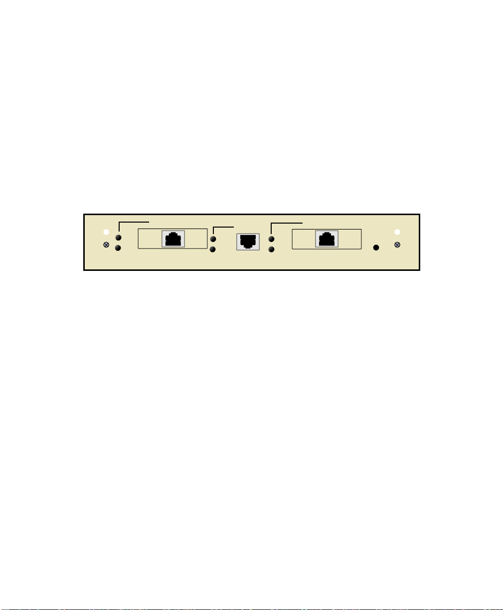
The HSIM-W6 (Figure 1) offers high-speed W ide Area Netw ork (WAN) access to remote sites via
two WAN Port Interface Modules (WPIMs) to the device into which it is installed. The HSIM-W6
supports IEEE 802.1d transparent bridging, IP routing, IPX routing between the host device and
the two WAN connections, ISDN, Dynamic Host Configuration Protocol (DHCP), Network
Address Translation (NAT), and Inverse Multiplexing (IMUX) between Ethernet LANs across a
WAN resource. In addition, the ASYNC port connector can be used as a local console connection.
HSIM-W6
CPU
225700
LNK
STS
WIDE AREA1
TELCO
ASYNC
LNK
STS
Figure 1 The HSIM-W6
LNK
STS
WIDE AREA2
TELCO
HSIM-W6 Hardware
This section details the HSIM-W6 hardware capabilities.
WAN Connection
The HSIM-W6 supports Point-to-Point Protocol (PPP) including: Link Control Protocol (LCP),
BNCP, IPCP, IPXCP, LQM, Multilink Protocol (MP) and CHAP and PAP, ISDN-BRI and Frame
Relay protocols through one of the following WAN port interface modules (WPIMs):
• The WPIM-T1 provides a T1 interface through a front panel RJ45 port and includes a built-in
Channel Service Unit/Digital Service Unit (CSU/DSU) for direct connection to a T1 line. The
WPIM-T1 provides both Full T1 or Fractional T1 using 56 or 64 Kbps timeslots, with a total
throughput of up to 1.544 Mbps.
HSIM-W6 User’s Guide 5
Page 20

Chapter 2: About the HSIM-W6
• The WPIM-SY provides a synchronous serial connection of up to 2.048 Mbps to external
communications equipment (e.g., a multiplexer or CSU/DSU). The WPIM-Sync uses a
subminiature 26-pin connector that supports the following electrical signal interfaces (see the
Synchronous WAN Configuration Window section in Chapter 4 for specific cable part
numbers):
• EIA-RS449
• V.35
• EIA-RS232D
• X.21
• EIA-RS530
• EIA-530A
• RS530 AL T A
• RS530A AL T A
• The WPIM-DDS provides a 56 Kbps or 64 Kbps Digital Data Service (DDS) connection. The
WPIM-DDS supports remote CSU diagnostic or 64 Kbps clear channel loopback and
non-latching remote DSU diagnostic loopback.
• The WPIM-E1 provides an E1 interface through a front panel RJ45 port and includes a built-in
CSU/DSU for direct connection to an E1 line. The WPIM-E1 provides both Full E1 or
Fractional E1 using 56 or 64 Kbps timeslots with a total throughput of up to 2 Mbps.
• The WPIM-DI provides a T1 interface through a front panel RJ45 port and includes a built-in
CSU/DSU for direct connection to a T1 line. The WPIM-DI provides both Full T1 or Fractional
T1 using 56 or 64 Kbps timeslots and also provides a second Drop-and-Insert interface, which
allows more than one device to share a single T1 connection.
• The WPIM-S/T provides an Integrated Services Digital Network (ISDN) 128 Kbps Basic Rate
Interface (BRI) for the HSIM-W6. The WPIM-S/T pro vides an ISDN back-up link for a remote
site or branch office when the main WPIM for a frame relay or leased line loses a connection
or becomes disabled. An NT-1 adapter is necessary for this interface in the United States.
• The WPIM-HDSL provides a connection for users in a campus environment, or ha v e access to
local subscriber loops, who want to send their data over their existing telephone lines, that may
run between floors, buildings, or other physical structures, at rates of up to 1.544 Mbps. HDSL
supports line lengths of up to 3, 657 meters (12,000 feet) over 24 AWG (American Wire Gauge)
Unshielded Twisted Pair (UTP) cabling.
6 HSIM-W6 User’s Guide
Page 21

Chapter 2: About the HSIM-W6
• The WPIM-T1/DDS provides both a T1 and DDS interface that allows you to easily switch
between the two interfaces by changing the physical cabling and reconfiguring QuickSET for
the desired interface. The WPIM-T1/DDS has the capabilities of both the WPIM-T1 and
WPIM-DDS.
Additional Features
FLASH EEPROMs — The HSIM-W6 uses FLASH Electrically Erasable Programmable
Read-Only Memory (EEPROM) that allows the downloading of new and updated firmware in
conjunction with Cabletron Systems QuickSET or any device using BootP or TFTP protocols.
LANVIEW LEDs — Cabletron Systems LANVIEW Status Monitoring and Diagnostics System is
a troubleshooting tool that helps in the diagnosing of power failures, collisions, cable faults, and
link problems. The LANVIEW LEDs are located on the HSIM-W6 front panel.
Remote Management Capabilities
The HSIM-W6 can be remotely managed with any SNMP network management system including
the following:
• Cabletron Systems SPECTRUM
• Cabletron Systems Remote SPECTRUM Portable Management Applications (SPMAs)
• Third party SNMP compliant network management packages
• Cabletron Systems QuickSET
• Cabletron Systems SPECTRUM Element Manager (SPEL)
HSIM-W6 User’s Guide 7
Page 22

Chapter 2: About the HSIM-W6
Optional Feature
Hardware Data Compression Module (CSX-COMP/ENCR) — The same industry standard
STAC Electronics Stacker LZS Compression algorithm supported by HSIM-W6 software is made
available by an optional hardware data compression module that accelerates data compression for
the HSIM-W6 over PPP and Frame Relay. Depending on the packet type and size, hardware data
compression provides a minimum of 2:1 data compression, giving 3 Mbps throughput on each T-1
WPIM interface. To use the hardware data compression module, compatible equipment (such as
the HSIM-W6, CSX200, and CSX400 or other vendors’ equipment which conforms to the
applicable standards), must be in use at both ends of the WAN link. When the hardware data
compression module is installed on the board, it automatically assumes the compression task from
software. There is no configuration necessary to prioritize hardware over software compression.
HSIM-W6 Firmware Support
The HSIM-W6 firmware supports IEEE 802.1d bridging, and IP and IPX routing, and OSI Layer 2
Inverse Multiplexing (IMUX), which allows both WAN channels to be used as a single, high
bandwidth, WAN channel. Wide Area Networking includes Point-to-Point Protocol (PPP),
Frame Relay, and ISDN. Remote access is via Full or Fractional T1, E1, Synchronous, Digital
Data Service, ISDN BRI, or HDSL connections.
This device supports industry-standard protocols, security features, compression algorithms and
network management tools to ensure interoperability with equipment from other vendors.
WAN Protocols
This device supports the following WAN protocols over the WAN port:
• Point-to-Point Compression Control Protocol (CCP) as defined by RFC 1962
• Point-to-Point Protocol (LCP) as defined by RFC 1661
• Point-to-Point Protocol (BNCP) as defined by RFC 1638
• Point-to-Point Protocol (IPCP) as defined by RFC 1473
• Point-to-Point Protocol (IPXCP) as defined by RFC 1552
• Frame Relay as defined by RFC 1490
• Frame Relay Data Compression Protocol (DCP) as defined by FRF.9
• Inverse Multiplexing (IMUX)
8 HSIM-W6 User’s Guide
Page 23

Chapter 2: About the HSIM-W6
• Dynamic Host Configuration Protocol (DHCP) as defined by RFC 1541
• Network Address Translation (NAT) routing as defined by RFC 1631
• Password Authentication Protocol (PAP) and Challenge Handshake Authentication Protocol
(CHAP) under PPP as defined by RFC 1994
• Point-to-Point Protocol Line Quality Monitoring (LQM) as defined by RFC 1333
• Point-to-Point Protocol Multilink Protocol (MP) as defined by RFC 1717
• Integrated Services Digital Network (ISDN) Basic Rate Interface (BRI) as defined by Q.921/
Q.931
• Frame Relay Link Management Interface (LMI) as defined by ANSI T1.617 Annex D and ITU
Q.933 Annex A
• Frame Relay Data Encapsulation as defined by RFC 1490
• Frame Relay Data Compression Protocol (DCP) as defined by FRF.9
PPP is a data link layer industry standard WAN protocol for transferring multi-protocol data traffic
over point-to-point connections. With this protocol, options such as security, data compression,
and network protocols can be negotiated over the connection.
Frame Relay is a packet-switching data communications protocol that statistically multiplexes
many data conv ersations o ver a single transmission link. Data compression allows Frame Relay to
negotiate compression over Frame Relay permanent virtual circuits (PVCs)
ISDN BRI is a switched Data Link layer control protocol which uses digital signaling to place a
call into an ISDN network. Once the call is made, PPP is then used to transfer data.
HSIM-W6 User’s Guide 9
Page 24

Chapter 2: About the HSIM-W6
Inverse Multiplexing
NOTE
Cabletron Systems products that support Inverse Multiplexing (IMUX), such as the
HSIM-W6, CSX400, and HSIM-4T1, must exist on both ends of the WAN link for the
IMUX function to work.
Both bridging and routing functions are disabled when using the IMUX function.
Cabletron Systems Inverse Multiplexing (IMUX) feature provides enhanced throughput for users
by doing each of the following:
• The IMUX function evenly distributes a data packet stream from the LAN interface through the
two WAN interfaces on the HSIM-W6. Since the data traffic is equally shared between the tw o
Full T1 interfaces, each with 1.5 Mbps throughput, the total throughput over the logical link is
3 Mbps, or 6 Mbps full-duplex operation with the optional hardware compression module
(CSX-COMP/ENCR) installed in the HSIM-W6.
• The IMUX function passes packet sequence information over the WAN using the Point-to-Point
Protocol (PPP) to support data coherency on both ends of the link.
• Data packet streams received by the WAN interfaces on the other end of the WAN link are then
recombined, ordered, and transmitted to the LAN interface.
• The IMUX function is fully configurable using QuickSET, which is discussed in the Bridging
and Routing Configuration section of Chapter 4 and the MIB Navigator command set
discussed in Chapter 6.
Firmware Data Compression
The STAC Electronics Stacker LZS Compression algorithm provides a minimum of 2:1 firmware
data compression for the HSIM-W6 over PPP and Frame Relay. Firmware data compression is
supported in software on each WAN interface for line speeds of up to 256 Kbps per WPIM, which
is equivalent to four DS0 channels. To use data compression, compatible equipment, (such as the
HSIM-W6, CSX400, and CSX200 or other vendors’ equipment which conforms to the applicable
standards), must be in use at both ends of the WAN link. This firmware method of data
compression is used as the default, if the hardware compression module is not installed.
10 HSIM-W6 User’s Guide
Page 25

Chapter 2: About the HSIM-W6
HDLC
Cabletron Systems has provided the High-level Data Link Control (HDLC) protocol which is used
in conjunction with the Inverse Multiplexing (IMUX) feature and the WPIM-HDSL to conserve a
user’s WAN bandwidth between two Cabletron Systems products, over a point-to-point
connection. Cabletron Systems products such as the HSIM-W6, CSX200, and CSX400 must be in
use on both ends of the WAN link for these functions to work. The HDLC (RAW) protocol reduces
the amount of overhead information that needs to be contained within each data packet to direct it
to its destination. This decreased packet overhead provides the IMUX and HDSL functions with
more bandwidth to transfer user data.
DHCP and NAT
The Dynamic Host Configuration Protocol (DHCP) and Network Address Translation (NAT)
method eliminates the expense of purchasing limited public IP addresses for each client on a local
network, and the need to re-configure a client if it is moved to a different network.
The HSIM-W6 acts as a DHCP server that allows individual clients (PCs, network equipment) to
take turns using a range of private IP addresses (often referred to as local IP addresses), and
provides optional secondary setup features for these clients on a per-port basis. The HSIM-W6
distributes these addresses dynamically, assigning a local IP address to an individual client from a
range of 253 available addresses in its table on a first-come-first-served basis. This local IP address
is then “leased” for an predetermined amount of time, which is configured for the particular port.
The Ethernet port provides DHCP services for one Class C subnet and secondary setup features for
individual clients support the use of a default gateway, domain name and WINs server.
On the Wide Area Network (WAN) side, the Network Address Translation (NAT) routing method
is used to enable clients assigned with local IP addresses to use the public IP address(es) of the
HSIM-W6 WAN interface(s) to access the WAN.
NOTE
A private or “local” network is referred to as a sub network that is using private or
“local” IP addresses. An “outside” network refers to a Wide Area Network (WAN)
commonly known as an Internet where registered public IP addresses are required.
HSIM-W6 User’s Guide 11
Page 26

Chapter 2: About the HSIM-W6
The NAT method allows several DHCP clients on a sub network to connect to WAN clients by
allowing the DHCP clients to share a single public IP address. When the HSIM-W6 uses NAT, the
NAT method modifies the IP headers and addresses, and the selected fields in upper layer protocol
headers. This is done to replace the hidden local IP addresses from the sub network with one or
more public InterNic assigned IP addresses that can be sent over the outside network on the
HSIM-W6 WAN interfaces. Once the HSIM-W6 is assigned at least one public IP address, over
250 IP clients can share this address simultaneously using NAT. This public IP address is assigned
statically by the Internet Service Provider (ISP).
Point-to-Point Protocol
PPP is a data link layer industry standard WAN protocol for transferring multi-protocol data traffic
over point-to-point connections. It is suitable for both high-speed synchronous ports as well as
lower speed asynchronous dial-up ports. With this protocol, options such as security and network
protocols can be negotiated over the connection.
This device supports synchronous PPP over the ISDN port. In Single Link Mode, PPP uses one
ISDN B channel for data transmission. PPP runs over each ISDN B channel for two separate
conversations (split B-channel). In Multi-Link Protocol Mode, PPP simultaneously sends and
receives data over two ISDN B-channels on the same connection to optimize bandwidth usage.
The STAC Electronics Stacker LZS Compression Protocol is supported over PPP providing up to
4:1 data compression.
PAP and CHAP Security
The HSIM-W6 supports the Password Authentication Protocol (PAP) and Challenge Handshake
Authentication Protocol (CHAP) under PPP.
PAP provides verification of passwords between devices using a 2-way handshake. One device
(peer) sends the system name and password to the other device (authenticator). Then the
authenticator checks the peer’s password against the configured remote peer’s password and
returns acknowledgment.
CHAP is more secure than PAP as unencrypted passwords are not sent across the network. CHAP
uses a 3-way handshake and supports full or half-duplex operation.
12 HSIM-W6 User’s Guide
Page 27

Chapter 2: About the HSIM-W6
In half-duplex operation, the authenticator device challenges the peer device by generating a
CHAP challenge, and the challenge contains an MD5 algorithm with a random number that has
your encrypted password and system name. The peer device then applies a one-way hash
algorithm to the random number and returns this encrypted information along with the system
name in the CHAP response. The authenticator then runs the same algorithm and compares the
result with the expected value. This authentication method depends upon a password or secret,
known only to both ends locally.
Full-duplex operation places an additional step to the half-duplex operation that mirrors the
operation discussed above for a peer to validate the authenticator. The peer device challenges the
authenticator by generating a CHAP challenge, and the authenticator returns a CHAP response.
The peer device challenges the authenticator device by generating a CHAP challenge, and the
challenge contains an MD5 algorithm with a random number that has your encrypted password
and system name. The authenticator device then applies a one-way hash algorithm to the random
number and returns this encrypted information along with the system name in the CHAP response.
The peer device then runs the same algorithm and compares the result with the expected value.
This authentication method depends upon a password or secret, known only to both ends locally.
LQM
Link Quality Monitoring (LQM) is a link control mechanism used with PPP to determine when
and how often a link is dropping data in units of packets and octets. Link Quality Monitoring
accomplishes this by providing Link-Quality-Reports to determine if the quality of the link is
adequate for operation. Link Quality Monitoring provides separate measurements for both
incoming and outgoing packets that are communicated to both ends of the link. The PPP LQM
mechanism carefully defines the Link-Quality-Report packet formats, and specifies reference
points for all data transmission and reception measurements. The LQM implementation maintains
successfully received packet and octet counts, and periodically transmits this information to its
peer using Link-Quality-Report packets.
Multilink Protocol
Multilink Protocol (MP) is an extension of PPP that controls the way frames are transferred across
several links whenever a single link is not sufficient to meet the requirements of your present
traffic load. Multilink Protocol establishes sev eral simultaneous links between two end points o v er
switched circuits (dial-up lines) in an ISDN network, and dynamically adjusts the bandwidth
demands between available links to maintain an effective data transfer.
HSIM-W6 User’s Guide 13
Page 28

Chapter 2: About the HSIM-W6
ISDN
ISDN provides an inexpensive switched digital access to remote sites. The ISDN BRI standard
provides for two high speed 64 Kbps bearer (B) channels used for voice or data connections and
one 16 Kbps signaling data (D) channel used for call setup, signaling and other information. ISDN
allows all types of information to be transmitted including voice, data, fax and video. Multiple
devices can be linked to a single ISDN connection, each having their own telephone number. Two
or more channels can be combined into a single larger transmission pipe offering variable
transmission speeds.
The HSIM-W6 supports one ISDN BRI line and either or both of the B channels for transferring
data. If the two B channels are used for separate connections, each provides up to 64 Kbps transfer
rates. Both channels can be used together to provide uncompressed data transfer at up to 128 Kbps.
The HSIM-W6 can also transfer compressed data at up to 512 Kbps.
A Network Terminator device (NT1) provides the interface between ISDN terminal (router)
equipment and the ISDN service provider. In the U.S., the NT1 is provided by the customer;
outside the U.S., the NT1 is provided by the ISDN service provider. The HSIM-W6 supports the
WPIM-S/T that provides an S/T interface requiring an external NT1.
Telephone Switch Support
The following telephone switch types are supported within the U.S.:
• National ISDN 1 (NI-1)
• AT&T 5ESS w/Custom Software
• DMS-100
Outside of the U.S. the following switch types are supported:
• NET3 (European ISDN)
• NET3SW (European Swiss-variant)
• NTT (Nippon Telegraph and Telephone)
• KDD (Kokusai Denshin Denwa Co., Ltd.)
• French Delta (VN4) switches
14 HSIM-W6 User’s Guide
Page 29

Chapter 2: About the HSIM-W6
ISDN Back-up
The ISDN back-up feature provides a back-up link for a remote site or branch office when one or
more primary WAN interfaces for a frame relay circuit or a nailed-up PPP connection fails. The
WPIM-S/T serves as the backup medium for this primary connection. The WPIM-S/T uses the
ISDN interfaces to back-up any primary interfaces which hav e been configured for ISDN back-up.
Time to Connect, Time to Disconnect, Connect Retries, Back-up Override, Input Idle Time-out
and Output Idle Time-out, are the six back-up parameters used to manage the ISDN Back-up
feature on the HSIM-W6, and are described as follows:
Time to Connect — Time to Connect allo ws you to configure the amount of seconds the primary
interface can be in a failed state, before attempting to switch over to the back-up interface.
Time to Disconnect — Time to Disconnect allows you to configure the amount of seconds the
restored primary interface must remain connected, before attempting to switch over from the
back-up interface.
Connect Retries — Connect Retries allows you to configure the number of tries to restore the
back-up interface, before giving up.
Backup Override — Backup Override forces the back-up interface to remain connected, and
does not allow the back-up interface to switch back to the primary interface, even if the primary
interface is restored.
Input Idle Time-out — Input Idle Time-out allows you to determine the amount of time necessary
for data packets to be received, before the interface is automatically disconnected.
Output Idle Time-out — Output Idle Time-out allows you to determine the amount of time
necessary for data packets to be transmitted, before the interface is automatically disconnected.
HSIM-W6 User’s Guide 15
Page 30

Chapter 2: About the HSIM-W6
HDSL
High-bit rate Digital Subscriber Line (HDSL) technology uses existing copper twisted pair cables
designed for conventional analog voice transmission from a telephone carrier servicing area as a
low-cost alternative to the quality and speed of fiber optic cables, and provides high-speed
full-duplex digital transmission links of up to 1.544 Mbps. The WPIM-HDSL is easy to install in
your network over existing telephone lines, and it is a portable investment if a business, or
individual user plans to relocate.
HDSL is a direct connection technology that allows connections to be made for distances of up to
12,000 feet over 24 American Wire Gauge (AWG) unconditioned Twisted Pair wire. To obtain the
Full T1 line Rate of 1.544 Mbps, two wire pairs are necessary (four wires). If one pair of wires is
used (two wires), then data rates of 772 Kbps are supported, which is equivalent to one-half of a
T1 line.
Bridging and Routing
Bridging — Bridging connects two or more separate networks together. The bridge examines a
portion of each network frame called the header. This header contains control information for the
frame. The bridge compares the destination address of the frame to a table of source addresses
(bridges dynamically learn the physical location of devices by logging the source addresses of
each frame and the bridge port the frame was received on in the source address table). In
transparent bridging, the decision to forward the frame is based on this comparison. If the address
indicates that the sending station and the destination station are on the same side of the bridge, the
frame is not forwarded across the bridge. If the addresses do not indicate that, the bridge forwards
the broadcast frame across the bridge to the other network(s).
Bridging allows frames to be sent to all destinations regardless of the network protocols used. It
also allows protocols that cannot be routed (such as NETBIOS) to be forwarded, and optimizes
internetwork capacity by localizing traffic on LAN segments. A bridge extends the physical reach
of networks beyond the limits of each LAN segment. Filters can be used to increase network
security in bridged networks, and restrict message forwarding by using user-built address
tables (non-transparent bridging).
16 HSIM-W6 User’s Guide
Page 31

Chapter 2: About the HSIM-W6
Routing — Routing provides a way to transfer user data from source to destination over different
LAN and WAN links using one or more network protocol formats. Routing relies on routing
address tables to determine the best path for each packet. Routing tables can be seeded (i.e.,
addresses for remote destinations are placed in the table along with network address masks and a
metric for path latency). Routing tables are also built dynamically (i.e., the location of remote
stations, hosts and networks are updated through inter-router protocols). Routing helps to increase
network capacity by localizing traffic on LAN segments and broadcasts that would result from
bridged traffic. It also provides security by isolating traffic on segmented LANs. Routing extends
the world-wide reach of networks.
HSIM-W6 Bridging and Routing — The HSIM-W6 can operate as a bridge, a router, or both.
The HSIM-W6 operates as a router for network protocols that are supported when routing is
enabled and operates as a bridge when bridging is enabled. When both bridging and routing are
enabled, routing takes precedence over bridging (i.e., the HSIM-W6 uses the protocol address
information of the packet to route the packet to the correct destination, and if the protocol is not
supported, the device uses the MAC address information to bridge the packet).
Operation of the HSIM-W6 is influenced by routing and bridging controls and filters set during
HSIM-W6 configuration. General IP routing, and routing or bridging from specific remote routers
are controls set during the configuration process.
IEEE 802.1d Bridging — The HSIM-W6 supports the IEEE 802.1d standard for LAN to LAN
bridging. This bridging algorithm learns the low-level MAC addresses of each LAN constituent
and uses this information to decide whether to transmit the packet to another LAN via a WAN
connection, or keep it local. Part of the bridging standard used, called Spanning Tree Protocol,
supports multiple, redundant paths for LAN to LAN bridging, yet prevents data loops and
duplication. This adds fault tolerance to a system of LANs, since, if one WAN data path fails,
another may be substituted automatically.
IP Routing — IP routing support provides the ability to process TCP/IP frames at the network
layer for routing. IP routing support includes the Routing Information Protocol (RIP) that allows
the exchange of routing information on a TCP/IP network. The HSIM-W6 recei ves and broadcasts
RIP messages to adjacent routers and workstations.
IPX Routing — Internet Packet Exchange (IPX) routing support provides the ability to process
Novell proprietary frames at the network layer for routing. IPX routing support includes the
Routing Information Protocol (RIP) that allows the exchange of routing information on a Novell
NetWare network.
HSIM-W6 User’s Guide 17
Page 32

Chapter 2: About the HSIM-W6
Bridging and Routing Protocol Filtering
Filtering is used to allow efficient usage of network resources and provide security for your
network and hosts.
IP Internet Firewall — The HSIM-W6 supports IP Internet Firewall filtering to prevent
unauthorized access to your system and network resources from the Internet or a corporate
Intranet. Security can be configured to permit or deny IP traffic. The security is established by
configuring IP access filters, which are based on source IP address, source mask, destination IP
address, destination mask, protocol type, and application port identifiers for both the Transmission
Control Protocol (TCP) and User Datagram Protocol (UDP). These IP access filters allow
individual IP source and destination pair filtering as well as IP address ranges and wild carding to
match any IP address. These Firewall filters can be defined to allow inbound only, outbound only,
or bi-directional IP communication up to the UDP and TCP application port level. Firewall access
filters provide a lot of flexibility to establish a powerful IP security barrier.
The HSIM-W6 supports the IP Access Control (from the ctip-mib) Internet Firewall Filter.
Bridge Filtering — Bridge filtering allows a network administrator to control the flow of pack ets
across the HSIM-W6. Bridge filtering can be used to “deny” or “allow” packets based on a
“matched pattern” using a specified position and hexadecimal content within the packet. This
enables restricting or forwarding of messages based on address, protocol, or data content.
Common uses include preventing access to remote networks, controlling unauthorized access to
the local network, and limiting unnecessary traffic.
The HSIM-W6 supports the following Bridge Filters:
• dot1d.Static Filters (IETF RFC1493)
• Ethernet Special Filtering Database (from the ctbridge-mib)
System Passwords
System passwords allow you to control access to the HSIM-W6 by establishing three passwords.
Each password provides varying levels of access to the HSIM-W6. The default password for each
access level is preset to public.
The following definitions explain each of the three levels of access:
read-only — This access level allows reading of device parameters not including system
passwords.
18 HSIM-W6 User’s Guide
Page 33

Chapter 2: About the HSIM-W6
read-write — This access level allows editing of some device configuration parameters not
including changing system passwords.
super-user — This access level allows full management privileges, allowing you access to
QuickSET.
Simple Network Management Protocol (SNMP)
The HSIM-W6 provides SNMP agent support for the following: standard and Enterprise Specific
Management Information Bases (MIBs), and support for standard and Enterprise Specific SNMP
Traps. SNMP is also used internally for configuration of the HSIM-W6. The active SNMP agent
within the HSIM-W6 accepts SNMP requests for status, statistics and configuration updates.
Communication with the SNMP agent occurs over the LAN or WAN connection. Any
management application using SNMP over UDP/IP has access to the local SNMP agent.
SNMP MIB Support
SNMP MIBs are databases of objects used for managing and determining the status and
configuration of an SNMP compliant device.
The following SNMP MIBs are supported by the HSIM-W6:
• MIB IIRFC1213
• RMON MIBRFC1271
• DS1 and E1 MIBRFC1406(Digital Signal Level 1 [T1/E1 interface types])
• IETF Bridge MIBRFC1493
• IP Forwarding MIBRFC1354
• PPP LCP MIBRFC1471(Point-to-Point Protocol, Link Control Protocol)
• PPP IPCP MIBRFC1473(IP Control Protocol)
• PPP BNCP MIBRFC1474(Bridge Network Control Protocol)
• IPXCP MIBRFC1552(PPP Internetworking Packet Exchange Control Protocol)
• Frame Relay DTE MIBRFC1315
• Security MIBRFC1472(CCP, PAP, and CHAP)
• RS-232 MIBRFC1317
• LQM MIBRFC1989
• PPP MPRFC1990
HSIM-W6 User’s Guide 19
Page 34

Chapter 2: About the HSIM-W6
Cabletron Enterprise MIBs
Cabletron Enterprise MIBs include the following: CTWAN-MIB, CTMIB2-EXT-MIB,
CTDOWNLOAD-MIB, CTBRIDGE-MIB, RREV-4-MIB, CTROUTER-MIB, CTFAULT-MIB,
CTIP-MIB, CHASSIS-MIB, CTNETDIAG-MIB, IP-MIB, IPX-MIB, CTDEFAULT-MIB,
CTNAT-MIB.TXT, CTDHCP-MIB.TXT, CTWAN-IMUX-MIB,
CTISDN-DIALCONTROL-MIB, CTISDN-DCHANNEL-MIB, and
CTISDN-REMOTEPROFILE-MIB.
SNMP T rap Support
SNMP Traps are notifications of network events sent by an SNMP compliant device to an SNMP
management station.
The following SNMP Traps are supported by the HSIM-W6:
• IETF Standard Traps:
• Warm Start Trap Type Code #1RFC1214
• Bridge New Root TrapType Code #1RFC1493
• Bridge Topology Change TrapType Code #2RFC1493
• Cabletron Enterprise Traps:
• Port Segmented TrapType Code #257(0x101)rrev4-mib
• Port Operational TrapType Code #258(0x102)rrev4-mib
• Port Link Up TrapType Code #259(0x103)rrev4-mib
• Port Link Down TrapType Code #260(0x106)rrev4-mib
• Environmental Temperature Hot TrapType Code #282(0x11A)rrev4-mib
• Environmental Temperature Normal TrapType Code #284(0x11C)rrev4-mib
• IP Event Log Change TrapType Code #1280(0x500)ctip-mib
The following is a list of IP Events that are logged and that create the IP Event Log Change
Trap.
• IP Routing has been disabled on interface #
• IP Routing has been enabled on interface #
• IP Forwarding has been enabled on interface #
• IP MTU size has been changed on interface #
• IP Framing Type has been changed on interface #
20 HSIM-W6 User’s Guide
Page 35

Chapter 2: About the HSIM-W6
• IP has detected Link UP on interface #
• IP has detected Link DOWN on interface #
• IP Primary address has been changed on interface #
• IP Secondary address has been changed on interface #
• IP Access Control Lists have been enabled on interface #
• IP Access Control Lists have been disabled on interface #
• IP has detected Port UP (WAN devices only)
• IP has detected Port DOWN (WAN devices only)
• IP Proxy ARP has been disabled on interface #
• IP Proxy ARP has been enabled on interface #
• IP RIP has been enabled on interface #
• IP RIP has been disabled on interface #
• IPX Event Log Change TrapType Code #1281(0x501)ctipx-mib
The following is a list of IPX Events that are logged and that create the IPX Event Log
Change Trap.
• IPX Routing has been disabled on interface #
• IPX Routing has been enabled on interface #
• IPX Forwarding has been enabled on interface #
• IPX MTU size has been changed on interface #
• IPX Framing Type has been changed on interface #
• IPX has detected Link UP on interface #
• IPX has detected Link DOWN on interface #
• IPX Primary address has been changed on interface #
• IPX Access Control Lists have been enabled on interface #
• IPX Access Control Lists have been disabled on interface #
• IPX has detected Port UP (WAN devices only)
• IPX has detected Port DOWN (WAN devices only)
• IPX RIP has been enabled on interface #
• IPX RIP has been disabled on interface #
• IPX SAP has been enabled on interface #
• IPX SAP has been disabled on interface #
HSIM-W6 User’s Guide 21
Page 36

Chapter 2: About the HSIM-W6
Software and Firmware Upgrades
Software and Firmware upgrades can be performed remotely through the Windows-based
QuickSET utility application. Refer to Chapter 6 for QuickSET instructions. QuickSET allows
you to retrieve or upgrade the firmware, software, and configuration files from its Firmware
pgrade menu by selecting the TFTP/BootP Services window to access a TFTP (Trivial File
U
Transfer Protocol) server.
22 HSIM-W6 User’s Guide
Page 37

3
This chapter provides ISDN BRI (Basic Rate Interface) line ordering and configuration
information. It contains the following sections:
• Arranging ISDN Service
• Telephone Switch Support
• ISDN BRI Line Configuration
• SPIDs, Directory Numbers and Telephone Numbers
• Telephone Switch Parameters
Read the first section in this chapter for an overview of the steps required to order ISDN service
from your service provider (telephone company). The rest of the chapter details the information
that the service provider needs to give you, and which you need to give to the service provider.
ISDN Line Ordering and Configuration
Arranging ISDN Service
The service provider requires certain information about the capabilities of the HSIM-W6. You
must give the service provider the required switch settings (parameters) for the provider’s central
office switch. Consult with your service provider at least two months before you require the
installation and use of the ISDN service.
Complete the following steps to arrange your ISDN service:
1. Contact the service provider and determine what type of ISDN central office switches are
available (see Telephone Switch Support in this chapter).
2. Supply the service provider with the provisioning information for their switch type to enable
proper configuration of the ISDN line (see Telephone Switch Parameters in this chapter).
3. Once the ISDN line is installed, ensure that the service provider supplies you with the following
information:
• ISDN telephone numbers
• ISDN Service Profile Identifier numbers (SPIDs) and/or Directory Numbers (DNs) (see
SPIDs, Directory Numbers and Telephone Numbers in this chapter).
HSIM-W6 User’s Guide 23
Page 38

Chapter 3: ISDN Line Ordering and Configuration
Telephone Switch Support
Your telephone company may offer a variety of ISDN switch types. You must contact your service
provider and find out which type of ISDN service is available.
The following switch types are currently supported by the HSIM-W6 within the U.S.:
• National ISDN 1 (NI-1)
• AT&T 5ESS with Custom Software
• DMS-100
Outside of the U.S. the following switch types are currently supported:
• NET3 (European ISDN)
• NET3SW (European Swiss-variant)
• NTT (Nippon Telegraph and Telephone)
• KDD (Kokusai Denshin Denwa Co., Ltd.)
• French Delta (VN4) switches
ISDN BRI Line Configuration
You need to order one Basic Rate Interface (BRI) ISDN line from your service provider. The Basic
Rate Interface ISDN line provides two full duplex 64 (Kbps) B channels used for voice, data, fax,
etc. and one full duplex 16 Kbps channel used for signaling. Each B channel can be used for a call;
i.e., two calls can occur at the same time. Services vary from individual service providers.
NOTE
The service provider requires some information from you about your configuration. You must
provide your service provider with the required switch settings for the provider’s telephone switch
(see Telephone Switch Parameters in this chapter). Consult with your service provider at least
two months before requiring the installation and use of the ISDN service.
24 HSIM-W6 User’s Guide
Full 64 Kbps for each channel (called clear channel) may not be available across the
entire communications link. Today, many providers still use in-band signaling
(the 8 Kbps signaling is taken from the B channel bandwidth) so that you may only
achieve a 56 Kbps channel speed.
Page 39

Chapter 3: ISDN Line Ordering and Configuration
In the U.S. and Canada, Network Terminator equipment (NT1) is required to provide an interface
between the HSIM-W6 and the ISDN line. The NT1 offers conversion between the two-wire
twisted pair (U-loop interface) used by telephone companies and the four-wire terminal equipment
(S/T Interface) as well as line-testing capabilities. External Network Terminator equipment comes
with a power supply (built-in or external).
In Europe and Japan, the telephone company provides the NT1 and offers end-users the S/T
interface. The S refers to a connection between customer equipment in some ISDN configurations
when a PBX is present. The T refers to the connection between the NT1 de vice and the HSIM-W6.
The ISDN pairs are the same wires that exist for analog telephone service. In most cases, the same
wires can be used for the ISDN line. The EIA/TIA standard for wiring is Unshielded Twisted Pair
(UTP) cable, Category 3 or above, 24 AWG (American Wire Gauge). The standard also
recommends using 8-position RJ45 jacks for new ISDN service installation. No special
conditioning is required; in some cases, conditioning must be removed.
ISDN BRI Configurations
ISDN BRI lines can be configured in point-to-point and multi-point configurations. With a
point-to-point configuration, only one device is connected to the ISDN line. With a multi-point
configuration, it is possible to have up to 8 devices (telephones, faxes, routers, etc.) connected to
the line.
Since the ISDN BRI line is used for a high speed LAN-to-LAN link, you must ensure that
additional devices connected to the S/T interface allow sufficient access for the bandwidth
requirements of the HSIM-W6.
SPIDs, Directory Numbers and Telephone Numbers
The service provider gives you up to three sets of numbers for identifying the ISDN line and
devices. You may be assigned none, one or two Service Profile Identifier numbers (SPIDs) or
Directory Numbers (DNs) depending on the service provider and country.
Phone Numbers
Numbers used for others to dial into the ISDN B channels on your ISDN line (similar to analog
line phone numbers).
Directory Numbers
Address assigned by the ISDN service provider for each device operating on the line. This number
can be similar to the phone number. The Directory Number is not generally implemented outside
the U.S.
HSIM-W6 User’s Guide 25
Page 40

Chapter 3: ISDN Line Ordering and Configuration
Service Profile Identifiers
SPIDs, also assigned by the ISDN service provider, identify the services and features that the
telephone company switch provides to the ISDN device. Commonly implemented in the U.S. and
Canada, the SPID is often derived from the directory number, combined in a series with other
digits. SPIDs are not generally implemented outside the U.S. and Canada.
Telephone Switch Parameters
Once you have contacted your service provider and learned the type of ISDN switch being used,
refer to Table 1, Table 2, and Table 3. You must supply the appropriate provisioning information
to the service provider to ensure proper configuration of the ISDN line.
NOTE
National ISDN 1 (NI-1) is a specification released by Bellcore outlining a basic set of
ISDN services used for standardization by equipment vendors.
Table 1 National ISDN 1 (NI-1)
ISDN Switch Parameters Value
B1 Circuit Switched Data & Voice
B2 Circuit Switched Data & Voice
D Signaling Only
Multipoint Yes
T erminal Type A
Display Off
TEI Dynamic
MTERM 1
MAXB CHL 2
ACT USR Y
CSD 2
CSD CHL Any
26 HSIM-W6 User’s Guide
Page 41

Chapter 3: ISDN Line Ordering and Configuration
Table 1 National ISDN 1 (NI-1) (Continued)
ISDN Switch Parameters Value
CSD Limit 2
CA Pref 1
EKTS No
Nail Up None
Table 2 AT&T 5ESS with Custom Software
ISDN Switch Parameters Value
B1 Circuit Switched Data & Voice
B2 Circuit Switched Data & Voice
D Signaling Only
Multipoint No
T erminal Type A
Display Off
TEI Dynamic
MTERM 1
MAXB CHL 2
ACT USR Y
CSD 2
CSD CHL Any
CSD Limit 2
CA Pref 1
Nail Up None
HSIM-W6 User’s Guide 27
Page 42

Chapter 3: ISDN Line Ordering and Configuration
Table 3 DMS-100
ISDN Switch Parameters Value
B1 Circuit Switched Data & Voice
B2 Circuit Switched Data & Voice
D Signaling Only
EKTS No
Ringing Indicator No
Release Key No
PVER 01
TEI Dynamic
MAXKEYS 64
Nail Up None
28 HSIM-W6 User’s Guide
Page 43

4
Planning for HSIM-W6 ISDN Configuration
This chapter explains the HSIM-W6 ISDN-BRI configuration process and terminology. It also
describes the information that is required for configuration.
Configuration Process and Terminology
During configuration, you specify information identifying the HSIM-W6 and define the LAN and
WAN connections of the HSIM-W6. All of the remote routers to which this device may connect
are added to a database called the remote router database that resides in the HSIM-W6. Each
remote router entry in the database defines the connection parameters, security features, route
addressing and bridging function for the remote router (see the example in Figure 2). Routing and
bridging are controlled by specific remote router entry information as well as general controls that
are set after all other information is configured.
CONFIGURATION PROCESS FOR ROUTER A
ROUTER A
HSIM-W6
SYSTEM SETTINGS
ISDN SETTINGS
ETHERNET LAN SETTINGS
REMOTE ROUTER DATABASE
REMOTE ROUTER B
REMOTE ROUTER C
ISDN
Figure 2 Router A Configuration
REMOTE ROUTERS
ROUTER B
ROUTER C
ROUTER D
100_07
HSIM-W6 User’s Guide 29
Page 44

Chapter 4: Planning for HSIM-W6 ISDN Configuration
Collect Network Information
Before you begin, you need to obtain information about the network to which you are adding the
HSIM-W6. Some of the information is obtained from your central site or remote site network
administrator. Other information is obtained from your ISDN service provider.
You must define the name and security password of the HSIM-W6, ISDN line information and the
Ethernet LAN IP and/or IPX address. You need to identify all of the remote routers and their
routing and bridging capability, ISDN phone numbers, addressing and security information. You
also need to decide whether you will use Internet Firewall Filtering if you are using IP routing. The
following sections contain diagrams and tables to help you gather and organize the information.
Names and Passwords
You must choose a name for the HSIM-W6 and the authentication password, both of which are
used by a remote site to authenticate the target router. For each remote router, you must have the
router name and its authentication password which is used by the HSIM-W6 to authenticate the
remote router. The name and password are used in both PAP and CHAP authentication. Figure 3
shows how this information is used.
PAP AUTHENTICATION
NEW YORK
SYSTEM NAME = NEW YORK
SYSTEM PASSWORD = XYZ
REMOTE ROUTER DATABASE
REMOTE = CHICAGO
PASSWORD = ABC
30 HSIM-W6 User’s Guide
NEW YORK AND XYZ
ACCEPTED/REJECTED
Figure 3 PAP Authentication
CHICAGO
SYSTEM NAME = CHICAGO
SYSTEM PASSWORD = ABC
REMOTE ROUTER DATABASE
REMOTE = NEW YORK
PASSWORD = XYZ
194408
Page 45

Chapter 4: Planning for HSIM-W6 ISDN Configuration
ISDN Line Information
You need to know the telephone switch type and phone numbers associated with the ISDN line.
The telephone switch types supported are listed in Telephone Switch Support. The service
provider gives you up to three sets of numbers for identifying the ISDN line and attached devices.
You may be assigned none, one or two SPIDs or DNs and this varies by service provider and
country.
Phone Numbers — Numbers used for others to dial into the ISDN B channels on your ISDN line
(similar to analog line phone numbers).
Directory Numbers — Address assigned by the ISDN service provider for each device operating
on the line. This number can be similar to the phone number. The Directory Number is not
generally implemented outside the U.S.
Service Profile Identifications — SPIDs, also assigned by the ISDN service provider, identify
the services and features that the switch provides to the ISDN device. Commonly implemented in
the U.S. and Canada, the SPID is often derived from the directory number, combined in a series
with other digits as shown in the example in Figure 4. SPIDs are not generally implemented
outside of the U.S. and Canada.
PHONE NUMBER 555-1001 ISDN B CHANNEL
HSIM-W6
EXAMPLES:
NORTHERN TELECOM DMS-100 SWITCH
DNs = 5551001, 5551002
SPIDs = 41555510011, 41555510022 OR
415555100101, 415555100202
PHONE NUMBER 555-1002
Figure 4 Service Profile Identifications (SPIDs)
ISDN B CHANNEL
AT&T 5ESS
POINT-POINT MODE: NO SPIDs
MULTI-POINT MODE: SPID = 0155510010 OR
SPIDs = 01555100100, 01555100200
CENTRAL OFFICE SWITCH
Refer to Chapter 3, ISDN Line Ordering and Configuration, for further information about
ISDN configurations and line ordering.
HSIM-W6 User’s Guide 31
194409
Page 46

Chapter 4: Planning for HSIM-W6 ISDN Configuration
Network Information Diagrams
It is helpful to draw a diagram including all locations, addresses, router names, etc. This section
includes diagrams needed to configure the HSIM-W6. You may need different addressing
information depending on whether you are configuring IP routing and/or NetWare IPX routing.
NOTE
to configure both ends of the WAN link, you should label all information for the network.
TCP/IP Routing — An IP address and subnet mask are required for the Ethernet LAN for the
router connection. Each remote router ISDN WAN link may have local and remote IP addresses
and subnet masks depending on the type of IP addressing as shown in Figure 5. The IP routing
table in the HSIM-W6 can be “seeded” with addressing information for networks/stations beyond
the remote router.
NETWORK INFORMATION LAYOUT
ETHERNET LAN
The diagrams show the information required to configure only the HSIM-W6. If you need
PC
CSX200 WAN IP
ADDRESS
SUBNET MASK
(IF REQUIRED)
IP ADDRESS
SUBNET MASK
GATEWAY
HSIM-W6
SYSTEM NAME
MESSAGE PAP/CHAP
PASSWORD
ISDN LINE
SWITCH TYPE
SPIDs, DNs
ISDN
REMOTE ROUTER
WAN IP ADDRESS
SUBNET MASK
(IF REQUIRED)
32 HSIM-W6 User’s Guide
REMOTE LAN NETWORK
REMOTE ISDN
PHONE NUMBERS
REMOTE ROUTER
ROUTER NAME
PAP/CHAP PASSWORD
IP ADDRESSES
SUBNET MASKS
METRICS
NETWORK AND STATIONS BEYOND
THE REMOTE ROUTER
Figure 5 Network Information Layout
100_10
Page 47

Chapter 4: Planning for HSIM-W6 ISDN Configuration
TCP/IP Route Addresses — If the HSIM-W6 is to direct traffic to networks or stations beyond
the remote router, the routing table in the HSIM-W6 can be “seeded” with static IP routes. An IP
route includes an IP address, subnet mask and metric. The metric is a number representing the
perceived cost in reaching the remote network or station.
The HSIM-W6 routing table must be seeded statically so that it dials out to the appropriate remote
router when IP traffic is targeted to networks and stations be yond that remote router. After the link
is established, RIP update packets are dynamically added to the routing table. Seeding the routing
table is not necessary when the HSIM-W6 never dials out; it discovers remote networks and
stations beyond the calling router as soon as RIP updates arrive (provided the remote router
supports RIP and RIP packets are allowed to flow on the WAN link).
TCP/IP Default Route — One default route should be designated in the routing table for all
traffic that cannot be directed to other specific routes. You need to define the default route for a
remote router if the HSIM-W6 will be placing calls to that remote router.
Source (Target) and Remote WAN IP Addresses — You may need to specify a Source WAN IP
address and/or a Remote WAN IP address for the WAN connection to the remote router depending
on IP address negotiation under PPP. Check with your system administrator for details on whether
the router must communicate in numbered or unnumbered mode and what addresses are required.
In unnumbered mode, neither IP address is defined on the link. In numbered mode, one IP address
is defined on each end of the WAN link. These addresses may or may not belong to the same
subnetwork. They may also be determined automatically, negotiated, or forced by the network
administrator.
The HSIM-W6 automatically determines whether to run in unnumbered mode or numbered mode.
If unnumbered mode negotiation fails, numbered mode is attempted using the Ethernet LAN IP
address as a default. If you have specified a Source WAN IP address, unnumbered mode
negotiation is not performed; i.e., the operating mode is numbered. If a Source WAN IP address is
explicitly defined, the router will not, as a rule, accept another local address from the remote end.
In numbered mode without an explicit Source WAN IP address, this address can be negotiated to a
different value by the remote end.
HSIM-W6 User’s Guide 33
Page 48

Chapter 4: Planning for HSIM-W6 ISDN Configuration
If the remote router supports unnumbered mode, neither address needs to be specified. Figure 6
provides a simple example of an unnumbered mode configuration.
WAN LINK
REMOTE ROUTER
HSIM-W6
NO SOURCE
IP ADDRESS
Figure 6 HSIM-W6 in Unnumbered Mode
NO REMOTE
IP ADDRESS
100_11
For numbered mode, consider the capabilities of the remote router as well as your requirements.
Specify a Source WAN IP address if the HSIM-W6 must be on the same subnetwork as the remote
router. Figure 7 is an example of a Class B IP network (128.1).
WAN LINK
128.1.129.1
255.255.255.0
HSIM-W6
Figure 7 HSIM-W6 in Numbered Mode on the Same Subnetwork as the Remote Router
*SOURCE IP
ADDRESS
128.1.1.2
255.255.255.0
REMOTE ROUTER
34 HSIM-W6 User’s Guide
Page 49

Chapter 4: Planning for HSIM-W6 ISDN Configuration
Specify a Remote WAN IP Address if the remote router does not support IP address negotiation
under PPP (i.e., does not have a pre-assigned IP address as shown in Figure 8).
WAN LINK
128.1.129.1
255.255.255.0
128.1.1.2
255.255.255.0
REMOTE ROUTER
HSIM-W6
*SPECIFY SOURCE IP ADDRESS IF IT MUST BE ON SAME SUBNETWORK AS THE REMOTE ROUTER.
**SPECIFY REMOTE IP ADDRESS IF REMOTE ROUTER DOES NOT HAVE A PRE-ASSIGNED IP ADDRESS.
Figure 8 HSIM-W6 to Remote Router Without a Pre-Assigned IP Address
*SOURCE IP
ADDRESS
**REMOTE IP
ADDRESS
100_13
HSIM-W6 User’s Guide 35
Page 50

Chapter 4: Planning for HSIM-W6 ISDN Configuration
NetWare IPX Routing — An Ethernet LAN IPX network number is required for the HSIM-W6
local Ethernet LAN connection. The ISDN WAN link to each remote router must hav e an assigned
IPX network number. IPX Routes and IPX SAPs for each remote router are also required for the
configuration process. Figure 9 provides an example of the network layout for IPX routing.
NETWORK INFORMATION LAYOUT
ETHERNET LAN
IPX NETWORK NUMBER
PC
HSIM-W6
SYSTEM NAME, PAP/CHAP PASSWORD
WAN LINK
IPX NETWORK NUMBER
WAN LINK
IPX NETWORK NUMBER
REMOTE ROUTER
ROUTER NAME
PAP/CHAP PASSWORD
ISDN LINE
SPIDs, DNs
PHONE NUMBERS
ISDN
IPX ROUTES:
NETWORK NUMBER
REMOTE ISDN
PHONE NUMBERS
SERVERS AND NETWORK SEGMENTS BEYOND
THE REMOTE ROUTER
HOPS/TICKS
IPX SAPs:
SERVER NAME TYPE
NETWORK NUMBER
NETWORK NODE ADDRESS
SOCKETS
Figure 9 Network Information Layout
100_14
36 HSIM-W6 User’s Guide
Page 51

Chapter 4: Planning for HSIM-W6 ISDN Configuration
IPX Routes — If the HSIM-W6 is to direct traffic to network segments and servers beyond the
remote router, the routing table in the HSIM-W6 can be “seeded” with static IPX routes. An IPX
route includes a network number, hop count and ticks. The hop count is the number of routers
through which traffic must pass to reach the remote network segment or server. Ticks represent
how much time the packet takes to reach the destination in roughly 1/18th of a second increments.
The HSIM-W6 routing information table must be seeded statically so that it dials out to the
appropriate remote router when IPX traffic is targeted to network segments or servers beyond that
remote router. After the link is established, RIP update packets dynamically add to the routing
information table in the HSIM-W6. Seeding the routing table is not necessary when a HSIM-W6
never dials out; it will discover routes beyond the calling router as soon as RIP updates arrive
(provided the remote router supports RIP).
IPX SAPs — If the HSIM-W6 is to obtain services beyond the remote router, the HSIM-W6 SAP
services table must be seeded statically. A SAP service is identified by a server name and
corresponding server type, network number, node number and socket. The socket number
represents the service (application) within the server node.
The HSIM-W6 SAP services table must be seeded statically so that the device can direct traffic to
the appropriate remote router when a service is requested from a server beyond that remote router.
After the link is established, SAP broadcast packets dynamically add to the target router services
table. Seeding the table is not necessary when a HSIM-W6 never dials out; it will discover remote
services beyond the calling router as soon as SAP broadcasts arrive (provided the remote router
supports IPX).
IPX Network Numbers — IPX network numbers are assigned to LAN network segments as well
as servers. These numbers should be unique for all IPX networks on the Internetwork.
IPX external network numbers refer to the physical LAN network segments to which servers and
routers are connected. The WAN link network number is an external IPX netw ork number. This is
a unique number that you choose (or are given by the network administrator) to represent the WAN
link between the HSIM-W6 and remote router. The local Ethernet IPX network number is also an
external network number.
Servers are identified with internal network numbers. This is a logical network number that
identifies the individual server. For a local router to access a server beyond the remote router, you
specify a route using the internal network number of a server. To seed the routing table to access a
network segment, you specify the external network number of the LAN segment. The network
number in the SAP table is the internal network number of the server.
HSIM-W6 User’s Guide 37
Page 52

Chapter 4: Planning for HSIM-W6 ISDN Configuration
Node Numbers — Servers can have internal and external node numbers. The internal node
number is a logical number assigned by the system administrator to the server. The external node
number is the MAC address of the server. When adding SAP services to the SAP table, internal
node numbers are used.
Network Information Tables
The following tables list the items you need to define or obtain to configure the router. This
information is illustrated in the network information diagrams and described in the previous
sections. Worksheets are provided in Appendix C, so that you can enter details about your
HSIM-W6 and remote routers. Table 4 provides information for configuring your system settings,
Table 5 explains the Remote Router Database configuration settings and Table 6 details bridging
and routing configuration.
NOTE
Remote Router chart for each remote router to be entered into the remote router
database. If you are setting up both ends of the network, you need a mirror image of
the information listed below for configuring the router on the other end of the ISDN link.
Table 4 Configuring System Settings
Configuration Section Item Description
Router Name
System Settings
Message
To configure the HSIM-W6, you need to fill out one chart for the HSIM-W6 and one
System Settings
Dial Authentication
Password
Dial Authentication
Password/Secret
Name used to identify this router; sent to
other routers during PAP/CHAP security
authentication and displayed in the
Configuration Manager window.
Message saved in the router to be read
by a system administrator; displayed on
the Configuration Manager main menu
window.
This router’s password used for
authentication when the router dials out
to other routers or is challenged by them.
38 HSIM-W6 User’s Guide
Page 53

Chapter 4: Planning for HSIM-W6 ISDN Configuration
Table 4 Configuring System Settings (Continued)
Configuration Section Item Description
System Settings
ISDN Settings
System Settings
Ethernet IP Address
System Settings
Ethernet IPX Network #
Table 5 Configuring the Remote Router Database
Remote Router
Configuration Database
Dial Settings
Dial-In Security
Bridging On/Off
ISDN Line Numbers
(supplied by the service
provider)
Type of Telco switch
Ethernet IP Address and
Subnet Mask
Ethernet IPX Network
Number
Item Description
ISDN Line
Disconnect Timer Disconnect link on inactivity timeout
Maximum Links
Minimum Links Minimum links (0, 1, or 2)
Threshold Percent Bandwidth utilization threshold
Bandwidth Direction Management on IN|OUT|BOTH
PAP|CHAP Security
Procedure
Password/Secret
Bridging On/Off
Spanning Tree Protocol On or Off
SPIDs and Directory Numbers for one or
two ISDN B-Channels
NTT Nippon Telegraph/Telephone
KDD Kokusai Denshin Denwa Co.
NI-1 National ISDN 1
AT&T 5ESS w/Custom Software
Northern Telecom DMS-100
NET3 European ISDN
NET3SW Swiss-Variant ISDN
Address and Subnet Mask for Ethernet
port Connection
Network Number for Ethernet port
connection
ISDN Phone Numbers for one or two
ISDN B-Channels
Maximum number of links for bandwidth
on demand (1 or 2)
PAP|CHAP|NONE; minimum level of
authentication required for the remote
router.
The remote router’s password used for
authentication when it dials the target
router or is challenged by the target
router.
Bridging from/to the remote router is On
or Off.
HSIM-W6 User’s Guide 39
Page 54

Chapter 4: Planning for HSIM-W6 ISDN Configuration
Table 5 Configuring the Remote Router Database (Continued)
Remote Router
Configuration Database
TCP/IP Route Addresses
IPX Routes
IPX SAPs
Item Description
IP Address, Subnet
Mask, and Metric
Remote W AN IP Address
and Subnet Mask
Source WAN IP Address
and Subnet Mask
IPX Routes: Network
Number, Hop Count and
Ticks
SAPs: Server Name,
Server T ype , Network
Number, Node Number
and Socket
WAN Network Number
a. Used only in PPP numbered mode of addressing
b. Used only in PPP numbered mode of addressing
IP Address, Subnet Mask of the remote
network beyond the remote router;
specifies metric for calculating route
efficiency.
a
b
IP Address and Subnet Mask of the
Remote Router’s end of the WAN link.
IP Address and Subnet Mask of the local
end of the WAN link.
IPX Network Number, Hop Count and
Ticks for stations/nodes beyond the
remote router. Hop count is number of
routers to pass through and ticks is time
delay (each 1/18th of a second).
Information defining application services
available on stations/nodes beyond the
remote router.
Network Number for the WAN link
between target router and remote router
40 HSIM-W6 User’s Guide
Page 55

Chapter 4: Planning for HSIM-W6 ISDN Configuration
NOTE
Make one chart for each remote router in the remote router database.
Bridging/Routing
Configuration Database
Bridging/Routing
Table 6 Bridging and Routing Controls
Item Description
Remote Bridging
Destination
TCP/IP Routing
NetWare IPX Routing IPX routing to all destination On or Off
Internet Firewall Internet Firewall active or not
Destination dialed when bridging any
outbound data traffic (required for
outbound bridging)
TCP/IP routing to all destinations On or
Off
HSIM-W6 User’s Guide 41
Page 56

Chapter 4: Planning for HSIM-W6 ISDN Configuration
Sample Configuration
A sample configuration of a hypothetical network is provided in this section. Figure 10 depicts a
small office (FP2) accessing a central site (FP3) via an ISDN link. The small of fice also has access
to Internet through an Internet Service Provider (ISP).
The small office and central site have IP routing with a Class B addressing scheme and IPX
routing. Bandwidth-on-demand is configured for accessing central site FP3. A maximum of one
line is configured for calling the ISP (though two different phone numbers are defined for use).
Table 7 provides sample system settings, Table 8 pro vides sample settings for the remote router at
the FP3 site, Table 9 provides sample settings for the remote router at the ISP site and Table 10
provides sample bridging and routing settings.
OFFICE/HOME OFFICE
SPID1 40855511111
SPID2 4085551 1 122
DN1 5551111
DN2 5551 1 12
HSIM-W6
FP2
PAC BELL ISDN NETWORK
2 B CHANNELS
64000 BPS
PC/CLIENT
128.1.129.2128.1.129.3
WORKSTA TION/SERVER
128.1.129.1
255.255.255.0
0.0.0.0
255.255.255.255
ISP
INTERNET
42 HSIM-W6 User’s Guide
SPID1 4085551 1 151
SPID2 4085551 1 162
DN1 5551 1 15
DN2 5551 1 16
SPID1 4085551 1 131
SPID2 4085551 1 142
DN1 5551 1 13
DN2 5551 1 14
128.1.1.3
255.255.255.0
PC/CLIENT
BRIDGING APPLICATION
WORKSTA TION/SERVER
Figure 10 Sample Network Diagram
HSIM-W6
128.1.1.2
255.255.255.0
WORKSTA TION/SERVER
128.1.1.1
255.255.255.0
FP3
Page 57

Chapter 4: Planning for HSIM-W6 ISDN Configuration
:
Table 7 HSIM-W6 Sample Configuration Settings
Configuration Section Item Setting
System Settings Router Name FP2
Message Configured_Mar_1996
System Settings Dial
Authentication Password
System Settings ISDN
Dial Authentication
Password/Secret
ISDN SPID#1
ISDN SPID#2 ISDN
Directory Number #1
FP2passwd
40855511111
40855511122
DN1 5551111
Settings
ISDN Directory
DN2 5551112
Number #2 ISDN
DMS-100
128.1.129.1
255.255.255.0
123
System Settings Ethernet
IP Address
System Settings Ethernet
IPX Network #
Switch T ype
Ethernet IP Address
and Subnet Mask
Ethernet IPX Address:
Network Number
HSIM-W6 User’s Guide 43
Page 58

Chapter 4: Planning for HSIM-W6 ISDN Configuration
Table 8 Remote Router: FP3
Configuration Section Item Setting
Remote Router
Database
Dial Settings
Remote Router
Database
Dial-In Security
Remote Router
Database
Bridging
Remote Router
Database
TCP/IP Route
Addresses
ISDN Phone #1
ISDN Phone #2
Disconnect Timer Value
Maximum Links
Minimum Links
Threshold
Bandwidth Direction
Minimum Authentication
Remote Router’s
Password/Secret
Bridging On/Off
Spanning T ree Protocol
Remote Network’s IP
Addresses, Subnet
Masks, and Metrics
Source WAN IP Address
and Subnet Mask
Remote WAN IP Address
and Subnet Mask
a
b
5551113
5551114
60
2
0
75
BOTH
NONE
ON
OFF
128.1.0.0 255.255.0.0 1
Not required
Not required
44 HSIM-W6 User’s Guide
Page 59

Chapter 4: Planning for HSIM-W6 ISDN Configuration
Table 8 Remote Router: FP3 (Continued)
Configuration Section Item Setting
Remote Router
Database
NetWare IPX Routes
Remote Router
Database
NetWare IPX SAPs
IPX Address: Network
Number, Hop Count and
Ticks
SAPs: Server Name,
Server T ype , Network
Number, Node Number
and Sockets
WAN Network Number
1001 1 4
Serv312_fp 4 1001
00-00-00-00-00-01 451 789
a. Used only in PPP numbered mode of addressing
b. Used only in PPP numbered mode of addressing
Use one chart for each remote router in the remote router database.
NOTE
Table 9 Remote Router: ISP (Internet Service Provider)
Configuration Section Item Setting
Remote Router Database
Dial Settings
ISDN Phone #1
ISDN Phone #2
5551115
5551116
Remote Router Database
Dial-In Security
Disconnect Timer Value
Maximum Links
Minimum Links
Threshold
Bandwidth Direction
Minimum Authentication
Remote Router’s Password/Secret
Default (60 seconds)
Default (1)
Default (0)
Default (0)
Default (Both)
PAP
ISPpasswd
HSIM-W6 User’s Guide 45
Page 60

Chapter 4: Planning for HSIM-W6 ISDN Configuration
Table 9 Remote Router: ISP (Internet Service Provider) (Continued)
Configuration Section Item Setting
Remote RouterDatabase
Bridging
Remote Router Database
TCP/IP Routes
Remote Router Database
NetWare IPX Routes
Remote Router Database
NetWare IPX SAPs
Bridging On/Off
Spanning T ree Protocol
Remote Network’s IP Addresses,
Subnet Masks, and Metrics
Source W AN IP Address and Subnet
a
Mask
Remote WAN IP Address and
Subnet Mask
IPX Address: Network Number, Hop
Count and Ticks
SAPs: Server Name, Server Type,
Network Number, Node Number
and Sockets
WAN Network Number
b
a. Used only in PPP numbered mode of addressing
b. Used only in PPP numbered mode of addressing
Bridging OFF
OFF
0.0.0.0 255.255.255.255 1
Not required
Not required
Not required
Not required
Not required
46 HSIM-W6 User’s Guide
Page 61

Chapter 4: Planning for HSIM-W6 ISDN Configuration
NOTE
Use one chart for each remote router in the remote router database.
Table 10 Bridging and Routing Controls
Configuration Section Item Setting
Bridging and Routing Default Remote
Bridging Destination
TCP/IP Routing On/Off
NetWare IPX Routing
On/Off
Internet Firewall On/Off
FP3
ON
ON
ON
HSIM-W6 User’s Guide 47
Page 62

Chapter 4: Planning for HSIM-W6 ISDN Configuration
Names and Passwords Example
In the sample configuration provided in Table 11, a small office FP2 communicates with a central
site FP3 and an Internet Service Provider ISP. As indicated in this example, router FP2 has a
system password “FP2passwd”. This password is used when FP2 dials out to site FP3 for
authentication by that site, and at any time when FP3 challenges FP2. FP3 has a system password
“FP3passwd” which is, likewise, used when FP3 dials out to site FP2 for authentication by FP2,
and at any time FP2 challenges FP3. The ISP site has a system password “ISPpasswd” used for the
same purpose.
Each router includes the remote router password in the definition of any remote site to which it
communicates. The router will use the remote password to authenticate the remote site when the
remote router dials in or is challenged by the local site. For example, FP2 has remote router entries
for FP3 and ISP, and defined in each entry are the respective remote router password.
The following table shows the names and passwords for each router that must be defined for
authentication to be performed correctly. (This assumes that all three systems use some form of
authentication protocol.)
Table 11 Router Names and Passwords
System Name: FP2 Router
System Password FP2passwd
Remote Router Database
Remote Router FP3
Remote’s Password
Remote Router ISP
Remote’s Password
48 HSIM-W6 User’s Guide
FP3passwd
ISPpasswd
System Name: FP3 Router
System Password FP3passwd
Remote Router Database
Remote Router FP2
Remote’s Password
System Name: ISP Router
System Password ISPpasswd
Remote Router Database
Remote Router FP2
Remote’s Password
FP2passwd
FP2passwd
Page 63

5
This chapter outlines the procedure for attaching the HSIM-W6 to the network. To install the
HSIM and WPIMs, you need the following items:
• Antistatic wrist strap (provided with the HSIM-W6)
• Phillips screwdriver
Installation
Unpacking the HSIM-W6
Unpack the HSIM-W6 as follows:
1. Remove the shipping material covering the HSIM-W6 in the shipping box.
2. Carefully remove the HSIM-W6 from the shipping box. Leave the module in its
non-conductive bag until you are ready to install it.
3. Attach the antistatic wrist strap (refer to the instructions on the antistatic wrist strap package).
4. After removing the module from its non-conductive bag, visually inspect the device. If there
are any signs of damage, contact Cabletron Systems (refer to Chapter 1, Getting Help)
immediately.
Guidelines for Installations
Only qualified personnel should perform installation procedures.
Installation sites must be within reach of the network cabling and meet the requirements listed
below:
• A properly grounded power receptacle must be within seven feet of the location.
• In a shelf installation, the shelf must be able to support 13.6 kg (30 lb) of static weight for each
device on the shelf.
HSIM-W6 User’s Guide 49
Page 64

Chapter 5: Installation
• Maintain a temperature of between 5°C (41°F) and 40°C (104°F) at the installation site with
fluctuations of less than 10°C (50°F) per hour.
• Maintain a two-inch clearance for each side and the back of the device for adequate ventilation.
Installing Interface Modules
Depending on your specific application, install Cableton Systems WAN Port Interface Modules
(WPIMs) and the CSX-COMP/ENCR into the HSIM-W6 before proceeding with the installation
of your HSIM-W6. Refer to the Installing WAN Port Interface Modules (WPIMs) and
CSX-COMP/ENCR Installation sections within this chapter for installation instructions.
The WPIMs and CSX-COMP/ENCR for the HSIM-W6 are sensitive to static
!
CAUTION
discharges. Use a grounding strap and observe all static precautions during
installation. Failure to do so could result in damage to the WPIMs, CSXCOMP/ENCR,
and the HSIM-W6.
NOTE
The HSIM-W6 must have at least one EPIM and one WPIM installed before you can
begin configuring the device.
Installing WAN Port Interface Modules (WPIMs)
NOTE
To install a WPIM into the HSIM-W6, refer to Figure 11 and Figure 12 and complete the
following steps:
1. Attach the antistatic wrist strap to your wrist (refer to the instructions on the antistatic wrist
strap package).
2. Remove and save the three screws from the WPIM standoffs (see Figure 2). Remove the WPIM
coverplate.
Both WAN ports can be populated. However, if only a single WPIM is used to
communicate and configure your HSIM-W6, WIDE AREA 1 port must have a WPIM
installed.
50 HSIM-W6 User’s Guide
Page 65

WPIM
Coverplate
HSIM Standoffs
Chapter 5: Installation
Standoff Screws
Figure 11 Removing the WPIM Coverplate
3. Remove and save the two HSIM faceplate screws attaching the faceplate to the HSIM printed
circuit board (PCB). Remove the HSIM faceplate (see Figure 3).
4. Carefully align and gently insert the WPIM connector onto the WPIM connector pins on the
HSIM-W6.
5. Press down firmly on the WPIM until the pins slide all the way into the connector. Ensure that
the WPIM seats firmly on the standoffs.
6. Secure the WPIM to the three standoffs using the screws that are provided with the HSIM-W6.
7. Reattach the faceplate to the HSIM using the two screws saved in step 3.
HSIM-W6 User’s Guide 51
Page 66

Chapter 5: Installation
HSIM
Faceplate Screws
WPIM Screws
WPIM Connector
LNK
WIDE AREA 1
STS
TELCO
ASYNC
LNK
STS
LNK
WIDE AREA 2
STS
TELCO
HSIM-W6
CPU
WPIM Connector Pins
HSIM PCB
Standoffs
225703
Figure 12 Installing a WPIM
CSX-COMP/ENCR Installation
This section contains instructions on how to install the CSX200-COMP/ENCR into the
HSIM-W6. To help eliminate any potential problems during or after installation, read and
understand the following steps:
1. Attach one end of the antistatic wrist strap to your wrist and the other end to an approved
electrical ground.
2. Unpack the CSX-COMP/ENCR by carefully removing it from the shipping box and then from
the protective plastic bag. Do not cut the bag as the device could be damaged. If there are any
signs of damage, contact the Cabletron Systems Global Call Center (refer to Chapter 1,
Getting Help).
52 HSIM-W6 User’s Guide
Page 67

Chapter 5: Installation
3. Install the CSX-COMP/ENCR in the HSIM-W6 by unlocking the top and bottom plastic
locking tabs of the module faceplate. Slide out the module and place it on its side with the
internal components facing up.
NOTE
with the D-Type connector on the HSIM-W6.
4. Locate the D-Type connector and the standoffs on the HSIM-W6 (refer to Figure 13).
5. The D-Type connector pins of the CSX-COMP/ENCR only fits one way onto the HSIM-W6
D-Type connector. Lower the CSX-COMP/ENCR onto the standoffs and align the connector
with the connector pins. Carefully insert the connector pins of the CSX-COMP/ENCR into the
connector on the HSIM-W6.
6. Press down firmly on the CSX-COMP/ENCR until the pins fit all the way into the connector.
7. Secure the CSX-COMP/ENCR with the standoff screws supplied with the CSX-COMP/ENCR.
The CSX-COMP/ENCR installation is complete.
Standoff Screws
D-Type
Connector Pins
D-Type
Connector
Ensure that the CSX-COMP/ENCR is aligned such that its connector pins correctly align
CSX-COMP/ENCR
Standoff
Detail
2204N01
Figure 13 CSX-COMP/ENCR
HSIM-W6 User’s Guide 53
Page 68

Chapter 5: Installation
Installing an HSIM
You can install an HSIM-W6 in any Cabletron Systems device that supports HSIM technology
(e.g., SmartSWITCH 2200, SmartSWITCH 6000). Refer to the release notes for the version of
firmware running on the Cabletron Systems device to ensure that the HSIM-W6 is supported. The
following sections provide generic instructions for installing an HSIM-W6 in a SmartSWITCH
interface module or in a SmartSWITCH chassis. Refer to your specific interface module or chassis
documentation for exact HSIM slot and connector locations.
Installing an HSIM in an Interface Module
To install an HSIM in a module that supports HSIM technology refer to Figure 14 and Figure 15
and complete the following steps:
1. Disconnect all network cables from the interface module. Note the ports to which these cables
are attached.
2. Attach the disposable antistatic wrist strap.
3. Unlock the top and bottom plastic locking tabs of the module faceplate.
4. Slide out the interface module and place it on its side with the internal components facing up.
5. Remove and save the two faceplate mounting screws securing the HSIM coverplate and remove
the coverplate. See Figure 14.
6. Remove and save the two standoff screws.
54 HSIM-W6 User’s Guide
Page 69

Standoff Screws
Coverplate
Faceplate
Mounting Screws
225704
Figure 14 Removing the HSIM Coverplate
Chapter 5: Installation
7. Place the HSIM behind the module faceplate. See Figure 15.
8. Ensure that the standoffs on the interface module align with the standoff screw holes on the
HSIM to prevent bending pins. Then insert the connector pins of the HSIM into the HSIM
connector on the interface module.
9. Press down firmly on the back of the HSIM until the pins slide all the way into the connector
holes.
10. Secure the HSIM to the faceplate using the two screws saved in step 5.
11. Secure the HSIM to the standoffs with the screws saved in step 6.
12. Reinstall the interface module in the chassis.
NOTE
Proceed with step 13 ONLY after the HSIM-W6 is configured with
Chapter 6).
HSIM-W6 User’s Guide 55
QuickSET
(refer to
Page 70

Chapter 5: Installation
13. Reattach the network cabling to the module.
.
Standoff Screws
WIDE AREA 1
LNK
STS
TELCO
ASYNC
LNK
STS
WIDE AREA 2
LNK
STS
TELCO
HSIM Connector
Faceplate Mounting Screws
225705
Standoffs
Figure 15 Installing the HSIM
Installing an HSIM in a SmartSWITCH Chassis
To install an HSIM into a SmartSWITCH chassis that supports HSIM technology refer to
Figure 14 and Figure 15, and perform the following steps:
1. Power down the chassis and remove the power cord.
56 HSIM-W6 User’s Guide
Page 71

Chapter 5: Installation
2. Disconnect all network cables from the chassis. Note the ports to which these cables attach.
Ensure that you remove the power cord and ONLY the screws required to remove the
chassis cover. Failure to comply could result in an electric shock hazard.
3. Attach the antistatic wrist strap.
4. Remove the chassis cover (refer to your specific chassis documentation for instructions on
removing the chassis cover).
5. Remove and save the two faceplate mounting screws securing the HSIM coverplate and remove
the coverplate. See Figure 14.
6. Remove and save the two standoff screws. See Figure 14.
7. Place the HSIM behind the chassis faceplate. See Figure 15.
8. Ensure that the standoffs on the chassis align with the standoff screw holes on the HSIM to
prevent bending the pins and insert the connector pins of the HSIM into the HSIM connector
on the chassis motherboard.
9. Press down firmly on the back of the HSIM until the pins slide all the way into the connector
holes.
10. Secure the HSIM to the faceplate using the screws saved in step 5.
11. Secure the HSIM to the standoffs using the screws saved in step 6.
Ensure that the chassis cover is in place before reconnecting the power cord.
12. Reattach the chassis cover to the chassis and reconnect the power cord.
NOTE
Proceed with step 13 ONLY after the HSIM-W6 is configured with
Chapter 6).
13. Reconnect the chassis to your network.
HSIM-W6 User’s Guide 57
QuickSET
(refer to
Page 72

Chapter 5: Installation
58 HSIM-W6 User’s Guide
Page 73

6
NOTE
This chapter provides step-by-step instructions for configuring the HSIM-W6 through the use of
QuickSET.
\
Normally, QuickSET automatically establishes a communication link with the HSIM-W6 being
configured. However, under certain circumstances, QuickSET may not be able to automatically
locate the HSIM-W6. In this case, the window shown in Figure 16 displays:
HSIM-W6 Configuration with
Before configuring the device, y ou must set up y our computer based on the
FIRST!
the
The HSIM-W6 must have at least one WPIM installed before you can begin
configuring the device.
documentation included with the product and installed the HSIM-W6 based on
QuickSTART
Guide located in the
QuickSET
CD case.
QuickSET
READ ME
Figure 16 IP Address Window
Enter the IP address of the HSIM-W6 in the appropriate field and the password if applicable (the
default password is public). Click on the OK button and QuickSET should now locate the
HSIM-W6 on the network and display the First Introductory window shown in Figure 17.
HSIM-W6 User’s Guide 59
Page 74

Chapter 6: HSIM-W6 Configuration with QuickSET
Figure 17 First Introductory Window
The QuickSET version number shown on each window in this chapter may not reflect
NOTE
the QuickSET version number running on your system.
Click on the Next>> button to continue the HSIM-W6 configuration. The Second Introductory
window shown in Figure 18 displays.
60 HSIM-W6 User’s Guide
Page 75

Chapter 6: HSIM-W6 Configuration with QuickSET
Figure 18 Second Introductory Window
Click on the Next>> button and go to the HSIM Configuration window to continue the HSIM-W6 configuration.
HSIM Configuration
This section explains how to configure the HSIM interface using QuickSET.
HSIM-W6 User’s Guide 61
Page 76

Chapter 6: HSIM-W6 Configuration with QuickSET
HSIM Configuration Window
The HSIM configuration window shown in Figure 19 displays after clicking on the Next>> button
in the Second Introductory window . The Local HSIM IP Address field and the Local HSIM Subnet
Mask field allow you to set the IP address and subnet mask for the HSIM interface.
Figure 19 HSIM Configuration Window
This section describes each of the fields on the HSIM configuration window.
Local HSIM IP Address — Displays the IP address for the HSIM interface. Place the cursor in
this field and type in the preferred IP address in Dotted Decimal Notation (DDN) format. The IP
address must be entered in this field to continue.
62 HSIM-W6 User’s Guide
Page 77

Chapter 6: HSIM-W6 Configuration with QuickSET
Local HSIM-W6 Subnet Mask — The Subnet Mask takes the same form as an IP address; four
groups of three decimal digits, separated by periods. Each group must be in the numerical range of
0 to 255. The first time you use QuickSET, the Subnet Mask field displays a default Subnet Mask,
based on the IP address entered, when it is clicked on. If you wish to use a different Subnet Mask,
enter it at this time in DDN format. A Subnet Mask must be entered in this field to continue.
Secondary IPs — The Secondary IPs window shown in Figure 20 displays after clicking on the
econdary IPs... button, and shows the list of current Secondary IP addresses. The HSIM-W6 can
S
support multiple IP Subnets, therefore, there can be multiple Secondary IP Addresses assigned to
an Ethernet interface. To add a Secondary IP address, click on the A
dd IP button and enter the IP
Address, and Subnet Mask in their corresponding fields.
When you have finished making changes, click on the Apply Changes button. Click on the Done
button when you are finished.
Figure 20 Secondary IP Address List Window
HSIM-W6 User’s Guide 63
Page 78

Chapter 6: HSIM-W6 Configuration with QuickSET
System Passwords Window
The System Passwords window shown in Figure 21 displays after clicking on the Passwords...
button in the HSIM configuration window. The system passwords used by QuickSET are the same
as the community names of the device that are used in Local Management through a TELNET
application. System passwords allow you to control management access by establishing three
passwords. Each password controls varying levels of access to HSIM-W6 management.
Once passwords are assigned, you must use the super-user system password at the User Password
prompt when initiating a QuickSET session. If you are configuring the HSIM-W6 for the first time
or if no passwords were assigned, the default system password for each access level is preset to
public.
Figure 21 System Passwords Window
64 HSIM-W6 User’s Guide
Page 79

Chapter 6: HSIM-W6 Configuration with QuickSET
The following definitions explain the fields in the System Passwords window shown in Figure 21.
Read Only Access — This access level allows reading of device parameters not including
system passwords. Place the cursor in this field and type in the new system password. Retype the
system password in the Confirm Password field below the Read Only Access field.
Read/Write Access — This access level allo ws editing of some device configuration parameters
but not including changing system passwords. Place the cursor in this field and type in the new
system password. Retype the system password in the Confirm Password field below the Read/
Write Access field.
QuickSET (SuperUser) — This access level allows full management privileges. Place the cursor
in this field and type in the new system password. Retype the system password in the Confirm
Password field below the QuickSET (SuperUser) field.
If you edit the super-user system password, be certain you do not f orget it. If y ou do , y ou
will be unable to perform management functions without returning the device to its
!
CAUTION
factory default configuration. This will effectively erase any configuration work you may
have done.
When finished configuring the HSIM-W6 system passwords, click on the OK button in the System
Passwords window to return to the HSIM configuration window.
Once the IP address configuration is complete, click on the Next>> button in the HSIM
configuration window and proceed to the section, Wide Area 1 and 2 Configuration.
HSIM-W6 User’s Guide 65
Page 80

Chapter 6: HSIM-W6 Configuration with QuickSET
Wide Area 1 and 2 Configuration
NOTES
When configuring the Wide Area 1 and 2 with
window that displays corresponds to the specific WPIM that is installed into the
HSIM-W6.
Configuration for the Wide Area 2 port is the same as the configuration for the Wide
Area 1 port.
Both Wide Area 1 and Wide Area 2 slots must be populated to proceed with Wide Area
port 2 configuration.
QuickSET
, the WAN configuration
Refer to the appropriate section listed below to configure your Wide Area 1 or 2 interface on the
HSIM-W6:
Wide Area T1 Configuration Window
Wide Area E1 Configuration Window
Wide Area DI Configuration Window
Wide Area Synchronous Configuration Window
Wide Area DDS Configuration Window
Wide Area HDSL Configuration Window
66 HSIM-W6 User’s Guide
Page 81

Chapter 6: HSIM-W6 Configuration with QuickSET
Wide Area T1 Configuration Window
The Wide Area T1 configuration window shown in Figure 22 displays after clicking on the
Next>> button in either the HSIM configuration window or the Time Slot (Frame Relay or PPP)
configuration window, depending on whether you have installed one or two WPIMs in the
HSIM-W6, and the order that you are configuring them.
This section explains how to configure the HSIM-W6 T1 WAN port using QuickSET.
NOTE
Figure 22 Wide Area T1 Configuration Window
The service provider (i.e., AT&T, Sprint, MCI, etc.) determines the settings for the
following fields. Consult the service provider for the correct settings.
HSIM-W6 User’s Guide 67
Page 82

Chapter 6: HSIM-W6 Configuration with QuickSET
The line configuration information shown in Table 12 must be supplied by your service provider.
The HSIM-W6 factory default settings are in bold.
Table 12 Telco Configuration Information
Configuration Information
Required by User
T1 Frame Type ESF or D4
T1 Line BuildOut 0 db, -7.5 db, -15 db
T1 Line Coding B8ZS or AMI
T1 Loop-Back No Loop or Line Loop
T1 Transmit Clock Source Loop-Timing or Local-Timing
Time Slots Time Slot (1-24) Assignments
Configuration Information
Supplied by Service Provider
The following definitions explain the fields in the Wide Area T1 configuration window.
T1 Frame Type — Displays the T1 frame type. The selections are ESF (Extended SuperFrame)
and D4 (AT&T D4). The default setting for this field is ESF.
T1 Line BuildOut — Displays the signal level for the physical T1 line. Set this to 0 db unless the
service provider recommends another setting. The default setting for this field is 0 db. The
following options are available for this setting:
• 0 (Zero) db
• -7.5 db
• -15 db
T1 Line Coding — Displays the line coding for the physical T1 line. The selections for this field
are B8ZS and AMI. The default setting for this field is B8ZS.
T1 Loop-Back — Network Loopback is a testing procedure that segments the line and allo ws the
user to isolate faults. The selections for this field are No Loop and Line Loop. In Line Loop all 24
channels are looped back to the T1 line. The HSIM-W6 must be in Loop-Timing mode to use this
option. The default setting is No Loop.
68 HSIM-W6 User’s Guide
Page 83

Chapter 6: HSIM-W6 Configuration with QuickSET
T1 Transmit Clock Source — Displays the T1 Transmit Clock Source. The choices for this field
are Loop-Timing (Extracted Line Data) and Local-T iming (Internal Clock). The default setting for
this field is Loop-Timing.
Protocol — Displays the active protocol for the T1 WAN port. The selections for this field are
Frame Relay and PPP. The default setting for this field is PPP.
Link Management Protocol — If Frame Relay is the selected protocol, this field displays Q.933
Annex A and T1.617 Annex D. The default for Frame Relay is T1.617 Annex D. This field is
grayed out and not used for PPP.
Once the T1 WAN configuration is complete, click on Next>> in the T1 WAN configuration
window and proceed to Wide Area Frame Relay Time Slot Configuration Window if you are
using the Frame Relay Protocol or Wide Area PPP Time Slot Configuration Window if you are
using the PPP Protocol.
HSIM-W6 User’s Guide 69
Page 84

Chapter 6: HSIM-W6 Configuration with QuickSET
Wide Area E1 Configuration Window
The Wide Area E1 configuration window shown in Figure 23 displays after clicking on the
Next>> button in either the HSIM configuration window or the Wide Area (Frame Relay or PPP)
configuration window, depending on whether you have installed one or two WPIMs in the
HSIM-W6, and the order that you are configuring them.
This section explains how to configure the HSIM-W6 E1 WAN port using QuickSET.
Figure 23 Wide Area E1 Configuration Window
NOTE
70 HSIM-W6 User’s Guide
The service provider (i.e., AT&T, Sprint, MCI, etc.) determines the settings for the
following fields. Consult the service provider for the correct settings.
Page 85

Chapter 6: HSIM-W6 Configuration with QuickSET
The line configuration information shown in Table 13 must be supplied by your service provider.
The HSIM-W6 factory default settings are in bold.
Table 13 Telco Configuration Information
Configuration Information
Required by User
E1 Frame Type E1 or E1-CRC
E1 Line Coding HDB3 or AMI
E1 Loop-Back No Loop or Line Loop
E1 Transmit Clock Source Loop-Timing or Local-Timing
Time Slots Time Slots (1-32) Assignments
Configuration Information
Supplied by Service Provider
The following definitions explain the fields in the Wide Area E1 configuration window.
E1 Frame Type — Displays the E1 frame type. The selections for this field are E1 and E1-CRC.
The default setting for this field is E1.
E1 Line Coding — Displays the line coding for the physical E1 line. The selections for this field
are HDB3 and AMI. The default setting for this field is HDB3.
E1 Loop-Back — Network Loopback is a testing procedure that segments the line and allo ws the
user to isolate faults. The selections for this field are No Loop and Line Loop. In Line Loop all 32
channels are looped back to the E1 line. The HSIM-W6 must be in Loop-Timing mode to use this
option. The default setting is No Loop.
E1 Transmit Clock Source — Displays the E1 Transmit Clock Source. The selections for this
field are Loop-Timing (Extracted Line Data) and Local-Timing (Internal Clock). The default
setting for this field is Loop-Timing.
Protocol — Displays the active protocol for the E1 WAN port. The selections for this field are
Frame Relay and PPP. The default setting for this field is PPP.
Link Management Protocol — If Frame Relay is the selected protocol, this field displays Q.933
Annex A and T1.617 Annex D. The default for Frame Relay is T1.617 Annex D. This field is
grayed out and not used for PPP.
HSIM-W6 User’s Guide 71
Page 86

Chapter 6: HSIM-W6 Configuration with QuickSET
Once the Wide Area E1 configuration is complete, click on Next>> in the Wide Area E1
configuration window and proceed to Wide Area Frame Relay Time Slot Configuration
Window if you are using the Frame Relay Protocol or Wide Area PPP Time Slot Configuration
Window if you are using the PPP Protocol.
Wide Area DI Configuration Window
The Wide Area DI configuration window shown in Figure 24 displays after clicking on the
Next>> button in either the HSIM configuration window or the Wide Area (Frame Relay or PPP)
configuration window, depending on whether you have installed one or two WPIMs in the
HSIM-W6, and the order that you are configuring them.
This section explains how to configure the HSIM-W6 DI WAN port using QuickSET.
Figure 24 Wide Area DI Configuration Window
72 HSIM-W6 User’s Guide
Page 87

Chapter 6: HSIM-W6 Configuration with QuickSET
NOTE
following fields. Consult the service provider for the correct settings.
The line configuration information shown in Table 14 must be supplied by your service provider.
The HSIM-W6 factory default settings are in bold.
The service provider (i.e., AT&T, Sprint, MCI, etc.) determines the settings for the
Table 14 Telco Configuration Information
Configuration Information
Required by User
T1 Frame Type ESF or D4
T1 Line BuildOut 0db, -7.5 db, -15 db
T1 Line Coding B8ZS or AMI
T1 Loop-Back No Loop or Line Loop
T1 Transmit Clock Source Loop-Timing or Local-Timing
Time Slots (for Fractional T1) Time Slot (1-24) Assignments
Configuration Information
Supplied by Service Provider
The WPIM-DI has two connectors allowing two devices to share the available Time Slots in a T1
WAN link. The Network Interface (NI) is the main connection to the WAN link while the
Drop-and-Insert (DI) Interface is for use by other T1 equipment to share the main T1 link.
The following definitions explain the fields in the Wide Area DI configuration window.
DI Functionality — Displays the status of the Drop-and-Insert function. Check the Enable check
box to enable the Drop-and-Insert function, which allows any Time Slots set to 0 in the (Frame
Relay or PPP) Time Slot configuration window to be available for use by the Drop-and-Insert
interface.
T1 Frame Type — Displays the DI frame type. The selections for this field are ESF and D4. The
default setting for this field is ESF.
HSIM-W6 User’s Guide 73
Page 88

Chapter 6: HSIM-W6 Configuration with QuickSET
T1 Line BuildOut — Displays the signal level for the physical DI line. Set this to 0 db unless the
service provider recommends another setting. The default setting for this field is 0 db. The
selections for this setting toggle between the following levels:
• 0 (Zero) db
• -7.5 db
• -15 db
T1 Line Coding — Displays the line coding for the physical DI line. The selections for this field
are B8ZS and AMI. The default setting for this field is B8ZS.
T1 Loop-Back — Network Loopback is a testing procedure that segments the line and allo ws the
user to isolate faults. The selections for this field are No Loop and Line Loop. In Line Loop all 24
channels are looped back to the DI line. The HSIM-W6 must be in Loop-Timing mode to use this
option. The default setting is No Loop.
T1 Transmit Clock Source — Displays the DI Transmit Clock Source. The selections for this
field are Loop-Timing (Extracted Line Data) and Local-Timing (Internal Clock). The default
setting for this field is Loop-Timing.
Protocol — Displays the active protocol for the DI WAN port. The selections for this field are
Frame Relay and PPP. The default setting for this field is PPP.
Link Management Protocol — If Frame Relay is the selected protocol, this field displays Q.933
Annex A and T1.617 Annex D. The default for Frame Relay is T1.617 Annex D. This field is
grayed out and not used for PPP.
Once the Wide Area DI configuration is complete, click on Next>> in the DI WAN configuration
window and proceed to either the Wide Area Frame Relay Time Slot Configuration Window if
you are using the Frame Relay Protocol or the Wide Area PPP Time Slot Configuration
Window if you are using the PPP Protocol.
74 HSIM-W6 User’s Guide
Page 89

Chapter 6: HSIM-W6 Configuration with QuickSET
Wide Area Synchronous Configuration Window
The Wide Area Synchronous configuration window shown in Figure 25 displays after clicking on
the Next>> button in either the HSIM configuration window or the Wide Area (Frame Relay or
PPP) configuration window, depending on whether you have installed one or two WPIMs in the
HSIM-W6, and the order that you are configuring them.
This section explains how to configure the HSIM-W6 Wide Area Synchronous port using
QuickSET.
Figure 25 Wide Area Synchronous WAN Configuration Window
HSIM-W6 User’s Guide 75
Page 90

Chapter 6: HSIM-W6 Configuration with QuickSET
NOTE
following fields. Consult the service provider for the correct settings.
The line configuration information shown in Table 15 must be supplied by your service provider.
The HSIM-W6 factory default settings are in bold.
The service provider (i.e., AT&T, Sprint, MCI, etc.) determines the settings for the
Table 15 Telco Configuration Information
Configuration Information
Required by User
Sync Port Type V.35, RS422, RS232 or X.21
Sync Clock Speed 64000
Sync Flow Control Force CTS True or Force DSR True
Configuration Information
Supplied by Service Provider
The following definitions explain the fields in the Wide Area Synchronous configuration window.
Sync Port Type — Displays the Synchronous port electrical interface type. The selections for
this field are V.35, RS422, RS232, and X.21. The default setting for this field is V.35. T able 5
explains the options for the Sync Port Type.
Table 16 Sync Port Types
Sync Port Type
RS422 RS449 RS449 9380120
RS232 RS232 RS232 9380122
V.35 V.35 V.35 9380121
X.21 X.21 X.21 9380123
RS422 RS530 RS530 9380124
RS422 RS530A RS530A 9380126
RS422 RS530 Alt A RS530 Alt A 9380125
RS422 RS530A Alt A RS530A Alt A 9380127
Interface
Type
76 HSIM-W6 User’s Guide
Cable Type
Cabletron
Part Number
Page 91

Chapter 6: HSIM-W6 Configuration with QuickSET
Sync Clock Speed — Displays the user-configured receive clock speed. The default setting for
this field is 64000 bits per second. The information for this field is normally supplied by the
service provider.
Sync Flow Control — Displays the source of the Clear To Send (CTS) and the Force Data Set
Ready (DSR) signals.
The CTS signal is an input to the HSIM-W6. The HSIM-W6 can either use or ignore the CTS
signal. Clicking on the box indicates that the HSIM-W6 ignores the CTS signal from an external
DCE (Data Communications Equipment) and forces the signal high. The off setting indicates that
the CTS signal is received from an external DCE. The default setting is off.
The DSR signal is an input to the HSIM-W6. Clicking on the box indicates that DSR signal is
internally forced high. The off setting indicates that the DSR signal is received from an external
DCE. The default setting is off.
Protocol — Displays the active protocol for the Sync WAN port. The selections for this field are
Frame Relay and PPP. The default setting for this field is PPP.
Link Management Protocol — If Frame Relay is the selected protocol, this field displays Q.933
Annex A and T1.617 Annex D. The default for Frame Relay is T1.617 Annex D. This field is
grayed out and not used for PPP.
Once WAN configuration is complete, click on the Next>> button in the Synchronous WAN
configuration window and proceed to the Bridging and Routing Configuration section of this
guide.
HSIM-W6 User’s Guide 77
Page 92

Chapter 6: HSIM-W6 Configuration with QuickSET
Wide Area DDS Configuration Window
The Wide Area DDS configuration window shown in Figure 26 displays after clicking on the
Next>> button in either the HSIM configuration window or the Wide Area (Frame Relay or PPP)
configuration window, depending on whether you have installed one or two WPIMs in the
HSIM-W6, and the order that you are configuring them.
This section explains how to configure the HSIM-W6 Wide Area DDS port using QuickSET.
Figure 26 Wide Area DDS Configuration Window
NOTE
78 HSIM-W6 User’s Guide
The service provider (i.e., AT&T, Sprint, MCI, etc.) determines the settings for the
following fields. Consult the service provider for the correct settings.
Page 93

Chapter 6: HSIM-W6 Configuration with QuickSET
The line configuration information shown in Table 17 must be supplied by your service provider.
The HSIM-W6 factory default settings are in bold.
Table 17 Telco Configuration Information
Configuration Information
Required by User
DDS Line Mode DDS-PRI 56K or DDS-CC 64K
DDS Clock Source Loop Timing or Local Timing
DDS Loop Back No Loop or Line Loop
Configuration Information
Supplied by Service Provider
This section describes the fields in the Wide Area DDS configuration window.
DDS Line Mode — Displays the DDS Line Mode. The selections for this field are DDS-PRI 56K
(primary) and DDS-CC 64K (clear channel). This information is supplied by the service provider.
The default setting is DDS-PRI 56K.
DDS Clock Source — Displays the DDS clock source. The selections for this field are either
Loop Timing or Local T iming. The Loop Timing setting allows the HSIM-W6 to receive its timing
information from the service provider. The Local Timing setting allows the HSIM-W6 to generate
its timing information internally. If DDS-CC 64K was chosen for the DDS Line Mode then this
field must be set to Loop Timing. The default setting for this field is Loop Timing.
DDS Loop Back — Displays the internal loopback as either Line Loop or No Loop. Line Loop is
reserved for network diagnostics only. The default setting is No Loop.
Protocol — Displays the active protocol for the DDS WAN port. The selections for this field are
either Frame Relay or PPP. The default setting for this field is PPP.
Link Management Protocol — If Frame Relay is the selected protocol, this field displays Q.933
Annex A and T1.617 Annex D. The default for Frame Relay is T1.617 Annex D. This field is
grayed out and not used for PPP.
Once WAN configuration is complete, click on the Next>> button in the DDS WAN configuration
window and proceed to the Bridging and Routing Configuration section of this guide.
HSIM-W6 User’s Guide 79
Page 94

Chapter 6: HSIM-W6 Configuration with QuickSET
Wide Area HDSL Configuration Window
The Wide Area HDSL configuration window shown in Figure 27 displays after clicking on the
Next>> button in either the HSIM conf iguration windo w or the W ide Area (Frame Relay-HDSL or
PPP-HDSL) configuration window, depending on whether you have installed one or two WPIMs
in the HSIM-W6, and the order that you are configuring them.
This section explains how to configure the HSIM-W6 Wide Area HDSL port using QuickSET.
Figure 27 Wide Area HDSL Configuration Window
NOTE
80 HSIM-W6 User’s Guide
The wiring provider (i.e., Internet Service Provider (ISP) contractor, etc.) determines
the settings for Table 18. Consult the service provider for the correct settings.
Page 95

Chapter 6: HSIM-W6 Configuration with QuickSET
The line configuration information shown in Table 18 must be supplied by your wiring provider.
The HSIM-W6 factory default setting is in bold.
Table 18 Telco Configuration Information
Configuration Information
Required by User
HDSL Transmit Clock Source Slave or Master
Configuration Information
Supplied by Service Provider
This section describes the fields in the Wide Area HDSL configuration window.
HDSL Transmit Clock Source — Displays the HDSL transmit clock source. The selections for
this field are either Slave or Master. The default setting for this field is Slave.
Protocol — Displays the active protocol for the HDSL WAN port. The selections for this field are
either HDLC or PPP. The default setting for this field is PPP.
Once Wide Area HDSL configuration is complete, click on the Next>> button and go Wide Area
HDSL Time Slot Configuration Window section.
HSIM-W6 User’s Guide 81
Page 96

Chapter 6: HSIM-W6 Configuration with QuickSET
Wide Area Frame Relay Time Slot Configuration Window
The Wide Area Frame Relay Time Slot configuration window shown in Figure 28 displays when
you click on the Next>> button in the (T1, E1, or DI) Wide Area configuration window and Frame
Relay is chosen as the WAN Protocol.
Figure 28 Wide Area Frame Relay Time Slot Configuration Window
The following section defines the field in the Wide Area Frame Relay Time Slot configuration
window.
Time Slots — A full line consists of 24 Time Slots (T1, D1) or 31 Time Slots (E1), each capable
of up to 64 Kbps throughput. If you are leasing an entire line from your service provider, you may
select all of the Time Slots by clicking on each one. A “check mark” displays in the selected box.
82 HSIM-W6 User’s Guide
Page 97

Chapter 6: HSIM-W6 Configuration with QuickSET
If you have leased a portion of a fractional line (T1 or E1), the service provider tells you which
Time Slots are allocated for your use. In this case select only those Time Slots.
NOTE
If you are configuring a WPIM-DI Time Slot table, any available Time Slots that are not
checked are mapped to the DI Interface. In other words, if you lease an entire T1 line,
any Time Slots that are not selected in the Time Slot configuration window are used by
the device connected to the DI interface.
Once the Frame Relay Time Slot configuration is complete, click on Next>> in the Frame Relay
Time Slot configuration window and proceed to the Bridging and Routing Configuration
section.
HSIM-W6 User’s Guide 83
Page 98

Chapter 6: HSIM-W6 Configuration with QuickSET
Wide Area PPP Time Slot Configuration Window
The W ide Area PPP Time Slot configuration window sho wn in Figure 29 displays when you click
on the Next>> button in the Wide Area (T1, E1, or DI) configuration window and PPP is chosen as
the WAN Protocol.
Figure 29 Wide Area PPP Time Slot Configuration Window
84 HSIM-W6 User’s Guide
Page 99

Chapter 6: HSIM-W6 Configuration with QuickSET
The following section defines the field in the Wide Area PPP Time Slot configuration window.
Time Slots — A full line consists of 24 Time Slots (T1, D1) or 31 Time Slots (E1), each capable
of up to 64 Kbps throughput. Using the PPP Protocol, up to 24 interfaces (T1, D1) or 31 interfaces
(E1) can be assigned to the WAN link. Using the pull-down menu to the right of each Time Slot
field, select the interface number that you wish to assign to the Time Slot.
NOTE
NOTE
If you are configuring a WPIM-DI Time Slot table, any available Time Slots that are not
set to “0” will be mapped to the DI Interface. In other words, If you lease an entire T1
line, any Time Slots that are not used in the Time Slot configuration window are used
by the device connected to the DI interface.
The interface numbers available in the pull-down menu are assigned in the WAN (T1,
E1, DI) configuration window. Selecting the Add Interface button or the Delete
Interface button allows you to add or delete available interface numbers from each
pull-down menu.
Once the PPP Time Slot configuration is complete, click on Next>> in the PPP Time Slot
configuration window and proceed to the Bridging and Routing Configuration section.
HSIM-W6 User’s Guide 85
Page 100

Chapter 6: HSIM-W6 Configuration with QuickSET
Wide Area HDSL Time Slot Configuration Window
The Wide Area HDSL Time Slot configuration window shown in Figure 30 displays when you
click on the Next>> button in the Wide Area HDSL Time Slot configuration window.
Figure 30 Wide Area HDSL Time Slot Configuration Window
86 HSIM-W6 User’s Guide
 Loading...