

Page 1
Frame Relay Module
for the
SmartSwitch 9000
User Guide
For Release 4.0
09-41-06-169-01
The Com plete N etwo rk ing Soluti on
TM
Page 2

Notice
Cabletron Syst ems reserves the r ight to make changes in spe cifications and other i nfor mation
contained i n this document without prior notic e. The reader should in all cases consult
Cabletron Sys tems to det ermine whe ther any such changes have been made.
The hardware, firmware, and/or software described in this manual is subject to change w ithout
notice.
IN NO EVENT SHALL CA BLETRON SYSTEMS BE LIABLE FOR ANY INCIDENTAL,
INDIRECT, SPECIAL, OR CONSEQUENTIAL DAMAGES WHATSOEVER
(I NC LUDING BUT NOT LIMITE D TO LOST PROF ITS) AR ISI NG OUT OF OR
RELATED TO THIS MANUAL OR THE INFORMATION CONTAINED IN IT, EVEN IF
CAB LETR ON SYSTEMS HAS BEEN ADVISED OF, KNOWN , OR SHOULD HAV E
KNOWN, THE POSSIBILITY OF SUCH DAMAGES.
Copyright 1997, 1998 by Cabl etron Systems, Inc, P.O. Box 5005, Rochester, NH 03866-5005.
All rights reserved. Printed in the United States of America. .
VxWorks i s a copyright of Wind River Systems, Inc.
IP (Internet Protocol) code is copyright 1982, 1986 by Regents of the University of California.
All ri ghts reserve d. This Cabletr on produc t i ncludes soft ware develope d by the University of
California, Berkeley, and its contributors. IP software i s provided by t he rege nt s and contributor s “a s is” and any expr ess or imp lie d warr a nties, inclu ding , but n ot limited to, the imp lie d
warranties of merchantab ility a n d fitne ss for a particular purpose, ar e disc lai med. In no e vent
shall the regents or contribut ors be liable for any dire ct, i ndirect, incidental, special , exempla ry, or conseque n tia l d a ma g es (in c lud ing , b ut n ot limi ted to, p roc ure me nt o f su bstitute goods
or services; loss of use, data , or profits; or business i nterruption) however ca used and on any
theor y of lia bility, whethe r in contract, strict liability, or tor t (including negligence or otherwise) arising in any way out of the use of this software , even if advised of the possibility of
such dama ge.
Gateway Daemon (GateD) softwar e, Release 3.5.5, is maintained and developed by Cornell
University and its collaborators. The version of GateD used with this Cabletron produc t has
been modified.
Netlink is a tr ade mark of C a bletron Syst ems, Inc. All other produc t designations are the
property of their respective owners.
Statements of Compliance
FCC
This devi ce compli es with Par t 15 of t he FCC rul es. Ope ration is subject to t he fol lowing two
conditions: (1) this device ma y not cause har mful interference, and (2) this device m ust accept
any interfer ence rec eived, including interference that may cause undesire d operation.
This equi pment has been tested and found to comply with the limits for a Class A digita l
device, pursuant to Part 15 of the FC C rul es. These limits are des igned to provide reasonable
protection aga i nst harmful int e rference when the equi pment is operated in a commerci al e nvironment. This equipment uses, generates, and can radiate radio frequency energy and if not
insta lle d in acco r danc e w ith the op era to r ’s ma nual, may ca use harmfu l inte rfe ren c e to r a dio
communications. Operat ion of this equipment in a reside ntial area is l ikely to cause interference in whic h case the use r will be requir ed to cor rect the interfere nce at his own expens e .
Changes or modifications made to this device which are not expressly
approved by Cab letron Systems could void the user’s authority t o operate the
equipment.
Page 3

DOC
About This Manual
Terminology and Conventions
This d igital appa ra tus d oe s no t e xce e d the C lass A limits for r adi o no ise emissions f r o m dig ita l
apparatus set out in the Radio Interference Regulations of the Canadian Department of C ommunications.
Le présent appareil numéri que n’émet pas de bruit s ra dioélectriques dépassant les limites
applicables aux appareils numériques de la class A prescrit es dans le R èglement s ur le
brouillage ra dioélectrique édicté par le ministèr e des Communications du Ca nada.
Rev Date Reason for Update
01 Ma rch 1998 G eneral a vailability
This manual s upplements screen prompts and menus as an ai d i n configuring the data base and
performing system operations on a Frame Relay Module ( FRM). Before using the manual, you
should be familiar with FR M and SmartSwitch 9000 h ardware, as well as the protocols (fra me
relay, IP, SNA, etc.) you will be using.
This typeface represents general text. Thi s typeface represents keyboard input and v i deo output.
(This text is dar k c yan in on-s cre en v ers ions of the manu al, and black in paper v ers ions.)
In on-screen versions of the manual, items in blue a re links to other places in the manual.
Thi s symbol points to an infor mational note relating to t he text, table, or f igure tha t
i mmediately precedes or fol lows it.
The following references to keyboard keys appear in the manual and/or on the screen:
If a statement ends with a reference to a key—for example, “. ...then press [E nter].”—the period
is not part of the data to be enter ed. If a peri od should be entered, it will be shown as [.]. The
same applies to al l other punct uation. When inst ructed to, for exam ple, “press [A], [B] fro m the
Main Menu, ” this mea ns press [A], then [B], not [ A ] comm a [B].
Screen Displays
Screen Dis plays are provi ded to show the general appearance of actual scre ens. They are only
examples—the information shown is not alw ays representa tive of an operational sys tem.
This symbol and text identifies a cautionary note, the content of whi ch is more
critical t o heed th an an info r mat ional no te.
[N] is a reference to a key on your keyboa rd (whe re “N” is the ke y).
Enter means that you should type in the inf ormation, then press t he [Enter] key.
Type is sim ila r to Enter, except that the word “[Enter]” follows the information to be
typed (e.g., “t ype n [Enter]”).
Press means press (hi t, strike) the key once. Pressing the [Enter] key afterwa rds is not
neces sary.
[Ctrl] f ollowed by one or two other key designa tions, must be struck sim ult aneously
with the other keys shown.
iii
Page 4

iv Frame Relay Module 4.0 User Guide, Rev 01
Page 5

Table of Contents
Section I Getting Started
C hapt er 1 Produ ct Overview
M ultiprotocol Suppor t........................................................................ 1-2
Management Fun ction s...................................................................... 1-2
Hardware Overview ................................................................................. 1-3
C hapt er 2 G et t ing Started
Qu ick S tart.... .... .... ........ .... .... ........ .... ....... .... ........ .... ........ .... ........ .... ........ . 2-1
Port Assignment Work sheets................................................................... 2-2
Lo gging into the Main Men u.................................................................... 2-4
Reviewin g Boot Messages................................................................. 2-5
Mo ving Through the Menu s .............................................................. 2-6
Setting the Date and Time........................................................................ 2-9
Ch a ngi ng the Login Pa sswo rd.. .... ........ ... ........ .... .... ........ .... ........ .... ........ . 2-9
Stopping Operation................................................................................. 2-10
Lo gging Out..................................................................................... 2-10
Rebooting......................................................................................... 2-10
Shutting Down.. ............................................................................... 2-10
What Next?............................................................................................. 2-10
Section II Configuration
Chapter 3 Introduction to Database Configuration
Dat abase Setup Recommend ation s .......................................................... 3 -1
Configuration Examples........................................................................... 3 -2
Leg acy Pr otocols over Fr ame Relay v ia Lo gical Ports...................... 3-2
Frame Relay PVC Passthrough .......................................................... 3 -3
LLC2 PUs over Frame Relay to AS/400........................................... 3-3
3x74s/SDLC over Frame Relay to SNA Host................................... 3 -7
Producing a Con figuration Repo rt ........................................................... 3-9
Where to Find Configuration I nformation ............................................. 3-10
C hapt er 4 Con f igu ring Node-Wid e Default P arame t ers
Nod e Defaults........................................................................................... 4-1
Warning Messages ............................................................................. 4-2
Dat abase and System Memory Values .............................................. 4-3
Nod e Defaults Parameters ................................................................. 4-3
C hapt er 5 Con f igu ring Ca rds and Pro t ocols
RLP and Protocols.................................................................................... 5-2
RLP Parameters ................................................................................. 5-3
LAN Card.......................................................................................... 5 -3
C hapt er 6 Con f igu ring Ph ysical Ports
Lo cation s of Phy sical Ports...................................................................... 6-1
Dat abase and System Memory Values..................................................... 6-3
Configuring a Physical Port ..................................................................... 6-3
v
Page 6

Chapter 7 Configuring Frame Relay
Intro duction.............................................................................................. 7-1
DLCI Sharing..................................................................................... 7-1
Frame Relay Backup.......................................................................... 7-2
Required Conf igu rati o n... .... .... ........ .... .... ....... .... ........ .... ........ .... ....... 7-5
Configuring Band width Allocation Groups............................................. 7-6
Bandwidth All ocati o n Group Pa ram eters... .... ........ .... ........ .... ........ ... 7 -7
Configuration Ex ample...................................................................... 7-8
Configuring Fram e Relay Ports................................................................ 7-9
Reviewing DLCI Configuration (Figure 7-4, Item C)..................... 7-10
Configuring DLCI Parameters (Figure 7-4, I tem D)....................... 7-12
View ing Le arne d DLCI s (Figu re 7-4, It em E)... .... .... ........ .... ........ . 7-13
Frame Relay Port Parameters.......................................................... 7 -14
Configuring Fram e Relay PVCs Across the Node................................. 7-19
Frame Relay PVC Parameters ......................................................... 7-20
Configuring Fram e Relay Backup Groups ............................................. 7-2 1
Bac kup Grou p Pa rameters... .... ........ .... ....... .... ........ .... .... ........ .... ..... 7- 22
C ha pte r 8 Conf igu ri ng X .2 5
Intro duction.............................................................................................. 8-1
Required Conf igu rati o n... .... .... ........ .... .... ....... .... ........ .... ........ .... ....... 8-2
Configuring a Physical X.25 Port............................................................ 8-2
Configuring Closed User Groups...................................................... 8-4
Configuring a Network Trunk........................................................... 8-5
Configuring a Dial Port ..................................................................... 8-6
Physical X.25 Port Parameters .......................................................... 8-7
Configuring Logical X.25 Ports............................................................. 8 -14
Logical Port Parameters................................................................... 8 -15
Configuring Subscriber IDs................................................................... 8 -21
Subscriber Addres sing..................................................................... 8 -22
Hunt Grou p Example....................................................................... 8-24
Subscriber Parameters...................................................................... 8 -25
Configuring X.25 Address Translation Templates................................ 8 -27
Tran sl ati on Templa te P aram et ers............ ... ........ .... ........ .... ........ .... . 8- 29
R eplacing Called/C a lling Address or User Data.... .... ........ .... ........ . 8-30
Replacing Protoco l ID..................................................................... 8 -31
R eplacing Fa cilitie s ..... .... ........ .... ........ .... ....... .... ........ .... ........ .... ..... 8- 31
Translation Examples...................................................................... 8-31
Testing a Translation Template....................................................... 8 -32
Configuring X.25-to-X.25 PVCs........................................................... 8-33
X.25 PVC Parameters ...................................................................... 8-33
C ha pte r 9 Conf igu ri ng S NA
Intro duction.............................................................................................. 9-1
Configuring an SNA Port......................................................................... 9-3
Configuring Subscriber IDs................................................................... 9 -14
Configuring LLC2.................................................................................. 9-18
vi Frame Relay Module 4.0 User G uide, Rev 01
Required Conf igu rati o n... .... .... ........ .... .... ....... .... ........ .... ........ .... ....... 9-3
SNA Port Parameters......................................................................... 9-6
Subscriber Parameters...................................................................... 9 -15
Configuring a Hunt Grou p for SNA Subscribers............................. 9-1 7
Page 7

Configuring a Virtual LAN ID........................................................ 9-18
Configuring LLC2 Hosts................................................................. 9-19
Configuring LLC2 Interfaces........................................................... 9-26
Chapter 10 Configuring BSC Interactive
In troduction ............................................................................................ 10-1
Configuring BSC Interactive Port Recor ds............................................ 10-2
BSC Interactive Port Parameters..................................................... 10-4
Configuring Subscriber IDs.................................................................... 10-8
Su bsc rib er Pa ram ete rs............ .... ....... .... .... ........ .... ........ .... ........ .... ... 10- 8
Configuring BSC Interactive Devices.................................................. 10-11
BSC Interactive Device Parameters............................................... 10-12
Chapter 11 Configuring BSC Batch
In troduction ............................................................................................ 11-1
Configuring BSC Batch Port Records.................................................... 11-2
BSC Batch Port Parameters............................................................. 11-3
Configuring Subscriber IDs.................................................................... 11-7
Su bsc rib er Pa ram ete rs............ .... ....... .... .... ........ .... ........ .... ........ .... ... 11- 8
C hapt er 12 C on f iguri ng Async Ports
In troduction ............................................................................................ 12-1
Configuring Async PAD Profiles........................................................... 12-2
PAD Profile Parameters................................................................... 12-2
Configuring Async PAD Login Parameters........................................... 12-6
PAD Logi n Param et ers.......... .... ....... .... ........ .... ........ .... ........ .... ....... 12- 7
Configuring Async Port Records ........................................................... 12-8
As y nc PAD Por t Param eters.... .... .... ....... .... ........ .... .... ........ .... ........ .... ... 12- 9
Configuring Subscriber IDs.................................................................. 12-14
Su bsc rib er Pa ram ete rs............ .... ....... .... .... ........ .... ........ .... ........ .... . 12 -1 5
Configuring Abbreviated Addresses .................................................... 12-17
Configuring Async PVCs..................................................................... 12-17
Async PVC Param eters.................................................................. 12-18
Chapter 13 Configuring IP
In troduction ............................................................................................ 13-1
IP Addressing................................................................................... 13-1
Using the Nod e as an IP Gateway ................................................... 13-3
Required Configuration ................................................................... 13-3
Configuring IP Nod e Defaults................................................................ 13-3
IP Node Defaults Parameters........................................................... 13-4
Con f iguring IP In terfaces....................................................................... 13-5
IP Interface Parameters.................................................................... 13-7
Configuring Static IP R outes................................................................ 1 3-14
IP Routing Parameters................................................................... 13-16
Chapter 14 Configuring IPX
In troduction ............................................................................................ 14-1
Required Configuration ................................................................... 14-1
Configuring IPX Node Defau lts............................................................. 14-2
IPX Node Defaults Parameters........................................................ 14-2
Configuring IPX Filters.......................................................................... 14-3
vii
Page 8

C onfiguring Filter Def initions......... .... ....... .... ........ .... ........ .... ........ . 14-3
C onfiguring IPX Filte r Application s. . ..... ....... .... ........ .... ........ .... ..... 14 -8
Configuring IPX I nterfaces.................................................................... 14-9
IPX Interface Parameters ............................................................... 14-10
Parameter Descriptions .................................................................. 14-13
Configuring Static IPX Routes............................................................. 14-16
IPX RIP Static Route Parameters.................................................. 14-17
IPX SAP Static Route Parameters................................................. 14-1 7
C ha pte r 15 C on f igu ri ng Br id ging
Intr oduct io n.... .... ........ .... ........ .... ........ .... ........ ... ........ .... ........ .... .... ........ . 15-1
Required Conf igu rati o n... .... .... ........ .... .... ....... .... ........ .... ........ .... ..... 15 -2
Conf igu ring Def a ult Nod e-W ide Br idg ing Parameters . ........ .... ........ .... . 15-3
Bridge Nod e Default Parameters..................................................... 15-4
C onfiguring Bridge Filters..... ........ .... ........ .... ....... .... ........ .... ........ .... ..... 15 -6
C onfiguring Filter Def initions......... .... ....... .... ........ .... ........ .... ........ . 15-6
C onfiguring Bridge Filter Applic ation s.. ....................................... 15-10
Configuring Bridg e Ports..................................................................... 15-1 2
Bridge Port Parameters.................................................................. 15-1 3
C h a p t e r 16 C o nf i gurin g S NM P
Intr oduct io n.... .... ........ .... ........ .... ........ .... ........ ... ........ .... ........ .... .... ........ . 16-1
Configuring SNMP S ystem Defaults..................................................... 1 6-1
Syst em Defau l ts Param et ers.... .... .... ........ ... ........ .... .... ........ .... ........ . 16-2
Configuring a Com munity Table ........................................................... 16-3
Comm un ity T able Param e ters. .... .... ........ ... ........ .... ........ .... ........ .... . 16-4
Conf igu ring T rap Routi n g.. .... .... ........ .... ........ ... ........ .... ........ .... ........ .... . 16-4
Trap Routing Parameters................................................................. 16-5
Section III Operation
Chapter 17 Introduction to System Operation
Chapter 18 On- lin e Operations
Remote Control...................................................................................... 1 8-1
Remote Control fr om a 9W004....................................................... 18-2
Remote Control via an Async PAD Port ......................................... 1 8-3
Transferring Files and Updating Software............................................. 1 8-4
Remote File Transfer....................................................................... 18- 4
Remote Software Update................................................................. 1 8-5
Backing Up and Restoring Files............................................................. 1 8-6
Database Backup and Restore.......................................................... 1 8-6
Enab le/Disable Operations..................................................................... 1 8-7
Disabling and Enabling Ports.......................................................... 1 8-7
Quiescing and Unqu iescing Ports.................................................... 1 8-8
Disabling and Enabling SDLC PUs................................................. 18-9
Tests ..................................................................................................... 18-10
IP Ping Conn ectivity Test.............................................................. 18-10
R eloading Au xiliary Cons ole Initializa tion.......................................... 18-11
Initiating Fr ame Relay Backup Switcho ver/Switchback..................... 18-11
viii Frame Relay Module 4.0 User Guide, Rev 01
Page 9

Chap t e r 19 S t at us Di spl a ys
Displaying Node Status.......................................................................... 19-1
Displaying Port Status............................................................................ 19-2
Displaying Virtual Connections............................................................. 19-3
Displaying Port Sign als.......................................................................... 19-6
M on itorin g Traf fi c.... .... ........ .... ........ .... ....... .... ........ .... ........ .... ........ .... ... 19- 7
Serial Po rts....................................................................................... 19-7
Mo nitoring LAN Traffic................................................................ 19-16
Displaying Frame Relay Backup Status............................................... 1 9-19
Dis p la yin g SDL C PU Stat us .... .... .... ....... .... ........ .... .... ........ .... ........ .... . 19 -2 0
Displaying LLC2 Session Status .......................................................... 1 9-21
Bridge Status Disp lays ......................................................................... 19-21
Bri d ge Port Sta tus.. .... .... ........ .... ....... .... ........ .... ........ .... ........ .... ..... 19-2 1
Bri d ge Forwa rdin g Tab l e... .... ........ ... ........ .... ........ .... ........ .... ........ . 19 -2 3
IP Status Display s................................................................................. 19-24
IP Routing Table............................................................................ 1 9-24
ARP Table...................................................................................... 1 9-25
IP Interfaces................................................................................... 19-25
IPX Status Displays.............................................................................. 1 9-26
RIP Table....................................................................................... 19-26
SAP Table...................................................................................... 19-27
C hapt er 20 Statistics Displays
RLP Statistics......................................................................................... 20-1
Configuring RLP Statistics Threshol ds ........................................... 20-2
Port Statistics.......................................................................................... 20-3
Configuring Port Statistics Thres holds............................................ 20-4
Frame-level Statistics............................................................................. 20-5
Frame R e lay Utiliza tion Sta tistics .......................................................... 20-6
LAN Card Statistics Display s................................................................. 20-8
Bri d ge Port Sta tist ics.... .... ........ .... .... ....... .... ........ .... ........ .... ........ .... ..... 20 -1 0
IP Statistics Displays............................................................................ 20-11
IP Statistics .................................................................................... 20-11
I CM P Stati stics.. .... .... ........ .... ........ ... ........ .... ........ .... ........ .... ........ . 20 -1 3
IP Interface Statistics ..................................................................... 20-15
IPX Statistics Displays......................................................................... 20-16
Chapter 21 System Events
Configuration.......................................................................................... 21-1
Alarm Buffer ......................................................................................... 21-2
Ev ent Generation.................................................................................... 21-3
Disp layin g Eve nts.... .... ........ .... ........ .... ....... .... ........ .... ........ .... .... ........ ... 2 1-3
Severity Levels for SNMP Trap Routing ............................................... 21-4
Ev ent Messages...................................................................................... 21-4
Mes sages.......................................................................................... 21-4
ix
Page 10

Section IV Appendices
Appendix A Async Terminal Operations
Comman d and Data Transfer Modes....................................................... A-1
Async Term inal Commands.................................................................... A-2
Placing a Call from an Async Term inal .................................................. A-2
Async PAD Service Signals.................................................................... A-3
Error Codes Sen t to Async PAD Port ..................................................... A-5
Appendix B Cause and Diagnostic Codes
Cause Codes............................................................................................. B-1
Clearing Cau ses................................................................................. B-1
Reset Caus es.... .... .... ........ .... ........ .... ........ ... ........ .... ........ .... .... ........ ... B-2
Restart Causes.................................................................................... B-2
Diagnostic Codes...................................................................................... B-2
X.25 Codes ........................................................................................ B-2
SNA Codes........................................................................................ B-4
Codes Specific to Cabletron Fram e Relay Access Devices............... B-4
Appendix C NetView Management
Local NetView Access............................................................................. C-2
Supported Commands.............................................................................. C-3
Display C omman ds............................................................................ C-3
Vary Commands................................................................................ C-4
Modify Commands............................................................................ C-4
Appendix D ASCII Character Table
Appendix E Menu Structure
Glossary
Index
x Frame Relay Module 4.0 User Guide, Rev 01
Page 11

List of Figures
1-1 Network Example ................................................................................. 1-1
1-2 Hardware Components ......................................................................... 1-3
1-3 9W 004 with I/O Boxes and Cabling..................................................... 1 -4
2-1 Li ne Interface C ards ............................................................................. 2 -2
2-2 Port Status Display ............................................................................... 2-4
2-3 Main Menu ............................................................................................ 2-5
3-1 Co nfigu ration Exam ple 1...................................................................... 3-2
3-2 Co nfigu ration Exam ple 2...................................................................... 3-3
3-3 Co nfigu ration Exam ple 3...................................................................... 3-3
3-4 Local 9W004 in Configu ration Example 3........................................... 3 -4
3-5 Rem ote 9W004 in Configuration Example 3 ....................................... 3-5
3-6 Co nfigu ration Exam ple 4...................................................................... 3-7
4-1 No de De fau lts Conf i gurat io n Scr e en 1............ .... ........ .... ........ .... ........ . 4-1
5-1 Li ne Interface C ards ............................................................................. 5 -1
5-2 RLP Con figuration Menu ..................................................................... 5 -2
5-3 LAN Card Configuration Screen.......................................................... 5-4
6-1 Port Locations....................................................................................... 6 -1
6-2 Physical Ports on an RLP ..................................................................... 6 -2
6-3 Default Configuratio n Screen fo r New Port ......................................... 6-4
7-1 Frame Relay Backup Examples............................................................ 7-3
7-2 Bandwidth Allocation Group Menu ..................................................... 7 -7
7-3 Frame Relay Port Screen 1................................................................... 7 -9
7-4 Frame Relay Port Screen 2................................................................. 7-10
7-5 DLCI Co nfiguration Review Screen .................................................. 7-10
7-6 Frame Relay DLCI Configuration Screen 1 ....................................... 7-12
7-7 Frame Relay DLCI Configuration Screen 2 ....................................... 7-13
7-8 Frame Relay PVC Configuration ........................................................ 7-20
8-1 X.25 Port Screen 1................................................................................ 8 -3
8-2 X.25 Port CUG Parameters................................................................... 8 -4
8-3 X.25 Port Trun k Parameters ................................................................. 8 -5
8-4 X.25 Dial Port Parameters .................................................................... 8-6
8-5 Logical Port Screen 1.......................................................................... 8-14
8-6 Typical SVC Subscriber Screen ......................................................... 8-22
8-7 Wildcard Addressing Example ........................................................... 8-23
8-8 Backup Using Address Translation .................................................... 8-27
8-9 Ad dr es s Translation Tem plat es Dis pla y.......... .... .... ........ .... ........ .... ... 8-2 8
8-10 Addr es s Translation Tem plat e Screen. .... ........ .... ........ .... ........ .... .... ... 8-2 9
8-11 Addr es s Translation Tes t Scre en.. .... ... ........ .... ........ .... .... ........ .... ....... 8-3 2
8-12 X.25-to-X.25 PVC Screen.................................................................. 8-33
xi
Page 12

9-1 SDLC and LLC 2 Examples.................................................................. 9-2
9-2 SNA Port Screen 1................................................................................ 9-4
9-3 SDLC PU Subscriber Parameters Screen............................................. 9-5
9-4 Typical SVC Subscriber Screen......................................................... 9-1 4
9-5 LLC2 De fau lts Conf i gurat ion Scr e en. .... ....... .... .... ........ .... ........ .... ..... 9- 18
9-6 LLC2 Originated Host Configuration Screen..................................... 9-19
9-7 LLC2 Term i nated Ho s t Co nfi gu ratio n Scr een.. .... ........ .... ........ .... ..... 9- 20
9-8 LLC2 Host Connection s Screen......................................................... 9 -20
9-9 LLC2 Interface s Disp lay.... .... .... ........ .... ....... .... ........ .... ........ .... .... ..... 9-26
9-10 Br idg e Port /LLC 2 Inte rface Rec ord, Ethernet ... ........ .... ........ .... ........ . 9-27
9-11 B ridge Port/LLC2 Interface R ecord, F rame Relay............................. 9 -27
10-1 B SC Interacti ve Port Record.............................................................. 1 0-2
10-2 B SC Interacti ve Port Record, Screen 3.............................................. 1 0-3
10-3 Ty pical SVC Subscriber Screen......................................................... 10-8
10-4 B SC Interacti ve Devices Screen....................................................... 10-12
11-1 BSC B atch P ort Rec ord.......... .... ........ .... .... ....... .... ........ .... ........ .... ..... 11 -2
11-2 B SC Batch Port Record, Screen 3 ...................................................... 1 1-3
11-3 Ty pical SVC Subscriber Screen......................................................... 11-8
12-1 As ync PAD Login Parameters Screen................................................ 12- 7
12-2 As ync PAD Port Screen ..................................................................... 1 2-8
12-3 Ty pical SVC Subscriber Screen....................................................... 12-15
12-4 As ync-to-X.25 PVC Recor d............................................................. 12-18
13-1 IP No de Defau lt s Menu.. .... ........ .... ........ .... ....... .... ........ .... ........ .... ..... 13 -4
13-2 IP Interface Record – Frame Relay Example ............ .... ........ .... .... ..... 13-5
13-3 LAN IP Interface – Second ary Address Configur ation ...................... 1 3-6
13-4 IP Routing Record ............................................................................ 13-15
14-1 IPX No de Defau l ts Men u........... .... ........ .... ....... .... ........ .... ........ .... ..... 14 -2
14-2 IPX SA P Filter R ecor d........... .... ........ .... ....... .... ........ .... ........ .... ........ . 14-4
14-3 Ty pical IPX Filter A pplic at ions Record........ .... ........ .... ........ .... ........ . 14-8
14-4 IPX Interface Record Example....... .... .... ....... .... ........ .... ........ .... ........ . 14-9
14-5 IPX RIP Route Record..................................................................... 14-1 6
15-1 B ridge Node Default s Configuration Screen ...................................... 15-3
15-2 Bridge MA C Filter Configuration Screen. ........ ........ .... ........ .... ........ . 15-7
15-3 Ty pical Bridge Filter Application s Recor d ...................................... 15-1 1
15-4 B ridge Ports Display......................................................................... 15-12
15-5 B ridge Port Record Ex ample............................................................ 15-13
16-1 SNMP System Defaults Menu ............................................................ 16-2
16-2 SNMP Co mmun ity Table Menu......................................................... 1 6-3
16-3 SNMP Trap Rou ting Menu................................................................. 1 6-4
17-1 Main Menu. .... ........ .... ........ .... ........ .... ........ ... .... ........ .... ........ .... ........ . 17-2
xii Frema Relay Module 4.0 User Guide, Rev 01
Page 13

18-1 On-Line Port Operations Menu .......................................................... 18-7
18-2 On-Line SDLC PU Operations Menu................................................. 18-9
18-3 IP Ping Co nnectivity Test Menu....................................................... 18-10
18-4 Ping Examp le.................................................................................... 18-11
19-1 Node Statu s Disp lay ........................................................................... 19-1
19-2 Port Status Display ............................................................................. 19-2
19-3 Virtual Connections Display on Frame Relay Port ............................ 19-3
19-4 Virtual Connections Display on Non -Frame Relay Port.................... 19-5
19-5 Port Signals Disp lay ........................................................................... 19-6
19-6 X.25 Line Mon itor Disp lay................................................................. 19-9
19-7 Fram e Relay Line Monitor Display.................................................. 19-11
19-8 LAN Captur e Status and Co ntrol Menu ........................................... 19-16
19-9 LAN Captur e Display ....................................................................... 19-18
19-10 SDLC PU St atus Display.................................................................. 19-20
19-11 Bri d ge Po rt Statu s Display.... ........ .... ....... .... ........ .... ........ .... ........ .... . 19-2 1
19-12 Bri d ge Fo rwarding Tab le Dis play.... ... ........ .... ........ .... .... ........ .... ..... 19-2 3
20-1 RLP Statistics Disp lay........................................................................ 20-1
20-2 RLP Statistics Configur ation Menu.................................................... 20-2
20-3 Port Statistics Display......................................................................... 20-3
20-4 Port Statistics C onfiguration Menu .................................................... 20-4
20-5 Fram e-lev el Statistics Disp lay............................................................ 20-5
20-6 Frame Relay Utilization Statistics Disp la y......................................... 20-7
20-7 LAN Card Statistics Display .............................................................. 20-8
20-8 Brid ge Port Stat u s Displa y.... .... .... ....... .... ........ .... ........ .... .... ........ .... . 20 -1 0
20-9 IP Statistics Display.......................................................................... 20-11
20-10 ICMP Statistics Display.................................................................... 20-13
20-11 I P Interface St ati s tics Displa y... .... .... ....... .... ........ .... ........ .... ........ .... . 20-1 5
20-12 IPX Statistics Display....................................................................... 2 0-16
21-1 Event Reporting Configuration Example ........................................... 21-2
C-1 NetView Access Options Menu............................................................ C -2
xiii
Page 14

List of Tables
2-1 Port Assi g nme nts.... .... .... ........ .... ........ .... .... ....... .... ........ .... ........ .... ....... 2-3
2-2 Date an d Time Param e ters .. ........ .... ........ .... ... ........ .... ........ .... ........ .... ... 2-9
3-1 MAC Address Conversion.................................................................... 3-6
4-1 Node Defaults Parameters.................................................................... 4-3
4-2 NetView Parameters ............................................................................. 4-7
5-1 RLP Param e ters.. .... .... ........ .... ........ .... ........ ... ........ .... ........ .... ........ .... ... 5 -3
5-2 LAN Card Param eters .......................................................................... 5-4
7-1 Bandwi d th All ocati o n Group Parameters ... ....... .... ........ .... .... ........ .... ... 7-7
7-2 Bandwi d th All ocati o n Example.. .... ........ .... ....... .... ........ .... ........ .... ....... 7-8
7-3 Frame Relay Port Parameters............................................................. 7 -14
7-4 Frame Relay DLC I Parameters........................................................... 7 -15
7-5 Frame Relay PVC Parameters ............................................................ 7-20
7-6 Frame Relay Backup Gro up Parameters............................................. 7-22
8-1 Physical X.25 Port Parameters............................................................. 8-7
8-2 Logical Port Parameters...................................................................... 8-15
8-3 Subscriber Parameters ........................................................................ 8-25
8-4 Tran sl ati on Templa te Pa ram et ers........... .... ....... .... ........ .... ........ .... ..... 8- 29
8-5 X.25 PVC Parameters......................................................................... 8 -33
9-1 SNA Port Parameters............................................................................ 9-6
9-2 SNA Port PU Parameters...................................................................... 9-7
9-3 Subscriber Parameters ........................................................................ 9-15
9-4 LLC2 Hos t Para meters....... ........ .... ........ .... ....... .... ........ .... ........ .... ..... 9- 21
9-5 LLC2 Interface Param eters . ........ .... ........ .... ....... .... ........ .... ........ .... .... . 9- 28
10-1 B SC Interacti ve Port Parameters........................................................ 1 0-4
10-2 B SC Interacti ve Port Subscriber Parameters...................................... 10- 5
10-3 Subscriber Parameters........................................................................ 10-8
10-4 C ontrol and Device Unit Addressing................................................ 10-1 1
10-5 B SC Interacti ve Device P arameters.................................................. 10-12
11-1 BSC B atch P ort Param et ers.... .... .... ........ .... ....... .... ........ .... ........ .... ..... 11 -3
11-2 Subscriber Parameters........................................................................ 11-8
12-1 As ync PAD Profile Parameters.......................................................... 1 2-2
12-2 As ync PAD Login Parameters............................................................ 1 2-7
12-3 Asy nc Por t Param et ers .... .... ........ .... ........ .... ... ........ .... ........ .... ........ .... . 12 -9
12-4 Subscriber Parameters...................................................................... 12-1 5
12-5 As ync PVC Parameters.................................................................... 12-1 8
13-1 IP Defaults Parameters....................................................................... 1 3-4
13-2 Frame Relay IP Interface Param eters..... .... ....... .... ........ .... ........ .... .... . 13-7
13-3 X.25 IP I nterface Parameters.............................................................. 1 3-8
xiv Frema Relay Module 4.0 User G uide, Rev 01
Page 15

13-4 Ethernet/Token Ring IP Interface Parameters.................................... 13-9
13-5 IP Routin g Pa ram ete rs.. .... ........ .... ....... .... ........ .... ........ .... ........ .... .... . 13-1 6
14-1 IPX Node Defaults Parameters........................................................... 14-2
14-2 IPX RIP Filter Param e ters .................................................................. 14-5
14-3 IPX SAP Filter Pa rame te rs.. ............................................................... 14-5
14-4 IPX Packet Filt er Parameters.............................................................. 14-6
14-5 IPX RIP Router Filte r Para meter s ...................................................... 14-7
14-6 IP X Filter Applic a tions Param ete rs.................................................... 14-9
14-7 IPX Frame Relay Interface Parameters............................................ 14-10
14-8 IP X X.25 Interface Parameters......................................................... 14-11
14-9 IP X LAN Interface Parameters......................................................... 14-12
14-10 IPX RIP Static Route Param eters ..................................................... 14-17
14-11 IPX SAP Static Route Param eters .................................................... 14-17
15-1 Bridg e Node Default Param eters........................................................ 15-4
15-2 Bridge Generic Filter Pa rame ters . ...................................................... 15-8
15-3 Bridge MAC Filter Param ete rs........................................................... 15-9
15-4 Brid ge SA P Filte r Par a meter s... .... ....... .... ........ .... ........ .... ........ .... ....... 15- 9
15-5 Brid ge Proto c ol Filter Para mete r s .... ....... .... .... ........ .... ........ .... ........ . 15-1 0
15-6 Bridge NetBIOS Filter Param e ters.. ................................................. 15-10
15-7 Bridge F ilte r Application s Parame te rs.............................................. 15-11
15-8 Bridg e Port/LLC2 Interface Param eters........................................... 1 5-13
16-1 SNMP Sys te m D efau l ts Pa rameters .... ........ .... ........ .... ........ .... ........ ... 16- 2
16-2 Community Table Parameter .............................................................. 16-4
16-3 Trap Routing Par ameters.................................................................... 16-5
xv
Page 16

Page 17

Section I
Getting Started
Page 18

Page 19
Chapter 1
Product Overview
The Frame Re la y Module (FRM) is a high-per f orman c e, multiprotocol branch access
device, capable of transmittinh L AN data, legacy data (e. g ., SDLC, bisync, async),
voice, and fax over a single frame r elay link. A powe rfu l manage ment capability
allows allocation of frame relay bandwidth to ensure that each type of traffic receives
the necessary qua lity of service.
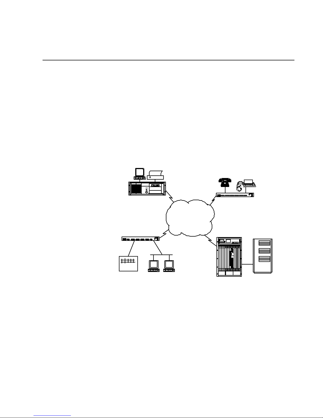
The FRM family shares much f unctionality and compatibility with Cabletron’s Sma rtSwitch 1800, FRX4000, and FRX6000.
FRX6000 with
monitor & printer
SmartSwitch 1800
PBX
Phone
SmartSwitch 1800
Frame Relay
SmartSwitch 9000
Fax
w/FRM
F igure 1-1 Ne twork E xam ple
Eac h FRM is a tw o-slot module that mou nts into a SmartSwitch 9 000. An FRM can
inte ract with other FRM modules , but not with othe r modules in the SmartSwitc h
9000, with the exception of a cable connection f rom each FRM to a LAN interface
module in the SmartSw itc h 9000, which provides LAN connectivit y to the WAN
inter faces o n the FRM.
Eac h FRM with a video interface featur es an intuitive, men u-based manage men t
stru ctur e that allows complete local and rem ote control of othe r FRMs, as well as
SmartS witc h 1800s, FRX4000s , a nd FRX 6000s.
Page 20

Some t ypical FRM applications are:
●
SDLC-to- LLC2 and LL C2-to -QLLC conversio n ov er fram e relay
●
SNA and TCP/IP LAN/WAN in tegr a tion—w ith or without routers
●
B ank ing applicatio ns—LAN, SNA, TCP/IP, async
●
Traffic aggregation and con centration to public fram e relay services
●
"Fr on t end" network to larger frame relay switche s
●
X.25-to-frame relay gateway applications
Multiprotocol Support
E ach FRM suppor ts these rou ting and acc ess pro tocols :
●
Frame Relay
●
X.25
●
SNA/SDLC
●
SNA/LLC2
●
Bridging
●
IP
●
IPX
●
BSC
●
As ync
Management Functions
E a ch FR M su ppor t s the s e m anagement f unct i on s :
●
Lo cal SNMP agen t, with Sets from network manager on some MIB varia bles
●
Manag e a ble via Cable tron’s Spectrum®, SPEL, or Netlink Omni Vie w
●
NetView Service Point function
●
C ontrol via local moni tor, remote FRM, or local/rem ote async terminal
●
File transfer, d atabase backup/resto re, and software updates between dev ices
●
Lo cal conf iguratio n
●
Centralized alarm routing
●
Statis tic s dis play s
●
Line monitor
1-2 Frame Relay Module 4.0 User Guide, Rev 01
Page 21

Hardwar e Overvi ew
An FRM mounts into a SmartSwitch 9000, and connects to an Ethernet or Token Ring
(depen di ng on the model of FRM) module in the chassis via a cable from a LAN
adapter p ort on the FRM. The FRM draws power f rom the chassis , but do es not
inte ract with other SmartSw itch 900 0 modules ex c e pt the LA N inter face module and
other FR M modu l es.
The int ent of the FRM is to provid e the functionality of a 24-port FRX6000 in a
module that occupies two slots in an existing SmartSwitch 9000 (thereby eliminating
the extra sp ace that an FRX6000 would req uire).
Three i960 RISC-based line processors (RLPs) provide the serial interfaces, conne c t ing various synchrono us a nd as ynchron ou s us e r devic es to pu bl i c or pri v at e n et works. Each RLP supports up to seven protocols and up to 1024 simultaneous logi cal
termina tion s. (A link into one physical/logica l port on the RLP and out another port
counts a s two ter minations.)
The following figure shows the basic hard ware components.
An earlier version of the FRM contai ns one RLP, providing eight serial
ports. This manual does not document that ver sion, although all the same
functionality can be found in that FRM except the number of ports.
Each RL P supports eight serial ports,
located on two attached Line In terface
Cards (L ICs). The t ype s of serial ports
depend on the types of LIC, which can
be (in any combination) V.35, RS-232,
or RS-422.
Each FRM also contains:
●
1. 2GB hard disk
●
I/O box/cab le assemblies for
RLP serial p orts
●
Cable for connection to Smar tSwit ch 9000 LAN module
Keyboard Jack
VGA Port
not used
Ethernet Card
RLP
SCSI Connector
for Dis kette Drive
COM Port
Parallel Port
RLP
RLP
Product Overview 1-3
F igure 1-2 Hardware Com ponents
Page 22
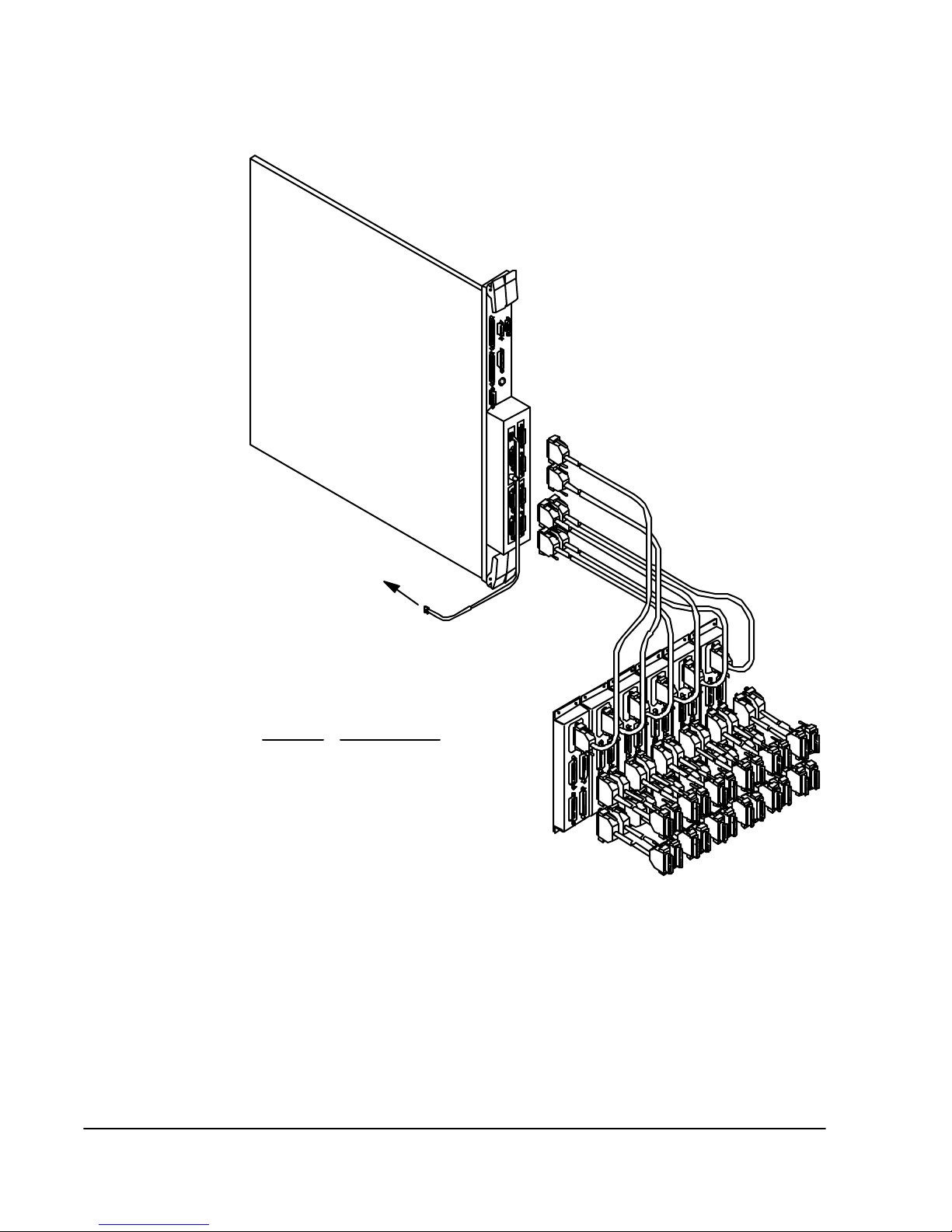
Serial and LAN Interfaces
To LAN
Interface
Module
FRM
Port Type
V.35 V.35 DTE
RS-232 RS-232 DTE
RS-422 RS-449 DTE
I/O Cable Ty pes
V.35 DCE
RS-232 DCE
RS-449 DCE*
X.21 DTE
X.21 DCE
I/O Boxes & Cables
F igure 1-3 FRM w ith I/ O Box es and C abling
As s hown in the figure, each 60-pin serial connector on an FRM supports up to four I/
O p orts, all of the same interface type. A cable carries each connector’s signals to an
I/O box ass embly. The I/O box acts as a "splitter" that carries signals to four 25-pin
connector s. The "final" physical interface dep ends on the com bination of th e type of
I/O cable exiting the I/O box.
The LAN por t on each FRM can be connected to a LAN mo dule in the SmartSwitch
9000 ( as s hown in the fi gure), or to an ex te rnal s our ce.
1-4 Frame Relay Module 4.0 User Guide, Rev 01
Page 23

Operato r Interfaces
Insta lla tion of software into an FRM, generally done before the node ships to the customer, r equi res a direc t ly connect ed keyboa rd and moni tor. Once the n ode has bee n
install ed and configured, it can fu nction with n o op erator interf ace. However, co nfiguration, file copy (backup, restore, transfer, etc.), and monitoring operation s requir e
a keyboard and screen, which can be in any of several forms.
Each FRM is shippe d with c abling to support connection to an ASCII terminal or a PC.
Product Overview 1-5
Page 24

Page 25

Quick Start
Chapter 2
Getting Started
The inst allati on d ocument ation that is shipped with each unit descr i bes th e pro ced ure
for connecting to the FRM from a local or rem ote keyboard an d video d evice. Once
this has been done, the FRM must be customized for the de vices to which it will
connect, the traffic it will rec eive and transmit, and various operating parameters that
can be set to your s pecific needs.
T he ba si c step s you s hould t ake to get the FRM up an d running a re:
1. Read the rem ainder of this chapter, as it exp lains t he user interface on an FRM.
This information will help you understand the menu operations that are neces sa ry
to config ure the FRM for your application.
2. Review the default databa se parameter settings, lis te d in tables throughout
Section II. (A list o f tab les can be found in the Table of Content s.) M any param-
eter s can be left at the d efaul t settings, but some must be recon figured to match
your sp ecific need s.
3. Fill in T abl e 2-1 (on pag e 2-3), to identify the physical interface, protocol, and
co nnected device on each physical port. You will need more information when
configuring database records, bu t these tables can b e used as convenient references.
4. Log into the menu operations, if not already done. This is described in the FRM
Ins tallation & Setup Guide, as well as on page 2-4.
5. Set the corr ect date and time, as described on page 2-9. Event messages, reports,
and some displays include the current date and time as set in the FRM. Th ey
should be accur ate, for pr oper network monito ring an d managemen t.
6. Change the login password, if desired. The default password is
can change this to any pas sword of up to 1 4 char acters, as desc ribed o n pa ge 2-9.
7. Config ure the necessary database reco rds: Node (Chapter 4), SNMP parameters
(Ch apter 16) if SNMP manageme nt will be performed , RLPs and protocols
(C hapt er 5), ne tw ork p or ts ( frame relay – Chapter 7) or X.25 – Chapter 8), plus
LAN interfaces and legacy access ports (miscellaneo us chap ters in Section II).
NETLINK
. You
Page 26
P ort Assign men t Worksheets
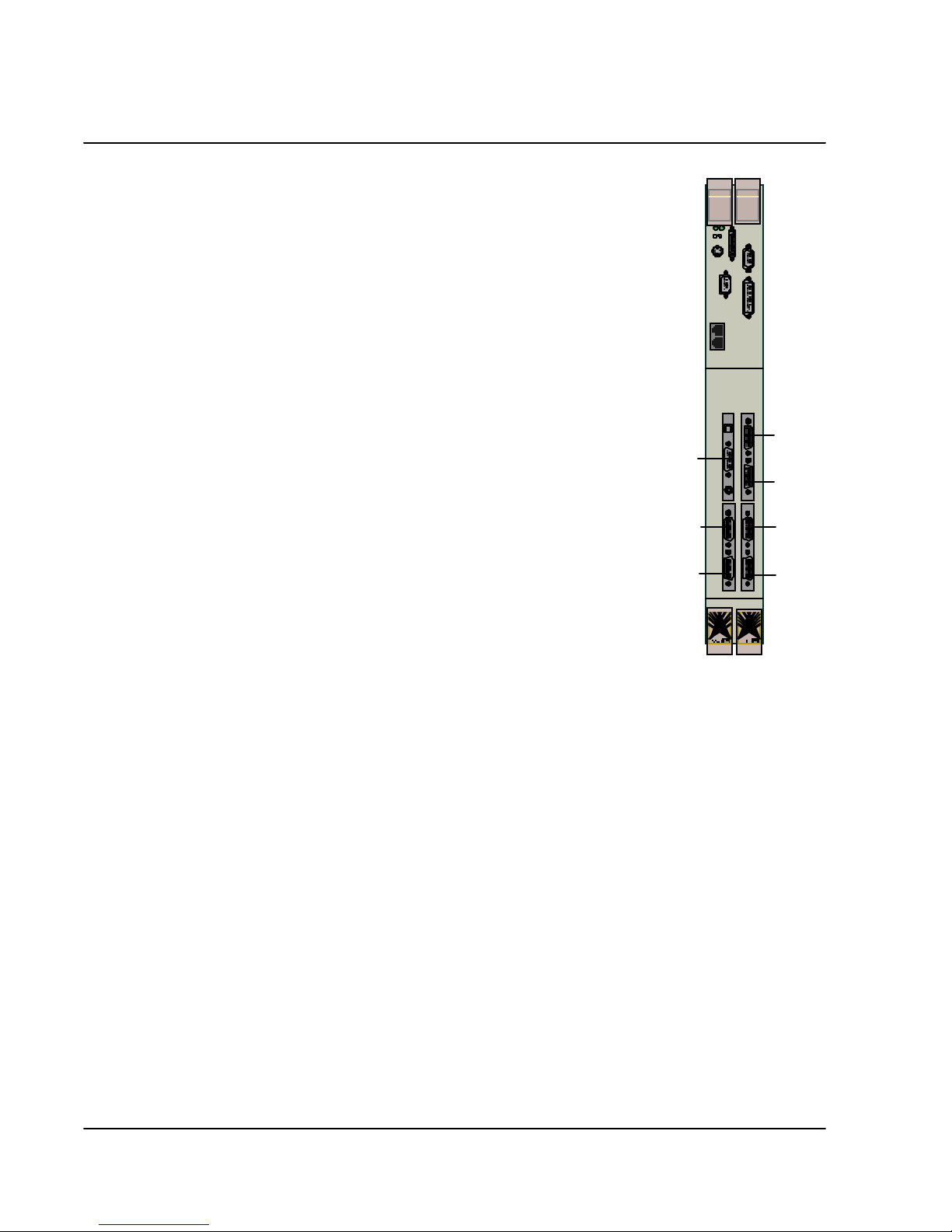
Fig ure 2-1 sh ows the loca tio ns of the Line I nterface Ca rds
(LICs), wh ic h det ermine the types of physical ports supported on the RLP(s).
LIC 1 s upports ports 0–3, and LIC 2 supports ports 4–7.
Note that b ecause the bus ru ns across the FRM above
RLPs 1 and 2, those cards are installed upside down.
LAN 0
LIC 1
RLP 0
LIC 2
LIC 2
RLP 1
LIC 1
LIC 2
RLP 2
LIC 1
F igure 2-1 Li ne Interface Cards
2-2 9W004 4.0 User Gui de, R ev 01
Page 27

Table 2-1 lists all possible phy sical po rts on an FRM.
Table 2-1 Port Assignments
Card Port
Interface
RLP 0 0
1
2
3
4
5
6
7
RLP 1 0 V.35
1V.35
2V.35
3V.35
4V.35
5V.35
6V.35
7V.35
RLP 2 0
1
2
3
4V.35
5V.35
6V.35
7V.35
1
Protocol
2
Co nnected D ev ice
LAN 0 n/a n/ a
1
2
Getting Started 2-3
Physical interface, determined by the LIC an d attached cable. Some LICs are V.35 in all models
of FRM; others differ. Possible interfaces (with LICs in parentheses) are: V.35 (V.35), RS-232
(RS-232), RS-449 (RS-422), and X.21 (RS-422). Each cable is physical DTE (male connector) or
DCE (female connector). Ad d a T or C to the interface type to record this information.
All possible protocols are list ed below:
RLP ports 0–3: Frame relay, X.2 5, SDLC, BSCI (Interactiv e), BSCB (Batch), Async.
LAN port 0: IP, IPX, Bridge, LLC2.
Note that LAN protocols are assigned to physical frame relay ports via interface records that map
the protocols to the physical ports.
Page 28

Lo gging into the Mai n Men u
Configuration (described in Section II) and man a gem ent (Section II I) operatio ns are
access ed via a menu structure, using th e keyboard and video dev ice. Once the FRM
has been conf igure d and i s operationa l, it does not need the keyboard and vi deo
device; however , they are necessary to get the unit up and running.
To protect the FRM fr om unauthorized access, en try to the menu operations requires
a pa s s word.
When running outs ide the menu operations, a display will be similar to the following
figure, and will show the curr e nt status of all ports on the node. (Th is dis play is
described in detail on page 19-2.)
Port Status D isplay (Page 1)
L P Type PPS Conn# State L P Type PPS C onn# State
0 0 FR 62 4 O perational 0 1 SNA 127 12 Operational
0 2 FR 112 7 Operational 0 3 SNA 60 6 Operational
0 4 SNA 110 3 Operational 0 5 X25 87 5 Operational
0 6 SNA 100 8 Operational 0 7 SNA 120 13 Operational
1 0 ASY 0 0 Link_disable 1 1 X25 88 4 Operational
1 2 FR 200 1 Operational 1 3 FR 220 2 Op erational
1 4 SNA 110 3 Operational 1 5 X25 87 5 Operational
1 6 SNA 100 8 Operational 1 7 SNA 120 13 Operational
2 0 ASY 0 0 Link_disable 2 1 X25 88 4 Operational
2 2 FR 200 1 Operational 2 3 FR 220 2 Op erational
2 4 SNA 110 3 Operational 2 5 X25 87 5 Operational
2 6 SNA 100 8 Operational 2 7 SNA 120 13 Operational
0 Eth 0
Node Name=node_xyz
F igure 2-2 Port Status Di splay
No de Na m e
at the upper right dentifies the node under control of the keyboard and screen. This will generally be a directly connected n ode, in
which case the ID will be the
Node Na m e
c onfigure d in the Node Defaults
file (described in Chapter 4). If an operato r takes Rem o t e Cont rol of
ano t he r node ( des c r i be d on pa g e 1 8-1 ) ,
Co nt rol ID
configured in Node Defa ults on the controlled node. Any config-
No de Nam e
will be come the
Remote
uratio n or control operations will af fect tha t node rather than the local one.
I f the controlled node ha s a displ ay scre en, the message
control. Keyboard bl ocked by i d="n"
Remote Control I D
of the controlling node.
will be displayed, wher e "n" is the
Under remote
After the operator presses
page 2-9), the Main Menu (Figure 2-3) will appear .
2-4 9W004 4.0 User Gui de, R ev 01
[F1]
at the screen in Figure 2-2 and enters a pass word (see
Page 29

Version "n.n.n"
M A I N M E N U
A Configuration
B Operations
C Status Displays
D Events
E Statistics
F Reports
Option:
This is the start ing point for all menu operations. The organizatio n of the men us is
sh own i n Appendix E.
Reviewing Boot Messages
Node Name= node_xyzl
F igure 2- 3 Main M enu
As an FRM boots, screen infor matio n tracks the loading of RLP and LAN card
soft ware, verifies conf igu ration file format, and display s any errors. This data is displayed only until the FRM software is running; however, it is sa ved in a file named
BOOTR PT.TXT, and the operator can later display it. This can be used as a tool to
verify that startup of the node proceeded without errors. If there is an error reported,
the data may aid in fixing the problem.
If an FRM is shut down and/or rebooted, the existing BOOTRPT.TXT file will be
renamed BOOTBAK.TXT, an d a new BOOTRPT . T XT will be created. BOOT RPT .TXT
and BOOTBAK.TXT can be us ed as f oll ows:
1. Display and rev iew the data from the “current” boot of the device.
2. Address any reported problems.
3. Re- b oot the device. (This cop ies the previous boot data to a backup file.)
4. Display the new boo t data, and compare it to the previ ou s data. This will s ho w
whether the problem was fixed. Also, a problem that occurred during the previous
boo t-up will often be clear e d up by re-booting.
[C]
To display the data from the c urrent boot-up, press
[C]
from the Main Menu). To display the data f rom the previous boot-up (s aved in a
file called BOOT BAK .T XT), p ress
[D]
at the Reports menu (or
at the Rep orts Men u (or
[F], [D]
from the Main
[F],
then
Menu).
Getting Started 2-5
Page 30

Mov ing Thr ough the Me nus
To select a menu item, pres s the letter to the left of the item .
To return to the next higher menu from a lower-level, press
To move from operations under one Main Menu entry to operations under another
entry, you must return to the Main Menu. The easiest way is to press
until the Main Menu is displ ayed.
Prompts
Within the menu operations, there are two kinds of prompts:
●
Information prompts – respond by typing the req uested information, then
pressing
●
Yes/no prompts – respond by pressing
T hroughout this manual are tabl es of val id and default valu es. T o specif y a defaul t ( if
one exists ), press
[Enter]
.
[Enter]
[Y]
in res ponse to a prompt.
or
[N]
[F3]
.
[F3]
repeatedly
.
On-Line Help
Pressing
[Enter]
when it is not required may cause the next
prompt to automatically select the default choice.
Mo s t s cre en me nus di s pla y a prompt ca lled
Option:
. Pressing
prompt will usually display a list of options. To make a selec tion, pres s either the
function key shown preceding the desired option or the character pr eceding the
desired menu item. The list of options varies, depending on what menu is displayed;
most of t he opt ions are d escribed be low . (Funct i on ke y equi val ents on an async terminal keypad are lis ted on page 2-8.)
F1: Select Another Record
Next Reco rd
—displays the first prompt that appeared on your screen after you
Redisplay/Refresh
or
:
made your menu se le cti on, so you can specify anot her record .
Redisplay/Refresh
F2: Next Record
Next Record
—refresh e s a display with updated information.
Remote Refresh
or
:
—display s the nex t sequen tial recor d on you r screen for verif i cation,
modification, or deletion.
Remote Refresh
—ref r eshes a remote display.
[?]
in respo nse to this
F3: Exit menu
2-6 9W004 4.0 User Gui de, R ev 01
—returns you to t he previous m enu, saving any cha nge s you ha ve ma de.
Some me nus have two sets of values:
Database
C han ges will affect only the database, unless you press
pressing
[F3]
. (This will update the system memory .) Database and
System Memory
and
[F7]
.
before
S ystem memory valu es are des cribed on page 4-3 for No de D efau l t s
and page 6-3 for P orts.
Page 31

F4: Exit menu
or
Delete Record
or
Clear Max Stats
:
Exit Menu
—appears at the Main Men u, and ex its to th e Po r t S ta t us Di spl a y
(Figure 2-2). To return to the menu, you must enter t he node's password. (This
feature is fo r security, to protect menu-level o perations fr om unauthorized
access.)
Delete Record
—initiates the deletion of the displayed record. A record for this
port numb er, conta ining all the default values, w ill remain in the database.
Deleting a port record for an existing port will immediately
disable the port.
Clear Max Stats
fr om the display (rest arting them at the cu rrent values).
F5: Copy Re cord
whi ch can be convenient if sev e ral recor ds in a node will ha ve identi cal (or almost
identical) configurations. After you perform this operation, the "copied to" record will
be displayed, with the new database values. (The original r ecord is automatically
save d. ) Pr ess
—on statist ics displays, clears the maximum/cumulat ive values
—copies a Port record's database values to another port's record,
to updat e th e syste m me mo ry va l u e s .
[F7]
You cannot copy a physical port's r ecord to a logical po rt, or vice
versa.
F6: Move Record
—c opi es a Por t reco rd's dat abase values to anothe r port's reco rd, then
deletes the original record. Af ter you perform this operation, the "moved to" recor d
will be displayed, with the ne w databa se values. (The original record is au toma tica lly
save d. ) Pr ess
to update the system memory values .
[F7]
You cannot move a physical port's record to a logical po rt, or vice
versa.
F7: On-line change
Database
values to
—in Node Defaults or Physical/Lo gical Port config uration , copies
System Memory
. (
Database
and
System Memory
values are
described on page 4-3 for Node De faults and page 6-3 for P o rts .) In IPX a nd Bridg e
Filter Definitions a nd Applications, all changes made on the screen affect only system
memory, so
F9: Stop Remote
must be pressed to update the database.
[F7]
—termina tes a remote control connection, give s you the option of
rebo oting the remote node, and returns contr ol to the loc a l operator.
F10: Abort
Abort
R e boot Re m ote
must then pres s
or
R e boot Re m ote
—initia tes a reboot of a local no de.
—initiates a reb oot of a remote node under local co ntrol. ( You
[F9]
:
to exit remo te control.)
Before aborting or rebooting a node, notify all users that the
node will be going down.
Getting Started 2-7
Page 32

ESC: Quit
—a bando ns t h e c hanges you h ave ma de s in c e t he l a st s a ve (via
and returns you to the previous menu.
[F3]
or
[F7]
)
Character: Select Option
Select Opti on
Change Field
or
Change Field
—appears if an op tion has not yet been s el ected.
—Pr es s the lett er corr espo nding to t he field you want t o chan ge, then
type in the new in formation a nd press
PgUp, PgDn
—a llows you to display multiple screens (one a t a time) for a record, if the
record has more than one.
Function Keys on an ASCII Terminal
Stan dar d PC k eyboard functio n keys are rep resented as fo llows on an AS CII terminal
keyboard. Note that
uppercase letter O.
PC A SCII
Keyboard
[F1] [PF1] ^[OP
[F2] [PF2] ^[OQ
[F3] [PF3] ^[OR
[F4] [PF4] ^[OS
[F5] [5] ^[Ou
[F6] [6] ^[Ov
[F7] [7] ^[Ow
[F9] [,]
[F10] [.]
[PgUp] [–] ^[OA
[PgDn] [–] ^[OB
(under "Maps to:") is an escape character followed by an
^[O
Keyboard Maps to:
(comma)
(period)
^[Ol
^[On
:
[Enter]
.
2-8 9W004 4.0 User Gui de, R ev 01
Page 33

Setting the Date and Time
Various operation s and r eports record the current date an d time, as recognized by the
originatin g d evice. This operation allows ch anging one or both, to assure that all
devices in a network are synchronized.
Press
[B]
at the Node Configu ration Menu (or
[A], [A], [B]
from the Main Menu). The
date and time as currently recognized by the FRM will be displayed , and you will be
asked:
Do you want to change the date?
Press
[Y]
to chang e the date or
[Enter]
to leave
it as is. If changing the date, enter the corr ect information, noting the values in Table
2-2. After the date, change (or leave) the time in the same way as the da te .
Table 2-2 Dat e and Tim e Param et ers
Parameter Valid Value s Default Value
Date Y/N N
Month 1–12 1
Day 1– 31 1
Y ear 1980–2099 1998
Ti me Y/N N
Hour 0–23 0
Minute 0–59 0
Second 0–59 0
Changin g the Login Password
The login password is used to gain access to menu operations. Wh en software is
s hipped to t he c us t om e r, the pas s w or d is
word s are case s ensit ive.)
To chan ge the pas sword, press
[A]
at t he Node Configuration Menu (or
from the Main Menu).
When prompted:
1. Enter the old password.
2. Enter the new password, up to 14 characters (
3. Enter the new password again for verification. If this password is not the sa me as
the entry in step 2, the system will reject the new pass word (and the old one will
remain valid).
Getting Started 2-9
NETLINK
. ( Note the u pper case—all pass-
[A], [A], [A]
A–Z, a–z, 0–9
).
Page 34

S top ping Operation
Logging O ut
Rebooting
Shutting Down
I f you h a ve b e en w o r k i ng with i n m e nu opera t ions and wi sh t o log ou t , press
Main Menu. The Port Status Display screen will be dis played, with an y updates. The
software will continue to run, but only those who know the pa ssword will be able to
gain access to the m enus. You mu st press
the Main Menu.
To reb oot from within the menu level, press
You can not reboot the device from the in itia l Port Status Display. You must
first press
[F1]
an d enter the password to get to the Ma in Menu.
[F1]
a nd enter the password to ge t back into
[F10]
. When ask ed:
Reboot?
[F4]
, press
at the
[Y]
.
Rebooting the device clear s all connections. If you do not want to
do this, simply press
L ocally , an FRM can be reboo te d via the reces sed Res et button lo cated near the top of
the modu le.
An FRM cannot be shut down with ou t powerin g down the SmartSwitch 9000 ;
however, the FRM can be unplugged and removed without disrupting operation of the
SmartSwitch 900 0 or the other modules in the SmartSw itc h 9000.
[F4]
to log out, then leave the device running.
What Next?
Once you a re familiar with the menus and how they work, proceed to Sectio n I I to configure the database.
2-10 9W004 4.0 User Gui de, R ev 01
Page 35

Section II
Configuration
Page 36

Page 37

Chapter 3
Introduction to Database Configuration
Eac h Frame Relay Module conta ins its own configuratio n databa se, which contains
information iden tifying the hardwar e compone nts , and defines the operating par ameters of the har dware and software.
Each database file contains def in ing parameters for a specific co mponent; for
example, physical ports, subscriber IDs, or IP interfaces.
Befo re a n FRM can prop erly operate, all neces sary database par ameter s mu st be configured. The necessary config ura tion depends on the installed hardware, the routing
and access proto cols th at will be used , a nd the devices that will be connected to ports
in the FRM. Some helpful info rmation can be found under "Databas e Setup Recommendations ."
Database Setup Recommendat ions
Many databa se parameters ar e configured with default values, ma ny of which may not
ne e d t o b e cha n ged fo r yo ur co nfigurat i o n. O t h e r parameters , ho w e ve r , defi ne t h e sp ecific co nfiguration. Fo r example, each devi ce must have uniqu e identifiers if the
device will be used in remote control, f ile transf er, or alarm reporting oper ations. Also,
each dev ice will most likely differ in which ports will run whic h protocols , and what
the physical interfaces o n those ports will be.
B efore pr oc eedi ng w it h yo ur confi gu ra t ion, you sh ou l d b e a w ar e o f al l the pa r a met e r s
that mu st b e, or can be, specified. You should first note the d efault v alues, since many
may be correct as is. Tables of parameters, including their valid and default values,
can be fo und throughout S ecti on I I. The Table of Contents conta ins a list of all tab le s.
You should also be familiar with all devices th at will connect to FRM devices; some
have require men ts or restrictio ns.
Some things you must know be fore c onfi gur ing t he da ta base are:
●
The information in Table 2-1 (o n page 2- 3).
●
Addresses that must be specified in various por t and int erface r ecords. Each
X. 25 SVC subscr iber must be as signed an ID (des cribed on pag e 8- 2 1 ) that w ill
be us ed as a calle d or calling address in call setup packets. IP, IPX, LLC2, and
SNMP also requi re addr esses f or iden tificati on of netwo rks and d evices.
●
Passwords. You must enter a password to remotely control another Cabletron
f rame relay acc ess de vice, to perfor m softwa re updates an d file trans fers, an d to
config ure alarm r outing.
Page 38

Most parameters can be specified and/or changed using the operations
des c r i be d th ro ug hout the c on fi g uration p orti on of this manu a l ; ot h e rs , s uch
as RLP and port number, are defin ed by the hardware or specified du ring
s oftwa re installa tion.
C onf ig ur a tion Examples
Legacy Protocols o ver Frame Relay via Logical Ports
Below is a sample config ura tion and guideli nes for config uring Logical Ports for
Annex G or R F C 1490 transmission over f rame re la y.
SDLC
Async
BSCI
X.25
Sync passthru
FRM
Logical Ports
Frame
Relay
FRM
F igure 3-1 Conf i gurat ion E xam ple 1
Configure th e following in each FRM:
●
RLP parameters (C hapter 5 ), to confi gure the RLP( s) that con tain th e ports over
wh ich the protoco ls will run. Each serial protoco l (SNA, async, BSC, X.25,
frame relay) must be configured on the RLP that contains the port.
●
Physical port (Cha pte r 6 plus Chapter 7 [F rame R elay], Cha pt er 8 [X.25],
Chapter 9 [SNA], Chapter 10 [BSCI], and Chapter 12 [Async]).
●
L ogic al port (Chapter 8) on the physical frame relay port that connects to the
network. ( Note that logical ports are numbered 8–63, because 0–7 are the
physical ports.)
●
SVC subscri ber ( Cha p te r 7 [Fram e Relay], C hap te r 8 [X . 25], C hap te r 9 [SNA ] ,
Chapter 10 [BSCI], and Chapter 12 [Async] ) , which assigns static ad dresses
used to route the call request pack ets of the physical access ports to the logical
port an d vice ve rsa. Sub scrib er ad dresses are based on the X.12 1 Called Add ress
fiel d.
●
Op tiona l SVC subscr iber records (s ta tic routes) for any atta ched X.25 DTEs.
The se are needed to identify the attached DTEs’ X.121 Calling Addresses . If an
X.25 Call Req uest is received from th e WAN link, the FRM needs to know
where to route the call.
SDLC
Async
BSCI
X.25
Sync passthru
3-2 Frame Relay Module 4.0 User Guide, Rev 01
Page 39

Frame Relay PVC Passthrough
3174 Control
Unit Running
IP & SNA
Fram e Relay PVC Frame Relay PVC
Figure 3-2 Configuration Example 2
Configure th e following in each FR M:
●
RLP parameters (Chapter 5), to configure the RLP(s) th at contain the fr ame
r e la y po r ts .
●
Ph ysical fr ame re la y port (Ch apter 6 and Chapte r 7). Conf igure the FR M port to
the 3174 as logical DCE, and the po rt to the fram e relay switch as logical DTE.
●
Fr ame r elay PVC (Cha pter 7), which links the two frame rela y ports in the FRM.
The DLCIs are defined in the PVC record; if rate control (CIR, B
enfor ced, be su re to configure those parameters in the fram e relay Por t record.
Make sure each DLCI is supported on the attached dev ice.
LLC2 PUs over Frame Relay to AS/400
FRM
Frame Relay
Switch or
DCE FRAD
, BE) will be
C
AS/400
Local
FRM
Frame
Relay
Remote
FRM
Figure 3-3 Configuration Example 3
Config ure the following in the local FRM:
●
R LP parame t ers (Chapt er 5), to configur e the RLP(s ) that con tai n the ports over
which the protocols will run. Co nfigu re frame relay on the RLP containing the
port to the ne twork. If LLC2 is not already configured in the FR M, configure it
on th e sam e RL P. ( Fram e r elay m ust be conf igured on each RLP that wi ll u se it,
but LL C2 is con figured on on e RLP only. P erfor mance may be enha nced if bot h
proto cols are on th e same RLP, since this eliminates the n eed to communicate
via the bus in the FRM.)
●
LAN Card parameters ( Ch apter 5), to configure the LAN adapter in the FRM.
●
Physical frame relay port (Chapter 6 and Chapter 7).
5494
Introduction to Database Configuration 3-3
Page 40

●
Virtual LAN ID (Chapter 9), which identifies a virtual bridge that connects the
inte rnal LLC2 functio n to the LAN interface.
●
Originated LLC2 Host (Chapter 9), which maps connectiv ity at the LLC lev e l
be twe en the FRM and the AS/400. (The FRM initiate s LLC sessions with the
ho st.) Fo r t hi s exampl e, a ssume t he ho s t n um be r is 0. ( It can be 0 –1 28, bu t i d entifica tion can be easier if the host on the LAN side has the same num ber as the
LAN card number, which is always 0 or 1. )
●
Term inat ed LLC 2 Ho st (Chap ter 9), whose addr es s mus t match the frame rela y
inter face to which th e 5494 device will tra nsmit. N ote that the remote FRM must
have a co rresponding originated L LC2 host. F or this exam ple, assume the host
number is 2.
●
LA N LLC 2 Interfac e (Chapter 9) , which defines an interface to the L AN. For
this example, as sume the inter face number is 0. (I t can be 0–95, but as with the
hosts, identi ficatio n can be easi er if the interf ace on the LA N si de has t he sa me
number as the LAN card number.)
●
Frame relay terminated LL C2 Interface (Chapter 9), which defines an LLC2 ter-
minati on point at the frame relay interface. Be su re to confi gure th e for mat as
8025_SRB or 8023_TB (since the AS/400 needs to see the source MAC
address, which is not passed in the third forma t, Native LLC2). For this
example, assume the interface numb er is 0. Note that the r emote FRM mu st
have a corres ponding origin ated LLC2 Inte rface .
Interface 0
LAN
Local FRM
Host 0
Originated
Host 2
Terminated
Interface 2
Frame Relay
Terminated
Figure 3-4 Local FRM in Configuration Example 3
Some sample L L C2 param eter valu es to configure on the local FRM are:
●
Virtual LAN ID –
●
LLC2 Host 0:
◆
Host MAC Addres s –
007
(hex).
4000000000470
. This is the AS/400 targeted address.
(The 9th and 10th digits of the MAC addres s make up the host number.)
◆
Session Type –
Originated
. This host will initiate the LLC2 session to the
above MAC address.
◆
Routing Subscriber ID –
. T his ID mu st end in an asterisk and con tain
99*
all the digits of the Local Subscri ber ID (shown later in this list).
◆
Source MAC Address Mask –
40000000
. T his is the source MAC address
the FRM will use to se nd frames to the AS/400. The last f our digits are
for the first 57 Host SAPs ( service acces s points) used to connect to the
0000
3-4 Frame Relay Module 4.0 User Guide, Rev 01
Page 41

host. For subsequent SAPs, the last four digits will be incremented to
0002
a frame received from the lo cal LAN.)
◆
Host SAP –
◆
Local Subscriber –
◆
Remote Su bscriber –
◆
Ty pe –
●
LLC2 H o st 2:
◆
Host MAC Addr ess –
(and is th e same as the Host MAC Address con figured o n Host 0).
◆
Se s sion Ty pe –
session to the above MAC add ress.
◆
Rout i ng Subs criber I D –
all the digits of the Local Subscriber ID (shown later in this list).
◆
Host SAP –
◆
Local Subscriber –
◆
Remote Su bscriber –
◆
Ty pe –
0001
, etc. (Each Host SAP ad dress must match the S ource S AP address in
LLC2
LLC2
. (SAP address es can be
04
. This is the Remote Subs cribe r ID of Host 2.
990*
. This is the Local Subscribe r ID of Host 2.
1010*
.
4000000000470
Terminated
. (SAP address es can be
04
990*
. This host will terminate the frame relay LLC2
. This ID must end in a n aster isk and contain
101*
. This is the Remote Subs cribe r ID of Host 2.
. This is the Local Subscribe r ID of Host 2.
1010*
.
. This is the AS/400 targeted address
, hex, in multiples of four.)
04–fe
, hex, in multiples of four.)
04–fe
,
Key Points
MAC Addresses
Interface 2
Frame Relay
Originated
Remo te FRM
Host 2
Originated
Host 0
Terminated
Interface 0
Token Ring
Fig ure 3-5 Remote FRM in Config ur ation Example 3
When entering a h ost MAC address in an LLC2 Host or Interface record, ent er the
addre ss in non -ca nonical form unles s the attached device is o n an 802. 3 LAN and th e
remote device is on an 802.5 LAN, or the attach ed device is on an 802 .5 LAN and the
remote device is on an 80 2.3 LAN. In these cases, the incoming address will be "bitswapped" by the transm itting host, and you must re-swap the bits before tra nsmission
to the remote device. Bit-swap ping is described on page 9-22.
Introduction to Database Configuration 3-5
Page 42

LAN IDs
For referen ce, the following table describes what happ ens to a MAC addr ess at the
FRM if the sending and receiving f o rmats are different.
Ta ble 3-1 MAC Address Conve rsi on
Received from: Forwarded to: Action taken:
802.3 802.5 Converts MAC header to LAN header (including cached
RIF), and b it-swaps address
802.3 Native LLC2 Drops MA C header
802.5 802.3 Coverts LAN header to MAC header, and bit-swaps address
802.5 Native LLC2 Drops LAN header
Native LLC2 802.3 Adds MA C header
Native LLC2 802.5 Adds LAN header (including cached RIF)
LAN IDs can be configured in two places:
●
LLC2 node defaults, to identify a virtual bridge that connects the LLC2 function
to LAN in terfac es.
●
LLC2 frame relay interfaces using 802.5 Sou r ce Route Brid ge format, to
identify the ring number used by a source-route bridge at the remote end. (This
ID is normally assigned by a system administrator.) Note that the LAN ID on an
origina ted LLC2 interface mus t matc h th e LAN ID on the corresp onding te rmina ted interf a ce.
Be aware th at when conf iguring thes e r eco rds, LAN IDs must be entere d in hex . Also
note that, other than th e matchin g IDs on each originated/termin ated interface pair,
each LAN ID mus t be uniqu e within the network on which the FRM will operate .
LLC2 Funct io n
I nternally , L LC2 connects t o interfaces via a vir tual bridg e. LLC2 Host and Int erface
records act as both origin a tion and termination points for LL C2 . For example, if you
are configuring SDL C-to-L LC 2 conversio n to be transmitted over frame relay to a
Token Ring host, the following is the logical LLC2 record flow: SNA Port/PU record
(Chapter 9), with the parameter
LLC2 Connection
set to
. ( This acts as th e both th e
Yes
LLC2 Host and LLC2 Interface termination record). I n additio n, you must configure
an orig inated Ho st for the target MAC address, an d an interface for the physical co nnection.
Terminated LL C Host recor ds always make the calls. Originated LLC Host records
alway s expect to receive calls.
On ly one Origi nate d and one Ter minate d LLC Ho st rec ord can be config ur ed for each
M AC add ress.
3-6 Frame Relay Module 4.0 User Guide, Rev 01
Page 43

RFC1490 Format
An RFC1490 format used for SNA traffic is configured in the frame relay LLC2
Interface/Bridge Port record. The options, in order of lowest overhead to hi ghest
overhead, are:
●
Nat i ve LL C 2 (al so know n as B NN , or Boundary N etwork N ode). Whe n thi s
format is used, no MAC addresses are transmitted across the frame r elay link.
●
802. 5 SRB (source route bri dge) (a l s o known as BAN, or B oundary Ac cess
Node. (FRM devices support BAN type 1). Thi s format is generally used for
3174 gateways and AS/400s, because they need to see a MAC address).
●
802.3 TB (transparent bridge), used when talking to routers that cannot do BAN
or BNN.
Subscriber IDs
Subscriber IDs are only used locally within each FRM to link recor ds (e.g . SDLC PU
recor d to LLC host record), unless the device is runnin g X.25, SDLC/LLC2 prima ry
(the FRM would be SDLC secondary to the FEP), or logical ports (i.e., QLLC), in
whi ch case the subscriber IDs correlate to the static ro utes defin ed in th e subscriber
routing tables.
PU 1 Devices
PU1 d evi ce s can not be def ined as Token Ri ng atta ched to the AS/ 400. AS/400 programmers might try to get around this by defining different device types (i.e., 5494/
PU 2.0 or PU 2.1) to 5294 and 5394 PU1 controllers. However, when this is done, the
ACTPU is not spoofed internally, and is sent to the rem ote controlle r. The FRM
cannot accept and respond, and the controller and AS/400 will go into error mode.
The 53 94 can be RPQed to act as a PU2.1 d evice (see IBM RPQ 8Q0775); 5 294 co ntrollers cannot be RPQed, an d must be attached as SDLC devices; ther e are no issues
with the 5494, as i t is a PU2.0/2.1 node. 5294s and 5394s can only be direct ly c onnected to FRM devices via SDLC or X.25 with speeds up to 64 kbps. 5494s can be
connected via SDLC or frame relay with speeds to 128 kbps, or by Token Ring or
Ethernet/802.3.
3x74s/SDLC over Frame Relay t o SNA Host
Host
FEP/
NCP
Local
FRM
Frame
Relay
Remote
FRM
Figure 3-6 Configuration Example 4
Config ure the following in the local FRM:
●
R LP parame t ers (Chapt er 5), to configur e the RLP(s ) that con tai n the ports over
which the protocols will run. Co nfigu re frame relay on the RLP containing the
port to the networ k, and configure SNA on the RLP containing the port to th e
FEP.
Introduction to Database Configuration 3-7
3X74
Page 44

K ey P oints
LAN IDs
If LLC 2 is not alread y configured in the FRM, configure it on the same RLP .
(Frame relay mu st be configured on each RLP that wil l use it, but LL C2 is con figured on one RLP only. Performance may be enhanced if both protocols are
on the same RLP, since this elimin ates the ne ed to communicate vi a the bus in
the FRM.)
●
Virtual LAN ID (Chapte r 9), which is necessary for LLC2 functio nality .
●
Phy sica l fra m e r e lay po rt (Chap ter 6 an d Chapter 7).
●
Physical S NA port (Chapter 6 and Chapter 9). The link station SDLC/LLC2
co nve rs ion point is also defined in this record, under SNA PU Parame ters.
(These parameters act as both LLC2 Originated Host and Originated Interface
records.)
●
Terminated LLC2 Host (Chapter 9), which points to the frame relay interface.
No te that the remote FR M must have an Originated LLC2 Host.
●
Frame relay terminated LL C2 Interface (Chapter 9), which defines an LLC2 ter-
mination point at the frame relay inter face . Note that the remote FRM must have
an Originated LL C2 Interf ace.
●
SVC subscri ber (C hapter 7), to rou te the incomin g connectio n request from the
fr a me relay LLC2 Termina ted Hos t to the SDLC port. Note that th is reco rd is
not req ui red on the remote FRM, becau se that device originates the connection
(i. e., it is not being called).
LAN IDs can be configured in two places:
●
LLC2 node defaults, to identify a virtual bridge that connects the LLC2 function
to LAN in terfac es.
●
LLC2 frame relay interfaces using 802.5 Sou r ce Route Brid ge format, to
identify the ring number used by a source-route bridge at the remote end. (This
ID is normally assigned by a system administrator.) Note that the LAN ID on an
origina ted LLC2 interface mus t matc h th e LAN ID on the corresp onding te rmina ted interf a ce.
Be aware th at when conf iguring thes e r eco rds, LAN IDs must be entere d in hex . Also
note that, other than th e matchin g IDs on each originated/termin ated interface pair,
each LAN ID mus t be uniqu e within the network on which the FRM will operate .
LLC2 Funct io n
I nternally , L LC2 connects t o interfaces via a vir tual bridg e. LLC2 Host and Int erface
records act as both origin a tion and termination points for LL C2 . For example, if you
are configuring SDL C-to-L LC 2 conversio n to be transmitted over frame relay to a
Token Ring host, the following is the logical LLC2 record flow: SNA Port/PU record
(Chapter 9), with the parameter
LLC2 Host and LLC2 Interface termination record). I n additio n, you must configure
an orig inated Ho st for the target MAC address, an d an interface for the physical co nnection.
Terminated LL C Host recor ds always make the calls. Originated LLC Host records
alway s expect to receive calls.
LLC2 Connection
set to
. ( This acts as th e both th e
Yes
On ly one Origi nate d and one Ter minate d LLC Ho st rec ord can be config ur ed for each
M AC add ress.
3-8 Frame Relay Module 4.0 User Guide, Rev 01
Page 45

RFC1490 Format
An RFC1490 format used for SNA traffic is configured in the frame relay LLC2
Interface/Bridge Port record. The options, in order of lowest overhead to hi ghest
overhead, are:
●
Nat i ve LL C 2 (al so know n as B NN , or Boundary N etwork N ode). Whe n thi s
format is used, no MAC addresses are transmitted across the frame r elay link.
●
802. 5 SRB (source route bri dge) (a l s o known as BAN, or B oundary Ac cess
Node. (FRM devices support BAN type 1). Thi s format is generally used for
3174 gateways and AS/400s, because they need to see a MAC address).
●
802.3 TB (transparent bridge), used when talking to routers that cannot do BAN
or BNN.
Subscriber IDs
Subscriber IDs are only used locally within each FRM to link recor ds (e.g . SDLC PU
recor d to LLC host record), unless the device is runnin g X.25, SDLC/LLC2 prima ry
(the FRM would be SDLC secondary to the FEP), or logical ports (i.e., QLLC), in
whi ch case the subscriber IDs correlate to the static ro utes defin ed in th e subscriber
routing tables.
Producing a C onfigur ation Report
A configuration rep ort con tai ns this informati on:
●
Software versio n num ber
●
Passwords
●
Boot time
●
Various database parameter values
●
Line status for each port
To create a configuration report, press
at the Reports Menu (or
[A]
[F], [A]
from the
M ain Menu). The repor t is cre ated and save d to the node's ha rd di s k unde r th e name
REPORT.TXT.
You can no t generate a configuration report while a file transfer is in
progress.
T o displ ay t he co nfigura t ion r eport , press
at th e Reports Menu (or
[B]
[F], [B]
fro m the
Main Menu).
Introduction to Database Configuration 3-9
Page 46

Where to Find Confi gurat ion Infor mation
The fo llowing shows where to find the va rious configuration files among the menu s.
(The first item,
are the chapters/appendices in this m anual where the items below th ose entries ar e
described. Following most items in the lower tiers are descriptions of the associated
d a t a base r ec ords.
A Configuration
A Configure Node
A–Configuration
A Configure Pas sword
, is an entry on the Main Menu.) Following some items
– ( C hapt er 2) allows cha nging the defa ult login
pas sw ord.
B Configure Time and Date
– (Chapter 2) allows setting a correct time/
date that will be di splaye d on some screens and reports, and will allow
all C abletron frame relay access nodes on a network to be in sync,
regarding reports and alar m messages that include the date and time.
C Configure Node Defaults
– (Chapter 4) specifies IDs and passwords
used for remote co ntrol, file tran sfer, and alarm routing and reporting
operations.
D Configure SNMP Par ameters
– (Chap ter 16) identifies th e SNMP
manager; defines communities; SNMP trap routing , and hardware
platforms (for identif ication by Netlink O mniView elem ent manager ).
A Configure System De fa ults
B Configure Community Table
C Configure Trap Routing
D Configure Mode l Num ber
E Configure IP/LLC2/BRI DG E/IPX Default P arameters
A Configure IP Node Def aults
FRM will act as an IP gateway and which ve rsi on of RIP will be
used.
B Configure Bri dge/LLC-2 Node Defa ults
parameters that will be used internally by the node to iden tif y a
virtual bridge that will connect the LLC2 function to LAN
interfaces and frame relay PVCs.
C Review S NA L LC2 Hosts
– (C hapt er 9) dis pla ys any LLC2 hos t s
(see b elow) that hav e been config ured on the FRM.
D Configure SNA LLC2 Host s
the FRM; includes se ssion type (originated or terminated),
necessary addresses, time rs.
E Configure IPX Node Defaults
th e FRM when used as an inter face to a Novell NetWare
n e twork.
F Configure Filt er De finitions and Applica tions
A Re view I PX Fi lter De finitions
filters (see next item) that ar e configured on the FRM.
B Configure IPX Filter Definiti ons
parame te rs for tr ansmission of RIP and SAP updat es, a nd/or
generic IPX packets, per interface and direction.
C Review IPX Filter Applicat ions
information on any IPX filter applications (see below)
config ured on the FRM.
D Configure IPX Filter Applications
filters to interfaces/filter types/directions.
– (Chapter 13) specifies whether the
– (Chapter 9) specifies
– (Chapter 9) defines LLC2 hosts on
– (Cha pte r 14) defines operation of
– (Chapter 14) displays any IPX
– (Chapter 14) specifies
– (Chapter 14) displays
– (Cha pte r 14) applie s IPX
3-10 Frame Relay Module 4.0 User Guide, Rev 01
Page 47

E On-Line Update IPX Filter Def initions and Appl icat i ons
(C hapt er 14) al l o w s up datin g t he FR M w i t h an y c hange s
without rebooting.
F Re view Bridge Fi lter De fi ni ti ons
Bridge fil ters (see next ite m) t hat have bee n confi gured on the
FR M.
G Con figur e Bridge Filt er Defi nitions
param eters for regulatio n of bridge traff ic by filtering MAC
addr e sses, NetBIOS na mes, SA P updates, e t c.
H Re view Bridge Fi lter Applications
information on any bridge filte r applications ( see below)
co nf igur e d on the F RM.
I Con figur e Bridge Filt er Appli ca tions
bridge filte rs to interfaces/filter types/directions.
J On-Line Update Bridge Fi lter De fi ni ti ons and Appl i ca tions
(C hapt er 15) al l o w s up datin g t he FR M w i t h an y c hange s
without rebooting.
G On-Line Update Dynamic Routing Parameter s
the system mem ory with any changes that have been made to
routing parameters.
F Con f ig ur e Async P AD Param eters
parameters for devices connected to FRM async PAD p orts.
A Review Asy nc P AD Pro fi les
B Configur e Asyn c P AD Profiles
C Re view Async PAD Logins
D Configur e Async PAD Logins
G Review M odel Information
– displ ays the ma ximum number of
logical con nections allowed , a nd lists the protoc ols installed, on the
RLPs.
H Configur e Bandw idth Allocation G r oups
to 16 groups that assign connection priorities to va rious types of
traffic.
B Configur e RLPs
A Rev iew RLP Configuration
(Chapter 5)
– displays installed protocols and
identifies installed Line Interf ace Cards.
B Configur e RLP
C Display RLP Memory S tatus
– allows installing and removing protocols.
– displays a ta ble s howing a vaila ble and
used memory on each RLP.
C Configur e Por ts
A Configur e RLP Po r ts
– (Chapter 6 through Chapter 12) specifies each
serial po rt's ty pe, physical interface, and operating parameters.
B Configur e LAN Ports
– (Chapter 5) specifies an ass ociated MAC
addr ess for the LAN interface.
C X.2 5 A dd r es s T ra n slati o n Te mp late s
and tests templates that ar e applied to incoming and outgo ing call
packets for the p urpos e of trans lating select ed fiel ds of a packet that may
not otherwis e be in a c ompatible format.
A Review X.25 Address Translation Templates
B Configur e X.25 Addr es s Tra nslation Templates
C Test X.25 Address Transl ation Te m plates
D Configur e Logical Ports
– (Chapter 8) specifies operating par ameters
for logical ports residing on physical frame relay ports.
E Configur e IP/L LC 2/B RIDGE/IP X In ter faces
–
– (Chapter 15) displays any
– (Chapter 15) specifies
– ( C hapt er 15) dis pla ys
– (Chapter 15) appl ie s
– ( misc. ) updat es
– ( C hapt er 1 2) defi nes opera ting
– (Chapte r 7) defines up
– (Chapter 8) displays, specifies,
Introduction to Database Configuration 3-11
Page 48

A Review IP Inte rfaces
– (Chapter 13) displays information on any
IP interfaces (see below) configured in th e FRM.
B Configure IPII nte r faces
– (Chapter 13) specifies add ressing and
operating parameters for IP interfaces (X.25, fram e relay, o r LAN).
C Review Br i dge Por ts / LLC 2 Interfaces
Chap ter 15 [Bridge]) displays information o n any bridge or LLC2
interfaces (see belo w) configured in the FRM.
D Configure Bri dge Por ts / LLC2 In t erfaces
Chap ter 15 [Bridge]) specifies location, type, and format of any
brid ge or LLC2 in terf aces.
E Review IPX Interface s
– (Chapter 1 4) displays in formation on
any IPX interfaces ( see below) configured in the FRM.
F Configure IPX Interfaces
– (Chapte r 14) identifies any IPX
interfaces. Identifies type ( X.25, Ethernet, etc.) and operating
parameters.
F Configure BS C Device s
A Review BSC De vi ce Configu ration
(C hapt er 10)
BSC Interactive device s (see bel ow) configur ed in the FRM.
B Configure BS C Devi ces
– identifies devices using FRM ports
config ured as BSC Interactive.
G Review LAN Card Configuration
– (Chapter 5) displays information on
the LAN car d.
D Configure Conne ctions and Routing P aths
A R eview Su bscri ber ID s
– (misc. chapters) displays information on
any s ubscriber IDs (see b elow) co nfigured in the FRM.
B Configure Subscriber IDs
– (misc. ch ap ters) id entifies end user d ev ices
sending/re ceiving traff ic over to logical X.25 ports on the FRM, and
specifies parameters f or redirectin g this traffic to other ports.
C Re view Abbreviate d Addr esse s
– (Chapte r 12) display s inf orm at i on
on an y abbreviated addresses (see b elow) configured in the FRM.
D Configure Abbreviated Addr es ses
– (Ch apter 12 ) specifies short
versions of subscr ib er IDs that can be used in p lace of the full
address es for async PAD subscribers.
E PVC Configuration
– (Cha pt er 7 [frame relay], C hapter 8 [X.25],
Ch ap ter 1 2 [async]) displays/specifies "permanent" connections
between FRM ports.
A Review P VC Configuration
B Configure PVCs
F Review IP Routing
– ( C hapt er 13) dis pla ys informa tion on a ny IP
routes (see belo w) configured in the FRM.
G Configure IP Routing
– ( Ch a pter 13) define s r oute s fo r IP t ra ff i c
through the FRM.
H R eview IPX Routing
– (Chapte r 14) display s inf orm at i on on any IPX
routes (see belo w) configured in the FRM.
I Configure IPX Routing
– (Chapter 14) defines routes for IPX traffic
through the FRM.
E Configure Fr ame Relay Backup Groups
– (C hapt er 7) al low s creat ion of
one o r more frame relay ports/DLCIs th at wi ll act as back up(s) for a
port.
A Review Frame Re lay Backup Groups
B Configure Frame Relay Backup Gro ups
– (C hapte r 9 [L LC 2],
– ( C hapt er 9 [ LLC2],
– displays information on any
3-12 Frame Relay Module 4.0 User Guide, Rev 01
Page 49

Node Defaults
Chapter 4
Configuring Node-Wide Default Parameters
Node Defaul ts are a s e t of parameters that identify an FRM for purposes of remote
contr ol, softwar e update s, file transfers , and/or alarm reporting to or from a remote
FRM, SmartSwitch 1800, FRX4000, or FRX6000. The Node Defaults file also contain s information tha t defines a connection to a NetView manager device.
[C]
Press
This is th e first o f three Node Defaults scree ns—pressing
the display among th e three screens.
The first two screens contain parameters that apply to all users. The third screen contain s parameters used in sessions between a NetView host and the NetView service
poin t function in the FR M . If the NetView functio n will not be used , the third scre e n
doe s not ha ve to be confi gured.
at the Node Configu ration Menu to display a screen simi lar to Figure 4-1.
[PgDn]
or
[PgUp]
will change
Node Defaults C onfiguration (Sc r een 1 of 3)
Database System Memor y
A Node Name node_xyz node_xyz
B Remote Control ID
C Remote Control Pwd
D F il e T r a ns fer I D
E F ile Trans fer Pwd
F Collecting FRM ID
G Co l l ec t i n g FR M Pw d
H Primary A larm Output ID
I Pr imary Alarm Output Pwd
J Se c o nda r y Al a rm Ou t put ID
K Sec o nda r y Al a rm Ou t put P wd
Op tion:
Node N ame=node_xyz
Figure 4-1 Node Def aults C onfigurat i on Sc reen 1
[A],[A],[C]
from Main Menu
Page 50

After making any changes, be sure to press
[F7]
to update the
system memory. Otherwise, the changes will not take effect until
the next re-boot of the FRM.
Although the entries for the various passwords appear blank,
default values exist; if you change one, be sure you do not
duplicate an existing password.
Warning Messages
One of the following messages will be displayed if there is a problem with the configuration for event (alarm) reportin g.
Primary Al arm Reporting Err or
appears at the top of all screens on a collecting node if the software that d ri ves the
alarm output device is unable to o utput to the device.
Primary NOT Configured
appears at the bottom of both Node Defaults screens if a
sp ecified .
Primary/Secondary C/P"n" NOT installed
appears at the bottom of both Node Defaults scre ens if a s e rial (C) or parallel (P) po rt
is s pecif ied for th e
is either incorrectly configured or is not installed. For a serial port, this message will
also be dis play ed if the car d is properly installed but the dev ic e at th e other en d is not.
Primary/Secondary Printer/Connection Problem
appears at the bottom of both screens if a parallel (P) port is speci fied and the card co ntaining the port is installed but the de vice at the other end is not. Note that this will not
be deter mine d by the software until the first alarm is sent to the parallel port.
Primary Output ID
and
Second ary Output ID
allel po rts. If a serial po rt is specified, no associated pas sword (
can be address es, or serial/par -
) entry
Pwd
will b e displayed for the ID. Instead, a group of operating pa rame te rs
(listed in Tabl e 4 -1 ) for the port will be displayed.
is not
Primary/Secondary Alarm Output ID
Primary A larm Output ID
, but the car d contain ing t he port
Primary/Secondary C/P"n" NOT Initialized
appears at the bottom of all b oth screen s if a serial or parallel po rt is specified, but
eith er the soft ware canno t f ind the sp ecified port or it is in use fo r some other purpo se.
Errmsg.txt Database Error
appe ars if the f ile ERRM SG.TXT c an not be found. (This may ha ppen if a s oftware
update was not correctly ins talled.) To correct this, the file c an be created with the f ollowing procedure:
1. Press
[F10]
2. Wh en asked :
3. As the node starts t o boot, press
4. Wh en asked :
5. At the DO S pr ompt, type
6. To re sta rt the FRM, type
4-2 Frame Relay Module 4.0 User Guide, Rev 01
at the Main Men u.
R e boot t he node?
Terminate batch job?
generr.exe [Enter]
omni4 [Enter]
, press
[Ctrl] [C]
, pres s
[Y]
.
.
.
[Y]
.
.
Page 51

Database and System Memory V alues
Two sets of values exist for Node Defa ults paramete rs : Databa se values exist in the
soft ware, an d are recorded as S ystem Mem ory values when the node is booted. If the
port type is the same in both sets of values, both se ts w ill be displayed.
Any change you ma ke will be recorded a s a D atabase value, and will be copied to the
System Memory side only if you press
save d to the da ta base until you press
Node Defaults Parameters
All possible parameters on the first two Node Defaults screens are listed in Tab le 4-1,
and the NetView para meter s on the third screen are lis ted in Tabl e 4- 2 (on page 4-7).
Depending on the values configured for some parameters, other parameters might not
be displayed.
Descriptions of most parameters follow each table.
Table 4-1 No de Defau lts Parame te rs
Parameter Valid Value s Default Value
Node Name
Remote Control ID
Remote Control Pwd
Fi le Tr an sf er I D
Fi le Tr an sf er Pw d
C ollecting Node ID
C ollecting Node Pwd
Primary Alarm Output ID
Primary Alarm Output Pwd
Secondary Alarm Out put ID
Sec ondary Al arm Output Pwd
Com. Port Thruput A–H
Com. Port Parity 0, 1, 3
Com. Port Stopbit 1, 2 1
Bits per Cha rac ter 7, 8 8
C ollecting Node Y/N N
M ax Congestion
Min Congestion
Periodic Stat us Timer 0–30
Line Idle Timer 0–65535
Alarm Autocall Timer 5–3600
Ala rm Ma x Retri es 0–99
Remember that the software sees uppercase as different from lowercase.
1
[F7]
. Note that cha nges will not be actually be
[F3]
to exit the record.
up to 8 characters none
0–15 digits none
0–15 characters
1
remote
0–15 digits none
0–15 characters
1
ftran
0–15 digits none
3
(sec)
1
2
1
2
1
alarms
none
alarms
none
alarms
H
(9600 bps)
0
(none)
50
25
1
4
0
60
0
(no max)
0–15 characters
see footnote
0–15 characters
see footnote
0–15 characters
1–50
(%)
1–50
(%)
(min)
(sec)
5
Co nfiguring Node-Wi de Default Parameters 4-3
Page 52

Can be:
2
A value of
3
If 0, t he connection will remain active continuously.
4
Continuous retries until connection is established.
5
The parameter
6
parameter on one screen will automatically change it on the others.
Node Name
is dis played at the u pper right of the scr een when the device is being contro lled by the
"local" keyboard and monitor. (If the local ope rator is co ntrolling a remote device, the
Remote Control ID
Remo te Control ID
is r equired if a remote node or async ter minal will be used to take control of the local
FRM (via a physic al or logical port in the lo cal device). The ID will be checked agains t
the called address fields of inco ming Call Requests. The rem o te device can be a terminal connected to an async PAD port on a remote node, or the remote node itself.
Make sure that each FRM, SmartSwitch 1800, and FRX4/6000
on the same network is assigned a different Remote Control ID.
a 1–15 digit number (address).
◆
a COM port:
◆
a parallel (LPT) port:
◆
0
or C2, pl us
C1
P 1, P2, P3.
means tha t no status wi ll be sent.
On-Line Temporary Changes
of that de vice will be displayed a s the local
C3
or
if those po rts exist.
C4
appears on all th ree screens; chan ging this
No de Na m e
.)
Remote Co n tr ol Pwd
is a password used in conjunc tion with the
against the user data f ield of a C all Request p acket. Both the
the password must match what is expected, or the FRM will not accept a request for
remote control.
File Transfe r ID
is use d for file tran sf ers (see page 18-4) to or from this FR M. The ID will be checked
against the called address field of a Call Request p ackets coming into this FRM .
File Transfe r Pwd
is a password used in conjunc tion with the
and the
File Transfer Pwd
request for file transf er .
Collecti ng Node ID
is defined on a collecting node (described later) for use by other FRM, Sm artSwitch
1800s, and/or FRXs that send their alarms to that collecting node. Th is same ID must
be con figured on each non-collecting node as th e
lecting Node ID
Collecti ng Node Pwd
is a password that will be checked to verify that the
us ed for alar ms. Since th e same ID can be spec ified for sev eral functio ns, th e softwar e
processes can use the pas swords to ide ntify the different functio ns.
Remote Control ID
File Tr ansfer ID
must matc h what is expected, or the FRM will not accept a
Primary Alarm Output ID
has no function on non-collect ing nodes.
Primary Alarm Output ID
, an d will be checked
Remote Control ID
. Both the
File Transfer ID
. Th e
and
Col-
is being
4-4 Frame Relay Module 4.0 User Guide, Rev 01
Page 53

Any non-alarm passwords must be different than any alarm
passwords. Unless you are certain you are not duplicating a
password, leave all passwords at the default settings.
Primary Alarm Output ID
spec ifies where alarms will be sent. On a devic e configured as a collecting node , the
ID is usually associated with a printer port (serial, parallel, or asyn c PAD port); on
non-collecting nodes, the ID is usually the
node. The alarm system is designed for guaranteed delivery to the primary output
device, an d output to the secondary device only if it is available. Problem s with the
seco ndary device will not s top delivery to the primary device.
I f sp ecif ying an async po rt to a prin ter, be sure to co nfigure t he async PA D
profile (see page 12-2) to match the line speed of the printe r . (Do not con-
figure the port for
Primary Alarm Outp ut Pwd
is a password that will be used with the
lecting node, the local FRM's
coll ecting node ’s
Secondary Ala rm Output ID
is used for a collecting node to send alarms to a second location other than that specified by the
nodes.
Collecting Node Pwd
Primary Alarm Output ID
Primary Al arm Output ID
Autobaud
Primary Al arm Output Pwd
.)
Primary Alarm Output I D
(P assword) must m atch the
o f a collecting
. If that ID is a col-
.
. This parameter has no function on non-collecting
Secondary Ala rm Output Pwd
is a password that will be used if the
also associated with a password. If so, both passwor ds must match.
Com. P or t Thruput
is the line speed (in bits per second) through the COM port:
= 11 0 b ps
A
= 1200 bps
E
Com. Port Parity
= 150 bps
B
= 2400 bps
F
sets the pa ri ty bit, which is used to detect c han ges in bit structure of the data from
origin to destin ation :
Com. P or t Stopbit
sets 1 or 2 stopbi ts, wh ich signal the end of a character.
Bits per Charac ter
sets the bit value at 7 or 8 per cha racter.
Collecting No de
is an FRM to which alarms are sent from other FRM, SmartSwitch 1800s, and/or
FRXs. A ny of the s e node types ca n be a collec ting node ; which node s s end t heir
alar ms to a collectin g nod e is determined by the
words of the other nodes; these must match the
thei r collecting nod e.
Secondary Alarm Output ID
= 300 bps
C
= 4800 bps
G
= N one ,1 = Odd,3 = Even.
0
Primary Alarm Output ID
Collecting No de ID
= 600 bps
D
= 9600 bps
H
is an addres s that is
s and pass-
and pas sw ord of
Co nfiguring Node-Wi de Default Parameters 4-5
Page 54

The number of nodes that can report to a collecting node depends on the number of
connections that can exist on the colle c ting no de. (An FRM supports up to 512 connections per RLP.) A connection on a collecting node is required fo r each r eporting
device.
Do not configure a collecting node to send its alarms to another
collecting node. The alarms will be ignored, due to a format mismatch.
Max Cong esti on
is a per centage of th e FRM alar m buffer. I f this level is ex ceeded , no mor e a larms will
be put into the buffer until it has reached the specified
below and "Alarm Buffer" on page 21-2.)
Min Congest ion
is a percentage of the FRM alarm buffer. As long as the percent of the buffer that is
full is belo w this level, alarms will always be placed into the buffer. (Se e "Alar m
Buffer" on page 21-2.)
Periodic Status Timer
sets the frequency with which the FRM will send a "heartbeat" alar m message containing the date and time. The heartbeat serve s as a verification that the FRM is operational.
Min Congestion
. ( Se e that entry
Line Idle Timer
is a perio d that an SVC alarm conn ection wi ll re main activ e after an ala rm mess ag e is
sent. I f no alarm is generated during this time, the alarm con nection is cleared. The
Periodic Status Timer
status messages for this FRM will be sent. On a repo rt ing (non-coll ecting) node, it is
generally pref erable to set the
, to give the system a chance to upd ate itself. The timer is usually set to 0 on a
Timer
collecting node .
The
Li ne Idle Tim e r
Alarm Autocall Timer
specifies the frequency with which the FRM will attempt to establis h an alarm connection with its
alar m connectio n is c leared .
Alarm Max Retr ies
is the number of times the FRM will attempt to establish an alarm connection with its
Primary Alarm Outp ut ID
is clear ed .
If the value specified is gr eater than
maximum retry value is reached. If the connection is still not establis hed, a retry will
be made once eve ry hour.
(see that entry) determin es the frequency with which routine
Li ne Id le T imer
i s also affected by the v alue of
Primary Alarm Output ID
to a perio d long er th an the
Max Congestion
Periodic Status
.
during initial call setup or after the previous
during initial call setup or after the previous alar m co nnection
, the
0
Alarm Au tocall Timer
will be used until the
4-6 Frame Relay Module 4.0 User Guide, Rev 01
Page 55

Ne t V iew Par ameters
Parameter V alid V alues Default Value
Name
Local Sub scr iber ID
Remote Subscriber ID
Maximum Bytes per Frame 25–4105 265
Local SAP Address 0–fc
Local MAC Address 0–ffffffffffff 000000000000
IDBLK 0–fff 000
IDNUM 0–fffff 00000
T1 0–250
T2 100–5000
Ti 1–50
N3 1–127 1
Tw 1–127 1
N2 0–255 8
Priority 0–9 0
Ba ndw idth Allocation G roup 1–16 1
1
2
3
4
Table 4-2 NetView Parameters
3
(msec)
1
4
none
04
10
100
30
2
(1 sec)
up to 8 characters
0–15 characters none
0–15 characters none
(hex)
(x 100 msec)
(sec)
Up to 10 characters can be entered, but on ly the first 8 will be recognized by NetView.
Be aware that some NVMTs are larger than 265 bytes, so you may want to set the value
higher.
In multiples of 4.
Must be less t han the value for T1 to ensure that the remote link station will receive the
delayed acknowledgment before T1 expires.
Name
is the VTAM PU name that will identify the FRM as a N etV ie w Se rvic e Poin t.
Local S ubsc r i ber I D
is a subscrib er address for the local en d of an LLC2 sessi on e stabl ished f or a NetView
connection. An LLC2 Hos t r ecord (see pag e 9-19) must be created, with
Type = Term inated
and the same
Local Subscriber ID
and
Remote Subscriber ID
Session
as spec-
ified here in the NetView parameters .
Remote Subscriber ID
is a subscr iber address for the remote end of an L LC2 sess ion established for a
NetView connection . An LLC2 Host reco rd (see p age 9-19) must be created, wi th
Session Type = Originated, Local Sub scriber ID
here in the NetView parameter s, and
Remote Subscriber ID
= th e
Remote Subscriber I D
= the
Local Sub scriber ID
specified
spec ified in the NetView paramete rs.
Maximum Bytes pe r Frame
must correspond to the PIU size configured on the NetView h ost (parameter
MAXDATA of macro PU in VT AM).
Co nfiguring Node-Wi de Default Parameters 4-7
Page 56

Local SA P Address
is a service access point (SAP) ad dress used to identify th e FRM to a NetView host.
This parameter is relevant only in a connection to a 3174 or AS/400-type setup whe re
a specific source SA P a ddress is required. If the session will be run over a native LLC2
frame relay interface, the parameter wi ll be ignored.
Loc al MAC Addres s
identifies the local FRM to a NetView host. Like th e local SAP address, this parameter
is relevant onl y in a con nect ion to a 3 174 or AS/ 400 -type s etup wh ere a sp ecific s ource
MAC address is required. If the session will be run over a native LLC2 frame relay
interface, the parameter will be ignored.
IDBLK
is used in conjunc tion w ith
(format 0 or 3) to establish a link station connection to the host. A further explanation
is provided under "
IDNUM
is used in conjuction with
0 or 3) to establish a link station connection to the host. If
and
, the Node field of the XID will be provide d by the attached device. (The
IDNUM
node will send an XID command to the remote node to indicate that the device should
be poll ed for an XID.)
T1
is the Rep ly Timer, which is us e d to detect the failure to receive a re qu ired acknow ledgment or response from the re mote link station. The link station will start the timer
when it transmits o ne of these:
IDNUM
in gen eratin g the Node field in an XID frame
IDNUM
."
in g enerat ing the No de fi eld in an XI D frame (fo rm at
ID BLK
is sp eci f ie d fo r bo th
0
IDBLK
●
an Information LPDU (LLC protocol data unit).
●
a Command LPDU with the P bit set to B'1.' (If this LPDU is sent while the timer
is already running , the link station will reset and restart it.)
The link station will reset
●
A REJ (Reject) LPDU, provided a Command LPDU with P bit set to B'1' is not
when it r eceives one of these:
T1
outs ta nd ing.
●
A Res ponse LPD U with the F bit set to B '1.'
●
A n Informa tion or Su pe rvi sory LPD U wi th an N(R) greater than the last N(R)
received an d less than or equ al to the line station's V(
LPDU with P bit set to
' is not outstanding.
B'1
), provided a C ommand
S
If additional LPDUs are set from the remote link sta tion a fter the local station has reset
, the timer will be restarted if acknowledgments of or responses to those LPDUs are
T1
outstanding. If no acknowledgments/responses are outsta nding , the link station will
start the inactivity timer. (See "
expir es and acknowledgme nts/resp on ses are stil l outstanding , the link station
If
T1
will send one o f the following, then restart
●
A Su pervisory LPDU with the P bit set to
Ti
.")
T1
:
(to solicit remote link station
B'1'
status).
●
An y Unnumbered LPDUs that wer e not responded to the first time they were
sent.
4-8 Frame Relay Module 4.0 User Guide, Rev 01
Page 57

If acknowledgme nts/responses are still outstanding after N2 tries, the link s ta tion will
declare the link inoperat ive.
T2
Ti
N3
The value specified for
should allow for an y delays intro duced by the MAC s ub -
T1
laye r (e .g., queuing).
is the Receiver Acknowled gme nt Timer, used by the lin k station to delay sending an
acknowledgment of a received I nformation LPDU. The timer is started when the
LPDU is received and reset when the ack nowledgment is sent. If the timer expi res
before the acknowledgment is sent, it must be sent as soon as possible.
is the Inactivity Timer, used by the link statio n to detec t an inoperative conditio n in
eith er the remote link statio n or the tra nsmission medium. The timer will be starte d if
T1 h as been reset (for one of the reasons listed under "
") , and additi onal LP DUs
T1
have been sent by the remote link station, and there are no outstanding acknowledgments or respons es from the local link station.
If the local station does not receive an LPDU b efore
an LPDU with the P bit set to
proceeds as described under "
' to s olicit the remote station's status. Recovery then
B'1
."
T1
expires, t he st a t i on must sen d
Ti
is the number of Informatio n LPDUs that will be receive d bef ore sendin g an acknowledgment. This parameter is used in conjunction with
to allow stations to reduce
T2
traffic. A counter is initialized to N3, and will be decremented by one each time a v alid
sequential I n formation LPDU is received. When the counter reaches
an ackn owl-
0
edgment is sent.
is reset w h e n eve r a n Info rmat i on or Supervis ory ackn ow l edgm e nt L PD U is sent b y
N3
the local station.
Tw
is the maximum number of sequentially nu mbered Information LPDUs that the link
station can have outstanding .
N2
is the maximum number of times that an LPDU (including Information LPDUs resent
after a checkpoint ope ration) will be sent following expiration of
Prio rity
priorit izes NetView traffic among all intra-no dal traffic ; the higher the number, the
high er the priorit y. (This priority ha s no effect on traffic exiting an FRM.)
Priorities are conf igured on all logical interfaces that use a physical fr am e relay port.
The device processor in the node uses the se priorities to help det ermine the order in
which it will process protocols.
Bandwidth Allocation Group
assi gns NetView session s to one of sixteen groups whose para meter s regulate ban dwidth usage. See "Confi guring Ba ndwidt h Alloc ation G roups " on page 7-6.
T1
.
Co nfiguring Node-Wi de Default Parameters 4-9
Page 58

Page 59

Configuring Cards and Protocols
The circuitr y that supports the serial I/ O ports resides on
three RL Ps (RI SC-b ased lin e proces sor car ds), and on two
four-port L ine Inter f ace Car ds (LI Cs) mounted on each
RLP.
Because the bus run s across the FR M above
the bot t om ro w of ca rds , RLP s 1 and RLP 2
are in st all ed u psi de down .
LIC 1 supports ports 0–3, and LIC 2 supports ports 4–7.
The types of serial ports depend on the model. (All four
po rts o n a LIC are th e same.)
Chapter 5
An earlier version of th e FRM contains one
RLP, providing eight serial ports. This manual
does not document that version, althoug h all
the same functionality can be found in that
FRM except the nu mber of ports. The RLP in
that FRM is also instal led upside down .
Figure 5-1 Line Interface C ards
LAN 0
LIC 2
RLP 1
LIC 1
LIC 1
RLP 0
LIC 2
LIC 2
RLP 2
LIC 1
Page 60

R LP and Protoco ls
The RLP file c onta ins the information shown in Figure 5-2 for each RLP. To access
the RLP scr eens, pr ess
To displ ay a table of me mory us age, press
information , in conjuctio n with information in the re le ase no tes, can help in planning
the number of protocols to run.
[A]
, then
[B]
fr om the Mai n Menu.
[C]
at the RLP Configur at ion Menu. This
To configure a protocol, press
RLP number
for an
* RLP: 0 * Statu s: Installed * M e mory Configuration: 8 Meg
* RLP Type : R LP
* Line Interface Card 1: V.35
* Line Interface Card 2: V.35
F Protocol 1: X.25 X.25
G Protocol 2: FRL F RL
H Protocol 3: Async Async
I P rotocol 4: SDLC SDLC
J Protocol 5: IP IP
K Protocol 6: None
L Protocol 7: None
M Protocol 8: None
N Pr otocol 9: None
O ption:
(see Figure 5-1), type a number :
RLP Configuration
Configured Loaded
F ig ur e 5-2 RL P Co nf igur at ion Me nu
[B]
at the RLP Configuration Menu. When prompted
0–2
Nod e Name =nodexyz
[ A], [B],[B ]
, th en press
from Main Menu
[Enter]
.
To add or remove a protocol, press the letter corresponding to the protocol number.
Th e protocol in the
(See Table 5-1.)
After all desired changes have been made, press
the FRM as follows:
Rebooting will clear all connections on this device. However, the
device must be rebooted to implement the change.
1. Press
2. Wh en asked :
3. Type
5-2 Frame Relay Module 4.0 User Guide, Rev 01
[F10]
restart [Enter]
Configured
.
R e boot t he Node?
.
colum n will change to the nex t valid one.
[F3]
to save the changes, then reboot
[Y]
, press
.
Page 61

RLP Pa rame ters
Protocol
Table 5-1 RL P Parame ters
Para me ter Vali d Valu es Defa u l t Value
Pr otocol "n" None , X.25, Fr ame Rela y, Asy nc,
SDLC, BSC-I, BSC-B, IP, SNMP, RIP,
LLC2, I PX, NVSP, BRIDGE
The size of each protocol determines the combinations of protocols that can be con-
1
figured on an RLP. (See explanation.)
next in list not already
configured, amo ng the
ones that will fit
1
specifies which protoc ols will run on the RLP. When a new node is starte d up, X.2 5
and a software functio n called CONFIG will be loaded onto the RLP. When you co nfigure a new record, X.25 and CONFIG will alread y be displaye d as installed. For
each remaining protocol, the available choices will b e those protoc ols not already
spec ified t hat will fit on the RLP.
When configu ring protoco ls, follow these guidelines:
●
All suppo rted proto cols will fit on one RLP; however, as an entire database
(interfaces, subscribers, rou te tables, etc.) is configu red, much more memory is
used . For that reason, it is recommended that no more than seven protocols
(including X.25) be configured on any one RLP.
●
RIP is a valid choice only if IP is already configured.
●
If SNMP is configured, IP m ust also be configured.
●
If LLC2 is con figured, BRIDGE must also be configured.
●
If NVSP is configured, LLC2 and BRIDGE m ust also be config ured.
LAN Card
, press
[B]
at the Port Conf iguratio n
[Enter]
, accepting t he default
To con f igure a MAC address for the LAN card, press
Menu. When prompted for an
(and only valid value) of
Co nfiguring Cards and Protocols 5-3
Interface Number
0
.
Page 62

LAN Card Configuration
* Int erface Nu m b er: 0
* Type Ethernet
B Locally Admin MAC Addr 400000000001
Option:
F igure 5-3 LAN Card Conf iguration Screen
[A],[C],[B]
Node Name=nodexyz
from Main Menu
Press
after making any changes, to send the configur ation to the LAN interf a c e.
[F7]
If the node is connect ed to a LAN af ter this reco rd is created , or if the n ode
becomes disconnected from the LAN, the LAN connection must be initialized/re-initia liz ed by opening the LAN Card Co nfiguration record , then
pressing
FR M is connected to the LAN before perform ing this operation.)
LAN Card Parameters
P a ra meter Va lid Val ues De fault Val ue
Locally Admin. MAC Addr 000000000000 –7ffffffffffff 000000000000
Loc al ly Admin . MAC Addr
is a M AC address that will override the universally administered MAC address. If all
zeros are sp ecified, the universal address will be used. Under most circumstances, this
parameter should be left at the default setting.
to send the configuration to the LAN interface. (Be sure th e
[F7]
Table 5-2 L AN Card Parame ters
5-4 Frame Relay Module 4.0 User Guide, Rev 01
Page 63

Serial ports p rovid e acc ess connec tio ns to non-LAN devic es and rou ting connecti ons
to networks . Each port must be configured in the s oftwa re to specify the operating
param eters of the hardware and the protocol that will run on the port.
Th e FRM su pp ort s ph ys ic al ports , as w el l as logical X. 25 ports (d escribe d in Chapter
8), which run on a physical frame relay port.
Locati ons of Phys i ca l Po rts
The ph ysical c on nectors on an FRM res ide on the RLP, b ut
the circuitry tha t defines the physica l port types is on the
tw o at t ac h e d L i ne In te r face C ards (LICs) . LI C 1 supp orts
ports 0–3, and L IC 2 s uppor ts port s 4–7.
Chapter 6
Configuring Physical Ports
Because the bus ru ns acr oss the FR M ab ove the
bottom row of ca rds, RLP s 1 and RLP 2 are
installed ups ide down.
Figur e 6-1 Port Locations
LAN 0
LIC 2
RLP 1
LIC 1
LIC 1
RLP 0
LIC 2
LIC 2
RLP 2
LIC 1
Page 64

Figu r e 6-2 shows an RLP (right-side up) with associated LICS an d I/O cab le assemblies.
RLP
LIC 1
LIC 2
I/O Box
RLP Cab les
6
4
2
0
I/O Cables to Modems and
U se r De vi ce s
5
3
1
7
F igure 6-2 Physical Port s on an RLP
6-2 Frame Relay Module 4.0 User Guide, Rev 01
Page 65

Database and System Memory Val ues
Two sets of value s exist for Port parameters: Database values exist in the software, and
are r ecorded as Sy stem Mem ory values wh en the no de is booted . If the port t ype is the
same in both sets of values, both sets will be displayed.
Any change you ma ke will be recorded a s a D atabase value, and will be copied to the
System Memory side only if you press
save d to the da ta base until you press
[F7]
[F3]
. Note that cha nges will not be actually be
to exit the record.
Pressing
yo u pres s
yo u press
without disable?
[F7]
will disp lay:
[Y]
, the link will be disabled, paramete rs copied, and the link re-ena bled. If
[N]
, you will be prompted:
Pressing
not require dis ablin g the link. Pressing
Co nfigur ing a Physic al Por t
Before configuring a physical port, make sure that the following have been properly
configured:
●
No de par ameters. See Chap ter 4. This is general configur ation that must be done
no matter which protocols wil l be run in the node.
●
RLP that contains the port, plus Line Interface Card that supports the p ort. See
Ch ap ter 5.
●
Protocol(s) that will be transmitted over the physical port and any logical ports
on the physi ca l port. S ee C hapt er 5.
On ce these ne cessary re cords hav e been config ur ed, press
Configure Por ts
(
RLP
●
Port
●
), then
co ntaining the port:
(see F igure 6-2):
On-line changes disable link, are you sure you want to?
Do yo u want to change port par ameters partially
[Y]
will propagate any change s to those parameters that do
[N]
will return you to the ne xt higher screen.
[A] (Configuration
[A]
f rom the Ma in Menu. As prompt ed, enter:
0–2
. (The default is 0.) (See F i gu re 6-1 .)
0–7
. (The default is 0.)
), then
If
[C]
The display for an exis ting reco rd will show the co nfigured par ameter values, while
the display for a ne w record will show values stored in a def a ult database reco rd. The
following figure is an example of a new record.
Co nfiguring Ph y s ic al Ports 6-3
Page 66

X.25 Port Parameters (screen 1 of 6)
* RLP : 0 Port: 5 Link State: Link_disable
*I/O:V.35
A Port Type X.25 X. 25
B Physical Port Inte rface V. 35 V . 35
C Block ed Port Fla g N N
D Line Speed 9600 bps 9600 bps
E Modulo 8 8
F Maxi mum LAPB Window Size 7 7
G N 2 Retr a nsm i t Coun t 5 5
H T1 Retransmit Period (msec) 2000 2000
I T2 Wait Ack Pe r iod (msec) 1000 1000
J T3 Lin k Alive Period (sec) 10 10
K Logic al DCE N N
L Generate Clock N N
M Rcv Clock (TT) from DTE N N
Option:
Datab ase System Memory
Rmtid=nodexyz
Figure 6-3 Default Configuration Screen for New Port
[A],[C],[A]
from Main Menu
After making any changes, be sure to press
[F7]
to update the
system memory. Otherwise, the changes will not take effect until
the next re-boot of the FRM.
T he entry
Link_disable
I PL, or has not ye t been est abl ished.
Failed
while a port is be comi ng enabled.)
Link_down
Disconnect
Linkup
NA
To configur e the port with the parameter values neccessary for your application, go to
the appro priate chapter:
●
●
●
●
●
●
identifies the LI C containing the port, and
I/O
Link State
will be one of these:
– The link was shut down by an on-line command, is undergoing re-
– Some or all modem con trols are missing. (This state is passed through
– T he l i nk wa s up, but ha s gone down.
– Level 2 cannot be established.
– The necessar y lev el 1 modem signals ar e present, an d level 2 link is up .
– Some state oth er than those ab ove has been entered.
Frame relay – Chapte r 7
X.25 – C hapt er 8
SNA – Chapter 9
BSCI – Chap te r 10
BSCB – Chapter 11
As ync – Chapter 12
C onfigure the protocol tha t will run over the phys ica l port.
6-4 Frame Relay Module 4.0 User Guide, Rev 01
Page 67

Introduction
Chapter 7
Configuring Frame Relay
Frame relay ports in the FRM are used to carry frame relay traffic, as well as other
protocol s enc apsula ted in f rame relay (per RFC 1490, vi a logic al X.2 5 por ts over
frame relay). A f r ame relay port can act as physical DCE , con necting to end-user
dev i ces, or DTE, connecting to a ne two rk or fra me re l ay P VC.
Frame relay support includes:
●
RFC 1490 for HDLC, IP, IPX over frame relay
●
Line spe eds up to 2. 048 M bps
●
LMI, Annex D link management
●
Annex F segmentation and re-a ssem bly
●
Bandwidth allocatio n
●
Connection priori tiz ation
●
In comi ng and out going rat e c ontr ol (CIR)
●
Virtual circuit backup for single or multiple PVCs/DL CI s, including bandwidth
allocation on backup circuits
DLCI Sharing
A frame relay port can contain up to 56 logical ports p er RLP. All 56 lo gical ports can
r eside on one phys i cal port , or be spre ad over seve ral phys ic al ports.
Each logical connection on a physical frame relay p ort is assigned a Data Link Connection Iden tifi er (DLCI), whic h identif ies a point-to-po int connectio n, as shown in
the following example. (The numbers represent DLCIs.)
31 20
20
16
16
25
Multiple protoc ols can be pa ssed over a single physical frame relay port by sharing a
DLCI. E ach nod e su ppor ts up to 976 user-co nfigu rable D LCI s. (Seve ral more are sup ported, but are reserved for intern al use.)
Page 68

Frame Relay Backup
Frame relay virtual-circuit backup in the FRM provides frame relay D LCI s with automatic backup protection in the event of LMI loss or port failure. (A DLCI is considered down/inactive if level 1 is down. If LMI is used, the DLCI is also consid ered
inactive if not reported as active in a Full Status Message from the DCE.)
A phys ic al fra me r el ay port can be dedicated to providing backup DL C Is, or bac kups
can co-exist with "regular" DLCI s on a p ort.
In a backup c onfiguration, one end is considered the "initiating" node and the other the
"remote" node. The initiating end is the one that will establish the backup link if it discovers that the primary link is down. ( A node can be the initiatin g nod e for some
backup configurations and the remote node for others.)
DLCIs used for backup on the initiating node are assigned to "backup groups ," each
of which can contain up to ten backup D LCIs. A backup gro up is the n assigned t o one
or more "pr imar y" DLCIs (the ones that will be back e d up).
The basic procedure fo r configuring back up DLCIs is:
1. Configure all DLCIs that will be backed up or used as backups. All parameters
can be config ure d fo r e ach DLCI except specif ying a
primary DL CI (that will be backed up) on an "initiating" node ( which will initiate
the switchover to a backup DLCI).
An y sessions in progress when a primary DLCI goes down will not be
transferred directly to the backup DLCI, but will be reset, then establishe d
on the backup.
Backup Group Number
on a
2. Configure backup groups. A backup group is one or more DLCIs that will act as
backup if the pri mary goe s dow n.
3. C onfigure
Backup Group Number
s and related info rmation for primary DLCIs.
This will assign a Backup Group to each primary DLCI.
For each example in Fi gu re 7- 1, assume that Node 1 is a remote site and Node 2 is a
central site. Also assume that Node 1 w ill be the initiati ng node. On that node , the
pr ima ry D LC I i s on port 2 a nd the bac kup is on port 0.
7-2 Frame Relay Module 4.0 User Guide, Rev 01
Page 69

Example 1 Node 1
1,2,16
1,0,17
RLP,Port,DLCI
0,0,18
Node 2
0,4,17
RLP,Port,DLCI
Example 2 Node 1
Example 3 Node 1
F igure 7-1 Fr ame Relay B ack up E xam pl es
Connections can be between any two dev ices in the f amily FR M/
SmartSwitch 1800/FRX. In an FRM, the primary and backup DLCIs
must be on the same RLP, or a P VC must be configured between the
DLCIs.
1,2,16
1,0,17
1,2,16
1,0,17
0,0,18
0,0,18
0,4,17
Node 2
Other
Device
Node 2
1,3,22 1,4,56
Other
Device
Exam p le 1
In Example 1, the primary link is between Node 1/RLP 1/Port 2/DLCI 16 and Node
2/R L P 0/P ort 0/ D LC I 18. The DLCI s sh ou l d be configured a s de s cri bed be lo w. (Th e
param eters are described later in this chapter.) Then if the prima ry link goes down, a
connectio n will automatica lly be established between Node 1/RLP 1/Port 0/DL CI 17
and Node 2/RLP 0/Port 4/DLCI 17.
On Node 1, configur e t he following (as w el l as othe r para meters nec essary for operatio n—this section deals only with the frame relay backup function):
1. Port Confi gu ra t ion (
RLP: 1
RLP Port: 2
O Additional Parameters
D Configure DLCI Par ameters
DLCI ID: 16
E Fo r Backup Use Only: N
Co nfiguring F rame Rela y 7-3
[A], [C], [A ]
I DLCI Backup Co nfiguration
A Backup Group Number: 10
B Enable Backup Protocol?: N
from Mai n Me nu) for the primary:
(or any unused number except 0)
Page 70

2. Port C onfi gur ation (
RLP: 1
RLP Port: 0
F Logical DCE: N
Configuring the central site as logical DCE allows the line monit or at that end to
track incoming status enquiries from the DTE end.)
O Additional Parameters
D Configure DLCI Parameters
DLC I ID: 17
I DLCI Backup Configuration
A Backup Group N umber: 0
B Enable Backup Proto col?: N
E F o r Backup Use Onl y: Y
[A], [C], [A]
fro m Main Menu ) for the backup :
(One end of the ba ckup must be logical DTE, and the ot her DCE.
(Not necessary because prot ocol is
enabled in Fr ame Re l ay Backup Group record. )
3. Frame Relay Backup Groups Configuration (
Frame R elay Backup Gro up Number: 10
ARLP:1
C Po rt: 0
DDLCI:17
E WaitTimer: 60
should be reasonably greater than the
(seconds) (or any num ber in range
Switchover Timer
[A], [F], [B]
fr om Main Menu):
0–65535
; how eve r , the s ett ing
on the prim ary { RLP 0/
Port 0/DLCI 17} being backe d up)
F ProtEnab: Y
On No de 2, c on fi g ur e t he f oll o w i ng (a s we ll as oth e r parame t ers necess a r y for op er ation):
1. Port C onfi gur ation (
RLP?: 0
RLP Port?: 0
O Additional Parameters
D Configure DLCI Parameters
DLC I ID?: 18
I DLCI Backup Configuration
A Backup Group N umber: 0
B Enable Backup Pro tocol?: N
E F o r Backup use Onl y: N
2. Port C onfi gur ation (
RLP?: 0
RLP Port?: 4
F Logical DCE: Y
Configuring the central site as logical DCE allows the line monit or at that end to
track incoming status enquiries from the DTE end.)
O Additional Parameters
D Configure DLCI Parameters
DLC I ID?: 17
I DLCI Backup Configuration
A Backup Group Number: 0
B Enable Backup Protocol?: Y
E F o r Backup use Onl y: N
[A], [C], [A]
[A], [C], [A]
(One end of the backup must be logical D TE, and the other DCE.
fro m Main Menu ) for the prim ary:
fro m Main Menu ) for the backup :
7-4 Frame Relay Module 4.0 User Guide, Rev 01
Page 71

Exam p le 2
In Example 2, the primary link is between Node 1/RLP 1/Port 2/DLCI 16 and Node
2/RLP 0/Port 0/DLCI 18. The DLCIs should be configured as described for Example
1 (with the ex ce ptio n, natu rally, of Node 2/RLP 0/Port 4/DLCI 17), with one diff ere nce—whe n configur ing Bac kup Group 10 (see step 3 under example 1), set
to N. Then if the primary link goes down , a connectio n will automatically be
tEnab
es ta blis hed betwe en N ode 1/RLP 1/P ort 0/D LCI 17 and t he "Other De vice."
Exam p le 3
In Exa mple 3, th e config urat ion between Node 1 and No de 2 is the same a s in exam ple
1. The "Other Device" must be configured to recognize both the primary and backup
connections .
Required Configuration
To run frame relay in an FRM, make sure the following are properly confi gured:
●
Node pa r a met ers, which is general con figuration that must be done no matter
which protocols will be run in the node. See Chapter 4.
●
RLPs that will contain the interface( s) to the user devi ce(s), network and/o r
frame relay PVC, plus Lin e Interf ace Card(s) supporting the ports that will be
the inter f a ces. See Chapter 5.
●
L oaded Prot ocol(s): fr ame rela y and any othe rs th at will be transm itte d over the
frame relay link. See Chapter 5.
●
Frame Relay Bandwidth Allocation Groups (page 7-6), if configuring multiple
pr otoc ols to run over a frame r el ay port .
●
Fram e relay port(s) that will connect to the user device(s), networ k , and/or
PVC(s). See Chapter 6 and th e remainder of Chapte r 7.
●
PVC connections (p a ge 7- 19 ), whi ch de f ine "p e rm a nent " ci rc u i ts be tw ee n
physi cal ports in the node.
●
Fram e Relay Backup Grou ps (page 7-21), if configurin g one or more back up
DLCIs.
●
Lo gic al X.25 por t(s), if used. See Chapter 8.
Pro-
Co nfiguring F rame Rela y 7-5
Page 72

Configuring Bandwidth Allocati on Groups
T o op timize fr ame rel ay ban dw idt h use, vario us types of inter faces can be assigned to
one o f six teen Ban dwid th Allocatio n Grou ps, each defin ed by the param eters listed in
T a bl e 7-1. Bandwidth A llocation Groups ca n ensure that response time-sens itive
traf f ic gets access to the available frame relay bandwidth.
Each of the following entities that use a frame r ela y port can be ass igne d (in the
database records) to a Bandwidth Allocation Gr oup:
●
Node (for u se in sessions with a NetView host )
●
L ogic al port
●
SNA Port (LLC2 parameters)
●
IP interface
●
IPX interface
●
LLC 2 host
●
LLC2 inter face
●
Bridge port
For further control, bandwidth allocation can be enabled or disabled on each frame
r e la y po r t.
This feature is app lied only when a line's available b andwidth is limited
(i.e., packets must be queued befo re transmission).
Als o note that bandwidt h allocatio n is not applied in a frame rela y
passthrough configuration (frame relay PVCs into and out of the FRM,
inter nal PVC betwee n the two frame relay ports). (Although the FRM supports ban dwid th allo cation, r ou ters and FRADs that initiate frame relay
passthrough do not.)
Be sure you fully understand the needs of the users of the node
before assigning allocation groups; this feature can show adverse
effects if configured incorrectly.
Be sure to configure the same DLCI rate control (see page 7-12)
and bandwidth allocation values at both ends of a connection
between FRM devices. The parameters should be configured to
handle the heavier traffic volume.
To configur e a Ba ndwi dth Allocat i on Group, press
Menu (or
displayed.
[A], [A], [H ]
from the Main Menu). A screen similar to the following will be
[H]
a t the No de Configuratio n
7-6 Frame Relay Module 4.0 User Guide, Rev 01
Page 73

: Node N ame=nod e_xyz
Band width Al location Group (screen 1 of 4)
A Dynamic Optimi zation N
B G roup 1 Percentage 0
C Group 1 Excess Priority 1
D Group 1 Use Exce ss Burst Y
E G roup 2 Percentage 0
F Group 2 Excess Pr iority 1
G Group 2 Use Excess Burst Y
H Group 3 Percentage 0
I Group 3 Excess Priority 1
J Group 3 Use Excess Burst Y
K Group 4 Percentage 0
L G roup 4 Excess Priority 1
M Group 4 Use Excess Burst Y
N Page 2
Option:
Figure 7-2 Bandwidth Allocation Group Menu
[A],[A],[H]
from Main Menu
Pressing
will display Page 2, which contains para meter s for groups 5–8. Page 3
[N]
contains groups 9–12, and Page 4 contains groups 13–16.
Bandwidt h Alloc a tion Group Parameters
Explanations of the paramete rs follow the table.
Tabl e 7-1 Bandwidth Al location Group Parameter s
Parameter Valid Value s Default Value
Dynamic Optimization
Group "n " Per centage 0–100 100
Group "n " Excess Priority
Group "n" Use Excess Burst Y/N N
Used o nly if
1
Group "n" Percen tag e
is a percentage of bandwidth tha t will be de dicated to traffic in a group if necessary.
If the traffic does not require the full allocation, unused bandwidth will be available to
other groups.
Group "n" Use Exce ss Burst
1
is not cur rently supported
0–16 1
is Y.
The total percentage assign ed to all sixteen groups can be gr eater than 100%. This
allo ws allocatin g 100% to, for example, four or five groups that will be used for a p articular type of traffic, and 100% to another few groups, and so on. Since usage obviously cannot exceed 10 0%, any allocation of greater than 100% will be treated as
100%, with the per centages assigned to the affected groups treated as relative p ercentages. For example, assume that Group 1 is assigned 60% and Group 2 70%, and
Co nfiguring F rame Rela y 7-7
Page 74

both g roups are assigned to IP i nterfaces. Under a full traffic load, Gr o up 1 will b e
allocated 60/130 (46%) of the available bandwidth, and Group 2 will be allocated 70/
130 (54%).
Group "n" Excess Prior it y
determi nes the order in which groups are given their allocations of bandwidth; the
high er the number, the higher the priority.
Group "n" Use Exc ess B ur st
will (if Y) allow traffic that falls into the Excess Burst Size to be transmitte d. Any
packets exceeding B
Configuration Example
Here is an example of a typical Bandwidth Allocation Group configuration:
Group Used For Percentage Excess Priority Use Excess Burst
1
2
3
4
will be buffered in the FRM.
E
Tabl e 7-2 B andwidth Alloc ation Exam ple
SNA
Logical Ports & Mgmt.
IP
IPX
30 16 N
20 15 Y
30 14 Y
20 13 Y
This configuration ensures that SNA tr affic, whic h is very time-sensitive, w ill be
given top priority, and will all be tran sm itted within the guarante ed 30% of the bandwidt h, elimin ating the risk of discarded packets. Sequenced arrival of packets is not
critic al among the first three groups, so those types of traffic can be config ured to
allow transmission above the Committed Information Rate (CIR) (see page 7-18).
(Traf fic above CIR is transmitted with the Discard Eligibil ity bit set, which allows
packets to be discarded if necessary.)
7-8 Frame Relay Module 4.0 User Guide, Rev 01
Page 75

Co nfigur ing Fram e Rel ay P or ts
Once the necessary Node and RLP parameters have been configured, press
Port Configuration Menu (or
RLP
●
co ntaining the port:
[A], [C], [A]
0–2
from th e M ain Menu. When prompted, en ter:
. (The default is 0.) (RLP loca tions are shown in
[A]
at the
Figure 6-1.)
Port: 0–7
●
. (The default is 0.) (Port locations are shown in F i gu re 6-2 .)
The display for a n existing port will s how the configu red parameter values, while the
display for a new port will show def ault database values. (See Table 7-3 o n page 7-14
and T abl e 7-4 on page 7-15.) The f ol low ing figure i s an e xampl e of a n exist i ng por t.
Frame Relay Port P arameters (sc r een 1 of 2)
* RLP: 0 Port: 0 Link State: Link up
*I/O:V.35
A Port Type F rame Relay F rame Relay
B Physic al Port Interface V .35 V.35
C B lo c ke d P o rt Fl a g N N
D Line Speed 64K bps 64K bps
E Maximum Bytes p er Frame 1600 1600
F Logical DCE N N
G Generate Clock N N
H Rcv Cl ock (TT) from DTE N N
I Lin k Man a geme nt 2 Ann ex D 2 Ann ex D
J N1 P olling Count 6 6
K N2 Error Threshold 3 3
L N3 Monitored Events Coun t 4 4
M T1 Link Inte grity Timer 10 10
N T2 Polling Verification Timer 15 15
O Add iti o nal Par a m e t ers
Option:
Database Sys tem Memory
Node Name=node_xyz
F igure 7-3 Fr ame Relay P ort Screen 1
[A],[C],[A]
After making any changes, be sure to press
from Main Menu
[F7]
to update the
system memory. Otherwise, the changes will not take effect until
the next re-boot of the FRM.
Pressing
Co nfiguring F rame Rela y 7-9
[O]
will display a screen similar to the following.
Page 76

Frame Relay Port Parameters (screen 2 of 2)
* R LP: 0 P ort: 0 Link State: Linkup
*I/O:V.35
A Enable Outgoing R ate Control Y Y
B En abl e Ba nd wi dth Al loc a t i o n Y Y
C Review DLCI Con figurati on
D Configure DLC I P arameters
E View Learned DLCIs
F For B ackup Use On ly N N
G A utomatic DCE N N
Option:
Databas e System Me mor y
Node Name=node_xyz
Figu re 7-4 Frame Relay Port Screen 2
Reviewing DLCI Configuration (Figure 7-4, Item C)
To display the current co nfigured DLCIs on the port, pr ess
[C]
at the scr een in Figure
7-4. A screen similar to the following informatio n will be displaye d for each configured DLC I.
Node N ame=node_xyz
RLP Por t DLCI ICIR IBC IBE OCIR O BC OBE BECN P ri Proto
(Primary Info) Grp RRLP R Prt RDLCI SOT SBT TTH
021600 00 000 0 N
025000 00 000 0 N
PgUp, PgDn, F2:R evi ew All DLCI s, F3:Exit
10 050 25020
Figure 7-5 DLCI Configuration Review Screen
The first line of param eters applies to all DLCIs on the port (or in the node if
pressed). The second line exists on ly for DLC Is conf igured as primary DLCIs in
7-10 Frame Relay Module 4.0 User Guide, Rev 01
[F2]
is
Page 77

backup configuration s. In the example in Figure 7-5, DLCI 50 is a primary. All the
param eters are listed in Tabl e 7-4 (on page 7-15).
The parameters in the first line are:
●
RLP, Port, DLCI
●
=
ICIR
Committed Information Rate (In)
●
=
IBC
Committed Burst Size (In)
●
=
IBE
Excess Burst Siz e (In)
●
●
●
●
●
●
=
OCIR
OBC
OBE
BECN
Pri
Proto
Committed Information Rate (Out)
=
Committed Burst Siz e (Out)
=
Excess Burst Size (Out)
=
BECN Reco very Count
=
Outgoing DLCI Priority
=
Enable Backu pProtocol
are self -explanatory.
The par ameters in the s econd line are:
●
=
Grp
Backup Group Number
●
●
●
●
●
●
=
RRLP
RPrt
RDLCI
SOT
SBT
TTH
Remote RLP
=
Remote Port
=
Remote DLCI
=
Switchover Timer
=
Switchback Timer
=
Time to Hold Data While Wai ting
Co nfiguring F rame Rela y 7-11
Page 78

Configuring DL CI Parame ters (Figure 7-4, Item D)
To configur e DLCI parameters (listed in Tabl e 7-4), press
pr ompte d, enter a
DLCI ID: 16–991
. (The defa ult is 16.) This will displa y a screen
similar to Figure 7-6.
Frame Relay DLCI Configuration (sc reen 1 of 2)
*RLP 0
*Port 7
*DLCI 16
A Committe d Information Rate (In) 2000
B Committed Burst Size (In) 2000
C Exce ss Burst Siz e (In) 1000
D Committe d Information Rate (Out) 2000
E Committed Burst Size (Ou t) 2000
F Excess Bur st Size (Ou t) 1000
G BECN Recove ry C ount 8
H Outgoing DLCI Priority 0
I DLCI Backup Configuration
Option:
Node Name=node_xyz
Figure 7-6 Frame Relay DLCI Configuration Screen 1
[D]
at Figure 7-4 and , when
Pressing
[F4]
at this or the subsequent screen (Figure 7-7) will delete the
D LCI rate control and backup configuration. (The port will not be delete d
[F4]
unless
is press ed at one of the h igher - level po r t scr eens—Figure 7-3
and Fig ure 7-4.)
N ote that the DLCI is not yet deleted. If it was created solely for frame relay
backup, it will remain in existence until the node is rebooted. If the DLCI was
c reated whe n confi guring an IP, IPX, or LLC2 int erface, i t will r emain until
that interface is deleted and the node is rebo oted .
If a primary DLCI is brought down, then deleted from the
database while the backup is operational, end-to-end connectivity over the backup will fail. For this reason, a primary DLCI
should never be deleted. (If there is a need to delete the DLCI, it
should first be re-configured so that it is not part of a frame relay
backup situation.)
7-12 Frame Relay Module 4.0 User Guide, Rev 01
Page 79

Frame Relay DLCI Configuration (sc reen 2 of 2)
*RLP 0
*Port 7
*DLCI 16
A Backup Group N umber 0
B Enab le Backup Protocol N
Option:
Node Name=node_xyz
F igure 7-7 Fr ame Rel ay D L C I Confi gurat ion Sc r ee n 2
If you configur e a
Backup Group Number, Enable Backup Protocol
replaced by seve ral p aramet ers (listed in T a bl e 7-4 on pa ge 7-15) that
determine backup operation.
I f you chan ge
En able Backup Protoco l
will disappear.
Viewing Learned DLCIs (Figure 7-4, Item E)
If the po r t is a logical DTE, a lis t of all DLCIs (extracted fr om LMI/Ann exD fr ames)
can be displayed by pressing
by three columns:—
= active, i = inactive.
A:a
= new, o = old. (A newly le a r ned DLCI will become "old" after the fir st
N:n
, and C—with the following possible values:
A, N
Full Status Inquir y.
= configured v ia th e DLCI configurati on screen .
C:c
= l ea rned t hrough s ome ot her me ans (e.g ., t hrough link manage ment
l
information).
at Fi gu re 7- 4. Each displayed DLCI will be followed
[E]
to Y, the
will be
Backup Group Number
ent ry
Co nfiguring F rame Rela y 7-13
Page 80

Frame Relay Port Parameters
Parameter Valid Values Default Value
Por t Type Fram e Relay
Physical Port Interface
Blocked P ort Flag Y/N
Line Speed
Maximum Bytes per Frame 16 –4096 1600
Logical DCE Y/N
Gener at e Clock
Rc v Clo ck (TT) from DTE
Link Layer Management None, LMI, AN NEXD None
N1 Polling Count
N2 Error Thre shold
N3 Monitored Event s Count
T1 Link In tegrity Tim er
T2 Poll in g Ver if ication Ti mer
Enable Outgoing Rate Con trol Y/ N N
Ena ble Ban dwid th Allo cati on Y/N N
For Ba ckup Use Only? Y/ N N
Automatic DCE Y/N N
10 This parameter is relevant only if
(bits per sec) see explanation
4
1 If set to Y, no backup DLCIs on this port will be used (even if the port is enabled via
on-line po rt en able).
2 If one physical frame relay port will connect to severa l remote sites, be sure the line
speed is adequately higher that the speeds configured on the remote sites. Also, this
value does not apply to a T1 or E1 port; o n those port types, the spee d is pre-determined.
3 If this port will connect to a frame relay network, set
one end of a frame relay backup connection must be configured as logical DCE.
4 Not applicab le to T1/E1 ports.
5 This parameter is relevant only if
232
Gener ate Clock
and
6 These parameters are relevant only if
Logical DCE
N3
7
should be greater than or equal to N2.
Link Layer Management
8 If
agement
is changed to none from some other value, the default for
was before the change. )
T2
9
should be greater than or equal to T1.
Table 7-3 Frame Relay Port Parameters
see exp lanation see explanation
1
3
Y/N Y
6
6
is N.
4,5
(sec)
6
6
(sec)
is Y.
Y/N N
1–6 6
7
1–10
7
1–10
9
5–30
10
is
none
9
5–30
Physical Port Interface
Link Layer Manage m ent
, this parameter is irrelevant. (If
Logical DCE
is Y.
Logical DCE
not valid here
N
2
9600
Y
8
2
LMI
if
3
if
4
10
15
A nn ex D
8
to N. Also note that
is something other than
LM I
is
ANNEXD
or
Link Layer Man-
N2
will be left as it
RS-
and
7-14 Frame Relay Module 4.0 User Guide, Rev 01
Page 81

Table 7-4 Frame R el ay D L CI P ar ame te r s
Para me ter Va l i d Value s D efaul t Value
(Kbits/sec)
Committed Information Rate (In/Out)
Committed Burst Size (In/Out )
Exc es s Burs t S ize (I n/ Out)
B ECN Recov ery C ount
Outgoing DLCI Priority 0–4 0
Ba ckup Group Num ber
Enable Ba ckup Protocol? Y/ N
Remote RLP
Remote Port
5
5
3
0–2000
.08 CIR–16xCIR (in kbits)
{BC/CIR x (linespeed minus
0–
1
CIR)}
(packets)
1–255
0–255 0
4
SmartSwitch 1800, FRX4000:
FRM:
0–2
FRX6000:
0–7 0
SmartSwitch 18 00:
Other node type:
Remote DLCI
Sw itchove r Ti mer
Sw itchbac k Timer
Time to Hold Data While Waiting 50–65535
1
5
5
5
16–991 16
0–65535
0–65535
(seconds)
(seconds)
(seconds)
If rate control will not be used, con figure the
1
2
0–3
0–7 0
6
Com mitted Inform ation R ate
match the line speed on the port. O therwi se, t he DE-bit will be set on all received frames.
CIR = Committed Information Rate. (See first parameter in table.)
2
Applicable only on the i nitiati ng node. (See explanation.) If co nfiguring a DLCI that will
3
be backed up, you mus t leave this value at 0 until you have configured a backup group.
Then re-enter Port Configuration on this RLP/port/DLCI and specify the desired group.
A value of 0 means that the DLCI will not be backed up; therefore, s et the Group to 0 if
the DLCI will be a backup.
Set to N for the initiating backup DLCI and Y for the remote backup DLCI.
4
Di sp la y e d o nl y if
5
If set to
6
65535
Backup Group Number
, switchback will not occur unless the backup fails.
is a v alue other than 0.
1
0
CIR
0
8
N
0
0
5
30
(CIR) to
Port Type
spec ifies the protoc ol the port will support. Selecting this pa r a meter will display a list
of valid protocols . (Proto col configuration is described in Chapter 5.)
Phys ical Port Interfa ce
is determ ined by the Li ne In terf ace Card( s) and atta ched cables. Th e RLP recor d identifies the LIC, and only the valid interfaces will be displayed on the Po rt screen,
among:
is RS-422.)
Bloc ked Port Flag
will cause the port to be enabled (N) or di sa ble d (Y) at nod e IPL. The port will rema in
in that s ta te until this paramete r is chan ged or an on-line enab le (
M ain Menu) or disa bl e (
If set to
on-lin e p ort enab le).
Co nfiguring F rame Rela y 7-15
RS-232, V.35, RS-449
, a n d
[B], [B], [A ]
, no backup DLCIs on this port will be used (even if the port is enabled via
Y
.
(RS-449 and X. 21 i
X.21
nterfaces are vali d if the LIC
[B], [B], [C]
from the Main Menu) is performed.
from the
Page 82

Line Speed
is the data tr ansmission rate in bits per second, and the clock speed when the po r t is a
physical DCE (i.e., the att ached I/O cable is DCE). If this port is a physical DTE,
sp ecify the lin e speed that mat che s ( as cl osely a s possi ble) t hat of th e device co nn ected
directly to the port.
Selecting this par ameter will display a list of ranges. Pres s the letter corresponding to
a r ange t o display the valid speeds within that range. All po ssi ble speeds are:
75 150 300 600 1200
2400 4800 9600 14.4K 19.2K
24K 28.8K 38.4K 48K 56K
64K 72K 112K 128K 168K
192K 224K 256K 280K 320K
336K 384K 392K 448K 504K
512K 560K 576K 616K 640K
672K 704K 728K 768K 784K
832K 840K 896K 952K 960K
1.008M 1.024M 1.064M 1.088M 1.12M
1.152M 1.176M 1.216M 1.232M 1.28M
1.288M 1.344M 1.4M 1.408M 1.456M
1.472M 1.512M 1.536M 1.568M 1.6M
1.624M 1.664M 1.668M 1.728M 1.792M
1.856M 1.92M 1.984M 2.048M
If an R S-232 DCE port is di rectly co nnected to the DTE via the standard
Ca bletron cable, the maximum supported spee d is 64K. If longer cabling is
used, the maximum s peed is 19.2K. (The EIA standard for RS-232
addr e sses sp eeds up to 1 9. 2 Kbps. )
Maximum Bytes per Frame
specifies the maximum size of any I-frame (Inf ormation frame) that can be trans mitted
or received on the port.
Logical DCE
defines the port as (if Y) logi ca l D CE or (i f N) DTE. The p ort must be config ured as
the opposite of t he de vic e at the othe r end of the connection.
Logical and physical DCE/DTE are independent of each other (e.g., a port can be a
physical DCE and logical DTE).
Generate Clock
specifies whe ther the port will gener ate the clock necess ary to syn chroni ze traf fic over
the link . If the port is a physical DCE (determined by the po rt's I/O cable interface),
set this parameter to
the para meter to
Rcv Cloc k (TT) from DTE
.
N
allows the clock to be looped back from the DTE using the TT (Terminal Tim ing )
signal, wh ich can be helpful o n high-speed lines. Generally, if the local interface is
physical DCE and the line speed is above 256 Kbps, this parameter should be set to
(Make sure the remote DTE is configured to prov ide the terminal timing.)
Link Layer Man age m ent
determines whether, and what type of, configurable network management (e.g., status
enquiries to the port) will be used: none, L MI (Loca l Management Interf ace), or ANSI
T1.617 Annex D (an ANSI-standard LMI).
, since the physical DCE gen erates clock. If the port is DTE, set
Y
.
Y
7-16 Frame Relay Module 4.0 User Guide, Rev 01
Page 83

N1 Polli ng Count
specif ies the number of polling cycles between requests f or Full Status repo rts, which
include status of al l PV Cs on the physic al link. Ever y "
Integrity Timer
"), the logical DTE will send a Status Enquiry to the network, reque sting
stat us of the network link . Each exchang e of one enq uiry and one messag e ( response)
is a polling cycle. After every "
sent.
If this port is configured as logical DCE, status enquiries will be initiated at the DTE,
and the local node will respond with status messages.
N2 Error Thr eshold
is the number of link re lia bility and/or protocol errors that can occ ur dur ing the period
defined by
N3 Monitored Events Count
inactive.
N3 Monitored Eve nts Count
is the number of error-free polling cy cles after which the DCE will be dec lared active
if the first poll resulted in an error. If the firs t poll was error free, the DCE will be
declared active after that poll. (If the
count, th e DCE will be declar e d inactive , and the N3 count will be restarte d.)
T1 Lin k Inte gr it y Timer
determ ines how often the logical DTE will initiate a Status Enquiry me ssag e to the
DCE.
" seco nds (see "
T1
" cycles, an enquiry for a Full Status re port will be
N1
T1 Link
before the logical DCE will be d eclared
N2 Error Threshold
is exceed ed during the
N3
T2 Polling Verifi cati on Ti m er
indicates how long the logical DCE will wait betwee n Status Enquiry messages from
the DTE before recordin g an erro r.
Enable Outgoing Rate Control
determ ines whether the rate parameters (CIR, BC, BE) wi ll be enf orc ed.
En a b le B a n dwidth Allocation
determ ines whether bandw idth allocation (see page 7-6) will be enforced.
For Back up Use Only?
determines whethe r all DLCIs on the port will be reserved exclusive ly as ba ckups for
other DLCIs i n the s ame node. S ee "Configuri ng Frame Relay Backup Groups" on
page 7-21. If this parameter is set to
backup.
If configuring the port for backup use only, make sure no DLCIs on the port
have b een co nfigured on an IP , IPX, or LLC2 in terface.
Automatic DCE
enables (if Y) automatic detection by the software of whether the port is a physical
DCE or DTE. This can be helpful in cases such as a connected backup CSU/DSU,
whi ch might be configured differently than the pr imar y connectio n. The automatic
DCE feature allo ws switchover to occur without reconfiguring the por t.
, the po rt will rem ain d isabled until needed for
Y
Co nfiguring F rame Rela y 7-17
Page 84

D LCI Par ameters
Com mitted Information R ate (In /O u t)
(CIR) is the incoming or outgoing (depending on the parameter ) data throughput that
the netwo rk agr ees to support under normal conditions . Outgoing throughput greater
than CIR will be reduced to CIR if (a) a packet is received with the BECN (backward
explicit congestio n notif ication) bit set, and (b)
Committed Burst Size (In/Out)
(BC) is incoming or outgoing (depending on the parameter) the maximum amount of
data that the networ k agrees to transfer under normal conditions within the time period
define d by B
turned on, and will be track ed by the FRM statistic
Turning on the DE bit wil l not automatically cause a packet to be disca rded, but wi ll
tell t he network wh ich packets it can discard if traffic b ecomes too heavy.
Exces s Bu rs t Size (In /Out)
(BE) is t he i ncoming or outgoing (de pendi ng on t he pa rame ter) maximum amount of
data in excess of the
during the time interval used for the
exceeding this value will be buffered in the FRM, and any incoming data exceedin g
the value will be discarded.
BECN Recovery Count
is a method of control ling the rate of return to maxim um traffic flow after it has been
reduced due to congestion. If a packet is received with the BECN (b ackward exp licit
congestion notification) bit set, outgoin g traffic will be throttled back to CIR, and the
effective value of B
that point on, for each "n" packets (wher e "n" is the value of
r eceive d (sequen tiall y) with ou t BEC N set , the effective outgoin g B
by 1/8 of t he confi gured va lue.
Enable Outgoing Rate Control
/CIR. Any data exceeding BC will have the Discard Elig ibility (DE) bit
C
DE/sec (*10)
Committed Burst Size
will bec ome 0 (limting traffic flow to the config ured BC). From
E
that the n etwor k will attempt to transfer
Commi tted Burst Siz e
.
. Any out going da ta
BECN Recovery Count
will be increased
E
is Y.
)
As long as no BECNs are received, the effective burst size will continue to increase
until it rea ches the full configured value. Any tim e a BECN is re ceived, however, the
effective value will return to the valu e of the outgoin g B
Outgoing DLCI Priority
.
C
sets a priority for this DLCI among others over the physical por t. Note that 4 is the
highest priority.
Backup Group Number
specifies (if configured as any number other t han 0) that this is a p rimary DLC I, and
identifies the backup DLCI(s) (see "Configuring Frame Relay Backup Groups" on
page 7-21) that will tak e over if this DLCI fails. This parameter is applic able only on
an "initia ting " nod e, which is the node that will initiate the switchover to a ba cku p
DLCI. At switchover, the initiating node notifie s the remote node of the change.
A DLCI cannot be both a backup an d a pr imar y.
7-18 Frame Relay Module 4.0 User Guide, Rev 01
Page 85

Do not configure a Backup Group Number on this DLCI at the
remote (non-initiating) end.
Enable Backup Protocol?
specif ies that (if Y) this DLCI will be used as a non-initiating backup. The DLCI will
wait for a backup protocol message from the initia ting end, telling the backup where
to send the rest of the messages.
Remote RLP/Por t/ DL CI
identif ies the prima ry DLCI in the non -initiating (called "r emo te" for the purpose of
differentia ting ) node to which that this DLCI conne c ts for normal opera tion. (A
remote R LP does not n eed to be con figur ed if th e re mote dev ice is a Smart Swit ch 1800
or an FRX4 000. )
The primary and all of its backup DLCIs in the non-initiating
node must be on the same RLP.
Sw itchov er Timer
is the time the initiating node will wait after detecting a prim ary DLCI failure before
it checks fo r available backups.
Sw itchba ck Timer
is the time the initiating node will wait before switching from the backup to the
primary DLCI after the pr imary becomes ac tive again. If set to the maximum of
the backup will not switch to the primary unless it (the backup) fails.
Time t o Hold Data While Waiting
is the time the node will queue data while waiting for a back up DLCI to be c ome
active. If neither a backu p nor the primary has no t become activ e when thi s timer
ex pi re s , t he dat a w i ll be di s c arded.
Configuring Frame Relay PVC s Acr oss the Node
An FRM PV C is a "per manen t" co nnection betwee n two phys ical po rts in a n ode. Thi s
allows communication between the attached devices as soon as th ey are powered u p,
with out the need to fir st establis h a connection .
To display a list of current PVCs, press
from the Ma in Menu). The display will list PVCs of all supported types: fr ame
[E], [A]
relay, X.25, async, and async-to-X.25.
To add or change a PVC, press
digit
Connection ID
, whic h is simply a number unique to this connection, that id entifies
at the PVC Config uration Menu and enter a 1 –4
[B]
the PVC .
at the PVC Configuration Menu (or
[A]
65565
[A], [D],
,
Co nfiguring F rame Rela y 7-19
Page 86

PVC Maintenance C onnection ID1
A PVC Type FRL to FRL
B Con n ect ion Pri o rity 0
Connection Between F r ame Relay Port...
C P r imary Name fsub1
D P r imary DLCI 16
E Pr imary RLP 0
F P r imary Port 0
and Frame Relay Port...
G S econdary Name fsub5
H S ec o n d a ry D L C I 21
I S ec o n d a ry R L P 1
J S ec o n d a ry P o rt 2
Option:
Node Name=node_xyz
Figu re 7-8 Frame Relay PVC Configuration
[A],[D],[E],[B]
from Main Menu
It doe s not matter which end of the PVC is configured first.
Frame Relay PVC Parameters
P a ra meter Va lid Val ues Default Val ue
Connection Prior i ty 0–9 0
Prima r y/Secondary Name
Prima r y/Secondary DLCI 16– 991
Prima r y/Secondary RLP 0–3 0
Prima r y/Secondary Port 0–7 0
1 The DLCI must match the DL CI configured at the remote end of the physical link.
Connection Priority
prioritizes this connection f or intra-nodal traffic; the higher the numbe r, the higher the
priority. (This priori ty has no effec t on traffic exiting a node.)
Priorities are configured on all logical interf aces that use a physical frame relay port.
The device processor in the node uses these prioritie s to help determine the order in
which it will pro cess protocols.
When configuring priorities, be careful to consider the types of
traffic being routed on other connections in the node.
Table 7 - 5 Frame Relay PVC Parameters
0–31 characters none
1
16
7-20 Frame Relay Module 4.0 User Guide, Rev 01
Page 87

Prima r y/S ec ondary Name
identifies each end of the co nnection to the console operator. The software d oes not
use this information.
Prima r y/S ec ondary DLC I
is a logical connectio n identifier for each en d of the PVC.
T he DL CIs a re de fi ned her e . If rat e cont r ol (C IR , BC, BE) will be enforced,
be sure to configure those parameter s in the fra me rel ay P ort record .
Prima r y/S ec ondary RLP
is the RLP at each end of the internal con nection .
Prima r y/S ec ondary Port
is the port at each end of the internal co nnection.
Configuring Frame Relay Backup Gr oups
A Fr ame R el ay Backup Group is one or more DL C Is (on the sa me RLP) t hat can a ct
as a backu p for one or more "primary" DLCIs (also on the same RLP). If a node
detects a failure in a primary DLCI conn ection, the soft ware will search the ba cku p
group configured f or the primary DLCI , and will selec t the first available DLCI in that
group as a backup. The ba ckup will become operational and will remain in that state
until th e primary becomes active again . If the ba c kup fails while in use, the sof tw are
will check the status of the primary, then (if necessary) search the primary's backup
group for another backup.
Any se ss i on s i n pr og r es s w hen a pri m ar y D LC I goes do w n wi l l not be
transferred directly to the backup DLCI, but wil l be reset, then e stablishe d
on the back up.
To review existing backup groups, press
f igura t ion Me nu (or
[A], [E], [A]
To configure a backup group, press
ratio n Menu . When promp ted, enter a
default is
.)
1
from the Main Menu).
at the Frame Relay Backup Groups Configu-
[B]
Frame Relay Backup Group Number: 1–255
at the Frame Relay Backup Groups Con-
[A]
. (T he
Co nfiguring F rame Rela y 7-21
Page 88

Backup G roup Parameters
P a ra meter Va lid Val ues Default Val ue
RLP 0–2 0
Entry 0–9 0
Port 0–7
DLCI 16–991
WaitTimer
ProtEnab Y/N N
Delete?
1 The port must be on the same RLP as the primary DLC I (the one being ba cked up), or a
PVC must be configured between the primary and backup DLCIs.
2 The DLCI must hav e already been created in Port Configuration. Also, a DLCI cannot
be assigned to more than one backup grou p, nor can it be assigned to a backup group if
it is a primary DLCI (one that will be backed up).
3 See explanation.
RLP
identifies the RLP co ntaining the primary and backup DLCIs.
Entry
is simply an ident ifier.
Table 7-6 Frame Relay Back up Group Paramet ers
1
2
0–65535
n/a n/a
(seconds)
0
16
120
3
Port
is the physic a l port on w hich the backup DLCI is being configured.
DLCI
is the ba c kup be ing config ure d.
WaitTimer
is the time afte r a primary DLCI failure that the s oftwa re will wait for this DLCI to
beco me active before ch ecking the next ba ckup DLCI. If the backup does not b ecome
active bef ore the timer expires, the software will search the backup group for the ne xt
available backup.
ProtEnab
enab les (if Y) the backup protocol on the specified DLCI. It should be set to Y if (and
only if ) the remote device is a n FRM with the backup protocol enabled on the remote
DLCI con nected to this backup gr oup entry.
The remote node must be the same one to which th e pri mary DLCI was connected,
and the remote node's back up DLCI must b e on the same RLP as its pri mary DLCI.
Also, the primary DLCI in the initiatin g node must have the remote node's primary
RLP/port/D LCI configu red in its DLCI parameters.
Delete?
del etes the entr y. Whe n asked to confir m, pres s
numbers will move up one to fill the gap.
[Y]
. Any entr ies with higher s equen ce
7-22 Frame Relay Module 4.0 User Guide, Rev 01
Page 89

Introduction
Chapter 8
Configuring X.25
An FRM X.25 port can connect to an X.25 DTE or an X.25 network. This allows the
nod e to tran smit X.25 traffic, as well as IP and IPX ( enca psulate d per RFC 13 56), an d
SNA (per QLLC).
X. 2 5 su pp ort inc ludes :
●
Full compliance wi th CCITT Recommenda tion X .25
●
Line spe eds up to 2. 048 M bps
●
Full X.121 addressin g capabil ity
●
Ad dres s translati on
●
RFC 1356 for IP over X.25
●
RFC 1490 encapsulation (HDLC )
A T1 X.25 port can contain up to 24 chann els, and an E1 p ort can contain
up to 30 channels.
The FRM also supports logical X.25 ports, which allow multiple legacy proto cols
(SDLC, async, bisy nc, etc.) to be encapsulate d via X. 25 and tr a nsmitted over a sin gle
physical frame relay port. An FRM can contain up to 56 logical ports per RLP, all on
one physical port or spread over several ph ysical ports.
Some things to know about logical port s are:
●
En ca ps ulation c an be via e ither T1. 617 Annex G or T1.617 RFC1490. Y ou
sh ould k now the p ros and cons of us ing each . The ex plan ation of "E ncapsulation
Method" on page 8-17 offers some help.
●
Bot h l evel-2 and l eve l-3 window s can be confi gured. (Configur at ion an d operation is the same for either encapsula tion method.)
Page 90

Required Configuration
To run a physical port as X.25, make sure th e fol lowing are pro perly config ured:
●
Node paramet ers, which i s ge nera l confi gurati on tha t must be done no ma tter
wh ich pro toco ls will be run in the node. See Chapter 4.
●
RLPs that will cont ain the interfa ce(s) to the user device(s), network and /or
fr a me relay PVC, plus Line Interface Card(s) suppor ting the ports that will be
the interfaces. See Chapter 5.
●
L oaded Prot ocol(s): X.25 and any others that will be transmitted over the
ne t work. See C hapt er 5.
●
X.25 port(s) (see b elow) th at will conn ect to the user dev ic e(s), n etwor k, and/or
PVC(s).
●
Subscriber ID(s) (page 8-2 1), which id entifiy user de vices to each ot her and the
FRM.
Before configu r ing a logical X.2 5 port, m ake sure these are properly co nfigured :
●
Protocol(s) that will be transmitted over the logica l port. See Chapter 5.
●
Phy sica l fra m e r e lay po rt on w hich the logical port will reside . See Chapter 6
and Chapter 7 .
Configuring a Physical X.25 Port
Once the necessary Node and RLP parameters have been configured, p ress
Port Configuration Menu (or
RLP
●
containing the port:
Figure 6-1.)
Port: 0–7
●
. (The default is 0.) (Port locations are shown in Figu re 6 -2.)
The displa y for an existing port w ill sh ow the configured parameter va lues, while the
display for a new port will show default database values (listed in tables on Ta bl e 8-1
on page 8-7.) Th e fol lowing figure i s an exam ple of an exi s t ing port .
[A], [C], [A]
0–2
[A]
at t he
from the Main Menu. When prompted, enter:
. (The defa ult is 0.) (RLP locations are shown in
8-2 Frame Relay Module 4.0 User Guide, Rev 01
Page 91

X.25 Port Parameters (scree n 1 of 6)
* RLP: 0 Port: 5 Link State: Linkup
*I/O:V.35
A Port Type X25 X25
B Physical Port I nterface V.35 V.35
C B lo c ke d P o rt Fl a g N N
D Line Speed 64k bps 64k bps
E Mod ul o 0 M o dul o 8 0 M o dul o 8
F Maximum LAPB Window Size 7 7
G N2 Retr ansmit Count 20 20
H T1 Re transmit P eriod (msec) 2000 2000
I T2 Wait Ac k Period (msec) 1000 1000
J T3 Link Alive Pe riod (se c) 10 10
K Logical DCE Y Y
L Gener ate Cloc k Y Y
M Rcv Clock (TT) from DTE N N
N X.25 Level 3 - Scr een 2
Option:
Database Sys tem Memory
Node Name=nodexyz
Figur e 8-1 X.25 Port Screen 1
[A],[C],[A]
from Main Menu
After making any changes, be sure to press
[F7]
to update the
system memory. Otherwise, the changes will not take effect until
the next re-boot of the FRM.
Pressing
at the second screen will display a third screen. The parameters on all three scree ns are
list ed in Tabl e 8-1 (on page 8-7).
The third screen may be the last you need to co nfigure f or this port. At that s creen:
●
●
●
●
at the screen in Figure 8-1 will display a second screen, and pressing
[N]
If you wa nt to confi gure one or more c losed user gr oups, p ress
[N]
figuring Closed User Groups" on page 8-4)
If this w ill be one end of a network trunk, press
. ( See "Co nfiguring a
[O]
Net work T runk" on page 8-5.)
If this port will be connected to a dial modem, press
. ( See "Configuring a
[P]
Dial Port" on page 8-6.)
I f none of the a b ov e appl ie s , pres s
twice to return to X.25 Port screen 1, then
[F3]
perform the next desired operation.
You cannot configure a po rt to be both a Network tru nk and a Dial port.
[N]
. ( See "Con-
Co nfiguring X.25 8-3
Page 92

Configuring Closed User Groups
Closed Us er Group (CUG) is a privac y fe ature that al lo ws creation of up to 100 group s
of us ers per port. Me mbers of a C UG ca n communi ca te with other member s , but
ac cess to and from n etwo rk users outsid e that CUG m ay be d enie d (determi ned by the
settings configu red for
CUG index n umber is includ ed in call packets, and is cross-referen ced with the CUG
Index in the F R M softw are.
Outgoing Access Allowed
Incoming Access Allowed
and
). The
X.25 Port Parameters (scree n 4 of 6)
* RLP: 0 P ort: 5 Li nk State: Linkup
* I/O:–V.35
A P re f e re n t i a l C U G Fl a g N N
B P re f e re n t i a l C U G 0 0
C In com i ng Ac ce ss All owe d N N
D Outgoing Access Allowed N N
E Ad d/ Cha n g e CUG
F D elete CUG
G Display all CUGs
Option:
Database S ystem Memory
Figure 8-2 X.25 Port CUG Parameters
To configure a CUG, press
CUG Index: 0-99
●
CUG number: 1-16383
●
●
any other r equest ed i nformation. (S ee Table 8 -1.)
[E]
and, when prompted, enter:
(the de fault is 0), which is simply a re fere nce to the CUG.
(t he de fa ult i s 1), that will be associa ted with the index.
Node Name= nodexyz
To delete a CU G, press
Pressing
[G]
associated indices .
8-4 Frame Relay Module 4.0 User Guide, Rev 01
[F]
and ent er the index of the CUG to be deleted.
will display a list of all CUGs configured for this port, along with their
Page 93

Configuring a Network Trunk
A network trunk is a link between FRM/SmartSwitch 1800/FRX nodes, over X.25.
Oth er ports in the node can b e assigned to a "trunk group," which will cause those
ports to be d isabled if the network trunk is not operational (and enabled when the trunk
becomes operational). One network trunk in a node can be assigned to another
networ k trunk's group ; however, disablin g/enab ling a network trunk will not affect
another network trunk in that trunk's group.
X.25 Port Parameters (screen 5 of 6)
* RLP: 0 Port: 5 Li nk State: Li nkup
* I /O: V.35
A N etw ork Tr unk Y
B A dd to Tr un k G roup
C Delete from Tr unk Grou p
D A dd a Ra nge to Tru nk Gr oup
E Delete a Range from Trunk Group
Po rts Asso c iat e d wi t h Ne t wor k Trun k
0123 456 7
RLP0NNNN NNN N
RLP1NNNN NNN N
RLP2NNNN NNN N
RLP3NNNY YYN N
Option:
Nod e Name =nodexyz
Databas e
Figure 8-3 X.25 Port Trunk Parameters
Network Tr unk
If
is N, th e rest of the ab ove screen has n o relevance.
You can add or delete one or more ports as described in menu entries B–E in Figure
8-3. To add or delete a range of sequentially numbered ports (e.g., RLP 1, port 3
[D]
through R LP 2, port 2) of t he same port t ype, p ress
[E]
or
and en ter (when
prom pted) the port type, first RLP and po rt, and las t RLP and por t. T he screen w ill b e
re-disp la yed, with the
Y/N
status changed for each affected port.
To add or delete a single por t, multiple ports that are not in se quence, or multiple ports
of diffe rent ty pes, press
be re-displayed, with the
port you wa nt to add or delet e.
Co nfiguring X.25 8-5
Adding or deleting a range has no affect on any port types within that range
other than the typ e specified.
[B]
[C]
or
and enter an RLP an d port numbe r. The screen will
Y/N
status ch anged for the port. Repeat thi s process fo r each
Page 94

Configuring a Dial Port
If the por t will be co nne ct ed to an auto-dial modem , configur e the parameters on the
following screen.
X.25 Port Parameters (screen 6 of 6)
A D ial Sup po r t Dial In Di al In
B Inactivity Timer (minute s) 5 5
C Disconnect Timer (sec) 5 5
D Li ne Se t up Time r (s ec ) 1 1
Option:
Database System Memory
Figure 8-4 X.25 Dial Port Parameters
Node Name=nodexyz
8-6 Frame Relay Module 4.0 User Guide, Rev 01
Page 95

Physical X.25 Port Par ameters
Para me ter Vali d Value s De fa u lt Valu e
Por t Ty pe X.25 X.25
Physical Port Interface
B locked Por t Flag Y/N N
Li ne S pe ed
Modulo 8
Maximum LAP B Window Size 1– 7
N2 Retransmit Cou nt 0–20 5
T1 Retransmi t Period
T2 Wait Ack Period
T3 Link A liv e Period
Logical DCE Y/N Y
Generate Clock Y/N Y
Rc v Clock ( TT) from DTE
CS U/ DS U O p e ra ti n g Mo de Normal, LDM Normal
RTS Cont rol Constant, Ext erna l Cons ta nt
Lowes t/Highest Incoming Channel 0–40 95
Lowes t/ Hi ghest Two- Wa y Channel 0–4095
Lowes t/Highest Outgoing Channel 0–40 95
Flow Control Negot iation Y/N N
Throughput Cl ass N egotiation Y/N N
Local Charging Prevent ion Y/N N
Re ve rse Ch arg e Ac ce p ta nce Y/ N N
Fast Select Acc eptance Y/N
Incoming Calls B arred Y/N N
Outgoing Calls Barred Y/N N
M as k Link Alarms Y/N N
Maximum Pac ket Size 128– 40 96 1 024
Default Packet Size 16–4096 128
Maximum Window S ize 1–7 7
De fault Window Size 1–7 2
Maximum Throughput Cl ass
D efault Cal ling Addr ess
T20 Re st ar t T im e r
T21 Incoming Ca ll Tim er
T22 Re set Ti m er
T23 Clear Timer
continued on nex t page
(sec)
(sec)
Table 8-1 Physical X.25 Port Parameters
see exp lanation see explanation
see exp lanation
128 8
or
1
1–127
or
(msec)
(msec )
(sec)
2
(sec)
(sec)
2000–15000 2000
0–5000 1000
1–60 10
Y/N N
3
3
3
4
see exp lanation none
0–15 characters none
1–600 60
1–600 180
1–600 60
1–600 60
9600
7
see explanation
see explanation
see explanation
N
Co nfiguring X.25 8-7
Page 96

Table 8-1 Physi cal X.25 P or t Paramete rs
(conti nued)
P a ra meter Va lid Val ues D efault Valu e
DTE Res tart Retr y Count 0–99 0
DTE Res et Retry Coun t 0–99 0
DTE Clea r Ret ry Count 0–99 0
Closed User Group Parameters
P referential CUG Flag Y/N N
Preferential CUG 0–99 0
Incoming Access Allowed Y/N N
Outgoing Access Allowed Y/N N
P referential CUG Flag Y/N N
Dial Port Parameters
Dial Suppor t N one, Di alout, D ial in No ne
Inactivity Timer
Disconnect Time r
Line Set up Ti m er
Dial Suppor t N one, Di alout, D ial in No ne
Inactivity Timer
(minutes)
(seconds)
(seconds)
(minutes)
1–30 5
1–255 5
1–255 5
1–30 5
if Modu lo 8,
1
1–7
This parameter is relevant only if
2
232
and
mean s the parameter is not used.
3
0
If SDLC-LLC2 conversion is configu red over the port,
4
. Also, if the X. 25 link is t o an X.25 network, th e ne twork must support Fast Select as
Y
well as call user data greater than 32 bytes.
Port Type
defines the protocol the port will support. Selecti ng this para meter wi ll display a list
of valid protocols. (Protocol configuration is described in Cha pt er 5.)
Physica l Port Interface
is deter min ed by the Line Inter face Card(s ) and attach ed cabl es. T he RLP reco rd identifies the LIC, and o nly the valid interfaces will be displayed on the Port screen,
among:
RS-232, V.35, RS-449
is RS-42 2.)
Bl ocked Por t Fl ag
will cause the port to be enabled (N) or disabled (Y) at node IPL. T he port will rem ain
in tha t state until this param eter is changed or an on-line enable (
Ma in Menu ) or di sable (
Line Speed
is the da ta tr a nsmiss ion rate in bits pe r second, an d the clock speed on a serial port
when the port is a physical DCE (i.e., the attached I/O cable is DCE). If this port is a
physical DTE, specify th e line speed that matches (as closely as possible) th at of the
device connected directly to the port.
1–127
Gene rate Cl ock
[B], [B], [A ]
if Modu lo 128.
Physical Port Interface
is Y.
, and
X.21
.
fro m the Ma in Menu ) is perfor med .
(RS-449 and X.21 i
is something other than
Fast Select Acceptance
RS-
must be
nterfaces are v alid if the LI C
[B], [B], [C ]
fro m the
8-8 Frame Relay Module 4.0 User Guide, Rev 01
Page 97

Modulo
Selecting this parameter will display a list of ranges. Press the letter cor responding to
a range to d isplay the valid speeds wi thin th at range. All possible speeds ar e:
75 150 300 600 1200
2400 4800 9600 14.4K 19.2K
24K 28.8K 38.4K 48K 56K
64K 72K 112K 128K 168K
192K 224K 256K 280K 320K
336K 384K 392K 448K 504K
512K 560K 576K 616K 640K
672K 704K 728K 768K 784K
832K 840K 896K 952K 960K
1.008M 1.024M 1.064M 1.088M 1. 12M
1.152M 1.176M 1.216M 1.232M 1. 28M
1.288M 1.344M 1.4M 1.408M 1.456M
1.472M 1.512M 1.536M 1.568M 1. 6M
1.624M 1.664M 1.668M 1.728M 1. 792M
1.856M 1.92M 1.984M 2.048M
If an RS-232 DCE port is directly connected to the DTE via the standard
Cab let ron cabl e, the max imu m supported speed is 64K. I f long er cabl ing is
use d, the maxi mum s pee d is 19.2 K. ( The EI A st andard for R S -232
addre s ses spe e ds up to 1 9 . 2 K bps.)
is the n umber of v alues used in X.25 lev el 2 seq uenced packet s. The a ctual fr ame numbering is
for modulo 8 and
0–7
for mo dulo 128.
0–127
Max imum LAP B Window Size
is X.25 value K, th e max imum nu mber of sequentially numbered I-frames that can be
waitin g for acknowledgment. I f this number is exceed ed, no more frames will be
transmitted until an acknowledgme nt is received. A larger value allows faste r
throughput.
N2 Retr ans m i t Count
is X.25 va lue N2, the maximum number of times the node will attempt to send an Iframe after a
Retransmit Period
the probability o f an eventual correct tran sfer between DTE and DCE, but a smaller
value perm its faster detection of a permanent error condition.
T1 Ret r ansm it Per io d
is the length of time before re-transm ission of an I-fr ame if the previous transmission
is not ac knowledg ed. If the period expires, the FRM softwa re will reset the timer an d
transmit a s upervisory frame demanding immediate acknowledgment. Also, the
Maximum Ret ransmissions
va l ue of
2000 ms
al l ows avoida nce of unnecessary ret ransmi s s ion of frame s t hat have
merel y be en de l ayed.
T2 Wait Ack Period
is the length of time the node will delay acknowledgment of a receiv ed I-fra me if th ere
is n o o utg oi n g I- fram e to b e sen t . If dur i ng this peri o d th e no de re c eives a n I -fr ame f or
transmission, the ack no wledgment will be sent with it, and the delay timer will be
reset.
expiration. A larger value for this parameter increases
(see that entry) counter will be incremented. The default
T3 Lin k Alive Perio d
is the length of time after which the node will poll its counterpa rt if there is no d ata
transf er.
Co nfiguring X.25 8-9
Page 98

Logical DCE
defines the port as (if Y) logi ca l D CE or (i f N) DTE. The p ort must be config ured as
the opposite of t he de vic e at the othe r end of the connection.
Logical and physical DCE/DTE are independent of each other (e.g., a port can be a
physical DCE and logical DTE).
Generate Clock
specifies whe ther the port will gener ate the clock necess ary to syn chroni ze traf fic over
the link . If the port is a physical DCE (determined by the po rt's I/O cable interface),
config ure
DTE, co nfi gure
Rcv Cloc k (TT) from DTE
Generate Clock
Generate Clock
allows the clock to be looped back from the DTE using the TT (Terminal Tim ing )
signal, wh ich can be helpful o n high-speed lines. Generally, if the local interface is
physical DCE and the line speed is above 256 Kbps, this parameter should be set to
(Make sure the remote DTE is configured to prov ide the terminal timing.)
CSU/DSU Operating Mode
det ermi nes whet her the attach ed mod em conn ection can b e norma l o r limited distan ce
(LDM), where the distance depends on the wire gauge, number o f splice points , and
lin e sp eed. For exam ple, 26 gau ge wire and a line speed of 64K bps allows a di stance
of 15 000 feet. Loweri ng the speed to 56K in creases th e allowable dis tance to 18000
feet. If 19 gauge wire is used, the distances can be multipli ed by three.
as Y, since the physical DC E generates clock. If the po r t is
as N.
Y
.
RTS Co ntr o l
if
Constant
means that RTS will always be asserted, and if
CSU/DSU will control RTS.
Lowest/Highest Incoming/Tw o-Way/Outgoing Channel
are the ranges of logical channel numbers (LCNs) that subscribers can use fo r calls
through this port. The valid values for each param eter are d etermined as follows:
Channel
Lowest Incoming 1
Highest Incoming
Lowest 2-Way
Highest 2-Way
Lowest Outgoing
Highest Outgoing Lowest Outgoing
Valid Values
through
Highest Incoming
Greater than /equal to
Greater than
Highest Incoming
Greater than /equal to
Greater than
Highest 2-Way
through
Lowest Incoming
Lowest 2-Way
Chan ging any parameter to a value that violates this or d er automatically changes any
other values now in viola tion, specif ying the first value(s) w ithin the valid range. If
any pair is not used, its constraints apply to the next higher or lower pair (whichever
is app ropriate) in the abo ve list.
Flow Control Negotiation
is an optional X .25 facility that permits negotiatio n o f the flow control parameters
(packet and window sizes for either direction of data tra nsmission) on a per call basis.
If th is para meter is set to
, a packet and/or window size includ e d in a call packet will be us e d. (If either is not
Y
, the default packet and window sizes will be used. If set to
N
included, the default for that paramete r will be us e d.)
4095
External
means t hat the
8-10 Frame Relay Module 4.0 User Guide, Rev 01
Page 99

Throughput Cla ss Negot iation
is an optional X.25 facility that permits negotiation of the throughput classes for either
directio n of data transmission o n a pe r call basis. If this parameter is set to
de f ault (
Max im um Thro ughput Cla s s
include d in a call packet will be used. (If a class for either direction is not included, its
defaul t value will be used.)
Local Cha r ging Prevention
prev ents calls (if Y) f rom bei n g c harge d to this po r t. In c om i ng ca ll s fro m t he net w o rk
with Reverse Charging specified will be rejected; outg oing calls will have Reverse
Charging inserted if it is no t already in the call packet.
Reverse Charge Acceptance
authorizes tr a nsmissi on of incoming calls tha t req uest the X.25 Reverse Charging
facility. If this par amete r is set to
not be transmitted.
Fast Sel ect A c cep t ance
authorize s tra nsmission of inc oming calls that request th e X.25 Fast Select facility.
Incoming Calls Barred
is an X.25 facility that prevents transm ission o f incoming calls to this port.
Outgoing Calls Barred
is an X.25 facility that prevents transm ission o f outgoing calls from this port.
, the
N
) will be used. If set to Y, any thro ughput cl ass
and a call requests Reverse Charging, the call will
N
Mas k Link Ala r m s
prev ents (if enabled) transm ission to the co llec ting node of the link alarms 400-406
(
Li nk E na ble d, Li nk Dis a bled
Maximum Packet Size
is the maximum data packet size that will be allowed to pass through this port. A
packet size included in a call setup packet will be used, as long as it is smaller than the
maximum specified here.
Default Packet Size
will be assigned to an incoming call setup packet if the pack et does not request a
packet size.
Maximum Window Size
is the maxi mum number of unacknowled ge d pac kets per lo gical ch annel that can p ass
through the p ort.
Defa ul t Window Size
will be assigned to an incoming call setup packet if the pack et does not request a
window si ze.
Max imum Throughput Class
spec ifies the de fault throu ghpu t class that will be inserted into a Call Req uest pa cket
if Throughput Class Negotiation is not enable d or if a throughput class is not requested
in the Call Request. This value should not be higher than the line spe e d specified for
the physical port.
, et c.)
Co nfiguring X.25 8-11
Page 100

Valid values (in bits per second) are:
75 150 300 600 1200 2400
4800 9600 19.2K 48K 64K
Defau lt Call i ng Addr ess
will be inse rted into to an inco ming Call Request packet if the packet does not contain
a calling address.
T20 Restart Timer
will be started when the port issues a Resta rt Request, and stopped (and reset) when a
Restart Confirmation or R estart I ndication is received. I f the timer expires, the port
will retransmit the Restart Request.
T21 Incoming Call Timer
will be started when the port issues a Call Request packet, and stopped (and reset)
when a Call Connected, Clear I ndication, or I ncoming Call is received. If the timer
expires, the port will send a Clear Request.
T22 Reset Ti m er
will be started when the port issues a Reset Request, and stopped (a nd reset) when a
Reset Confirmatio n or Reset Indication is receiv ed. If the timer expires , the port will
retransmit the Reset Request.
T23 Clear Time r
will be started when the port issues a Clear Request, and stopped (and reset) when a
Clear Confirmation or Clear Indicatio n is received. If the timer expires, the port will
retransmit the Clear Request.
DTE Restart Retr y Count
is the number of times a R estart R eques t from the logical DTE w ill be transmitted.
(The DTE will stop is suing the re quest on receipt of a Res tart C onfirmat ion or Res ta rt
Indication.) If the
Restart Retry Count
be initiated .
DTE Reset Ret r y Count
is the number of times a Rese t Req uest from the logical DTE will be transmitted. (The
DTE will stop issu ing the request on receipt of a Reset Confirmati on or Re set Indication.) If t he
Reset Retry Count
tiated.
DTE Clear Retry Count
is the number of times a Clea r Request from the logical DTE will be transmitted. (The
DTE will stop issu ing the request on receipt of a Clear Confirmation or Clear Indication.) If the
Clear Retr y Count
ex pi res, r e st art an d r ec o very pr oc edu re s s h ou l d
expires, re star t and reco very p rocedures should b e ini-
expires, recovery procedu res should be initiated.
8-12 Frame Relay Module 4.0 User Guide, Rev 01
 Loading...