

Page 1

FreeLINK WIRELESS LAN
INSTALLATION GUIDE
Desktop Network Interface Products
C A B L E T R O N
S Y S T E M S,
I N C.
Page 2

Page 3

NOTICE
NOTICE
Cabletron Systems reserves the right to make changes in
speciÞcations and other information contained in this document
without prior notice. The reader should in all cases consult
Cabletron Systems to determine whether any such changes have
been made. The hardware, Þrmware, or software described in this
manual is subject to change without notice.
IN NO EVENT SHALL CABLETRON SYSTEMS BE LIABLE FOR
ANY INCIDENTAL, INDIRECT, SPECIAL, OR
CONSEQUENTIAL DAMAGES WHATSOEVER (INCLUDING
BUT NOT LIMITED TO LOST PROFITS) ARISING OUT OF OR
RELATED TO THIS MANUAL OR THE INFORMATION
CONTAINED IN IT, EVEN IF CABLETRON SYSTEMS HAS
BEEN ADVISED OF, KNOWN, OR SHOULD HAVE KNOWN,
THE POSSIBILITY OF SUCH DAMAGES.
© Copyright May 1993
Cabletron Systems, Inc.
35 Industrial Way, P.O. Box 5005
Rochester, NH 03867-0505
All Rights Reserved
Printed in the United States of America
Order Number: 9030833 May 93
SPECTRUM, LANVIEW
registered trademarks and
, and
Remote LANVIEW
FreeLINK
are
is a trademark of
Cabletron Systems, Inc.
Ethernet
is a registered trademark of Xerox Corporation. The term
Ethernet is used to indicate any IEEE 802.3-compliant network.
Printed on Recycled Paper.
i
Page 4

NOTICE
ii
Page 5

CONTENTS
CONTENTS
CHAPTER 1 INTRODUCTION
1.1 Using This Manual ................................................................... 1-1
1.2 Getting Help .............................................................................. 1-2
1.3 FreeLINK Wireless LAN System Features ............................ 1-3
1.3.1 Connectivity ................................................................. 1-4
1.3.2 Spread Spectrum Technology .................................... 1-4
1.3.3 Data Security ................................................................ 1-4
1.3.4 Safety Information ....................................................... 1-5
1.3.5 FreeLINK Architecture................................................ 1-5
1.3.6 The Wireless Hub......................................................... 1-6
1.3.7 The Wireless Transceiver/Interface Units................ 1-6
1.4 Software...................................................................................... 1-7
1.5 System LED Indicators............................................................. 1-8
1.6 SpeciÞcations ............................................................................. 1-9
1.6.1 Wireless Hub/62, Wireless Transceiver
FLIU-1, FLIU-8 ............................................................. 1-9
CHAPTER 2 SITE PLANNING AND INSTALLATION
2.1 System Components................................................................. 2-1
2.2 Transceiver Installation ............................................................ 2-2
2.3 Connecting Transceiver/Interface Units ............................... 2-2
2.4 Transceiver Serial Numbers .................................................... 2-3
2.5 FreeLINK Wireless Ethernet Hub........................................... 2-4
2.5.1 Wireless Hub Antenna ................................................ 2-5
2.6 Wireless Hub Chassis ............................................................... 2-6
2.7 Hub Ethernet Connections ...................................................... 2-7
2.8 Hub SETUP................................................................................ 2-7
2.9 Orienting the Hub Antenna .................................................... 2-8
2.10 ConÞguring the Wireless Hub Software................................ 2-8
2.11 Aligning FreeLINK Components ........................................... 2-8
CHAPTER 3 INSTALLING SYSTEM SOFTWARE
3.1 ConÞguring the Software ........................................................ 3-1
iii
Page 6

CONTENTS
APPENDIX A TROUBLESHOOTING
APPENDIX B TRANSCEIVER SERIAL NUMBERS
iv
Page 7

INTRODUCTION
CHAPTER 1
INTRODUCTION
Welcome to the Cabletron Systems FreeLINK¨ Wireless LAN
Installation Guide. This manual provides installation and reference
information for the Cabletron Systems FreeLINK Wireless LAN
System.
The FreeLINK Wireless LAN System uses spread spectrum radio
transmission technology to wirelessly connect Ethernet devices to
an Ethernet Network link.
You should read through this manual to gain a full understanding
of the capabilities of CabletronÕs FreeLINK Wireless LAN System.
1.1 USING THIS MANUAL
This manual is structured so that you follow sequential chapters as
you install the Cabletron FreeLINK Wireless LAN System.
Those who are familiar with Ethernet 802.3 technology can use
NOTE:
the Quick Start Installation Procedure to expedite installation.
The Quick Start procedure contains Section Number references
to this manual.
Chapter 1,
Introduction
, discusses the capabilities of the Wireless
LAN system and lists its operating and environmental
speciÞcations.
Chapter 2,
Site Planning and Installation
, contains instructions
for planning the wireless LAN site and installing the hardware
components of the FreeLINK Wireless LAN System.
Chapter 3,
Installing FreeLINK Software
for installing the wireless LAN software and conÞguring the LAN
SystemÕs operating parameters.
, provides instructions
Page 1 - 1
Page 8

INTRODUCTION
1.2 GETTING HELP
If you need additional support related to the FreeLINK Wireless
LAN System, or if you have any questions, comments, or
suggestions concerning this manual, contact Cabletron Systems
Technical Support. Before calling Cabletron Technical Support,
please have the following information available for use by the
Cabletron Technical Support personnel who will assist you.
¥ The FreeLINK transmitter and receiver type and Serial
Number.
¥ The Wireless LAN software version that appears on the front of
the software diskette.
¥ Any other relevant information pertaining to the site
conÞguration, etc.
You can contact Cabletron Systems Technical Support by:
Phone: (603) 332-9400
FAX: (603) 335-4743
BBS: (603) 335-3358 (4 lines available)
AppleLink D3355, The Cabletron folder, in Third Party
Vendors folder, contains latest Cabletron
network drivers.
Cabletron Technical Support can also be reached over the Internet
by sending email to:
support@ctron.com (IP Address 134.141.197.25)
CompuServe subscribers can also contact Cabletron Technical
Support through the Cabletron Forum by entering:
GO CTRON at any ! prompt.
Page 1 - 2
Page 9
INTRODUCTION
1.3 FreeLINK WIRELESS LAN SYSTEM FEATURES
This section outlines the features of the FreeLINK Wireless LAN
System. Figure 1-1, below, shows the components of the FreeLINK
Wireless LAN System.
Connection to
Network/Backbone
FreeLINK
Wireless Hub Antenna
AC Power Cord
FreeLINK /62
Wireless Ethernet Hub
Signal
Quality
Transmit
Link
LED
Indicators
FLIU-8 Multi-User
Interface Unit
10BASE-T
Ports
Figure 1-1. FreeLINK Wireless LAN System Components
Antenna
Cable
Antenna
Page 1 - 3
Page 10

INTRODUCTION
1.3.1 Connectivity
With the Cabletron Systems FreeLINK Wireless LAN System you
can connectEthernet nodes within an wireless 80 meter radius of
the transmitter hub antenna. The FreeLINK system accommodates
up to 62 wireless transceivers, distributed anywhere within the 80
meter operating radius.
1.3.2 Spread Spectrum Technology
Spread spectrum radio communications is a technique used to
transmit radio signals that was originally developed for the
military. It was initially implemented in the 1950s for use in
battleÞeld voice communications because it is extremely difÞcult
to detect that the signal is even present, and if detected, it is even
more difÞcult to decode. It is extremely difÞcult to interfere with,
or jam, the signal.
There are two techniques used in spread spectrum: frequency
hopping and direct sequence. Most wireless network systems
today, including FreeLINK, use direct sequence. Spread spectrum
radio, and FreeLINK in particular, resists detection and
interference, and allows multiple systems to operate in the same
area (hence permitting overlapping FreeLINK hubs). This level of
security far exceeds that of narrow-band transmission and
unshielded twisted pair wire, and uses very little power.
1.3.3 Data Security
Spread spectrum radio transmission techniques were used
exclusively by the U.S. Army since the 1950s for battleÞeld
communications. Spread spectrum has been used since 1967 by the
Israeli military for voice and telemetry communications. The
overriding reason for the militaryÕs extensive use of spread
spectrum is its inherent data security characteristic.
Page 1 - 4
Page 11

INTRODUCTION
1.3.4 Safety Information
Spread spectrum radio technology is as safe as, or more secure
than, wired network alternatives. If you live in a metropolitan area
and maintain a medium-tech lifestyle, your current exposure to
UHF/VHF radiation from commercial radio stations, microwave
from satellite transmission, and infrared from remote control
devices is greater than the level of radiation you would experience
in an ofÞce environment using spread spectrum radio technology.
At maximum transmitting power, the FreeLINK wireless LAN
system is eight times lower than the ANSI C95.1-1991 standard for
exposure to RF electromagnetic Þelds. At the average transmission
power level, the FreeLINK system is 50 times lower than the ANSI
standard for exposure to RF electromagnetic Þelds.
The ANSI numbers are for continuous exposure, and due to the
small duty cycle of the FreeLINK LAN system (radiating only
during packet transmission), the actual radiated power is
signiÞcantly less than the levels stated above. From all current
scientiÞc information, these RF energy levels are well below any
potentially hazardous radiation limits.
1.3.5 FreeLINK Architecture
The two primary components of the FreeLINK system are the
FreeLINK/62 Wireless Hub and antenna, and the FreeLINK
Wireless Transceiver/Interface Units for workstations. The
wireless hub provides the radio connection for the various user
devices that communicate within the wireless network. The
wireless hub also provides connectivity from the wireless network
back to your wired backbone LAN.
Page 1 - 5
Page 12

INTRODUCTION
1.3.6 The Wireless Hub
The wireless hub provides connectivity within an 80 meter or 263
foot radius in a typical in-building ofÞce environment with
wallboard and steel stud construction. The wireless hub
communicates with the FreeLINK Wireless Transceiver using
spread spectrum radio technology. The wireless hub maintains a
list of serial numbers of the wireless transceivers located within its
LAN, and will deny access to any transceiver whose serial number
it does not recognize.
The wireless hub will accept up to 62 wireless transceivers. The
wireless hub provides transparent compatibility with existing
802.3 Ethernet networks. The hub also synchronizes all of the
wireless transceivers within the wireless LAN to maximize data
throughput.
The hub remotely controls power levels for the transceivers to
compensate for near/far transmission signal levels. The wireless
hub consists of the main chassis and an antenna assembly
connected by a cable. Within the main chassis are a ßoppy disk
drive, a switch-selectable RJ-45 port and AUI port, and an RS232
port for connection to a modem.
1.3.7 The Wireless Transceiver/Interface Units
You can connect any Ethernet device to the wireless system via the
IEEE 802.3-compatible FreeLINK Wireless Transceiver/Interface
Units. Wireless Transceiver/Interface Units are available in two
conÞgurations; single port, and multi-port. The FreeLINK Single
Port Interface Unit (FLIU-1) contains a single RJ-45 connector, and
an AUI connector for access to an Ethernet device, or to the
Ethernet network. The Wireless Multi-Port Interface Unit (FLIU-8),
contains eight RJ-45 ports only.
Page 1 - 6
Page 13

INTRODUCTION
Both the RJ-45 port and the AUI port of the Single Port Interface
Unit are initially enabled; however, if an AUI cable from a powered
device is connected to the Single Port Interface Unit, the RJ-45 port
will be automatically disabled.
1.4 SOFTWARE
The FreeLINK Wireless LAN software conÞgures the wireless hub.
It also enables the wireless hub to manage network operations and
track the serial numbers and Wireless LAN addresses of up to 62
wireless transceivers. Transceivers not recognized by the hub will
be denied access to the wireless LAN.
You will need an IBM PC, or compatible, and DOS 3.0 or
NOTE:
greater to conÞgure the FreeLINK Software Diskette.
However, once conÞgured, parameters can be changed using
SPECTRUM or Remote LANVIEW/Windows.
Page 1 - 7
Page 14

INTRODUCTION
1.5 SYSTEM LED INDICATORS
The FreeLINK wireless transceiver uses a set of LEDs to provide
information about the transceiverÕs power, spread spectrum signal
strength, and link status with the wireless hub.
The Signal Quality LEDs enable the user to correctly orient the
transceiver antenna for best signal reception. The Link Status LED
indicates that a transceiver has established a link with the wireless
hub.The Transmit LED indicates that the transceiver is
transmitting data to the wireless hub.
LED
Indicators
Signal
Quality
Transmit
Link
FreeLINK
Wireless Transceiver
Antenna
Figure 1-2. Wireless Transceiver LEDs
Page 1 - 8
Page 15

INTRODUCTION
1.6 SPECIFICATIONS
Below are listed the general speciÞcations for the FreeLINK
Wireless LAN components.
1.6.1 Wireless Hub/62, Wireless Transceiver FLIU-1, FLIU-8
¥ Power 100 - 240 Volts AC 50/60 Hertz
¥ Environmental 32 to 80 degrees F, 90% humidity non-
condensing
¥ Interface IEEE 802.3 compliant, 10BASE-T RJ-45
(uncrossed), AUI (female)
¥ Modulation Direct Sequence, Spread Spectrum with
Code Division Multiple Access
¥ Data Rate 5.7 Mbps
¥ Encoding 16PSK with Trellis Encoding
¥ Communications (Spread Spectrum) Medium
(Wireless Hub) Transmitting: 5.725 - 5.850 GHz
Receiving: 2.400 - 2.458 GHz
(Wireless Int. Unit) Transmitting: 2.400 - 2.458 GHz
Receiving: 5.725 - 5.850 GHz
¥ Spreading Factor 32 chips per baud
Page 1 - 9
Page 16

INTRODUCTION
Page 1 - 10
Page 17

SITE PLANNING AND INSTALLATION
CHAPTER 2
SITE PLANNING AND INSTALLATION
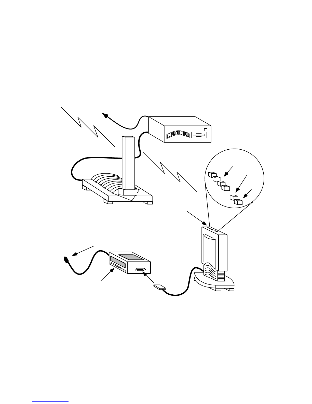
2.1 SYSTEM COMPONENTS
The FreeLINK Wireless LAN System consists of a single Wireless
Ethernet Hub with transmitting antenna and up to 62 Wireless
Transceivers. The FreeLINK System Components are shown in
Figure 2-1, the Wireless Hub at top and the Wireless Transceiver/
Interface Unit at bottom.
Connection to
Network/Backbone
FreeLINK
Wireless Hub Antenna
AC Power Cord
FreeLINK /62
Wireless Ethernet Hub
Signal
Quality
Transmit
Link
LED
Indicators
FLIU-8 Multi-User
Interface Unit
10BASE-T
Ports
Figure 2-1. FreeLINK System Components
Antenna
Cable
Antenna
Page 2 - 1
Page 18

SITE PLANNING AND INSTALLATION
2.2 TRANSCEIVER INSTALLATION
Place the transceiver antenna on a desktop, table, or bookshelf, etc.
and route the cable underneath the feet on the antenna. Using the
captive screws on the cable connector, connect the antenna cable to
the 25-pin D antenna connector on the multi-port or single port
interface unit as shown in Figure 2-2 and Figure 2-3.
Avoid conÞgurations that would require the FreeLINK signals to
pass through metal or concrete walls. Do not position the antenna
next to a metal object such as a Þle cabinet, if the object is in line
with the antenna.
2.3 CONNECTING TRANSCEIVER/INTERFACE UNITS
Connect a data cable to either the RJ-45 port or the AUI port on the
interface unit. Both ports of the single user interface unit are
initially enabled; however, if an AUI cable from a powered device
is connected to the AUI port, the RJ-45 port will be disabled. The
AUI port allows you to use an external Ethernet transceiver to
connect to other Ethernet media such as Þber optics or 10BASE-2
coaxial cable. The AUI port is an industry standard 802.3 AUI
connector. Maximum cable length for the AUI cable is 50 meters.
The RJ-45 interface will support 100 meter cables.
Power Connection
(on rear panel)
RJ-45 ports
FLIU-8
Antenna
RJ-45
Twisted Pair
Cable
Antenna
Cable
Figure 2-2. Connecting FLIU-8 Transceiver/Interface Unit
Page 2 - 2
Page 19

SITE PLANNING AND INSTALLATION
The single port interface unit uses a single RJ-45 connector (see
Figure 2-3, below); the multi-user interface unit will accept eight
RJ-45 Ethernet cables but has no AUI port. Use standard, straightthrough RJ-45 cables to connect the interface units to workstation
Ethernet adapters.
Power Connection
(on rear panel)
RJ-45 port
RJ-45
Twisted Pair
Cable
AUI
FLIU-1
AUI Cable
Antenna
Antenna
Cable
Figure 2-3. Connecting FLIU-1 Transceiver/Interface Unit
After connecting the data interface cables, attach the power cord to
the interface module, and plug it into a 110 Volt outlet.
2.4 TRANSCEIVER SERIAL NUMBERS
As you set up each transceiver, you should record the last six digits
of the serial number imprinted on the bottom of the transceiver
(see Figure 2-4).
You will need the transceiver serial numbers to conÞgure the
Wireless LAN software for the wireless hub. A convenient serial
number record sheet is included in Appendix B.
Page 2 - 3
Page 20

SITE PLANNING AND INSTALLATION
Use these six digits
FLIU-1
Figure 2-4. Wireless Antenna Serial Number Location
2.5 FREELINK WIRELESS ETHERNET HUB
The FreeLINK Wireless Ethernet Hub with transmitting antenna is
shown in Figure 2-5 below.
AC Power In
Fan
110v/220v AC
Power Select
Port Select
Switch
AC Power Out
Manufacturing
Test Only
AUI
10BASE-T
RS232 Serial Port
(Modem)
AUI
Connector
RJ-45
10BASE-T
Antenna
Connectors
Figure 2-5. FreeLINK Wireless Ethernet Hub and Antenna
Page 2 - 4
Wireless Hub Antenna
Page 21

SITE PLANNING AND INSTALLATION
2.5.1 WIRELESS HUB ANTENNA
The FreeLINK Ethernet Hub supports up to 62 wireless
transceivers from an antenna within a service area with a radius of
80 meters. In actuality, the service area size depends upon physical
limitations such as walls, cabinets, stanchions, etc. However, the
spread spectrum radio transmission technology has good
dispersion characteristics, and will ßood irregular areas with the
transmission signal effectively.
The antenna can transmit and receive in 360 degrees of rotation,
focusing on an area from 30 degrees above to 30 degrees below the
horizon. The horizon, in this case is the vertical center of the
transmitting antenna (see Figure 2-6, Wireless Hub Antenna
Service Area). The Wireless Hub Antenna should be positioned
from a minimum of four feet above the ßoor to a maximum of one
foot below the room ceiling. All workstation transceivers must be
within the 80 meter working radius of the Wireless Hub Antenna.
NOTE:
80 Meter Radius
Transmitter Horizon
Figure 2-6. Wireless Hub Antenna Service Area
Building construction can affect these parameters.
+30 Deg.
-30 Deg
Page 2 - 5
Page 22

SITE PLANNING AND INSTALLATION
2.6 WIRELESS HUB CHASSIS
The wireless hub chassis is a turnkey assembly that requires only
to be plugged into a convenient AC power outlet, connected to an
Ethernet backbone or transceiver, and cabled to the wireless hub
transmitting antenna. The front and rear views of the wireless hub
are shown below in Figure 2-7.
AC Power In
Fan
110v/220v AC
Power Select
Port Select
Switch
AC Power Out
Manufacturing
Test Only
Air Vents
AUI
10BASE-T
AUI
Connector
RJ-45
10BASE-T
Antenna
Connector
RS232 Serial Port
(Modem)
Power
On/Off
Floppy
Disk Drive
Figure 2-7. Wireless Hub Front and Rear Views
The wireless hub chassis consists of a metal box which encloses the
electronics and power supply, a 3
1
Ú2 inch ßoppy disk drive, the
transmitting antenna interface board, and the Ethernet interface
board. Figure 2-7 shows the front and rear views of the FreeLINK
Wireless Hub.
On the rear panel of the hub chassis are: a 25-pin D-sub connector
for attaching the antenna cable, as well as two Ethernet ports.
There is an RJ-45 port for 10BASE-T Ethernet connection, and an
AUI port for connecting an AUI cable to an external Ethernet
transceiver for Þber-optic or coaxial cable. An RS232 port provides
access for connection to a modem.
Page 2 - 6
Page 23

SITE PLANNING AND INSTALLATION
2.7 HUB ETHERNET CONNECTIONS
The wireless hubÕs Ethernet interface module incorporates a slide
switch that lets you select either port. To select the 10BASE-T port,
slide the switch all the way to the bottom. To select the AUI port,
slide the switch all the way to the top. See Figure 2-8, below.
AUI
10BASE-T
Figure 2-8. Port Select Slide Switch
To connect the wireless hub to an existing 10BASE-T Ethernet
adapter, use standard, straight-through RJ-45 twisted pair cables.
You can connect the wireless hub to an external Ethernet
transceiver with a standard AUI cable.
2.8 HUB SETUP
Connect the antenna cable to the 25-pin D connector on the
wireless hub rear panel (see Figure 2-7) with the attached captive
screws. Position the wireless hub so that it is accessible to the
wired Ethernet backbone LAN or network segment.
The wireless hub antenna should be positioned above the wireless
hub chassis, on a Þle cabinet, a desktop, or a wall (see Figure 2-9 on
page -9). You can even hang the antenna from the ceiling if you
desire.
Make sure that you do not obstruct the cooling air vents in the
NOTE:
top and bottom of the antennas.
Page 2 - 7
Page 24

SITE PLANNING AND INSTALLATION
2.9 ORIENTING THE HUB ANTENNA
The ideal location for the transmitting antenna is from four feet
above the ßoor to one foot below the ceiling. The antenna should
be located so that all transceivers are within the maximum
80 meter radius service area.
To service more than one ßoor will require either a second wireless
hub, or extending the Ethernet cables through the ßoor to the
individual workstations.
2.10 CONFIGURING THE WIRELESS HUB SOFTWARE
See Chapter 3 for conÞguration information. After conÞguration,
align the components as described in Section 2.11.
2.11 ALIGNING FreeLINK COMPONENTS
You can orient the FreeLINK components prior to loading network
software, as the wireless hub transmitter and transceivers establish
a wireless communications protocol that is independent of data
from the Ethernet network.
To orient the transceiver antenna, follow this procedure:
¥ Locate the transmitting antenna and transceivers as described
in the preceding sections of this chapter. Then, with both the
transmitter and transceiver(s) powered on, check the LEDs on
top of each transceiver unit. See Figure 2-9 on page -9.
¥ The green Link Status LED may be ßashing, indicating that a
link with the transmitter is not yet established. One or more of
the yellow Signal Level LEDs may be ßashing at this time also.
¥ Rotate the antenna 360 degrees slowly as you observe the
yellow Signal Level LEDs. Note the direction in which the
maximum number of Signal Level LEDs are illuminated. All
Signal Level LEDs need not be lit to establish a link.
Page 2 - 8
Page 25

SITE PLANNING AND INSTALLATION
¥ When the maximum number of Signal Level LEDs is noted,
stop rotating the antenna and wait 30 seconds. Then observe
the green Link LED. It should stop ßashing and illuminate
solidly, indicating a link with the transmitter.
LED
Indicators
Figure 2-9. Transceiver LEDs
Signal
Quality
Transmit
Link
FreeLINK
Wireless Transceiver
Antenna
If you fail to establish a link, see Appendix A,
helpful information.
Troubleshooting
Page 2 - 9
, for
Page 26

SITE PLANNING AND INSTALLATION
Page 2 - 10
Page 27

INSTALLING SYSTEM SOFTWARE
CHAPTER 3
INSTALLING SYSTEM SOFTWARE
The FreeLINK Wireless LAN software conÞgures the FreeLINK
network and maintains an internal list of wireless transceiver serial
numbers to prevent unauthorized network access. The wireless
hub will automatically refuse access privileges to any wireless
transceiver with an unrecognizable serial number.
The FreeLINK Wireless LAN software is compatible with any
SNMP-compliant network management application, such as
Cabletron SystemsÕ Remote LANVIEW/Windows, or SPECTRUM.
3.1 CONFIGURING THE SOFTWARE
The FreeLINK Wireless LAN software is supplied on a 31Ú2 inch
DOS format ßoppy diskette. We suggest that you make a copy of
the diskette to use for software installation, and put the original in
a safe place.
To conÞgure the Wireless LAN software you will need an IBM
NOTE:
PC or compatible, and DOS version 3.X or later.
Installation of system software is a two-step process. The software
is Þrst conÞgured using a PC, and then, after conÞguration, it is
installed into the wireless hub. To conÞgure the FreeLINK Wireless
LAN software follow the steps outlined below:
¥ With the PC powered on and booted up, insert the software
diskette copy into a ßoppy drive. Select the drive, and type:
SETUP <Enter>
appear. Press
at the prompt. The Copyright screen will
<Enter>
to move to the next screen.
Page 3 - 1
Page 28

INSTALLING SYSTEM SOFTWARE
You can press F1 to display more information about any screen,
NOTE:
or press F2 to access general help. Use the Page Up and Page
Down keys to move between pages. Press F10 to exit the
conÞguration program.
¥ The
DeÞne Hub Parameters
screen will appear. This screen
contains three Þelds that are used for setting the LANÕs
Internet Protocol parameters.
The following Þelds are used for SNMP management. If you
NOTE:
are not using SNMP management, these Þelds can be set to
the default values.
IP Address
The wireless hubÕs Internet Protocol Address x.x.x.x where x is a
one to three digit decimal number in the range 0 to 255. If you
donÕt use TCP/IP and you donÕt have an assigned IP address, you
may use the address 192.0.2.n, which is a test address (n is any
number from 1 to 255, inclusive).
Default Gateway
An address in the form x.x.x.x as above, deÞning a gateway, or
bridge to another network. If your FreeLINK LAN will not access
another network, enter 0.0.0.0 as the Default Gateway address.
Network Mask
A number in x.x.x.x notation deÞning a subnetwork. If you are not
using a subnetted network, leave the default set to 0.0.0.0.
When you have Þnished setting these parameters, press
move to the
¥ You use the
Select Modem Speed
Select Modem Speed
hubÕs serial port parameters. The serial port is used for out-ofband network management. The modem may actually be a
Null Modem (crossed over cable), from the RS232 serial port on
the network management computer.
Page 3 - 2
screen.
screen to set the wireless
<Enter>
to
Page 29

INSTALLING SYSTEM SOFTWARE
The available baud rates are: 100, 300, 1200, 2400, 4800, 9600,
and 19,200. Use the Up Arrow and Down Arrow keys to
highlight a baud rate. After you have selected the baud rate,
press <Enter> to proceed to the Transceiver Names/Ethernet
Addresses screen.
¥ The Transceiver Names/Ethernet Addresses screen lets you
create, view, and maintain the wireless hubÕs internal list of
wireless transceivers. Before the hub will accept data from a
transceiver, the hub checks this list to determine if the
transceiver has access privileges.
To add a transceiver use the Add command. To display a listing of
the existing transceivers, use the List command. Use the Left
Arrow and Right Arrow keys to move between the screenÕs seven
commands. These commands are deÞned below:
List
This command displays a list of the names and serial numbers of
the wireless transceivers conÞgured on your network.
Add
This command lets you add a wireless transceiver to your
network. Add displays three Þelds: Next Available Transceiver
Number, Name Field, and Serial Number Field.
When entering transceiver serial numbers, use the last six
NOTE:
digits of the serial number on the bottom of the Wireless
Transceiver Antenna. After entering the serial numbers,
always save the new list using the Save command.
Delete
This command lets you delete a wireless transceiver from your
network. Choosing Delete displays a box with a Þeld for a wireless
transceiver number. To delete a wireless transceiver, enter its
Transceiver Number (i.e., 1, 2, 3, etc.) and press <Enter>. The
software will then display a box with the transceiverÕs serial
number, and ask for conÞrmation before the transceiver is deleted.
Press <Enter> after conÞrmation to delete your selection.
Page 3 - 3
Page 30

INSTALLING SYSTEM SOFTWARE
Change
This command lets you change information Þelds of any wireless
transceiver. Choosing Change displays Þelds for Wireless
Transceiver number (i.e., 1, 2, 3, etc.), name, and serial number. To
change the information, enter the Wireless Transceiver number,
and press <Enter>.
Use the Up Arrow and Down Arrow keys to select a Þeld to
change... then [make the change], [select the next Þeld] and press
<Enter> to accept the changes.
Save
This command saves the changes to the Wireless Transceiver List
to the Þle XCVRS.CNF in the same directory as the conÞguration
utility.
Reload
This command reloads the Wireless Transceiver List from the
XCVRS.CNF Þle, enabling you to modify the Þle since the last time
you saved it.
End
This command exits the current screen. Press <F10> to exit the
conÞguration program.
If you are not installing SNMP management, you can exit the
program at this time by pressing <F10>. You can install the
conÞgured software in the wireless hub at this time. Insert the
conÞgured diskette into the wireless hub disk drive and restart the
wireless hub. The hub will boot and be ready to use in
approximately two minutes.
If you are installing SNMP management, you must deÞne the
NOTE:
Wireless HubÕs Community List. Press Page Down to
access the DeÞne Wireless HubÕs Community List screen.
Then, use the procedure on the following pages.
Page 3 - 4
Page 31

INSTALLING SYSTEM SOFTWARE
The DeÞne the Wireless HubÕs Community List screen lets you
conÞgure and maintain the wireless hubÕs Community List. The
Community List contains passwords and access levels for all users
within the community. Each user password has a Read and/or
Write permission associated with it. The access levels are: Public,
which has Write permission, and World, which has Read Only
permission.
The wireless hub will accept Get commands from Read
community members. The hub will accept both Get and Set
commands from Read/Write community members.
¥ The DeÞne the Wireless HubÕs Community List screen uses
seven commands. You use the Right Arrow and Left Arrow
keys to highlight the command you want to execute. Press
<Enter> to execute the command. The commands are deÞned
as follows:
List
This command displays the name, index, and access level of each
user in the wireless hubÕs community list.
Add
This command lets you add a community name. The information
Þelds for this command are: Next Available Index, Community
Name, and Access Field.
Change
This command lets you change an entry in the Community Name
List. Choosing Change displays entries in the Community Name
List. Use the Up Arrow and Down Arrow keys to select an entry to
be changed. To make a change, enter the new the information and
press <Enter>.
Save
This command saves the changes to the Community Name List.
Page 3 - 5
Page 32

INSTALLING SYSTEM SOFTWARE
Reload
This command reloads the Community Name List from the file,
enabling you to modify the Community Name List since the last
time you saved it.
End
This command exits the current screen. You can use the F10 key to
exit the conÞguration program.
¥ The Select Channel screen lets you select one of Þve spread
spectrum channels on which to operate the wireless hub.
The hub can operate on any of Þve available channels.
Channel
Select a channel from 1 to 5. The default channel is 1. If multiple
hubs are in place, use a different channel for each hub. When you
have selected a channel for the wireless hub, press <Enter> to
register your selection. You can press <F10> to exit the
conÞguration program now if your conÞguration is correct.
At this time you can place the conÞgured diskette into the wireless
hubÕs disk drive, and restart the wireless hub. The hub will boot
and be ready for operation in approximately two minutes.
Refer to section 2.10 for information on orientating the hub and
NOTE:
transceiver antennas.
Page 3 - 6
Page 33

TROUBLESHOOTING
APPENDIX A
TROUBLESHOOTING
The following is a checklist of helpful hints to aid in
troubleshooting Wireless Hub and transceiver problems:
Problem: The wireless transceiverÕs green communications
link LED will not blink.
Solution: Check all cable connections to make sure that they
are secure. Check the wall outlet to make sure that it is
delivering power to the Wireless transceiver.
Problem: The wireless transceiverÕs green communications
link LED has been fast blinking for more than a minute, and its
amber signal strength LEDs are also blinking.
Solution: Move the wireless transceiver closer to the wireless
hub.
Problem: The wireless transceiverÕs green communications
link LED continues to blink slowly.
Solution: Check to make sure that you have correctly entered the
wireless transceiverÕs serial number in the wireless hubÕs
access list.
Page A - 1
Page 34

TROUBLESHOOTING
Page A - 2
Page 35

TRANSCEIVER SERIAL NUMBERS
APPENDIX B
TRANSCEIVER SERIAL NUMBERS
Record the serial number and location of each transceiver in the
following table.
Tcvr No. Serial No. Owner Location
Page B - 1
Page 36

TRANSCEIVER SERIAL NUMBERS
Tcvr No. Serial No. Owner Location
Page B - 2
Page 37

INDEX
INDEX
A
Add command 3-3, 3-5
aligning FreeLINK
components
Antenna serial No.Õs 2-3, 2-4
AUI port
2-2
2-8
B
baud rates 3-2
C
Cabletron Technical Support
1-2
Change command
channel
conÞguring the software
conÞguring the Wireless Hub
connecting FLIU-1 transceiver/
connecting FLIU-8 transceiver/
connecting transceiver/
3-6
Software
interface unit
interface unit
interface units
3-4, 3-5
3-1
2-8
2-3
2-2
2-2
E
End command 3-4, 3-6
F
FreeLINK architecture 1-5
G
getting help 1-2
H
Hub SETUP 2-7
I
installing system software 3-1
IP Address
3-2
L
Link Status LED 2-8
List command
3-3, 3-5
D
data security 1-4
DeÞne Hub Parameters screen
3-2
DeÞne the Wireless HubÕs
Community List screen
3-4
Delete command
N
Network Mask 3-2
O
orienting the hub antenna 2-8
3-3
Index - 1
Page 38

INDEX
P
Port Select Slide Switch 2-7
R
Reload command 3-4, 3-6
RJ-45 cables
RJ-45 port disabled
RS232 port
2-3
2-2
2-6
S
safety information 1-5
Save command
Select Channel screen
Select Modem Speed screen
service area size
SETUP
Signal Quality LEDs
SNMP network management
spread spectrum technology
system components
system LED indicators
3-1
3-1
1-4
3-4, 3-5
3-6
3-2
2-5
2-8
2-1
1-8
W
Wireless Hub 1-6
front and rear views
Wireless Hub Antenna
Wireless Hub Chassis
Wireless LAN System
components
Wireless LAN System Features
1-3
Wireless Transceiver/Interface
Units
1-6
2-6
2-5
2-6
1-3
T
transceiver LEDs 2-9
Transceiver Names/Ethernet
Addresses screen
troubleshooting
Index - 2
A-1
3-3
Page 39

Page 40

35 Industrial Way, P.O. Box 5005
Rochester, New Hampshire 03867-0505
P/N 9030833 May 1993
 Loading...