

Page 1

FDMMIM, FDMMIM-04,
FDMMIM-24, and FDMMIM-30
FDDI CONCENTRATOR
ETHERNET to FDDI
BRIDGE MODULES
INSTALLATION and
USER’S GUIDE
Cabletron Systems, P. O. Box 5005, Rochester, NH 03867-0505
The Complete Networking Solution
Page 2

NOTICE
NOTICE
Cabletron Systems reserves the right to make changes in
specifications, hardware, firmware, software, and other information
contained in this document without prior notice. The reader should
in all cases consult Cabletron Systems to determine whether any
such changes have been made.
IN NO EVENT SHALL CABLETRON SYSTEMS BE LIABLE FOR ANY
INCIDENTAL, INDIRECT, SPECIAL, OR CONSEQUENTIAL
DAMAGES WHATSOEVER (INCLUDING BUT NOT LIMITED TO
LOST PROFITS) ARISING OUT OF OR RELATED TO THIS MANUAL
OR THE INFORMATION CONTAINED IN IT, EVEN IF CABLETRON
SYSTEMS HAS BEEN ADVISED OF, KNOWN, OR SHOULD HAVE
KNOWN, THE POSSIBILITY OF SUCH DAMAGES.
Copyright July 1994
Cabletron Systems, Inc
P.O. Box 5005
Rochester, NH 03867-0505
All Rights Reserved
Printed in the United States of America
Part number: 9030670-03 July 1994
Multi Media Access Center, SPECTRUM, Remote LANVIEW,
and LANVIEW are registered trademarks and FDMMIM,
FDMMIM-04, FDMMIM-24, FDMMIM-30, FDCMIM-04,
FDCMIM-08, FDCMIM-24, FDCMIM-28, IRM, IRM-2, IRM-3,
IRBM, EMME, TRMM, CXRMIM, TPRMIM, FORMIM, Flexible
Network Bus, MMAC-3FNB, MMAC-5FNB, MMAC-8FNB, and
MMAC-M8FNB are trademarks of Cabletron Systems, Inc.
CompuServe is a registered trademark of CompuServe.
Ethernet is a trademark of Xerox, Inc.
IBM is a registered trademark of International Business Machines Corp.
UNIX is a registered trademark of Unix System Laboratories, Inc.
VT-220 and VT-320 are trademarks of Digital Equipment Corp.
Windows is a registered trademark of Microsoft Corp.
i
Page 3

FCC NOTICE
FCC NOTICE
This device complies with Part 15 of the FCC rules. Operation is
subject to the following two conditions: (1) this device may not cause
harmful interference, and (2) this device must accept any interference
received, including interference that may cause undesired operation.
NOTE: This equipment has been tested and found to comply with the
limits for a Class A digital device, pursuant to Part 15 of the FCC
rules. These limits are designed to provide reasonable protection
against harmful interference when the equipment is operated in a
commercial environment. This equipment uses, generates, and can
radiate radio frequency energy and if not installed in accordance with
the operator’s manual, may cause harmful interference to radio
communications. Operation of this equipment in a residential area is
likely to cause interference in which case the user will be required to
correct the interference at his own expense.
WARNING: Changes or modifications made to this device which are
not expressly approved by the party responsible for compliance could
void the user’s authority to operate the equipment.
DOC NOTICE
This digital apparatus does not exceed the Class A limits for radio
noise emissions from digital apparatus set out in the Radio
Interference Regulations of the Canadian Department of
Communications.
Le présent appareil numérique n’émet pas de bruits radioélectriques
dépassant les limites applicables aux appareils numériques de la
class A prescrites dans le Règlement sur le brouillage radioélectrique
édicté par le ministère des Communications du Canada.
Printed on recycled paper
ii
Page 4

NOTICE
SAFETY INFORMATION
CLASS 1 LASER TRANSCEIVERS
CLASS 1
LASER PRODUCT
Class 1 Laser Products
The FDMMIM-30 connectors use Class 1 Laser transceivers. Read
the following safety information before installing or operating the
FDMMIM-30.
The Class 1 laser transceivers use an optical feedback loop to
maintain Class 1 operation limits. This control loop eliminates the
need for maintenance checks or adjustments. The output is factory
set, and does not allow any user adjustment. Class 1 Laser
transceivers comply with the following safety standards:
• 21 CFR 1040.10 and 1040.11 U.S. Department of Health and
Human Services (FDA).
• IEC Publication 825 (International Electrotechnical
Commission).
• CENELEC EN 60825 (European Committee for
Electrotechnical Standardization).
When operating within their performance limitations, laser
transceiver output meets the Class 1 accessible emission limit of all
three standards. Class 1 levels of laser radiation are not considered
hazardous.
iii
Page 5

FCC NOTICE
SAFETY INFORMATION
CLASS 1 LASER TRANSCEIVERS
Laser Radiation and Connectors
When the connector is in place, all laser radiation remains within
the fiber. The maximum amount of radiant power exiting the fiber
(under normal conditions) is -12.6dBm or 55x10 -6 watts.
Removing the optical connector from the transceiver allows laser
radiation to emit directly from the optical port. The maximum
radiance from the optical port (under worst case conditions) is 0.8 W
cm-2 or 8x10 3 W m-2 sr-1.
Do not use optical instruments to view the laser output. The use of
optical instruments to view laser output increases eye hazard. When
viewing the output optical port, you must remove power from the
network adapter.
iv
Page 6

CONTENTS
CONTENTS
CHAPTER 1 INTRODUCTION
1.1 Using this Manual ........................................................................1-2
1.2 Getting Help ..................................................................................1-4
1.3 The FDMMIM FDDI Concentrator and Ethernet to FDDI
Bridging Modules ..........................................................................1-4
1.4 FDMMIM Features .......................................................................1-7
CHAPTER 2 INSTALLING THE FDMMIM
2.1 Before you Install the FDMMIM . . .............................................2-1
2.1.1 Adding MIMs to an MMAC.................................................2-2
2.1.2 MMAC Configurations ........................................................2-4
2.1.3 IRM-3 and Ethernet MIMs with FDMMIMs .....................2-4
2.1.4 EMME and RMIMs with an FDMMIM..............................2-5
2.2 Installing the FDMMIM ...............................................................2-6
2.2.1 Setting Jumpers ..................................................................2-6
2.2.2 Setting Configuration Switches ..........................................2-7
2.2.3 Installing into the MMAC ...................................................2-9
2.3 Connecting Fiber Optic Cabling .................................................2-10
2.4 FDMMIM-04 and FDMMIM-24 Master Port
Cable Connections.......................................................................2-13
2.5 Twisted Pair Pinout Configuration ............................................2-13
2.6 Master Ports and LANVIEW......................................................2-14
2.7 FDMMIM and LANVIEW ..........................................................2-15
2.7.1 Ethernet LEDs...................................................................2-15
2.7.2 FDDI LEDs ........................................................................2-17
CHAPTER 3 CONNECTING TO LOCAL MANAGEMENT
3.1 Connecting a Console....................................................................3-1
3.2 Powering-up the FDMMIM: Diagnostic Tests.............................3-4
3.3 Manually Resetting the FDMMIM...............................................3-6
CHAPTER 4 GETTING STARTED WITH FDMMIM
LOCAL MANAGEMENT
4.1 Understanding the Screens and Commands ...............................4-1
4.2 Using the Management Keyboard................................................4-2
4.3 Navigating through Local Management......................................4-2
v
Page 7

CONTENTS
4.4 Screen Organization......................................................................4-4
4.4.1 Screen Header and Message Bar Section...........................4-4
4.4.2 Data Sections and Command Menus .................................4-7
4.5 Setting FDMMIM Operating Parameters ...................................4-7
CHAPTER 5 USING THE INFORMATION SCREENS
5.1 The System Information Screen...................................................5-1
5.1.1 NETWORK TRAFFIC Data................................................5-2
5.1.2 FDDI Data ...........................................................................5-3
5.1.3 FILTER DATABASE Data..................................................5-5
5.1.4 BRIDGE PROTOCOL Data ................................................5-6
5.1.5 System Information Screen Commands.............................5-8
5.2 The Network Traffic Screen .........................................................5-9
5.2.1 Network Traffic Screen Data ............................................5-10
5.2.2 Network Traffic Screen Commands .................................5-12
5.3 The Ring Map Screen..................................................................5-13
5.3.1 Ring Map Screen Data ......................................................5-14
5.3.2 Ring Map Screen Commands ...........................................5-15
5.3.3 Adjusting the Scroll Number (n) ......................................5-15
5.4 The Node Information Screen ....................................................5-16
5.5 The Message Log Screen.............................................................5-18
5.5.1 Message Log Data .............................................................5-20
5.5.2 Message Log Screen Commands.......................................5-20
CHAPTER 6 SETTING UP THE FDMMIM
6.1 The Setup Screen ..........................................................................6-1
6.1.1 Setup Screen Data...............................................................6-2
6.1.2 Setup Screen Commands ....................................................6-6
6.2 The Community Names Table Screen .........................................6-7
6.2.1 Community Names Table Screen Data ..............................6-8
6.2.2 Community Names Table Screen Commands ...................6-9
6.3 TFTP Code Download Setup Screen ............................................6-9
6.3.1 TFTP Code Download Setup Screen Data .......................6-10
6.3.2 TFTP Code Download Setup Screen Commands.............6-10
6.4 Image File Download with UNIX ...............................................6-11
6.5 Forcing an Image File Download ...............................................6-13
6.5.1 Forcing a Download with FDMMIM/LM..........................6-13
6.5.2 Forcing a Download with BOOTP ....................................6-14
vi
Page 8

CONTENTS
CHAPTER 7 SPANNING TREE
7.1 The Bridge Protocol Screen ..........................................................7-1
7.1.1 Bridge Protocol Screen Data ...............................................7-2
7.1.2 Bridge Protocol Screen Commands ....................................7-5
7.2 The Bridge Port Parameters Screen ............................................7-5
7.2.1 Bridge Port Parameters Screen Data .................................7-6
7.2.2 Bridge Port Parameter Screen Commands ........................7-7
CHAPTER 8 THE FILTERING DATABASES
8.1 Bridge Operation...........................................................................8-1
8.2 The Filter Database Screen..........................................................8-2
8.2.1 Filter Database Screen Data ..............................................8-3
8.2.2 Filter Database Screen Commands ....................................8-4
8.3 Display Filter Entries Screen.......................................................8-5
8.3.1 Display Filter Entries Screen Data ....................................8-6
8.3.2 Display Filter Entries Screen Commands .........................8-7
8.4 Create Filter Entry Screen ...........................................................8-7
8.4.1 Create Filter Entry Screen Data ........................................8-8
8.4.2 Create Filter Entry Screen Commands..............................8-9
8.5 Delete Filter Entry Screen............................................................8-9
8.5.1 Delete Filter Entry Screen Data.......................................8-10
8.5.2 Delete Filter Entry Screen Commands ............................8-10
8.6 Special Database Screen.............................................................8-11
8.6.1 Special Database Screen Data ..........................................8-12
8.6.2 Special Database Screen Commands ...............................8-13
CHAPTER 9 CONTROLLING CONCENTRATOR
MODULES AND PORTS
9.1 The FDDI Configuration Screen ..................................................9-1
9.1.1 FDDI Configuration Screen Data .......................................9-2
9.1.2 FDDI Configuration Screen Commands ............................9-4
9.2 Concentrator Status and Bridge Operations...............................9-4
vii
Page 9

CONTENTS
APPENDIX A FDMMIM/LM MESSAGES
Information Messages.........................................................................A-1
Warning Messages ..............................................................................A-1
Error Messages ...................................................................................A-9
APPENDIX B SPECIFICATIONS
APPENDIX C BASIC FDDI NETWORKS
Basic FDDI Concepts ..........................................................................C-1
FDDI Media Access Protocol........................................................C-1
Reliability .....................................................................................C-3
ANSI Standard X3T9.5 ................................................................C-4
FDDI Connection Rules................................................................C-8
FDDI Devices ......................................................................................C-9
Design Considerations for FDDI Networks.....................................C-14
Ring Length ................................................................................C-14
Drive Distance ............................................................................C-14
Attenuation .................................................................................C-15
Bandwidth...................................................................................C-15
Number of Stations ...........................................................................C-15
INDEX
viii
Page 10

INTRODUCTION
CHAPTER 1
INTRODUCTION
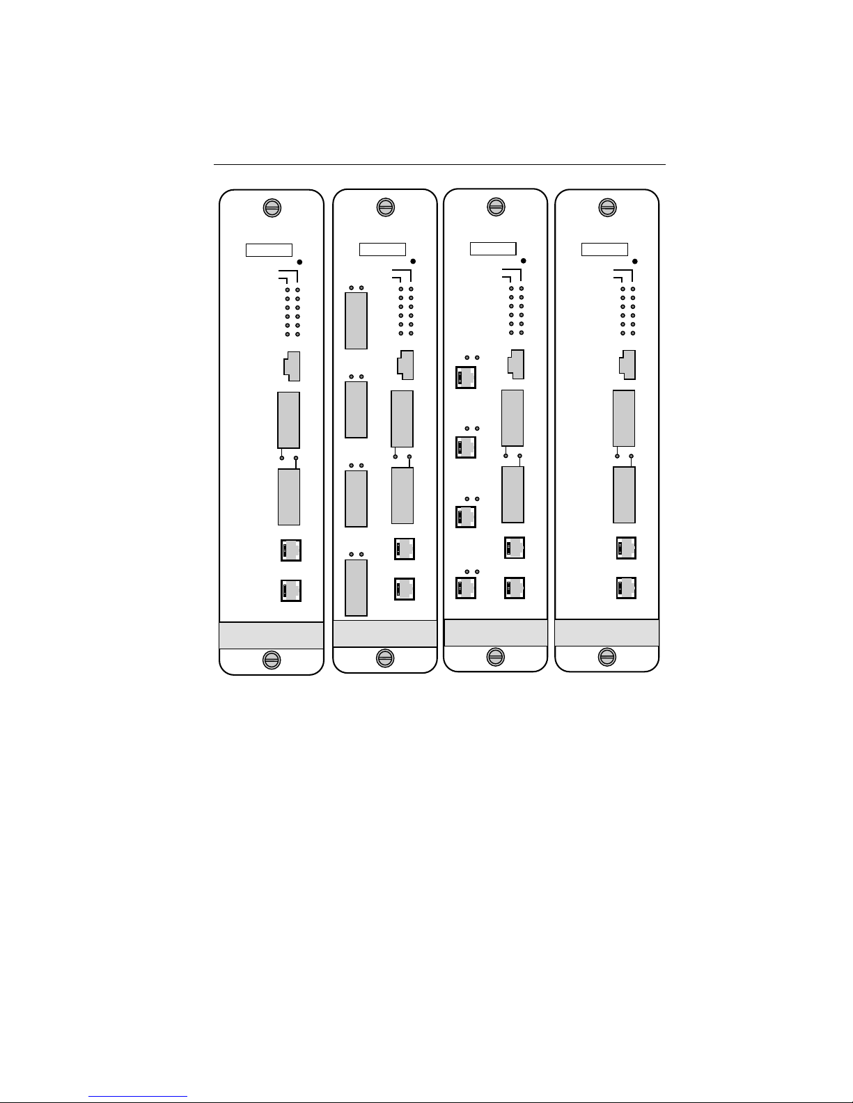
The FDMMIM, FDMMIM-04, FDMMIM-24, and FDMMIM-30
combine the functions of an FDDI concentrator with those of an
Ethernet/802.3 to FDDI bridge. When distinguishing one module
from the other, keep the following in mind:
• All modules contain FDDI A and B ports which bridge to a
Multi Media Access Center hub Ethernet bus.
• The FDMMIM-04 and FDMMIM-24 also contain four M type
concentrator ports.
• The master ports of the FDMMIM-24 are unshielded twisted
pair connections.
• The FDMMIM, FDMMIM-04, and the FDMMIM-24 A and B
ports are multimode fiber optic devices.
• The FDMMIM-30 is a single mode fiber optic module that
uses a class 1 laser. This laser increases the link length from
the multimode maximum drive distance of 2 kilometers (km)
to a single mode maximum of 40 km.
This manual describes how to install the FDMMIM, FDMMIM-04,
FDMMIM-24, and FDMMIM-30 and explains how to use the onboard management tool, FDMMIM Local Management, to configure,
monitor, and control the bridge/concentrator.
Unless otherwise noted, the term FDMMIM refers to the FDMMIM,
FDMMIM-04, FDMMIM-24, and FDMMIM-30. In addition, the
terms FDMMIM/LM, Local Management, and LM refer to FDMMIM
Local Management.
1-1
Page 11

INTRODUCTION
1.1 USING THIS MANUAL
You should have a general working knowledge of FDDI networks and
the ANSI X3T9.5 standard prior to installing the FDMMIM. (If you
need a review of FDDI, see Appendix C.) The following summarizes
the organization of this manual.
Chapter 1, Introduction, describes the FDMMIM and its features.
Chapter 2, Installing the FDMMIM, explains how to configure and
install the FDMMIM in a Multi Media Access Center chassis. This
chapter also explains each LANVIEW indicator.
Chapter 3, Connecting to Local Management, explains how to
connect to, and begin using, FDMMIM Local Management. This
chapter also explains the power-up diagnostic tests.
Chapter 4, Getting Started with FDMMIM Local Management,
explains conventions used in this manual to describe the Local
Management screens, and summarizes the organization of Local
Management.
Chapter 5, Using the Information Screens, describes the
following Local Management screens:
System Information Displays system status information
and contains the menu choices that
provide access to all Local
Management screens.
Network Traffic Displays detailed information about
network traffic loads at both the
Ethernet and FDDI ports.
Ring Map Displays the logical topography of the
FDDI ring.
Node Information Displays detailed information specific
to a selected node on the Ring Map.
Message Log Displays the history file that keeps
track of information, warning, and
error messages generated by Local
Management.
1-2
Page 12

INTRODUCTION
Chapter 6, Setting Up the FDMMIM, explains the following Local
Management screens:
Setup Controls FDMMIM parameters.
Community Set permissions for remote access to
Names Table the FDMMIM, and create Local
Management passwords.
TFTP Code Set conditions for updating the
Download Setup FDMMIM firmware.
This chapter also provides basic TFTP code downloading
instructions, and guidelines for setting up a UNIX workstation to
handle an image file download.
Chapter 7, Spanning Tree, explains the Bridge Protocol screen and
the Port Parameters screen, which let you control the participation of
the FDMMIM in the Spanning Tree Algorithm.
Chapter 8, The Filtering Databases, explains the purpose of the
Acquired, Permanent, and Special Databases, and how to view/
manipulate their contents.
Chapter 9, Controlling Concentrator Modules and Ports,
explains how to enable/disable FDDI concentrator modules and ports
through the FDDI Configuration screen.
Appendix A, FDMMIM/LM Messages, lists each message that you
can encounter in Local Management, the probable cause of the
message, and some possible solutions.
Appendix B, Specifications, lists the electrical, physical, and
environmental specifications of the FDMMIM bridge/concentrator.
Appendix C, Basic FDDI Networks, covers basic concepts of FDDI
networks, FDDI devices, and design/installation considerations.
1-3
Page 13

INTRODUCTION
1.2 GETTING HELP
If you have any questions, comments or suggestions related to the
FDMMIM or this manual, you can contact Cabletron Systems
Technical Support by any of the following methods:
By phone: Monday through Friday between
8 A.M. and 8 P.M. Eastern Standard
Time at (603) 332-9400.
By CompuServe: GO CTRON from any ! prompt
By Internet mail: support@ctron.com
Before calling, please have the product serial number (located on the
FDMMIM front panel) and product type (FDMMIM, FDMMIM-04,
FDMMIM-24, FDMMIM-30) ready.
1.3 THE FDMMIM FDDI CONCENTRATOR AND ETHERNET
TO FDDI BRIDGING MODULES
The FDMMIM provides an ANSI X3T9.5 and IEEE 802.1d compliant
media interface that connects an Ethernet and FDDI network using
translation bridging. It contains the A and B ports of a modular
Dual Attached Station (DAS) or Dual Attached Concentrator (DAC).
The FDMMIM works in conjunction with the FDCMIM family of
Cabletron Systems FDDI Concentrator Modules. These devices
provide 4 or 8 M-type port connections for various cable types.
The FDCMIM-04 and FDCMIM-08 have FDDI multi-mode connector
ports. The FDCMIM-24 and FDCMIM-28 have unshielded twisted
pair connector ports. The FDCMIM-34 and FDCMIM-38 have single
mode fiber connector ports. The FDCMIM-44 and FDCMIM-48 have
shielded twisted pair connector ports. All of these devices reside in a
Multi Media Access Center (MMAC).
You can manage the FDMMIM remotely through an SNMP
management tool such as Cabletron Systems’ SPECTRUM or
Remote LANVIEW/Windows, or locally through an RS-232 console
port with the on-board management tool called FDMMIM Local
Management.
1-4
Page 14
INTRODUCTION
FDMMIM
SN
ENET
FDDI
RESET
PWR
TWR
XMT
RCV
WRP
ROP
FDDI
FDMMIM-04
SN
STBY
SYOK
XMT
RCV
CLN
POK
B
Y
P
A
PST
S
S
F
D
D
I
A
LINK
PST
F
D
D
I
B
M
O
D
PST
E
M
C
O
N
S
O
L
E
RESET
ENET
FDDI
LNKPST
PWR
TWR
XMT
RCV
1
WRP
ROP
LNK
2
LNK
3
LNK
4
FDDI
FDMMIM-24
SN
STBY
SYOK
XMT
RCV
CLN
POK
B
Y
P
A
S
S
F
D
D
I
A
LINK
F
D
D
I
B
M
O
D
E
M
C
O
N
S
O
L
E
RESET
ENET
FDDI
PWR
TWR
XMT
RCV
WRP
ROP
LNKPST
1
LNKPST
2
LNKPST
3
LNKPST
4
UTP-PMD
FDDI
FDMMIM-30
SN
STBY
SYOK
XMT
RCV
CLN
POK
B
Y
P
A
S
S
F
D
D
I
A
LINK
F
D
D
I
B
M
O
D
E
M
C
O
N
S
O
L
E
RESET
ENET
FDDI
PWR
TWR
XMT
RCV
WRP
ROP
SMF-PMD
FDDI
STBY
SYOK
XMT
RCV
CLN
POK
B
Y
P
A
S
S
F
D
D
I
A
LINK
F
D
D
I
B
M
O
D
E
M
C
O
N
S
O
L
E
Figure 1-1. FDMMIM Modules
Local Management for the FDMMIM provides module and network
information such as frame counts, error breakdowns, and bridge
information. You can view LM on a Digital Equipment Corporation
VT220 or VT320 terminal, or a PC with terminal emulation
software. Since the FDMMIM is ANSI X3T9.5 compliant, FDMMIM
Local Management can provide Station Management (SMT)
information such as ring state, station state, and ring configuration.
1-5
Page 15

INTRODUCTION
The FDMMIM can accept an Optical Bypass Switch (Figure 1-2). If
you use this optional device, the fiber optic connections pass through
the switch, automatically switching to a bypass mode. This feature
maintains ring continuity, if the bridge module loses power.
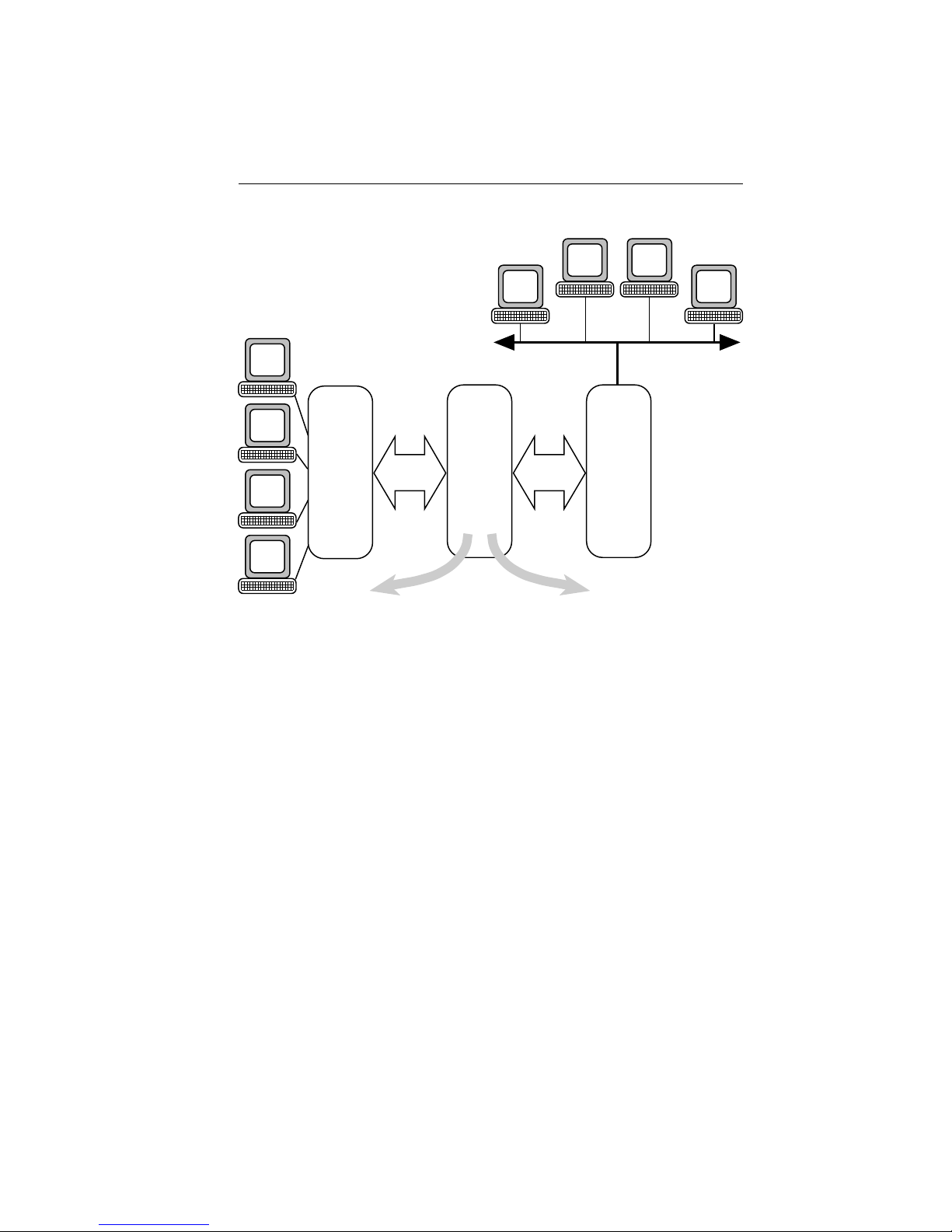
The MMAC Ethernet “A” Bus provides the Ethernet interface.
Ethernet traffic accesses the bus through the EMME (Ethernet
Management Module with Ethernet), IRM (Intelligent Repeater
Module) series, or any Cabletron Ethernet Management Module.
Figure 1-3 represents a typical FDDI to Ethernet bridge.
1-6
Figure 1-2. Optical Bypass Switch
Page 16
INTRODUCTION
ETHERNET
NETWORK
FDCMIM
MMAC
FDDI
BUS
FDMMIM
FDDI Ring
Connections
AB
MMAC
ETHERNET
BUS
IRM3
FIGURE 1-3. Bridging FDDI to Ethernet with the FDMMIM
1.4 FDMMIM FEATURES
LANVIEW
LANVIEW is a visual diagnostic and status monitoring system
developed by Cabletron Systems. LEDs on the FDMMIM front panel
indicate the status of the FDMMIM and can help identify module
and physical layer problems.
Hot Swapping
Like all Cabletron Systems Media Interface Modules, you can
remove the FDMMIM from, and insert it into, an MMAC without
turning off the power to the rest of the modules in the hub.
1-7
Page 17

INTRODUCTION
Management
An RS-232 console port gives you direct access to FDMMIM Local
Management. Here you can check bridge statistics, and control the
bridge and FDDI port configuration. The FDMMIM also supports
SNMP network management tools such as Cabletron Systems’
SPECTRUM products.
Shared Memory
The FDMMIM has 4 Mbytes of DRAM buffer memory which it uses
for storing data frames. The on-board processor and other support
logic also use this memory.
Local Memory
In addition to the buffer memory, the FDMMIM CPU operates with
4 Mbytes of DRAM, and uses 512 Kbytes of FLASH memory to store
its on-board software.
Battery Back-up RAM
The FDMMIM saves its Local Management statistics and operating
parameters in battery backed up RAM. The battery retains userconfigured settings, when the FDMMIM loses power or is turned off.
Source Address Table Size
The FDMMIM uses a learning and filtering algorithm and can retain
up to 8,192 source address static or dynamic table entries.
Spanning Tree Algorithm
The FDMMIM supports both 802.1d and DEC Spanning Tree
Algorithm (STA) protocols.
FlASH EEPROM Memory Support
As Cabletron Systems makes enhancements to Local Management,
you can upgrade your FDMMIM by downloading new software
images into the FDMMIM FLASH EEPROM (electrically erasable
programmable read only memory).
Through Local Management, you can control the download path of
an image file between your FDMMIM and a network server, such as
a remote network management tool like Remote LANVIEW/Windows
or even a UNIX workstation. The FDMMIM also provides a way to
broadcast a request for an image file using the BOOTP switch.
Chapter 6 provides more information regarding image file download
using FDMMIM Local Management or the BOOTP switch.
1-8
Page 18

INSTALLING THE FDMMIM
CHAPTER 2
INSTALLING THE FDMMIM
The FDMMIM is a media interface module (MIM) that fits into a
Cabletron Systems MMAC network hub. You can install the
FDMMIM in any MMAC slot except for slot 1 (the right-most slot).
This chapter describes:
• Configuring your MMAC hub
• Setting the FDMMIM hardware configuration switch
• Activating the battery
• Installing the FDMMIM into the MMAC
• Connecting the fiber optic cables
Connecting to the Console port is described in Chapter 3,
Connecting to Local Management.
Note: Be sure to activate the battery before you install the FDMMIM.
The battery is disabled for shipment. If you do not activate the
battery, all bridge configuration settings reset to default values when
you turn off the power.
2.1 BEFORE YOU INSTALL THE FDMMIM . . .
Installing an FDMMIM is a simple process of setting the switches
and battery jumper, sliding the module into an MMAC slot, and
connecting the fiber optic cables. But before you start the
installation, you should decide how you want to configure the
MMAC. The location of an FDMMIM in an MMAC can affect
communication between MIMs and your ability to manage MIMs. To
help you properly configure your MMAC, this section lists MMAC
configuration guidelines, and then explains how an FDMMIM can
reside in an MMAC that also holds Ethernet or Token Ring MIMs.
2-1
Page 19

INSTALLING THE FDMMIM
2.1.1 Adding MIMs to an MMAC
The following examples provide only a sampling of possible MIM and
MMAC combinations. Refer to Appendix B for a list of FDMMIM and
FDCMIM power requirements. In addition, when configuring an
MMAC, remember the following:
• MMAC-3FNB board slot numbers increment from bottom to
top. MMAC-5FNB, MMAC-8FNB and MMAC-M8FNB board
slot numbers increment from right to left.
• The first slot in every MMAC is a narrow slot reserved for a
half-width management module, such as the TRMM, IRM-3
or EMME. Do not place full-width modules in the first slot of
an MMAC. When not using half-width management
modules, leave the first slot empty.
• An MMAC-5FNB can hold four MIMs, one management
module, and two power supplies. By removing one power
supply, the MMAC-5FNB can hold an extra MIM, assuming
that the remaining power supply has enough capacity to
handle the combined load of the resident MIMs.
• FDDI MIMs consume more power than other MIMs. Some of
the older MMACs may not have enough power available to
support a planned configuration. For example, the combined
load of an FDCMIM-08 and an FDMMIM exceeds the
available power of an MMAC-3FNB (Figure 2-1).
11.8 amps
FDCMIM-08
8.0 amps
FDMMIM
12.0 amps
(MMAC-3FNB
Power Suppy
Output)
Figure 2-1. FDDI MIMs in an MMAC-3FNB
2-2
Page 20

INSTALLING THE FDMMIM
11.8 amps
FDCMIM-08
11.8 amps
FDCMIM-08
12.5 amps
FDMMIM-04
11.8 amps
FDCMIM-08
11.8 amps
FDCMIM-08
12.5 amps
FDMMIM-04
Figure 2-2 represents an MMAC-5FNB equipped with dual
power supplies, two FDCMIM-08s and an FDMMIM-04. The
MMAC has enough power to support the configuration.
However, the combined load of the modules exceeds the
output of a single power supply. This means that the hub
does not have redundant power (the ability of one power
supply to assume the entire load if one supply fails).
48.0 amps
(MMAC-5FNB
Dual Power
Supply Output)
Figure 2-2. FDDI MIMs in an MMAC-5FNB
Figure 2-3 represents an MMAC-M8FNB equipped with a
full complement of power supplies, two FDCMIM-08s, and
one FDMMIM-04. The MMAC power supplies produce up to
80 amps of power, providing more than double the power
necessary for operation. This configuration provides
redundant power to the hub.
80.0 amps
(MMAC-M8FNB
Dual Power
Supply Output)
Figure 2-3. FDDI MIMs in an MMAC-M8FNB
When unsure of a hub’s ability to support a planned MIM
configuration, check the appropriate manuals to determine
the amount of power consumed by each MIM (amps at 5 Vdc),
and then check your MMAC power supply configuration
(single or multiple power supplies) to determine if you have
sufficient power available to support the configuration.
2-3
Page 21

INSTALLING THE FDMMIM
2.1.2 MMAC Configurations
The FDMMIM can bridge FDDI and Ethernet. Since the Ethernet
interface to the FDMMIM is through an MMAC Ethernet bus, the
bridging function requires that you have both Ethernet and FDDI
modules in the same MMAC. To help you configure your MMAC,
consider two common MMAC configurations:
• An IRM-3 Ethernet management module, Ethernet MIMs, an
FDMMIM, and an FDCMIM
• An EMME Ethernet management module, at least one
Ethernet Repeater MIM, an FDMMIM, and an FDCMIM.
The examples in this section include both an FDMMIM and an
FDCMIM. An FDCMIM is not required; it merely adds master ports
to the FDMMIM concentrator.
2.1.3 IRM-3 and Ethernet MIMs with FDMMIMs
This example uses the IRM-3, but the same guidelines apply if you
are using an IRM, IRM-2, or IRBM.
In the example configuration shown in Figure 2-4, the MMAC-5FNB
has an IRM-3 in slot 1 and TPMIM-22s in slots 2 and 3. Slot 4 holds
an FDMMIM-04 and slot 5 holds an FDCMIM-04.
The IRM-3, designed to reside in slot 1, lets you manage the
Ethernet side of the hub network. The FDMMIM-04, manages the
FDDI side of the network and controls the bridging functions.
The FDMMIM-04 in slot 4 connects to the:
• Ethernet network through the MMAC Ethernet bus
• FDCMIM through the MMAC FDDI bus
• FDDI ring through its A and B ports.
2-4
Page 22
INSTALLING THE FDMMIM
10BASE-T
ETHERNET
IRM3
RCV
SN
LNK
ERR
1
RESET
POWER
2
3
4
5
FAIL
SN
ON OFF
T
X
R
X
BOK
RCV
POK
M
O
D
E
M
OK
MMAC - 5PSM
C
O
N
S
OFF
O
L
E
ON
PWR
6
7
MGMT
8
CLN
9
10
11
12
1
X
2
X
3
X
4
X
5
X
6
X
7
X
8
X
9
X
10
X
11
X
12
X
ETHERNET
POWER
FAIL
SN
OK
MMAC - 5PSM
OFF
ON
FDCMIM-04
SN
PST
PST
PST
FDDI
FDMMIM-04
SN
PWRFNB
LNKPST
1
LNK
2
LNK
3
LNK
4
ENET
FDDI
LNKPOK
1
LNKPOK
2
LNKPOK
3
LNKPOK
4
FDDI
TPMIM-22
SN
RESET
STBY
PWR
TWR
SYOK
XMT
XMT
RCV
RCV
WRP
CLN
ROP
POK
B
Y
P
A
S
S
F
D
D
I
A
LINK
F
D
D
I
B
M
O
D
E
M
C
O
N
S
O
L
E
10BASE-T
ETHERNET
RCV
LNK
ERR
1
2
3
4
5
6
7
8
9
10
11
12
1
X
2
X
3
X
4
X
5
X
6
X
7
X
8
X
9
X
10
X
11
X
12
X
TPMIM-22
SN
Figure 2-4. FDDI and Ethernet MIMs in the Same Hub
2.1.4 EMME and RMIMs with an FDMMIM
The EMME, a narrow Ethernet management module, works with the
repeater interface controller family of MIMs (RMIM): TPRMIM,
CXRMIM, and FORMIM. RMIMs can take full advantage of the
MMAC’s Flexible Network Bus (FNB), making them unique. You can
configure the RMIMs to use either the B or C bus of the FNB. This
means that an RMIM can put Ethernet traffic on MMAC buses that
normally see Token Ring and FDDI traffic. The EMME can manage
Ethernet traffic on the A bus (the dedicated Ethernet bus), either
FNB data bus, the D bus (accessed through the front panel), and can
bridge traffic among the A, B, C, and D networks.
Even though RMIMs can place Ethernet traffic on the bus that
normally handles FDDI traffic, FDDI MIMs can still reside in the
same hub with RMIMs. RMIMs determine whether or not the MIM
that resides in the next higher numbered MMAC slot is an Ethernet
MIM. If the next MIM is not an Ethernet MIM, the RMIM activates
relays that, in effect, terminate the B and C buses. To eliminate
potential problems, we recommend installing the RMIMs in lower
numbered slots and the FDDI MIMs in higher numbered slots.
2-5
Page 23

INSTALLING THE FDMMIM
To demonstrate this MIM interaction, assume that we have an
MMAC-5FNB configuration as follows:
Slot 1 - EMME
Slot 2 - TPRMIM-36
Slot 3 - FDMMIM
Slot 4 - FDCMIM-04
After turning on the MMAC, the TPRMIM checks the MIM in slot 3.
When it determines that slot 3 does not hold an Ethernet MIM, it
activates the relays that terminate the Ethernet section of the B and
C buses. The FDDI MIMs can put FDDI frames on the C bus because
the FDDI portion of the C bus is physically isolated from the
Ethernet portion. This example uses the TPRMIM, but the same
would be true if you were using any of the other RMIMs as well.
For a more thorough description of the RMIMs and how they use the
MMAC buses, see your RMIM documentation.
2.2 INSTALLING THE FDMMIM
Caution: Observe all static precautions when handling boards.
Always leave the FDMMIM inside the protective bag when the MIM
is not installed in an MMAC. If you need to set the MIM down
during installation, set it on a clean, non-conducting surface.
Before you actually install the FDMMIM into the MMAC, you must
activate the battery and set any bridge configuration switches.
2.2.1 Setting Jumpers
Your FDMMIM uses a Nicad battery to maintain power to the RAM
in the event of power loss. The RAM holds all bridge configuration
data. To prevent the battery from discharging during shipment, the
factory sets the battery jumper to the disabled position. You must
enable the battery before you install the FDMMIM. Figure 2-5 shows
the location of the three pin battery jumper. To activate the battery:
• Position the plastic jumper so that it connects the right two
pins of JP1.
2-6
Page 24

INSTALLING THE FDMMIM
Jumper JP6 (Figure 2-5) is a laser jumper. This jumper has no affect
on FDMMIM operation; it simply indicates to non-FDDI management modules that it is an FDDI single mode or multimode board.
This jumper is set at the factory; you need not change its position.
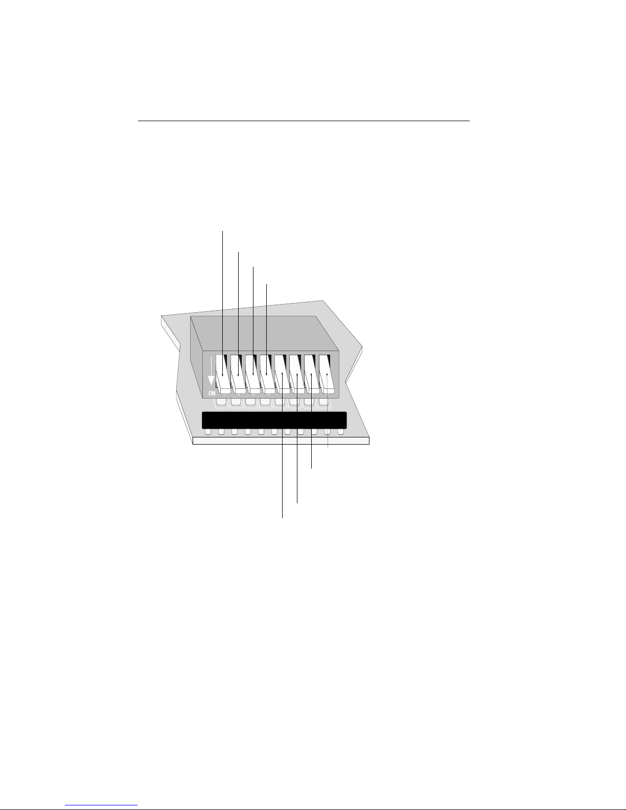
2.2.2 Setting Configuration Switches
Before installing your FDMMIM, you must set the bridge
configuration switches to select initial configuration options. Though
the modular switch bank holds eight switches, the FDMMIM utilizes
only a few of them. (See Figure 2-6.)
Note: At power-up, configuration switch settings override Local
Management settings. This means that when you cycle MMAC power
or reset the FDMMIM, LM settings default to their corresponding
configuration switch settings.
Locate the switch bank along the top edge of the FDMMIM and
FDMMIM-30 (Figure 2-5). On the FDMMIM-04 and FDMMIM-24,
the switch bank resides just below the daughter board containing the
M type ports.
LASER
Configuration
Switch
Set to LASER (on
FDMMIM-30 only)
JP6
LASER
JP6
FDMMIM
Laser
Front Panel
Jumper (JP6)
V
N
I
I
E
A
W
L
P
PMB 3.6B
B
S
A
E
T
I
JP1
T
R
E
ON
OFF
Battery
ON
OFF
JP1
ON
Battery
Jumper (JP1)
Figure 2-5. Battery Activation/Switch Bank Location
Battery
2-7
Page 25
INSTALLING THE FDMMIM
Figure 2-6 shows the general location of the switch bank and the
configuration switch options.
Note: The FDMMIM is shipped with all switches in the ON position.
1. ON - Forward broadcast packets
OFF - Filter broadcast packets
2. Not used
3. Not used
4. ON - Multimode Fiber
OFF - Single Mode Fiber
Note: Switch #4 does not affect
operation; this switch simply tells
LM whether it is a Multimode
or Single Mode board.
ON
1 2 3 4 5 6 7 8
2-8
8. ON - Normal
OFF - Manufacturing use only
7. BOOTP toggle switch
(for emergency boot-up, and
download use only -- see Chapter 6)
6. Not used
5. Not used
Figure 2-6. Configuration Switch Settings
Page 26

INSTALLING THE FDMMIM
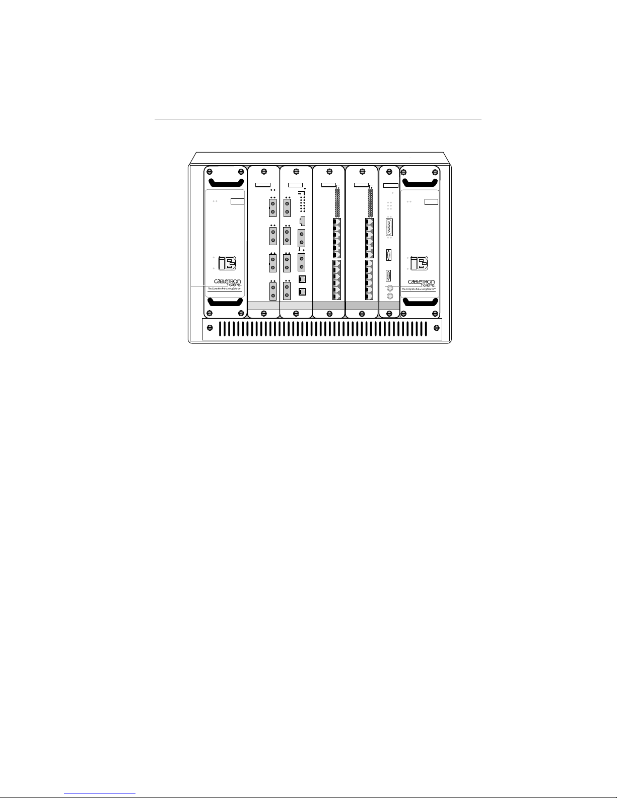
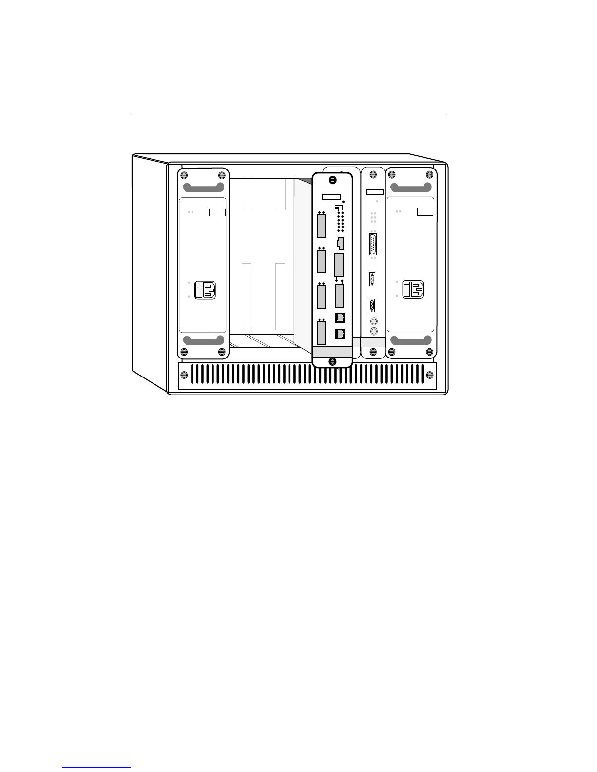
2.2.3 Installing into the MMAC
After configuring your MIMs, activating the FDMMIM battery, and
setting any FDMMIM configuration switches, proceed as follows:
Note: We recommend powering-down your MMAC before removing
FDMMIMs, even though these modules have “hot swap” capabilities.
1. Turn off the power to the MMAC. Remember that MMACs with
multiple power supplies have an On/Off switch for each supply.
2. Holding the FDMMIM by the front panel or by the edges of the
circuit board, align the bottom and top edges of the card with the
slot guides in the MMAC chassis. Be sure that both the bottom
and top edges of the card rest in the guide slots. (See Figure 2-7.)
3. Slide the FDMMIM into the MMAC until you feel it meet the
backplane. At this point, the front panel should be about 1/2 inch
from being flush with the rest of the modules in the MMAC.
4. Press gently to seat the module into the backplane. Do not try to
force the module into place or use the knurled knobs to draw the
module into the backplane. Forcing a misaligned module into
place can damage the FDMMIM or the MMAC backplane.
5. Once the module seats in the backplane, tighten the two knurled
knobs. This step is important. If you do not tighten the knurled
knobs, vibration can cause the module to lose contact with the
backplane and disrupt your network.
2-9
Page 27
INSTALLING THE FDMMIM
FOMIM-22
FDMMIM-04
SN
SN
POWER
FAIL
SN
OK
MMAC - 5PSM
OFF
ON
RESET
PWR
ENET
FDDI
LNKPOK
STBY
PWR
TWR
SYOK
XMT
XMT
TX
RCV
RCV
1
WRP
CLN
RX
ROP
POK
B
Y
TX
P
A
S
RX
LNK
POK
POK
POK
S
F
D
2
TX
D
I
RX
A
LINK
TX
LNK
RX
F
D
D
3
I
TX
B
RX
M
O
D
E
LNK
TX
M
RX
C
O
N
4
S
4
O
L
E
ETHERNET
FDDI
Figure 2-7. Installing the FDMMIM into the MMAC
2.3 CONNECTING FIBER OPTIC CABLING
IRM3
SN
RESET
POWER
FAIL
SN
BOK
RCV
POK
MMAC - 5PSM
C
O
N
S
OFF
O
L
E
ON
M
O
D
E
M
OK
PWR
MGMT
CLN
ON OFF
T
X
R
X
ETHERNET
You can install the FDMMIM as a Dual Attached Station (DAS),
with or without an optical bypass switch. Figure 2-8 illustrates the
main ring cabling to the FDDI A and B ports on the FDMMIM.
Figure 2-9 shows the duplex cable connections to the A and B ports.
When installed, the optical bypass switch connects in series between
the main ring connections and the FDMMIM. (For a summary of
FDDI connection rules, see Appendix C.)
2-10
Page 28
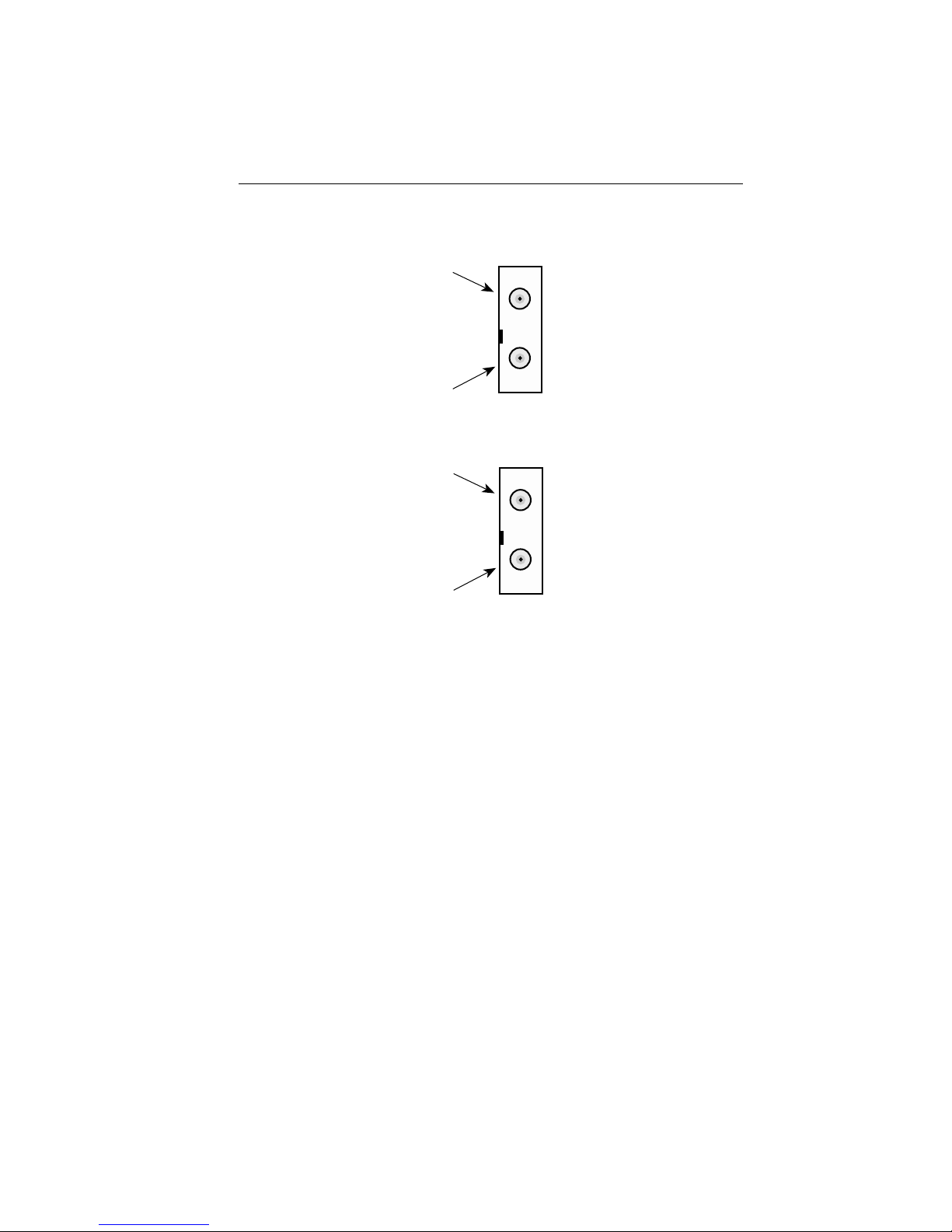
Primary In
Red Key
Secondary
Out
Secondary
In
Blue Key
Primary
Out
INSTALLING THE FDMMIM
F
D
D
I
A
F
D
D
I
B
Figure 2-8. FDMMIM Duplex Fiber Optic Receptacles
The Optical Bypass Switch (also known as a Station Bypass Switch
or a Bypass Relay) is an X3T9.5 compliant device that automatically
isolates the FDMMIM from the ring if the FDMMIM fails or the
FDMMIM power source fails. The bypass switch is optional. If you
use this optional device, you should remember the following:
• A bypass switch causes some signal loss which may cause
you to exceed the maximum allowable loss between stations.
• Bypass technology can protect only a small number of
consecutive bypassed stations. The exact number varies but
in a typical building environment, the maximum is three.
2-11
Page 29
INSTALLING THE FDMMIM
Secondary
Ring
Primary
Ring
Optical
Bypass
BYP ASS FDDI A FDDI B
Secondary
Ring
Primary
Ring
FDMMIM
Figure 2-9. FDMMIM Dual Ring Connections
Through a Bypass Switch
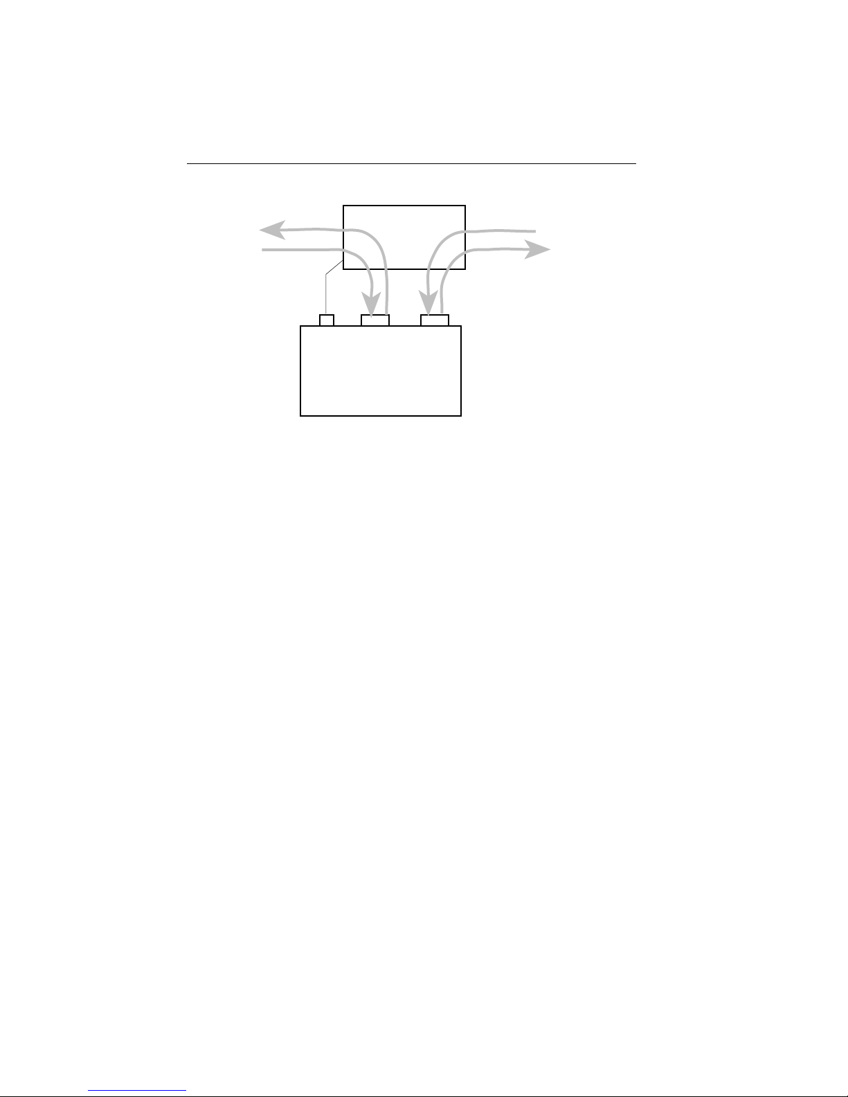
When installing an optical bypass switch, begin with steps 1 and 2
below to attach the duplex main ring cabling to the switch.
Otherwise, begin with step 3.
Note: If you install the bypass switch with the FDMMIM powered-up,
it can take up to five seconds before the FDMMIM recognizes the
switch.
1. Attach the main ring cables to the optical bypass switch by
inserting the A and B duplex connectors into their respective
keyed receptacles on the optical bypass switch.
2. Attach the small bypass cable connector at the FDMMIM Bypass
receptacle. Figure 2-10 shows the bypass switch cable
configuration.
3. Attach the Type A and Type B duplex connectors at their
respective FDDI receptacles (FDDI A and FDDI B) on the
FDMMIM front panel.
2-12
Page 30

INSTALLING THE FDMMIM
Enable-A
Enable-B
Ground
Ground
Bypass Present
Ground
1
2
3
4
5
6
Figure 2-10. Bypass Switch Cable Configuration
2.4 FDMMIM-04 AND FDMMIM-24 MASTER PORT CABLE
CONNECTIONS
The FDMMIM-04 and FDMMIM-24 have four M type concentrator
ports. The FDMMIM-04 ports are fiber connections (keyed green),
and the FDMMIM-24 ports are Unshielded Twisted Pair connections.
You can use these ports, to connect FDDI nodes, such as
workstations, to the dual ring. You can also attach M ports to the A
and B ports of another concentrator, to create a dual homing
(redundant concentrator) configuration (Refer to Appendix C, Basic
FDDI Networks, for additional information on dual homing).
2.5 TWISTED PAIR PINOUT CONFIGURATION
This section provides the RJ-45 pinout configuration for Unshielded
Twisted Pair (UTP) and Shielded Twisted Pair (STP) Physical Layer
Medium Dependent (PMD) ports. See Figure 2-11.
Note: When connecting two twisted pair ports together (e.g., an M
type port on an FDCMIM-24 to an F7069 Desktop Network Interface
(DNI) card.), a transmit and receive cross-over must occur between
the two devices (i.e., within the cable).
2-13
Page 31

INSTALLING THE FDMMIM
RJ-45 TP-PMD PORT
Contact Signal
Pin 1
1
2
3
4
5
6
7
8
Transmit +
Transmit —
N/A
N/A
N/A
N/A
Receive +
Receive —
Caution: Ground only one end of an
STP segment. For Cabletron TP-PMD
products, the port casing is grounded.
Figure 2-11. TP-PMD Port Pinouts
2.6 MASTER PORTS AND LANVIEW
Each master port has two LEDs — PST and LNK. These LEDs show
the status of that M type port.
PST (PORT STATUS)
This multi-state LED can indicate the following:
Green The station attached to the port is
2-14
connected to the network.
Page 32

INSTALLING THE FDMMIM
Amber Management has disabled this port.
Red or
Flashing Red The port has failed.
LED off The port has no valid connector attached.
LNK (MEDIA LINK OK)
When ON, this green LED indicates that a connection exists between
the M type port and the node at the other end of the port cable
segment. To ensure you maintain the link, the port generates an
idle signal when not transmitting data.
2.7 FDMMIM AND LANVIEW
LANVIEW gives you a window into the physical layer of your
network. The FDMMIM has two sets of system/bridge LEDs. One set
indicates activity on the Ethernet side of the bridge, the other set of
LANVIEW LEDs shows FDDI information.
2.7.1 Ethernet LEDs
Figure 2-11 shows the six Ethernet LEDs, identified as ‘ENET,’ on
the front panel of the FDMMIM.
ENET
FDDI
PWR
TWR
XMT
RCV
WRP
ROP
Figure 2-11. LANVIEW Ethernet LEDs
STBY
SYOK
XMT
RCV
CLN
POK
2-15
Page 33

INSTALLING THE FDMMIM
STBY (STANDBY)
When ON, this amber LED indicates that the FDMMIM is in
Standby mode. During power-up with STA disabled, the FDMMIM is
in Standby mode for approximately 15 seconds, learning addresses,
before going on line. During power-up with STA enabled, the bridge
progresses through the Listening state (sending and receiving
BPDUs), the Learning state (learning network addresses), and then
into the Forwarding state (receiving and forwarding data frames).
When the bridge goes to the Forwarding state, the STBY light is
turned OFF. STBY remains ON, and the bridge remains in the
Learning state, if there is at least one other parallel bridge in the
network serving as the root bridge.
SYOK (SYSTEM OK)
When ON, this green LED indicates that the FDMMIM has passed
all self tests.
XMT (TRANSMIT)
When ON, this green LED indicates that the bridge is transmitting
traffic to the Ethernet network. On a network with average traffic,
the XMT LED normally flashes.
RCV (RECEIVE)
When ON, this amber LED indicates that the bridge is receiving
Ethernet traffic. On a network with average traffic, the RCV LED
normally flashes.
CLN (COLLISION)
This red LED flashes when the bridge detects a collision or a jabber
packet on the Ethernet network.
POK (PORT OK)
When ON, this green LED indicates that the FDMMIM has passed
all of its Ethernet power-up diagnostic tests.
2-16
Page 34

INSTALLING THE FDMMIM
2.7.2 FDDI LEDs
Figure 2-12 shows the six FDDI LEDs on the front of the FDMMIM.
ENET
FDDI
PWR
TWR
XMT
RCV
WRP
ROP
Figure 2-12. LANVIEW FDDI LEDs
PWR (POWER)
When ON, this green LED indicates that the FDMMIM is receiving
power from the MMAC.
TWR (TWISTED RING )
When ON, this red LED indicates an undesirable cable connection.
TWR illuminates when you connect A to A or B to B instead of A to B
and B to A. The FDMMIM supports undesirable configurations.
(Appendix C summarizes FDDI connection rules.)
XMT (TRANSMIT)
STBY
SYOK
XMT
RCV
CLN
POK
When ON, this green LED indicates that the FDMMIM is
transmitting traffic to the FDDI network. On a network with
average traffic, the XMT LED normally flashes.
RCV (RECEIVE)
When ON, this amber LED indicates that the FDMMIM is receiving
FDDI traffic. On a network with average traffic, the RCV LED
normally flashes.
2-17
Page 35

INSTALLING THE FDMMIM
WRP (WRAP)
This red LED illuminates when the FDMMIM detects an FDDI ring
wrap, meaning that there is a break in the ring, and the system has
combined the primary and secondary rings into one ring.
ROP (RING OP)
When ON, this green LED indicates that the Token Claim Process
has completed successfully and the FDDI ring is operational.
2-18
Page 36

CONNECTING TO LOCAL MANAGEMENT
CHAPTER 3
CONNECTING TO LOCAL MANAGEMENT
Out-of-band management for the FDMMIM is called FDMMIM Local
Management. You can access this management tool by connecting a
terminal to the FDMMIM. This chapter explains:
• Connecting to Local Management with a terminal
• Logging-in to Local Management
• Monitoring the power-up diagnostic tests
• Manually resetting the FDMMIM.
3.1 CONNECTING A CONSOLE
Access LM through the RJ-45 CONSOLE port on the FDMMIM front
panel. This port supports asynchronous communication through a
Digital Equipment Corporation (DEC) VT220 or VT320 terminal, or
a PC emulation of one of these terminals.
A Console Cable Kit, included with your FDMMIM, contains cables
and adapters to connect the RJ-45 CONSOLE port to another RJ-45
port, a DB-9 port, or a DB-25 port of a terminal. Figure 3-1 shows
the pin configuration required for the console port.
You must properly configure your terminal to communicate with
Local Management. The following list provides the necessary setup
information for a VT220 or VT320 terminal. For more detailed setup
information, the keyboard map, or information on setting up a PC
emulation, refer to your specific terminal manual.
3-1
Page 37

CONNECTING TO LOCAL MANAGEMENT
If you have a VT220 or VT320 series terminal, press F3 (Set-Up) to
access the Setup Directory and set the options as follows:
Display Set-Up Menu
Columns 80 Columns
Controls Interpret Controls
Auto Wrap No Auto Wrap
Text Cursor No Cursor
General Set-Up Menu
Mode VT220, 7 Bit Control
VT320, 7 Bit Control
Cursor Keys Normal Cursor Keys
Communications Set-Up Menu
Transmit Transmit = 9600
Receive Receive = Transmit
XOFF XOFF at 64
Bits Parity 8 Bits, No Parity
Stop Bit 1 Stop Bit
Local Echo No Local Echo
Port VT220 — EIA Port, Data Leads Only
VT320 — DEC-423, Data Leads Only
Transmit Any option
Auto Answerback No Auto Answerback
Keyboard Set-Up Menu
Keys Typewriter Keys
Auto Repeat Any option
Keyclick Any option
Margin Bell No Margin Bell
Warning Bell Warning Bell
3-2
Page 38

CONNECTING TO LOCAL MANAGEMENT
1
C
O
N
S
O
L
E
2
3
4
5
6
FDDI
7
8
CONSOLE PORT
Pin 1 Transmit data (XMT) from CONSOLE port
Pin 2 Data set ready (DSR) to CONSOLE port
Pin 3 Not used
Pin 4 Receive data (RCV) to CONSOLE port
Pin 5 Signal ground (GND)
Pin 6 Data terminal ready (DTR) from CONSOLE port
Pin 7 Not used
Pin 8 Not used
Figure 3-1. CONSOLE Port Pin Configuration
To access Local Management:
1. Using the components of the Console Cable Kit, connect the
RJ-45 end of the RS-232 cable to the port labeled CONSOLE
on the FDMMIM.
2. Connect the other end of the RS-232 cable into the COMM
port on the terminal or a communication port on a PC. The
Console Cable Kit contains adapters to connect to either a
DB-9 or DB-25 port.
3. Turn on the terminal. After it warms up, press the RETURN
key. If you are connecting to a PC, load and run the terminal
emulation software. Start the program and press RETURN.
3-3
Page 39

CONNECTING TO LOCAL MANAGEMENT
Note If you turn on the FDMMIM while you are viewing Local
Management, you first see the FDMMIM power-up diagnostics, and
then the Password screen appears. If the FDMMIM is already on, the
Password screen appears.
4. Enter your password. (The default password is the RETURN
key. Section 6.2, The Community Names Table Screen,
explains how to change your password.)
5. Press the RETURN key. The System Information screen
appears. The System information screen is the starting point
for all Local Management functions.
3.2 POWERING-UP THE FDMMIM: DIAGNOSTIC TESTS
When you turn on the power to the MMAC, or press RESET on the
FDMMIM front panel, the FDMMIM runs thirteen diagnostic tests.
If your Local Management console is on, the FDMMIM displays the
results of each test. If a test fails, Local Management stores that
result in the Message Log. If any test fails, you should contact
Cabletron Systems Technical Support. Here is a brief description of
each FDMMIM diagnostic test.
CHECKSUM TEST
When you power-up the FDMMIM, the code downloads from Flash
memory to local RAM memory. While downloading, the FDMMIM
adds up all of the bytes of code and saves them as a 32 bit checksum.
The checksum test essentially compares this calculated 32 bit
checksum with the factory embedded checksum. Any difference
between the two sums flags the code as corrupted, and the test fails.
LOCAL RAM/SHARED RAM TESTS
The FDMMIM generates an extensive series of data patterns to fully
test the on-board memory chips.
3-4
Page 40

CONNECTING TO LOCAL MANAGEMENT
FDDI PORT A/B TESTS
When the FDMMIM transmits or receives frames via the primary or
secondary FDDI network ring, the frames must pass through the
FDMMIM A or B ports. The FDDI A and B tests check the hardware
components that control communications through the FDMMIM A
and B ports. No signals are transmitted to the network dual ring.
FNB TEST
FNB is the Flexible Network Bus, the data pathway within the
MMAC hub. This test checks the FDMMIM hardware components
that handle communications with the FNB. No signals are actually
transmitted to the FNB.
FDDI TESTS
After a frame enters the FDMMIM Port A, Port B, or the FNB, it
enters the Media Access Control (MAC) circuitry. The FDDI tests (1,
2, 3, and Loopback) check the FDMMIM internal data paths.
ETHERNET PORT SELF TEST
This test checks the internal data paths used by a frame that enters
the FDMMIM through the Ethernet port. This test does not
transmit any signal onto the network.
HARDWARE FILTER TEST
The bridge filter functions are rooted in hardware components to
maximize bridge performance. The hardware filter test checks these
filtering components.
INLINE FILTER TEST
When the inline filter receives frames on the FDDI port that require
filtering, it uses the other FDMMIM filtering components to
accomplish the task. This test generates several frames to test the
filtering function of the hardware components.
3-5
Page 41

CONNECTING TO LOCAL MANAGEMENT
3.3 MANUALLY RESETTING THE FDMMIM
In the event your device is not operating properly, or you want to
clear and reload RAM with the code in FLASH memory, you may
want to reset the FDMMIM. To accomplish this:
1) Take a paper clip (the 2 inch type works best).
2) Bend one length so that it sticks out. (See Figure 3-2.)
3) Press the straightened paper clip end into the RESET hole at
the top of the FDMMIM front panel.
After depressing the microswitch in the RESET hole, the FDMMIM:
• Ceases operation
• Clears the contents of RAM
• Downloads the code in FLASH memory to RAM
• Runs its power-up diagnostic tests.
Resetting the FDMMIM has the same effect as turning the MMAC
power off and on, except that it does not affect any of the other
modules in the MMAC.
3-6
FDMMIM
SN
RESET
STBY
XMT
RCV
WRP
Figure 3-2. Resetting the
STBY
SYOK
?
XMT
RCV
CLN
?
POK
FDMMIM
Page 42

GETTING STARTED WITH FDMMIM/LM
CHAPTER 4
GETTING STARTED WITH FDMMIM
LOCAL MANAGEMENT
This chapter explains:
• Format conventions used in this manual
• The organization of Local Management screens
• Screen header fields, and what special header fields exist in
certain Local Management screens
• Local Management default values, and where you can change
these values.
4.1 UNDERSTANDING THE SCREENS AND COMMANDS
Local Management lets you control FDMMIM bridge parameters and
ports of adjacent FDDI modules. To change a setting:
• Open the appropriate screen
• Highlight a field
• Type in the new information, or use the RETURN key to
toggle between available field choices.
Local Management screens displayed in this manual use the
following format conventions:
• Menu choices and commands appear UPPER CASE BOLD.
Note: Fully underlined words indicate a title or category.
They are not menu choices or commands.
• Fields that you can alter appear shaded.
4-1
Page 43

GETTING STARTED WITH FDMMIM/LM
4.2 USING THE MANAGEMENT KEYBOARD
Use the keyboard arrows (up, down, left, and right) to highlight a
command or field (you can only highlight changeable fields). Local
Management rejects an incorrect entry, and displays a message that
explains the problem. (Refer to Appendix A for explanations of
specific Warning and Error Messages.)
To make a menu selection:
• Highlight the menu selection, and then press the RETURN
key on the keyboard.
To alter a field:
• Highlight the field, type the new information, and then press
the RETURN key on the keyboard.
To toggle a field (choose an alternate selection for a field):
• Highlight the field, and then press the RETURN key on the
keyboard until the selection you want appears.
Note: When you make changes to screen fields, be sure to execute the
SAVE command before you exit from the screen.
Here are a few navigation hints to remember.
• The TAB key performs the same function as the right arrow.
• Backspace permits correction of entries.
• Most screens present RETURN as a command selection to
return to the previous screen. RETURN is normally
highlighted as the default command choice in a screen.
4.3 NAVIGATING THROUGH LOCAL MANAGEMENT
The first screen you see after you log on to Local Management is the
SYSTEM INFORMATION screen. The SYSTEM INFORMATION
screen is the main menu and starting point for all other screens and
commands. Figure 4-1 shows the organization of Local Management.
4-2
Page 44

GETTING STARTED WITH FDMMIM/LM
PASSWORD SCREEN Access FDMMIM Local Management screens.
SYSTEM INFORMATION View FDMMIM status and network
activity; Access all major LM screens.
MESSAGE LOG History log showing warning and error
messages reported by LM.
NETWORK TRAFFIC Ethernet and FDDI packet
counters. Editing limited to resetting counters.
FDDI CONFIGURATION Display and control FDDI
modules within the hub.
FILTERING DATABASE Display/Create/Delete acquired
and permanent database entries.
SPECIAL DATABASE Store up to 10 additional
filter entries.
BRIDGE PROTOCOL Set Spanning Tree Algorithm bridge
parameters.
BRIDGE PORT PARAMETERS View port-specific
parameters; Adjust Port Priority/ Path Cost.
RING MAP View logical map of active FDDI addresses.
NODE INFORMATION View parameters for
individual nodes on the FDDI ring.
SETUP Set FDMMIM operating parameters; Enable or
disable bridge; Reset databases.
COMMUNITY NAMES Set permission levels for
local and remote access.
TFTP DOWNLOAD Set conditions for updating
LM firmware.
TRAP TABLE Send trap information to specific
IP addresses.
Figure 4-1. FDMMIM Local Management Structure
4.4 SCREEN ORGANIZATION
4-3
Page 45

GETTING STARTED WITH FDMMIM/LM
Note: Other chapters that refer to specific screens do not repeat this
information.
Appearing in All Screens
Date and time displays the FDMMIM date and time. To change the
date and time, go to the Setup screen.
Title describes the screen purpose, such as SETUP, or the type of
information that the screen provides, such as NETWORK TRAFFIC.
Just below the title line is an unlabeled blank line called the
Message Bar. The Message Bar is empty unless Local Management
is displaying a message, warning, or error. (Chapter 5, Using the
Information Screens, describes Messages, Warnings, and Errors in
detail. Appendix A explains each Local Management Warning and
Error.) The Message bar display remains on the screen for a short
period and then disappears. (You can edit the Message Bar display
duration in the Setup screen.) All Error and Warning messages not
relating to station management are saved in the Message log.
Appearing in Most Screens
The Ethernet Address is a unique factory set address for the
FDMMIM Ethernet Port, shown in canonical format.
The FDDI Address is a unique factory-set address for the
FDMMIM’s FDDI port, shown in MAC format.
Uptime shows the elapsed time since the bridge was last turned on
(MMAC power cycled) or restarted using the RESET button.
Ring State indicates the status of the FDDI ring. The possible ring
state conditions are:
Ring-Op The ring is functioning correctly.
Isolated The bridge is not attached to the ring.
Non-Op The bridge is attempting to enter the
ring.
4-4
Page 46

GETTING STARTED WITH FDMMIM/LM
Detect The claim (beacon) process of the
FDDI ring protocol has exceeded 1
second. There may be a problem.
Non-Op-Dup The ring failed to complete the claim
(beacon) process. This usually
indicates a duplicate FDDI address.
Ring-Op-Dup The ring is operational, but a
duplicate FDDI address may be
present somewhere on the network.
Directed The claim (beacon) process did not
complete within 10 seconds. The
bridge is sending directed beacons to
indicate a problem.
Trace A problem has been detected with the
FDMMIM or its nearest upstream
neighbor. A trace is being sent to
notify the nearest upstream neighbor
of the problem.
Status/Bridge Status indicates the current status of the FDMMIM.
Three potential status conditions could appear in this field:
On-Line The FDMMIM is fully operational.
Standby In Standby with STA enabled, the
FDMMIM bridge is learning address
information but is not forwarding
frames. Standby usually indicates
that the bridge is not the root bridge
in a parallel bridge network.
Disabled The bridge is disabled (refer to Setup
screen, ENABLE/DISABLE
command). While disabled, the bridge
is not learning address information
and no traffic is being forwarded.
4-5
Page 47

GETTING STARTED WITH FDMMIM/LM
Appearing in the System Information Screen Only
FW Version refers to the version of Local Management software
currently installed on the FDMMIM. The Local Management
software is stored in FDMMIM FLASH memory. FLASH memory
allows you to download new software using the FDMMIM/LM TFTP
Download screen or a remote management tool such as Cabletron
Systems Remote LANVIEW/Windows.
The IP Address is the Internet Protocol address. The default is
0.0.0.0. You can edit the IP address in the Setup screen.
Message Log displays how many Errors the Message Log currently
holds. If the Message Log contains any Errors, the Message Log field
blinks.
Caution: Errors are the most severe class of message. They usually
indicate a hardware malfunction or some condition impacting
network service.
Appearing in the Setup Screen Only
Bridge Name, a changeable text field, shows the user-assigned
name for the bridge. The bridge name helps a network manager
identify the bridge using a remote management tool. The default
bridge name is Cabletron Enet - FDDI Bridge.
Location, a changeable text field, shows a user-defined description
of the bridge’s physical location. The Location helps a network
manager identify bridge location using a remote management tool.
The default location is Local.
Last Reset provides the date and time the FDMMIM was last reset.
Restarts provides the number of times the FDMMIM has
experienced a restart/power cycle since its battery was enabled.
4.4.2 Data Sections and Command Menus
Each Local Management screen contains data and commands
specific to the function of that screen. Refer to specific screen
chapters for detailed data and command information.
4-6
Page 48

GETTING STARTED WITH FDMMIM/LM
4.5 SETTING FDMMIM OPERATING PARAMETERS
Tables 4-1 and 4-2 list, in alphabetical order, each changeable
FDMMIM parameter. In addition, the tables also provide the default
setting, allowed range, and name of the Local Management screen
where you can edit the parameter.
The parameters in Table 4-1 all reset to their default values when
you execute the RESTORE DEFAULT SETTINGS command in the
Setup screen. The parameters in Table 4-2 remain unchanged when
you restore defaults.
Parameter Default (Range) Edit Screen
Bridge Forward Delay 15 seconds (4 to 30 sec.) Bridge Protocol
Bridge Hello Time 2 seconds (1 to 10 sec.) Bridge Protocol
Bridge Max. Age 20 seconds (6 to 40 sec.) Bridge Protocol
Bridge Name Cabletron Enet-FDDI Setup
Bridge (up to 32 chars.)
Bridge Priority 8000 (0 to FFFF) Bridge Protocol
Chassis Type MMAC 8 (MMAC 3, 5, 8) Setup
Dynamic Ageing Time 300 seconds Filtering
(10 to 1000000 sec.) Database
FDMMIM Slot Location Slot 2 (Slot 2 through 8) Setup
Location Local (up to 32 chars.) Setup
Message Duration Time 2 seconds (1 to 999 sec.) Setup
Net Name LAN_1 (up to 32 Setup
LAN_2 chars.)
Path Cost Enet Port - 100 (1 to 65535)Bridge Port
FDDI Port - 10 (1 to 65535)Parameters
Port Name Ethernet Port (up to 32 Setup
FDDI Port chars.)
Port Priority Enet port - 80 (0 to FF) Bridge Port
4-7
Page 49

GETTING STARTED WITH FDMMIM/LM
FDDI port - 80 (0 to FF) Parameters
Screen Refresh Time 2 seconds (1 to 999 sec.) Setup
Type of STA Protocol 802.1 (802.1, DEC, None) Setup
Table 4-1. FDMMIM Defaults
Parameter Default (Range) Edit Screen
Community Names Basic Read - public Community
Read Only - public Names
Read Write - public
Superuser - RETURN key
(up to 32 chars.)
Date None (MM/DD/YY) Setup
IP Address 0.0.0.0 Setup
(0.0.0.0 to 255.255.255.255)
Password RETURN key Community
(up to 32 chars.) Names
Subnet Mask 255.255.0.0 Setup
(0.0.0.0 to 255.255.255.255)
Time None (HH:MM:SS) Setup
Table 4-2. FDMMIM Defaults
4-8
Page 50

USING THE INFORMATION SCREENS
CHAPTER 5
USING THE
INFORMATION SCREENS
This chapter concentrates on the data sections and command menus
of the Local Management information screens. These screens
provide status information on FDMMIM functions. This chapter
includes data and command information on the following screens:
• System Information
• Network Traffic
• Ring Map
• Node Information
• Message Log
You can reset port counters and delete the message log, but you
cannot edit any of the individual fields in the information screens.
5.1 THE SYSTEM INFORMATION SCREEN
The System Information screen is the first screen you see after you
successfully log on to Local Management. This screen does not have
any fields that you can update. It is strictly a status screen, an
overview of general settings and network activity. However, the
System Information screen provides the starting point for access to
all other FDMMIM/LM screen displays and commands.
Four blocks of data, NETWORK TRAFFIC, FDDI, FILTER
DATABASE, and BRIDGE PROTOCOL, make up the data section of
the System Information screen. The title of each section is a part of
the Command Menu, providing access to their associated screens.
(See Figure 5-1.)
5-1
Page 51

USING THE INFORMATION SCREENS
04/02/94 08:43:18 SYSTEM INFORMATION FW Version: 3.00.00
Ethernet Address: 00-00-1D-06-F9-C2 Bridge Status: On-Line
FDDI Address: 00-00-B8-60-9F-C3 Uptime: 10 Days 12 Hours 23 Minutes
IP Address: 134.141.30.14 MESSAGE LOG: 22
NETWORK TRAFFIC FILTER DATABASE
Frames Received: 1257 Type of Filtering: IEEE
Frames Filtered: 1258 Dynamic Ageing Time: 300
Frames Forwarded: 1257 Dynamics: 7652
Frames Transmitted: 0 Statics: 1134
Frame Errors: 0
FDDI BRIDGE PROTOCOL
Ring State: Ring-Op Type of STA Protocol: 802.1
Ring Op Count: 1 Ethernet Port: FORWARDING
MAC Configuration: Through-A FDDI Port: FORWARDING
Tneg: 83 Bridge Priority: 8000
Tnotify: 30 Desig. Root: 80-00-00-00-1D-06-A4-D2
Master Port Count: 4
RING MAP SETUP EXIT
Figure 5-1. System Information Screen
5.1.1 NETWORK TRAFFIC Data
NETWORK TRAFFIC gives you a summary of frame activity since
the last time the FDMMIM was reset or the counters cleared. Traffic
statistics ignore frame type (Ethernet or FDDI). See section 5.2 for
information on the Network Traffic screen.
The System Information screen provides the following NETWORK
TRAFFIC information:
Frames Received displays the total number of frames received by
the FDMMIM at both the FDDI and Ethernet ports.
Frames Filtered displays the total number of frames that were not
passed from one bridge port to the other because the frame’s
destination was located on the same network as its source.
Frames Forwarded displays the total number of frames that have
been forwarded from one network to the other (FDDI to Ethernet
and Ethernet to FDDI).
5-2
Page 52

USING THE INFORMATION SCREENS
Frames Transmitted displays the total number of frames
transmitted by the FDMMIM (for example, Bridge Protocol Data
Unit (BPDU) frames, FDDI SMT frames, etc.).
Frame Errors is the total number of errors detected by the
FDMMIM at both ports. The individual errors that comprise this
total are displayed in the Network Traffic screen.
5.1.2 FDDI Data
The System Information screen displays top level information about
the FDMMIM FDDI concentrator. See Chapter 9, Controlling
Concentrator Modules and Ports, for information on the FDDI
Configuration screen. The System Information screen provides the
following FDDI information:
Ring State shows the current ring state. Refer to Chapter 4,
Getting Started with FDMMIM/LM, for possible ring state
conditions and their definitions.
Ring Op Count keeps track of the number of times the FDDI ring
has initialized since the last time the FDMMIM was reset. If this
number grows steadily, it means that the ring is unstable.
MAC Configuration describes the current configuration of the
MAC and physical layers of the A and B ports. Here are the possible
port configurations:
Through-A The primary ring is connected to the
MAC (from PHY-A/Primary In to
MAC to Primary Out/PHY-B). The
secondary ring is isolated from the
MAC (from PHY-B Secondary In to
PHY-A Primary Out).
THROUGH-A
Note: Dotted line
indicates unused
path or connection.
PRIMARY
IN
FDDI-A
SECONDARY
OUT
MAC
PRIMARY
OUT
FDDI-B
SECONDARY
IN
5-3
Page 53

USING THE INFORMATION SCREENS
Wrap-A PHY-A is wrapped via the MAC
(from PHY-A/Primary In to MAC to
Secondary Out/PHY-A). PHY-B is
disconnected.
WRAP-A
PRIMARY
OUT
FDDI-B
SECONDARY
IN
Note: Dotted line
indicates unused
path or connection.
PRIMARY
IN
FDDI-A
SECONDARY
OUT
MAC
Wrap-B PHY-B is wrapped via the MAC (from
PHY-B/Secondary In to MAC to
Primary Out/PHY-B). PHY-A is
disconnected.
WRAP-B
Note: Dotted line
indicates unused
path or connection.
PRIMARY
IN
FDDI-A
SECONDARY
OUT
MAC
PRIMARY
OUT
FDDI-B
SECONDARY
IN
Isolated Both PHY-A and PHY-B are isolated
from the ring.
ISOLATED
Note: Dotted line
indicates unused
path or connection.
PRIMARY
IN
FDDI-A
SECONDARY
OUT
MAC
PRIMARY
OUT
FDDI-B
SECONDARY
IN
5-4
Page 54

USING THE INFORMATION SCREENS
Wrap-AB PHY-B is connected to the MAC (from
PHY-B/ Secondary In to MAC to
Primary Out/PHY-B). PHY-A is
wrapped Primary In to Secondary
Out), isolating PHY-A from the MAC.
WRAP-AB
PRIMARY
IN
FDDI-A
SECONDARY
OUT
MAC
PRIMARY
OUT
FDDI-B
SECONDARY
IN
Tneg (Time Negotiated) is the negotiated token rotation time (in
milliseconds) that devices on the ring establish through the token
claiming process.
Tnotify is the interval (in seconds) at which an FDMMIM transmits
Neighbor Information Frames (NIFs). The station uses NIFs to
periodically announce its address and basic station description.
Master Port Count shows the number of available M type ports.
5.1.3 FILTER DATABASE Data
The FILTER DATABASE section of the System Information screen
describes the Acquired and Permanent Database. In addition, this
screen provides access to the Filter Database screen, Create Filter
Entry screen, Delete Filter Entry screen, and Special Database
screen. The FILTER DATABASE section of the System Information
screen displays the following information:
Type of Filtering is IEEE, Special, or Both. The bridge reads each
packet’s source address and adds it to the Acquired Database (if it is
not already there). Next, the bridge checks the packet’s destination
address to determine whether or not to forward the packet.
5-5
Page 55

USING THE INFORMATION SCREENS
Dynamic Ageing Time is the length of time that the Acquired
Database retains an address before purging it. You can set the
Dynamic Ageing Time in the Filter Database screen to any value
between 10 and 1 million seconds.
Dynamics are those addresses that the bridge learns from network
traffic. The FDMMIM does not retain Dynamic entries in its
memory, in the event it loses power, is turned off, or is reset.
Statics are addresses that the FDMMIM copies from the Permanent
Database to the Acquired Database when the Acquired Database
initializes. Static entries remain in memory when the FDMMIM
loses power, is turned off, or is reset.
5.1.4 BRIDGE PROTOCOL Data
The BRIDGE PROTOCOL section of the System Information screen
describes the Spanning Tree Algorithm (STA). This section also
provides access to the Bridge Protocol screen and Port Parameters
screen where you can edit the Spanning Tree settings.
STA is the method that bridges use to decide which bridge is the
controlling (Root) bridge when 2 or more bridges exist in parallel.
You can control STA through the Setup screen and the Bridge
Protocol screen.
The following lists information in the BRIDGE PROTOCOL section:
Type of STA Protocol choices (IEEE 802.1, DEC, or None). You
can select the STA protocol type in the Setup screen. (Default =
IEEE 802.1.)
Caution: All bridges in a network must use the same Spanning Tree
protocol. The 802.1 and DEC protocols have unique formats for their
Bridge Protocol Data Units (BPDU). Trying to mix STA protocols
results in an unstable network.
5-6
Page 56

USING THE INFORMATION SCREENS
Ethernet Port and FDDI Port display the port state of the
respective bridge ports. The possible port states include:
DISABLED Management has disabled this port.
No traffic can be received or
forwarded while the port is disabled.
LEARNING The bridge is learning network
addresses. The bridge enters the
Learning state when the Acquired
Database is being created (during
start-up or after being deleted), or
when the Spanning Tree Algorithm
detects a network topology change.
LISTENING The bridge is not adding information
to the Filtering Database. The bridge
is monitoring BPDU traffic while
preparing to move from the Learning
to the Forwarding state.
FORWARDING The bridge is on-line and this port is
forwarding traffic.
BLOCKING The port will not forward any traffic
through the bridge.
Bridge Priority displays the part of the bridge address containing
the identifier. Spanning Tree uses this identifier for priority
comparisons. You can adjust the bridge priority in the Setup screen.
The lower the number, the higher the priority. (Default = 8000.
Allowable range = 0 - FFFF.)
Desig. Root displays the unique bridge identifier for the bridge that
is assumed to be the Root. The bridge identifier value is computed
from the bridge’s address and its bridge priority value.
5-7
Page 57

USING THE INFORMATION SCREENS
5.1.5 System Information Screen Commands
The System Information screen is the starting point for any activity
in Local Management. The System Information screen contains the
following commands:
MESSAGE LOG opens the Message Log screen to display all
messages, warnings, and errors reported by Local Management. The
Message Log can hold up to 10 messages. Editing is limited to
deleting all existing log entries.
NETWORK TRAFFIC opens the Network Traffic screen to display
information about both the Ethernet and FDDI bridge ports. This
screen provides a complete breakdown of the data displayed in the
NETWORK TRAFFIC section of the System Information screen.
Editing is limited to resetting the counters.
FDDI opens the FDDI Configuration screen to display a graphic
representation of the FDDI concentrator ports, including other FDDI
concentrator modules (FDCMIMs) that reside in adjacent MMAC
slots. The FDDI Configuration screen lets you enable and disable
concentrator modules and individual M type ports.
FILTER DATABASE gives access to the screen where you display
entries in the Acquired, Permanent, and Special Databases.
BRIDGE PROTOCOL gives access to the Bridge Protocol and Port
Parameters screens, where you control the Spanning Tree Algorithm
operational parameters.
RING MAP displays a graphic representation of the FDDI ring
topology. The map shows the address, device type, and cable
configuration of each station on the ring. The RING MAP screen
also provides access to a NODE INFORMATION screen for each
device on the ring.
SETUP is where you set general bridge configuration parameters.
This screen also provides access to the Community Names Table
screen, Trap Table screen, and TFTP Code Download Setup screen.
EXIT ends the Local Management session, and returns you to the
Password screen.
5-8
Page 58

USING THE INFORMATION SCREENS
5.2 THE NETWORK TRAFFIC SCREEN
The Network Traffic screen provides a detailed breakdown of the
information provided in the Network Traffic section of the System
Information screen.
Below the header information (described in Chapter 4), the Network
Traffic screen data section shows frames and error counts for both
the Ethernet port and the FDDI port.
To display the Network Traffic screen:
• Highlight the NETWORK TRAFFIC command in the System
Information screen, and press RETURN.
04/02/94 08:43:23 NETWORK TRAFFIC
Ethernet Address: 00-00-1D-06-F9-C2 Ring State: Ring-Op
FDDI Address: 00-00-B8-60-9F-C3 Status: On-Line
ETHERNET FDDI
% FRAMES % BRIDGE MGMT SMT
Received 204451 1728 0 0
Filtered 53 109214 100 1728 + 0
Forwarded 93134 0 0
Transmitted 2 71521 1846
Ethernet Exceptions FDDI Exceptions
Rx CRC 0 Rx Errors 0 0 0
Rx Overflow 0 Rx Overflow 0 0 0
Rx Oversize 0 Rx IP Frag Err 0 0 0
Rx Alignment 0
Tx Abort 0 Tx Abort 0 0
Tx Overflow 0 Tx Overflow 0 0
TX Collision 0 Tx Ring Down 27871 757
RETURN RESET COUNTERS
Figure 5-2. Network Traffic Screen
5-9
Page 59

USING THE INFORMATION SCREENS
5.2.1 Network Traffic Screen Data
The Network Traffic screen displays the following:
Received shows the total number of frames received by the
FDMMIM at each bridge port. The totals include both data and
Bridge Protocol Data Unit (BPDU) frames.
Filtered shows the total number of frames NOT passed from one
bridge port to the other, because the frame’s destination was located
on the same network as its source. If a bridge port is not in the
Forwarding state, it filters all data frames it receives at that port.
A small plus sign (+) may appear just to the right of the FDDI
filtered frame number for the FDDI bridge (see Figure 5-1). This sign
indicates the FDMMIM software, while performing other functions,
may have lost track of the total number of filtered frames. The
FDMMIM displays a continuation from the last “known” number of
filtered frames. To clear the plus sign, reset the counters.
Forwarded shows the total number of frames forwarded from one
network to the other (Ethernet to FDDI or FDDI to Ethernet).
Transmitted shows the total number of SMT and BPDU frames
sent by the FDMMIM from each port.
Ethernet/FDDI Exceptions shows the total number of frames
discarded by the bridge for any reason. The following describes
exception frames further:
Rx CRC Shows the number of frames received
(Ethernet only) at the Ethernet port with a bad
Cyclical Redundancy Check (CRC)
field. A frame with a bad CRC field
usually indicates that the frame was
damaged in transmission.
Rx Errors Combines the number of frames with
(FDDI only) a bad Cyclical Redundancy Check
(CRC) and misaligned packets
received at the FDDI port.
5-10
Page 60

USING THE INFORMATION SCREENS
Rx Overflow Shows the number of frames lost due
to a lack of buffer memory space. An
overflow condition is usually due to a
high traffic level and collision rate on
the Ethernet network. The bridge’s
buffer memory space fills while the
bridge is waiting to make valid
transmissions to the Ethernet or
FDDI LAN. The only remedy is
reducing the collision rate on the
Ethernet LAN.
Rx Oversized Shows the number of received frames
(Ethernet only) that have more than 1,518 data bytes
(not including the preamble), the
IEEE 802.3 maximum.
Rx IP Frag Err Shows the number of frames the
(FDDI only) FDDI port could not fragment for
transfer to Ethernet. Possible causes:
• The frame was too large for
unfragmented transfer, and was
not using IP network protocol.
• Fragmentation was not allowed.
• The IP frame header failed its
checksum test prior to attempting
fragmentation.
Rx Alignment Shows the number of misaligned
(Ethernet only) frames received by the Ethernet port.
Tx Abort Shows the number of transmissions
that were aborted because of a
transmit error.
Tx Collision Shows the number of collisions detect(Ethernet only) ed at the Ethernet port.
5-11
Page 61

USING THE INFORMATION SCREENS
Tx Overflow Shows the number of frames lost at
transmission, due to a lack of
transmit queue memory space. An
overflow condition is usually due to a
high traffic level and collision rate at
the Ethernet interface, or a problem
on the FDDI ring.
Tx Ring Down Shows the number of frames lost
(FDDI only) from the inability of the bridge to
transmit frames onto a non-operating
FDDI ring.
5.2.2 Network Traffic Screen Commands
RETURN closes the Network Traffic screen, and returns you to the
System Information screen.
RESET COUNTERS sets all counters within the bridge to zero.
Note: When you reset the counters, you reset ALL Local Management
counters to zero, including those displayed on the System Information
screen. This also affects the information displayed by an SNMP
remote management tool, since the FDMMIM is the source for MMAC
FDDI information.
5-12
Page 62

USING THE INFORMATION SCREENS
5.3 THE RING MAP SCREEN
The FDDI Ring Map screen shows FDDI formatted addresses of ring
stations in a graphic illustration of the FDDI ring topology, and
provides access to a Node Information screen for each device.
To display the Ring Map:
• Highlight RING MAP in the System Information screen, and
press RETURN.
04/02/94 08:44:34 FDDI RING MAP
Ethernet Address: 00-00-1D-06-F9-D6 Ring State: Ring-Op
FDDI Address: 00-00-B8-60-9F-EB Status: On-Line
Uptime: 10 Days 22 Hours 01 Minutes
FDDI Port: 00-00-B8-60-9F-EB Address Mode: MAC MAC Count: 3
00-00-B8-60-9F-EC (DAC) <<<<<<<<<<<<<<<<< (DAC) 00-00-B8-40-02-92
00-00-B8-C0-E1-F0 (DAS) >>>>>>>>>>>>>>>>^
RETURN CHANGE ADDRESS MODE SCROLL DOWNSTREAM 1 SCROLL UPSTREAM 1
Figure 5-3. FDDI Ring Map Screen
Under some conditions the display must remain on the screen for at
least 30 seconds to accurately reflect ring configuration. A neighbor
time-out can take as long as 228 seconds to update on the ring map.
5-13
Page 63

USING THE INFORMATION SCREENS
5.3.1 Ring Map Screen Data
The FDDI Ring Map shows the address and sequence of each FDDI
device attached to the ring. When first displayed, the station at the
upper left corner of the ring is this station (FDMMIM). The screen
displays node class, node address, and twisted and/or wrapped
conditions (T for twisted and/or W for wrapped) in parentheses. The
following lists the node class possibilities:
NAS (Null Attached Station) Isolated
station; station not connected to an
FDDI ring.
DAS (Dual Attached Station) Station that
does not support M ports, but
connects directly to an FDDI primary
and secondary ring using A and B
ports.
DAC (Dual Attached Concentrator) Station
that supports M ports and connects
directly to an FDDI primary and
secondary ring using A and B ports.
SAS (Single Attached Station) Station that
accesses the main ring through a
concentrator, creating a ring of trees
topology.
SAC (Single Attached Concentrator)
Station that accesses the main ring
through another concentrator and, in
turn, allows the connection of more
devices. SACs provide the same
connections as DACs, without
attaching to the dual ring.
While LM updates the map, for example, during a ring topology
change, the screen shows ??-??-??-??-??-?? to illustrate an
undetermined address. You cannot use the scroll commands until
LM finishes rebuilding the map.
Note: The Ring Map display stops at the first occurrence of an
undetermined address, and does not display any known information
beyond this point.
5-14
Page 64

USING THE INFORMATION SCREENS
5.3.2 Ring Map Screen Commands
RETURN closes the Ring Map screen, and returns you to the
System Information screen.
CHANGE ADDRESS MODE lets you switch between canonical or
MAC format addresses. The Address Mode toggles each time you
execute this command.
SCROLL DOWNSTREAM n rotates the ring display, so that the
station addresses shift around the ring in a clockwise direction. The
n controls the number of shifts upstream. If the Ring Map contains
only one node, scroll commands are not displayed.
SCROLL UPSTREAM n rotates the ring display, so that the
station addresses shift around the ring in a counterclockwise
direction. The n controls the number of shifts upstream. If the Ring
Map contains only one node, scroll commands are not displayed.
5.3.3 Adjusting the Scroll Number (n)
When using the Scroll Upstream n or Scroll Downstream n
commands, the n allows you to control the number of shifts made
with each command execution.
Note: You need a minimum of four FDMMIMs or nodes to use this
option.
To set the n:
1. Using the Arrow keys, highlight the Scroll Upstream n or
Scroll Downstream n command.
2. Press the shift and + keys (to increment), or the - key (to
decrement), until the number of shifts you want appears.
3. Press RETURN. The Ring Map scrolls n number of shifts.
The scroll number remains the same until you change it, or leave
and re-enter FDMMIM Local Management.
5-15
Page 65

USING THE INFORMATION SCREENS
5.4 THE NODE INFORMATION SCREEN
The Node Information screen provides information for each selected
node on the FDDI Ring Map.
Note: The Node Information screen reflects node status at the time
the node was selected. The Node Information screen does not change
dynamically with network adjustments.
To display the Node Information screen:
• Highlight any node illustrated on the ring in the Ring Map
screen, and press RETURN.
04/02/94 08:44:34 NODE INFORMATION
Ethernet Address: 00-00-1D-06-F9-D6 Ring State: Ring-Op
FDDI Address: 00-00-B8-60-9F-EB Status: On-Line
Uptime: 10 Days 22 Hours 01 Minutes
Selected Node
Address: 00-00-B8-60-9F-EC
Upstream Address: 00-00-B8-40-02-92
Node Class: DAS
MAC Count: 1
Non-Master Count: 2
Master Count: 0
Peer Wrap: NO
Unattached Conc: NO
Twisted A-A: NO
Twisted B-B: NO
Synchronous Service: NO
Rooted: YES
RETURN
The Node Information screen displays the following:
Address shows the address of the selected node.
Upstream Address shows the address of the node immediately
upstream from the selected node.
5-16
Figure 5-4. Node Information Screen
Page 66

USING THE INFORMATION SCREENS
Node Class shows the class (NAS, DAS, DAC, SAS, or SAC) of the
selected node.
MAC Count shows the number of MACs (Media Access Controllers)
physically housed in the selected node.
Non-Master Count shows the number of A and B ports on the
selected node.
Master Count shows the number of master ports controlled by the
selected node. This number includes any master ports on the
selected node (i.e., FDMMIM-04) as well as the ports of all
contiguous FDCMIMs that reside to the left of the selected node in
the MMAC.
Peer Wrap indicates a wrapped condition in the selected node. A
Peer Wrap only occurs when a wrap A, wrap B, or wrap AB condition
exists, and neither of the wrapped ports connects to an M port.
Unattached Conc (DAC only) indicates the selected node has no
active A or B port.
Twisted A-A indicates the A port of the selected node connects to
the A port of another node — an undesirable configuration. The
FDMMIM accepts undesirable configurations. (Appendix C
summarizes FDDI connection rules.)
Twisted B-B indicates the B port of the selected node connects to
the B port of another node — an undesirable configuration. The
FDMMIM accepts undesirable configurations. (Appendix C
summarizes FDDI connection rules.)
Synchronous Service indicates the use of synchronous bandwidth
by the selected node. Using synchronous service guarantees a
certain percentage of the total FDDI bandwidth for real time
applications (e.g., voice or video). This percentage is determined by
the node and the Synchronous Bandwidth Allocation Protocol (SBA).
Rooted indicates the selected node does not have an active A or B
port in tree mode. Tree mode occurs when one (and only one) end of a
fiber link connects to an M port. This mode of connection exists
within a concentrator tree.
5-17
Page 67

USING THE INFORMATION SCREENS
5.5 THE MESSAGE LOG SCREEN
The FDMMIM displays messages, warnings, and errors as they occur
but only for a short period of time. (You can adjust the message
duration in the Setup screen.) LM records messages and warnings
not relating to station management, and all errors, in the Message
Log. The log allows you to review messages, warnings, and errors at
your convenience. The following describes each message type:
Message Another name might be confirmation
message. After you perform an action,
such as saving new parameters or
deleting a database, Local
Management verifies that the action
has taken place.
Warning When you request an action that
Local Management cannot complete, a
Warning explains the problem. For
example, if you enter text into a field
that can only accept numeric data, a
Warning appears. Warnings can also
indicate a problem that could affect
some aspect of bridge operation, or
eventually escalate into an error. For
example, the FDMMIM produces a
Warning if it receives a BPDU that it
cannot recognize.
Error An Error flags an occurrence that may
cause an interruption in FDMMIM
operation, possibly causing the
FDMMIM to reset.
The Message Log is non-volatile; the FDMMIM retains log entries
even if you reset the FDMMIM or turn off the power. This function
makes it possible to see the log recording of an error that caused the
FDMMIM to reset.
5-18
Page 68

USING THE INFORMATION SCREENS
The Message Log can hold a maximum of 10 messages. After
reaching the maximum limit, LM stops adding any new messages to
the log until you delete the current log file.
To open the Message Log screen:
• Highlight MESSAGE LOG in the System Information screen,
and press RETURN.
04/02/94 08:43:57 MESSAGE LOG
Total Messages: 10
# Date Time Message
10 07/04/94 08:43:11 WARNING: A-A connection accepted
9 07/04/94 08:43:00 MESSAGE: FDMMIM Selftest Complete
8 07/04/94 08:42:22 WARNING: A-A connection accepted
7 07/04/94 08:42:11 MESSAGE: FDMMIM Selftest Complete
6 07/04/94 08:34:29 WARNING: M-M connection rejected
5 07/04/94 08:32:27 WARNING: B-B connection rejected
4 07/04/94 08:31:34 WARNING: Bridge restarting
3 07/04/94 08:31:23 WARNING: NO HARDWARE FILTER
2 07/04/94 08:30:01 WARNING: Bridge restarting
1 07/04/94 08:29:59 MESSAGE: FDMMIM Selftest Complete
RETURN NEXT PREVIOUS DELETE
Figure 5-5. Message Log Screen
5-19
Page 69

USING THE INFORMATION SCREENS
5.5.1 Message Log Data
The Message Log screen displays the following information:
Total Messages is a counter that indicates the number of entries
currently held in the log. The log can hold up to 10 messages.
The Message Log screen displays up to 10 log entries. If more than
10 entries exist in the log, the Command Menu displays NEXT and
PREVIOUS commands, as appropriate, to let you page through the
list. A log entry has four categories:
# Each log entry has a sequence
number, with the most recent entry
(highest number) listed first.
Date The date of the log entry.
Time The time of the log entry.
Message The text of the Message, Error, or
Warning. Local Management
highlights Errors by displaying them
in bright blinking text.
See Appendix A for complete descriptions of each Local Management
Warning and Error message, along with probable causes and
recommended actions.
5.5.2 Message Log Screen Commands
RETURN, the default selection, closes the Message Log screen and
returns you to the System Information screen.
PREVIOUS and NEXT let you page through the Message Log. The
screen displays a block of 16 entries at a time.
DELETE purges the Message Log. Choosing DELETE purges the
list immediately. Local Management does not ask for you to confirm
your choice.
5-20
Page 70

SETTING UP THE FDMMIM
CHAPTER 6
SETTING UP THE FDMMIM
This chapter explains the screens that let you customize FDMMIM
default settings:
• Setup
• Community Names Table
• TFTP Code Download Setup
In addition to explaining the TFTP Code Download Setup screen,
this chapter provides basic downloading instructions, and guidelines
for setting up a UNIX workstation to handle an image file download.
6.1 THE SETUP SCREEN
The Setup screen is where you access the Community Names Table
and TFTP Code Download Setup screens, and where you set the
following general FDMMIM parameters:
• Bridge Name
• Location
• Port Name (Ethernet and FDDI ports)
• Network Name (Ethernet and FDDI)
• Message Duration Time
• Screen Refresh Time
• Date and Time
• IP Address
• Subnet Mask
• MMAC Chassis Type
• FDMMIM Slot Location
• Type of STA Protocol
6-1
Page 71

SETTING UP THE FDMMIM
To open the Setup screen:
• Highlight SETUP in the System Information screen, and
press RETURN.
04/02/94 08:44:42 SETUP
Ethernet Address: 00-00-1D-06-F9-C2 Last Reset: 06/26/93 18:34:39
FDDI Address: 00-00-B8-60-9F-C3 Restarts: 19
Bridge Name: Cabletron Enet-FDDI bridge
Location: Local
Ethernet: FDDI:
Port Name: Ethernet port FDDI port
Net. Name: LAN_2 LAN_1
RESTART BRIDGE Message Duration: 2 Seconds
ENABLE BRIDGE DISABLE BRIDGE Set Refresh Time: 100 Seconds
RESTORE DEFAULT SETTINGS Set Date: 09/27/91
ERASE SPECIAL DATABASE Set Time: 08:44:42
ERASE ACQUIRED DATABASE Set IP Address: 0.0.0.0
ERASE PERMANENT DATABASE Set Subnet Mask: 255.255.0.0
Chassis Type: MMAC 8
FDMMIM Slot Location: SLOT 1
Type of STA Protocol: 802.1
RETURN COMMUNITY TABLE TRAP TABLE SAVE DOWNLOAD
Figure 6-1. Setup Screen
6.1.1 Setup Screen Data
The Setup screen contains the following information:
Last Reset indicates how long the FDMMIM has been running since
the last power interruption. The Last Reset field defaults to the
current date and time under the following conditions:
• MMAC power is cycled.
• The RESET button on the FDMMIM front panel is pressed.
• The Setup screen RESTART BRIDGE command is executed.
• The TFTP Code Download Setup screen COLD BOOT
command is executed.
• A hardware problem causes the FDMMIM to reset itself.
6-2
Page 72

SETTING UP THE FDMMIM
Restarts is a counter that tracks the number of times that the
FDMMIM has been reset since the last time FDMMIM was poweredup. If this number grows steadily, it may indicate a hardware
problem with the FDMMIM or the MMAC.
Bridge Name is a text field that shows an assigned name for the
bridge. The Bridge Name helps to identify the bridge to someone
using a remote management tool. (Default = Cabletron Enet - FDDI
Bridge. You can create a Bridge Name that contains up to 32
keyboard characters, including spaces.)
Location is a text field that shows an assigned description of the
bridge location. The Location helps to identify the bridge to someone
using a remote management tool. (Default = Local. A Location can
contain up to 32 keyboard characters, including spaces.)
Port Name is a text field that shows the names assigned to the
Ethernet and FDDI ports. A Port Name helps identify a bridge port
to someone using a remote management tool. (Defaults = FDDI Port
and Ethernet Port. You can create a Port Name that contains up to
32 keyboard characters, including spaces.)
Network Name is a text field that shows the names assigned to the
Ethernet and FDDI networks. A Net Name helps identify the
network to someone using a remote management tool. (Defaults =
LAN_2 for the Ethernet network and LAN_1 for the FDDI network. A
Net Name can have up to 32 keyboard characters, including spaces.)
Message Duration sets the length of time (in seconds) that
FDMMIM/LM messages are displayed in the message bar in all
Local Management screens. (Default = 2. The allowable range is 1 -
999 seconds.)
Set Refresh Time sets the refresh rate for Local Management
screens. This setting determines how frequently (in seconds)
information is updated on the screen. (Default = 2. The allowable
range is 1 - 999 seconds.)
6-3
Page 73

SETTING UP THE FDMMIM
Set Time/Date lets you enter the current time and date. Highlight
the field and enter the date and time using the following formats:
Date - MM/DD/YY
Time - HH:MM:SS
(The default settings are indeterminate. The internal calendar and
clock begin running as soon as you activate the FDMMIM battery
during installation.)
Set IP Address shows the Internet Protocol address currently
assigned to the bridge. You can set this field according to your
network requirements. Highlight the Set IP Address field and enter
the desired IP address using dotted decimal notation (4 decimal
values between 1 and 255 separated by periods) as follows:
255.255.255.255
(Default = 0.0.0.0. 255 is the maximum number that can be entered in
any of the four fields.)
Set Subnet Mask lets you define the portions of the received IP
addresses that will be interpreted as network identifiers and the
portions that will be interpreted as host identifiers. The default
subnet mask uses the first two portions of the IP address to identify
the net id, leaving the rest of the IP address to identify specific
nodes. (Default = 255.255.0.0. 255 is the maximum number that can
be entered in any of the four fields.)
Chassis Type is a toggle field that lets you define, to Local
Management, the type of MMAC that holds the FDMMIM. The
setting of this field determines the MMAC image presented in the
FDDI Configuration screen. (Default = MMAC 8. The available toggle
choices are MMAC 8, MMAC 5, and MMAC 3.)
6-4
Page 74

SETTING UP THE FDMMIM
FDMMIM Slot Location is a toggle choice that lets you define, to
Local Management, the MMAC slot location of the FDMMIM.
(Default = SLOT 2. Slot 1, the farthest right MMAC slot, houses only
half-width management modules. Available toggle choices depend on
the Chassis Type field setting. If Chassis Type = MMAC 8, the choices
= Slot 2 to Slot 8. If Chassis Type = MMAC 5, the choices = Slot 2 to
Slot 5. If Chassis Type = MMAC 3, the choices = Slot 2 or Slot 3.)
When you enter the correct Chassis Type and FDMMIM Slot
Location, the FDDI Configuration screen illustrates the appropriate
MMAC, with the FDDI MIMs shown in their true locations.
The Chassis Type and FDMMIM Slot Location fields have no affect
on FDMMIM operation; they only enhance the FDDI Configuration
screen display. If you have Chassis Type and Slot Location set to an
impossible configuration, the chassis type takes precedence over the
Slot Location. For example, if you have your FDMMIM physically
installed in Slot 4 of an MMAC 8, but you have Chassis Type set to
MMAC 3, the FDDI Configuration screen depicts an MMAC 3, with
the FDMMIM in the slot 2 default position.
Type of STA Protocol lets you choose the type of Spanning Tree
Protocol employed by the bridge. (Default = 802.1. Available toggle
choices are IEEE 802.1, DEC, and None.)
Caution: All network bridges must employ the same type of
Spanning Tree Protocol. Mixing protocols results in an unstable
network.
6-5
Page 75

SETTING UP THE FDMMIM
6.1.2 Setup Screen Commands
The Setup screen contains the following commands:
RESTART BRIDGE simulates turning the bridge off and on. The
FDMMIM:
• Deletes the Acquired database
• Executes all of its self-tests
• Increments the Restarts counter.
After you select RESTART BRIDGE, and press the RETURN key,
Local Management requests confirmation before executing the
command.
ENABLE BRIDGE enables the bridging function of the FDMMIM.
DISABLE BRIDGE lets you disable the bridge function of the
FDMMIM. The FDMMIM still functions as an FDDI DAS or DAC,
but does not pass data between the two bridge ports.
Note: Disabling and then enabling the bridge with STA running,
causes STA to start over in Listening mode. See section 5.1.4,
BRIDGE PROTOCOL Data, for additional information.
ERASE SPECIAL DATABASE erases all special database entries.
(See Chapter 8, The Filtering Databases, for additional
information regarding the Special Database.)
ERASE ACQUIRED DATABASE erases all acquired database
entries. (See Chapter 8, The Filtering Databases, for additional
information regarding the Acquired Database.)
ERASE PERMANENT DATABASE erases all permanent database
entries. (See Chapter 8, The Filtering Databases, for additional
information regarding the Permanent Database.)
RESTORE DEFAULT SETTINGS restores the default values to
all FDMMIM operating parameters. Table 4-1 summarizes the
FDMMIM/LM default settings. After you select RESTORE
DEFAULT SETTINGS, and press the RETURN key, Local
Management requests confirmation before executing the command.
6-6
Page 76

SETTING UP THE FDMMIM
RETURN closes the Setup screen and returns you to the System
Information screen. If you choose RETURN without saving changes,
you lose any edits you made to Setup screen fields.
SAVE saves the setup information currently displayed.
6.2 THE COMMUNITY NAMES TABLE SCREEN
The Community Names Table screen allows you to set access
privileges for local and remote management access to the FDMMIM.
The SUPER-USER community name acts as the Local Management
password. BASIC READ/READ ONLY, and READ-WRITE/SUPERUSER Community names provide different access privileges in
remote management.
Note: Make sure to remember the SUPER-USER (SU) community
name. This name acts as the ONLY Local Management password.
To open the Community Names Table screen:
• In the Setup screen, highlight COMMUNITY TABLE, and
press RETURN.
04/02/94 08:43:23 COMMUNITY NAMES TABLE
Ethernet Address: 00-00-1D-06-F9-C2 Ring State: Ring-Op
FDDI Address: 00-00-B8-60-9F-C3 Status: On-Line
Uptime: 10 Days 23 Hours 34 Minutes
Community Names Access
public BASIC READ
public READ ONLY
public READ-WRITE
super SUPER-USER
Please Note: SU names are local Passwords
RETURN SAVE
Figure 6-2. Community Names Table Screen
6-7
Page 77

SETTING UP THE FDMMIM
6.2.1 Community Names Table Data
The FDMMIM has four remote access levels:
READ ONLY You may view, but not alter, any
BASIC READ agent accessible data. At this time,
BASIC READ and READ ONLY have
identical access privileges. In future
implementations of Local
Management, views will be defined
within the FDMMIM’s Management
Information Bases (MIBs) that are
specific to each access level.
READ-WRITE You may view and alter agentSUPER-USER accessible data. At this time, READ-
WRITE and SUPER-USER have
identical operation privileges. In
future implementations of Local
Management, views will be defined
within the FDMMIM’s MIBs that are
specific to each access level.
To control remote access to the FDMMIM, edit the Community
Names list. Each of the four Community Names is a password that
you must enter into a remote access tool before it can gain access to
the FDMMIM information and management functions. By default,
the Community Name public has READ-WRITE access.
To edit a Community Name:
1. Highlight one of the four Community Names.
2. Type the new name, and then press the RETURN key.
3. Execute the SAVE command.
6-8
Page 78

SETTING UP THE FDMMIM
6.2.2 Community Names Screen Commands
RETURN closes the Community Names Table screen, and returns
you to the Setup screen.
SAVE saves the information currently displayed on the Community
Names screen.
6.3 TFTP CODE DOWNLOAD SETUP SCREEN
The FDMMIM/LM software resides in a FLASH EEPROM, which
means that you can update the software via Trivial File Transfer
Protocol (TFTP). The TFTP Code Download Setup screen lets you
define the location of the system that holds the download file and
direct the download to place the new code into the FDMMIM’s RAM,
the FLASH EEPROM, or both. (Refer to section 6.4, Image File
Download with UNIX, or to your specific remote management
documentation for downloading instructions/guidelines.)
To open the TFTP Code Download screen:
• Highlight DOWNLOAD from the Setup screen command
menu, and press RETURN.
04/02/94 08:43:23 TFTP CODE DOWNLOAD SETUP
Force Download: NO
Commit Download to Flash: NO
Server IP Address 123.123.123.123
Filename: C:\PATH\TO\FILE\FDM.HEX
RETURN SAVE PARAMETERS COLD BOOT
FIGURE 6-3. TFTP Code Download Setup Screen
6-9
Page 79

SETTING UP THE FDMMIM
6.3.1 TFTP Code Download Setup Screen Data
The TFTP Code Download Setup screen has four fields:
Force Download is a YES/NO toggle selection. When set to YES,
the downloaded code is loaded into the FDMMIM’s RAM, replacing
the current FDMMIM/LM software. The download occurs the next
time the FDMMIM is rebooted (reset).
Commit Download to Flash is a YES/NO toggle selection. When
set to YES, the downloaded code is written into the FLASH
EEPROM, replacing the FDMMIM/LM software. The download
occurs the next time the FDMMIM is rebooted (reset).
Server IP Address is the IP address of the networked server that
holds the file to be downloaded.
Filename is a text field where you specify the pathname to and the
file name of the new FDMMIM software. The Filename field can hold
up to 69 characters.
6.3.2 TFTP Code Download Setup Screen Commands
RETURN closes the TFTP Code Download screen, and returns you
to the Setup screen.
SAVE PARAMETERS saves the information currently displayed on
the TFTP Code Download Setup screen.
COLD BOOT provides the option of rebooting your FDMMIM from
Local Management. (Refer to section 6.5.1, Forcing a Download
with FDMMIM/LM, for more information.)
6-10
Page 80

SETTING UP THE FDMMIM
6.4 IMAGE FILE DOWNLOAD WITH UNIX
Downloading an FDMMIM image file with a UNIX workstation
requires 1) setting up a management station, and 2) forcing the
download. You can use either FDMMIM/LM or the BOOTP switch to
force the download.
Note: You can also download with other UNIX or DOS remote
management packages. Refer to specific package documentation for
image file download procedures.
Due to variations between UNIX systems, and individual
configurations, this section provides only GUIDELINES for
configuring a UNIX workstation to perform an image file download.
The instructions include command examples, where appropriate.
Bold lettering in examples indicates operator entry.
Caution: If unsure how to properly configure your UNIX workstation
using these guidelines, contact your Systems Administrator or local
UNIX wizard.
Before you start:
• Editing ethers or hosts files requires Root/Superuser access.
• Downloading an image file requires setting up your UNIX
workstation as a RARP server.
To set up a UNIX workstation:
1. Edit the /etc/ethers file by adding the FDMMIM Ethernet
address, followed by a unique name (e.g., 00:00:1d:12:12:ce fdm).
Note: Colons replace dashes in the ethernet address.
2. Edit the /etc/hosts file by adding the FDMMIM IP address and
follow it with the same unique name you used in step #1 (e.g.,
132.177.118.24 fdm).
6-11
Page 81

SETTING UP THE FDMMIM
3. If you already have a /tftpboot directory, confirm the RARP setup
of your workstation as follows:
Request a process status and grep for rarpd
(e.g., unix% ps -aux | grep rarpd). The following information
represents a typical output:
user 161 7.7 1.2 32 184 p3 S 12:00 grep rarpd
root 87 0.0 0.9 48 136 ? S 11:05 rarpd -a
root 88 0.0 0.0 24 0 ? IW 11:05 rarpd -a
The term rarpd -a, located at the end of the root string, indicates
rarp is active. If rarp is not running, only the grep process appears.
4. If you do NOT have a /tftpboot directory, then you must create
one (e.g., unix% mkdir tftpboot), and start the rarp daemon
(e.g., unix% rarpd -a).
5. Ensure that the /tftpboot directory is not owned
(e.g., unix% chown nobody tftpboot).
6. Store the hex image file in the /tftpboot directory as fdm.hex.
Note: This step requires decompression of the zipped image file. If
you do not have a UNIX unzip utility, access to a PC with pkunzip,
or a way to FTP the decompressed image to your UNIX workstation,
contact Cabletron Technical Support.
7. Edit the /etc/inetd.conf file by removing anything prior to the
tftpboot daemon (e.g., the # sign) that comments-out the line.
8. Kill the inetd process (e.g., unix% kill -HUP ‘process ID
number’), and then restart it (e.g., unix% inetd), to enable the
revised inetd.conf file.
Note: You must request a process status and grep for inetd to obtain
the process ID number (see step 3 above).
9. Force the download using either FDMMIM/Local Management,
or the FDMMIM BOOTP switch.
6-12
Page 82

SETTING UP THE FDMMIM
6.5 FORCING AN IMAGE FILE DOWNLOAD
The following two sections provide instructions / guidelines on how to
force the download of an image file after setting up your
management station.
Note: You can also force a download with other UNIX or DOS
remote management packages. Refer to specific package
documentation for image file download procedures.
6.5.1 Forcing a Download with FDMMIM/LM
Use the following instructions to force a download through FDMMIM
Local Management.
Using a VT220/VT320 (or emulator), access FDMMIM/LM:
1. Highlight the Setup screen Download option and press Enter.
The TFTP CODE DOWNLOAD SETUP screen appears.
2. Highlight and set the following parameters on the TFTP CODE
DOWNLOAD SETUP screen:
Force Download: Yes
Commit to Flash: Yes
Server IP Address: IP address of management station
Filename: Path to management station
( for example, fdm.hex for UNIX)
4. Highlight the Save Parameters option and press RETURN.
5. Highlight the Cold Boot option, and press RETURN. The
following message appears:
Rebooting FDMMIM. Are you sure? Yes No
6. Highlight Yes, and then press RETURN.
Image file download takes several minutes. Following the download,
access the FDMMIM/LM Message Log to ensure no CHECKSUM
error occurred. If it has, repeat steps 1-6 again. If the CHECKSUM
test continues to fail, contact Cabletron Technical Support. If the
CHECKSUM passes, you may use the FDMMIM.
6-13
Page 83

SETTING UP THE FDMMIM
ON
1 2 3 4 5 6 7 8
6.5.2 Forcing a Download with BOOTP
In order to force a download using the BOOTP switch, you must
remove the FDMMIM, and change the switch position.
To force a download using the BOOTP switch:
Note: We recommend powering-down your MMAC before removing
FDMMIMs, even though these modules have “hot swap” capabilities.
1. Unscrew the knurled knobs at the top and bottom of the
FDMMIM front panel.
2. Slide the MIM out of the chassis until you can easily access the
FDMMIM switch panel located at the top of the mother board.
(See Figure 6-4.)
FDMMIM Switch
Top of Module
Switch 7
FDM 01.02.00
© CABLETRON 199X
S
E
W
I
E
I
R
V
E
N
T
I
A
T
L
A
PMB3.6B
P
CABLETRON SYSTEMS, INC. © PN 9000618-XX FDM-MIM REV: X MADE IN USA 199X
Mother Board
B
Top of Module
Figure 6-4. BOOTP Switch
3. Flip switch number seven (7) in one direction. For example,
if the switch is in the ‘on’ position, switch it to the ‘off’
position and leave it there. This change in position activates
BOOTP after reinstalling the board.
6-14
Page 84

SETTING UP THE FDMMIM
Note: The FDMMIM boot PROM must recognize the switch position
change to use BOOTP. This means, you must power-up the
FDMMIM at least one time (i.e., since taking it out of the shipping
package), with its battery enabled, for the device to load initial switch
positions into memory.
4. Slide the FDMMIM back into position.
5. Screw in the knurled knobs.
6. Power-up the MMAC.
Image file download takes several minutes. Following the download,
access the FDMMIM/LM Message Log to ensure no CHECKSUM
error occurred. If it has, repeat steps 1-6 again. If the CHECKSUM
test continues to fail, contact Cabletron Technical Support. If the
CHECKSUM passes, you may use the FDMMIM.
6-15
Page 85

SPANNING TREE
CHAPTER 7
SPANNING TREE
The Spanning Tree Algorithm (STA) is the method by which multiple
bridges in a network coordinate their activities. This chapter
explains how you can control FDMMIM participation in the network
STA operation. The two Local Management screens that affect
Spanning Tree activities are:
• Bridge Protocol
• Bridge Port Parameters
7.1 THE BRIDGE PROTOCOL SCREEN
The Bridge Protocol screen displays the current STA operating
parameters and lets you change the following:
• Bridge Max Age
• Bridge Forward Delay
• Bridge Hello Time
• Bridge Priority
To open the Bridge Protocol screen:
• Highlight the BRIDGE PROTOCOL command in the System
Information screen, and press RETURN.
7-1
Page 86

SPANNING TREE
04/02/94 08:44:34 BRIDGE PROTOCOL
Ethernet Address: 00-00-1D-06-F9-D6 Ring State: Ring-Op
FDDI Address: 00-00-B8-60-9F-EB Status: On-Line
Uptime: 10 Days 22 Hours 01 Minutes
Bridge ID: 80-00-00-B8-60-9F-EB Time Since Topology Change: 3450
Topology Change Count: 2 Topology Change: 0
Root Cost: 0 Desig. Root: 80-00-00-B8-60-9F-EB
Root Port: 0 Max Age: 20 Hold Time: 1
Hello Time: 2 Forward Delay: 15
Bridge Max Age: 20 Bridge Hello Time: 2
Bridge Forward Delay: 15 Bridge Priority: 8000
RETURN SAVE PORT PARAMETERS
Figure 7-1. Bridge Protocol Screen
7.1.1 Bridge Protocol Screen Data
The Bridge Protocol screen contains information about the network’s
Root bridge and about the FDMMIM.
Bridge ID is the unique bridge identifier for the FDMMIM. The
Bridge ID is computed from the bridge address and the bridge
priority, which is explained later in this section. STA compares
Bridge IDs to determine the relative priority of the bridges in the
network when selecting a Root bridge.
Topology Change Count indicates the number of times the
bridge’s Topology Change flag has been changed since the bridge was
powered-up. The Topology Change Flag changes each time a bridge
enters or leaves the network, or the Root bridge ID changes.
7-2
Page 87

SPANNING TREE
Root Cost indicates the cost (value), of the data path from the
FDMMIM to the Root bridge. The Root Cost value does not represent
a particular type of unit. It is simply a value that is compared to the
Root Cost value of other bridges in the network. The Root Cost is
used by STA when choosing a Root bridge. By editing the Path Cost
parameter in the Port Parameters screen, you can influence the
selection of the Root bridge. The Root bridge’s Root Path Cost is 0.
Root Port displays the port identifier for the port that provides the
lowest cost path to the Root.
Hello Time indicates, in seconds, the length of time the Root bridge,
or bridge attempting to become the Root, waits before resending a
Configuration BPDU. The Hello Time is set by the Root bridge.
Bridge Max Age shows the setting for the FDMMIM’s BPDU
ageing timer. The ageing timer defines the maximum length of time
that a Configuration BPDU is retained by the bridge before it is
discarded. During normal operation, each bridge in the network
receives a new Configuration BPDU before the ageing timer expires.
If the timer expires before a new Configuration BPDU is received, it
indicates that the former Root is no longer active. The remaining
bridges begin Spanning Tree operation to select a new Root. The
Bridge Max Age is set by the Root bridge. You can edit the Bridge
Max Age value but, unless the FDMMIM is the Root bridge, the new
value has no effect. The new value becomes effective only when the
FDMMIM becomes the Root. (Default = 20 seconds. The allowable
range is 6 to 40 seconds.)
Bridge Forward Delay is the length of time that the FDMMIM
spends in the Listening or Learning state (listening to Topology
Change BPDU activity on the network) when moving toward the
Forwarding state. The Bridge Forward Delay is set by the Root
bridge in the network. You can edit the Bridge Forward Delay value
but, unless the FDMMIM is the Root bridge, the new value has no
effect. The new value becomes effective only when the FDMMIM
becomes the Root. (Default = 15 seconds. The allowable range is 4 to
30 seconds.)
Time Since Topology Change indicates the elapsed time (in
seconds) since the last change to the bridge Topology Change Flag.
7-3
Page 88

SPANNING TREE
Topology Change indicates the value of the Topology Change Flag.
If this bridge is the Root bridge, the value of the Topology Change
Flag is transmitted via Configuration BPDUs to the other bridges in
the network. This field can contain the following:
one (1) A change is occurring. The Dynamic
Ageing Time of the Acquired
Database equals the Bridge Forward
Delay time. The Acquired Database
purges old address information and
begins learning the new network
topology.
zero (0) Indicates that no topology change is in
progress. Network topology is stable.
Desig. Root displays the Ethernet address and bridge priority of the
bridge that is assumed to be the Root.
Hold Time displays, in seconds, the minimum time period that
elapses between the transmission of Configuration BPDUs through
the bridge port to ensure that Configuration BPDUs are not
transmitted too frequently through any bridge port. Receiving a
Configuration BPDU starts the Hold Timer. If the Hold Timer
expires, the port invokes the Transmit Configuration BPDU
procedure, which sends configuration change information to the
Root. The Hold Time value is a fixed value, as specified by the IEEE
802.1d specification.
Bridge Hello Time indicates, in seconds, the length of time the
Root bridge waits before resending a Configuration BPDU. You can
edit the Bridge Hello Time but, unless the FDMMIM is the Root
bridge, the new value has no effect. The new value becomes effective
only when the FDMMIM becomes the Root. (Default = 2 seconds. The
allowable range is 1 to 4 seconds.)
Bridge Priority displays the part of the bridge address that
contains the identifier used by Spanning Tree for priority
comparisons. (Default = 8000. The allowable range is 0 to FFFF.)
7-4
Page 89

SPANNING TREE
7.1.2 Bridge Protocol Screen Commands
RETURN closes the Bridge Protocol screen, and returns you to the
System Information screen.
SAVE saves the STA operating parameters currently displayed on
the Bridge Protocol screen.
PORT PARAMETERS opens the Port Parameters screen.
7.2 THE BRIDGE PORT PARAMETERS SCREEN
The Bridge Port Parameters screen shows the port-specific
parameters related to the Spanning Tree protocol, and lets you
change the Port Priority and Path Cost. This screen displays two
columns for the port-specific protocol parameters, one for each of the
bridge ports (Ethernet and FDDI).
To open the Bridge Port Parameters screen:
• In the Bridge Protocol screen, highlight the PORT
PARAMETERS command, and press RETURN.
04/02/94 08:44:34 BRIDGE PORT PARAMETERS
Ethernet Address: 00-00-1D-06-F9-D6 Ring State: Ring-Op
FDDI Address: 00-00-B8-60-9F-EB Status: On-Line
Uptime: 10 Days 22 Hours 01 Minutes
Ethernet Port FDDI Port
Port Priority: 80 80
Uptime: 5807 5807
Port State: Forwarding Forwarding
Path Cost: 100 10
Desig. Root: 00-00-1D-06-F9-D6 00-00-1D-06-F9-D6
Designated Cost: 0 0
Designated Bridge: 00-00-1D-06-F9-D6 00-00-1D-06-F9-D6
Designated Port: 8001 8002
Topology Change
Acknowledge: 0 0
RETURN SAVE
Figure 7-2. Port Parameters Screen
7-5
Page 90

SPANNING TREE
7.2.1 Bridge Port Parameters Screen Data
Port-specific Spanning Tree information includes:
Port Priority shows the port priority portion of the port identifier.
The port priority is one of the values used by STA to choose a Root
port for the bridge. A lower number indicates a higher priority.
(Default = 80. The allowable range is 0 to FF.)
Uptime displays the elapsed time (in seconds) since the respective
port was last reset or initialized.
Port State indicates the current state of the port. Five states are
possible:
DISABLED Management has disabled this port.
No traffic can be received or
forwarded while the port is disabled.
LEARNING The bridge is learning network
addresses. The bridge enters the
Learning state (during start-up), or
when the STA executes due to a
network topology change.
LISTENING The bridge is monitoring BPDU traffic
while preparing to move from the
Learning to the Forwarding state.
FORWARDING The bridge is on-line and this port is
forwarding traffic.
BLOCKING The port will not forward any traffic
through the bridge.
7-6
Page 91

SPANNING TREE
Path Cost displays the portion of the total path cost associated with
this port. In a parallel bridge network, the Spanning Tree Algorithm
selects the bridge with the lowest path cost as the Root bridge.
Changing a port’s path cost can affect the selection of the Root
bridge. You can lower a port’s path cost to make a bridge more
competitive in the Root selection process. (Default - FDDI = 10,
Ethernet = 100. Allowable range for both Ethernet and FDDI is 1 to
65535.)
Designated Root displays the unique bridge identifier of the bridge
that is assumed to be the Root bridge on the network.
Designated Cost shows the cost of the path from this port to the
Root bridge on the network.
Designated Bridge displays the Bridge ID of the bridge that is
assumed to be the Root bridge on the network.
Designated Port displays Port ID for the bridge port that is
assumed to be the designated port.
Topology Change Acknowledge indicates the new value of the
Topology Change Acknowledgment flag that will be transmitted by
the designated bridge in the next Configuration BPDU on the
associated port. This field displays 0 or 1. A zero indicates that no
change is occurring; a one indicates that a change is occurring.
7.2.2 Bridge Port Parameter Screen Commands
RETURN closes the Bridge Port Parameters screen and returns you
to the Bridge Protocol screen.
SAVE causes the bridge to retain the currently displayed
parameters and apply them to bridge operations. If you close the
Bridge Protocol screen without first saving changes, Local
Management retains the previous settings.
7-7
Page 92

THE FILTERING DATABASES
CHAPTER 8
THE FILTERING DATABASES
FDMMIM/LM lets you examine entries in the Acquired, Permanent,
and Special Databases. This chapter explains how the FDMMIM
bridge uses these databases and how you can view their contents.
Local Management gives you access to the Filtering Database
through five screens:
• Filter Database
• Display Filter Entries
• Create Filter Entry
• Delete Filter Entry
• Special Database
8.1 BRIDGE OPERATION
When filtering, the bridge uses the contents of the Acquired and/or
Special Databases to decide whether or not to forward a frame.
When forwarding, the bridge translates (from FDDI to Ethernet, or
from Ethernet to FDDI) and sends all frames it receives.
The bridge initializes the Acquired Database at start-up time by
copying the contents of the Permanent Database, from non-volatile
memory, to the Acquired Database.
In the Learning or the Forwarding state:
• The bridge adds the source address of a frame it receives to
the Acquired Database, and associates that address with the
receiving port.
8-1
Page 93

THE FILTERING DATABASES
• The bridge checks the destination address of the frame to
determine how to treat it. If the bridge finds the destination
address in its Acquired Database, it knows the frame’s
destination network (port). At this point the bridge decides
whether to filter or forward the frame:
— If the Acquired Database indicates that the destination of
the frame resides on the same network as the receiving
port, the bridge filters the frame.
— If the destination of the frame resides on the other side of
the bridge, opposite the receiving port, the bridge
translates the frame (FDDI to Ethernet or Ethernet to
FDDI), and then forwards it.
• In the event the bridge cannot locate the destination address
in its Acquired Database, the bridge forwards the frame.
If the bridge does not use a Database entry during a fixed length of
time (the Dynamic Ageing Time), it purges the entry from the
database. This action keeps entries current.
8.2 THE FILTER DATABASE SCREEN
The Filter Database screen displays current information about the
Permanent and Acquired Databases and gives access to the Display
Entries, Create Entry, Delete Entry, and Special Database screens
where you can examine and modify database contents. Database
entries define what action (either filtering or forwarding) a bridge
takes on certain frames.
To open the Filtering Database screen:
• Highlight FILTER DATABASE in the System Information
screen, and press RETURN.
8-2
Page 94

THE FILTERING DATABASES
04/02/94 05:14:34 Filter Database
Ethernet Address: 00-00-1D-06-F9-D6 Ring State: Ring-Op
FDDI Address: 00-00-B8-60-9F-EB Status: On-Line
Uptime: 10 Days 22 Hours 01 Minutes
Acquired Database Permanent Database
Maximum Entries: 8191 Maximum Entries: 2047
Current Entries: 20 Current Entries: 17
Dynamics: 3
Statics: 17
Dynamic Ageing Time: 300
Type of Filtering: IEEE 802.1
RETURN SAVE DISPLAY ENTRIES
CREATE ENTRY DELETE ENTRY SPECIAL DATABASE
Figure 8-1. Filtering Database Screen
8.2.1 Filter Database Screen Data
The Filter Database screen data section displays status information
about the databases, and lets you change both the database Dynamic
Ageing Time and the type of filtering (IEEE 802.1, Special DB, or
Both).
Maximum Entries is the maximum number of entries that the
Acquired or Permanent Databases can retain.
Current Entries is the number of entries the Acquired and
Permanent Databases currently hold. In the Acquired Database
column, the current entries total equals the sum of the Dynamics
and Statics.
Dynamics provides the number of dynamic (volatile) addresses
within the bridge’s Acquired Database. The bridge learns these
addresses from network traffic.
Statics provides the number of addresses entered into the Acquired
Database using database commands and/or the Permanent Database
8-3
Page 95

THE FILTERING DATABASES
addresses that the bridge loads at start-up. The count never drops
below the 17 Permanent Database entries.
Dynamic Ageing Time is the length of time, in seconds, that the
Acquired Database retains a Dynamic entry. To set the Dynamic
Ageing time, highlight the Dynamic Ageing Time field and type a
new value. (Default = 000300. The allowable range is 10 to 1000000
seconds.)
Type of Filtering lets you change the type of filtering the bridge
uses. This field can contain the following:
IEEE 802.1 Uses the contents of the Acquired
Database for filter/forward decisions.
Special DB Uses the contents of the Special
Database for filter/forward decisions.
Both Uses the contents of both the
Acquired Database and Special
Database. First, the bridge applies
the Acquired Database to the frame. If
the frame does not get filtered, the
bridge applies the Special Database
for filter/forward decisions.
8.2.2 Filter Database Screen Commands
RETURN closes the Filter Database screen and returns you to the
System Information screen.
SAVE makes your changes permanent. If you close the Filter
Database screen without first saving, you lose all changes.
DISPLAY ENTRIES opens the Display Filter Entries screen, where
you can view all or just selected ranges of database entries.
CREATE ENTRY displays the Create Filter Entry screen.
DELETE ENTRY displays the Delete Filter Entry screen.
SPECIAL DATABASE displays the Special Database screen.
8-4
Page 96

THE FILTERING DATABASES
8.3 DISPLAY FILTER ENTRIES SCREEN
The Display Filter Entries screen lets you examine the contents of
the Acquired and Permanent Databases.
To open the Display Filter Entries screen:
• Highlight the DISPLAY ENTRIES command in the Filter
Database screen, and press RETURN.
04/02/94 05:14:34 Display Filter Entries
Ethernet Address: 00-00-1D-06-F9-D6 Ring State: Ring-Op
FDDI Address: 00-00-B8-60-9F-EB Status: On-Line
Uptime: 10 Days 22 Hours 01 Minutes
Database Address Type Total Entries Found
Acquired XXXXXXXXXXXX Dynamic 3
Index Address Type Enet Port FDDI Port
1 00001D07007B Dynamic Forward Filter
2 000010148BCA Dynamic Forward Filter
3 0000100765DF Dynamic Filter Forward
RETURN DISPLAY ENTRIES
Figure 8-2. Display Filter Entries Screen
To view database entries:
1. Select the database that you want to view by highlighting the
Database field and pressing RETURN to toggle between
Acquired and Permanent.
2. Select the address range that you want to view by highlighting
the Address field, and entering an Ethernet address. Do not
include dashes in the address, just the 12 hex integers that make
up the address. You can enter an X as a wildcard integer. A
wildcard forces a match for that integer position. Enter all Xs to
select the entire database.
8-5
Page 97

THE FILTERING DATABASES
3. Select the type of entry to display by highlighting the Type field
and pressing RETURN to toggle between Dynamic and Static.
4. Highlight the DISPLAY ENTRIES command at the bottom of the
screen, and press RETURN.
The screen lists up to the first ten addresses that match the selected
parameters. When more than ten matches exist, paging commands
(NEXT and PREVIOUS) let you display additional matches.
8.3.1 Display Filter Entries Screen Data
The lower half of the Display Filter Entries screen displays the
requested filter information; the top section of the screen retains the
parameter selection fields. This feature lets you refine your address
mask to reduce the number of addresses the screen displays, or to
easily make another selection.
After entering new parameters, you can use the DISPLAY ENTRIES
command to display the new filter matches. PREVIOUS and NEXT
commands let you display succeeding blocks of addresses, when the
list contains more than ten entries.
Note: When you select the Display Entries command, the screen
displays a snapshot of the database contents. Since the Acquired
Database constantly changes, the screen cannot continuously display
the current Acquired Database.
Displaying Filter entries provides the following information:
Index is a sequential reference to the captured database contents.
Address is the device address.
Type is either Dynamic or Static.
8-6
Page 98

THE FILTERING DATABASES
Enet Port defines the action the bridge takes on frames entering the
Ethernet port:
Relay Forward frames with this destination
address.
Filter Do not forward frames with this
destination address.
FDDI Port defines the action the bridge takes on frames entering
the FDDI port:
Relay Forward frames with this destination
address.
Filter Do not forward frames with this
destination address.
8.3.2 Display Filter Entries Screen Commands
RETURN closes the Display Filter Entries screen, and returns you
to the Filter Database screen.
NEXT displays subsequent blocks of filter information. This
command appears when more than 10 entries exist.
PREVIOUS displays preceding blocks of filter information. This
command appears when more than 10 entries exist.
DISPLAY ENTRIES displays filter entries that match the currently
defined type and address mask within the selected database.
8.4 CREATE FILTER ENTRY SCREEN
This screen retains most of the Filter Database screen information.
Several fields on the lower half of the screen let you create entries for
either the Acquired or Permanent Databases. After you select the
database, and define the new address and its attributes, create the
entry by selecting the CREATE ENTRY command.
8-7
Page 99

THE FILTERING DATABASES
To open the Create Filter Entry screen:
• Highlight the CREATE ENTRY command in the Filter
Database screen, and press RETURN.
04/02/94 05:14:34 Create Filter Entry
Ethernet Address: 00-00-1D-06-F9-D6 Ring State: Ring-Op
FDDI Address: 00-00-B8-60-9F-EB Status: On-Line
Uptime: 10 Days 22 Hours 01 Minutes
Acquired Database Permanent Database
Maximum Entries: 8191 Maximum Entries: 2047
Current Entries: 20 Current Entries: 17
Dynamics: 3
Statics: 17
Create Entry in Database: Permanent
Destination Address: 00-00-00-00-00-00
Action on frame entering Enet Port: Filter
Action on frame entering FDDI Port: Filter
RETURN CREATE
Figure 8-3. Create Filter Entry Screen
8.4.1 Create Filter Entry Screen Data
Create Entry in Database selects the database where you want to
store the address. Highlight this field and use the RETURN key to
toggle between Permanent and Acquired.
Destination Address defines the address you want to create.
Highlight this field and enter the address in the hex format
XX-XX-XX-XX-XX-XX (where XX = a value between 00 and FF).
8-8
Page 100

THE FILTERING DATABASES
Action on frame entering Enet Port defines the action the bridge
takes on packets entering the Ethernet port. Use the RETURN key
to toggle between Forward and Filter:
Relay Forward traffic destined for this
address.
Filter Filter traffic destined for this address.
Action on frame entering FDDI Port defines the effect on
packets entering the FDDI port. Use the RETURN key to toggle
between Forward and Filter:
Relay Forward traffic destined for this
address.
Filter Filter traffic destined for this address.
8.4.2 Create Filter Entry Screen Commands
RETURN closes the Create Filter Entry screen, and returns you to
the Filter Database screen.
CREATE ENTRY creates the currently defined address entry. You
can repeat this command to create another entry.
8.5 DELETE FILTER ENTRY SCREEN
This screen retains most of the Filter Database screen information.
Several fields on the lower half of the screen let you delete entries for
either the Acquired or Permanent Databases. After you select the
database, and define the new address, delete the entry by selecting
the DELETE ENTRY command.
To open the Delete Filter Entry screen:
• Highlight the DELETE ENTRY command in the Filter
Database screen, and press RETURN.
8-9
 Loading...