

Page 1

F6019, F6059, F6069, AND F6079
FDDI NETWORK ADAPTERS
INSTALLATION GUIDE
Page 2

NOTICE
NOTICE
Cabletron Systems reserves the right to make changes in
specifications and other information contained in this document
without prior notice. The reader should in all cases consult
Cabletron Systems to determine whether any such changes have
been made. The hardware, firmware, or software described in this
manual is subject to change without notice.
SOFTWARE DISCLAIMER
Cabletron has tested its software with current virus checking
technologies. However, because no antivirus system is 100%
reliable, we strongly caution you to write protect and then verify
that the Licensed Software, prior to installing it, is virus-free with
an anti-virus system in which you have confidence. Cabletron
Systems makes no representations or warranties to the effect that
the Licensed Software is virus-free.
IN NO EVENT SHALL CABLETRON SYSTEMS BE LIABLE FOR ANY
INCIDENTAL, INDIRECT, SPECIAL, OR CONSEQUENTIAL
DAMAGES WHATSOEVER (INCLUDING BUT NOT LIMITED TO
LOST PROFITS) ARISING OUT OF OR RELATED TO THIS MANUAL
OR THE INFORMATION CONTAINED IN IT, EVEN IF CABLETRON
SYSTEMS HAS BEEN ADVISED OF, KNOWN, OR SHOULD HAVE
KNOWN, THE POSSIBILITY OF SUCH DAMAGES.
© Copyright November 1993, Cabletron Systems, Inc.
35 Industrial Way, P.O. Box 5005
Rochester, NH 03867-0505
All Rights Reserved, Printed in the United States of America
Order Number: 9030760-01 November 93
SPECTRUM, LANVIEW
trademarks of Cabletron Systems, Inc.
Texas Instruments.
Laboratories, Inc.
UNIX
SunNet Manager
Sun Microsystems, Inc.
the Apple logo () are registered trademarks and
MultiFinder
, and
Finder
, and
Remote LANVIEW
NuBus
is a trademark of
are registered
is a registered trademark of Unix System
is a registered trademark of
Macintosh, A/UX, Apple, AppleLink
EtherTalk
and
,
are trademarks of Apple Computer, Inc.
i
Page 3

FCC NOTICE
FCC NOTICE
This device complies with Part 15 of the FCC rules. Operation is
subject to the following two conditions: (1) this device may not
cause harmful interference, and (2) this device must accept any
interference received, including interference that may cause
undesired operation.
NOTE:
This equipment has been tested and found to comply with
the limits for a Class A digital device, pursuant to Part 15 of the
FCC rules. These limits are designed to provide reasonable
protection against harmful interference when the equipment is
operated in a commercial environment. This equipment uses,
generates, and can radiate radio frequency energy and if not
installed in accordance with the operator’s manual, may cause
harmful interference to radio communications. Operation of this
equipment in a residential area is likely to cause interference in
which case the user will be required to correct the interference at
his own expense.
WARNING:
Changes or modifications made to this device which
are not expressly approved by the party responsible for
compliance could void the user’s authority to operate the
equipment.
DOC NOTICE
This digital apparatus does not exceed the Class A limits for radio
noise emissions from digital apparatus set out in the Radio
Interference Regulations of the Canadian Department of
Communications.
Le présent appareil numérique n’émet pas de bruits
radioélectriques dépassant les limites applicables aux appareils
numériques de la class A prescrites dans le Règlement sur le
brouillage radioélectrique édicté par le ministère des
Communications du Canada.
ii
Page 4
SAFETY INFORMATION
SAFETY INFORMATION
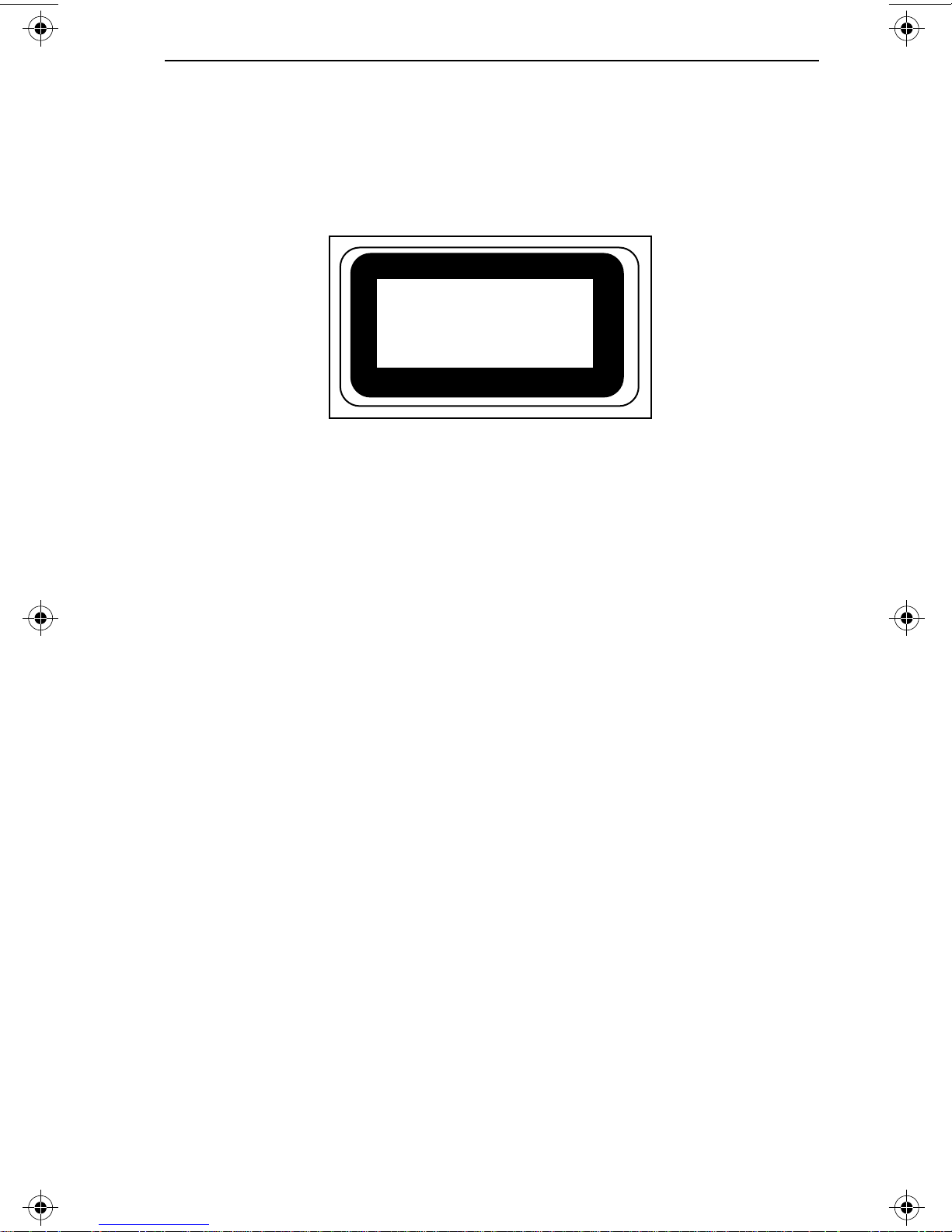
CLASS 1 LASER TRANSCEIVERS
The F6079 is a Class 1 Laser Product
CLASS 1
LASER PRODUCT
The F6079 adapter uses a Class 1 Laser transceiver.
Read the following safety information before
installing or operating the F6079 adapter.
The Class 1 laser transceivers use an optical feedback loop to
maintain Class 1 operation limits. This control loop eliminates the
need for maintenance checks or adjustments. The output is factory
set, and does not allow any user adjustment. Class 1 Laser
transceivers comply with the following safety standards:
• 21 CFR 1040.10 and 1040.11 U.S. Department of Health and
Human Services (FDA).
• IEC Publication 825 (International Electrotechnical
Commission).
• CENELEC EN 60825 (European Committee for
Electrotechnical Standardization).
When operating within their performance limitations, laser
transceiver output meets the Class 1 accessible emission limit of all
three standards. Class 1 levels of laser radiation are not considered
hazardous.
iii
Page 5

SAFETY INFORMATION
SAFETY INFORMATION
CLASS 1 LASER TRANSCEIVERS
Laser Radiation and Connectors
When the connector is in place, all laser radiation remains within
the fiber. The maximum amount of radiant power exiting the fiber
(under normal conditions) is -12.6dBm or 55x10 -6 watts.
Removing the optical connector from the transceiver allows laser
radiation to emit directly from the optical port. The maximum
radiance from the optical port (under worst case conditions) is 0.8
W cm-2 or 8x10 3 W m-2 sr-1.
Do not use optical instruments to view the laser output. The use
of optical instruments to view laser output increases eye hazard.
When viewing the output optical port, power must be removed
from the network adapter.
iv
Page 6

CABLETRON SYSTEMS, INC.
CABLETRON SYSTEMS, INC.
PROGRAM LICENSE AGREEMENT
IMPORTANT: Before utilizing this product, carefully read this license
agreement.
This document is an agreement between you, the end user, and Cabletron
Systems, Inc. ("Cabletron") that sets forth your rights and obligations with
respect to the Cabletron software program ("the Program") contained in
this package. The Program may be contained in firmware, chips, or other
media.
BY UTILIZING THE PRODUCT, YOU ARE AGREEING TO
BECOME BOUND BY THE TERMS OF THIS AGREEMENT,
WHICH INCLUDES THE LICENSE AND THE LIMITATION OF
WARRANTY AND DISCLAIMER OF LIABILITY. IF YOU DO
NOT AGREE TO THE TERMS OF THIS AGREEMENT,
PROMPTLY RETURN THE UNUSED PRODUCT TO THE PLACE
OF PURCHASE FOR A FULL REFUND.
CABLETRON SOFTW
1. LICENSE You have the right to use only the one (1) copy of the
Program provided in this package subject to the terms and conditions of
this License Agreement.
2. OTHER RESTRICTIONS You may not reverse engineer, decompile,
or disassemble the Program.
3. APPLICABLE LAW This License Agreement shall be interpreted and
governed under the laws and in the state and federal courts of New
Hampshire. You accept the personal jurisdiction and venue of the New
hampshire courts.
EXCLUSION OF WARRANTY AND DISCLAIMER OF LIABILITY
1. EXCLUSION OF WARRANTY Except as may be specifically provided
by Cabletron in writing, Cabletron makes no warranty, express or
implied, concerning the Program (including its documentation and
media).
ARE PROGRAM LICENSE
v
Page 7

PROGRAM LICENSE AGREEMENT
CABLETRON DISCLAIMS ALL WARRANTIES, OTHER THAN THOSE
SUPPLIED TO YOU BY CABLETRON IN WRITING, EITHER IMPRESS
OR IMPLIED, INCLUDING BUT NOT LIMITED TO IMPLIED
WARRANTIES OF MERCHANTABILITY AND FITNESS FOR A
PARTICULAR PURPOSE, WITH RESPECT TO THE PROGRAM, THE
ACCOMPANYING WRITTEN MATERIALS, AND ANY
ACCOMPANYING HARDWARE.
2. NO LIABILITY
FOR CONSEQUENTIAL DAMAGES. IN NO EVENT
SHALL CABLETRON OR ITS SUPPLIERS BE LIABLE FOR ANY
DAMAGES WHATSOEVER (INCLUDING, WITHOUT LIMITATION,
DAMAGES FOR LOSS OF BUSINESS, PROFITS, BUSINESS
INTERRUPTION, LOSS OF BUSINESS INFORMATION, SPECIAL,
INCIDENTAL, CONSEQUENTIAL, OR RELIANCE DAMAGES, OR
OTHER LOSS) ARISING OUT OF THE USE OR INABILITY TO USE
THIS CABLETRON PRODUCT, EVEN IF CABLETRON HAS BEEN
ADVISED OF THE POSSIBILITY OF SUCH DAMAGES. BECAUSE
SOME STATES DO NOT ALLOW THE EXCLUSION OR LIMITATION
OF LIABILITY FOR CONSEQUENTIAL OR INCIDENTAL DAMAGES,
OR IN THE DURATION OR LIMITATION OF IMPLIED WARRANTIES
IN SOME INSTANCES, THE ABOVE LIMITATIONS AND EXCLUSIONS
MAY NOT APPLY TO YOU.
UNITED ST
ATES GOVERNMENT RESTRICTED RIGHTS
The enclosed product (a) was developed solely at private expense; (b)
contains "restricted computer software" submitted with restricted rights
in accordance with section 52227-19 (a) through (d) of the Commercial
Computer Software - Restricted Rights Clause and its successors, and (c)
in all respects is proprietary data belonging to Cabletron and/or its
suppliers.
For Department of Defense units, the product is licensed with "Restricted
Rights" as defined in the DoD Supplement to the Federal Acquisition
Regulations, Section 52.227-7013 (c) (ii) and its successors, and use,
duplication, or disclosure by the government is subject to restrictions as
set forth in subparagraph (c) (1) (ii) of the Rights in Technical Data and
Computer Software clause at 252.227-7013. Cabletron Systems, Inc. 35
Industrial Way, Rochester, New Hampshire 03867.
vi
Page 8

CHAPTER 1
INTRODUCTION
INTRODUCTION
Welcome to the Cabletron Systems
Network Adapter Installation Guide.
F6019, F6059, F6069, and F6079
This manual is a simple
installation and reference guide for the Cabletron Systems FDDI ,
and FDDI Over Copper network adapters for NuBus compatible
computers. The FDDI network adapters connect your Macintosh to
a dual ring Fiber Distributed Data Interface type network
employing Multimode Fiber, Single Mode Fiber, or 100 megabit
FDDI Over Copper technologies.
You should read through this manual to gain a full understanding
of the capabilities of the Cabletron FDDI and FDDI Over Copper
network adapters for NuBus equipped Macintosh computers.
1.1 USING THIS MANUAL
This manual is structured so that you can follow sequential
chapters as you install and test the Cabletron network adapters.
Chapter 1,
Introduction
, discusses the capabilities of the Cabletron
network adapters.
Chapter 2,
Installing the Adapter
s, contains instructions for
installing the network adapters into a Macintosh that supports
NuBus.
Chapter 3,
Installing Network Software,
provides instructions for
installing network drivers and network management software.
Chapter 4,
Network Connections
, provides instructions for
connecting the adapters to the FDDI network.
Chapter 5,
Diagnostics
, explains how to use the diagnostic
program to verify that the network adapter is communicating
properly with the network and the computer interface.
Page 1 - 1
Page 9

INTRODUCTION
Appendix A,
A/UX Driver and Utilities
, shows how to install the
Cabletron A/UX® driver, and use A/UX statistics and edit utilities.
Appendix B,
FDDI Media Specifications
, lists the specifications
for Multimode Fiber, Single Mode Fiber, and FDDI Over Copper
twisted pair media.
1.2 GETTING HELP
If you need additional support related to the network adapters, or
if you have any questions, comments, or suggestions concerning
this manual, contact Cabletron Systems Technical Support. Before
calling Cabletron Technical Support, please have the following
information available for use by the Technical Support personnel:
• The network adapter type and serial number.
• The software version of the Cabletron software diskette.
• Your computer model (i.e., Macintosh Quadra XXX, IIci, etc.)
and operating system (i.e., System 7.1).
• The make and model of any other adapters in your system.
You can contact Cabletron Systems Technical Support by:
Phone: (603) 332-9400
FAX: (603) 335-4743
BBS: (603) 335-3358 (4 lines available)
To contact Cabletron Technical Support on the Internet, send email
to:
[email protected] ( IP address 134.141.197.25)
available for anonymous FTP download from
ctron.co
. Drivers are
m.
CompuServe subscribers can also contact Cabletron Technical
Support through the Cabletron Forum by entering:
at any ! prompt.
Page 1 - 2
GO CTRON
Page 10

INTRODUCTION
1.3 NETWORK ADAPTER FEATURES
This section outlines the features of the FDDI and FDDI Over
Copper network adapters. Table 1-1, below shows the FDDI
adapter models and media variations for NUBus equipped
computers.
Table 1-1. FDDI Adapter Models and Media Types
Adapter Model Media
F6019 Unshielded Twisted Pair
F6059 Shielded Twisted Pair
F6069 Multimode Fiber
F6079 Single Mode Fiber
1.3.1 F6019 Adapter Connectivity
The F6019 network adapter connects your NuBus compatible
Macintosh computer to an ANSI Standard unshielded copper
twisted pair Distributed Data Interface network. The F6019
network adapter uses industry standard RJ-45 twisted pair
connectors. The F6019 adapter can be configured as either a Single
Attach-, or Dual Attach station as described in the ANSI FDDI
Over Copper Standard. LANVIEW LEDs show the status of the
network link and on-board processor.
1.3.2 F6059 Adapter Connectivity
The F6059 network adapter connects your NuBus compatible
Macintosh computer to an ANSI Standard unshielded copper
twisted pair Distributed Data Interface network.
Page 1 - 3
Page 11

INTRODUCTION
The F6059 network adapter uses industry standard RJ-45 twisted
pair connectors. The F6059 adapter can be configured as either a
Single Attach-, or Dual Attach station as described in the ANSI
FDDI Over Copper Standard. LANVIEW LEDs show the status of
the network link and on-board processor.
1.3.3 F6069 Adapter Connectivity
The F6069 FDDI network adapter connects your NuBus
compatible Macintosh computer to an ANSI Standard X3T9.5
Multimode Fiber Distributed Data Interface network. The F6069
FDDI network adapters use industry standard Type S dual fiber
Multimode FDDI connectors. The F6069 adapter can be configured
as either a Single Attach, or Dual Attach station as described in the
ANSI X3T9.5 Standard. LANVIEW LEDs show the status of the
FDDI Link and on-board processor.
1.3.4 F6079 Adapter Connectivity
The F6079 Single Mode FDDI network adapter connects your
NuBus compatible Macintosh computer to an ANSI Standard
X3T9.5 Single Mode Fiber Distributed Data Interface network. The
F6079 FDDI network adapters use industry standard Type S dual
fiber Single Mode FDDI connectors. The F6079 adapter can be
configured as either a Single Attach, or Dual Attach station as
described in the ANSI X3T9.5 Standard. LANVIEW LEDs show the
status of the FDDI Link and on-board processor.
1.4 SOFTWARE
Software drivers are supplied by Cabletron on a floppy diskette
supplied with the network adapter. The drivers support industry
standard ANSI X3T9.5 FDDI Protocol, Apple’s FDDITalk Interface,
and Apple’s A/UX operating system.
Page 1 - 4
Page 12

INTRODUCTION
1.5 STATISTICS
Statistics can be gathered for the F60XX network adapter models
either from your Macintosh, or from another workstation utilizing
®
Cabletron Systems’
Remote LANVIEW
LANVIEW for SunNet Manager
®
, or
/Windows, Remote
SPECTRUM®. Through this
software, you can gather statistics on the adapter’s activity on the
network. For further information on gathering network adapter
statistics from another workstation, refer to the appropriate
network management manual.
The network adapter’s A/UX driver software also includes a
statistics utility. See Appendix A,
A/UX Driver and Utilities
.
1.6 LANVIEW® LEDs
The F60XX series of network adapters incorporate Cabletron’s
LANVIEW
®
LEDs. The LEDs help you diagnose problems, such as
a failure to establish a link between the adapter and an active
device at the other end of the network link. Individual LEDs are
provided to advise you when the adapter is connected correctly to
the network link, and when an on-board processor error occurs on
the network adapter.
1.7 TECHNICAL SPECIFICATIONS - F60XX Models
• System Interface Fully compatible with 32-bit NuBus,
all Macintosh and Quadra
computers that support NuBus and
NuBusII architectures.
• FDDI hardware Motorola FDDI Chipset.
• Data Transfer 32-bit Bus Master, implementing two
• Buffer Memory 1 Megabyte.
clock data transfer whenever
possible.
Page 1 - 5
Page 13

INTRODUCTION
• LED Indicators Processor LED (Red) - Flash rate
indicates processor status
1 flash/sec for 30 secs(Heartbeat - OK)
Continuous - Adapter Failure
Transmit (Green) FDDI output
Receive (Yellow) FDDI input
Link Status (Bicolor LED)
Red - No Connection
Green - Link Valid
Unlit - Signal Detect, No Link
• Diagnostics Power-on diagnostics provide
functional test of adapter hardware
at power up. Status reported by
LEDs described above.
• Station Management Stored in on-board RAM.
(Downloaded when network driver
loads.)
• Processor Motorola 68ec020 low power CPU.
• Cable Length F6019 F6019, unshielded twisted pair
FDDI Over Copper cable - supports
up to 100 meters between stations
using Category 5 unshielded
twisted pair cable.
• Cable Length F6059 F6059, shielded twisted pair FDDI
Over Copper cable - supports up to
100 meters between stations using
Type 1, individually and overall
shielded, 150 ohm cable.
Page 1 - 6
Page 14

INTRODUCTION
• Cable Length-F6069 F6069, Multimode Cable -supports
up to 2km (1.2 miles) between
stations using 62.5/125 um graded
index fiber cable.
• Cable Length-F6079 F6079, Single Mode FDDI Cablesupports up to 40 km (24 miles)
between stations using 8.7 /125 um
Single Mode Fiber Cable.
• Netwk Interface F6019, F6059 - Industry standard
RJ-45 connectors. F6069, F6079 Industry standard S type fiber optic
connectors.
1.8 TECHNOLOGY OVERVIEW
1.8.1 100 Megabit/Second FDDI Over Copper
The migration of FDDI fiber optic technology to twisted pair
copper wire began with the desire to utilize inexpensive, and
previously installed twisted pair cable as a replacement for more
expensive vendor-specific media.
There are many benefits to be gained from operating FDDI
technology on twisted pair cable; increased bandwidth,
elimination of rewiring costs, reduced cost of new installations,
and simpler, and less expensive transceivers.
In pursuit of these goals, Cabletron Systems is participating in the
standards process with the American National Standards Institute
(ANSI), creating a draft standard for the transmission of 100 Mb/s
FDDI data over twisted pair copper wire. The new standards,
Twisted Pair - Physical Media Dependent (
Twisted Pair - Physical Media Dependent (
TP-PMD
STP-PMD
) and Shielded
) define the
minimum performance requirements for both shielded and
unshielded twisted pair cable.
Page 1 - 7
Page 15

INTRODUCTION
The guidelines for the new standard are set forth below:
• Transmit distance of 100 meters for both UTP and STP cable.
• The same Bit Error Rate as FDDI over fiber cable (2 x 10⁻¹).
• FCC Class A (commercial) certification.
• European EN55022 Class A (commercial) certification.
• UTP - Category 5 cable (as specified in EIA/TIA TSB-36).
• STP - Type 1, individually and overall shielded, 150 ohm cable.
Some vendors are manufacturing STP-only products based on an
earlier proposal rejected by ANSI (the “Green Book Proposal”).
These products are proprietary and non-standard, and ANSI does
not recognize or support them.
The ANSI EIA/TIA 586 document was completed in 1991 and laid
the foundation for cable plants supporting data rates of 100
Megabits per second. This document specifies that MultiMode
fiber be installed for vertical riser applications and horizontal
distances greater than 100 meters.
Category 5 UTP cable is specified for desktop wiring distances up
to 100 meters and data rates up to 100 Mb/s. Two Technical System
Bulletins (TSB) were issued by EIA/TIA after ANSI EIA/TIA 586.
TSB-36 classifies UTP cables into categories 3, 4, and 5, and
provides characteristic and performance values at particular data
rates. TS8-40 classifies connector hardware (punch-down blocks,
patch panels, wall jacks, etc.) into categories 3, 4, and 5, and also
provides characteristic and performance values at particular data
rates.
Anyone considering installing a new cable plant should consult all
three documents. They are available through your local EIA
publications office - call (202) 457-4963.
Page 1 - 8
Page 16

INSTALLING THE AD APTERS
CHAPTER 2
INSTALLING THE ADAPTERS
This chapter contains instructions for preparing and installing
your Cabletron Systems’ F60XX series network adapter into your
Macintosh computer. The F60XX series adapters are compatible
with any Macintosh that supports NuBus. The Cabletron F60XX
series adapters are software configurable; they have no jumpers or
switches.
Software installation procedures including network drivers and
management, are described in Chapter 3,
Software
. Chapter 4,
Network Connections
for connecting the adapters to a network segment.
Installing Network
, provides instruction
2.1 HARDWARE REQUIREMENTS
Your Macintosh must have a NuBus slot in order to use any of the
F60XX series network adapters. The Macintosh IIsi requires an
Apple math coprocessor/NuBus adapter board to interface the
adapter to the NuBus. Because of the single slot limitation, the
Macintosh IIsi can be configured as a Single Attach Station only.
Consult the “Setting Up Your Macintosh” booklet that came with
your computer for machine-specific installation information.
2.2 UNPACKING THE ADAPTERS
The complete installation package should contain one box with a
network adapter and this manual, and a shrink-wrapped package
which contains the software diskette and the license agreement. To
unpack the card and the software, carefully remove the adapter
from the box. Leave the adapter in the conductive pouch until you
are ready to install it. Do not open the shrink-wrapped package
until you are ready to install the software. Be sure to read the
licensing agreement included in the shrink-wrapped package.
Page 2 - 1
Page 17
INSTALLING THE AD APTERS
2.3 PREPARING THE ADAPTER
The F60XX series adapters do not have any jumpers or switches.
Each adapter contains its own configuration ROM chip that sets
the card’s parameters for communication between the Macintosh
and the FDDI network.
Carefully remove the adapter (and daughter board, if a Dual
Attach configuration) from the protective pouches, and visually
inspect them.
The network adapters are sensitive to static discharges.
Hold the adapter by the top of the metal bracket and the
!
CAUTION:
opposite top corner. Avoid contact with the Macintosh bus
edge connector or any of the adapter’s components. Failure
to observe all static discharge precautions could result in
damage to the adapter.
NuBUS
Connector
Ribbon Cable Connectors
to dual attach daughter board
Processor
(red)
Receive
(yellow)
RJ-45 Connector
F6019/F6059
FDDI Cable
Insertion Key
LANVIEW
LEDs
Transmit Data
(green)
Bicolor LED
No Connection - (red)
Signal Detect - (off)
Link - (green)
FDDI
Connector
F6069/F6079
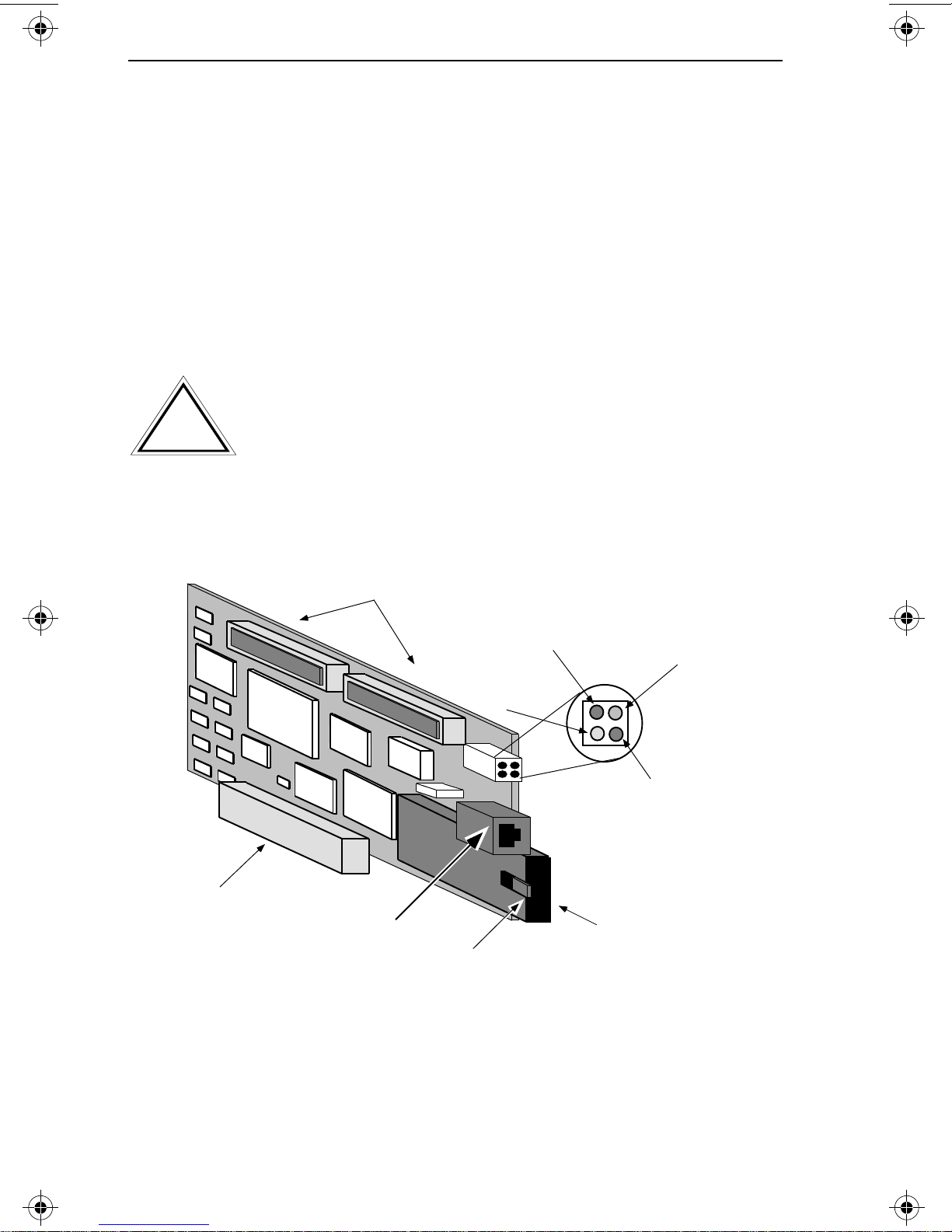
Figure 2-1. Nomenclature, F60XX FDDI Network Adapters
Page 2 - 2
Page 18

INSTALLING THE AD APTERS
2.4 LANVIEW LEDS
The F60XX series network adapters for the Macintosh incorporate
Cabletron Systems’ built-in visual diagnostic and status
monitoring LEDs called LANVIEW. The LANVIEW LEDs (shown
in Figure 2-1) are more effective than a network monitor, because
network troubleshooting personnel can quickly scan the LEDs to
diagnose network problems and determine which node or
segment is faulty. The F60XX series adapters employ four
LANVIEW LEDs. The functions of these LEDs are explained in the
following section.
2.4.1 Using LANVIEW LEDs
Processor LED (red)
The F60XX series adapters use an on-board Motorola 68ec020 CPU.
The Processor LED indicates the following conditions:
• When the Processor LED flashes at a rate of one flash per
second (the “heartbeat”) it indicates that the processor is
functioning normally.
The heartbeat is not a continuous signal - the one
NOTE
flash-per-second indication will only be displayed for
thirty seconds after power up.
• When the red Processor LED is illuminated in a steady state, it
indicates adapter failure.
To correct the problem, try restarting the Macintosh. (This will
reload the network driver, which will in turn, reload the SMT
management microcode).
Run the Cabletron diagnostics program successfully to ensure that
there is no “hard” problem with the adapter. If the steady state red
Processor LED indication persists, contact Cabletron Technical
Support.
Page 2 - 3
Page 19

INSTALLING THE AD APTERS
Receive (yellow)
The Receive LED illuminates to indicate that FDDI packets are
being received from the network.
Transmit Data (green)
The Transmit Data LED illuminates when FDDI packets are being
transmitted by the adapter onto the network.
Bicolor LED
This LED indicates one of three possible FDDI network link
conditions.
• Illuminates in red to indicate No Connection to the network.
Check all connections to the network link. See that Transmit
LED is illuminated.
• Remains unlit to indicate Signal Detect (a signal is being
received from the network, but the adapter is unable to
establish a link with another FDDI network device).
• Illuminates in green to indicate that Link has been established
with another FDDI device in the network.
If you are unable to establish a link with the FDDI
NOTE
network, try connecting this cable segment to a
working station. Run the diagnostic Loopback test
with a loopback connector to check the adapter.
2.5 INSTALLING THE ADAPTERS
Insert the adapter into an available NuBus slot. Refer to the
“Setting Up Your Macintosh” booklet that came with your
computer for more information on installing NuBus adapters.
Page 2 - 4
Page 20

INSTALLING NETWORK SOFTWARE
CHAPTER 3
INSTALLING NETWORK SOFTWARE
This chapter contains instructions for installing the FDDITalk,
network management, and statistic software for your Macintosh.
The network software operates with both Macintosh System
6.04and later, and System 7.XX.
SOFTWARE DISCLAIMER
Cabletron has tested its software with current virus checking
technologies. However, because no antivirus system is 100%
reliable, we strongly caution you to write protect and then verify
that the Licensed Software, prior to installing it, is virus-free with
an anti-virus system in which you have confidence. Cabletron
Systems makes no representations or warranties to the effect that
the Licensed Software is virus-free.
3.1 BACKING UP YOUR SOFTWARE DISK
The adapter software is provided on a 3.5 inch disk. Be sure to read
the License Agreement included in the shrink-wrapped package.
Check the labeling on the disk to be sure you have the proper
software to run on your system. We recommend that you make a
backup copy of the software prior to using it. Follow the
procedures in your System Software User’s Manual to make a
copy of your Cabletron software disk.
Page 3 - 1
Page 21

INSTALLING NETWORK SOFTWARE
3.2 INSTALLING FDDITALK AND STATISTICS
Your Macintosh must have System File Version 6.0.4 or later,
NOTE:
or System 7 to be able to run FDDITalk with the FDDI
adapters.
Apple’s AppleTalk, FDDITalk, and Cabletron Systems network
drivers for the FDDI adapters are provided on Cabletron’s Installer
Disk. Cabletron Systems’ Local Statistics program is automatically
installed during the basic installation procedure.
The Customize function of the Installer program allows you to
install SNMP Management and the interface for MacTCP. SNMP
Management allows network management packages to gather
statistics from the FDDI adapters on an SNMP-compliant network.
Any SNMP-compliant management software can gather the
statistics.
The MacTCP interface lets you run applications that require
MacTCP, such as NSCA TelNET 2.5, used to communicate with
UNIX hosts. See Sections 3.5, and 3.6, in this chapter, for more
information on using local statistics and MacTCP.
The FDDI adapter software can be loaded onto either the hard
drive or a 3.5 inch startup disk, depending on which you use as a
Startup Device. Refer to the Readme file on the software disk for
changes to the software that may not be reflected in this manual.
3.2.1 Installing FDDITalk onto Your Hard Drive
This procedure installs FDDITalk onto your hard drive. You can
also install Network Management or the MacTCP interface using
the Customize feature of the installer. To install FDDITalk onto
your hard drive:
• Insert your backup copy of the software disk into your disk
drive. You do not have to boot off the disk to use this installer.
Page 3 - 2
Page 22

INSTALLING NETWORK SOFTWARE
• Double click on the disk icon to open it. Double click on the
Installer icon to open the installation program. The logo screen
should appear.
• Click OK in the logo screen to bring you to the Installer screen.
• When the Installer screen appears, be sure that the proper
destination drive is selected. The hard drive should be selected
by default. If it is not selected, click on the Switch Disk button
to select the hard drive.
• Click on Easy Install. The Installer program automatically
selects the proper system version for your Macintosh, System 6
or System 7, and FDDITalk.
• The system must be rebooted after this installation.
Customizing must be done after rebooting from Easy Install. To
use the Customize window, click on the Customize button. The
Custom Install window will appear with installation options.
Select the optional SNMP management and/or the MacTCP
interface if you would like to install either.
• Click on the Install button. When installation is complete, a
message will appear saying your Macintosh must be restarted.
• Click on the Restart button, and your Macintosh will
automatically restart.
After your Macintosh has restarted, the FDDITalk icon should be
present in the Network option in the Control Panel.
Page 3 - 3
Page 23

INSTALLING NETWORK SOFTWARE
3.3 USING NETWORK MANAGEMENT
Your Macintosh must have System File Version 6.0.4 or later
NOTE:
and AppleTalk must be installed to be able to run the Network
Management software.
Management software is provided with all network adapters for
the Macintosh. The management for the Macintosh is an Init/cdev
file that is installed into your System Folder by the Customize
feature of the software installer program. Management is
automatically installed when the system is started. However, you
can turn management off if you want to.
You should have installed Network Management during the
installation procedures for FDDITalk. If it is not installed, refer to
the Customize Installation procedures in Section 3.2.1.
Management can be used by any workstation running an SNMPcompliant network management package. A network management
program reads the information in the management configuration
window. Before using network management with your adapter,
the software must be configured by entering information in certain
fields in the management configuration window.
To configure the network management, open the Control Panel
from your Desk Accessories. Select the FDDI SNMP Management
icon in the Control Panel.
The management configuration window contains the following
fields. Enter the appropriate information in the designated fields.
Note that some fields are not user-accessible.
• CName - This is a user-configurable field of up to 32
characters. The default is public, and is listed to
authenticate the SNMP request from the Macintosh.
• Location - Enter the location, up to 32 characters, of the
Macintosh.
Page 3 - 4
Page 24

INSTALLING NETWORK SOFTWARE
• Owner - This field, up to 32 characters, displays the name
entered in the User Name field in the Chooser.
• Comment - Enter a field, up to 32 characters, containing
miscellaneous information.
• MMAC addr = xx-xx-xx-xx-xx-xx - Enter the address for the
MMAC to which the adapter is connected.
• MMAC Port = xx - Enter the number of the port on the
MMAC board to which the adapter is connected. These are
two-digit values, i.e., 01, 10, etc.
• MMAC Board = xx - Enter the number of the MMAC board
to which the adapter is connected. These are two-digit
values, i.e., 01, 02, etc.
• IP = x.x.x.x - Enter the Internet Protocol address for the
Macintosh in which the adapter is installed. In this address,
x is a one to three digit decimal number. This information
will appear in the PC Card Statistics Screen of Remote
LANVIEW/Windows.
Click Save in the management window. Close out of the Control
Panel and restart your Macintosh.
Each time your Macintosh is started, the management will be
automatically turned on. The management icon (View A, Fig. 3-3)
will appear on the startup screen. To turn management off:
• Hold the mouse button down as the Macintosh starts up. A
is placed over the management icon (View B).
• To turn management back on, simply Restart your Macintosh.
If a is placed over your management icon when you start up:
• Check that FDDITalk is selected in the Network option of your
Control Panel.
• Restart your Macintosh without pressing the mouse button.
Page 3 - 5
Page 25
INSTALLING NETWORK SOFTWARE
3.4 ACTIVATING FDDITALK
After FDDITalk has been installed, it must be activated so your
Macintosh can communicate on the FDDI network. FDDITalk is
activated through the Network option in the Control Panel
(see Fig. 3-4). This option was placed in the Control Panel when
you ran the Installer program to load FDDITalk.
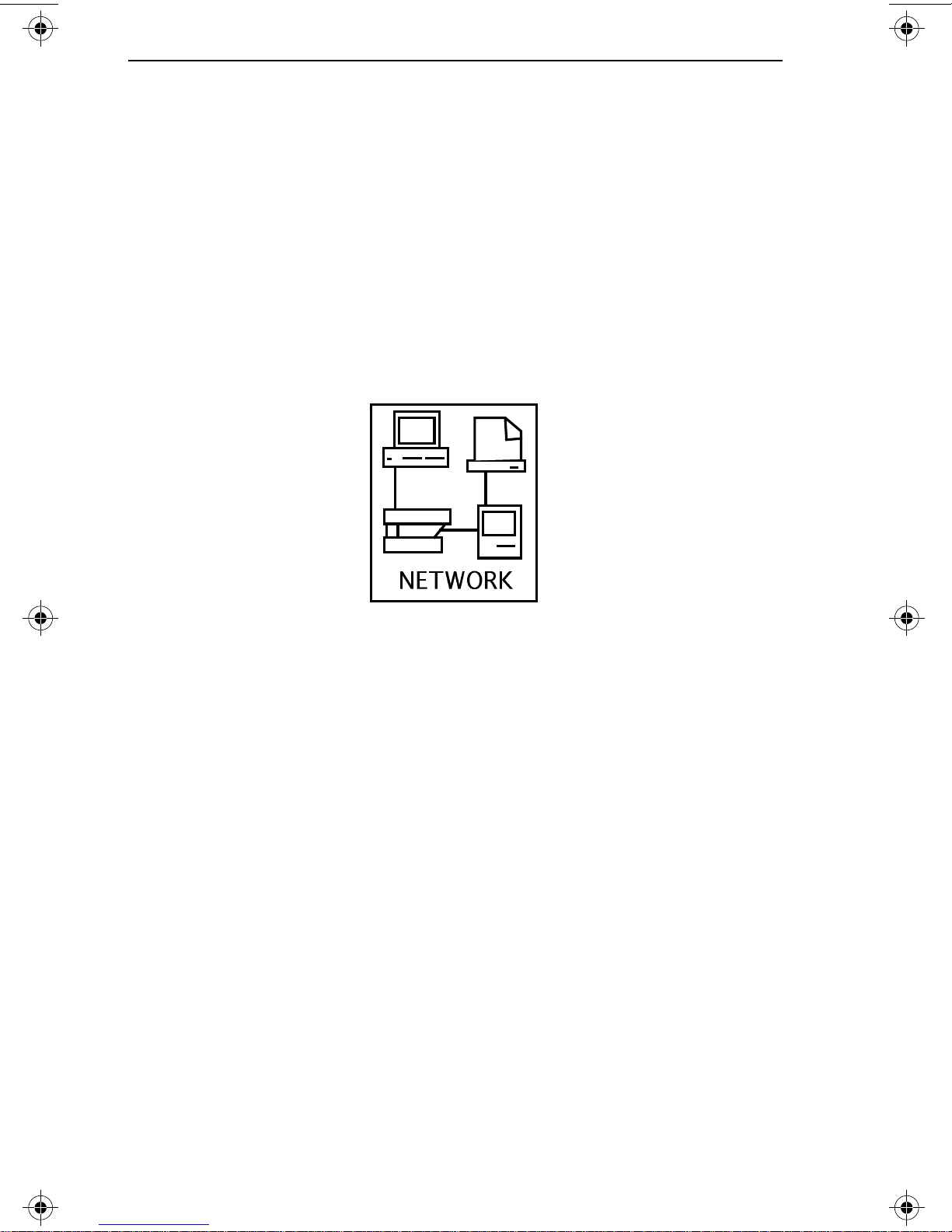
Icons will appear when you are in the Network option window FDDITalk, Built-In, and possibly others. Selecting the FDDITalk
icon activates FDDITalk and allows your Macintosh to
communicate on the FDDI network.
Figure 3-1. Network Icon
3.5 LOCAL STATISTICS
The FDDITalk installer will automatically install a local statistics
application that is accessible from the Apple menu. Local stats are
only available if the FDDI driver is loaded.
If the FDDITalk icon is selected from the control panel or from
MacTCP, information about the number of frames and bytes sent
and received is displayed as well as the SMT revision, driver
revision, and adapter address.
Page 3 - 6
Page 26

INSTALLING NETWORK SOFTWARE
3.6 MacTCP
If you wish to run MacTCP over FDDI, select Interface for FDDI
MacTCP from the Customize function. Then select LAPFDDI in
the MacTCP control panel. Note that MacTCP is not included on
the installer disk and is available from Apple.
Page 3 - 7
Page 27

NETWORK CONNECTIONS
CHAPTER 4
NETWORK CONNECTIONS
If you are not familiar with the characteristics of FDDI networks,
you should review the hardware, network, and environmental
requirements outlined in the ANSI X3T9.5 FDDI Network
Specification. All conditions, guidelines, specifications and
requirements included in the ANSI X3T9.5 specification must be
met to ensure satisfactory performance of the FDDI adapter.
Failure to follow these guidelines could also result in
unsatisfactory network performance.
4.1 OPTICAL FIBER CONNECTIONS
The F60XX adapters can be configured as a Single Attach Station
(SAS), or a Dual Attach Station (DAS), as defined in the ANSI
X3T9.5 specification. Dual Attach Station configuration is
implemented by the use of a “daughter” board. Instructions for
installing the daughter board are provided in this chapter.
The FDDI adapter connects to the FDDI ring via a type S FDDI
connector located on the rear-facing bracket of the adapter.
Remove the protective cover from the duplex shroud end of the
FDDI cable segment. If the fibers need to be cleaned, use a fiber
optic cleaning kit.
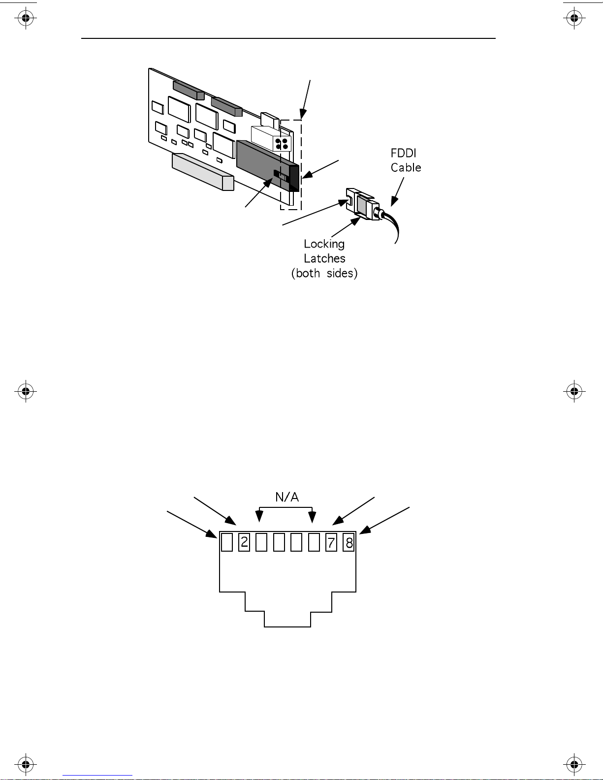
To connect the adapter to an optical fiber FDDI network segment,
insert the duplex connector into the FDDI cable receptacle at the
back of the adapter. Observe the slotted key in the center of the
receptacle, and the matching key on the duplex connector (see
Figure 3-1). Slide the duplex shroud into the receptacle until the
latches on the sides of the shroud click into place.
Page 4 - 1
Page 28
NETWORK CONNECTIONS
FDDI Cable
Insertion Key
Figure 4-1. Connecting a Fiber Optic Cable
Bracket
FDDI
Connector
4.1.1 Twisted Pair FDDI Connections
The RJ-45 pinout configuration for Unshielded Twisted Pair (UTP)
and Shielded Twisted Pair (STP) Physical Layer Medium
Dependent (PMD) ports is shown below.
Transmit -
Transmit +
1
Receive +
Receive -
Figure 4-2. RJ-45 TP-PMD Port Pinouts
Page 4 - 2
Page 29

NETWORK CONNECTIONS
When connecting two twisted pair ports together (e.g., an M
NOTE
type port on an FDCMIM-24 to an F6069 FDDI network
adapter), a transmit and receive cross-over must occur
between the two devices (i.e., within the cable).
4.2 Checking Network Connections
Observe the condition of the LANVIEW LEDs on the FDDI
adapter rear bracket before and after connecting the adapter to the
FDDI network.
The Bicolor LED should illuminate green after the adapter is
connected to the FDDI network, indicating that a link has been
established between the adapter and another device on the FDDI
network.
If the Bicolor LED does not illuminate, it indicates that an FDDI
signal is being received but Link has not been established. If the
bicolor LED illuminates in red, there is NO Connection to the
FDDI network.
If you cannot establish a link to the FDDI network, recheck your
FDDI cable connections, and observe the red Processor LED on the
adapter. If this LED is illuminated continuously, there is a
processor failure. Reload the network driver which will
automatically download the SMT management microcode. If this
condition persists, call Cabletron Technical Support.
4.2.1 Network Requirements/Specifications
When connecting segments to the adapter, the network
requirements outlined in the ANSI X3T9.5 specification must be
met. Failure to follow these guidelines can result in degradation of
network performance.
Page 4 - 3
Page 30
NETWORK CONNECTIONS
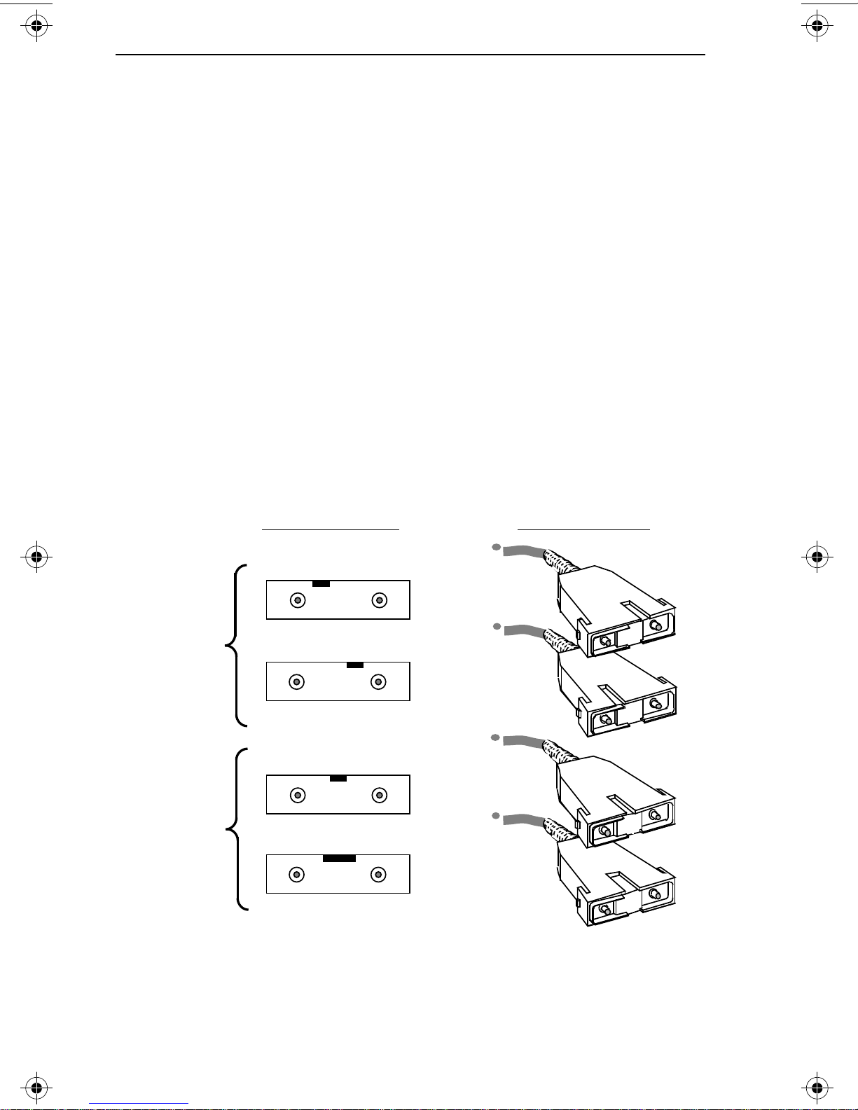
4.2.2 FDDI Station Configurations
The following terminology is explained in more detail in ANSI
X3T9.5. There are four valid FDDI station configurations:
• SAS - Single Attach Station
• DAS - Dual Attach Station
• DAC - Dual Attach Concentrator
• SAC - Single Attach Concentrator
FDDI devices are physically attached to the ring using fixed
shroud duplex (FSD) media interface connectors. Four connectors
are defined in the X3T9.5 FDDI Standard Physical Layer, (the PMD,
Physical Media Dependent, standard). They provide proper
alignment of the trunk fibers for each of the valid configurations.
DUAL
ATTACHMENT
SINGLE
ATTACHMENT
FDDI RECEPTACLES
SECONDARY OUTPRIMARY IN
TYPE A
SECONDARY IN
TYPE B
IN OUT
TYPE M
IN OUT
TYPE S
PRIMARY OUT
FDDI CONNECTORS
Type A
Type B
Type M
Type S
Figure 4-3. FDDI Connector Types
Page 4 - 4
Page 31
NETWORK CONNECTIONS
Types A, B, and M are precision connectors, mechanically keyed to
assure proper connections to Primary-In and Primary-Out fibers.
Types A and B provide dual attachment to the primary and
secondary data paths of the main ring. Type M is used for single
attachment stations, at the workstation end of the SAS lobe.
The type S connector has a wide, centrally located keyway and is
considered a non-precision connector for use at the station end of
an SAS lobe cable. Figure 3-3, FDDI Connector Types, shows the
configurations of the four types of media interface connectors. For
a more detailed description of FDDI network characteristics and
configurations, please read the ANSI X3T9.5 specification.
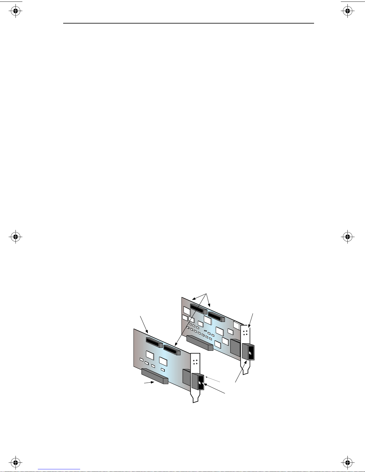
4.3 IMPLEMENTING A DUAL ATTACH STATION
The Dual Attach Station configuration is implemented by
installing a “daughter board.” The daughter board plugs into a slot
adjacent to the F60XX FDDI adapter and connects to the FDDI
adapter by a pair of ribbon cables. The daughter board provides
the additional FDDI connectors and ancillary circuitry for Dual
Attach Station operation. The daughter board obtains its power
from the bus slot it is plugged into. Figures 3-4 and 3-5, provide
instructions for installing the daughter board and connecting the
daughter board to the FDDI adapter.
Connectors for
Daughter Board Cables
Daughter
Board
LANVIEW
LEDs
Figure 4-4. Installing a Daughter Board
NuBUS
Connector
FDDI
Connectors
FDDI Cable
Insertion Key
Page 4 - 5
Page 32

NETWORK CONNECTIONS
4.3.1 Installing a Daughter Board
To install a daughter board, follow the instructions outlined below:
• Turn off the power to the computer and peripherals, and
disconnect all power cords and cables.
• Remove the computer cover and select a slot for the daughter
board, adjacent to the slot occupied by the FDDI adapter. We
recommend the slot immediately to the left of the FDDI
adapter as viewed from the rear (bracket) of the adapter.
• If you have not done so, remove the daughter board from its
protective pouch, and visually inspect it.
• Refer to the installation procedures for NuBus adapters in the
hardware manual for your Macintosh. Install the daughter
board as you would the FDDI adapter, in a slot adjacent to the
FDDI adapter.
• Connect the daughter board to the FDDI adapter. Plug the
interconnecting ribbon cables into the FDDI adapter and
daughter board connectors . Observe the polarized keying of
the cable and connectors.
• Replace the computer cover, reconnect all cables and power up
the computer.
• Connect the FDDI cables to adapter and daughter board
according to the FDDI ring configuration. Consult the ANSI
X3T9.5 specification for a description of Dual Attach Station
FDDI ring topology.
• After connecting the adapter and daughter board to the FDDI
ring, observe the LANVIEW LEDs (see Section 2.5) to
determine the status of the adapter and the FDDI ring.
Page 4 - 6
Page 33

DIAGNOSTICS
CHAPTER 5
DIAGNOSTICS
The F60XX adapter diagnostics program verifies that the adapter
you installed is communicating properly with your Macintosh and
the FDDI network. The diagnostics program checks the adapter’s
central processor, memory, and network interface controller.
Included is a loopback test that verifies both the transmit and
receive functions of the FDDI network interface.
5.1 LOADING DIAGNOSTICS ONTO THE HARD DRIVE
You can run the diagnostics program from a disk or hard drive. If
you wish to run the diagnostics program from the hard drive,
insert a copy of the Cabletron software disk in your disk drive and
open the Cabletron Software disk icon. Drag the Diags folder onto
your hard drive and close the Cabletron software disk icon.
When using the diagnostics program, be sure you have selected
Built-In from the Network options in your Control Panel to
disable the F60XX adapter network port. After selecting Built-In,
restart your Macintosh. The diagnostic tests cannot run if the
Macintosh is receiving traffic from the network.
You must reselect the network port and restart the Macintosh
NOTE:
after using the diagnostics.
Be sure to disconnect the FDDI network cable attached to the
adapter. Also, If you are operating under System 7, or in
MultiFinder™ under System 6, you will not be able to access other
applications while you are accessing the diagnostics.
Page 5 - 1
Page 34

DIAGNOSTICS
5.2 ACCESSING THE DIAGNOSTICS
If you boot up your Macintosh from a disk with FDDITalk
installed, be sure the Built-In port is selected on the Network
Control Panel to disable the adapter’s FDDI network port.
To access the diagnostics, open the FDDI_Diags folder. Then
double click on the FDDI_Diags icon to start the diagnostics.
A window will appear in the center of your monitor’s screen. Just
below the window’s title bar will be the “Boot Version (where
applicable),” “SMT Version,” and the adapter’s “Network ID.”
If for any reason a NOT AVAILABLE message appears after
NOTE:
the above three lines during test, the adapter’s processor is
unavailable for communication with the host computer. Click
on EXIT in the lower corner of the window. If the device driver
for the F60XX host system is active, disable the device driver
by opening the Network control panel and clicking on Built-
In. Always make sure to restart the host system after changing
to Built-In, to properly disable the device driver.
5.3 THE DIAGNOSTIC TEST MENU
To the left of the diagnostics application window is the Diagnostic
Test Menu selection box. This box contains the available adapter
tests. Each test in the Diagnostic Test Menu selection box has an
associated check box. When the diagnostics application window
opens, all check boxes accompanying tests except Ext Loopback
and Memory Test will be checked.
External Loopback test requires that a loopback plug be
NOTE:
attached to the FDDI connector on the adapter. Otherwise,
errors will result.
Page 5 - 2
Page 35

DIAGNOSTICS
5.3.1 Diagnostic Slot Menu
To the right of the Diagnostic Test Menu is the Diagnostic Slot
Menu. All NuBus slots containing FDDI adapters will appear in
the Diagnostic Slot Menu with enabled check boxes. To exclude a
slot from the diagnostic testing, click on the appropriate check box
to remove the check mark.
When you are satisfied with the configuration of the Diagnostic
Menus, click the START button to the right of the application
window to start testing. Testing can be terminated at any time by
clicking on the STOP button.
There may be some delay after the STOP button is clicked on
NOTE:
by the mouse before the tests are actually stopped - this
depends on the type of test currently running.
5.3.2 Running The Diagnostic Tests
If the Pass Total text editable box is empty or contains a zero, the
diagnostics program will cycle through all enabled tests for all
NuBus slots with adapters in them. This will continue indefinitely,
regardless of any errors encountered, until the Stop button is
clicked.
If a number other than zero is entered into the Pass Total text
editable box, the diagnostics program will run until an error is
detected, or the desired number of test passes is completed. The
Pass Count box displays the current number of test passes
completed by the diagnostic program.
If the diagnostic detects an error, the program will not advance
NOTE:
to the next test in the series of tests for the slot under test.
Page 5 - 3
Page 36

DIAGNOSTICS
5.3.3 Test Messages
As each slot is tested, a TESTING message is displayed to the right
of the slot heading in the Diagnostic Slot Menu. Upon completion
of each test for a given slot, a PASSED or FAILED message will be
displayed to the right of the slot’s heading in the Diagnostic Slot
Menu.
As each test is run, the check box changes to a check mark to
indicate that the test is running. Comments about the test and
Status Messages are displayed in the comment box at the bottom of
the application window. Once the battery of tests is completed for
a given NuBus slot, the diagnostic program advances to the next
NuBus slot selected, and the test sequence begins again.
5.3.4 FDDI Results File
Every time you exit the diagnostics application, a file named fddi
results is generated and stored in the folder where the diagnostic
application resides. This file contains the results for all tested
NuBus slots, the Network ID address, the SMT and Boot Code
version, the total passes and errors for each slot, and a Status
message for each slot.
Reselect the Network Port in the Network Control panel and
NOTE:
restart your system after running the diagnostics.
If you encounter any problems, call Cabletron Systems Technical
Support. See Getting Help, in Chapter 1.
Page 5 - 4
 Loading...