

Page 1

ETWMIM
ETHERNET / TOKEN RING / WAN
MEDIA INTERFACE MODULE
USER’S GUIDE
CABLETRON SYSTEMS, P. O. Box 5005, Rochester, NH 03867-0505
Page 2

NOTICE
Cabletron Systems reserves the right to make changes in specifications and other
information contained in this document without prior notice. The reader should in all
cases consult Cabletron Systems to determine whether any such changes have been
made.
The hardware, firmware, or software described in this manual is subject to change
without notice.
IN NO EVENT SHALL CABLETRON SYSTEMS BE LIABLE FOR ANY INCIDENTAL,
INDIRECT, SPECIAL, OR CONSEQUENTIAL DAMAGES WHATSOEVER
(INCLUDING BUT NOT LIMITED TO LOST PROFITS) ARISING OUT OF OR
RELATED TO THIS MANUAL OR THE INFORMATION CONTAINED IN IT, EVEN
IF CABLETRON SYSTEMS HAS BEEN ADVISED OF, KNOWN, OR SHOULD HAVE
KNOWN, THE POSSIBILITY OF SUCH DAMAGES.
CAUTION: THIS T1 CARD IS INTENDED TO BE INSTALLED IN CSA CERTIFIED/
UL LISTED EQUIPMENT BY A QUALIFIED SERVICE PERSON. CHECK THE
EQUIPMENT OPERATION/INSTALLATION INSTRUCTIONS AND/OR
EQUIPMENT MANUFACTURER TO VERIFY/CONFIRM YOUR EQUIPMENT IS
SUITABLE FOR INSTALLED APPLICATION CARDS.
CAUTION: ALWAYS DISCONNECT T1 BOARD (THE ONE WITH THE TELEPHONE
PLUG/JACK) FROM THE TELEPHONE SYSTEM WHEN INSTALLING OR WHEN
THE COVERS ARE REMOVED FROM THE HOST PRODUCT.
CAUTION: APPLY THE ENCLOSED ADHESIVE WARNING LABEL TO THE
OUTSIDE OR INSIDE OF THE EQUIPMENT ENCLOSURE ADJACENT TO THE T1
CARD.
© Copyright August 1994 by:
Cabletron Systems Inc.
P.O. Box 5005, Rochester, NH 03867-0505
All Rights Reserved
Printed in the United States of America
Order Number: 9030661-01 August, 1994
ETWMIM, MMAC, T1-SRM, EPIM-T, EPIM-X, EPIM-F1/F2, EPIM-F3, EPIM-C
TPT-T, FOT-F, FOT-F3
Systems, Inc.
Spectrum
IBM
VT200
Compuserve
Ethernet
, and
LANVIEW
is aregistered trademark of International Business Machines Corporation.
and
VT300
is a registered trademark of Compuserve, Inc.
is a trademark of Xerox Corporation.
, and
Flexible Network Bus
are registered trademarks of Cabletron Systems, Inc.
are trademarks of Digital Equipment Corporation.
are trademarks of Cabletron
,
Printed on recycled paper
i
Page 3

NOTICE
FCC NOTICE
This device complies with Part 15 of the FCC rules. Operation is subject to the following
two conditions: (1) this device may not cause harmful interference, and (2) this device
must accept any interference received, including interference that may cause undesired
operation.
NOTE: This equipment has been tested and found to comply with the limits for a Class
A digital device, pursuant to Part 15 of the FCC rules. These limits are designed to
provide reasonable protection against harmful interference when the equipment is
operated in a commercial environment. This equipment uses, generates, and can radiate
radio frequency energy and if not installed in accordance with the operator’s manual,
may cause harmful interference to radio communications. Operation of this equipment
in a residential area is likely to cause interference in which case the user will be required
to correct the interference at his own expense.
WARNING: Changes or modifications made to this device which are not expressly
approved by the party responsible for compliance could void the user’s authority to
operate the equipment.
IC NOTICE
The Industry Canada label identifies certified equipment. This certification means that
the equipment meets certain telecommunications network protective, operational and
safety requirements. The department does not guarantee the equipment will operate to
the user’s satisfaction.
Before installing this equipment, users should ensure that it is permissible to be
connected to the facilities of the local telecommunications company. The equipment must
also be installed using an acceptable method of connection. In some cases, the company’s
inside wiring associated with a single line individual service may be extended by means
of a certified connector assembly (telephone extension cord). The customer should be
aware that compliance with the above conditions may not prevent degradation of service
in some situations.
Repairs to certified equipment should be made by an authorized Canadian maintenance
facility designated by the supplier. Any repairs or alterations made by the user to this
equipment, or equipment malfunctions, may give the telecommunications company
cause to request the user to disconnect the equipment.
Users should ensure for their own protection that the electrical ground connections of the
power facility, telephone lines and internal metallic water pipe system, if present, are
connected together. This precaution may be particularly important in rural areas.
CAUTION: USERS SHOULD NOT ATTEMPT TO MAKE SUCH CONNECTIONS
THEMSELVES, BUT SHOULD CONTACT THAT APPROPRIATE ELECTRIC
INSPECTION AUTHORITY, OR ELECTRICAN, AS APPROPRIATE.
This digital apparatus does not exceed the Class A limits for radio noise emissions from
digital apparatus set out in the Radio Interference Regulations of the Industry Canada.
Le présent appareil numérique n’émet pas de bruits radioélectriques dépassant les
limites applicables aux appareils numériques de la class A prescrites dans le Règlement
sur le brouillage radioélectrique édicté par le ministère des Communications du Canada.
ii
Page 4

NOTICE
CABLETRON SYSTEMS, INC. PROGRAM LICENSE AGREEMENT
IMPORTANT: Before utilizing this product, carefully read this License Agreement.
This document is an agreement between you, the end user, and Cabletron Systems, Inc.
(“Cabletron”) that sets forth your rights and obligations with respect to the Cabletron
software program (the “Program”) contained in this package. The Program may be
contained in firmware, chips or other media. BY UTILIZING THE ENCLOSED
PRODUCT, YOU ARE AGREEING TO BECOME BOUND BY THE TERMS OF THIS
AGREEMENT, WHICH INCLUDES THE LICENSE AND THE LIMITATION OF
WARRANTY AND DISCLAIMER OF LIABILITY. IF YOU DO NOT AGREE TO THE
TERMS OF THIS AGREEMENT, PROMPTLY RETURN THE UNUSED PRODUCT TO
THE PLACE OF PURCHASE FOR A FULL REFUND.
CABLETRON SOFTWARE PROGRAM LICENSE
1. LICENSE. You have the right to use only the one (1) copy of the Program provided
in this package subject to the terms and conditions of this License Agreement.
You may not copy, reproduce or transmit any part of the Program except as permitted by
the Copyright Act of the United States or as authorized in writing by Cabletron.
2. OTHER RESTRICTIONS. You may not reverse engineer, decompile, or
disassemble the Program.
3. APPLICABLE LAW. This License Agreement shall be interpreted and governed
under the laws and in the state and federal courts of New Hampshire. You accept the
personal jurisdiction and venue of the New Hampshire courts.
EXCLUSION OF WARRANTY AND DISCLAIMER OF LIABILITY
1. EXCLUSION OF WARRANTY. Except as may be specifically provided by
Cabletron in writing, Cabletron makes no warranty, expressed or implied, concerning
the Program (including Its documentation and media).
CABLETRON DISCLAIMS ALL WARRANTIES, OTHER THAN THOSE SUPPLIED
TO YOU BY CABLETRON IN WRITING, EITHER EXPRESS OR IMPLIED,
INCLUDING BUT NOT LIMITED TO IMPLIED WARRANTIES OF
MERCHANTABLITY AND FITNESS FOR A PARTICULAR PURPOSE, WITH
RESPECT TO THE PROGRAM, THE ACCOMPANYING WRITTEN MATERIALS,
AND ANY ACCOMPANYING HARDWARE.
2. NO LIABILITY FOR CONSEQUENTIAL DAMAGES
CABLETRON OR ITS SUPPLIERS BE LIABLE FOR ANY DAMAGES WHATSOEVER
(INCLUDING, WITHOUT LIMITATION, DAMAGES FOR LOSS OF BUSINESS,
PROFITS, BUSINESS INTERRUPTION, LOSS OF BUSINESS INFORMATION,
SPECIAL, INCIDENTAL, CONSEQUENTIAL, OR RELIANCE DAMAGES, OR
OTHER LOSS) ARISING OUT OF THE USE OR INABILITY TO USE THIS
CABLETRON PRODUCT, EVEN IF CABLETRON HAS BEEN ADVISED OF THE
POSSIBILITY OF SUCH DAMAGES. BECAUSE SOME STATES DO NOT ALLOW
THE EXCLUSION OR LIMITATION OF LIABILITY FOR CONSEQUENTIAL OR
INCIDENTAL DAMAGES, OR ON THE DURATION OR LIMITATION OF IMPLIED
WARRANTEES IN SOME INSTANCES THE ABOVE LIMITATIONS AND
EXCLUSIONS MAY NOT APPLY TO YOU.
. IN NO EVENT SHALL
iii
Page 5

NOTICE
UNITED STATES GOVERNMENT RESTRICTED RIGHTS
The enclosed product (a) was developed solely at private expense; (b) contains “restricted
computer software” submitted with restricted rights in accordance with Section 5222719 (a) through (d) of the Commercial Computer Software - Restricted Rights Clause and
its successors, and (c) in all respects is proprietary data belonging to Cabletron and/or its
suppliers.
For Department of Defense units, the product is licensed with “Restricted Rights” as
defined in the DoD Supplement to the Federal Acquisition Regulations, Section 52.2277013 (c) (1) (ii) and its successors, and use, duplication, disclosure by the Government is
subject to restrictions as set forth in subparagraph (c) (1) (ii) of the Rights in Technical
Data and Computer Software clause at 252.227-7013. Cabletron Systems, Inc.,
35 Industrial Way, Rochester, New Hampshire 03867
iv
Page 6

CONTENTS
CHAPTER 1 INTRODUCTION
1.1 USING THIS MANUAL............................................................1-1
1.2 GETTING HELP........................................................................1-2
1.3 OVERVIEW................................................................................1-2
1.4 ETWMIM FEATURES ..............................................................1-2
1.5 BRIDGING AND THE ETWMIM.............................................1-5
1.5.1 Remote Bridging ..........................................................1-6
1.5.2 Transparent Bridging ..................................................1-6
1.5.3 Source Route Bridging .................................................1-7
1.5.4 CSMA/CD To Token Ring Translation .......................1-8
1.6 SPANNING TREE ALGORITHM.............................................1-8
CHAPTER 2 INSTALLATION
REQUIREMENTS/SPECIFICATIONS
2.1 MMAC REQUIREMENTS ........................................................2-1
2.2 COM 2 PORT AND TERMINAL REQUIREMENTS............... 2-2
2.3 OPERATING SPECIFICATIONS.............................................2-5
2.3.1 Environmental Requirements .....................................2-5
2.3.2 Safety ............................................................................ 2-6
2.3.3 Physical .........................................................................2-6
CHAPTER 3 INSTALLING THE ETWMIM
3.1 UNPACKING THE ETWMIM ..................................................3-1
3.2 SETTING THE CONFIGURATION SWITCHES....................3-2
3.2.1 Setting the Switch Bank (SW2) ...................................3-3
3.2.2 Ethernet Connection Switch (SW4) ............................3-4
3.3 INSTALLING THE ETWMIM.................................................. 3-4
3.4 INSTALLING AN EPIM............................................................3-5
3.5 INSTALLING THE T1-SRM.....................................................3-6
3.6 CONFIGURING THE LBO SWITCH.......................................3-8
3.7 CONNECTING TO LOCAL MANAGEMENT .........................3-9
3.8 FINISHING THE INSTALLATION.........................................3-9
v
Page 7

CONTENTS
CHAPTER 4 USING LANVIEW
4.1 SYSTEM STATUS LEDs ...........................................................4-2
4.2 ETHERNET STATUS LEDs......................................................4-2
4.3 TOKEN RING STATUS LEDs ..................................................4-4
4.4 T1-SRM PORT STATUS LEDs..................................................4-5
4.5 SYNCHRONOUS PORT STATUS LEDs..................................4-6
CHAPTER 5 LOCAL MANAGEMENT
5.1 TERMINAL CONFIGURATION...............................................5-1
5.2 ACCESSING LOCAL MANAGEMENT....................................5-2
5.3 COMMUNITY NAME TABLE ..................................................5-3
5.3.1 Accessing the Community Name Table Screen ..........5-4
5.3.2 Community Name Table Screen Fields .......................5-4
5.3.3 Editing the Community Name Table Screen ..............5-5
5.4 CONFIGURING THE ETWMIM...............................................5-6
5.4.1 Accessing the Configuration Screen ............................5-7
5.4.2 Configuration Screen Fields ........................................5-7
5.4.3 Setting the IP Address Table and Subnet Mask Field 5-8
5.5 SETTING THE TRAP TABLE...................................................5-9
5.5.1 ETWMIM Trap Table Screen .......................................5-9
5.5.2 Trap Table Screen Fields ...........................................5-10
5.5.3 Configuring the Trap Table .......................................5-10
5.6 SNMP TOOLS ..........................................................................5-11
5.6.1 Accessing The SNMP Tools Screen ...........................5-11
5.6.2 SNMP Tools Screen Fields .........................................5-12
5.6.3 The Security Access Level ..........................................5-13
5.6.4 Getting And Setting OIDs ..........................................5-14
5.6.5 Scrolling Through MIB OIDs .....................................5-16
5.7 CONFIGURING WAN PHYSICAL ATTRIBUTES................5-18
5.7.1 Accessing the WAN Configuration Screen ................5-18
5.7.2 WAN Physical Configuration Screen Fields .............5-18
5.7.3 Setting the Active WAN Port Field ...........................5-20
5.7.4 Setting the SyncPort Type Field ................................5-21
5.7.5 Setting WAN Physical Configuration Screen Fields 5-21
5.7.6 Setting the T1 Timeslot Configuration Table ...........5-21
vi
Page 8

CONTENTS
5.8 WAN INTERFACE CONFIGURATION SCREEN................5-24
5.8.1 WAN Interface Configuration Screen Fields ............5-25
5.8.2 Configuring PPP Interfaces .......................................5-27
5.8.3 Configuring Frame Relay Interfaces .........................5-28
5.8.4 Setting the Data Compression Field .........................5-29
5.8.5 Setting the Max Xmit Unit Field ..............................5-30
5.8.6 Setting the Line Coding Field ...................................5-30
5.9 COMMAND LINE INTERFACE (CLI)...................................5-31
APPENDIX A EPIM SPECIFICATIONS
A.1 EPIM CABLING GUIDELINES...............................................A-1
A.1.1 Twisted Pair Cable Requirements for the EPIM-T.....A-1
A.1.2 Multimode Fiber Optic Cable Requirements for the
EPIM-F1 and EPIM-F2 ................................................A-3
A.1.3 Single Mode Fiber Optic Cable Requirements for
the EPIM-F3..................................................................A-4
A.1.4 Thin-Net Cable Requirements for the EPIM-C...........A-5
A.1.5 AUI Cable Requirements for the EPIM-A
and EPIM-X...................................................................A-6
A.2 EPIM CONNECTOR SPECIFICATIONS................................A-7
A.2.1 EPIM-T (10BASE-T Twisted Pair Port).......................A-7
A.2.2 EPIM-F1 and EPIM-F2 (Multimode Fiber Optic
Ports)..............................................................................A-8
A.2.3 EPIM-F3 (Single Mode Fiber Optic Port)....................A-9
A.2.4 EPIM-C (BNC Port)....................................................A-11
A.2.5 EPIM-A and EPIM-X (AUI Ports)..............................A-12
A.3 CONNECTING AN EPIM TO THE ETHERNET
NETWORK...............................................................................A-12
A.3.1 Connecting an AUI Cable to an EPIM-A...................A-13
A.3.2 Connecting an Unshielded Twisted Pair Segment
to an EPIM-T...............................................................A-14
A.3.3 Connecting a Fiber Optic Link Segment
to an EPIM-F1, EPIM-F2, or EPIM-F3 .....................A-15
A.3.4 Connecting a Thin-Net Segment to an EPIM-C........A-18
A.3.5 Connecting an AUI Cable to an EPIM-X...................A-20
vii
Page 9

CONTENTS
APPENDIX B DOWNLOADING AN IMAGE FILE
B.1 GETTING STARTED................................................................B-2
B.2 SETTING UP A UNIX WORKSTATION AS A RARP
SERVER.....................................................................................B-3
B.3 STANDARD LOCAL DOWNLOAD..........................................B-5
B.4 REMOTE RUNTIME DOWNLOAD.........................................B-6
APPENDIX C FCC PART 68 - USER’S INFORMATION
INDEX
viii
Page 10

CHAPTER 1
INTRODUCTION
Welcome to the Cabletron Systems
Ring / WAN Media Interface Module User’s Manual
is designed to serve as an installation and reference guide for the
ETWMIM and to explain its capabilities and features.
You should read through this manual to gain a full understanding of
the ETWMIM and its capabilities. We assume that you have a general
working knowledge of Ethernet (IEEE 802.3), Token Ring (IEEE
802.5), and WAN type data communications networks and their
physical layer components.
1.1 USING THIS MANUAL
Chapter 1,
explains wide area transmission, bridge filtering , and use of the bridge
in multiple bridge environments.
Chapter 2,
hardware, location, and environmental requirements that must be
met before you install the ETWMIM.
Introduction,
Installation Requirements/Specifications,
discusses the features of the ETWMIM and
ETWMIM Ethernet / Token
. This manual
lists
Chapter 3,
installing the ETWMIM, optional EPIM, and optional T1-SRM.
Chapter 4,
built-in visual diagnostic and status monitoring system.
Chapter 5,
ETWMIM Local Management.
Appendix A,
and EPIM connection instructions.
Appendix B,
downloading instructions, and guidelines for setting up a UNIX
workstation to support an image file download.
Appendix C,
Installing the ETWMIM,
Using LANVIEW
Local Management
EPIM Specifications
Downloading an Image File
FCC 68
, contains the FCC 68 rules for the ETWMIM.
, describes how to use Cabletron Systems
, describes how to access and use the
contains instructions for
, contains cabling specifications,
, provides basic TFTP code
Page 1-1
Page 11

INTRODUCTION
1.2 GETTING HELP
If you need additional support relating to the ETWMIM, or if you have
any questions, comments, or suggestions relating to this manual,
contact Cabletron Systems Technical Support. Before calling, please
have the following information ready:
• The product type (e.g., ETWMIM)
• The product serial number.
Note:
Locate the serial number on the ETWMIM front panel.
You can contact Cabletron Systems Technical Support by:
Phone: Monday through Friday
between 8 A.M. and 8 P.M. EST
1.3 OVERVIEW
The ETWMIM module resides in an MMAC hub, and acts as an
interface between various Ethernet and Token Ring LANs, as well as
providing a synchronous serial WAN port. Cabletron also offers an
optional T1-SRM module for the ETWMIM. The T1-SRM provides an
RJ-48C interface to provide wide area network connectivity.
The ETWMIM can bridge for up to 26 ports at one time — 2 local
networks (1 Ethernet and 1 Token Ring), and up to 24 WAN timeslots
using the optional T1-SRM.
1.4 ETWMIM FEATURES
LANVIEW
LANVIEW is Cabletron Systems’ visual diagnostic and monitoring
system. LEDs on the ETWMIM front panel, and optional connection
modules, indicate module and physical layer status.
Page 1-2
Page 12

INTRODUCTION
Hot Swapping
Like all Cabletron Systems Media Interface Modules (MIMs), you can
remove the ETWMIM from, and insert it into, an MMAC without
turning off the power to the rest of the modules in the hub.
Flash EEPROMs
The ETWMIM uses Flash Electrically Erasable Programmable Read
Only Memory (EEPROM) that allows you to download new and
updated firmware using Remote LANVIEW/Windows, version 2.3 or
later or any device using BOOTP or TFTP protocols.
The ETWMIM supports the following download applications:
•
Standard Download
- the ETWMIM automatically disables
management while you download the new firmware image.
Runtime Download
•
- the ETWMIM continues to operate
without interruption while you download the new firmware
image. The ETWMIM stores the new image in Flash memory.
It continues to operate with the old firmware image executing
in processor memory until you reset the ETWMIM.
Management
An RS-232 port gives you direct access to ETWMIM Local
Management. Local Management provides unique set and control
capabilities for your ETWMIM. You access Local Management
through the COM 2 port using a VT series terminal, or a computer
running VT emulation software.
The ETWMIM also supports SNMP (Simple Network Management
Protocol) network management tools such as Cabletron Systems’
SPECTRUM products.
COM 1 / COM 2
The COM 1 port is reserved for future ETWMIM enhancements. The
COM 2 port provides access to ETWMIM Local Management.
Ethernet Connectivity
The ETWMIM allows for various connectivity options. From an
Ethernet standpoint, you can connect either through Channel A (the
Ethernet Channel) on your MMAC backplane, or from the optional
EPIM connection on the front panel.
Page 1-3
Page 13

INTRODUCTION
Token Ring Connectivity
In addition to backplane Ethernet connectivity, the ETWMIM
provides Token Ring access through the Flexible Network Bus (FNB).
Wide Area Network Connectivity
The ETWMIM allows for W ide Area Network (W AN) connection in one
of two ways — the SYNC serial port or the optional T1-SRM module.
The SYNChronous port provides connection to external WAN
equipment (e.g., a T1 multiplexer or DDS CSU/DSU). This port
supports three interface types: RS-232, V.35, and RS-449/RS-422.
The T1-SRM, an optional internal T1 CSU/DSU interface, provides an
RJ48C connector on the front panel for T1 line access . This internal T1
module meets AT&T 62411 standard requirements. See Chapter 5,
Local Management
, for Configuration instructions.
MIB Support
For additional information on how to extract and compile individual
MIBs, contact Cabletron Systems Technical Support (see
Help
). The ETWMIM supports the following MIBs:
Getting
IETF (Internet Engineering Task Force) Full Standard MIB:
• MIB II (RFC1213)
IETF Proposed Standard MIBs:
• Bridge MIB (RFC1286)
• RMON MIB (RFC1271)
• IEEE 802.5 Token Ring MIB (RFC1231)
• DS1 Interface MIB (RFC1406)
• RS232 MIB (RFC1317)
• PPP/LCP MIB (RFC1471))
• PPP/Bridge MIB (RFC1474)
• Frame Relay DTE MIB (RFC1315)
Cabletron Private Enterprise MIBs:
• CTRON BRIDGE MIB (ctbridge-mib.txt)
• CTRON CHASSIS MIB (chassis-mib.txt)
• CTRON DEVICE MIB (ctdevice-mib.txt)
• CTRON DOWNLOAD MIB (ctdownload-mib.txt)
• CTRON ETWMIM MIB (etwmim-mib.txt)
• CTRON FNB-TOKEN RING MIB (ctfnbtr-mib.txt)
• CTRON-IMIM-ADDRESS-MIB
Page 1-4
Page 14

INTRODUCTION
Protocols
The ETWMIM supports the following transmission Protocols:
• Internet Protocol (IP)
• IPX
• AppleTalk
• Point to Point Protocol (LCP and BNCP), as defined by
RFC1331
• Frame Relay (RFC1490, ANSI T1.617 Annex D)
1.5 BRIDGING AND THE ETWMIM
The primary function of the ETWMIM is to bridge between different
transmission technologies (i.e., Ethernet, T oken Ring, and Wide Area).
When the ETWMIM receives frames (traffic) from one of its
connections, it places the frames in buffer memory, and determines:
• the type of frames (depending on the receiving port)
• where the frames came from (source address), and if it has seen
frames from this address before (learning)
• where the frames are going (destination address), and if it has
received frames from this address before (filtering database
look-up)
• whether to forward (send on) or filter any of these frames
(database look-up result)
• what port/channel to use if it must forward the frames.
In the process of bridging traffic, the ETWMIM may have to translate
frames from one transmission type to another (e.g., Ethernet - Token
Ring, Token Ring - Ethernet), or encapsulate the frames for timed/
synchronous transmission (e.g., WAN PPP frame encapsulation).
Page 1-5
Page 15

INTRODUCTION
1.5.1 Remote Bridging
The ETWMIM uses Point to Point Protocol (PPP) or Frame Relay
Protocol to communicate across a Wide Area link. When transmitting
with PPP or Frame Relay, the ETWMIM uses High level Data Link
Control (HDLC) as a basis for encapsulating MAC frames. When
connecting your ETWMIM to a W ide Area Network, keep the following
in mind:
• If transmitting to a non-Cabletron device at the other side of
the WAN link, make sure that device expects to receive MAC
frames encapsulated in PPP or Frame Relay.
• When using a router to connect networks across a WAN link,
make sure the router configuration is set to bridge all network
traffic using PPP or Frame Relay.
1.5.2 Transparent Bridging
Transparent Bridging, used in Ethernet, Token Ring, and FDDI
networks, operates by:
• building a Source Address Table (SAT) from source MAC/
physical addresses
• using the SAT to make forwarding decisions.
The ETWMIM prevents unnecessary network traffic from passing
through the module by implementing two separate filtering processes
— IEEE 802.1d or Cabletron’s Special Filtering Database. The
ETWMIM can use these processes individually or in tandem.
The first process, the IEEE 802.1D filtering process, begins with the
creation of a list of local node addresses in a table (the SAT). When the
ETWMIM first goes on-line, it initially forw ards all pac kets across the
bridge. After receiving a packet on the bridge port, the ETWMIM
learns the address of the sending node from the packet and stores that
address in the SAT. In this manner, the bridge learns the address of
each node on each side of the bridge. The bridge then uses the
addresses stored in the table to compare the destination address of
each subsequent packet that travels to the bridge. If the destination
address of a packet resides on the bridge segment, the ETWMIM does
not forward across the WAN or Token Ring link.
Page 1-6
Page 16

INTRODUCTION
The second filtering process, the Cabletron Systems Special Filtering
Database, provides an additional step in the filter/forward decision.
Through Remote Management, you can define up to 10 additional
filtering parameters for incoming network traffic. These parameters
include (but are not limited to) the:
• destination address
• source address
• type field (protocol)
• 64 bytes of the data field (using a data offset).
For example, using this process, you can ensure that the ETWMIM
always filters or forwards packets with a specific protocol or address.
1.5.3 Source Route Bridging
Source Route Bridging, currently used in Token Ring and WAN
networks, operates by transmitting frames over a designated route.
Unlike Transparent Bridging, all devices in a Source Route Bridged
(SRB) network “know” the locations of other stations within the
network. Using a portion of the MAC frame header, the source bridge
determines the route for the frames it sends.
In order for source routing to work, the source station must determine
the proper route to reach the desired destination. To accomplish this:
• The source station sends out frames called All Route Explorer
(ARE) frames onto the network. All Source Route Bridges
recognize these ARE frames and copy them into their outbound
port tables.
• The receiving bridges append their own route information to
the Route Information Field (RIF) in the MAC frame header
and transmit the frame again.
• Eventually, the original source device receives all of the ARE
replies from the other Source Route Bridges on the network.
• From this information, the source device can determine a
desired route for each frame it transmits.
Page 1-7
Page 17

INTRODUCTION
1.5.4 CSMA/CD To Token Ring Translation
When using the ETWMIM, source and destination networks may
often differ in MAC types (e.g., Ethernet - Token Ring, Token Ring Ethernet). To bridge traffic between these different MAC types,
translation bridging is necessary.
1.6 SPANNING TREE ALGORITHM
The ETWMIM promotes maximum network use in multiple bridge
environments. A bridge learns the bridge topology of its network from
bridge protocol data that it receives from other bridges within the
network. The bridges then apply the Spanning Tree Algorithm (STA)
to select a root bridge, and then determine primary data paths within
potential data loop configurations.
Spanning Tree Algorithm is a hierarchy (or tree) of priorities that
bridges establish between themselves. This hierarchy guarantees that
primary and redundant data paths are clearly defined at all times, so
that the network is continuously available to users.
In a multiple bridge environment, one bridge in the network
establishes itself as the root bridge. As the root, this bridge has
priority over all other bridges. In a Spanning Tree, all of the bridges
must determine which bridge is the root, and then determine their
own relative priority within the network.
Page 1-8
Page 18

CHAPTER 2
INSTALLATION
REQUIREMENTS/SPECIFICATIONS
This chapter lists MMAC and Local Management console
requirements and concludes with operational specifications for the
ETWMIM. You must meet all conditions, guidelines, specifications,
and requirements in this chapter to achieve optimum performance
from this equipment. Failure to follow these guidelines may result in
unsatisfactory network performance.
See Appendix A,
the optional Ethernet Port Interface Modules.
2.1 MMAC REQUIREMENTS
The ETWMIM should be installed in an MMAC equipped with a
Flexible Network Bus (either an MMAC-3FNB, MMAC-5FNB or an
MMAC-8FNB).
Note
Cabletron Systems FDDI or Token Ring products. Upgrade kits for
MMAC-3s and MMAC-8s (without an FNB) are currently available.
Contact Cabletron Systems Technical Support for more information.
Two types of MMACs currently support FNB architecture — shunting
and non-shunting. Shunting MMAC-FNBs allow modules to continue
communicating on their perspective buses, regardless of whether
there is an empty slot between them in the chassis.
: The FNB is a full-height, full-width backplane that links
EPIM Specifications
, for information concerning
Table 2-1 lists the part numbers of the MMAC chassis that have
shunting capabilities.
Page 2-1
Page 19

REQUIREMENT/SPECIFICATIONS
Table 2-1. MMACs with Shunting Capabilities
MMAC Chassis Part #
MMAC-3FNB FC000000000 or above
MMAC- 5FNB CC000000000 or above
MMAC-8FNB CG000000000 or above
MMAC-M8FNB DK000000000 or above
MMAC-M5FNB all
MMAC-M3FNB all
2.2 COM 2 PORT AND TERMINAL REQUIREMENTS
The COM 2 port supports a Digital Equipment Corporation VT200™ or
VT300™ series terminal (or emulation of one of these terminals). This
section lists the specifications for the front panel COM 2 port and the
necessary terminal requirements to access ETWMIM Local
Management.
An RJ-45 connector provides the interface to a management terminal.
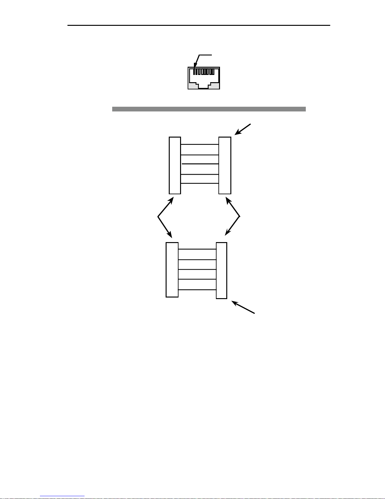
The maximum COM 2 cable length is 50 feet. Figure 2-1 illustrates the
required pin configuration.
Page 2-2
Page 20
REQUIREMENT/SPECIFICATIONS
Pin 1
RJ-45 CONSOLE PORT
RECEIVE
TRANSMIT
SIGNAL GROUND
DATA SET READY
DATA TERMINAL READY
CONSOLE PORT
RJ-45
TRANSMIT
RECEIVE
SIGNAL GROUND
DATA SET READY
DATA TERMINAL READY
RJ-45 TO 25 PIN
CABLE
4
1
5
2
6
1
4
5
2
6
FEMALE - 25 Pin
"D" Shell Connector
2
TRANSMIT
3
RECEIVE
7
SIGNAL GROUND
20 DATA TERMINAL READY
5
CLEAR TO SEND
LOCAL MANAGENT
CONSOLE
RECEIVE
2
TRANSMIT
3
5
SIGNAL GROUND
7
READY TO SEND
8
CLEAR TO SEND
You must properly configure your terminal to communicate with Local
Management. Table 2-2 lists the setup requirements for the local
management console. For more detailed setup information, the
keyboard map, or information on setting up a PC emulation, refer to
your specific terminal manual. If your terminal is a Digital Equipment
Corporation VT series terminal, press
RJ-45 TO 9 PIN
CABLE
Figure 2-1. Console Cable Pinouts
F3
to access the Setup Directory.
FEMALE - DB-9
(9-Pin Connector)
Page 2-3
Page 21

REQUIREMENT/SPECIFICATIONS
Table 2-2. Terminal Setup Requirements
Menu Function Selection
Display Columns 80 Columns
Setup: Controls Interpret Controls
Auto Wrap No Auto Wrap
Text Cursor Cursor
General Mode 7 Bit Control
Setup:
Cursor Keys Normal Cursor
Keys
Communications
Setup: Transmit Transmit = 9600
Receive Receive = Transmit
X=64 any option
Bits, Parity 8 Bits, No Parity
Stop Bit 1 Stop Bit
Local Echo No Local Echo
Port EIA Port, Data Leads
Only
DEC-423, Data
Leads only
Transmit any option
Auto Answerback No Auto Answerback
Keyboard Auto Repeat any option
Setup: Keyclick any option
Margin Bell Margin Bell
Warning Bell Warning Bell
Auto Answerback No Auto Answerback
Page 2-4
Page 22

REQUIREMENT/SPECIFICATIONS
2.3 OPERATING SPECIFICATIONS
Microprocessor:
Network Interfaces:
Ethernet: Standard IEEE 802.3
Token Ring: Standard IEEE 802.5
WAN: AT&T T7115
Intel RISC 80960 CF @24 MHz
National Semiconductor DP83932
SONIC
SPYDER-T
Standard RS530 (DB25)
Synchronous Interface supporting:
RS232: 9600 - 19.2Kbps
RS422/RS449: 9600-2.048 Mbps
V.35: 9600 - 2.048 Mbps
Optional T1-SRM Interface supporting:
FT1: 24 channels @ 56/64 Kbps
T1: 1.544 Mbps
Bridging:
Standard IEEE 802.1d
Standard IEEE 802.5 (Token Ring)
CPU Memory:
4 MBytes Dynamic RAM
(expandable to 12 MBytes)
Buffer Memory:
4 MBytes
2.3.1 Environmental Requirements
Operating Temperature: +5° to +40° C
Non-Operating Temperature: -30° to +40° C
Operating Humidity: 5 to 95% (non-condensing)
Page 2-5
Page 23

REQUIREMENT/SPECIFICATIONS
2.3.2 Safety
This unit meets the following safety requirements: UL 1950, CSA
C22.2 No. 950, and EN 60950; the EMI requirements of FCC Class A
and EN 55022 Class A; and the EMC requirements of EN 50082-1.
Warning: It is the responsibility of the person who sells the system to
which the ETWMIM will be a part to ensure that the total system meets
allowed limits of conducted and radiated emissions.
2.3.3 Physical
Dimensions: 11.5 H x 2.0 W x 13.4 D inches
(29.21 cm x 5.08 cm x 34.04 cm)
Weight:
Unit: 2.4 lbs.
Shipping: 4.9 lbs.
Page 2-6
Page 24

CHAPTER 3
INST ALLING THE ETWMIM
This section contains instructions for installing the ETWMIM. Verify
that all network design guidelines and site requirements listed in
Chapter 2, Installation Requirements/Specifications, are met
before installing the ETWMIM.
3.1 UNPACKING THE ETWMIM
Before installing the ETWMIM, visually inspect the unit and check
the contents of your shipping box with the list below.
• ETWMIM (1)
• set of release notes (1)
• disposable wrist strap (1)
• ETWMIM User’s Guide
• cable connection kit (1)
Warning: Electrostatic Discharge (ESD) can damage the ETWMIM.
Observe all precautions to prevent electrostatic discharges when
handling the ETWMIM. These precautions include wearing the
disposable wrist strap included in your shipping package, holding only
the edges of the board or the metal front panel, and not touching the
components or surface of the board.
To unpack the unit:
1) Carefully remove the ETWMIM from the shipping box.
2.) Remove the ETWMIM from the protective plastic bag.
Note: If you must set the ETWMIM down for any reason, place it back
inside the protective bag. This will help prevent ESD damage.
Contact Cabletron Systems Technical Support immediately if you
encounter any problems unpacking or installing the ETWMIM.
Page 3-1
Page 25
INSTALLING THE ETWMIM
3.2 SETTING THE CONFIGURATION SWITCHES
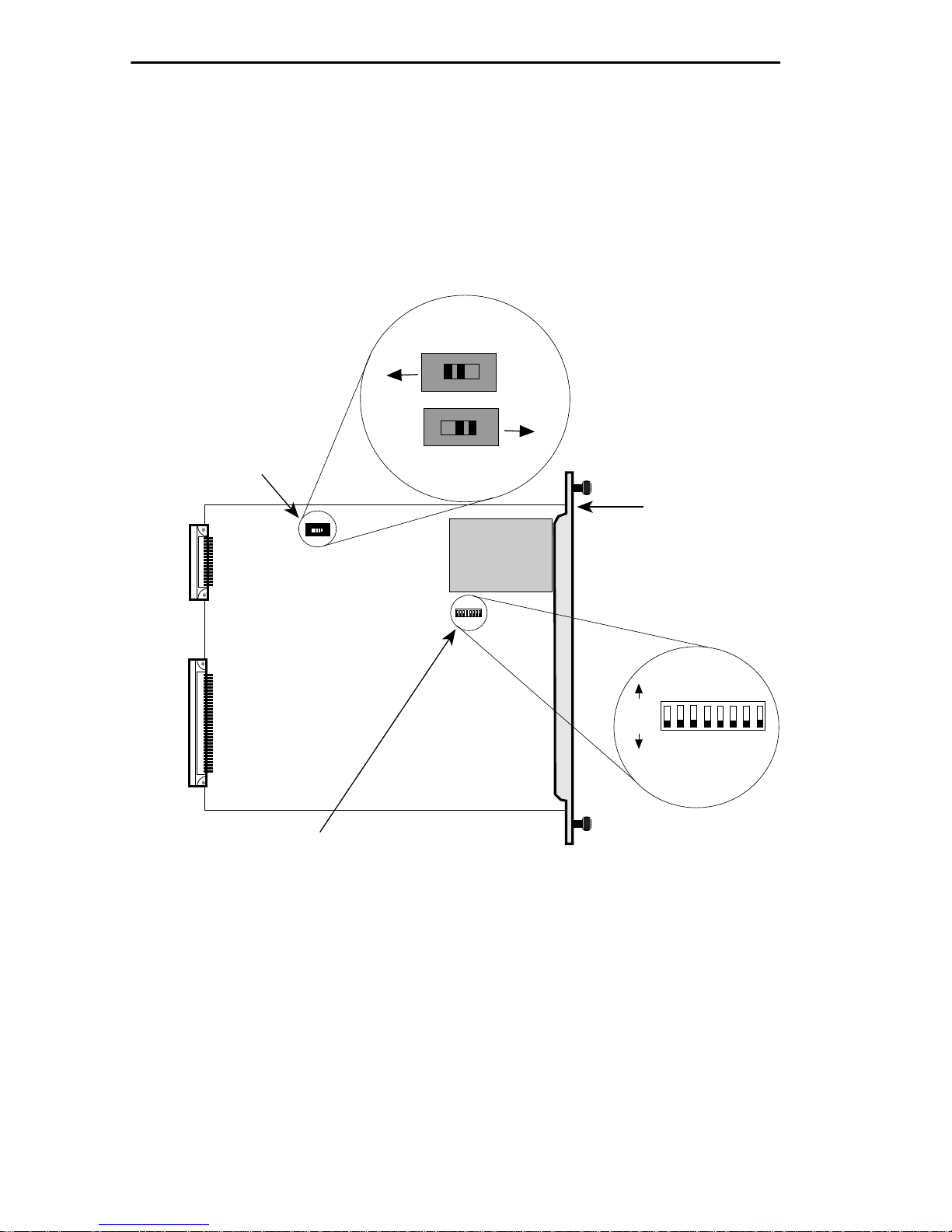
The ETWMIM has two configuration switches — a switch bank, and
an Ethernet connection slide switch. You must set these switches
before installing the ETWMIM. Figure 3-1 illustrates the location of
these items on the ETWMIM board.
Rear Panel
BackplaneConnection
Ethernet Connection
Switch (SW 4)
Front Panel
EPIM Connection
ETWMIM
Front Panel
Switch Bank (SW 2)
Figure 3-1. Location of Switches
ON
OFF
1 2 3 4 5 6 7 8
Refer to Table 3-1
For Settings.
Page 3-2
Page 26

INSTALLING THE ETWMIM
3.2.1 Setting the Switch Bank (SW2)
Switch Bank SW2 controls various functions in the ETWMIM. Table
3-1 lists these functions and possible switch settings.
Table 3-1. ETWMIM Switch Bank Settings
Switch Function
Settings
(* indicates factory default)
1 Clear NVRAM N/A (Toggle Switch)
2 bootp download N/A (Toggle Switch)
3 Ctron Use Only N/A
4 Token Ring
Speed
5 SYNC Port
Clear to Send
6 SYNC Port
Data Set Ready
7 T1 Clock
ON: 16 Mbits*
OFF: 4 Mbits
ON: CTS toggles with signal*
OFF: CTS forced on
ON: DSR toggle with signal*
OFF: DSR forced on
ON: Line Clock*
Source Select
OFF: Internal Generated Clock
Note: Check with the Service
Provider for Proper Setting
8 T1 Line Format ON: D4 Format
OFF: ESF Format*
Note: When using a toggle switch, move the switch to the opposite
position and power-up the board. For example, if the switch is in the
‘ON’ position, switch it to the ‘OFF’ position and leave it there. This
change in position activates the switch function.
Page 3-3
Page 27

INSTALLING THE ETWMIM
3.2.2 Ethernet Connection Switch (SW4)
Ethernet can connect to the ETWMIM in one of two ways — through a
front panel EPIM connection or through the backplane. If you want a
front panel EPIM connection, slide switch SW4 tow ard the front of the
unit. If you want Ethernet connection through the backplane, slide
switch SW4 toward the rear of the module.
Note: When set for the front panel, this switch turns the front panel
EPIM LED ON, regardless of whether an EPIM is installed or not.
3.3 INSTALLING THE ETWMIM
Depending on what you want to do with the ETWMIM, you must
follow a few hub configuration rules. When installing the ETWMIM
into your hub, keep the following in mind:
• If the ETWMIM is going to use the backplane A-channel
(Ethernet Channel) in your MMAC hub, the hub MUST have
an Ethernet management device (e.g., IRM, IRM-2, etc.) in the
far right slot.
• If the ETWMIM is going to use the front panel EPIM for
Ethernet connectivity, you DO NOT need an Ethernet
management device in your hub.
• If the ETWMIM is going to bridge Token Ring traffic, and you
are using a non-shunting MMAC, all Token Ring modules
MUST reside in slots adjacent to the ETWMIM.
After unpacking your ETWMIM, setting any configuration switches,
and deciding where to insert the board in the hub proceed as follows:
Note: We recommend powering-down your MMAC before installing or
removing ETWMIMs, even though they have “hot swap” capabilities.
1. Turn off the power to the MMAC. Remember that MMACs with
multiple power supplies have an ON/OFF switch for each supply.
2. Remove the selected blank panel from the MMAC.
Page 3-4
Page 28
INSTALLING THE ETWMIM
MMAC-8FNB
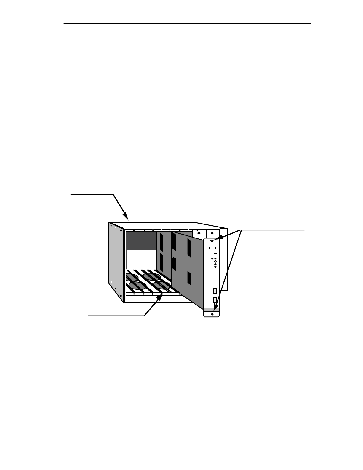
3. Holding the ETWMIM by the front panel or by the edges of the
circuit board, align the bottom and top edges of the card with the
slot guides in the MMAC chassis. Be sure that both the bottom and
top edges of the card rest in the guide slots. (See Figure 3-2).
4. Slide the ETWMIM into the MMAC until you feel it meet the
backplane. At this point, the front panel should be about 1/2 inch
from being flush with the rest of the modules in the MMAC.
5. Press gently to seat the module into the backplane. Do not try to
force the module into place or use the knurled knobs to draw the
module into the backplane. Forcing a misaligned module into place
can damage the ETWMIM or the MMAC backplane.
6. Turn on the MMAC chassis.
KNURLED KNOBS
IRM3TRMIM-22A
ETWMIM
BOARD SLOT
TOKEN RING
Figure 3-2. Installing the ETWMIM
3.4 INSTALLING AN EPIM
The ETWMIM allows for an optional Ethernet Port Interface Module
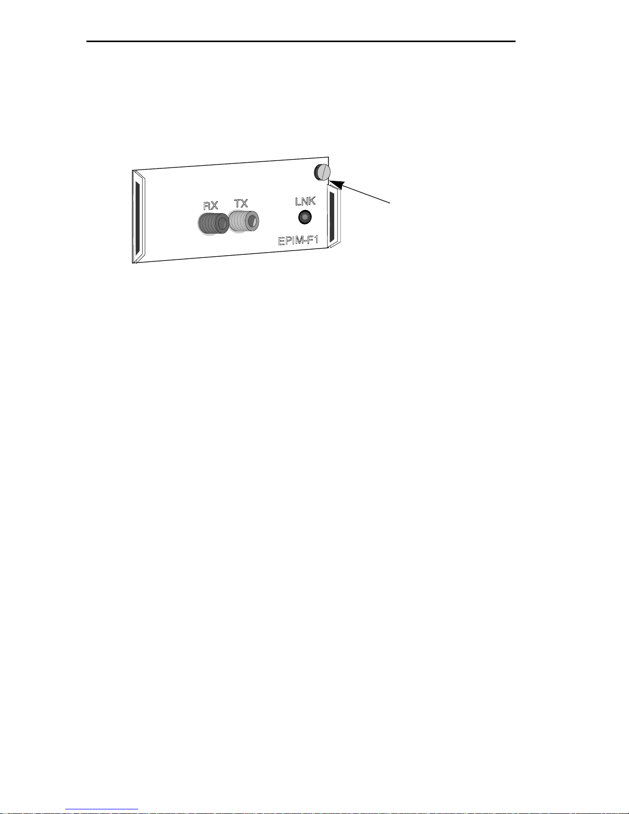
(EPIM). To install an EPIM refer to figure 3-3 and proceed as follows:
1. Remove the EPIM cover plate on the ETWMIM by untwisting the
coverplate screw.
2. Remove the EPIM from its protective package.
Page 3-5
Page 29
INSTALLING THE ETWMIM
3. Slide the EPIM into place, making sure the connectors on the rear
of the module and inside the ETWMIM attach properly.
4. Tighten the EPIM mounting screw.
Mounting Screw
Figure 3-3. EPIM Replacement
Note: See Appendix A for EPIM specifications and cabling information.
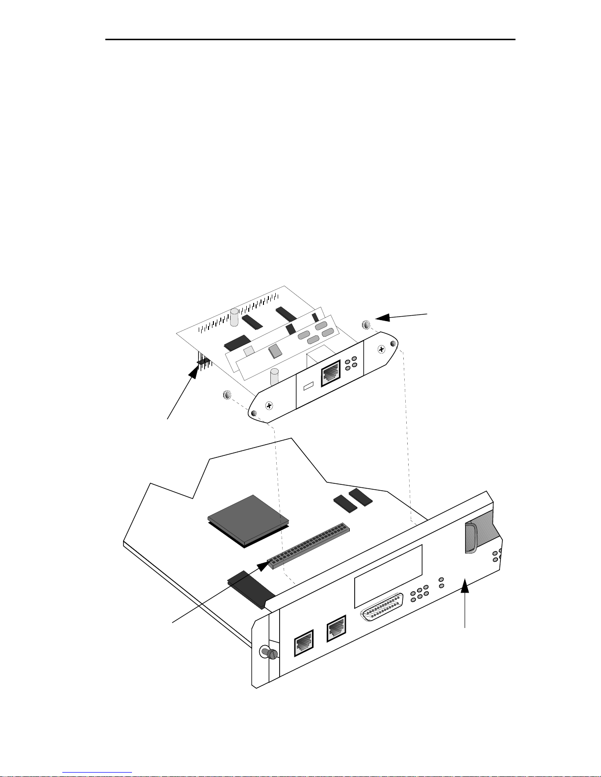
3.5 INSTALLING THE T1-SRM
The ETWMIM allows for an optional T1-SRM. To install this optional
T1 interface you need the following tools:
• disposable static wrist strap (provided with your ETWMIM)
• 5/16” nut driver, or equivalent.
After obtaining the necessary equipment, refer to Figure 3-4 and
proceed as follows:
1. Using the nut driver, remove the T1 cover plate lock-nuts from the
inside of the ETWMIM faceplate.
2. Remove the T1 cover plate and save it in the event you want to
remove the T1-SRM at a later date.
3. Remove the T1-SRM from its protective package.
4. Attach the T1-SRM such that the holes on the ends of the device
slide over the bolts on the back of the ETWMIM faceplate. (See
Figure 3-4.)
Page 3-6
Page 30
INSTALLING THE ETWMIM
EPIM
RWRP
CLN
NSRT
E
T
5. Insert the connector pins of the T1-SRM into the connector on the
ETWMIM mother board.
Caution: Make sure pins set properly in connector holes. Improper
connection can damage both the T1-SRM and the ETWMIM.
6. Press down on the back of the T1-SRM until the pins slide all the
way into the connector holes to ensure proper contact.
Note: Failure to make proper pin contact may result in poor network
performance, board malfunctions, or Local Management Configuration
Screen omissions.
7. Replace the lock-nuts and tighten them down with the nut-driver.
Lock-nut
Connector
Pins
Connector
TST
YEL
ALM
LOS
RED
L
B
O
-15
-7.5
0
dB
TOKEN RING WAN ETHERNET
C
O
M
2
ALM
T
1
SYNC
TST
CTS
DSR
STBY
LNK
RTS
DTR
S
Y
N
C
C
O
M
1
ETWMIM
Figure 3-4. Installing the T1-SRM
Page 3-7
Page 31

INSTALLING THE ETWMIM
3.6 CONFIGURING THE LBO SWITCH
The T1-SRM provides a Line Build Out (LBO) switch. The LBO switch
on the front of the T1-SRM is used to match the loss of the end-section
of the service provider’s (i.e. AT&T, Sprint, MCI, NYNEX, etc.) circuit.
The default setting from the factory is 0db, and in most installations it
should be left in this position. At the time of service installation, the
service provider may ask that the output of the T1-SRM be attenuated
because it is over-driving the T1 circuit. The service provider will
advise you if the setting should be -7.5db or -15db. Changing the LBO
from 0db to -7.5db or -15db decreases the output of the T1-SRM.
Warning: After the time of service installation, the LBO switch should
NEVER be adjusted. If you are experiencing a loss of signal or other
difficulties, it indicates a problem with the line or equipment. The LBO
switch should not be used to compensate for degradation of a circuit!
Table 3-2. LBO Switch Settings
Settings (dB) Attenuation
0 0 (no attenuation)
-7.5 ~2.3 times
-15 ~5.6 times
Page 3-8
Page 32
INSTALLING THE ETWMIM
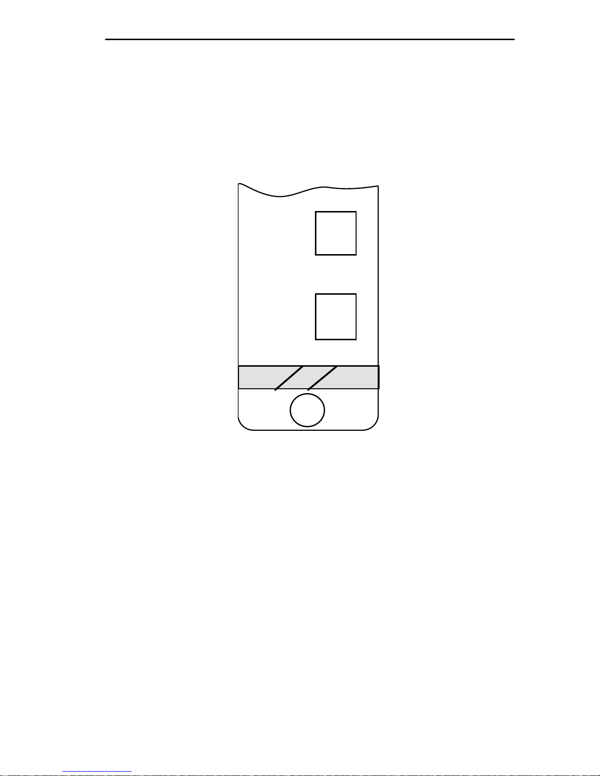
3.7 CONNECTING TO LOCAL MANAGEMENT
Access Local Management by attaching a management console to the
RJ-45 COM 2 port of the ETWMIM (see Figure 3-5). The console
connection supports a Digital Equipment Corporation VT200 or 300
series terminal or PC emulation of one of these terminals.
C
O
M
1
C
O
M
2
TOKEN RING
WAN
ETHERNET
Figure 3-5. COM Connections
Connect the console to the ETWMIM as follows:
1. Attach the male RJ-45 connector to the ETWMIM COM 2 port.
2. Attach the female end (25-pin or 9-pin, as applicable) to the COMM
port on the terminal.
3.8 FINISHING THE INSTALLATION
The ETWMIM is now ready for operation. Before placing the network
into service, test the installation thoroughly, making sure that all
stations are able to be addressed and that the ETWMIM and all
stations are indicating normal operation.
Page 3-9
Page 33
CHAPTER 4
USING LANVIEW
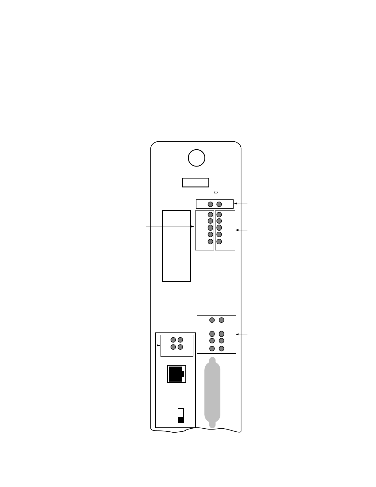
The ETWMIM uses Cabletron’s built-in visual diagnostic and status
monitoring system called LANVIEW. With LANVIEW, network
troubleshooting personnel can quickly scan LEDs to observe network
status, or diagnose network problems. Figure 4-1 displays the
LANVIEW LEDs on the ETWMIM.
ETWMIM
SN
Ethernet
Status LEDs
RESET
BOK ERR
STBY
RCV
XMT
CLN
EPIM
E
T
STBY
16MB
LWRP
NSRT
RWRP
System
Status LEDs
Token Ring
Status LEDs
T1 Port
Status LEDs
STBY
LNK
RTS
DTR
TST
YEL
ALM
LOS
RED
ALM
SYNC
TST
CTS
DSR
T
1
S
Y
N
C
-15
L
-7.5
B
O
0
db
Figure 4-1. LANVIEW LEDs
Sync. Port
Status LEDs
Page 4-1
Page 34

USING LANVIEW
4.1 SYSTEM STATUS LEDs
BOK (Board OK)
• Flashing (three times/second) - Indicates that the module is
running a self-test. This LED flashes three times/second during
the self-test, and then adjusts to the normal one time/second
rate.
• Flashing (one time/second) - Indicates that the module has
successfully completed its self-test and is ready for normal
operation.
ERR (Error)
• On - Indicates the detection of a hardware failure. This LED
should not be on during normal operations. If the problem
persists, contact Cabletron Systems Technical Support.
• Off - Indicates normal operating conditions.
4.2 ETHERNET STATUS LEDs
STBY (Standby)
Standby is an inactive state where the module is not passing data on
the station connection. Standby is set/reset via Local Management or
in-band network management.
• On - Indicates that the module is in Standby mode.
• Off - Indicates normal operation. The module is operational
and passing data on the Station port.
Page 4-2
Page 35

USING LANVIEW
RCV (Receive)
• Flashing - Indicate the ETWMIM is receiving a data packet
through the Ethernet port. The flash is pulse-stretched for
viewing effect.
• Off - Indicates the ETWMIM is not receiving data packets.
XMT (Transmit)
• Flashing - Indicates a data packet is being transmitted
through the Ethernet port. The flash is pulse stretched for
viewing effect.
• Off - Indicates the ETWMIM is not transmitting data packets.
CLN (Collision)
• Flashing - Indicates a detected collision. The flash is
pulse-stretched for viewing effect.
• Off - No collisions detected.
EPIM (Ethernet Port Interface Module)
• On - Indicates the Ethernet Connection Switch (SW4) is set to
the forward (EPIM) position.
• Off - Indicates the SW4 switch is set to the rear (backplane)
position.
Page 4-3
Page 36

USING LANVIEW
4.3 TOKEN RING STATUS LEDs
STBY (Standby)
Standby is an inactive state where the module is not passing data on
the ring. Standby is set/reset via in-band network management.
• On - Indicates that the module is in Standby mode.
• Off - Indicates normal operation. The module is operational
and passing data on the Station port.
16 Mbps (Ring Speed)
• On - Indicates that the module ring speed is set to 16 Mbps.
• Off - Indicates that the module ring speed is set to 4 Mbps.
LWRP (FNB Left Wrap)
The LWRP LED indicates the state of the FNB left (trunk) connection.
• On - Indicates that the left FNB ring connection has been set
to the wrap state by network management.
• Off - Indicates normal operation. The FNB left connection is in
a non-wrap state. When this LED is on, it indicates that the left
FNB ring connection has been set to the wrap state by network
management.
NSRT (Insert)
• On - Indicates that the module is inserted onto the ring via its
FNB Trunk connection. This is the normal operating condition.
• Off - Indicates that the module has been removed from the
ring.
Page 4-4
Page 37

USING LANVIEW
RWRP (FNB Right Wrap)
• On - Indicates that the FNB right (trunk) connection has been
set to the wrap state by network management.
• Off - Indicates that the FNB right (trunk) connection is in a
non-wrap state. This is the normal operating condition.
4.4 T1-SRM PORT STATUS LEDs
TST (Test)
• On - Indicates that the T1-SRM is in test mode. This LED ma y
indicate internal or external loop testing. For example, the
LED lights when the service provider loops up the ETWMIM or
the ETWMIM loops back (as with power up diagnostics).
• Off - Indicates normal operation.
LOS (Loss of Signal)
• On - Indicates that the T1-SRM is not receiving any pulses
from the T1 circuit.
• Off - Indicates normal operation.
YEL ALM (Yellow Alarm)
• On - Indicates that the remote T1-SRM is in red alarm. Check
the remote T1-SRM, port cable, the Line Build Out (LBO)
setting, the Timing Mode setting, or the ESF/D4 setting.
• Off - Indicates normal operation.
RED ALM (Red Alarm)
• On - Indicates a service provider system failure on the
incoming line.
• Off - Indicates normal operation.
Page 4-5
Page 38

USING LANVIEW
4.5 SYNCHRONOUS PORT STATUS LEDs
SYNC (Synchronous):
• On - Indicates that the SYNC port is active.
• Off - Indicates that the T1/SRM port is active.
STBY (Standby):
• On - All WAN bridge ports are in the non-forwarding state.
Possible causes of this condition are: redundancy detected by
Spanning Tree , data link la yer down, physical la yer down, port
disabled, problem in telephone circuit, or improper
configuration.
• Blinking - Some WAN bridge ports are in the forw arding state
and some WAN bridge ports are in the non-forwarding state.
• Off - All WAN bridge ports are in the forwarding state.
TST (Test)
• On - Indicates that the SYNC port is in test mode.
• Off - Indicates that the SYNC port is in non-test mode.
LNK (Link)
• On - Indicates a clock is being received from the DCE.
• Off - Indicates no clock from the DCE.
CTS (Clear to Send)
• On - Indicates that the DCE is ready to receive data from the
SYNC Port, or that the Force CTS True field (refer to the WAN
Physical Configuration screen) is set to YES (On).
• Off - A valid CTS is not being received from the DCE. Check the
cabling or check if the DCE is powered on.
Page 4-6
Page 39

USING LANVIEW
RTS (Request to Send)
• On - Indicates the ETWMIM is ready to send data to the DCE.
• Off - Indicates the ETWMIM is not ready to send data to the
DCE.
DSR (Data Set Ready)
• On - Indicates that the DCE is ready to operate, or that the
F orce DSR True field (refer to the W AN Physical Configuration
screen) is set to YES (on).
• Off - A valid DSR is not being received from the DCE. Check
the cabling or check if the DCE is powered up.
DTR (Data Terminal Ready)
• On - ETWMIM is operational and ready to generate or receive
control signals (such as RTS or CTS).
• Off - ETWMIM is not operational.
Page 4-7
Page 40

CHAPTER 5
LOCAL MANAGEMENT
Cabletron Systems ETWMIM Local Management provides unique
management and control capabilities for Cabletron Systems
ETWMIM. Local Management supplies the tools to manage the
ETWMIM and all of its attached segments. You can:
• assign an IP address and subnet mask
• select a default gateway
• set interface parameters for the COM 2 port
• control access to the ETWMIM through the community names
established in the Community Names Table
• designate which Network Management Workstations receive
traps from the device
• configure the optional T1-SRM WAN interface
• navigate through the Management Information Base (MIB),
and manage the objects within it from a remote location. Given
the appropriate security level, you can access the MIB from the
ETWMIM through SNMP Tools.
5.1 TERMINAL CONFIGURATION
The Local Management terminal must be a VT220, VT320 or
equivalent. You must configure the terminal as described in Chapter 2
in order to communicate with Local Management. For instructions on
setting up your terminal, refer to your terminal manual.
Page 5-1
Page 41

LOCAL MANAGEMENT
5.2 ACCESSING LOCAL MANAGEMENT
After ensuring proper terminal configuration, and correct physical
cable connections, you can access ETWMIM Local Management.
To access Local Management:
1. Turn the terminal on. The ETWMIM Password screen, Figure 5-1,
appears.
ETWMIM LOCAL MANAGEMENT
Cabletron ETWMIM Revision 00.00.00
CABLETRON Systems, Incorporated
35 Industrial Way, P.O. Box 5005
Rochester, NH 03867-5005 USA
(603) 332-9400
(c) Copyright CABLETRON Systems Inc. 1994
ETWMIM F/W Version: 00.00.00
Boot EPROM Version: 00.00.00
ETWMIM Board Rev#: 0
Enter USER PASSWORD:
Figure 5-1. ETWMIM Password Screen
2. Enter your Password. The factory default password for super-user
access is a carriage return <CR>.
Note: Your password is one of the community names specified in the
Community Name Table. Access to certain Local Management
capabilities depends on the degree of access accorded to that community
name. See Section 5.3.
Page 5-2
Page 42

LOCAL MANAGEMENT
3. Press Return.
• If your password entry is invalid, the terminal beeps and the
cursor returns to the beginning of the password entry field.
• If your password is valid, the associated privilege appears
briefly on the screen, and then the ETWMIM Local
Management Feature Selection screen, Figure 5-2, appears.
ETWMI M LOCAL MA NAGE MENT
Cablet ron ET WMI M Revision 00.00.00
FEATURE SELECT ION
F6 COMMUNITY NAME TABLE
F7 IP ADDR ESS ASSIGNMENT
F8 C OMP ON ENT TR A P TABLE
F9 SNMP TOOL SUPPORT
F1 0 COM MAND L INE I NT ERFACE
WAN CONFIGURATION
E XIT LIM SERVICE
Figure 5-2. Feature Selection Screen
4. Use the arrow keys to highlight a screen option, and press Return
(or simply press the corresponding Function key). The desired
screen appears.
5.3 COMMUNITY NAME TABLE
The Community Name Table Option lets you set community names.
Community names serve two purposes — they act as passwords to
Local Management, and as agents of security control to your
ETWMIM. You control ETWMIM access by establishing up to four
different levels of security authorization (BASIC-READ , READ-ONLY,
READ-WRITE, and SUPER-USER).
If you have super-user access, you can change the existing passwords
by entering new community names. Only super-user community
names accord full management privileges.
Page 5-3
Page 43

LOCAL MANAGEMENT
5.3.1 Accessing the Community Name Table Screen
To access the Community Name Table screen from the Feature
Selection screen:
• Use the arrow keys to highlight the Community Name Table
option and press the Return key, or press F6. The Community
Name Table screen, Figure 5-3, appears.
ETWMIM LOCAL MANAGEMENT
Cabletron ETWMIM Revision 00.00.00
COMMUNITY NAME TABLE
<< PASSWORD AUTHORIZATION = SUPER-USER >>
NOTE: S/U names are LOCAL passwords
Community Name
public
public
public
public
SAVE IP TABLE TRAP TABLE SNMP TOOLS CLI RETURN
F6
F7
F8
Access
BASIC-READ
READ-ONLY
READ-WRITE
SUPER-USER
F9
F10
Figure 5-3. Community Name Table Screen
5.3.2 Community Name Table Screen Fields
The following briefly explains each field on the Community Name
Table screen.
Community Name
Displays the user-defined name through whic h a user can access Local
Management for the ETWMIM. Any community name assigned here
acts as a password to Local Management.
Page 5-4
Page 44

LOCAL MANAGEMENT
Access
Indicates the access status accorded each community name. Possible
status conditions are:
BASIC-READ This status provides limited read-only access to
the ETWMIM. This does not include access to
security protected fields of upper levels
(read-only, read-write, or super-user).
READ-ONLY This status allows for extended read-only
access to ETWMIM/Local Management fields,
but excludes access to security protected fields
of upper levels (read-write or super-user).
READ-WRITE This status provides read and write access to
ETWMIM/Local Management fields, excluding
fields that are security protected fields for
super-user.
SUPER-USER This status provides read-write access to the
ETWMIM and allows changes to all modifiable
parameters including: community names, IP
addresses, traps, and SNMP objects.
5.3.3 Editing the Community Name Table Screen
The password that you use to access Local Management at the
Password screen must have Super-User access for Community Name
Table edits to take effect. A password of either BASIC-READ,
READ-ONLY, or READ-WRITE access displays the message
“AUTHORIZATION PROHIBITS ACCESS”, and does not include
editing capabilities.
Caution: Any community name assigned in the Community Name
Table is a password to its corresponding level of access to Local
Management. The community name assigned super-user access is the
only one that provides complete access to Local Management.
Page 5-5
Page 45

LOCAL MANAGEMENT
To make changes to the Community Name Table Screen:
1. Using the arrow keys, highlight the Community Name field
adjacent to the desired access level.
2. Enter the password, up to 32 characters in length, into the field.
3. Press the Return key.
4. Repeat steps 1 - 3 for editing any of the other community names.
5. Using the arrow keys, highlight SAVE at the bottom of the screen
and press the Return key (or press F6). The message “SAVED
OK”, appears. The ETWMIM saves the community names to
memory and implements their modes of access.
Please note that the first time you try to exit the screen without
saving your changes, Local Management displays a “NOT
SAVED?” message above the SAVE command. If you proceed to
exit without saving, you lose all edits.
6. Exit the screen by either pressing the appropriate Function key
or by using the arrow keys to highlight RETURN and pressing the
Return key. The latter exits you to the Feature Selection screen.
5.4 CONFIGURING THE ETWMIM
The ETWMIM Configuration screen allows you to assign IP Addresses
and Subnet Masks. The Configuration screen also allows you to set the
Default Gateway.
Page 5-6
Page 46

LOCAL MANAGEMENT
5.4.1 Accessing the Configuration Screen
T o access the Configuration screen from the Features Selection screen:
• Use the arrow keys to highlight the IP Address Assignment
option and press the Return key, or press F7. The
Configuration screen, Figure 5-4, appears.
ETWMIM LOCAL MANAGEMENT
Cabletron ETWMIM Revision 00.00.00
CONFIGURATION
I/F
ENET
TR
SAVE IP COMMUNITY NAMES TRAP TABLE SNMP TOOLS CLI
F6
IP Address
0.0.0.0
0.0.0.0
Default Gateway: 0.0.0.0
COM-1 Application: OFFLINE
COM-2 Application: CONSOLE Baud Rate: 9600 --ACTIVE--
F7 F9 F10
SubNET Mask
0.0.0.0
0.0.0.0
F8
MAC Address
00-00-1d-06-f8-d8
00-00-b8-60-1f-9b
Figure 5-4. Configuration Screen
5.4.2 Configuration Screen Fields
The following briefly explains each field on the Configuration screen.
I/F
Gives the number of the interface corresponding to the channel over
which packets with that IP address are passing. There is an ENET
(Ethernet) and a TR (Token Ring) channel.
IP Address
Displays the IP Address of the Ethernet and Token ring ports.
SubNET Mask
Displays the SubNET Mask for the ETWMIM. A subnet mask is a
32-bit quantity which “masks out” the network bits of the IP address.
This is done by setting the bits in the mask to 1 when the network
treats the corresponding bits in the IP address as part of the network
or subnetwork address, or 0 if the bit identifies the host.
Page 5-7
Page 47

LOCAL MANAGEMENT
MAC Address
Displays the physical address associated with the interface.
Default Gateway
Displays the default gateway for the ETWMIM. This field displays
0.0.0.0 until you enter an appropriate value. The Default Gateway
identifies the Default Gateway Device that will forward packets to
other IP subnetworks.
COM 1 Application
Displays the port’s application setting as OFFLINE.
COM 2 Application
Displays the port’s application setting as CONSOLE.
Baud Rate
Displays the Baud Rate setting of the device attached to the ETWMIM
through that serial port. The setting for COM 2 is 9600. A flashing
-ACTIVE- appears after the 9600
5.4.3 Setting the IP Address Table and Subnet Mask Field
To set the IP Address Table and subnet mask fields:
1. Using the arrow keys, highlight one of the IP Address fields.
2. Enter the IP address into this field. The format for this entry is
XXX.XXX.XXX.XXX, with values for XXX being from 0 to 254.
Local Management does not accept non-numerics or adjacent dots.
If the entry does not have three dots, Local Management rejects it
and re-displays the old value.
3. Press the Return key. The screen displays the IP address and also
generates and displays the natural subnet mask.
4. Should you need to modify the subnet mask, use the arrow keys to
highlight the Subnet Mask field.
5. Enter the Subnet Mask into this field. The format for this entry is
XXX.XXX.XXX.XXX with values for XXX being from 0 to 255.
6. Press the Return key.
Page 5-8
Page 48

LOCAL MANAGEMENT
7. Using the arrow keys, highlight the SAVE IP option and press the
Return key, (or press F6). The message “SAVED OK” appears and
Local Management saves the changes to memory.
Note: The first time you try to exit the screen without saving your
changes, Local Management displays a “NOT SAVED?” message. If
you proceed to exit without saving, you lose all edits.
5.5 SETTING THE TRAP TABLE
As an SNMP compliant device, the ETWMIM can authenticate an
SNMP request. The Trap Table defines the management stations that
will receive SNMP Traps for alarm/event notification.
5.5.1 ETWMIM Trap Table Screen
To access the Trap Table screen from the Features Selection screen:
1. Use the arrow keys to highlight the Component Trap Table
option and press the Return key, or press F8. The Trap Table
screen, Figure 5-5, appears.
ETWMIM LOCAL MANAGEMENT
Cabletron ETWMIM Revision 00.00.00
SNMP Community Name
<CR>
<CR>
<CR>
<CR>
<CR>
<CR>
<CR>
<CR>
TRAP TABLE
Traps
Trap IP Address
N
N
N
N
N
N
N
N
0.0.0.0
0.0.0.0
0.0.0.0
0.0.0.0
0.0.0.0
0.0.0.0
0.0.0.0
0.0.0.0
SAVE COMMUNITY NAMES IP TABLE SNMP TOOLS CLI RETURN
F6 F7 F8 F9 F10
Figure 5-5. Trap Table Screen
Page 5-9
Page 49

LOCAL MANAGEMENT
5.5.2 Trap Table Screen Fields
SNMP Community Name
Displays the Community Name to be included in the trap message,
which is sent to the Network Management Station with the associated
IP address.
Traps
Enables transmission of the traps to the network management station
with the associated IP Address. Select Y to enable or N to disable.
Trap IP Address
Indicates the IP Address of the workstation to receive traps from the
ETWMIM.
5.5.3 Configuring the Trap Table
1. Using the arrow keys, highlight the SNMP Community Name
field and enter the name of that field.
2. Press the Return key.
3. Using the arrow keys, highlight the Traps field and enter Y (or y)
to send alarms from the ETWMIM to the workstation, and N (or n)
to prevent alarms from being sent.
4. Press the Return key.
5. Use the arrow keys to highlight the appropriate Trap IP Address
field.
6. Enter the IP Address of the workstation to send traps using this
field. The format for this entry is XXX.XXX.XXX.XXX, with the
value of XXX ranging from 0 to 254, and three dots, or else it
returns to the beginning of the field.
7. Using the arrow keys, highlight the SAVE option and press
Return (or press F6). The message “SAVED OK” appears.
Note: The first time you try to exit the screen without saving your
changes, Local Management displays a “NOT SAVED?” message. If
you proceed to exit without saving, you lose all edits.
Page 5-10
Page 50

LOCAL MANAGEMENT
8. Exit the screen by either pressing the appropriate Function key
or by using the arrow keys to highlight RETURN and pressing the
Return key. The latter will exit you to the Feature Selection
screen.
Alarms for these traps will now be sent to the designated IP addresses
from the ETWMIM.
5.6 SNMP TOOLS
This section describes specific commands and features within the
SNMP Tools screen. This screen allows you to access Management
Information Bases (MIBs), and varies according to your level of
security access.
The following descriptions outline the super-user management
capabilities. From SNMP Tools you can:
• review specifics about object identifiers (OIDs)
• edit configurable OIDs
• view OIDs sequentially from the originally requested OID.
5.6.1 Accessing The SNMP T ools Screen
To access the SNMP Tools screen:
1. From the Features Selection screen, use the arrow keys to
highlight the SNMP Tools Support option.
2. Press the Return key. The SNMP Tools screen, Figure 5-6,
appears.
Page 5-11
Page 51

LOCAL MANAGEMENT
GET SET GETNEXT WALK RECALL-OID STEP CYCLES REPEAT
F6 F7 F8 F9
Figure 5-6. SNMP Tools Screen
ETWMIM LOCAL MANAGEMENT
Cabletron ESXMIM Revision 0.00.00
SNMP TOOLS
COMMUNITY NAME: public
OID PREPEND: 1.3.6.1
RETURN
F10
5.6.2 SNMP Tools Screen Fields
The following describes the SNMP Tool screen fields and commands.
COMMUNITY NAME
Identifies the community name MIB access level password.
OID PREPEND
Specifies the number prefix common to all object identifiers (OIDs)
found in a MIB. The prefix ‘1.3.6.1’ is the default. You can modify this
field to suit your needs.
GET
Allows you to retrieve MIB objects, one at a time, using SNMP
protocol.
SET
Lets you edit modifiable MIB objects, using SNMP protocol.
GETNEXT
Displays the next OID in the MIB tree by getting the next SNMP OID
from a remote agent.
Page 5-12
Page 52

LOCAL MANAGEMENT
WALK
Scrolls you through the MIB, leaf by leaf, from a user-specified object
identifier. Leaves are objects, or instances of objects. After initializing
a walk you see the following categories for each entry:
• Specified OID — identifies the number tag for that OID.
• Size — gives the number of bytes required to store the object.
• Data Type — gives the object’s variable type (e.g ., int=integer).
• Data Value — displays what the object identifier represents.
RECALL-OID
Recalls from memory the last OID used since powering up the board
or re-entering the SNMP Tools screen.
STEP
Displays the MIB, step by step, with specific OID details.
CYCLES
Allows you to specify the number of GETNEXT requests to walk
through and how much time elapses between each request.
REPEAT
Repeats the Get command, allowing you to monitor any changes to a
specific OID.
5.6.3 The Security Access Level
Each MIB component that the ETWMIM supports (e.g., RMON, DLM,
etc.) has its own “password” for each possible level of access (ranging
from Basic Read-Only to Super-User). Most MIB component
Community Names default to “public.”
Note: A complete list of Super-User Community Names (also called
Community Strings) resides in the Cabletron proprietary chassis MIB.
The MIB group chCompName provides the names of the MIB
components. The MIB group chCompSUCommStr provides individual
MIB component Community Names/Strings.
The component information corresponds numerically – by last digit. In
other words, each instance (i.e., OID element) in the chCompName
group indicates its match in the chCompSUCommStr group.
Page 5-13
Page 53

LOCAL MANAGEMENT
In order to access a specific MIB’s components, you must set the
appropriate MIB password in the COMMUNITY NAME field.
Note: The default Super-User password (public) allows you to access
most MIB components. To change the SNMP Tools screen
COMMUNITY NAME field, you must have Super-User access to Local
Management.
To set the SNMP Tools screen COMMUNITY NAME:
1. Use the arrow keys to highlight the field to the right of
COMMUNITY NAME.
2. Enter the Community Name necessary for Super-User access for
any specific MIB (e.g., channel A DownloadMIB).
3. Press the Return key. The Community Name changes.
5.6.4 Getting And Setting OIDs
To get an OID:
1. Use the arrow keys to highlight GET, or press the F6 function key.
2. Press the Return key. “<GET> OID (=|F9):” appears.
3. Enter an OID either by:
• using the keyboard to enter the OID.
Shortcut: Save yourself some keystrokes by typing the OID minus
the OID’s prepend (i.e., given an OID prepend of 1.3.6.1, you enter
2.1.1.4.0, and the Local Management gets the MIB II sysContact
OID 1.3.6.1.2.1.1.4.0).
• pressing F9 to recall an OID already entered, and using the
keyboard to modify the recalled OID as necessary.
• entering an ‘=’ and the OID suffix (e.g., if you enter =2.1.1.4.0,
the OID = 1.3.6.1.2.1.1.4.0). This allows you to digress and not
use the prepend.
Page 5-14
Page 54

LOCAL MANAGEMENT
4. Press the Return key. If there is no instance of that OID, the
ETWMIM displays “MIB_NO_INSTANCE.” Otherwise, the
ETWMIM displays that OID’s data type, length, and value.
To get the next OID:
1. Highlight GETNEXT, using the arrow keys.
2. Press the Return key. “<GETNEXT> OID (=|F9):” appears.
3. Enter the OID.
4. Press the Return key. If that OID does not exist, the ETWMIM
displays “MIB_NO_INSTANCE”. Otherwise the ETWMIM
displays that OID’s data type, length, and value.
Shortcut: If you have previously entered an OID, press F9 to
recall that entry. You can use the arrow keys to modify the recalled
OID, or if you have not previously entered the OID, type the OID
minus the OID’s prepend.
To set an OID (parentheses provide an example for you to follow):
1. Highlight SET, using the arrow keys.
2. Press the Return key. “<SET> OID (=|F9):” appears.
3. Enter an OID. (1.3.6.1.2.1.1.4.0)
4. Press the Return key. If that OID does not exist, the ETWMIM
displays “MIB_NO_INSTANCE”. Otherwise the ETWMIM
displays:
{INteger String Null OId IPaddress Counter Gauge Timeticks
OPaque}
“DATA TYPE (name):”.
Shortcut: If you have previously entered an OID, press F9 to
recall that entry. You can use the arrow keys to modify the recalled
OID, or if you have not previously entered the OID, save yourself
some keystrokes by typing the OID minus the OID’s prepend.
Page 5-15
Page 55

LOCAL MANAGEMENT
5. Enter the OID’s Data Type. (the sysContact Data Type is String.)
Note: When setting a String, SNMP tools requests the kind of data
you plan to enter — HEX or ASCII. (In this example choose ASCII.)
6. Press the Return key. The ETWMIM displays “SNMP OID
DATA.”
7. Enter the Data, or value of the OID. (Type in a sysContact. This
OID allows for a String of up to 12 characters.)
8. Press the Return key. If the ETWMIM accepts the entry, it
displays “<SET> OPERATION CODE: XXXX <OK>”; otherwise,
an error message appears.
5.6.5 Scrolling Through MIB OIDs
Viewing several object identifiers at one time allows you to quickly
scan a MIB for the information that you need. The SNMP Tools screen
provides several scroll options:
• WALK — scrolls through OIDs sequentially, from the initial
OID.
• CYCLE — allows you to specify how many GETNEXT
commands to cycle through for one OID.
• STEP — pages through the MIB, one OID at a time.
To walk through the MIB:
1. Highlight WALK, using the arrow keys.
2. Press the Return key. “<INITIAL> OID (=|F9):” appears.
3. Enter the OID.
4. Press the Return key. Local Management begins walking through
the sublayers of the MIB available from the specified OID. Each
OID in the list displays the specified OID, its size, its data type, and
the data value.
5. Press any key to stop the walk, or wait for “***MIB WALK
COMPLETED***” to appear on the screen.
Page 5-16
Page 56

LOCAL MANAGEMENT
To cycle through:
1. Highlight CYCLES, using the arrow keys.
2. Press the Return key.
3. Enter the number of OID cycles that you want to scroll through
after “ENTER <GETNEXT> CYCLE COUNT:”.
4. Press the Return key.
5. Enter how many seconds delay that you want between GETNEXT
requests after “ENTER CYCLE DELAY (secs):”.
6. Press the Return key.
7. “<GETNEXT> OID (=|F9):” appears.
8. Enter the OID.
9. Press the Return key.
To step through:
1. Highlight GETNEXT, using the arrow keys.
2. Enter the OID (only the suffix is necessary).
3. Press Return. The initial OID details, including its size, data type,
and data value, appear.
4. Highlight STEP, using the arrow keys.
Press the Return key to page through the MIB to the next OID.
Page 5-17
Page 57

LOCAL MANAGEMENT
5.7 CONFIGURING WAN PHYSICAL ATTRIBUTES
The WAN Physical Configuration screen allows you to define the
physical attributes of your WAN interface.
5.7.1 Accessing the WAN Configuration Screen
To access the WAN Physical Configuration screen from the Features
Selection screen use the arrow keys to highlight the WAN
CONFIGURA TION option and press the Return key. The W AN
Physical Configuration screen, Figure 5-7, appears.
Note: T1 information fields appear on the WAN Physical Configuration
screen only after you install the optional T1-SRM module.
ETWMIM LOCAL MANAGEMENT
Cabletron ETWMIM Revision 00.00.00
WAN PHYSICAL CONFIGURATION
Active WAN Port: T1
Default WAN Port: T1
SYNC Port Type: V.35
Force CTS True: Yes
Force DSR True: No
SAVE
F6
WAN INT CONFIG
01-08
09-16
17-24
T1 Timeslot View: Active
T1 Line Coding: B8ZS
T1 Frame Type: ESF
T1 Xmit Clk Src: LOCAL TIMING
T1 Timeslot Configuration
00 00 00 00 00 00 00 00
00 00 00 00 00 00 00 00
00 00 00 00 00 00 00 00
RETURN
Figure 5-7. WAN Physical Configuration Screen
5.7.2 WAN Physical Configuration Screen Fields
Active WAN Port
Displays the active WAN port. In future ETWMIM releases, this field
will provide port redundancy information.
Page 5-18
Page 58

LOCAL MANAGEMENT
Default WAN Port
Displays the default WAN port used for the WAN connection. The
selections toggle between SYNC and T1.
SYNC Port Type
Displays the Sync Port electrical interface type. The selections toggle
between V.35, RS422, RS232, and NONE. This field always displays a
Sync Port Type, even if the Sync Port is not the active WAN port. To
use X.21 or RS530, select RS422 and use the proper Interface Cable
part numbers. The default setting for this field is V.35. Table 5-1 lists
the available Interface Cable part numbers.
Table 5-1. Cabletron Interface Cables
Interface Type Cabletron Part Number
V.35 (CCITT V.35) 9372080
RS422 (EIA 449) 9372078
RS232 (EIA 232) 9372079
X.21 (CCITT X.21) Call Cabletron Systems for
part number.
RS530 (EIA 530) 9372079
Force CTS True
Displays the source of the Clear To Send (CTS) signal. The CTS signal
is an input to the ETWMIM. The ETWMIM can either use or ignore
the CTS signal. You can toggle the selections between YES and NO.
The YES (On) setting indicates that the ETWMIM ignores the CTS
signal from an external DCE (Data Communications Equipment). The
NO (Off) setting indicates that the CTS signal is received from an
external DCE. The default setting is NO.
Force DSR True
Displays the source of the Data Set Ready (DSR) signal. You can
toggle the selections between YES and NO. The YES (On) setting
indicates that the DSR is internally “Forced True” (from the
ETWMIM). The NO (Off) setting indicates that the DSR signal is
received from an external DCE. The default setting is NO.
Page 5-19
Page 59

LOCAL MANAGEMENT
Note: Settings for the following fields are determined by the service
provider settings. Cabletron suggests that you consult the service
provider (i.e. AT&T, Sprint, MCI, NYNEX, etc.) for the correct settings.
T1 Timeslot View
Displays the status of the T1 Timeslot Configuration Table. The
selections for this field toggle between Active and New. The Active
setting displays current Timeslot Configuration Table settings. The
New setting allows you to change Timeslot Configuration Table
settings. The default setting for the Timeslot Configuration T able is all
Timeslots not assigned.
T1 Line Coding Physical
Displays the line coding for the physical T1 line. The selections toggle
between B8ZS, and AMI. The default setting for this field is B8ZS.
T1 Frame Type
Displays the T1 Frame type. You set the T1 Frame Type by changing
the hardware configuration switch. Refer to Chapter 3.2 Setting the
Configuration Switches. The available T1 Frame Types are ESF
and D4. The default setting for this field is ESF.
T1 Xmit Clk Src
Displays the T1 Transmit Clock Source. You set the T1 Xmit Clk Src
by changing the hardware configuration switch. Refer to Chapter 3.2
Setting the Configuration Switches. The selections for this field
are Loop Timing (Extracted Line Data) and Local Timing (Internal
Clock). The default setting for this field is Loop Timing.
5.7.3 Setting the Active WAN Port Field
To set the Active WAN Port:
1. Use the arrow keys to highlight the Active WAN Port field.
2. Press the Return key to toggle the selections.
3. After reaching the desired selection, use the arrow keys to
highlight the SAVE command.
4. Press the Return key. The message “SAVE DONE” appears and
Local Management saves the changes to memory.
Page 5-20
Page 60

LOCAL MANAGEMENT
5.7.4 Setting the SyncPort Type Field
To set the SyncPort type:
1. Use the arrow keys to highlight the SyncPort Type field.
2. Press the Return key to toggle the selections.
3. After reaching the desired selection, use the arrow keys to
highlight the SAVE command.
4. Press the Return key. The message “SAVE DONE” appears and
Local Management saves the changes to memory.
5.7.5 Setting WAN Physical Configuration Screen Fields
To set a WAN Physical Configuration screen field:
1. Use the arrow keys to highlight the WAN Physical Configuration
screen field you want to change.
2. Press the Return key to toggle the selections.
3. When the desired selection appears, use the arrow keys to
highlight the SAVE command.
4. Press the Return key or press F6. The message “SAVE DONE!”
appears and Local Management saves the changes to memory.
5.7.6 Setting the T1 Timeslot Configuration T able
The T1 Timeslot Configuration Table allows you to configure how your
ETWMIM utilizes the T1 line. The configuration table consists of 24
Timeslots. You must assign each Timeslot an Interface number
(04-28, or 00 if the Timeslot is not used).
Note: The ETWMIM automatically assigns Interface 01 for Ethernet,
Interface 02 for Token Ring, and Interface 03 for the SYNC port.
When you lease an entire T1 line , you can use all 24 Timeslots (the full
T1 bandwidth). If you lease only a fraction of the T1, the service
provider will tell you which Timeslots to use.
Page 5-21
Page 61
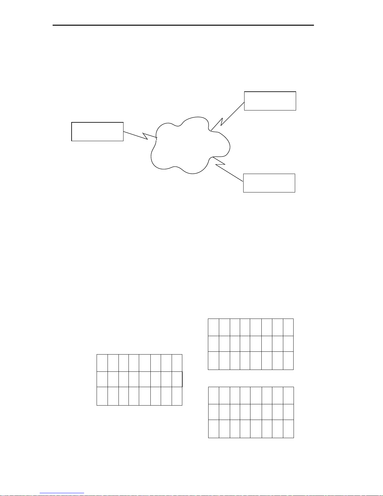
LOCAL MANAGEMENT
You can utilize Timeslots any way you choose. For example, if your
ETWMIM has access to a full T1 (24 Timeslots), and you want to
communicate with two other ETWMIMs, your configuration could look
like figure 5-8.
ETWMIM#2
16 Channels
ETWMIM#1
Telco
24 Channels
Cloud
ETWMIM#3
8 Channels
Figure 5-8. Sample Timeslot Configuration
Figure 5-9 shows a sample configuration for three ETWMIMs. Of the
24 Timeslots, ETWMIM#1 uses 16 to communicate with ETWMIM#2
and the remaining 8 to communicate with ETWMIM#3. This
configuration can vary tremendously, depending on how the Telco
carrier maps out the T1 Timeslots. Your service provider will tell you
which Timeslots are active.
01-08
09 -16
17 -24
04
04
05
04 04
04 04
05 05
04 04
04 04
05 05
04 04 04
04 04 04
05 05 05
01-08
09 -16
17 -24
01-08
06
00
00
04
06 06
00 00
00 00
ETWMIM#3
04 04
06 06
00 00
00 00
04 04
06 06 06
00 00 00
00 00 00
04 04 04
ETWMIM#1
Figure 5-9. Sample Configuration
Page 5-22
09 -16
17 -24
04
00
04 04
00 00
ETWMIM#2
04 04
00 00
04 04 04
00 00 00
Page 62

LOCAL MANAGEMENT
ETWMIM#1 is using the full T1, so all the Timeslots must have an
Interface assignment. ETWMIM#2 and ETWMIM#3 only use a
fraction of the T1, but the quantity of Timeslots must match those of
ETWMIM#1. Unused Timeslots receive an Interface number of 00.
Note: The Interface numbers of ETWMIM#1 and ETWMIM#3 do not
have to match. Only the quantity and specific Timeslot must match
(the service provider assigns the Timeslot).
To set the Timeslot Configuration Table:
1. Use the arrow keys to highlight the Active setting in the T1
Timeslot View field
2. Press the Return key.
3. The T1 Timeslot View field displays New and the cursor
automatically moves into the Timeslot Configuration table.
4. Use the arrow keys to move to the desired Timeslots in the
Timeslot Configuration table.
5. Type the desired Interface Number (04 to 28; or zero (00) for
unused Timeslots).
Note: The ETWMIM automatically assigns Interface 01 for Ethernet,
Interface 02 for Token Ring, and Interface 03 for the SYNC port.
6. Press the Return key.
7. Repeat steps 4 -6 to complete the configuration.
8. Use the arrow keys to highlight the SAVE command.
9. Press the Return key or press F6. The message “SAVE DONE!”
appears and the changes are saved to memory.
10. Use the arrow keys to highlight the T1 Timeslot View field.
11. Press the Return key until the Active selection appears. Verify
that the desired changes have taken effect. The T1 configuration is
complete.
Page 5-23
Page 63
LOCAL MANAGEMENT
5.8 WAN INTERFACE CONFIGURATION SCREEN
This section describes the features of the WAN Interface
Configuration screen. To access the WAN Interface Configuration
screen from the Features Selection screen, use the arrow keys to
highlight the WAN Int. Config. option, then press the Return key. The
WAN Interface Configuration screen shown in Figure 5-10 appears.
ETWMIM LOCAL MANAGEMENT
Cabletron ETWMIM Revision 00.00.00
WAN INTERFACE CONFIGURATION
Interface Number: 003
Data Compression: No
Max Xmit Unit: 0
Line Coding: NONE
Active Protocol: NONE
RETURN
SAVE
F6
PT# IF# DLCI STATE
003
004
005
006
007
008
009
010
011
012
013
014
015
016
017
PT# IF# DLCI STATE
018
019
020
021
022
023
024
025
026
027
028
029
030
031
032
Page 5-24
Frame Relay Fields
Active Protocol: FR
FR LMI Type: NO LMI
FR DLCI Address: 0
FR Circuit State: ACTIVE
Figure 5-10. WAN Interface Configuration Screen
Page 64

LOCAL MANAGEMENT
5.8.1 WAN Interface Configuration Screen Fields
The following sections describe WAN Interface Configuration screen
fields and instructions for setting them.
Interface Number
Displays Interface Numbers 03-28. Use this field to configure the
Interface Numbers you assigned to the Timeslots at the W AN Physical
Configuration screen. This field only displays the active SYNC and T1
interfaces.
Data Compression
Displays the status of Data Compression. Select Yes to activate Data
Compression or No to de-activate.
Note: Data Compression is not supported at this time.
Max Xmit Unit
Displays the maximum packet size that can be transmitted on the
selected Interface. CRC-16 supports a maximum packet size of 4095.
This field displays 0 when Frame Relay is not used. When you save the
interface configuration, the ETWMIM Local Management
automatically assigns 4095 as the Max Xmit Unit.
Line Coding
Displays the T1 Line Coding. If you set T-1 Line Coding to B8ZS (at
the WAN Physical Configuration screen), the options are INV-HDLC,
JBZS, or NONE. If you set T-1 Line Coding to AMI (at the WAN
Physical Configuration screen), the options are JBZS and HDLC.
Active Protocol
Displays the active Link Layer protocol. This field displa ys PPP (P oint
to Point), FR (Frame Relay), or NONE.
If you select FR the following field appears:
FR LMI Type: This field displays NO LMI or T1-617-D.
If you select NO LMI the following fields appear:
FR DLCI Address: This field lets you select the DLCI address (the
specified DLCI address values are 16 - 991).
FR Circuit State: This field displays ACTIVE, INACTIVE, OR
INVALID.
Page 5-25
Page 65

LOCAL MANAGEMENT
PT#
Displays the Bridge Ports (003-032) that the ETWMIM Local
Management automatically assigns to an Interface. If the active
protocol for this interface is PPP, Local Management assigns only one
WAN bridge port per interface. If the active protocol is Frame Relay,
Local Management may assign up to 30 WAN bridge ports per
interface.
Note: The ETWMIM has 32 available bridge ports. Ethernet is bridge
port 001 and Token Ring is bridge port 002. The remaining 30 bridge
ports (003-032) are available for WAN applications.
You can assign the 30 WAN bridge ports to the 24 interfaces in the
configuration that suits your needs. For example, you can assign all 30
WAN bridge ports to one interface. In this example, the remaining 23
interfaces would not have WAN bridge ports available.
The quantity of bridge ports for a Frame Relay network is determined
by the quantity of DLCIs (Data Link Connection Identifiers) assigned
to that Interface. This is determined either manually or by the
T1.617-D LMI (Local Management Interface).
IF#
Displays the Interface that is associated with the bridge port.
DLCI
Displays the Data Link Carrier Identifier. This field is specific to the
Frame Relay protocol. If the active protocol for this interface is PPP,
then PPP will appear in this field.
STATE
Displays the status of the bridge port. This field is specific to the
Frame Relay protocol. If the active protocol is Frame Relay, this field
displays the status as ACTIVE, INACTIVE, or INVALID. If the active
protocol is PPP, this field appears empty.
Page 5-26
Page 66

LOCAL MANAGEMENT
5.8.2 Configuring PPP Interfaces
The ETWMIM Local Management automatically assigns the next
available bridge port to interfaces. There are 30 Bridge Ports
available.
To configure an Interface Number:
1. Use the arrow keys to highlight the Interface Number field.
2. Press the Return key to select the Interface Number (02-26) you
want to configure.
Note: Before you configure an Interface Number to a Bridge Port, you
must first assign the Interface Number to a Timeslot. Refer to section
5.7.6, Setting the T1 Timeslot Configuration Table.
3. Use the arrow keys to highlight the Active Protocol field.
4. Press the Return key to select PPP or NONE.
• Select PPP to assign a Bridge Port
• Select NONE to remove a previously assigned Bridge Port
5. Use the arrow keys to highlight the SAVE command.
6. Press the Return key or press F6. The message “SAVE DONE!”
appears. The ETWMIM Local Management automatically assigns
an Active Port Number (PT#) to the Interface number (IF#) and the
changes are saved to memory.
Page 5-27
Page 67

LOCAL MANAGEMENT
5.8.3 Configuring Frame Relay Interfaces
The ETWMIM Local Management Automatically assigns bridge ports
to interfaces. There are 30 Bridge Ports available.
To configure an Interface Number:
1. Use the arrow keys to highlight the Interface Number field.
2. Press the Return key to select the Interface Number (02-26) you
want to configure.
Note: Before you configure an Interface Number to a Bridge Port, you
must first assign the Interface Number to a Timeslot. Refer to section
5.7.6, Setting the T1 Timeslot Configuration Table.
3. Use the arrow keys to highlight the Active Protocol field.
4. Press the Return key to select FR, or NONE.
• Select FR to assign a Bridge Port
• Select NONE to remove a previously assigned Bridge Port
5. If you selected FR, the FR LMI Type field appears.
6. Use the arrow keys to highlight the FR LMI Type field.
7. Press the Return key to select T1-617-D or NO LMI.
8. If you selected T1-617-D:
a. Use the arrow keys to highlight the SAVE command.
b. Press the Return key or press F6. The message “SAVE
DONE!” appears and the changes are saved to memory.
c. After successfully connecting to the Frame Relay Switch, the
Port # and DLCI appear on the screen.
Note: You may have to refresh the WAN Interface Configuration
screen to view the Port# and DLCI. To refresh the WAN Interface
Configuration screen, exit then re-enter the screen.
Page 5-28
Page 68

LOCAL MANAGEMENT
9. If you selected NO LMI:
a. The FR DLCI Address field and the FR Circuit State field
appear.
b. Use the arrow keys to highlight the FR DLCI Address field.
c. Enter the DLCI address. Valid DLCI values are decimal
numbers in the range of 16 to 991. For this manual
configuration technique, the DLCI values are provided by the
WAN service provider (i.e. AT&T, Sprint, MCI, NYNEX, etc.).
d. Use the arrow keys to highlight the FR Circuit State field.
e. Press the Return key to select ACTIVE, INACTIVE, or
INVALID.
f. Use the arrow keys to highlight the SAVE command.
g. Press the Return key or press F6. The message “SAVE
DONE!” appears and the changes are saved to memory
5.8.4 Setting the Data Compression Field
To set the Data Compression field:
Note: This feature is not implemented. It will be functional in future
releases of the ETWMIM.
1. Use the arrow keys to highlight the Data Compression field.
2. Press the Return key to toggle between Yes and NO. Select the
desired setting.
3. Use the arrow keys to highlight the SAVE command.
4. Press the Return key or press F6. The message “SAVE DONE!”
appears. The ETWMIM Local Management automatically assigns
an Active Port Number to the Interface number and the changes
are saved to memory.
Page 5-29
Page 69

LOCAL MANAGEMENT
5.8.5 Setting the Max Xmit Unit Field
To set the Max Xmit Unit field:
Note: This field is not accessible in Frame Relay.
1. Use the arrow keys to highlight the Max Xmit Unit field.
2. Enter the desired setting.
3. Use the arrow keys to highlight the SAVE command.
4. Press the Return key or press F6. The message “SAVE DONE!”
appears. The ETWMIM Local Management automatically assigns
an Active Port Number to the Interface number and the changes
are saved to memory.
5.8.6 Setting the Line Coding Field
To set the Line Coding field:
1. Use the arrow keys to highlight the Line Coding field.
2. Enter the desired setting.
3. Use the arrow keys to highlight the SAVE command.
4. Press the Return key or press F6. The message “SAVE DONE!”
appears. The ETWMIM Local Management automatically assigns
an Active Port Number to the Interface number and the changes
are saved to memory
Page 5-30
Page 70

LOCAL MANAGEMENT
5.9 COMMAND LINE INTERFACE (CLI)
The Command Line Interface (CLI) information screen, Figure 5-11,
will be functional for future releases of the ETWMIM.
ETWMIM LOCAL MANAGEMENT
Cabletron ETWMIM Revision 0.00.00
CLI INFORMATION
THIS SCREEN RESERVED FOR THE
CABLETRON COMMAND LINE INTERFACE
COMMUNITY NAMES IP TABLE TRAP TABLE SNMP TOOLS RETURN
F7 F8 F9 F10
Figure 5-11. ETWMIM CLI Information Screen
Page 5-31
Page 71

APPENDIX A
EPIM SPECIFICATIONS
The Ethernet Port Interface Module slides into the front of the
ETWMIM and allows access to Ethernet. This module is only used if
the FNB Ethernet connection is not in use. See Section 3.3 for
information on selecting the Ethernet connection.
A.1 EPIM CABLING GUIDELINES
The following sections describe network design guidelines for
connecting the ETWMIM front panel EPIM to the network.
A.1.1 Twisted Pair Cable Requirements for the EPIM-T
The device at the other end of the twisted pair segment must meet
IEEE 802.3 10BASE-T specifications. When you connect a 10BASE-T
Twisted Pair Segment to the EPIM-T module, your network must
meet the following requirements:
Length
The IEEE 802.3 10BASE-T standard requires that 10BASE-T devices
transmit over a 100 meter (328 foot) link using 22-24 A WG unshielded
twisted pair wire. However, cable quality largely determines
maximum link length. If you use high quality, low attenuation cable,
you can achieve link lengths of up to 200 meters. Cable delay limits
maximum link length to 200 meters, regardless of the cable type.
Insertion Loss
The maximum insertion loss allowed for a 10BASE-T link is 11.5 dB
at all frequencies between 5.0 and 10 MHz. This includes the
attenuation of the cables, connectors, patch panels, and reflection
losses due to impedance mismatches in the link segment.
Impedance
Cabletron Systems 10BASE-T Twisted Pair products will work on
twisted pair cable with 75 to 165 ohms impedance. Unshielded twisted
pair cables typically have an impedance of between 85 to 110 ohms.
You can also use shielded twisted pair cables, such as IBM Type 1
cable, but keep in mind that this cable has an impedance of 150 ohms.
Page A-1
Page 72

EPIM SPECIFICATIONS
The high impedance of the IBM Type 1 cable increases signal
reflection. However, due to cable shielding, and its subsequent lack of
crosstalk between shielded pairs, this signal reflection has little effect
on the quality of the received signal.
Jitter
Intersymbol interference and reflections can cause jitter in the bit cell
timing, resulting in data errors. A 10BASE-T link must not generate
more than 5.0 nsec. of jitter. If your cable meets the impedance
requirements for a 10BASE-T link, jitter should not be a concern.
Delay
The maximum propagation delay of a 10BASE-T link segment must
not exceed 1000 nsec. This 1000 nsec. maximum delay limits the
maximum link segment length to no greater than 200 meters.
Crosstalk
Crosstalk is caused by signal coupling between the different cable
pairs contained within a multi-pair cable bundle. 10BASE-T
transceivers are designed so that the user does not need to be
concerned about cable crosstalk, provided the cable meets all other
requirements.
Noise
Noise can be caused by either crosstalk or externally induced
impulses. Impulse noise may cause data errors if the impulses occur at
very specific times during data transmission. Generally, the user need
not be concerned about noise. If noise-related data errors are
suspected, it may be necessary to either reroute the cable or eliminate
the source of the impulse noise.
Temperature
Multi-pair PVC 24 AWG telephone cables typically have an
attenuation of approximately 8 to 10 dB/100m at 20° C (78° F). The
attenuation of PVC insulated cable varies significantly with
temperature. At temperatures greater than 40° C (104° F), we
strongly recommend that you use plenum-rated cables to ensure that
cable attenuation remains within specification.
Page A-2
Page 73

EPIM SPECIFICATIONS
A.1.2 Multimode Fiber Optic Cable Requirements for the
EPIM-F1 and EPIM-F2
Table A-1 shows Multimode Fiber Optic Cable specifications for the
EPIM-F1 and EPIM-F2 modules.
Table A-1. Multimode Fiber Optic Cable Specifications
Cable Type Attenuation Maximum Cable Length
50/125 µm 13.0 dB or less The maximum allowable fiber
optic cable length is 2 km
62.5/125 µm 16.0 dB or less
(2187.2 yards).
100/140 µm 19.0 dB or less
Attenuation
You must test the fiber optic cable with a fiber optic attenuation test
set adjusted for an 850 nm wavelength. This test verifies that the
signal loss in a cable is within an acceptable level. Table A-1 shows the
attenuation for each Multimode cable type.
Fiber Optic Budget and Propagation Delay
When determining the maximum fiber optic cable length, the fiber
optic budget delay and total network propagation should be calculated
and taken into consideration before fiber optic cable runs are
incorporated in any network design.
Fiber optic budget is the combination of the optical loss due to the
fiber optic cable, in-line splices, and fiber optic connectors.
Propagation delay is the amount of time it takes data to travel from
the sending device to the receiving device. Total propagation delay
allowed for the entire network is 25.6 µsec, if the total propagation
delay between any two nodes on the network exceeds 25.6 µsec, then
bridges should be used.
Page A-3
Page 74

EPIM SPECIFICATIONS
A.1.3 Single Mode Fiber Optic Cable Requirements for
the EPIM-F3
Table A-2 shows Single Mode Fiber Optic Cable specifications for the
EPIM-F3.
Table A-2. Single Mode Fiber Optic Cable Specifications
Cable Type Attenuation Maximum Cable Length
8/125-12/125 µm 10.0 dB or less The maximum allowable fiber
optic cable length is
5 km (3.1 miles) with bridges
at each segment end. However, IEEE 802.3 FOIRL specifications specify a maximum of
1 km (1093.6 yards).
Attenuation
You must test the fiber optic cable with a fiber optic attenuation test
set adjusted for an 1300 nm wavelength. This test verifies that the
signal loss in a cable is 10.0 dB or less for any given single mode fiber
optic link.
Fiber Optic Budget and Propagation Delay
Fiber optic budget is the combination of the optical loss due to the
fiber optic cable, in-line splices, and fiber optic connectors. When
determining the maximum fiber optic cable length, the fiber optic
budget (total loss of 10.0 dB or less between stations) and total
network propagation delay should be calculated and considered before
fiber optic cable runs are incorporated in any network design.
Propagation delay is the amount of time it takes data to travel from
the sending device to the receiving device. Total propagation delay
allowed for the entire network is 25.6 µsec, if the total propagation
delay between any two nodes on the network exceeds 25.6 µsec, then
bridges should be used.
Page A-4
Page 75

EPIM SPECIFICATIONS
A.1.4 Thin-Net Cable Requirements for the EPIM-C
When you connect a thin-net segment to the ETWMIM (via an
EPIM-C), your network must meet the following requirements:
Cable Type
50 ohm RG-58A/U type coaxial cable must be used when making up a
thin-net cable segment.
Length
The thin-net segment must be no longer than 185 meters.
Terminators
Terminate each end of a thin-net segment.
Connectors
A maximum of 29 tee-connectors may be used throughout the length
of cable segment for host connections. If an excessive number of barrel
connectors are used within the cable segment, such as finished wall
plates with BNC feed-throughs, then a reduced number of host
connections may be required. For special network design, contact
Cabletron Systems Technical Support.
Grounding
For safety, ground only one end of a thin-net segment. Do NOT
connect EPIM BNC ports to earth ground.
Warning: Connecting a thin-net segment to earth ground at more than
one point could produce dangerous ground currents.
Page A-5
Page 76

EPIM SPECIFICATIONS
A.1.5 AUI Cable Requirements for the EPIM-A and EPIM-X
When you connect an external network segment to the ETWMIM (via
an EPIM-A or EPIM-X), the AUI cable must meet the following
requirements:
AUI Cable
The AUI cable connecting the module to a device must be IEEE 802.3
type cable.
Length
The AUI Cable must not exceed 50 meters in length. If 28 AWG thin
office drop AUI cable is used, then the maximum cable length is
limited to 50 feet (15.24 meters).
Grounding
The connector shell of the EPIM-A and the EPIM-X are connected to
ground.
Page A-6
Page 77
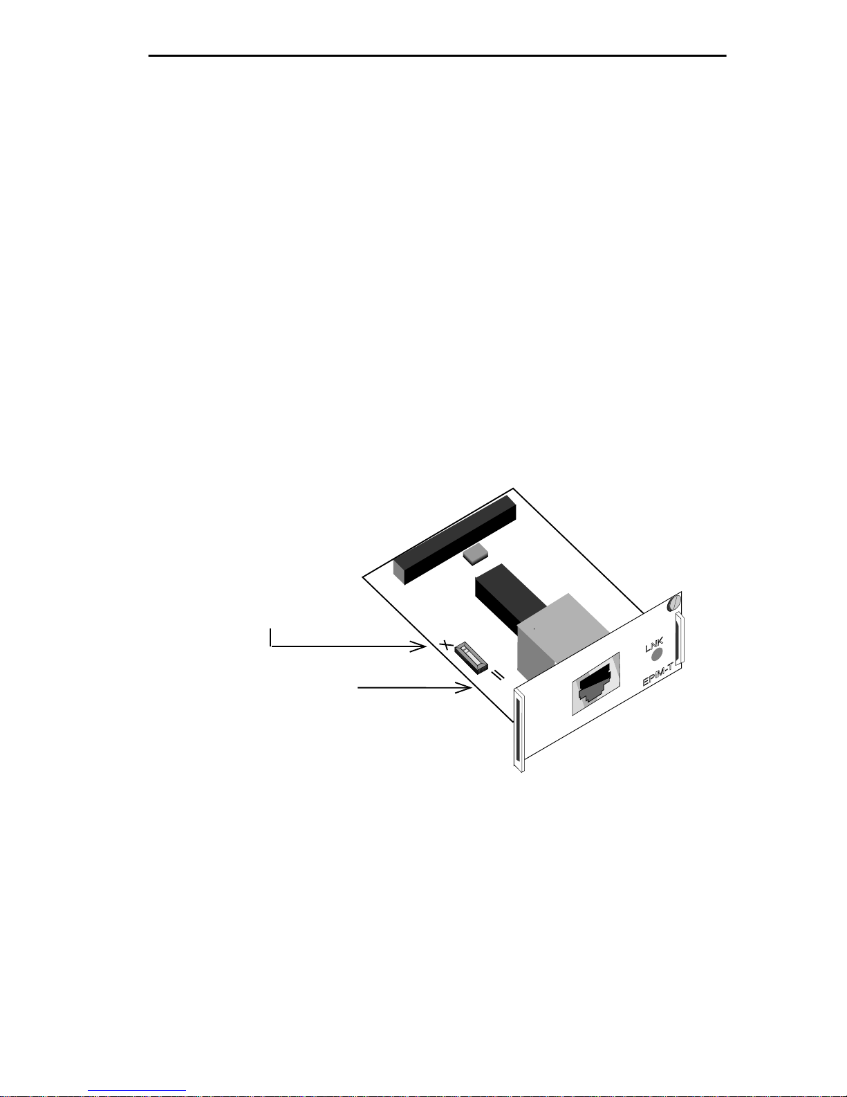
EPIM SPECIFICATIONS
A.2 EPIM CONNECTOR SPECIFICATIONS
The following sections outline specifications for each of the EPIM
connectors.
A.2.1 EPIM-T (10BASE-T Twisted Pair Port)
Internal Transceiver:Cabletron Systems TPT 10B ASE-T Twisted Pair
Transceiver
Type: 8 Pin RJ-45 Jack
A slide switch on the EPIM-T determines the cross over status of the
cable pairs. The switch residing on the X side indicates the pairs
internally cross over. If the switch resides on the = side, the pairs do
not internally cross over. See Fig. A-1.
Position X
(crossed over)
1. RX+
2. RX-
3. TX+
4. NC
5. NC
6. TX-
7. NC
8. NC
Position =
(not crossed over)
1. TX+
2. TX-
3. RX+
4. NC
Figure A-1. Crossover Switch on the EPIM-T
5. NC
6. RX-
7. NC
8. NC
Page A-7
Page 78
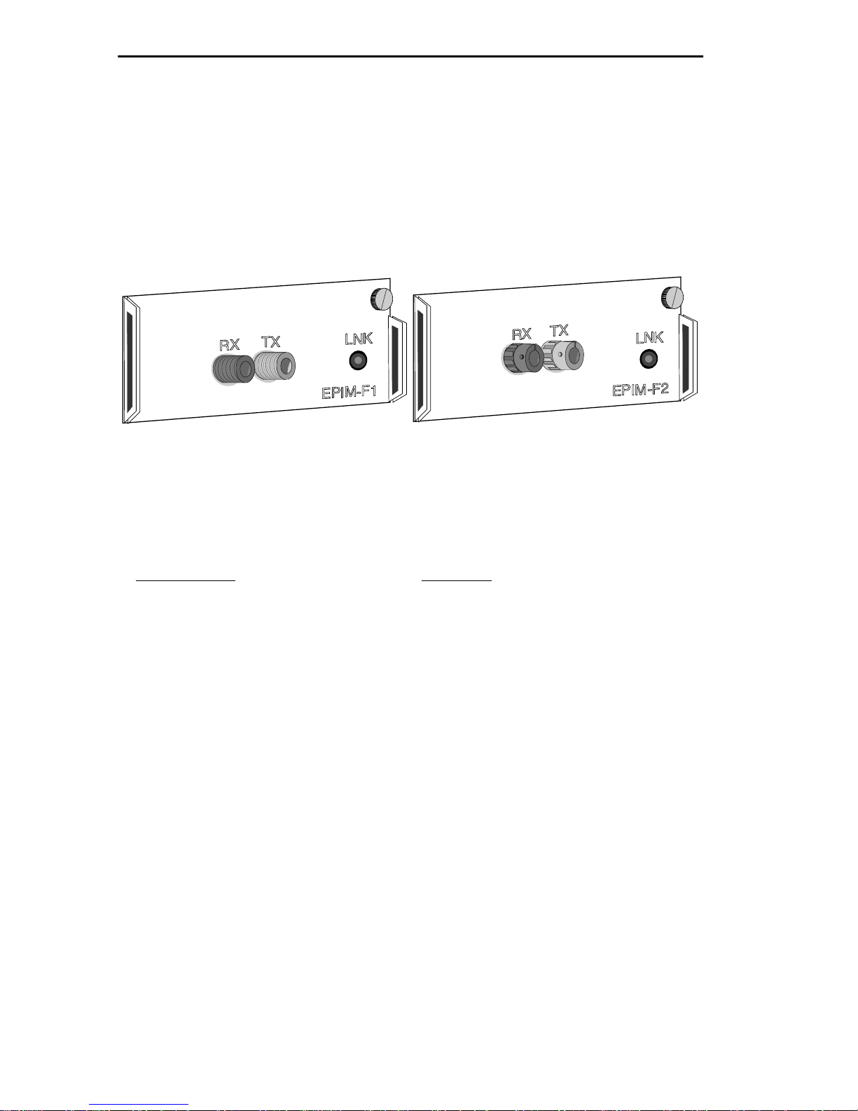
EPIM SPECIFICATIONS
A.2.2 EPIM-F1 and EPIM-F2 (Multimode Fiber Optic Ports)
Internal Transceiver: Cabletron Systems FOT-F™ Fiber Optic
Transceiver
Type:
EPIM-F1: SMA fiber optic ports
EPIM-F2: ST fiber optic ports
Figure A-2. EPIM-F1 and EPIM-F2
P
arameter Typical
Receive Sensitivity: -29.5 dBm
Max Receive Power: -8.2 dBm
Transmitter Power Into –
50/125 µm fiber: -13.0 dBm
62.5/125 µm fiber: -10.0 dBm
100/140 µm fiber: -7.0 dBm
Bit Error Rate: Better than 10
-10
Note: The above transmitter power and receive sensitivity levels
represent Peak Power Levels after optical overshoot. You must use a
Peak Power Meter to correctly compare the above values to those you
measure on any particular port. If you measure Power Levels with an
Average Power Meter, you must subtract 3 dBm from the measurement
to correctly compare measured values to the above values
(e.g., -29.5 dBm peak = -32.5 dBm average).
Page A-8
Page 79
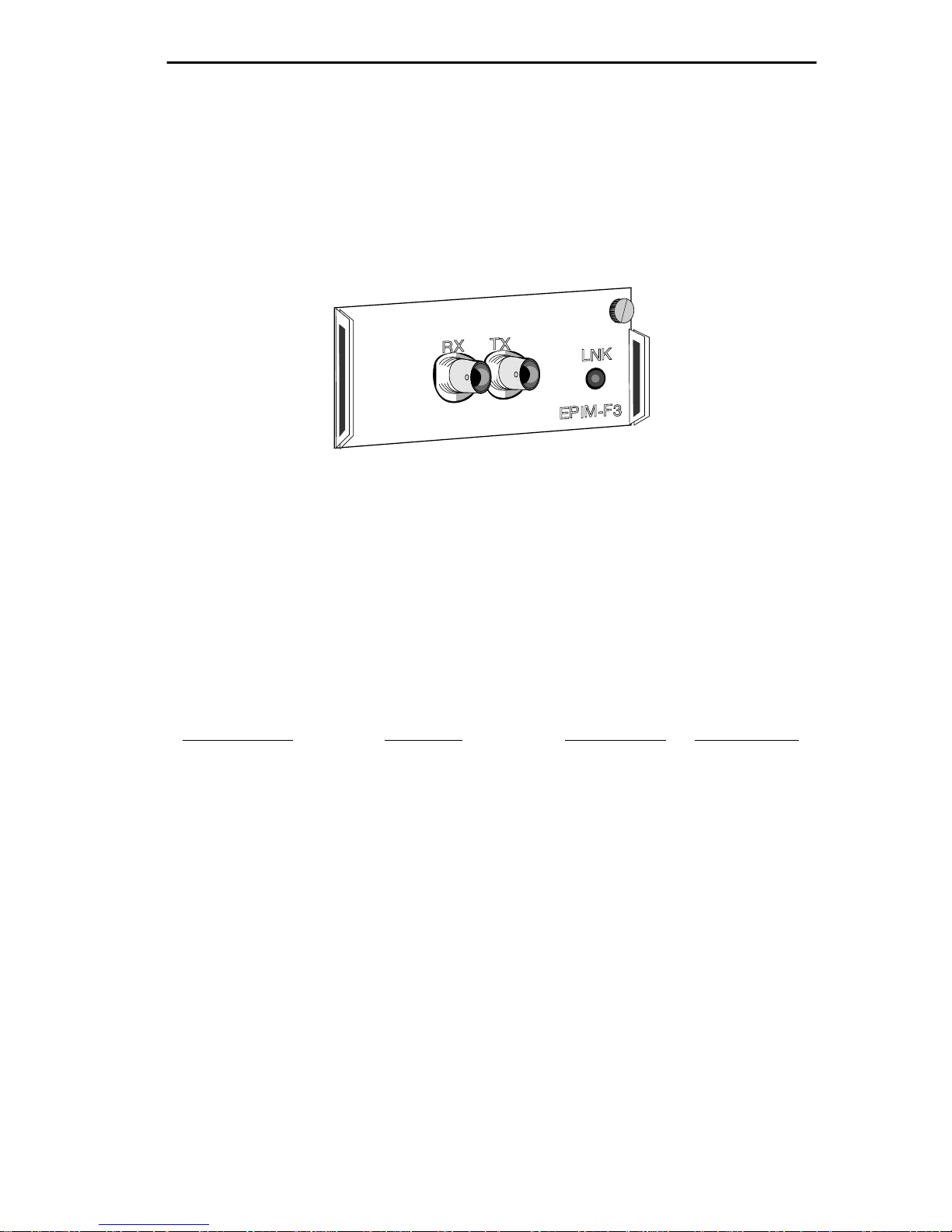
EPIM SPECIFICATIONS
A.2.3 EPIM-F3 (Single Mode Fiber Optic Port)
Internal Transceiver:Cabletron Systems FOT-F3™ Fiber Optic
Transceiver
Type: ST fiber optic ports
Figure A-3. EPIM-F3
Note: Transmitter power is inversely proportional to temperature rise.
Use the Output Power Coefficient to calculate increased or decreased
power output for your operating environment. For example, typical
power output at 25C equals -16.4 dBm. For a 4C temperature increase,
multiply the typical coefficient (-0.15 dBm) by four, and add the result
to typical output power (4 x -0.15 dBm + -16.4 dBm = -17.0 dBm).
P
arameter Typical Minimum Maximum
Transmitter Peak
Wave Length: 1300 nm 1270 nm 1330 nm
Spectral Width: 60 nm — 100 nm
Rise Time: 3.0 ns 2.7 ns 5.0 ns
Fall Time: 2.5 ns 2.2 ns 5.0 ns
Duty Cycle: 50.1% 49.6% 50.7%
Page A-9
Page 80

EPIM SPECIFICATIONS
Parameter Typical
TX Power: -15.1 dBm
TX Budget: 14.4 dBm
RX Sensitivity: -29.5 dBm
MAX Receive
-6.99 dBm
Power:
Bit Error Rate: Better than 10
-10
Note: The above transmitter power levels and receive sensitivity levels
represent Peak Power Levels after optical overshoot. You must use a
Peak Power Meter to correctly compare the above values to those you
measure on any particular port. If you measure Power Levels with an
Average Power Meter, you must subtract 3 dBm from the measurement
to correctly compare those measured values to the values listed above
(e.g., -29.5 dBm peak = -32.5 dBm average).
Page A-10
Page 81
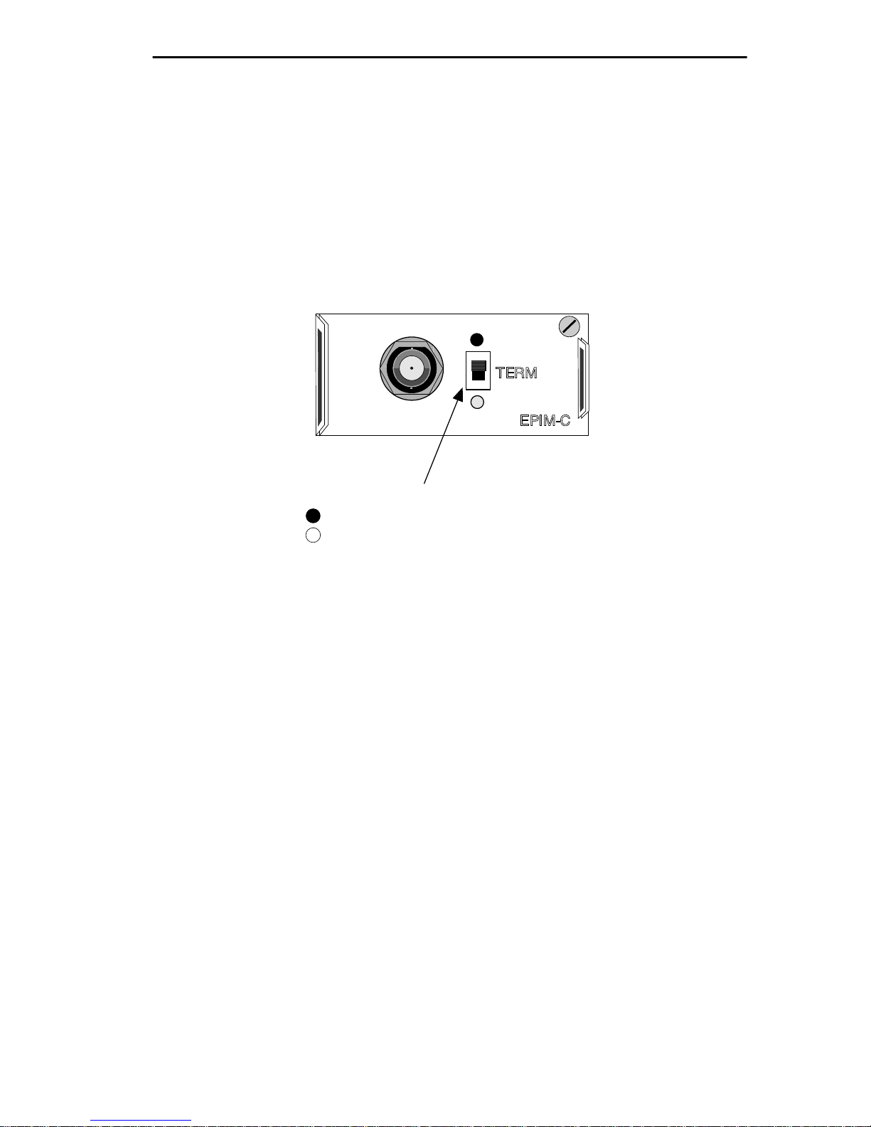
EPIM SPECIFICATIONS
A.2.4 EPIM-C (BNC Port)
Internal
Transceiver: Cabletron Systems TMS-3™ Transceiver
Type: BNC receptacle, with gold center contact, for
use with BNC type tee-connectors and RG-58
thin-net cable.
Internal Termination Switch
= On (internally terminated)
= Off (need external termination)
Figure A-4. EPIM-C (with BNC Port)
Termination: Using the switch to the side of the port, you can
internally terminate the port on the module via a
built-in 50 ohm terminator. This eliminates the
need to connect the port to a tee-connector and
terminator.
Grounding: For safety, connect only one end of a thin-net
segment to earth ground. Do not connect the
BNC port of an EPIM-C to earth ground.
Warning: Connecting a thin-net segment to earth ground at more than
one point could produce dangerous ground currents.
Page A-11
Page 82
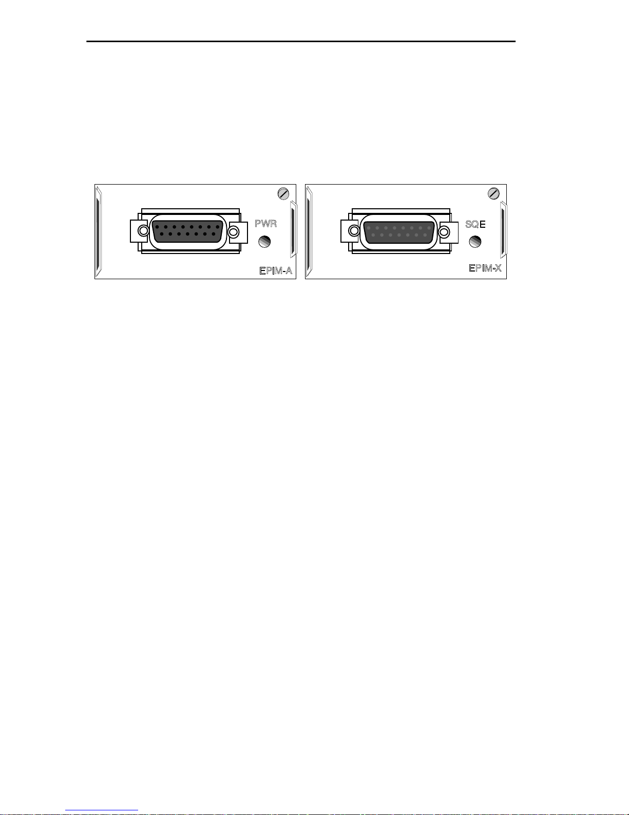
EPIM SPECIFICATIONS
A.2.5 EPIM-A and EPIM-X (AUI Ports)
Interface Connector: DB-15 Port (female connector for EPIM-A,
male connector for EPIM-X).
Type: 15 position D type receptacle
Figure A-5. EPIM-A and EPIM-X (AUI Ports)
Pin 1 Logic Ref. Pin 9 Collision -
2 Collision + 10 Transmit 3 Transmit + 11 Logic Ref.
4 Logic Ref. 12 Receive 5 Receive + 13 Power (+12 Vdc)
6 Power Return 14 Logic Ref.
7 No Connection 15 No Connection
8 Logic Ref.
Connector Shell: Protective Ground
A.3 CONNECTING AN EPIM TO THE ETHERNET NETWORK
The procedure for connecting Ethernet segments to the unit vary
depending on the media type and ports you connect. Refer to the
following list and perform the procedure described in the subsections
that apply:
• EPIM-A A.3.1
• EPIM-T A.3.2
• EPIM-F1, F2, F3 A.3.3
• EPIM-C A.3.4
• EPIM-X A.3.5
Page A-12
Page 83
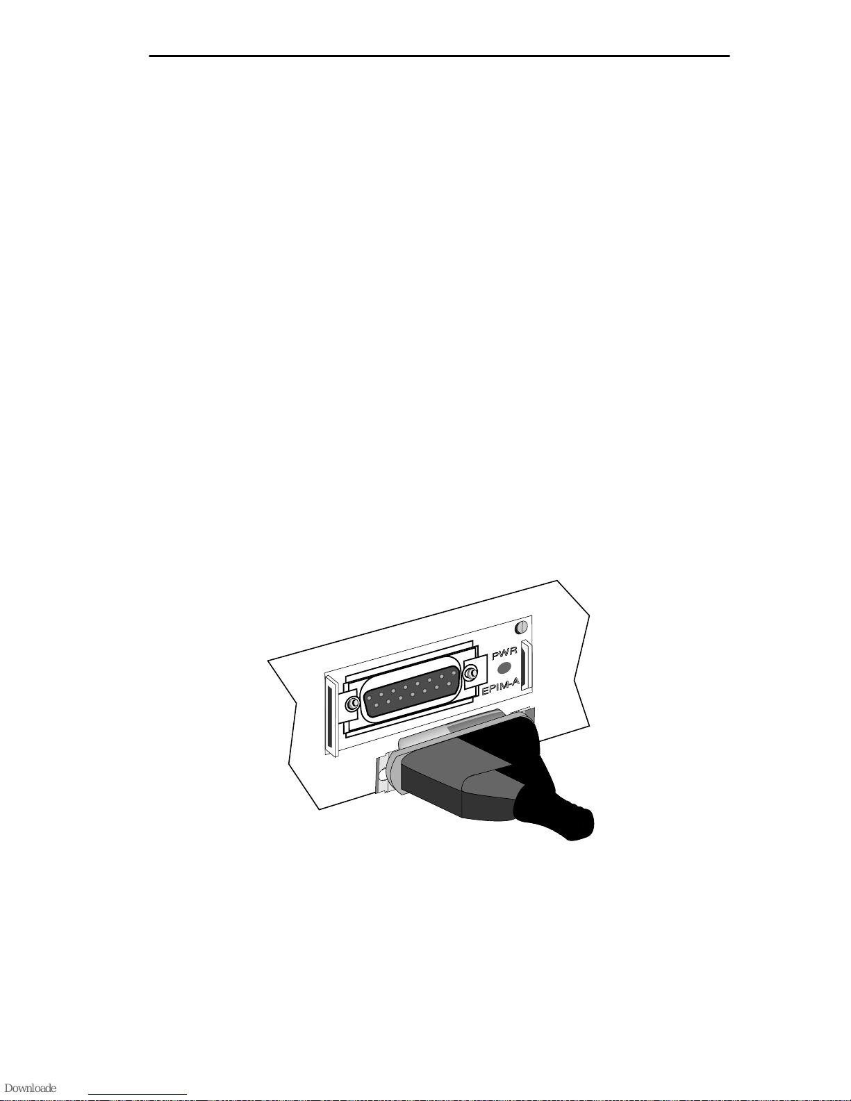
EPIM SPECIFICATIONS
A.3.1 Connecting an AUI Cable to an EPIM-A
Caution: Ensure that the external transceiver to which the ETWMIM
will be connected does not have the signal quality error (SQE or
“heartbeat”) test function enabled. The ETWMIM will not operate if the
transceiver has the SQE test function enabled, and the network will be
unusable. Refer to the applicable transceiver manual.
To connect an EPIM-A to an external network segment:
1. Attach an external transceiver to the network segment that will be
connected to the AUI port. Refer to the applicable transceiver
manual.
2. Attach an AUI cable, no longer than 50 meters in length, to the
transceiver connected to the network in step 1.
3. Connect the AUI cable to the AUI port located on the EPIM-A. See
Figure A-6.
4. Lock the AUI connector into place using the connector slide latch.
5. Check that the PWR LED on the EPIM-A is on. If the LED is not
on, contact Cabletron Systems Technical Support.
Figure A-6. The EPIM-A
Page A-13
Page 84
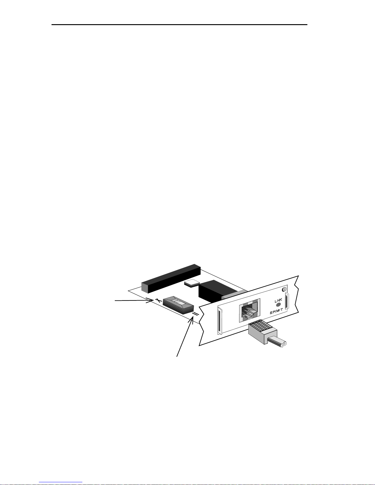
EPIM SPECIFICATIONS
6. If the PWR LED is on with the AUI cable disconnected, continue
with the following checks:
a. Check the AUI connections for proper pinouts. The pinouts for
the transceiver connection are listed in this appendix.
b. Check the cable for continuity.
c. Reconnect the AUI cable to the ETWMIM and the device.
If the LED is still not on after reconnecting the segment, contact
Cabletron Systems Technical Support.
A.3.2 Connecting an Unshielded Twisted Pair Segment to an
EPIM-T
Before connecting a segment to the EPIM-T, check each end of the
segment to determine if the wires have been crossed-over for the
proper connection. If the wires do not cross over, use the switc h on the
EPIM-T to internally cross over the RJ45 port. Refer to Figure A-7 to
properly set the EPIM-T crossover switch.
Position X
(crossed over)
1. RX+
2. RX-
3. TX+
4. NC
5. NC
6. TX-
7. NC
8. NC
Position =
(not crossed over)
Figure A-7. EPIM-T Crossover Switch
Page A-14
1. TX+
2. TX-
3. RX+
4. NC
5. NC
6. RX-
7. NC
8. NC
Page 85

EPIM SPECIFICATIONS
To connect an EPIM-T to a Twisted Pair Segment:
1. Connect the twisted pair segment to the module by inserting the
RJ45 connector on the twisted pair segment into the RJ45 port on
the module. See Figure A-7.
2. Check that the EPIM’s LNK LED is on. If the LED is not on,
perform each of the following steps until it is:
a. Check that the 10B ASE-T device at the other end of the twisted
pair segment is powered up.
b. Verify that the RJ45 connector on the twisted pair segment has
the proper pinouts.
c. Check the cable for continuity.
d. Check that the twisted pair connection meets dB loss and cable
specifications outlined in Twisted Pair Network Requirements.
e. Check that the crossover switch is in the correct position.
If a link still has not been established, contact Cabletron Systems
Technical Support.
A.3.3 Connecting a Fiber Optic Link Segment to an EPIM-F1,
EPIM-F2, or EPIM-F3
When connecting a fiber optic link segment to an EPIM-F1, F2, or F3
keep the following in mind:
• If you are connecting a fiber optic link segment with SMA 906
connectors to an EPIM-F1 with SMA ports, ensure that half
alignment sleeves are in place on each connector. A full
alignment sleeve will damage the receive port. SMA 905
connectors do not need alignment sleeves.
• If you are connecting a fiber optic link segment with ST
connectors to an EPIM-F2/F3 with ST ports, keep in mind that
ST connectors attach to ST ports much like BNC connectors
attach to BNC ports.
Page A-15
Page 86

EPIM SPECIFICATIONS
Inert the connector into the port with the alignment key on the
connector inserted into the alignment slot on the port. The
connector is then turned to lock it down.
• The physical communication link consists of two strands of
fiber optic cabling: the Transmit (TX) and the Receive (RX). The
Transmit strand from the applicable port on the module will be
connected to the Receive port of a fiber optic Ethernet device at
the other end of the segment. F or example , TX of the applicable
port on the module will go to RX of the other fiber optic device.
The Receive strand of the applicable port on the module will be
connected to the Transmit port of the fiber optic Ethernet
device. For example, RX of the applicable port on the module
will go to TX of the other fiber optic device . W e recommend that
you label the fiber optic cable to indicate which fiber is Receive
and which is Transmit. When you buy fiber optic cable from
Cabletron Systems, it is labeled so that: at one end of the cable,
one fiber is labeled 1, and the other fiber is labeled 2. This
pattern is repeated at the other end of the cable. If you did not
purchase your cable from Cabletron Systems, be sure you label
your cable as described above.
Caution: Do not touch the ends of the fiber optic strands, and do not let
the ends come in contact with dust, dirt, or other contaminants.
Contamination of the ends can cause problems in data transmissions. If
the ends become contaminated, clean them with alcohol using a soft,
clean, lint free cloth.
To connect a fiber optic link segment to an EPIM-F1, EPIM-F2, or an
EPIM-F3:
1. Remove the protective plastic covers from the fiber optic ports on
the applicable port on the module and from the ends of the
connectors on each fiber strand.
2. Attach the fiber labeled 1 to the applicable receive port, labeled RX,
on the module. See Figure A-8.
Page A-16
Page 87
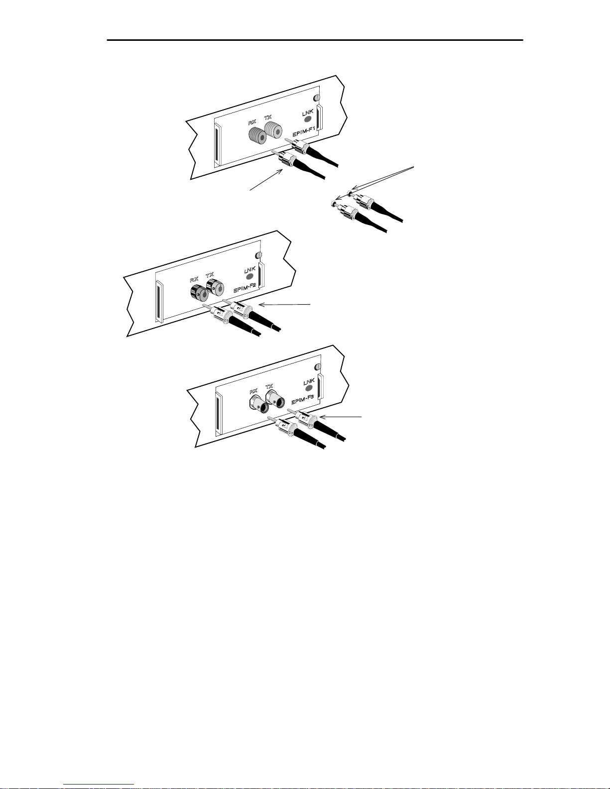
F2
EPIM SPECIFICATIONS
F1
SMA 906 Connectors w/
Half Alignment Sleeves
SMA 905 Connectors
ST Connectors
F3
ST Connectors
Figure A-8. The EPIM-F1, EPIM-F2 and EPIM-F3
3. Attach the fiber labeled 2 to the applicable transmit port labeled
TX, on the module.
4. At the other end of the fiber optic cable, attach the fiber labeled 1
to the transmit port of the device.
5. Attach the fiber labeled 2 to the receive port.
6. Check that the EPIM’s LNK LED is on. If the LED is not on,
perform the following steps until it is:
a. Check that the power is turned on for the device at the other
end of the link.
Page A-17
Page 88

EPIM SPECIFICATIONS
b. Verify that the fiber strands are properly “crossed over”
between the applicable port on the module and the fiber optic
device at the other end of the fiber optic link segment.
c. Verify that the fiber connection meets the dB loss specifications
outlined in Fiber Optic Network Requirements.
If a link still has not been established, contact Cabletron Systems
Technical Support.
A.3.4 Connecting a Thin-Net Segment to an EPIM-C
To connect a thin-net segment to an EPIM-C:
1. Set the Internal Termination Switch, located to the right of the port
and labeled TERM to:
• The on position (•) if the thin-net segment connected directly to
the port will be internally terminated at the port.
• The off position (o) if the thin-net segment will not be
terminated at the port or externally terminated.
2. If the Internal Termination switch is in the On position, connect
the thin-net segment directly to the BNC port as shown in
Figure A-9.
3. If the Internal Termination switch is in the Off position:
a. Attach a BNC tee-connector to the BNC port on the module.
b. Attach the thin-net segment to one of the female connectors on
the tee-connector.
Page A-18
Page 89
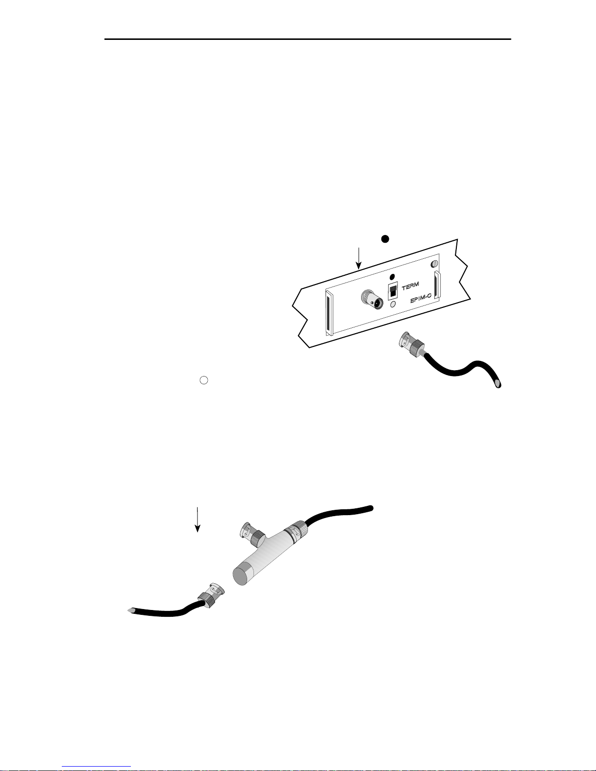
EPIM SPECIFICATIONS
Note: You must terminate each segment attached to the
tee-connector. If you do not attach a segment to one of the female
connections on the tee-connector, then a terminator must be placed
on that connection.
c. Attach another thin-coax segment or a terminator to the other
female connector on the tee-connector.
Attach thin-net segment directly to BNC
connector when internal termination
switch is set to ON ( ).
When internal termination switch
is set to OFF ( ):
Connect BNC tee-connector to port.
Attach a terminator or terminated
thin-net segment to one female
connector of tee-connector.
Connect a terminated thin-net
segment to other female connector
of tee-connector.
Figure A-9. The EPIM-C
Page A-19
Page 90
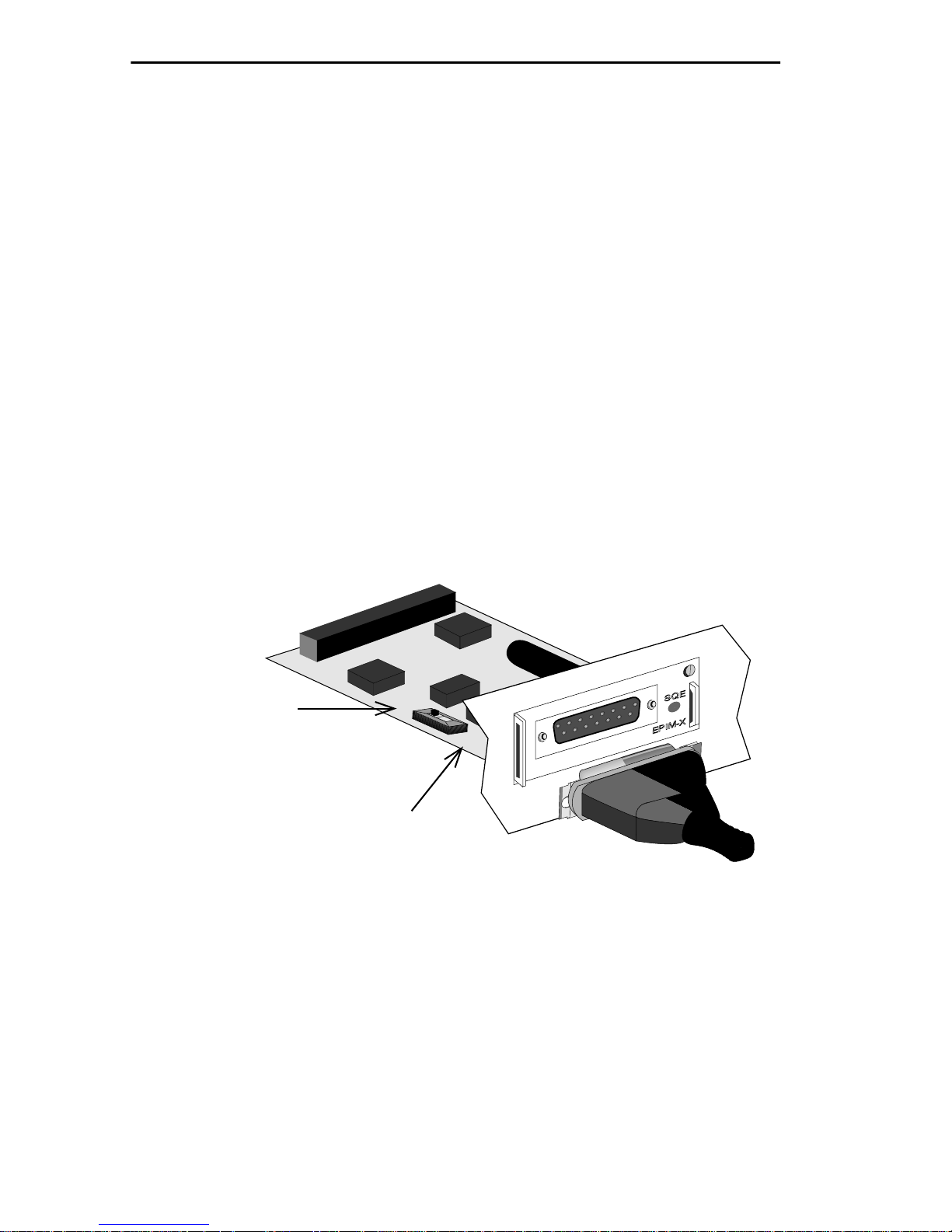
EPIM SPECIFICATIONS
A.3.5 Connecting an AUI Cable to an EPIM-X
Caution: The signal quality error (SQE) switch remains in the OFF
position for most network connections. However, some Data Terminal
Equipment (DTE) requires SQE. Refer to your DTE manual for SQE
requirement information.
To connect an EPIM-X to a device not requiring SQE:
1. Check that the SQE LED on the EPIM-X is off. If the SQE LED is
on, check the position of the SQE switch.
Note: If the SQE light remains on, even though the SQE switch is
in the OFF position, contact Cabletron Technical Support.
2. Attach one end of an AUI cable, no longer than 50 meters in length,
to the port located on the EPIM-X (Figure A-10) and the other end
to the intended node.
ON Position
(Toward Back
of EPIM)
OFF Position
(Toward Front
of EPIM)
ON
OFF
Figure A-10. The EPIM-X
Page A-20
Page 91

APPENDIX B
DOWNLOADING AN IMAGE FILE
This appendix provides instructions for downloading an image file to
the ETWMIM by setting specific MIB OID strings. To set OID strings,
you can use the SNMP Tools screen described in Chapter 5.6 of this
manual or any MIB walking tool. Refer to specific MIB walking tool
documentation for instructions on how to set MIB OID strings.
Note: You can also download an image file using various remote
management packages such as Cabletron’s Remote LANVIEW®/
Windows. Refer to specific package documentation for image file
download procedures.
The ETWMIM supports the following Download applications:
• Standard Local Download - the ETWMIM automatically
disables management while you download the new firmware
image.
• Remote Runtime Download - the ETWMIM continues to
operate without interruption while you download the new
firmware image. The ETWMIM stores the new image in Flash
memory. It continues to operate with the old firmware image
executing in processor memory until you reset the ETWMIM.
Page B-1
Page 92

DOWNLOADING AN IMAGE FILE
B.1 GETTING STARTED
Cabletron ships two versions of the same firmware image file with
each upgrade kit. The first file, suffixed with .hex (after it has been
decompressed from a .zip) is for Standard Local Downloading. The
second file, suffixed with .fls (after it has been decompressed from a
.zip) is for Remote Runtime Downloading.
Before you can download the image to a device, you must:
• load the image file onto your network rarp server
Note: For information on how to setup a workstation as a rarp
server, refer to your specific workstation documentation and the
guidelines outlined in this instruction guide.
• decompress the image file.
Note: For your convenience, Cabletron includes the PKUNZIP
utility for easy decompression of the “zipped” file. If you are
using a UNIX workstation as a rarp server, and you do not have
a decompression utility that recognizes the PKZIP format, you
can obtain a copy of a UNIX decompression utility or the image
file from the Cabletron Systems FTP server. Contact Cabletron
Technical Support for details.
Page B-2
Page 93

DOWNLOADING AN IMAGE FILE
B.2 SETTING UP A UNIX WORKSTATION AS A RARP
SERVER
Due to variations between UNIX systems, and individual
configurations, this section provides only GUIDELINES for
configuring a UNIX workstation to perform an image file download.
The instructions include command examples, where appropriate. Bold
lettering in examples indicates operator entry.
Caution: If unsure how to properly configure your UNIX workstation
using these guidelines, contact your Systems Administrator.
Before you start:
• Editing ethers or hosts files requires Root/Superuser access.
• Downloading an image file requires setting up your UNIX
workstation as a rarp server.
To set up a UNIX workstation:
1. Edit the /etc/ethers file by adding the ETWMIM Ethernet address,
followed by a unique name
(e.g., 00:00:1d:12:12:ce ETW).
Note: Colons replace dashes in the ethernet address.
2. Edit the /etc/hosts file by adding the ETWMIM IP address and
follow it with the same unique name you used in step #1 (e.g.,
132.177.118.24 ETW).
3. If you already have a /tftpboot directory, confirm the rarp setup of
your workstation as follows:
Request a process status and grep for rarpd (e.g., unix% ps -aux |
grep rarpd).
Page B-3
Page 94

DOWNLOADING AN IMAGE FILE
The following information represents a typical output:
user 161 7.7 1.2 32 184 p3 S 12:00 grep rarpd
root 87 0.0 0.9 48 136 ? S 11:05 rarpd -a
root 88 0.0 0.0 24 0 ? IW 11:05 rarpd -a
The term rarpd -a, located at the end of the root string, indicates rarp
is active. If rarp is NOT running, only the grep process appears.
4. If you do NOT have a /tftpboot directory, then you must create one
(e.g., unix% mkdir tftpboot), and start the rarp daemon (e.g.,
unix% rarpd -a).
5. Ensure that the /tftpboot directory is not owned (e.g., unix%
chown nobody tftpboot).
6. Store the hex image file in the /tftpboot directory as etw.hex.
Note: This step requires decompression of the zipped image file. If you
do not have a UNIX unzip utility, access to a PC with pkunzip, or a way
to FTP the decompressed image to your UNIX workstation, contact
Cabletron Technical Support.
7. Edit the /etc/inetd.conf file by removing anything prior to the
tftpboot daemon (e.g., the # sign) that comments-out the line.
8. Kill the inetd process (e.g., unix% kill -HUP ‘process ID
number’), and then restart the process
(e.g., unix% inetd), to enable the revised inetd.conf file.
Note: You must request a process status and grep for inetd to obtain the
process ID number (see step 3 above).
Page B-4
Page 95

DOWNLOADING AN IMAGE FILE
B.3 STANDARD LOCAL DOWNLOAD
Table B-1 provides a step by step procedure for downloading the
firmware image file. This section provides specific MIB OIDs, their
names, and the required setting for proper image file download. Refer
to your specific MIB walking tool documentation for instructions on
how to set MIB OID strings.
The Download OIDs for Cabletron products reside in Cabletron
enterprise MIBs (group 52). The specific OIDs necessary to perform an
image file download reside in the common download group under
ctDL (Cabletron Download). The full OID string to reach this group is:
1.3.6.1.4.1.52.4.1.5.8.1
When performing the steps in Table B-1, keep the following in mind:
• You must follow the steps in order.
• Enter the IP address of the rarp server in standard dotted
decimal notation (e.g., 132.177.118.24).
• Enter the FULL path to the image file in the
ctDLTFTPRequest OID, including the name of the image file
(e.g., c:\tftpboot\etw.hex).
Table B-1. Standard Download Procedure
Step
(1). ctDLForceOnBoot 1.3.6.1.4.1.52.4.1.5.8.1.1.0 integer 1
(2). ctDLCommitRAMToFlash 1.3.6.1.4.1.52.4.1.5.8.1.2.0 integer 1
(3). ctDLTFTPRequestHost 1.3.6.1.4.1.52.4.1.5.8.1.4.0 IP
(4). ctDLTFTPRequest 1.3.6.1.4.1.52.4.1.5.8.1.5.0 string
(5). ctDLInitiateColdBoot 1.3.6.1.4.1.52.4.1.5.8.1.3.0 integer 1
OID Name OID Number Data
Type
address
(ASCII)
Enter the IP address of the
rarp server.
Enter the path to the image
file.
SNMP
OID Data
Page B-5
Page 96

DOWNLOADING AN IMAGE FILE
B.4 REMOTE RUNTIME DOWNLOAD
Warning: If the Runtime Download is interrupted, the Firmware
Image in Flash memory will be erased. The ETWMIM will continue to
operate until it is either Reset or Powered OFF and ON. After either of
these events, the ETWMIM can Download a Firmware Image from a
BootP server ONLY! The process of configuring a BootP Server is
discussed at length in Cabletron’s “Remote LANVIEW/Windows
Network Control Management User’s Guide” (Chapter 10). Although
Runtime Download is a powerful network operations & firmware
management feature, careful consideration should be given to both the
timing (best when network usage is lowest) and network stability
(especially Downloads over a WAN link) at the time of the planned
Download.
Table B-2 provides a step by step procedure for downloading the
firmware image file. This section provides specific MIB OIDs, their
names, and the required setting for proper image file download. Refer
to your specific MIB walking tool documentation for instructions on
how to set MIB OID strings.
The Download OIDs for Cabletron products reside in Cabletron
enterprise MIBs (group 52). The specific OIDs necessary to perform an
image file download reside in the common download group under
ctDL (Cabletron Download). The full OID string to reach this group is:
1.3.6.1.4.1.52.4.1.5.8.1
When performing the steps in Table B-2 keep the following in mind:
• You must follow the steps in order.
• Enter the IP address of the rarp server in standard dotted
decimal notation (e.g., 132.177.118.24).
• Enter the FULL path to the image file in the
ctDLTFTPRequest OID, including the name of the image file
(e.g., c:\tftpboot\etw.fls).
Page B-6
Page 97

DOWNLOADING AN IMAGE FILE
Table B-2. Runtime Download Procedure
Step OID Name OID Number Data
Type
(1). ctDLTFTPRequestHost 1.3.6.1.4.1.52.4.1.5.8.1.4.0 IP
address
(2). ctDLTFTPRequest 1.3.6.1.4.1.52.4.1.5.8.1.5.0 string
(ASCII)
(3). ctDLOnLineDownload 1.3.6.1.4.1.52.4.1.5.8.1.16.0 integer 1 = Default setting (normal
(4) ctDLOperStatus
(This OID monitors the
progress of the Runtime
Download.)
If you selected forceDownLoadReset at Step 3, then DO NOT CONTINUE, you have completed all
necessary settings.
1.3.6.4.1.52.4.1.5.8.1.17.0 Integer 2 = Indicates that a TFTP
SNMP OID Data
Enter the IP address of the
rarp server.
Enter the path to
the image file.
operation).
2 = forceDownLoad. The
new image downloads to
Flash memory. The ETWMIM does not use the new
image until you press the
Reset button.
3 = forceDownLoadReset.
The new image downloads
to Flash memory. The
ETWMIM automatically
resets upon completion of
the download.
download request has been
received but has not yet
been activated.
3 = Indicates normal operation. The download started
and finished normally and
no reset was specified or a
download has not been
started.
4 = Indicates that a download is in progress.
5 = Indicates that download
was started but has terminated due to an error.
If you selected forceDownLoad at Step 3, then you can reset the ETWMIM at a later time. You can
reset the ETWMIM remotely using the ctDLInitiateColdBoot OID described at Step 5 or manually using
the Reset Button or Power Cycle.
(5). ctDLInitiateColdBoot 1.3.6.1.4.1.52.4.1.5.8.1.3.0 integer 1
Page B-7
Page 98

APPENDIX C
FCC PART 68 - USER’S INFORMATION
The following instructions are to ensure compliance with the Federal
Communications Commission (FCC) Rules, Part 68.
1. All direct connections to T1 lines must be made using standard
plugs and jacks.
2. Before connecting your unit, you must inform the local telephone
company of the following information:
Port ID REN/SOC FIC USOC
RJ48C
3. If the unit appears to be malfunctioning, it should be disconnected
from the telephone lines until you learn if your equipment or the
telephone line is the source of the trouble. If your equipment needs
repair, it should not be reconnected until it is repaired.
4. The CSU/DSU has been designed to prevent harm to the T1
network. If the telephone company finds that the equipment is
exceeding tolerable parameters, the telephone company can
temporarily disconnect service, although they will attempt to give
advance notice if possible.
5. Under the FCC Rules, no customer is authorized to repair this
equipment. This restriction applies regardless of whether the
equipment is in or out of warranty.
6. If the telephone company alters their equipment in a manner that
will affect use of this device, they must give you advance warning
so as to give you the opportunity for uninterrupted service. You will
be advised of your right to file a complaint with the FCC.
7. The attached affidavit must be completed by the installer.
Page C-1
Page 99

FCC PART 68
8. In the event of equipment malfunction, all repairs should be
performed by our Company or an authorized agent. It is the
responsibility of the users requiring service to report the need for
service to our Company or to one of our authorized agents.
Service can be obtained at Cabletron Systems’ Technical Support:
Address: Cabletron Systems, Inc.
35 Industrial Way
Rochester, NH 03867
Phone: Monday through Friday
between 8 A.M. and 8 P.M. EST
at (603) 332-9400.
CompuServe: GO CTRON from any ! prompt
Internet mail: support@ctron.com
Page C-2
Page 100

FCC PART 68
AFFIDAVIT FOR THE CONNECTION OF
CUSTOMER EQUIPMENT TO 1.544 MBPS AND/OR
SUBRATE DIGITAL SERVICES
For the work to be performed in the certified territory of
Telco’s name:
State of:
Country of:
I, , of
(Name of Authorized Representative) (Customer Name)
,
(Customer’s Address) (Telephone Number)
being duly sworn, state:
I have responsibility for the operation and maintenance of the
terminal equipment to be connected to 1.544 Mbps
and/or Subrate digital services. The terminal
equipment to be connected complies with Part 68 of the Commission’s
rules except for the encoded analog content and billing protection
specifications. With respect to encoded analog content and billing
protection:
• I attest that all operations associated with the establishment,
maintenance and adjustment of the digital CPE with respect to
encoded analog content and encoded billing information
continuously complies with Part 68 of the FCC’s Rules and
Regulations.
• The digital CPE does not transmit digital signals containing
encoded analog or billing information which is intended to be
decoded within the telecommunications network.
• The encoded analog and billing protection is factory set and is
not under the control of the customer.
Page C-3
 Loading...