

Page 1

FOT-F3
FIBER OPTIC TRANSCEIVER
USER’S MANUAL
Page 2

Page 3

NOTICE
Cabletron Systems reserves the right to make changes in specifications
and other information contained in this document without prior notice.
The reader should in all cases consult Cabletron Systems to determine
whether any such changes have been made.
The hardware, firmware, or software described in this manual is subject
to change without notice.
IN NO EVENT SHALL CABLETRON SYSTEMS BE LIABLE FOR ANY
INCIDENTAL, INDIRECT, SPECIAL, OR CONSEQUENTIAL
DAMAGES WHATSOEVER (INCLUDING BUT NOT LIMITED TO LOST
PROFITS) ARISING OUT OF OR RELATED TO THIS MANUAL OR
THE INFORMATION CONTAINED IN IT, EVEN IF CABLETRON
SYSTEMS HAS BEEN ADVISED OF, KNOWN, OR SHOULD HAVE
KNOWN, THE POSSIBILITY OF SUCH DAMAGES.
© Copyright 1996 by:
Cabletron Systems, Inc.,
P.O. Box 5005, Rochester, NH 03866-5005
All Rights Reserved
Printed in the United States of America
Part Number: 9030461-01 July 1996
LANVIEW
is a registered trademark of Cabletron Systems, Inc.
LAN-MD, FOT-F3, FOMIM-32/36/38, MMAC, NBR-220
trademarks of Cabletron Systems, Inc.
Velcro
is a registered trademark of Velcro Industries, B.V.
, and
IRM
are
Printed on Recycled Paper
FOT-F3 USER’S MANUAL i
Page 4

FCC NOTICE
This device complies with Part 15 of the FCC rules. Operation is subject
to the following two conditions: (1) this device may not cause harmful
interference, and (2) this device must accept any interference received,
including interference that may cause undesired operation.
Note:
limits for a Class A digital device, pursuant to Part 15 of the FCC rules.
These limits are designed to provide reasonable protection against
harmful interference when the equipment is operated in a commercial
environment. This equipment uses, generates, and can radiate radio
frequency energy and if not installed in accordance with the operator’s
manual, may cause harmful interference to radio communications.
Operation of this equipment in a residential area is likely to cause
interference in which case the user will be required to correct the
interference at his own expense.
Warning:
expressly approved by the party responsible for compliance could void
the user’s authority to operate the equipment.
This equipment has been tested and found to comply with the
Changes or modifications made to this device which are not
DOC NOTICE
This digital apparatus does not exceed the Class A limits for radio noise
emissions from digital apparatus set out in the Radio Interference
Regulations of the Canadian Department of Communications.
Le présent appareil numérique n’émet pas de bruits radioélectriques
dépassant les limites applicables aux appareils numériques de la class
A prescrites dans le Règlement sur le brouillage radioélectrique édicté
par le ministère des Communications du Canada.
ii FOT-F3 USER’S MANUAL
Page 5
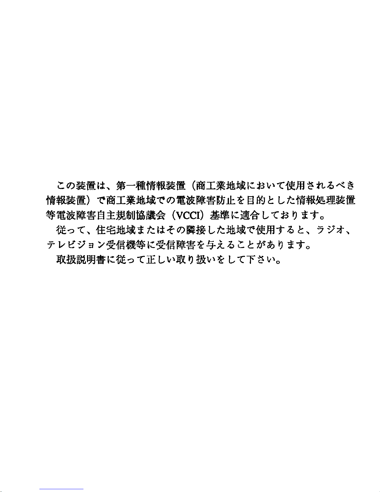
VCCI NOTICE
This equipment is in the 1st Class Category (information equipment to
be used in commercial and/or industrial areas) and conforms to the
standards set by the Voluntary Control Council for Interference by
Information Technology Equipment (VCCI) aimed at preventing radio
interference in commercial and/or industrial areas.
Consequently, when used in a residential area or in an adjacent area
thereto, radio interference may be caused to radios and TV receivers,
etc.
Read the instructions for correct handling
.
FOT-F3 USER’S MANUAL iii
Page 6

DECLARATION OF CONFORMITY
Application of Council Directive(s):
Manufacturer’s Name:
Manufacturer’ s Address:
European Representative Name:
European Representative Address:
Conformance to Directive(s)/Product Standards:
89/336/EEC
73/23/EEC
Cabletron Systems, Inc.
35 Industrial Way
PO Box 5005
Rochester, NH 03867
Mr. J. Solari
Cabletron Systems Limited
Nexus House, Newbury
Business Park
London Road, Newbury
Berkshire RG13 2PZ,
England
EC Directive 89/336/EEC
EC Directive 73/23/EEC
EN 55022
EN 50082-1
EN 60950
Equipment Type/En vironment:
Networking Equipment, for
use in a Commercial or Light
Industrial Environment.
We the undersigned, hereby declare that the equipment packaged with this notice
conform to the above directives.
Manufacturer Legal Representative in Europe
Mr. Richard Michaud Mr. J. Solari
______________________________ ________________________
Full Name Full Name
Manager of Engineering Services Managing Director - E.M.E.A.
______________________________ ________________________
Title Title
Rochester, NH, USA Newbury, Berkshire, England
______________________________ ________________________
Location Location
iv FOT-F3 USER’S MANUAL
Page 7

CONTENTS
CHAPTER 1 INTRODUCTION
1.1 USING THIS MANUAL...............................................................1-1
1.2 CONVENTIONS.........................................................................1-2
1.3 OVERVIEW OF THE FOT-F3....................................................1-2
1.3.1 Connections...............................................................1-3
1.3.2 Distance and Cable Type...........................................1-4
1.3.3 LANVIEW LEDs.........................................................1-5
1.3.4 Application..................................................................1-7
1.4 GETTING HELP.........................................................................1-9
1.5 RELATED MANUALS ..............................................................1-10
CHAPTER 2 INSTALLATION REQUIREMENTS
2.1 NETWORK DESIGN GUIDELINES ...........................................2-1
2.1.1 Fiber Optic Requirements..........................................2-1
2.1.2 AUI Cable Requirements ...........................................2-2
CHAPTER 3 INSTALLATION
3.1 UNPACKING THE FOT-F3........................................................3-1
3.2 CONNECTING THE FOT-F3 TO THE NETWORK....................3-2
3.2.1 Setting the SQE Switch..............................................3-2
3.2.3 Connecting the Fiber Optic Cable..............................3-5
3.3 SURFACE MOUNTING THE FOT-F3........................................3-8
3.4 CABLE SUPPORT INSTALLATION...........................................3-9
3.4.1 Cable Strain Relief for Surface Mounted FOT-F3......3-9
3.4.2 Cable Strain Relief for Non-Mounted FOT-F3..........3-10
FOT-F3 USER’S MANUAL v
Page 8

CONTENTS
CHAPTER 4 TESTING AND TROUBLESHOOTING
4.1 INSTALLATION CHECK-OUT ...................................................4-1
4.1.1 Testing the Fiber Optic Link Segment........................4-1
4.1.2 Testing the FOT-F3 Fiber Optic Transceiver .............4-3
4.2 USING LANVIEW.......................................................................4-4
APPENDIX A SPECIFICATIONS
A.1 FIBER OPTIC INTERFACE.................................................. A-1
A.2 AUI CONNECTOR................................................................ A-3
A.3 POWER SUPPLY ................................................................. A-3
A.4 ENVIRONMENTAL............................................................... A-4
A.5 AGENCY APPROVALS........................................................ A-4
A.6 PHYSICAL ............................................................................ A-4
vi FOT-F3 USER’S MANUAL
Page 9

CHAPTER 1
INTRODUCTION
Welcome to Cabletron Systems
Transceiver User’s Manual
installation and reference guide for the FOT-F3 transceiver.
You should have a general working knowledge of Ethernet or
IEEE 802.3 type data communications networks and their
physical layer components before installing the FOT-F3.
FOT-F3 Fiber Optic
. This manual serves as a simple
1.1 USING THIS MANUAL
You should read through this manual to gain a full understanding
of the FOT-F3 and its capabilities.
This manual is organized as follows:
Chapter 1,
FOT-F3, outlines the conventions used in this manual, provides
information on how to receive additional help, and provides a list
of related manuals.
Chapter 2,
and hardware requirements that must be met before installing
the FOT-F3.
Chapter 3,
FOT-F3, setting the SQE switch, connecting the transceiver to
the network, connecting the transceiver to an active Ethernet
device, and, if desired, mounting the transceiver with the Velcro
mounts provided with the unit.
Introduction
Installation Requirements
Installation
, discusses the capabilities of the
, contains steps for unpacking the
, contains the network
FOT-F3 USER’S MANUAL 1-1
Page 10

CHAPTER 1:
INTRODUCTION
Chapter 4,
T esting and Tr oubleshooting
, contains procedures
for verifying the proper installation of the FOT-F3. It also
describes LANVIEW LEDs and their function.
Appendix A,
Specifications
, provides the specifications for the
FOT-F3 transceiver.
1.2 CONVENTIONS
The following conventions are used in this manual:
•
•
Note
— Calls the reader’s attention to any item of
information that may be of special importance.
Caution
— Contains information essential to avoid damage
to the equipment.
1.3 OVERVIEW OF THE FOT-F3
The FOT-F3 Fiber Optic Transceiver (Fiber Optic Medium
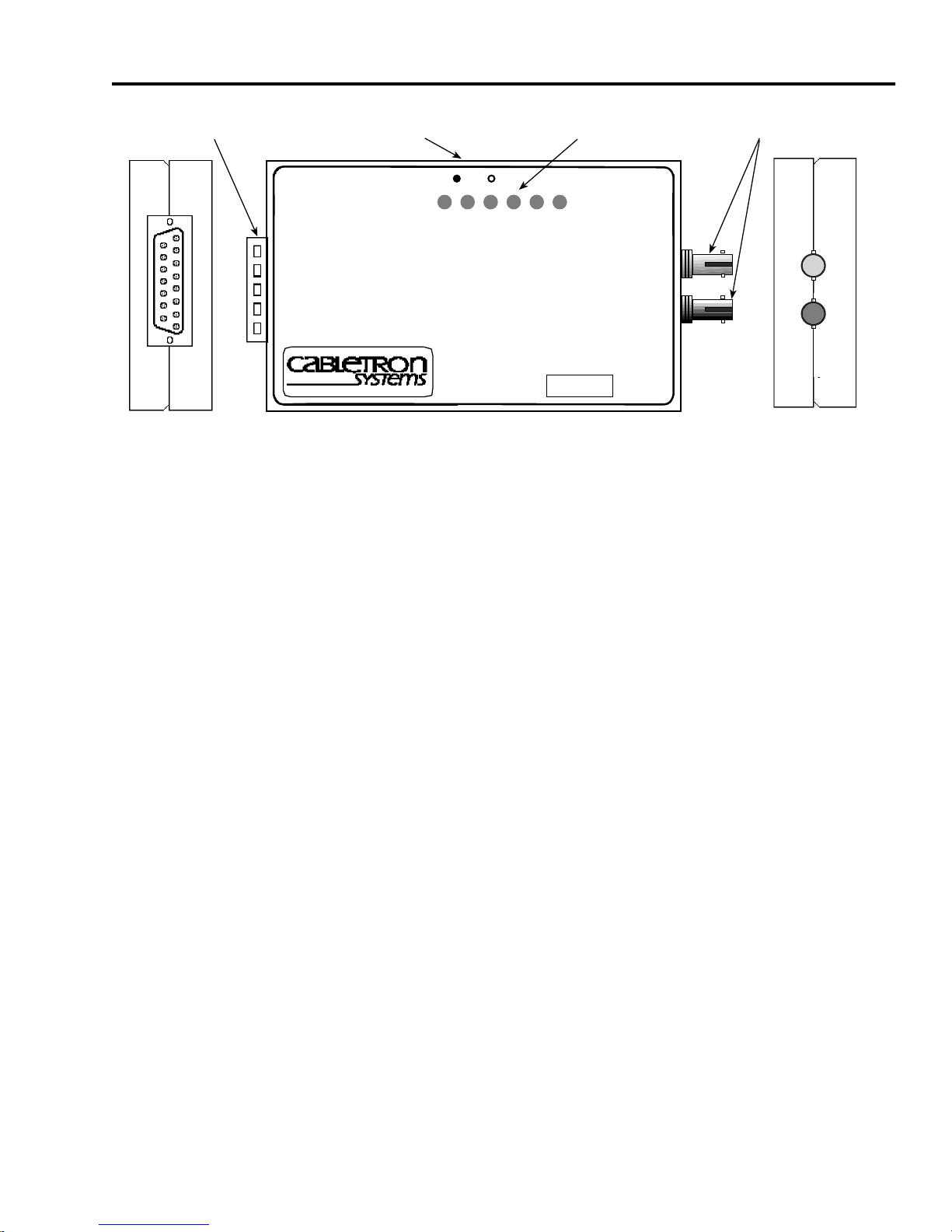
Attachment Unit or FOMAU) (Figure 1-1) is a device that allows
the connection of two Ethernet devices using single mode fiber
optic cable. The FOT-F3 uses the same signaling protocols
specified by FOIRL and is completely IEEE 802.3 compatible at
the AUI interface (the AUI port connects the transceiver to a
device or workstation via an AUI cable).
The FOT-F3 also has the Cabletron Systems LANVIEW
diagnostic system that monitors network activity and can help to
quickly diagnose physical layer problems using its LEDs.
1-2 FOT-F3 USER’S MANUAL
Page 11
OVERVIEW OF THE FOT-F3
DB15 AUI Port
End View
SQE Switch
SQE
FOT-F3
P
S
X
R
W
Q
R
802.3 COMPATIBLE SINGLE MODE
FIBER OPTIC TRANSCEIVER
with LANVIEW
®
M
E
T
Front View
C
C
L
V
N
SN
Figure 1-1 FOT-F3
LANVIEW LEDs
L
N
K
TX
RX
1300nm
ST Fiber Optic Ports
End View
0461-01
1.3.1 Connections
The FOT-F3 connects two active Ethernet devices using an AUI
cable and a fiber optic link segment. Devices such as repeaters,
multiport repeaters, multiport transceivers or host systems are
connected using fiber optic cables.
The FOT-F3 is fully compatible with IEEE 802.3 and uses the
same signaling specified in FOIRL specifications. It provides the
flexibility to connect to networks using Ethernet Version 1,
Version 2, and/or IEEE 802.3 equipment through an AUI port.
However, the FOT-F3 uses 1300 nm wave-length optical
transmitters and receivers and should be used only with
Cabletron Systems Ethernet single mode products such as the
FOMIM-36, FOMIM-32, and the FOMIM-38.
FOT-F3 USER’S MANUAL 1-3
Page 12

CHAPTER 1:
INTRODUCTION
A fiber optic cable is connected to the transceiver through ST
fiber optic ports on the FOT-F3. This provides an optical link to
connect the device to the network.
1.3.2 Distance and Cable Type
The FOT-F3 supports single mode fiber optic cable for sizes
such as 8.3/125 µm, 8.7/125 µm, 9/125 µm, and 10/125 µm.
You can also use multimode cable such as 62.5/125 µm, but
the signal distance will be much shorter.
The signal distance is dependent on the cable type and the
overall system fiber optic budget. If the system budgets and
timing constraints are met, then a distance of over five
kilometers is possible with single mode cable. However,
Cabletron Systems only supports a distance of 5 kilometers. If
using 62.5/125 multimode cable, signal distance is about 2 km.
An AUI cable, up to 50 meters long, is used to connect an
Ethernet device to the AUI port on the transceiver. The AUI
cable must meet specifications for either IEEE 802.3 or
Ethernet Version 1 or Version 2.
Signal Quality Error (SQE) Test
The FOT-F3 has a Signal Quality Error (SQE) Test Enable
Switch that allows the enabling or disabling of the SQE
(“heartbeat”) test function. The SQE test enables the FOT-F3
transceiver to generate a signal to ensure that the collision
circuit and path are operational between the FOT-F3 and the
Ethernet device attached to the AUI port of the transceiver.
1-4 FOT-F3 USER’S MANUAL
Page 13

OVERVIEW OF THE FOT-F3
The SQE test signal is generated after the FOT-F3 has
transmitted a data packet. This signal is generated only between
the FOT-F3 and the device; it is not transmitted onto the
network.
Note:
Do not enable the SQE test feature when the FOT-F3 is
attached to a repeater or Ethernet Version 1 equipment.
Otherwise, network problems (excess collisions) will result.
1.3.3 LANVIEW LEDs
The FOT-F3 incorporates Cabletron Systems LANVIEW
diagnostic and monitoring system. LANVIEW is a series of LEDs
incorporated into all Cabletron Systems products. If a problem
arises, troubleshooting of power failures, collisions, cable faults,
or many other problems can be diagnosed rapidly using these
LEDs.
The LANVIEW LEDs are shown in Figure 1-2 followed by a brief
description of each LED.
Note:
Chapter 4,
Testing and Troubleshooting,
provides more
detail about the LANVIEW LEDs and how to interpret them for
troubleshooting.
P
W
R
S
Q
E
X
M
T
R
C
V
C
L
N
L
N
K
0461-05
Figure 1-2 LANVIEW LEDs
FOT-F3 USER’S MANUAL 1-5
Page 14

CHAPTER 1:
INTRODUCTION
PWR (Power)
When on, this green LED indicates that the FOT-F3 is receiving
power.
SQE (Signal Quality Error) Test Function
When on, this yellow LED indicates that SQE is enabled.
XMT (Transmit)
This green LED flashes to indicate that the FOT-F3 is
transmitting frames onto the network.
RCV (Receive)
This yellow LED flashes to indicate that the FOT-F3 is receiving
frames from the network.
CLN (Collision)
This red LED flashes to indicate that the FOT-F3 is detecting a
collision on the network.
LNK (Link OK)
When on, this green LED indicates that a link has been
established between the FOT-F3 and the device at the other end
of the fiber optic link segment.
1-6 FOT-F3 USER’S MANUAL
Page 15
OVERVIEW OF THE FOT-F3
1.3.4 Application
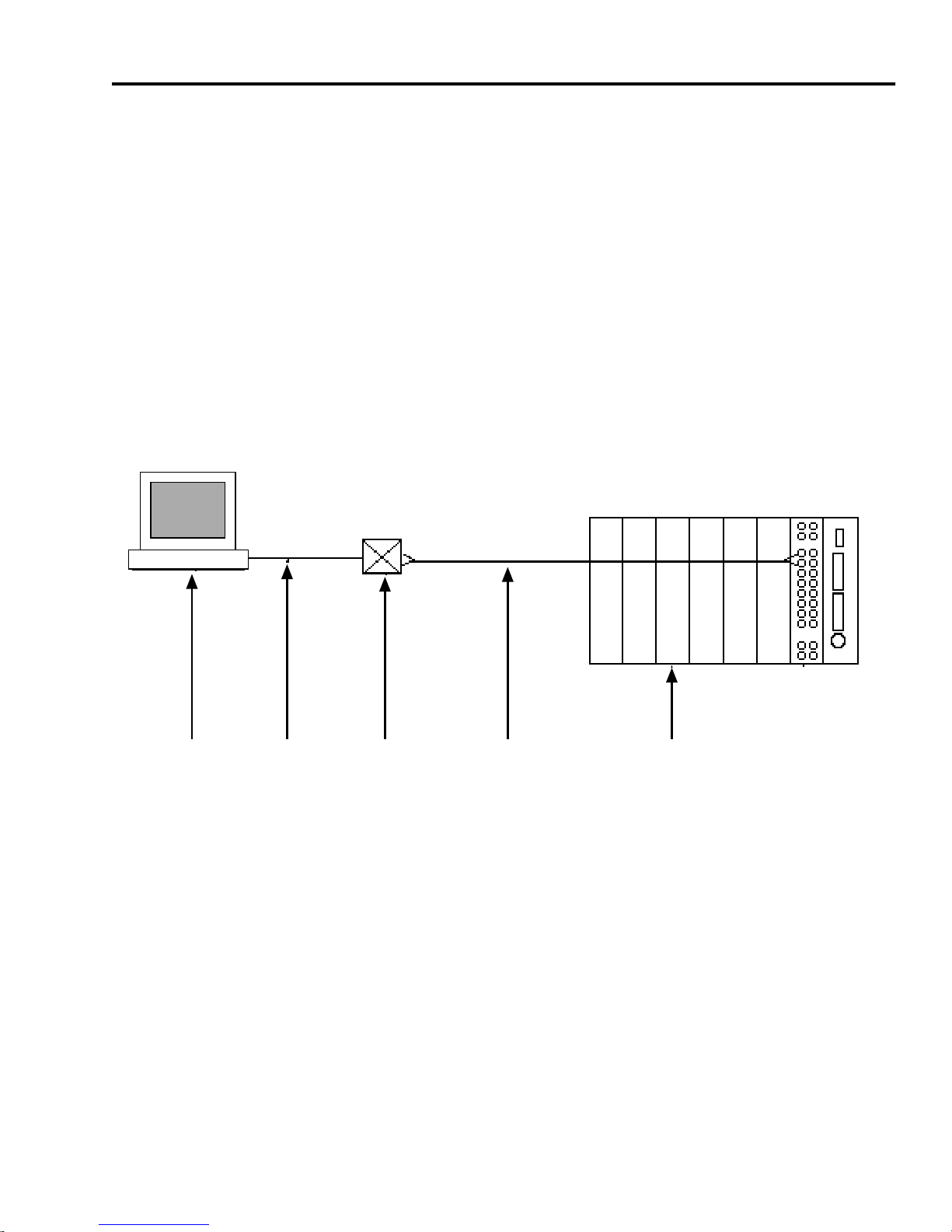
The FOT-F3 can be configured into your network in many ways.
For example, in Figure 1-3, a fiber optic link segment (4) is
attached to a Cabletron Systems Multi Media Access Center
(MMAC) (5) with a FOMIM-32/36/38. The MMAC serves as an
intelligent repeater hub that links the fiber optic link segment to
other network segments, regardless of media type. The link
segment is attached to the FOT-F3 (3). An Ethernet device, such
as a workstation (1), is connected to the FOT-F3 through an AUI
cable (2).
1 2 3 4 5 6
1. Workstation
2. AUI Cable
3. FOT-F3
4. Fiber Optic Link
5. MMAC with a Fiber Optic MIM
0461-02
Figure 1-3 FOT-F3 Setup, Example 1
FOT-F3 USER’S MANUAL 1-7
Page 16
CHAPTER 1:
INTRODUCTION
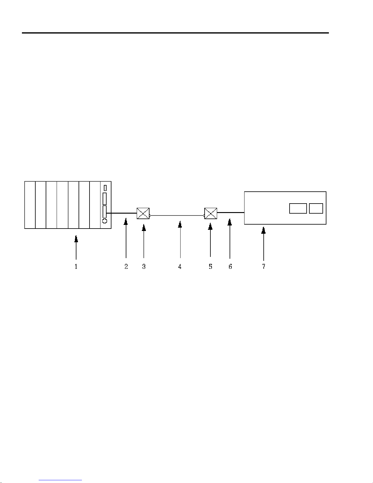
In another example, shown in Figure 1-4, a FOT-F3 (3) is
connected to an MMAC (1) by an AUI cable (2) attached to an
Intelligent Repeater Module (IRM) in the MMAC. A lengthy fiber
optic link segment (4) of up to five kilometers runs from the
FOT-F3 (3) to another FOT-F3 (5). The hardware connection is
completed via another AUI cable (6) to a Cabletron Systems
NBR-220 Ethernet Bridge (7) configured to provide an AUI
interface. Through the bridge, the host device communicates
with other devices on a larger Ethernet network attached to the
AUI port of the bridge.
1. MMAC
2. AUI Cable
3. FOT-F3
4. Fiber Optic Link
5. FOT-F3
6. AUI Cable
7. NBR-220 Bridge
0461-03
Figure 1-4 FOT-F3 Setup, Example 2
1-8 FOT-F3 USER’S MANUAL
Page 17

GETTING HELP
1.4 GETTING HELP
If you need additional support related to this device, or if you
have any questions, comments, or suggestions concerning this
manual, contact Cabletron Systems Technical Support:
By phone (603) 332-9400
Monday – Friday; 8
A.M
. – 8
P.M
.
Eastern Time
By CompuServe GO CTRON from any ! prompt
By Internet mail [email protected]
By FTP ctron.com (134.141.197.25)
Login
Password
anonymous
your email address
Before calling Cabletron Systems Technical Support, have the
following information ready:
• A description of the failure
• A description of any action(s) already taken to resolve the
problem (e.g., changing mode switches, rebooting the unit,
etc.)
• A description of your network environment (layout, cable
type, etc.)
• Network load and frame size at the time of trouble (if known)
• The serial and revision numbers of all Cabletron Systems
products in the network
FOT-F3 USER’S MANUAL 1-9
Page 18

CHAPTER 1:
INTRODUCTION
• The device history (i.e., have you returned the device
before, is this a recurring problem, etc.)
• Any previous Return Material Authorization (RMA) numbers
1.5 RELATED MANUALS
Use the manuals identified below to supplement the procedures
and other technical data provided in this manual. The
procedures contained in these manuals are referenced only.
• Cabletron Systems
User’s Manual
• Cabletron Systems
Module Installation Guide
LAN-MD Portable Ethernet Tester
FOMIM-32/36/38 Fiber Optic Interface
1-10 FOT-F3 USER’S MANUAL
Page 19

CHAPTER 2
INSTALLATION REQUIREMENTS
Before installing the FOT-F3 Fiber Optic Transceiver, all
conditions, guidelines, specifications, and requirements
included in this chapter and Appendix A must be met to ensure
satisfactory performance from the FOT-F3. Failure to follow
these guidelines may result in unsatisfactory network
performance.
2.1 NETWORK DESIGN GUIDELINES
The following design guidelines must be met when connecting
devices using the FOT-F3.
2.1.1 Fiber Optic Requirements
• The fiber optic link segments should consist of single mode
8/125 - 12/125 µm fiber optic cabling. You can also use
multimode 62.5/125 µm fiber optic cabling, but signal
distance will be much shorter (about 2 km).
• The link segment must be tested with a fiber optic
attenuation test set that is adjusted for a 1300 nm
wavelength. This test verifies if the signal loss in a cable is
within an acceptable level of 9.0 dB or less for any given
single mode fiber optic link.
FOT-F3 USER’S MANUAL 2-1
Page 20

CHAPTER 2:
INSTALLATION REQUIREMENTS
• When determining the maximum fiber optic cable length,
the fiber optic budget and total network propagation delay
should be calculated and taken into consideration before
fiber runs are incorporated into any network design. Fiber
optic budget is the combination of the optical loss due to the
fiber optic cable, in-line splices, and fiber optic connectors.
Propagation delay is the amount of time it tak es a pack et to
trav el from the sending de vice to the receiving device . If the
total one way propagation delay between any two nodes
anywhere in the network exceeds 25.6 µs, use some form
of segmentation, such as bridging or routing, to divide the
problem signal paths into smaller segments.
2.1.2 AUI Cable Requirements
• The AUI cable connecting the transceiver to a device must
be an Ethernet V ersion 1, V ersion 2, and/or IEEE 802.3 type
cable that matches the type of de vice being attached to the
AUI port.
• The AUI cable must not exceed 50 meters (164 feet) in
length. If a 28 AWG AUI cable (office AUI) is used, limit the
cable length to 16 meters (50 feet).
2-2 FOT-F3 USER’S MANUAL
Page 21

CHAPTER 3
INSTALLATION
This chapter contains instructions for unpacking the FOT-F3
Transceiver, connecting the FOT-F3 to an Ethernet device and
the network, surface mounting the transceiver (if necessary),
and cable support installation. Verify that all the requirements
listed in Chapter 2,
Appendix A,
Specifications
Installation Requirements
, are met before installing the
, and
transceiver.
3.1 UNPACKING THE FOT-F3
Before installing the FOT-F3, visually inspect the transceiver
and check the contents of the accessory package. To unpack
the transceiver:
1. Carefully remove the transceiver from the shipping box.
Save the shipping box and materials in the event the
transceiver has to be reshipped.
2. Remove the transceiver from its protective plastic bag and
set the transceiver aside.
3. Remove the accessory package from the box. It should
contain:
• One set of Velcro mounts
• Two cable mounts (for strain relief)
• Two 4-inch cable ties
FOT-F3 USER’S MANUAL 3-1
Page 22

CHAPTER 3:
INSTALLATION
If you notice any discrepancies, contact Cabletron Systems
Technical Support immediately. Refer to Chapter 1,
Getting Help
, for instructions.
3.2 CONNECTING THE FOT-F3 TO THE NETWORK
After you are sure that all the requirements listed in Chapter 2,
Installation Requirements
, and Appendix A,
Specifications
,
have been met, proceed with the installation instructions
contained in this section.
Note:
Ensure that the site where the FOT-F3 will be located will
allow the AUI cable and the fiber optic link segment to be easily
connected to the transceiver before you begin the installation
procedures.
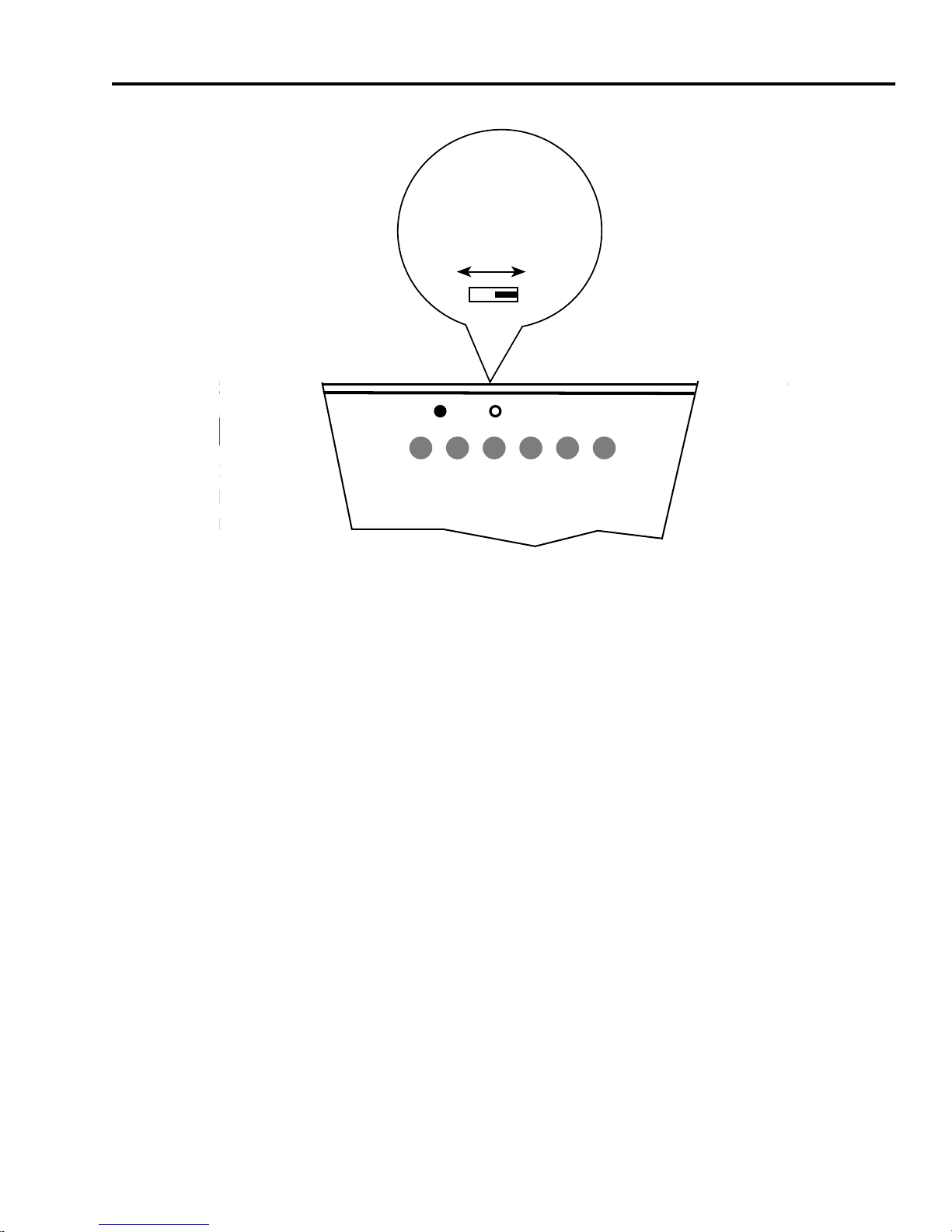
3.2.1 Setting the SQE Switch
The Signal Quality Error (SQE) Test Switch allows you to enable
or disable the SQE (“heartbeat”) test function. The SQE switch
is the two position switch on the right side of the FOT-F3, located
above the fiber optic ports (see Figure 3-1). The SQE test
function is disabled when the transceiver is shipped.
Note:
The SQE test function must be
disabled
if you are
connecting the transceiver to Ethernet Version 1 equipment or
to a repeater.
Set the SQE Switch as follows:
• To disable the SQE test function, set the s witch (Figure 3-1)
towards the optical ports to the off ( ) setting.
• To enable the SQE test function, set the s witch (Figure 3-1)
awa y from the optical ports to the on ( ) setting on the label.
3-2 FOT-F3 USER’S MANUAL
Page 23
CONNECTING THE FOT-F3 TO THE NETWORK
SQE SWITCH
T-F3
SQE
Enabled
SQE
P
S
W
Q
R
E
X
M
T
SQE
Disabled
R
C
C
L
V
N
L
N
K
Figure 3-1 SQE Switch
TX
0461-06
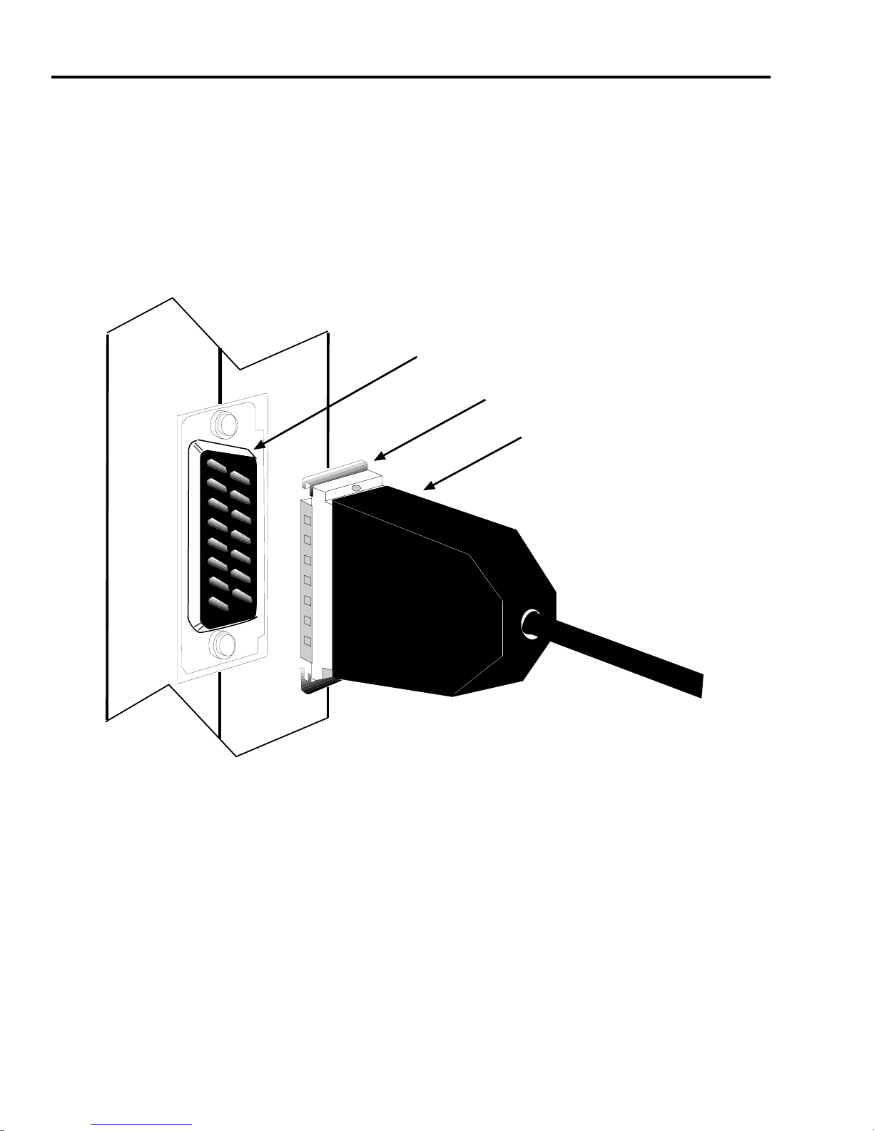
3.2.2 Connecting the AUI Cable
To connect your Ethernet device to the FOT-F3, attach an AUI
cable as follows. See Figure 3-2.
1. Attach an AUI cable to the device to which the FOT-F3 will
be connected.
FOT-F3 USER’S MANUAL 3-3
Page 24
CHAPTER 3: INSTALLATION
2. Attach the female connector on the AUI cable to the AUI
port on the FOT-F3. If the power is on for the Ethernet
device, the PWR LED should be lit, indicating the
transceiver is receiving power from the device. Also, if the
SQE test is enabled, the SQE LED should be lit.
SLIDE LATCH
AUI Port
Slide Latch
AUI Connector
AUI CONNECTOR
Figure 3-2 AUI Connection
If the PWR LED is not lit, perform the following steps:
0461-07
a. Verify that the power is turned on for the device
attached to the FOT-F3.
b. Disconnect the AUI cable from the FOT-F3.
3-4 FOT-F3 USER’S MANUAL
Page 25

CONNECTING THE FOT-F3 TO THE NETWORK
c. Disconnect the device to which the transceiver is
attached.
d. Check the AUI connections for proper pinouts. The
pinouts for the transceiver connection are listed in
Appendix A.
e. Check the cable for continuity.
f. Reconnect the AUI cable to the FOT-F3 and the
device.
3. Mov e the slide loc k on the AUI connector to secure it to the
lock posts on the port.
3.2.3 Connecting the Fiber Optic Cable
This section describes how to connect the fiber optic link
segment to the FOT-F3. Perform the following steps only after
testing the fiber optic cable to ensure that the cable has no
defects.
Note: It is recommended to label the fiber optic cable to indicate
which fiber is Receive and which is Transmit. When you buy
fiber optic cable from Cabletron Systems, at one end of the
cable, one fiber is labeled 1, and the other fiber is labeled 2. This
pattern is repeated at the other end of the cable. If you did not
purchase your cable from Cabletron Systems, then be sure you
have labeled your cable in the manner described above.
FOT-F3 USER’S MANUAL 3-5
Page 26

CHAPTER 3: INSTALLATION
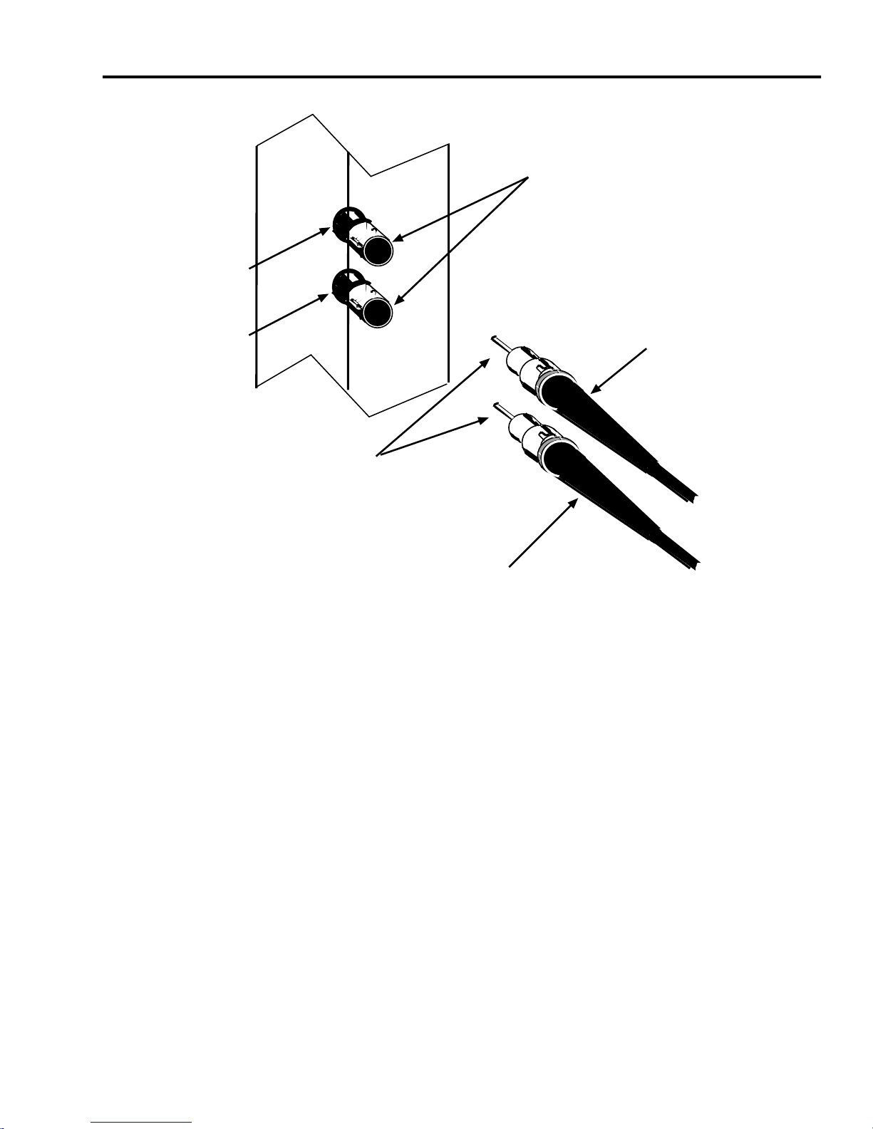
ST connectors attach to ST ports much like BNC connectors
attach to BNC ports. See Figure 3-3. The connector is inserted
into the port with an alignment key on the connector inserted into
the alignment slot on the port. The connector is then turned to
lock it down.
Caution: Do not touch the ends of the fiber optic strands and do
not let ends come in contact with contaminants. Contamination
of the ends causes problems in data transmissions. If the ends
become contaminated, clean them with a soft, clean, lint-free
cloth and alcohol.
Connect the fiber optic cable to the FOT-F3 as follows:
1. Remove the protective plastic covers from the fiber optic
ports on the FOT-F3 and the ends of the connectors on
each fiber strand. Save the co vers and replace them on the
connectors and ports whenever the fiber optic strands are
removed from the FOT-F3.
2. Attach the fiber labeled 1 to the bottom port, labeled RX on
the FOT-F3.
3. Attach the fiber labeled 2 to the top port, labeled TX.
4. At the other end of the fiber optic cable, attach the fiber
labeled 1 to the transmit port of the device.
5. Attach the fiber labeled 2 to the receive port.
3-6 FOT-F3 USER’S MANUAL
Page 27
T
X
CONNECTING THE FOT-F3 TO THE NETWORK
ST Fiber Optic
Ports
R
X
ST Connectors
Fiber 1
0461-08
Fiber 2
Figure 3-3 ST Connectors
6. Check that the LNK LED on the FOT-F3 is on. If the LED is
off, perform each of the following steps until the LED is on:
a. Check that the power is on for the device at the other
end of the link.
b. Verify that the fiber strands are properly connected to
each port.
c. Reverse the fiber optic cable ends at one end of the
fiber optic link segment.
FOT-F3 USER’S MANUAL 3-7
Page 28

CHAPTER 3: INSTALLATION
If a link is not established, contact Cabletron Systems Technical
Support. Refer to Chapter 1, Getting Help, for instructions.
3.3 SURFACE MOUNTING THE FOT-F3
Using the contents of the accessory package, you can mount the
FOT-F3 on a surface close to the workstation or on the
workstation itself.
The surface you choose should meet the following
requirements:
• Allows the fiber optic segment to be easily connected to the
transceiver .
• Allows the AUI cable to be easily connected from the
transceiver to the workstation.
• Has a smooth, dirt-free surface which accepts the adhesive
bonds.
Mount the FOT-F3 as follows:
1. Separate the two 1.5-inch x 3-inch Velcro mounts.
2. Peel off the paper that covers the adhesive backing of one
Velcro mount.
3. Carefully position the Velcro on the back of the FOT-F3.
Press firmly on the Velcro to affix it to the FOT-F3.
4. Similarly install the other half of the Velcro on the surface
on which you want to mount the FOT-F3.
5. Attach the FOT-F3 to the Velcro mount.
3-8 FOT-F3 USER’S MANUAL
Page 29

CABLE SUPPORT INSTALLATION
3.4 CABLE SUPPORT INSTALLATION
Relieve the strain from the cables attached to the FOT-F3,
whether or not the transceiver is mounted to a surface such as
a wall.
Note: Be sure each cable is securely attached to its port and that
the slide latch on the AUI connector is secured to the lock posts
on the AUI port. See Figure 3-2.
To provide strain relief to cables connected to a surface
mounted FOT-F3, proceed to Section 3.4.1. For a FOT-F3 that
is not surface mounted, proceed to Section 3.4.2.
3.4.1 Cable Strain Relief for Surface Mounted
FOT-F3
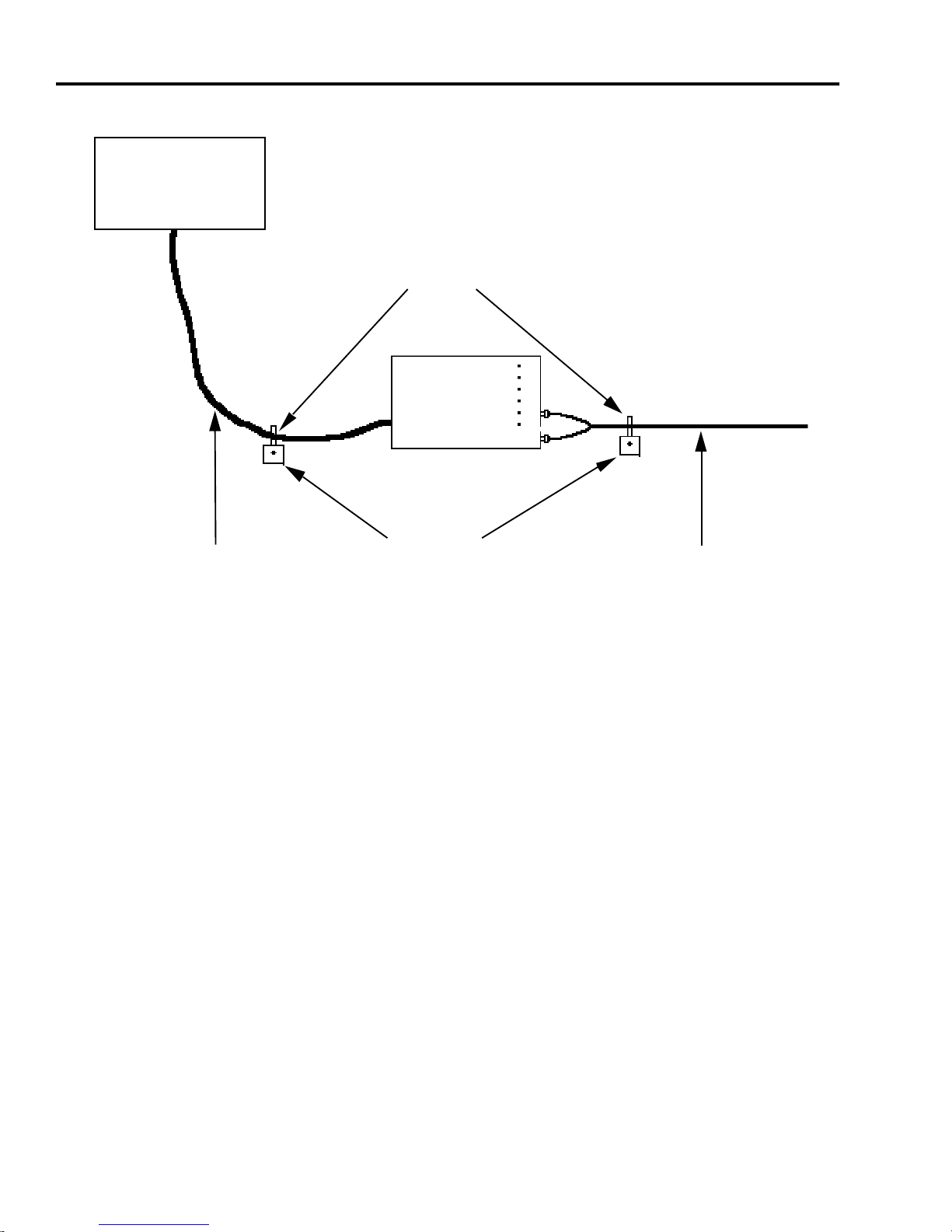
Refer to Figure 3-4 and proceed as follows to relieve the strain
on cables connected to a surface-mounted FOT-F3:
1. Remov e the protectiv e paper from one of the cable mounts
and attach the mount to the wall three inches from the
FOT-F3 fiber optic ports.
2. Repeat step 1, placing the other cable mount four inches
from the AUI port.
3. Use the tie wraps to secure each cable to its respective
cable mount.
FOT-F3 USER’S MANUAL 3-9
Page 30
CHAPTER 3: INSTALLATION
DEVICE
Tie Wraps
FOT-F3
AUI Cable
Cable Mounts
Fiber Optic
Segment
0461-09
Figure 3-4 Surface Mounting the FOT-F3
3.4.2 Cable Strain Relief for Non-Mounted FOT-F3
To relieve the strain to cables connected to a FOT-F3 that is not
surface mounted, proceed as follows:
1. If possible, use long tie wraps to secure the FOT-F3 to a
structural support such as a beam or a rafter.
2. Using additional long tie wraps, secure each cable to the
same structural support.
3-10 FOT-F3 USER’S MANUAL
Page 31

CABLE SUPPORT INSTALLATION
The FOT-F3 is now ready for operation. We recommend that
you test the system prior to transmitting data. Refer to
Chapter 4, Testing And Troubleshooting, for information
about how to test the system.
FOT-F3 USER’S MANUAL 3-11
Page 32

CHAPTER 3: INSTALLATION
3-12 FOT-F3 USER’S MANUAL
Page 33

CHAPTER 4
TESTING AND TROUBLESHOOTING
This chapter lists procedures to test the FOT-F3 after it is
connected to the network. A description of LANVIEW and its
function in troubleshooting physical layer network problems is
also provided.
4.1 INSTALLATION CHECK-OUT
This section contains procedures to test the following
• The fiber optic link segment to be attached to the FOT-F3.
• The FOT-F3 after it has been installed to ensure that the
physical layer of the network is operating properly.
4.1.1 Testing the Fiber Optic Link Segment
Test the segment being attached to the FOT-F3 to verify that the
cable meets the fiber budget specifications discussed in
Chapter 2. Using a fiber optic power meter set, test your link
segment as follows:
1. Attach a fiber optic jumper to the optical power meter. The
meter should be set at 1300 nm.
2. Attach a fiber optic jumper to the optical source unit. If the
source unit has multiple settings, it should be set at
1300 nm.
3. Using a barrel connector, connect the jumpers together.
FOT-F3 USER’S MANUAL 4-1
Page 34

CHAPTER 4: TESTING AND TROUBLESHOOTING
4. Following the instructions for the test set, test the jumpers
to get a reference level. Make a note of this reading.
5. Disconnect the jumpers from the barrel connector.
6. Using the jumper, attach the optical power meter to one
end of one strand of the link segment.
7. Using the other jumper, attach the other end of the same
strand to the optical source unit.
8. Take note of the reading on the optical power meter. This is
your test level.
9. Subtract the reference level found in step 4 from the test
level to find your dB loss for the fiber optic link segment,
i.e., dB loss = Test Level - Reference Level.
10. Verify that the reading on the receive unit matches the
specifications listed in the Fiber Optic Interface section of
Appendix A.
11. Repeat steps 6 through 10 for the other strand in the link
segment. If the fiber optic link segment does not meet the
specifications, try cleaning the connection at each end of
the cable with a soft, clean, lint-free cloth with alcohol, then
repeat the test. If this is unsuccessful, contact Cabletron
Systems Technical Support as described in Chapter 1,
Getting Help, for additional help.
4-2 FOT-F3 USER’S MANUAL
Page 35
INSTALLATION CHECK-OUT
4.1.2 Testing the FOT-F3 Fiber Optic Transceiver
Two Ethernet node testers capable of generating valid data
packets, such as the LAN-MD, are required for this procedure.
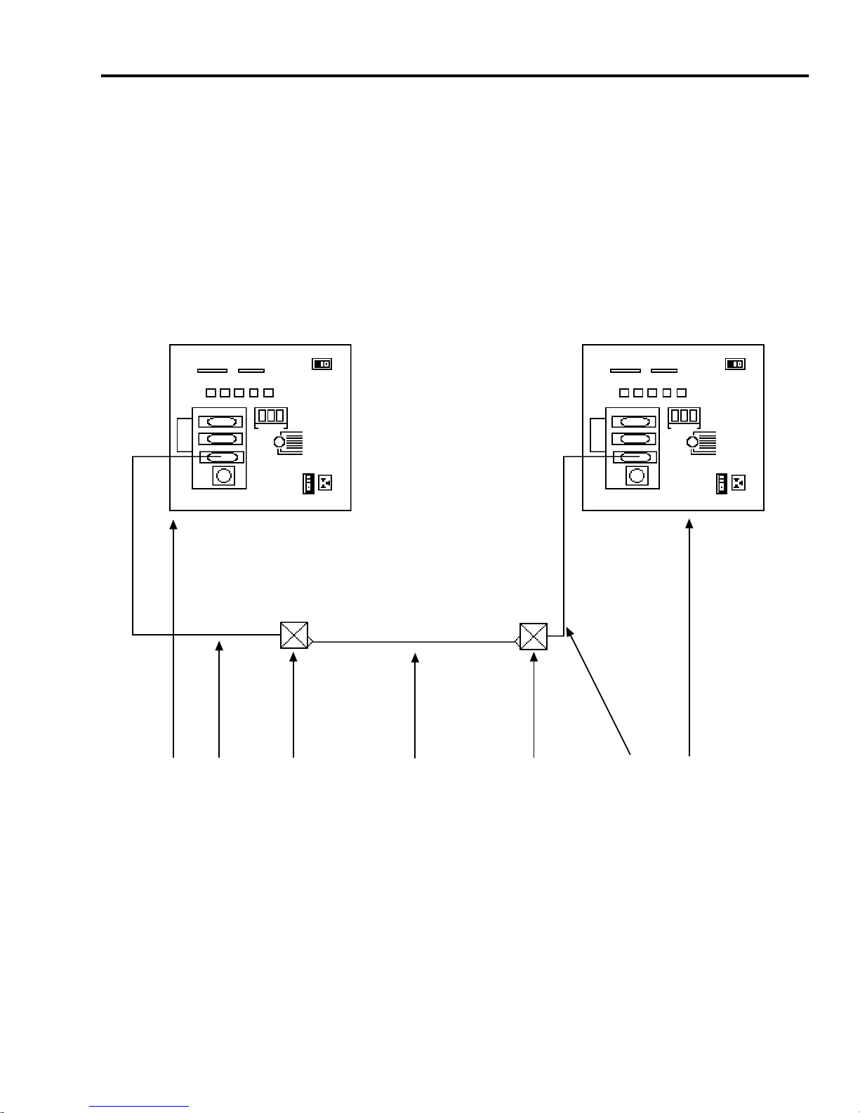
Refer to Figure 4-1 and proceed as follows:
1. Using an AUI cable (2), connect a LAN-MD (1) to the
FOT-F3 (3).
1 2 3 4 5 6 7
1. LAN-MD
2. AUI Cable
3. FOT-F3
4. Fiber Optic Segment
5. FOT-F3
6. AUI Cable
7. LAN-MD
Figure 4-1 Installation Checkout
FOT-F3 USER’S MANUAL 4-3
0461-10
Page 36

CHAPTER 4: TESTING AND TROUBLESHOOTING
2. Using another A UI cable (6), connect the other LAN-MD (7)
to another FOT-F3 (5) attached to the same fiber optic link
segment as the FOT-F3.
3. Select and run test 6 - SERVER on the LAN-MD connected
in step 1. Verify that this test passes.
• The status on the LAN-MD should read 000 if SQE is
enabled or 001 if SQE is disabled. A P ASS TEST
ST A TUS LED should also be lit on the LAN-MD.
• This LAN-MD now acts as the SER VER unit and will act
as a packet echoer when used with another LAN-MD.
4. Select and run test 4 - NODE on the LAN-MD connected in
step 2. Verify that this test passes. At least 100 packets
should be sent and received with no errors. The packets
will be received and sent back from the SERVER LAN-MD
that was left running on the other segment.
When the FOT-F3 has successfully completed this test, the units
are ready for normal operation. If any failures are noted, please
contact Cabletron Systems Technical Support.
4.2 USING LANVIEW
The FOT-F3 Fiber Optic Transceiver uses Cabletron Systems
LANVIEW, a built-in visual diagnostic and status monitoring
system. LANVIEW LEDs are more effective than a network
monitor because a network troubleshooter can quickly scan the
LEDs to diagnose network problems and to determine which
node or segment is faulty.
4-4 FOT-F3 USER’S MANUAL
Page 37
USING LANVIEW
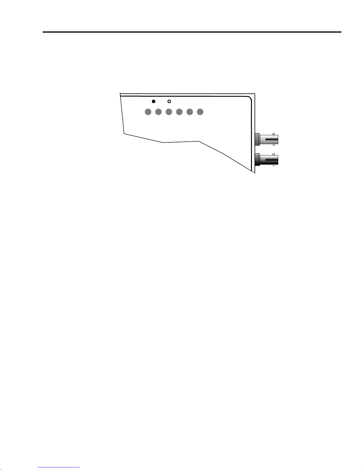
Figure 4-2 shows the location of the LANVIEW LEDs on the
FOT-F3. This is followed by a description of how to interpret the
indications of these LANVIEW LEDs.
SQE
FOT-F3
P
S
X
R
C
W
Q
M
R
E
C
T
V
L
L
N
N
K
TX
802.3 COMPATIBLE SINGLE MODE
FIBER OPTIC TRANSCEIVER
with LANVIEW
®
1300nm
RX
0461-11
Figure 4-2 LANVIEW LEDs
Optical Link OK (LNK) LED
When on, this green LED indicates that a link has been
established between the receive circuitry of the FOT-F3 and the
transmit circuitry of the fiber optic device at the other end of the
fiber optic link segment. This LED remains on as long as the link
is maintained.
To ensure that a link is maintained, the transceiver generates a
1 MHz idle signal when it is not transmitting data.
Collision (CLN) LED
This red LED flashes to indicate that the FOT-F3 is detecting a
collision condition. The frequency of flashes increases as the
network activity increases since more collisions are likely to
occur. The flash of the LED is pulse-stretched for easy viewing.
FOT-F3 USER’S MANUAL 4-5
Page 38

CHAPTER 4: TESTING AND TROUBLESHOOTING
Receive (RCV) LED
This yellow LED flashes to indicate that the transceiver is
receiving a frame from the network. The flash of the LED is pulse
stretched for easy viewing.
The LED flashes when traffic is on the network, even if the data
is not intended for the device attached to the FOT-F3.
Transmit (XMT) LED
This green LED flashes to indicate that a frame is being
transmitted onto the network by the device connected to the
transceiver. The flash of the LED is pulse stretched for easy
viewing.
This LED stays off if the device is active, but not transmitting
traffic onto the network.
Signal Quality Error (SQE) Test Function LED
When on, this yellow LED indicates the SQE test function is
enabled in the transceiver. When the LED is off, this indicates
that the SQE test is not enabled.
The SQE test is used to ensure that the collision presence circuit
and path are operational between the FOT-F3 and the Ethernet
device attached to the AUI port. This test is generated by the
transceiver after a data frame is transmitted through the
transceiver.
4-6 FOT-F3 USER’S MANUAL
Page 39

USING LANVIEW
Power (PWR) LED
When on, this green LED indicates that the transceiver is
receiving power from the device connected to the FOT-F3
AUI port.
If this LED is off, power is not being received from the device or
the DC-to-DC converter in the transceiver has failed.
FOT-F3 USER’S MANUAL 4-7
Page 40

CHAPTER 4: TESTING AND TROUBLESHOOTING
4-8 FOT-F3 USER’S MANUAL
Page 41

APPENDIX A
SPECIFICATIONS
This appendix contains the operational specifications for the
FOT-F3.
A.1 FIBER OPTIC INTERFACE
The FOT-F3 has ST fiber optic ports. Table A-1 lists the
parameters along with the associated typical, and minimum/
maximum specifications.
Table A-1 Fiber Optic Interface Specifications
Parameter Typical Minimum Maximum
Transmitter Peak
Wave Length:
Spectral Width: 95 nm — 125 nm
Rise Time/
Fall Time:
Duty Cycle: 50.1% 49.6% 50.7%
Bit Error Rate: Better than 10
1310 nm 1265 nm 1380 nm
3.0 ns/
2.5 ns
2.7 ns/
2.2 ns
-10
bit error rate
5.0 ns/
5.0 ns
FOT-F3 USER’S MANUAL A-1
Page 42

APPENDIX A: SPECIFICATIONS
Table A-1 Fiber Optic Interface Specifications (Continued)
Parameter Typical Minimum Maximum
Receive
Sensitivity:
Max. Receive
Input Power:
Transmitter Power
at 25°C Into
8.3/125 µm fiber:
Output Power
Coefficient:
-31.0 dBm -36.0 dBm -30.0 dBm
— — -14.0 dBm
-18.0 dBm -21.0 dBm -15.0 dBm
-0.07 dB/°C— —
Notes:
Transmitter Power decreases as temperatures rise and increases as
temperatures fall. Use the Output Power Coefficient to calculate
increased or decreased power output for your operating
environment. For example, the typical power output at 25°C is
-16.4 dBm. For a 4°C temperature increase, multiply the typical
coefficient (-0.07 dB) by four and add the result to typical output
power: (4° C x -0.07 dB
/°C
) + -16.4 dBm = -16.7 dBm).
The transmitter power levels and receive sensitivity levels given
above are Peak Power Levels after optical overshoot. You must use
a Peak Power Meter to correctly compare the values given above to
those measured on any particular port.
If you are measuring power levels with an Average Power Meter,
add 3 dBm to the measurement to correctly compare those
measured values to the values listed above
(i.e., -30.5 dBm peak = -33.5 dBm average).
A-2 FOT-F3 USER’S MANUAL
Page 43
AUI CONNECTOR
A.2 AUI CONNECTOR
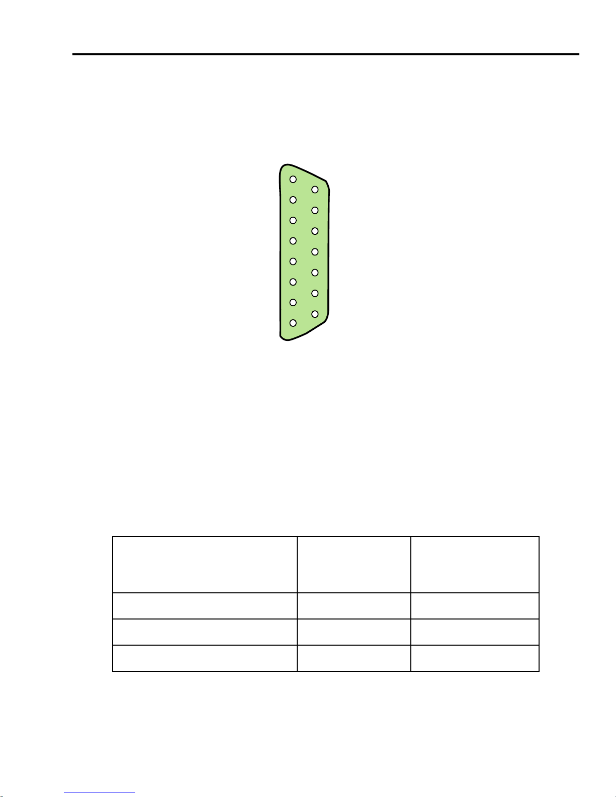
The AUI connector is a male DB15 receptacle with a metal shell
for cable shielding. Refer to Figure A-1 for pinout identification.
Pin 8 Logic Ref.
Pin 7 No Connection
Pin 6 Power Return
Pin 5 Receive +
Pin 4 Logic Ref.
Pin 3 Transmit +
Pin 2 Collision +
Pin 1 Logic Ref.
Pin 15 No Connection
Pin 14 Logic Ref.
Pin 13 Power (+12 Vdc)
Pin 12 Receive Pin 11 Logic Ref.
Pin 10 Transmit Pin 9 Collision -
0461-04
Figure A-1 AUI Connector Pinout Identification
A.3 POWER SUPPLY
Table A-2 provides the specifications of the power supply in the
FOT-F3.
Table A-2 Power Supply Specifications
Parameter
Current: 425 mA 475 mA
Input Voltage: 9.0 V 7.5 - 15.75 V
Reset Time: 500 ms 750 ms
FOT-F3 USER’S MANUAL A-3
Typical
Value
Worst
Case
Page 44

APPENDIX A: SPECIFICATIONS
A.4 ENVIRONMENTAL
Table A-3 provides the FOT-F3 environmental specifications.
Table A-3 Environmental Specifications
Parameter Specification
Operating Temperature: 5° to 55°C
Operating Humidity: 5% to 95% (non-condensing)
A.5 AGENCY APPROVALS
Safety
The FOT-F3 meets the safety requirements of UL1950, CSA
C22.2 No. 950, EN 60950, and 73/23/EEC.
Electromagnetic Compatibility
The FOT-F3 meets the EMC requirements of FCC Part 15
Class A, EN 55022 Class A, VCCI Class I, EN 50082-1, and
89/336/EEC.
A.6 PHYSICAL
The physical specifications are as follows:
Dimensions: 14.5 H x 8.5 W x 2.5 D cm
(5.7 H x 3.3 W x 1.0 D in)
Weight: 205 g (7.2 oz)
A-4 FOT-F3 USER’S MANUAL
 Loading...