

Page 1
EMME
SN
RESET
EMME
(ETHERNET MANAGEMENT
MODULE WITH ETHERNET)
USER’S GUIDE
BOK
STBYA
STBYB
RCVA
RCVB
RCVC
RCVD
ON PWR
ON PWR
ERR
STYBC
STBYD
CLNA
CLNB
CLNC
CLND
A
U
I
1
A
U
I
2
Page 2

NOTICE
Cabletron Systems reserves the right to make changes in specifications and other information
contained in this document without prior notice. The reader should in all cases consult Cabletron
Systems to determine whether any such changes have been made.
The hardware, firmware, or software described in this manual is subject to change without notice.
IN NO EVENT SHALL CABLETRON SYSTEMS BE LIABLE FOR ANY INCIDENTAL,
INDIRECT, SPECIAL, OR CONSEQUENTIAL DAMAGES WHATSOEVER (INCLUDING BUT
NOT LIMITED TO LOST PROFITS) ARISING OUT OF OR RELATED TO THIS MANUAL OR
THE INFORMATION CONTAINED IN IT, EVEN IF CABLETRON SYSTEMS HAS BEEN
ADVISED OF, KNOWN, OR SHOULD HAVE KNOWN, THE POSSIBILITY OF SUCH
DAMAGES.
Copyright 1995 by: Cabletron Systems, Inc., P.O. Box 5005, Rochester, NH 03866-5005
All Rights Reserved
Printed in the United States of America
Part Number: 9030514-04 November 1995
SPECTRUM, LANVIEW, Remote LANVIEW NCM-PCMMAC
trademarks and
MMAC-5FNB, MMAC-3FNB, CXRMIM, TPRMIM, FORMIM
Cabletron Systems, Inc.
All other product names mentioned in this manual may be trademarks or registered trademarks of
their respective companies.
Multi-Channel, Element Manager, EMME, EMME/LM, MMAC-8FNB
, and
, and
BRIM
are registered
EPIM
are trademarks of
,
EMME USER’S GUIDE i
Printed on
recycled paper.
Page 3

NOTICE
FCC NOTICE
This device complies with Part 15 of the FCC rules. Operation is subject to the following two
conditions: (1) this device may not cause harmful interference, and (2) this device must accept any
interference received, including interference that may cause undesired operation.
NOTE:
device, pursuant to Part 15 of the FCC rules. These limits are designed to provide reasonable
protection against harmful interference when the equipment is operated in a commercial environment.
This equipment uses, generates, and can radiate radio frequency energy and if not installed in
accordance with the operator’s manual, may cause harmful interference to radio communications.
Operation of this equipment in a residential area is likely to cause interference in which case the user
will be required to correct the interference at his own expense.
WARNING:
party responsible for compliance could void the user’s authority to operate the equipment.
This equipment has been tested and found to comply with the limits for a Class A digital
Changes or modifications made to this device which are not expressly approved by the
DOC NOTICE
This digital apparatus does not exceed the Class A limits for radio noise emissions from digital
apparatus set out in the Radio Interference Regulations of the Canadian Department of
Communications.
Le présent appareil numérique n’émet pas de bruits radioélectriques dépassant les limites applicables
aux appareils numériques de la class A prescrites dans le Règlement sur le brouillage radioélectrique
édicté par le ministère des Communications du Canada.
VCCI NOTICE
This equipment is in the 1st Class Category (information equipment to be used in commercial and/or
industrial areas) and conforms to the standards set by the Voluntary Control Council for Interference
by Information Technology Equipment (VCCI) aimed at preventing radio interference in commercial
and/or industrial areas.
Consequently , when used in a residential area or in an adjacent area thereto, radio interference may be
caused to radios and TV receivers, etc.
Read the instructions for correct handling.
ii EMME USER’S GUIDE
Page 4

NOTICE
CABLETRON SYSTEMS, INC. PROGRAM LICENSE AGREEMENT
IMPORTANT:
This document is an agreement between you, the end user, and Cabletron Systems, Inc. (“Cabletron”)
that sets forth your rights and obligations with respect to the Cabletron software program (the
“Program”) contained in this package. The Program may be contained in firmware, chips or other
media. BY UTILIZING THE ENCLOSED PRODUCT, YOU ARE AGREEING TO BECOME
BOUND BY THE TERMS OF THIS AGREEMENT, WHICH INCLUDES THE LICENSE AND
THE LIMITATION OF WARRANTY AND DISCLAIMER OF LIABILITY. IF YOU DO NOT
AGREE TO THE TERMS OF THIS AGREEMENT, PROMPTLY RETURN THE UNUSED
PRODUCT TO THE PLACE OF PURCHASE FOR A FULL REFUND.
Before utilizing this product, carefully read this License Agreement.
CABLETRON SOFTWARE PROGRAM LICENSE
1. LICENSE.
package subject to the terms and conditions of this License Agreement.
You may not copy, reproduce or transmit any part of the Program except as permitted by the
Copyright Act of the United States or as authorized in writing by Cabletron.
2. OTHER RESTRICTIONS. You may not reverse engineer, decompile, or disassemble the
Program.
3. APPLICABLE LAW. This License Agreement shall be interpreted and governed under the
laws and in the state and federal courts of New Hampshire. You accept the personal jurisdiction
and venue of the New Hampshire courts.
You have the right to use only the one (1) copy of the Program provided in this
EXCLUSION OF WARRANTY AND DISCLAIMER OF LIABILITY
1. EXCLUSION OF WARRANTY.
writing, Cabletron makes no warranty, expressed or implied, concerning the Program (including
its documentation and media).
CABLETRON DISCLAIMS ALL WARRANTIES, OTHER THAN THOSE SUPPLIED TO
YOU BY CABLETRON IN WRITING, EITHER EXPRESSED OR IMPLIED, INCLUDING
BUT NOT LIMITED TO IMPLIED WARRANTIES OF MERCHANTABILITY AND
FITNESS FOR A PARTICULAR PURPOSE, WITH RESPECT TO THE PROGRAM, THE
ACCOMPANYING WRITTEN MATERIALS, AND ANY A CCOMPANYING HARDW ARE.
2. NO LIABILITY FOR CONSEQUENTIAL DAMAGES
CABLETRON OR ITS SUPPLIERS BE LIABLE FOR ANY DAMAGES WHATSOEVER
(INCLUDING, WITHOUT LIMITATION, DAMAGES FOR LOSS OF BUSINESS,
PROFITS, BUSINESS INTERRUPTION, LOSS OF BUSINESS INFORMATION, SPECIAL,
INCIDENTAL, CONSEQUENTIAL, OR RELIANCE DAMAGES, OR OTHER LOSS)
ARISING OUT OF THE USE OR INABILITY TO USE THIS CABLETRON PRODUCT,
EVEN IF CABLETRON HAS BEEN ADVISED OF THE POSSIBILITY OF SUCH
DAMAGES. BECAUSE SOME STATES DO NOT ALLOW THE EXCLUSION OR
LIMITATION OF LIABILITY FOR CONSEQUENTIAL OR INCIDENTAL DAMAGES, OR
ON THE DURATION OR LIMITATION OF IMPLIED WARRANTEES IN SOME
INSTANCES THE ABOVE LIMITATIONS AND EXCLUSIONS MAY NOT APPLY TO
YOU.
Except as may be specifically provided by Cabletron in
. IN NO EVENT SHALL
EMME USER’S GUIDE iii
Page 5

NOTICE
UNITED STATES GOVERNMENT RESTRICTED RIGHTS
The enclosed product (a) was developed solely at private expense; (b) contains “restricted computer
software” submitted with restricted rights in accordance with Section 52227-19 (a) through (d) of the
Commercial Computer Software - Restricted Rights Clause and its successors, and (c) in all respects
is proprietary data belonging to Cabletron and/or its suppliers.
For Department of Defense units, the product is licensed with “Restricted Rights” as defined in the
DoD Supplement to the Federal Acquisition Regulations, Section 52.227-7013 (c) (1) (ii) and its
successors, and use, duplication, disclosure by the Government is subject to restrictions as set forth in
subparagraph (c) (1) (ii) of the Rights in Technical Data and Computer Software clause at 252.227-
7013. Cabletron Systems, Inc., 35 Industrial Way, Rochester, New Hampshire 03867.
iv EMME USER’S GUIDE
Page 6

TABLE OF CONTENTS
CHAPTER 1 INTRODUCTION
1.1 USING THIS MANUAL................................................................1-1
1.2 ETHERNET MANAGEMENT MODULE OVERVIEW..................1-2
1.2.1 Multi Media Access Center with Flexible Network Bus... 1-4
1.2.2 Repeater Interface Controller Media Interface Modules. 1-5
1.2.3 Ethernet Channels A, B, C, and D.................................. 1-6
1.2.4 Local Management .........................................................1-8
1.2.5 MIB Navigation ...............................................................1-8
1.2.6 LANVIEW LEDs.............................................................. 1-8
1.2.7 LANVIEWSECURE......................................................... 1-8
1.3 REPEATER FUNCTIONALITY..................................................1-10
1.4 BRIDGING FUNCTIONALITY...................................................1-10
1.5 MORE ABOUT BRIDGES.........................................................1-11
1.5.1 Filtering and Forwarding............................................... 1-12
1.5.2 Spanning Tree Algorithm.............................................. 1-13
1.6 ROUTING FUNCTIONALITY ....................................................1-13
1.7 COMMUNITY NAMES...............................................................1-15
1.8 SNMP (SIMPLE NETWORK MANAGEMENT PROTOCOL)....1-15
1.8.1 Management Information Base (MIBs)......................... 1-16
1.9 IP ADDRESSING ...................................................................... 1-16
1.9.1 Network ID.................................................................... 1-17
1.9.2 Host ID.......................................................................... 1-17
1.9.3 Subnet Addresses ........................................................1-17
1.9.4 Subnet Masks............................................................... 1-18
1.10 DEFAULT GATEWAY...............................................................1-19
1.11 MAC ADDRESS........................................................................1-19
1.12 NETWORK MANAGEMENT CAPABILITIES............................1-19
1.13 UNINTERRUPTIBLE POWER SUPPLIES (UPS).....................1-20
1.14 EMME UPGRADES...................................................................1-20
1.15 GETTING HELP........................................................................1-22
1.16 RELATED MATERIAL...............................................................1-22
EMME USER'S GUIDE
v
Page 7

TABLE OF CONTENTS
CHAPTER 2 NETWORK PLANNING AND CONFIGURATION
2.1 NETWORK REQUIREMENTS.....................................................2-1
2.2 EMME IN THE MULTI MEDIA ACCESS CENTER......................2-1
2.3 REPEATER MEDIA INTERFACE MODULES.............................2-2
2.3.1 Ethernet Port Interface Modules......................................2-4
2.4 SAMPLE NETWORK CONFIGURATIONS .................................2-5
2.4.1 Three Networks with a Single MMAC-FNB.....................2-6
2.4.2 Network with a Multi-port Router.....................................2-7
2.4.3 Configuring Additional Users to a Separate Segment.....2-8
2.4.4 Multiple Routed Sub-Networks......................................2-10
2.4.5 A Fault Tolerant Wiring Hierarchy.................................2-11
CHAPTER 3 INSTALLING THE EMME
3.1 UNPACKING THE EMME............................................................3-1
3.2 SETTING THE EMME MODE SWITCHES..................................3-2
3.3 INSTALLING THE EMME............................................................3-5
3.4 CONNECTING THE EMME TO THE NETWORK .......................3-7
CHAPTER 4 TESTING THE EMME
4.1 PRE-INSTALLATION TEST.........................................................4-1
4.2 INSTALLATION CHECK-OUT.....................................................4-3
CHAPTER 5 LOCAL MANAGEMENT
5.1 MANAGEMENT TERMINAL CONFIGURATION.........................5-2
5.1.1 Cable Configuration for the Management Terminal ........5-3
5.1.2 Cable Configuration for the UPS.....................................5-4
5.2 ESTABLISHING A TELNET CONNECTION ...............................5-4
5.3 LOCAL MANAGEMENT KEYBOARD CONVENTIONS..............5-5
5.4 ACCESSING LOCAL MANAGEMENT ........................................5-7
5.5 NAVIGATING LOCAL MANAGEMENT SCREENS.....................5-9
5.5.1 Selecting Local Management Menu Screen Items..........5-9
5.5.2 Exiting Local Management Screens..............................5-10
5.6 THE MAIN MENU SCREEN ......................................................5-11
5.7 SETUP MENU SCREEN ...........................................................5-12
vi
EMME USER'S GUIDE
Page 8

TABLE OF CONTENTS
5.8 THE SYSTEM LEVEL SCREEN ............................................... 5-13
5.8.1 System Level Screen Fields .........................................5-13
5.8.2 Setting the System Date............................................... 5-15
5.8.3 Setting the System Time............................................... 5-15
5.8.4 Setting the IP Address.................................................. 5-16
5.8.5 Setting the Subnet Mask............................................... 5-17
5.8.6 Setting the Default Interface .........................................5-17
5.8.7 Setting the Default Gateway......................................... 5-18
5.8.8 Configuring Console and Modem Ports........................ 5-19
5.9 SNMP COMMUNITY NAMES SCREEN...................................5-21
5.9.1 Setting SNMP Community Names................................ 5-22
5.10 SNMP TRAPS SCREEN...........................................................5-23
5.10.1 Trap Table Screen Fields .............................................5-23
5.10.2 Setting SNMP Trap Destinations..................................5-24
5.11 STATUS MENU.........................................................................5-25
5.12 THE COMPONENT STATUS SCREEN....................................5-26
5.12.1 Component Status Screen Fields.................................5-26
5.13 THE DEVICE STATISTICS SCREEN.......................................5-27
5.13.1 Device Statistics Screen Fields ....................................5-27
5.13.2 Selecting an Update-Freq.............................................5-29
5.13.3 Selecting a Network/Slot/Port.......................................5-29
5.13.4 Enabling Ports ..............................................................5-30
5.13.5 Disabling Ports..............................................................5-30
CHAPTER 6 MIB NAVIGATOR
6.1 MANAGING DEVICE MIBs .........................................................6-1
6.2 ACCESSING THE MIB NAVIGATOR..........................................6-2
6.3 MIB NAVIGATOR COMMAND SET OVERVIEW........................6-3
6.3.1 Conventions for MIB Navigator Commands ...................6-3
6.3.2 Navigation Commands ...................................................6-5
6.3.3 Built-In Commands .......................................................6-11
6.3.4 Special Commands....................................................... 6-17
CHAPTER 7 TROUBLESHOOTING
7.1 INTERPRETING THE LANVIEW LEDs.......................................7-1
7.2 TROUBLESHOOTING CHECKLIST...........................................7-4
7.3 USING THE RESET BUTTON....................................................7-6
7.4 BEFORE CALLING TECHNICAL SUPPORT..............................7-6
EMME USER'S GUIDE
vii
Page 9

TABLE OF CONTENTS
APPENDIX A IMAGE FILE DOWNLOAD USING OIDS
A.1 SETTING UP A UNIX WORKSTATION AS A TFTP SERVER... A-2
A.2 STANDARD LOCAL DOWNLOAD ............................................. A-3
APPENDIX B EMME OIDS
B.1 SPANNING TREE PROTOCOL .................................................B-1
B.2 PORT GROUP SECURITY......................................................... B-2
B.3 NETWORK AND CHANNEL LEVEL TRAPS.............................. B-5
B.4 BOARD LEVEL TRAPS.............................................................. B-6
B.5 PORT LEVEL TRAPS................................................................. B-7
B.6 BRIDGING .................................................................................. B-8
B.7 TRUNK PORT SECURITY .........................................................B-8
B.8 CHANNEL SELECTION .............................................................B-9
APPENDIX C EMME SPECIFICATIONS
C.1 BRIDGING FUNCTIONALITY.....................................................C-1
C.2 REPEATER FUNCTIONALITY...................................................C-2
C.3 CONSOLE PORT .......................................................................C-2
C.4 MODEM PORT ...........................................................................C-3
C.5 AUI PORTS.................................................................................C-3
C.6 ENVIRONMENTAL REQUIREMENTS.......................................C-4
C.7 FLASH EPROM ..........................................................................C-4
C.8 SAFETY......................................................................................C-4
C.9 SERVICE ....................................................................................C-4
C.10 PHYSICAL PROPERTIES..........................................................C-4
INDEX
viii
EMME USER'S GUIDE
Page 10

CHAPTER 1
INTRODUCTION
Welcome to the Cabletron Systems
(EMME) User’s Guide
description of the EMME and the information needed to install and
operate it in a Cabletron Systems Multi Media Access Center with the
Flexible Network Bus (MMAC-FNB).
A general knowledge of Ethernet and IEEE 802.3 type data
communications networks and their physical layer components is helpful
when using the EMME.
. This manual provides the technical user with a
Ethernet Management Module
1.1 USING THIS MANUAL
Before installing or operating the EMME, read through this manual to
familiarize yourself with its content and to gain an understanding of the
features and capabilities of the EMME. This manual is organized as
follows:
Chapter 1,
provides an overview of its multichannel capability that supports up to
four separate Ethernet segments. This chapter also explains the EMME
repeater and bridge functionality, concluding with a list of related
manuals.
Introduction
, discusses the capabilities of the EMME and
Chapter 2,
requirements to consider before installing the EMME. This chapter also
includes sample configurations demonstrating various applications for the
EMME.
Chapter 3,
the EMME into an MMAC-FNB, set the EMME’s mode switches, and
connect segments to the EMME.
Chapter 4,
EMME before it is installed and again after connecting it to the network.
Chapter 5,
Local Management provides tools to manage the EMME and its attached
segments.
EMME USER’S GUIDE Page 1-1
Network Planning and Configuration
Installing the EMME
Testing the EMME
Local Management
, explains the network
, provides instructions on how to install
, provides procedures for testing the
, describes EMME Local Management.
Page 11

CHAPTER 1
: INTRODUCTION
Chapter 6,
MIB Navigator
, describes MIB Navigator’s management and
control. The MIB Navigator manages EMME-related Management
Information Bases.
Chapter 7,
Troubleshooting
, details the Remote LANVIEW LEDs
incorporated into the EMME that enable you to quickly diagnose
problems that may occur with the module. This chapter also includes a
troubleshooting checklist, procedures for using the reset button, and
instructions for calling Technical Support if you need assistance.
Appendix A,
Image File Download Using OIDs
, provides instructions
for downloading an image file to the EMME by setting the MIB OID
strings.
Appendix B,
EMME OIDs
, contains selected OID strings which are
most often used.
Appendix C,
EMME Specifications
, contains location requirements and
operating specifications for the EMME.
1.2 ETHERNET MANAGEMENT MODULE OVERVIEW
The Cabletron Systems Ethernet Management Module with Ethernet
(EMME) is the heart of the Cabletron Systems Multi Media Access
Center. The EMME can provide four bridged and managed channels and
management for three separate Ethernet channels within a single MMAC.
This is accomplished by having channel A operate over the Power and
Management Bus, Cabletron’ s original Ethernet channel. Channels B and
C operate over the Flexible Network Bus (FNB). The EMME can also
bridge all three channels to a fourth externally connected channel (D,
usually a backbone connection), using one of the AUI ports on the
faceplate of the module.
The Cabletron Systems Ethernet non-repeater Media Interface Modules
use channel A on the MMAC backplane to communicate with the EMME
which performs the repeating function. MIMs provide a variety of
different media connections at one point within an MMAC. The EMME
incorporates an IEEE 802.3 repeater to provide repeater functionality for
these MIMs.
The EMME is fully compliant with IEEE 802.3 standards and provides
support for Spanning Tree IEEE 802.1d and DECnet.
Page 1-2 EMME USER’S GUIDE
Page 12

ETHERNET MANAGEMENT MODULE OVERVIEW
The EMME operates in conjunction with Cabletron Systems’ Repeater
Interface Controller (RIC) Media Interface Modules (MIMs) by using the
MMAC’s FNB Ethernet channels B and C.
The EMME is SNMP compliant and can be controlled and monitored by
numerous SNMP Network Management packages both remotely and
locally. EMME firmware also supports Distributed LAN Monitor (DLM)
and Full Remote Monitoring (RMON) groups including: Alarms, Events,
History, Hosts, Hosts Top N, Statistics, Matrix, Captive and Filter.
The EMME also provides the following:
• i960 RISC based processor
• Four bridged/routed Ethernet networks
• IEEE 802.1 D Spanning Tree and DEC Spanning Tree support
• IEEE 802.3 compliance
• Flash download capability for easy firmware downloads
• Standard FTP download capability
• LANVIEW diagnostic LEDs
• Special Filtering Data Base
• Complete SNMP management capability
• IETF MIB support including bridge, RMON, and MIBII
• Complete packet and error breakdown for all four channels
• Cabletron Systems’ Distributed LAN Monitoring (DLM) reducing
management traffic between network devices and management
platform
• Cabletron Systems’ cable redundancy
EMME USER’S GUIDE Page 1-3
Page 13
CHAPTER 1
: INTRODUCTION
1.2.1 Multi Media Access Center with Flexible Network
Bus
The Multi Media Access Center with Flexible Network Bus
(MMAC-FNB) pro vides the platform for the operation of the EMME. The
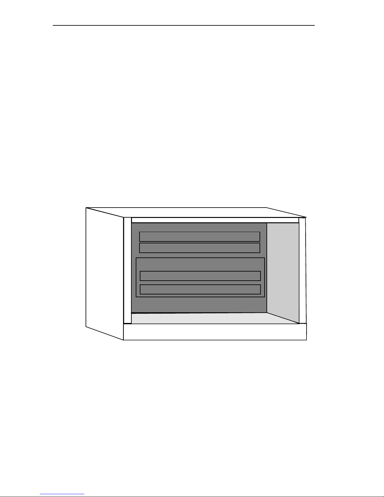
MMAC backplane provides three Ethernet buses designated as Ethernet
A, B, and C (See Figure 1-1). Cabletron Systems’ non-repeater MIMs
communicate over Ethernet A while Cabletron Systems’ repeater MIMs
use the Ethernet B and C buses. The EMME connects these buses to
provide bridging and management functionality.
There are two types of MMACs supporting Flexible Network Bus
architecture: shunting and non-shunting. Shunting supportive
MMAC-FNBs allow modules operating on either the Ethernet B or C bus
to continue communications with the EMME regardless of whether there
is an empty slot or an Ethernet A bus module between them in the chassis.
Power & Management Bus
Ethernet A Bus
Flexible Network Bus
Ethernet B Bus
Ethernet C Bus
Figure 1-1. MMAC Flexible Network Bus
051431
Page 1-4 EMME USER’S GUIDE
Page 14

ETHERNET MANAGEMENT MODULE OVERVIEW
Table 1-1 provides a list of the MMAC-FNB chassis where shunting
capabilities are set at the factory.
Table 1-1. MMAC-FNB Chassis
MMAC-FNB Chassis Serial No.
MMAC-3FNB
MMAC-5FNB
MMAC-8FNB
MMAC-M3FNB ALL
MMAC-M5FNB ALL
MMAC-M8FNB
FC
000000000 or above
CC
000000000 or above
CG
000000000 or above
DK
000000000 or above
1.2.2 Repeater Interface Controller Media Interface
Modules
Cabletron Systems’ MultiChannel family of Media Interface Modules
(MIMs) includes the Repeater Interface Controller (RIC), which is an
IEEE 802.3 compliant multi-port repeater. You can configure these
modules to operate on either the Ethernet B or C bus, via hardware
jumpers or management software. Software management overrides any
hardware configuration setting.
RIC technology provides the MIM with an inter-RIC bus, allowing
multiple RIC MIMs communicating over the RIC bus to act as a single
logical repeater. For example, an Ethernet frame taking a path from one
RIC MIM, to the Inter-RIC bus, to another RIC MIM (the frame being
retimed and regenerated to all ports from the last RIC MIM) has a path
cost equivalent to only one repeater hop. Since Ethernet networks are
limited to four serially linked repeaters, using the RIC repeater offers a
significant advantage. By using cascading RIC MIMs, each of which
support at least 13 cable segments, you can build a much larger network
than you could with stand-alone repeaters.
EMME USER’S GUIDE Page 1-5
Page 15

CHAPTER 1
: INTRODUCTION
1.2.3 Ethernet Channels A, B, C, and D
The EMME supports up to four Ethernet channels, provides management
for the four channels, and bridging between the ports. The four EMME
Ethernet channels access the same shared memory so that bridging
between the channels occurs concurrently.
TPMIM, FOMIM, and THNMIM
- The EMME provides repeater
functionality for these Cabletron Systems non-repeater Media Interface
Modules by using Ethernet channel A on the MMAC backplane to
transmit and receive data.
TPRMIM, FORMIM, and CXRMIM -
Ethernet channels B and C
transmit and receive pack ets o ver the Repeater Interface Controller (RIC)
management bus on the FNB to these Cabletron Systems RIC MIMs.
These MIMs can repeat packets autonomously without channeling them
through the EMME.
Third Party MIMs -
The EMME recognizes the third party MIMs listed
below and provides each module with support concerning the statistics on
the backplane and the control of channel selection for the entire module:
CSMIM2
•
- W ith supported connecti vity for channels A, B, or C in an
FNB chassis.
•
MODMIM -
With supported connectivity for channels A, B, or C in
an FNB chassis.
•
CRM-3E -
With supported connectivity for channels A, B, or C in an
FNB chassis.
•
PCMIM
- With supported connectivity for channel A in any MMAC
chassis.
•
SNACMIM-E
- With supported connectivity for channel A in any
MMAC chassis.
Page 1-6 EMME USER’S GUIDE
Page 16

ETHERNET MANAGEMENT MODULE OVERVIEW
FDDI and Token Ring Modules
- The EMME recognizes the following
FDDI and Token Ring modules, but the EMME management does not
provide control or statistics.
CRM-3T
•
•
SNACMIM
•
TRMIM-32A
•
TRMIM-34A
•
TRRMIM-F2T
•
TRRMIM-F3T
With TRMMIM version 2.02 or greater, both Token Ring and Ethernet
modules can reside in the same chassis and support physical management
capabilities of the Token Ring MIMs using the TRMMIM as the token
ring management module. Without the TRMMIM, the EMME will only
recognize the Token Ring modules.
Ethernet Channel D -
Ethernet channel D is provided by one of the two
redundant AUI ports on the front panel of the EMME. With the correct
transceiver, the AUI ports provide the capability for cable redundancy and
a variety of Ethernet transmission media connections, including twisted
pair, fiber optic, and thick or thin Ethernet coaxial cable.
Either one of the AUI ports can act as the bridge port to the external
network. When the EMME is first powered up, the AUI 1 port acts as the
bridge port and the AUI 2 port is off. Using the EMME’s network
management capabilities, you can reverse this configuration to have the
AUI 2 port act as the primary bridge port.
TPXMIM -
The EMME also supports Cabletron’ s family of Twisted Pair
Switching Media Interface Modules (TPXMIMs). These modules provide
board or individual port connectivity to any MMAC-FNB Ethernet
Channel (A, B, or C) with full SNMP management including RMON. All
ports initially default to Channel B upon power up and require a
Management Information Base (MIB) change to access any other
channel.
EMME USER’S GUIDE Page 1-7
Page 17

CHAPTER 1
: INTRODUCTION
1.2.4 Local Management
Built into the front panel of the EMME are two RJ45 ports. The Console
port allows access to Local Management by locally connecting a DEC VT
320 terminal, or a PC using VT320 emulation software. Refer to Chapter
5, Local Management.
1.2.5 MIB Navigation
EMME firmware supports a management tool through which you
navigate through Management Information Bases (MIBs). Refer to
Chapter 6, MIB Navigator.
1.2.6 LANVIEW LEDs
The EMME incorporates Cabletron Systems’ LANVIEW Status
Monitoring and Diagnostics System. Should a problem arise, such as a
power failure or a cable fault, the LANVIEW LEDs will help you to
diagnose it. The module includes the following LANVIEW LEDs:
• Board OK and Error LEDs for board status
• Standby, Receive, and Collision LEDs for Ethernet Channel Status
• On and Power LEDs for AUI Port Status
1.2.7 LANVIEW
SECURE
The EMME supports the LANVIEWSECURE suite of Ethernet MMAC
products. The LANVIEW
SECURE products support both inbound data,
“Intruder Prevention,” and outbound data, “Eavesdrop Prev ention.” These
products are identified by the words “LANVIEW
SECURE” printed on the
faceplate of the product.
Intruder prevention allo ws locking of ports when an intruder , based on the
expected MA C address assigned to that port, is seen on that port. A trap is
then generated and sent to the Network Management station to indicate an
intruder violation. When locking is enabled, the default configuration for
intruder prevention in LANVIEW
SECURE disables the port and sends a
trap to the management station. If the trap screen is configured
appropriately, through Local Management or setting OIDs, traps are sent
to the management station.
Page 1-8 EMME USER’S GUIDE
Page 18

ETHERNET MANAGEMENT MODULE OVERVIEW
Eavesdrop prevention delivers a modified data portion (filled with a
random pattern of binary ones and zeros) of the Ethernet packet to all
ports except the port specified in the original packet’s destination MAC
address field. Effectively all ports, except the actual destination port,
receive meaningless information. There are two learned MAC addresses
per port.
Full security allows the network administrator to configure the ports, so
that “broadcast” and “multicast” packets have the data portion of the
packet modified with a random pattern of ones and zeroes. Therefore, the
ports set to this mode do not see these packet types. The default setting for
“Full security” is disabled. Enabling the “Full security” function modifies
the broadcast and multicast packets.
LANVIEW
addresses per LANVIEW
SECURE products support assignment of up to 32 MAC
SECURE chip. The addresses can be assigned to
one or divided among several ports on the chip.
For LANVIEWSECURE products, trunk ports are defined as 3 or more
MAC addresses but may not exceed 34 MAC addresses, on that port, in
order to secure it. A port with 35 or more addresses can never be secured.
Ports with 3 - 34 MAC addresses can be secured and will need the
addresses manually entered to secure the port. Non-LANVIEW
SECURE
ports can only be secured with 2 or less MAC addresses associated with
that port. Non-LANVIEW
SECURE ports with three or more addresses can
never be secured.
LANVIEWSECURE is enabled upon locking a channel, module, or port.
When enabled, the first two addresses that are learned become the
expected address associated with that port on any LANVIEW
SECURE
module.
EMME USER’S GUIDE Page 1-9
Page 19

CHAPTER 1: INTRODUCTION
1.3 REPEATER FUNCTIONALITY
The EMME’s repeater functionality ensures that any problem segments
connected to any port on the MMAC-FNB will not affect any other
segments connected to the MMAC-FNB. For example, if 32 consecutive
collisions are detected on any segment, or if a collision detector is on for
more than 2.4 milliseconds, the EMME automatically partitions that
segment from the MMAC-FNB. The segment is automatically
reconnected to the MMAC-FNB when a good packet is transmitted onto
the segment.
For Cabletron Systems’ original non-repeater MIMs (i.e., TPMIM,
FOMIM) the EMME’s IEEE 802.3 compliant repeater provides the
MMAC-FNB with the ability to achieve maximum data paths on all
Ethernet transmission media, including 10BASE-T twisted pair, fiber
optic, and thick or thin Ethernet type cabling. To attain these maximum
data paths, the EMME retimes data packets and regenerates the preamble
of each data packet that enters the MMAC-FNB.
With the Cabletron Systems repeater modules (TPRMIM, CXRMIM, and
FORMIM), packets are repeated autonomously on the MIM and are not
channelled through the EMME. Module to module repeating is achieved
over the FNB backplane. The EMME provides management for these
modules and keeps Device, Network, Board, and Port Level performance
and error statistics.
1.4 BRIDGING FUNCTIONALITY
The EMME automatically configures itself as a bridge between channels
A, B, C, and D, for a four port bridge maximum. The EMME provides
802.1d compliant bridging capabilities to prevent unnecessary network
traffic from passing between segments.
Frames received by the EMME are forwarded to four megabytes of
buffering memory. The EMME’s processor accesses the frames from the
buffered memory and passes address information to the bridging
algorithm. Then, based on the bridging decision, the frames are filtered or
forwarded.
The EMME incorporates the Spanning Tree and DEC Spanning Tree
Algorithms that allow network architects to set up bridges in parallel
between segments as backup paths for fault tolerance. These bridges
remain in a standby condition until the primary parallel path fails.
Page 1-10 EMME USER’S GUIDE
Page 20

MORE ABOUT BRIDGES
1.5 MORE ABOUT BRIDGES
A bridge is a device that can be added to a network to allow expansion
beyond the limitations of IEEE 802.3. If an Ethernet network has a
repeater hop (count) of four repeaters or a propagation delay near the
51.2-microsecond maximum, a bridge can be used to build an extended
network. Ethernet bridges read in packets and decide to filter or forward
them based on the destination address of the packet. The simple forward/
filter decision process allows a bridge to segment traffic between two
networks, keeping local traffic local. This process increases the
availability of each network while still allowing traffic destined for the
opposite side of the bridge to pass.
Bridges are also used to connect similar networks such as Ethernet, Token
Ring, and Fiber Distributed Data Interface (FDDI) together. Note that
similar networks means that the upper five layers of the OSI model (see
Figure 1-2) are the same but may have different Data Link and Physical
layers. The Bridge operates at the Data Link level of the OSI model. It
stores packets and based on the packet destination address, forwards or
filters the packets. Because bridges work at layer 2 of the OSI model,
bridges are protocol independent. Bridges are slower than repeaters
because a bridge must read the complete data frame, check for errors, and
make forward or filter decisions based on recognized addresses stored in
its source address table.
7. APPLICA TION
6. PRESENTATION
5. SESSION
4. TRANSPOR T
3. NETWORK
2. DATA LINK
1. PHYSICAL
7
6
5
4
BRIDGE
3
2
1
Figure 1-2. OSI Model
7
6
5
4
3
2
1
EMME USER’S GUIDE Page 1-11
Page 21

CHAPTER 1: INTRODUCTION
The bridge is considered a node on the network and performs store and
forward functions for packets on each network. This contrasts with a
repeater which repeats the signal bit by bit from one side of the network
to the other. The bridge actually reads each packet, checks the packet for
accuracy, then decides whether the packet should be sent to the other
network based on the destination address. If the other network is busy, it
is the responsibility of the bridge to store the packet, for a reasonable
time, until the transmission can be made.
The bridge is also responsible for handling collisions. If a collision
happens as the bridge is transmitting onto the second network, the bridge
is responsible for the back off and retransmission process. The original
sending node is not made aware of the collision. It assumes the packet has
been sent correctly. If the bridge is unable to send the packet to its final
destination, the original sending station, expecting some response from
the device it was attempting to contact, will “time out” and depending on
the protocol attempt retransmission.
1.5.1 Filtering and Forwarding
The bridge decides whether to forward or filter a packet based on the
physical location of the destination device with respect to the source
device. A bridge dynamically learns the physical location of devices by
logging the source addresses of each packet and the bridge port the packet
was received on in a table called the Source Address Table (SAT).
The EMME supports the Special Filtering Database. This feature allows
the networks manager to define bridge filters above and beyond the
normal source and destination filters. The Special Filtering Database
allows filters to be configured for source, destination, type field, and a
flexible 64-byte offset to filter on information within the data portion of
the packet. A 64-byte window of data can search the data portion of the
packet to make filtering and forwarding decisions.
Page 1-12 EMME USER’S GUIDE
Page 22

ROUTING FUNCTIONALITY
1.5.2 Spanning T ree Algorithm
The Spanning Tree Algorithm (STA) is used by bridges to detect data
loops (duplicate data paths). The bridges will then automatically break the
loop and use the now blocked path as a backup in case the primary path
fails.
When a bridge is powered up, it goes through a series of self tests to
check its internal operation. During this time the bridge is in a standby
condition and does not forward traffic. Also during this standby period,
the bridge sends out special bridge management packets called
configuration Bridge Protocol Data Packets (BPDU). Bridges use the
BPDUs as a way of communicating with each other. The purpose of the
configuration BDPU is to notify other bridges on all of the connected
networks of the current topology. Based on the bridge priority and
address, the other bridges will automatically detect loops and negotiate a
single path. The bridge or bridges involved in this primary data path will
then come on-line and the bridges with lower priority involved in the
backup path(s) will go into a blocking condition.
The other type of BPDU is the topology change BPDU. This BPDU is
made up of four bytes and notifies the other bridges that a change has
taken place. Upon receipt of the topology change BPDU the bridges will
re-arbitrate, or re-span, to form a legal topology.
1.6 ROUTING FUNCTIONALITY
For routing functionality in the EMME, the following is needed:
• Routing Services software for the EMME module. A license must be
purchased for each module upgrade.
• 8-MB memory upgrade to bring the Dynamic Random Access
Memory (DRAM) up to a total of 12 MB. For information about 8-MB
upgrade kits, refer to the EMME Upgrades section at the end of this
chapter.
EMME USER’S GUIDE Page 1-13
Page 23

CHAPTER 1: INTRODUCTION
The Routing Services software provides the following additional
funtionality:
• Security via access lists
• Directed User Datagram Protocol (UDP) broadcast forwarding
• Support for multiple frame types:
- Internet Protocol (IP) and DECnet - Ethernet Type II and
SubNetwork Address Protocol (SNAP)
- Internet Packet Exchange (IPX) - Ethernet Type II, Novell, 802.2
and SNAP
• Statistics for host delivered and sourced packets
• Basic configuration via a local terminal
• Diagnostics via Telnet
• Flash download via Trivial File Transfer Protocol (TFTP)
With the Router Software loaded in the EMME, the EMME has the
options available for three network protocols. The user, through Local
Management, can select either IP, IPX, or DECnet Phase IV routing.
IP routing is the TCP/IP protocol that specifies how information is brok en
into packets, and how they are addressed to route over a network.
DECnet Phase IV specifies two forms of DECnet routing as follows:
• Phase IV or Level 1- For routing DECnet packets from one node to
another within a DECnet area.
• Area or Level 2 - For routing DECnet packets from one DECnet area
to another.
The DECnet Phase IV routing services are based on Digital Equipment
Corporation’s requirements for DECnet Phase IV, Level 1, and Area
routers.
Page 1-14 EMME USER’S GUIDE
Page 24

COMMUNITY NAMES
1.7 COMMUNITY NAMES
When using Local or Remote management tools to access the EMME, it
is important that the network manager has the ability to maintain network
security. Community names provide some network security by serving as
passwords to the device and the software running it. The network
manager (super user) establishes three (3) passwords, each of which
controls varying levels of access to the hardware and software. The
Community names are set through the Local Management SNMP
Community Names Table. Once these are set by the network manager,
they can be maintained in confidence or limited to users who have a need
to manage the system.
The three levels of access are:
• Super-User - Allows full management privileges
• Read Write - Allows edit of device configuration parameters not
including changing Community names
• Read Only - Allows reading of device parameters not including
Community names
1.8 SNMP (SIMPLE NETWORK MANAGEMENT
PROTOCOL)
SNMP is a protocol within the TCP/IP protocol suite. Network
applications such as Local Management and MIB Navigator use SNMP to
manage device configurations and monitor operating conditions. SNMP
protocol defines methods for “GETs,” “SETs,” and “TRAPs,” either
remotely from any point along the TCP/IP network or locally. This allows
for control of the device from any point along the network. MIB
Navigator uses the Management Information Base (MIB), located on the
device to be managed, to access information (GET), change device
parameters (SET), and to notify preselected users that an event has
occurred (TRAP).
EMME USER’S GUIDE Page 1-15
Page 25

CHAPTER 1: INTRODUCTION
1.8.1 Management Information Base (MIBs)
The MIBs are a database which are resident on the network device (i.e.,
EMME). Objects in the information base are uniquely identified by
administratively assigned identifiers (called object identifiers or OIDs)
and can be viewed, retrieved, or changed using an SNMP packet
exchange over the network or locally using MIB Navigator.
1.9 IP ADDRESSING
Each network interface or TCP/IP host is identified by a 32-bit binary
number called the IP address. This 32-bit number is divided into four
8-bit numbers called octets. Each octet is translated into its decimal
equiv alent and is represented using Dotted Decimal Notation (DDN). The
DDN format is XXX.XXX.XXX.XXX.
The IP address consists of two distinct parts, the Network ID and Host ID.
There are three classes of IP addressing: Class A, B, and C.
Tables 1-2 through 1-4 describe the classes.
Table 1-2. Class A
Range of Network IDs: 1 - 126.host.host.host
[1 octet for the Network ID (127
reserved)]
Binary translation:
(of first octet)
Range for the Host ID: net.1 - 254.1 - 254.1 - 254
Table 1-3. Class B
Range of Network
IDs:
Binary translation:
(of first octet)
128 -191.1 - 254.host.host
[2 octets for the Network ID]
1000000 - 10111111
[first bit is always 1 and second is always 0]
0000001 - 01111111
[first bit is always 0]
[3 octets for the Host ID - allows
16,777,214 hosts per network]
Range for the Host
ID:
Page 1-16 EMME USER’S GUIDE
net.net.1 - 254.1 - 254
[2 octets for the Host ID - allows 65,534 hosts
per network]
Page 26

Table 1-4. Class C
IP ADDRESSING
Range of Network
IDs:
Binary translation:
(of first octet)
Range for the Host
ID:
192 - 223.1 - 254.1 - 254.host
[3 octets for the Network ID]
1100000 - 11011111
[first and second bits always 1 and third is
always 0]
net.net.net.1 - 254
[1 octet for the Host ID - allows 254 hosts per
network]
1.9.1 Network ID
The Internet Assigned Numbers Authority (IANA) assigns the Network
ID and uniquely identifies a network on the Global Internet. On private
internal networks, unofficial IP addresses can be used allowing the
network address to be unique only within that internal network. (This is
not recommended by Cabletron.) The size of the Network ID is
determined by the class of the IP address.
1.9.2 Host ID
Host IDs are assigned by the local administrator . Since all hosts within the
same network share the same Network ID, each host must have a unique
Host ID. This allows for the identification of each host within the netw ork
based on this portion of the IP address. The class of IP address used
determines the size of the Host ID.
1.9.3 Subnet Addresses
Subnet addresses are used to partition an IP network into multiple
subnetworks or subnets. The use of Subnet addresses adds an additional
layer of hierarchy to the IP addressing scheme. This additional addressing
layer facilitates isolation, control, and administration of users within the
network. This is done by grouping hosts into separate subnets. Use of
subnet addresses on the network means using a subnet mask in
conjunction with each IP address.
EMME USER’S GUIDE Page 1-17
Page 27

CHAPTER 1: INTRODUCTION
1.9.4 Subnet Masks
The purpose of the subnet mask is to indicate the part of the Host ID that
is being used as a Subnet address. By default no part of the Host ID is
used, and therefore, the default or “Natural Mask” masks just the octets
that comprise the Network ID. Table 1-5 shows the default masks.
Table 1-5. Class and Default Masks
Network Class Length of Network ID Default Mask
Class A X. 255.0.0.0
Class B X.X. 255.255.0.0
Class C X.X.X. 255.255.255.0
The binary 1’s in the mask “mask-out” the Network ID and the 0’s show
where the Host ID is. When using part of the Host ID as a subnet address,
define a subnet mask that will mask-out the bits of the Host ID that are
being used as a subnet address. The calculations for the mask must be
done at the bit level since in some cases, al w ays in Class C addresses, the
last octet must be split into part Host ID and part Subnet address.
Table 1-6 shows how using the mask determines the subnet and Host
addresses that are available from the octet.
Table 1-6. Examples of Subnet Masks
Decimal
Mask
255 11111111 1 - 254 None
254 11111110 2 - 254 (Even numbers only) None
252 11111100 4 - 252 (Multiples of 4 only) 1 and 2
248 11111000 8 - 248 (Multiples of 8 only) 1 - 6
240 11110000 16 - 240 (Multiples of 16 only) 1 -14
224 11100000 32, 64, 96, 128, 192, 224 1 - 30
192 11000000 64 and 192 1 - 62
Binary
Equivalent
Available Subnet
Addresses
Available
Host IDs
Page 1-18 EMME USER’S GUIDE
Page 28

DEFAULT GATEWAY
1.10 DEFAULT GATEWAY
The default gateway is the IP address of the network or host to which all
packets addressed to unknown network or host are sent. The default
gateway should be a perimeter or border de vice that connects the netw ork
with the rest of the world. The default gateway attempts to route the
packet to the correct destination. This gateway is often used by managers
to handle all traffic between pri v ate networks and the Internet. If a def ault
gateway is not defined the packets addressed to a netw ork or host address
not found in the forwarding table will be dropped.
1.11 MAC ADDRESS
The MAC address is a unique, 48-bit binary number, associated with a
specific physical connection to a network. MAC addresses are divided
into 6 octets, and represented in hexadecimal form such as the following:
00-00-1D-00-26-FB
The MAC addresses are administered by the IEEE and are generally
assigned at the time of manufacture, and cannot be changed. The first
three octets uniquely identify the manufacturer . Cabletron de vices all start
with: 00-00-1D.
1.12 NETWORK MANAGEMENT CAPABILITIES
The Cabletron Systems EMME can be controlled and managed by any
SNMP network management system. These include:
• Cabletron Systems SPECTRUM
• Cabletron Systems SPECTRUM Element Manager for Windows
• Third Party SNMP compliant Network Management Packages
The EMME’s network management capabilities provide the necessary
management tools for the EMME to operate at its full capacity. Your
ability to set up parameters with network management ensures optimal
performance of the EMME.
EMME USER’S GUIDE Page 1-19
Page 29

CHAPTER 1: INTRODUCTION
For example, you can gather a large amount of statistical information
about the EMME, including the quantities of the following.
– Packets – Receive Collisions
– Transmit Collisions – Giant Packets
– Runt Packets – Misaligned Packets
– CRC Error – Out of Window Collisions
– Bytes Received
For further specific information, refer to the applicable Network
Management Package User’s Manual.
1.13 UNINTERRUPTIBLE POWER SUPPLIES (UPS)
The EMME can monitor and control American Power Conversion UPSs.
The EMME modem port is connected to the UPS via a DB9-to-RJ45
adapter (Cabletron Part Number 9372066).
This feature supports two methods for activating the UPS monitoring as
follows:
• Using the Local Management, System Level screen of the EMME via
a system connected to the EMME console port.
• Using SPECTRUM Element Manager for Windows, SPECTRUM
Portable Management Application (SPMA), or SPECTRUM. These
software packages provide Graphical User Interfaces (GUI) to
configure the UPS.
1.14 EMME UPGRADES
To take advantage of enhanced EMME features, a Dynamic Random
Access Memory (DRAM) upgrade is required. These are DRAM modules
that are only available through Cabletron Systems. The DRAM modules
provide additional memory required to support the following:
– Routing – Matrix
– RMON MIB Host – Captive
– Hosts Top N – Filter Groups
Page 1-20 EMME USER’S GUIDE
Page 30

EMME UPGRADES
To determine the upgrade required for a specific EMME, the EMME
board revision le vel must be kno wn. The re vision le vel can be found using
one of the following:
• Local Management, where it is shown on the Password screen
• MIB Navigator, described in Chapter 6
The OID used to determine the EMME revision is eMMEHRev, which is:
1.6.1.4.1.52.1.6.2.9.2
This is a read only function.
NOTE
Table 1-7 lists the EMME board revisions along with the associated
DRAM Upgrade Kits and their part number.
Table 1-7. EMME Boards and Associated DRAM Upgrade Kit.
EMME Board
Revision
05 and 07 Static Column 8MB-SC-UGK60
06, 08, and 09 Fast Page Mode 8MB-FPM-UGK60
DRAM Upgrade Kit
Type
8-MB DRAM
Part No.
Revisions 04 and below do not support a SIMM socket.
NOTES
The EMME only supports Static Column and Fast Page
Mode DRAM from Cabletron Systems.
EMME USER’S GUIDE Page 1-21
Page 31

CHAPTER 1: INTRODUCTION
1.15 GETTING HELP
For additional support related to the EMME or for any questions,
comments, or suggestions related to this manual, contact Cabletron
Systems Technical Support by any of the following methods.
Mail: Cabletron Systems, Inc.
P.O. Box 5005
Rochester, NH 03866-5005
Phone: (603) 332-9400, Mon-Fri 8AM to 8PM EST
CompuServe: GO CTRON from any ! prompt
Internet Mail: [email protected]
By FTP 134.141.197.25
Login: anonymous, Password: your email
address
1.16 RELATED MATERIAL
The manuals listed below should be used to supplement the procedures
and other technical data provided in this manual. The procedures will be
referenced where appropriate, but will not be repeated.
Cabletron Systems’ MMAC Overview and Setup Guide
Cabletron Systems’ Repeater Interface Controller Media Interface
Modules (TPRMIM/FORMIM/CXRMIM) Installation Guide
Cabletron Systems’ SPECTRUM Element Manager for Windows
User’s Manual
The Simple Book, An Introduction to Management of TCP/IP-based
Internets, Marshall T. Rose, Prentice-Hall, Inc., 1991
Interconnection, Bridges, and Routers, Radia Perlman,
Addison-Wesley, 1992
Internetworking with TCP/IP, Vol. I, Douglas E. Corner, Prentice-Hall,
1991
Page 1-22 EMME USER’S GUIDE
Page 32

CHAPTER 2
NETWORK PLANNING AND CONFIGURATION
Before you attempt to install the Cabletron Systems EMME, review the
requirements outlined in this chapter. Also, refer to the operating
specifications and environmental requirements that are listed.
All conditions, guidelines, specifications and requirements included in
this chapter must be met to insure satisfactory performance of the EMME.
Failure to follow these guidelines will result in unsatisfactory network
performance.
2.1 NETWORK REQUIREMENTS
When connecting a network segment to the EMME, via a transcei ver and
an AUI cable, you will need to make sure that the following requirements
are met:
• The transceivers used to connect the EMME meet Ethernet Version 2
or IEEE 802.3 standards.
• The AUI cables connecting the EMME to the transceivers on the
network match the transceiv er type on the netw ork se gment, Ethernet
Version 1, Version 2, or IEEE 802.3 type cables, and do not exceed 50
meters in length.
2.2 EMME IN THE MULTI MEDIA ACCESS CENTER
The EMME is designed to be installed in the Cabletron Systems Multi
Media Access Center (MMAC). The MMAC-FNB (Flexible Network
Bus) hub series provides the platform for multiple separately repeated
Ethernet segments. The FNB backplane pro vides two additional b uses for
Ethernet channels B and C. The MMAC Ethernet A channel, supports
Cabletron’s non-repeater Ethernet modules, while Ethernet channels B
and C support Cabletron’s family of repeater MIMs.
EMME USER’S GUIDE Page 2-1
Page 33

CHAPTER 2: NETWORK PLANNING AND CONFIGURATION
2.3 REPEATER MEDIA INTERFACE MODULES
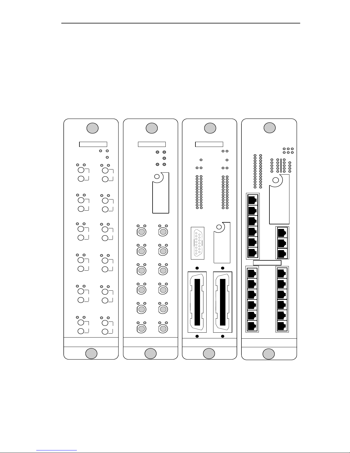
Repeater Media Interface Modules (RMIMs) also called RICMIMs for
Repeater Interface Control MIMs, shown in Figure 2-1, are based on
Repeater Interface Technology that enables each of the modules to function
as an independent 802.3 compliant multi-port repeater . The EMME
communicates with the repeater MIMs over Ethernet channels B and C of
the FNB. The following repeater MIMs are currently available:
• CXRMIM
- The coaxial version of the repeater MIM is equipped with twelve
10BASE-2 coaxial connectors. The module also includes an EPIM
port.
• FORMIM-22
- The FORMIM-22 includes twelve FOIRL/10BASE-F ports with
ST type connectors.
• TPRMIM-20/-22
- These MIMs are equipped with RJ45 connectors and one user
configurable Ethernet Port Interface Module (EPIM) which
provides a single port interface for an AUI, fiber optic, twisted
pair, or coaxial connection. The TPRMIM-20 has nine RJ45
connectors and the TPRMIM-22 has twenty-one RJ45 connectors.
• TPRMIM-33/-36
- These MIMs come equipped with 50-pin champ connectors, (the
TPRMIM-33 with one and the TPRMIM-36 with two). Each
connector provides the MIM with 10BASE-T twisted pair ports
(twelve for each champ connector). These MIMs also ha v e a user
configurable Ethernet Port Interface Module (EPIM) providing a
single port interface. The TPRMIM-36 also has an AUI port.
• TPXMIM-20/-22
- These MIMs are equipped with RJ-45 connectors and one user
configurable EPIM. The TPXMIM-20 has nine RJ-45 ports while
the TPXMIM-22 has 21.
Page 2-2 EMME USER’S GUIDE
Page 34
REPEATER MEDIA INTERFACE MODULES
• TPXMIM-33/-34
- These MIMs are equipped with 50 pin Champ connectors and one
user configurable EPIM. The TPXMIM-33 has one 50 pin Champ
connector and the -34 has two.
FORMIM-22
SN
ETHERNET
RCV LNK
TX
RX
TX
RX
TX
RX
TX
RX
TX
RX
TX
RX
7
RCV LNK
8
RCV LNK
9
RCV LNK
10
RCV LNK
11
RCV LNK
12
FOIRL/10BASE-FL
ETHERNET
B C
RCV LNK
RCV LNK
RCV LNK
RCV LNK
RCV LNK
RCV LNK
CLN
CXRMIM
SN
ETHERNET
1
2
8
3
9
4
10
11
5
12
13
6
RCV
POKRCV POKRCV
10BASE-2
ETHERNET
B C
CLN
POK
1
2
3
4
5
6
7
TPRMIM-36
SN
CLN
14
RCV POK
15
16
17
18
19
20
21
22
23
24
25
26
L
R
N
C
K
V
14
26
15
10BASE-T
ETHERNET
ETHERNET
1
2
3
4
5
6
7
8
9
10
11
12
13
B C
CLN
RCV POK
R
C
V
TPXMIM-22
CLN
RCV LNK RCV LNK
6
7
8
9
10
A B C
1
2
3
4
5
E
PI
M
2
X
3
X
4
X
5
X
6
X
7
X
8
X
9
X
10
X
ETHERNET
RCV LNK
11
12
13
14
15
16
17
18
19
20
21
22
11
X
L
N
K
1
12
X
13
X
14
X
15
X
16
X
SN
17
13
2
X
18
X
19
X
20
X
21
X
22
X
10BASE-T
ETHERNET
EMME USER’S GUIDE Page 2-3
051433
Figure 2-1. Sample Repeater MIMs
Page 35
CHAPTER 2: NETWORK PLANNING AND CONFIGURATION
2.3.1 Ethernet Port Interface Modules
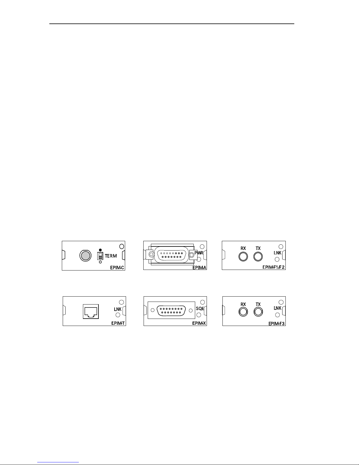
For an additional connection to the Ethernet network, the TPRMIM-20/
22, TPRMIM-33/36, and CXRMIM utilize the Cabletron Systems
Ethernet Port Interface Modules (EPIMs), Figure 2-2, that allow you to
connect the unit directly to:
• Thin-net cable from the Coaxial Interface Module (EPIM-C).
• Unshielded twisted pair cable from the 10BASE-T Twisted Pair
Interface Module (EPIM-T).
• AUI cable, to an external transceiver, from the AUI Interface Module
(EPIM-A).
• AUI cable directly from the Transceiver Interface Module with dual
internal transceivers (EPIM-X).
• Multi-Mode Fiber Optic Cable, with SMA or ST connectors, from the
Fiber Optic Interface Modules (EPIM-F1/ EPIM-F2).
• Single Mode Fiber Optic Cable, with ST connectors, from the single
mode Fiber Optic Interface Module (EPIM-F3).
RX TX
TERM
EPIM-C
PWR
EPIM-A
EPIM-C EPIM-A EPIM-F1/F2
LNK
EPIM-T
SQE
EPIM-X
RX TX
EPIM-T EPIM-X EPIM-F3
Figure 2-2. Ethernet Port Interface Modules (EPIMs)
LNK
EPIM-F1/F2
LNK
EPIM-F3
Page 2-4 EMME USER’S GUIDE
Page 36

SAMPLE NETWORK CONFIGURATIONS
To support the additional functionality of the LANVIEWSECURE
products, the EPIMs used in products that support LANVIEW
SECURE
must be at or above the revision levels listed in Table 2-1. The EPIM
revision le vel is located on the EPIM module and consists of two numbers
following the dash (-) at the end of the part number (e.g., 9031111-xx).
Table 2-1. EPIM Board Revisions
EPIM
EPIM-3PS Not Applicable
EPIM-A Not Applicable
EPIM-C 05 or greater
EPIM-F1 05 or greater
EPIM-F2 05 or greater
EPIM-F3 02 or greater
EPIM-T 04 or greater
EPIM-X 02 or greater
EPIM BOARD
REVISION
2.4 SAMPLE NETWORK CONFIGURATIONS
This section provides you with sev eral examples for configuring networks
with the EMME. These following network configuration examples
illustrate the flexibility and advantages to using the EMME and RIC MIM
technology:
• Three networks within a single MMAC-FNB
• A network with a multi-port router
• Adding users to an existing network
• Seven individual networks with a single MMAC-FNB
• A fault tolerant wiring scheme
EMME USER’S GUIDE Page 2-5
Page 37
CHAPTER 2: NETWORK PLANNING AND CONFIGURATION
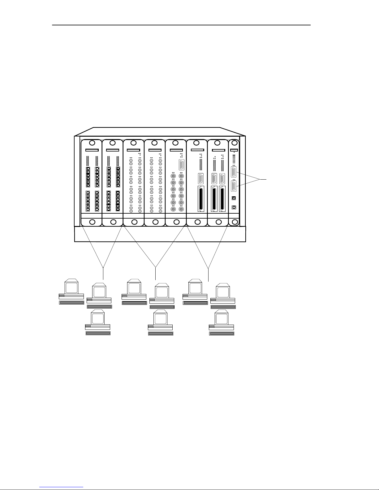
2.4.1 Three Networks with a Single MMAC-FNB
One of the basic applications of the EMME is for configuring three
separate networks with one MMAC-FNB. This provides you with the
advantages of having three separate networks in one wiring closet, with
full bridging and SNMP management for each network. Figure 2-3
illustrates an example of the three network configuration.
TPMIM-24
Channel A
CXRMIMFORMIM-22FORMIM-22TPMIM-24
Channel B Channel C
TPRMIM-33
TPRMIM-36
EMME
To Backbone
Channel D
Figure 2-3. Single MMAC-FNB Configuration
Page 2-6 EMME USER’S GUIDE
051435
Page 38
SAMPLE NETWORK CONFIGURATIONS
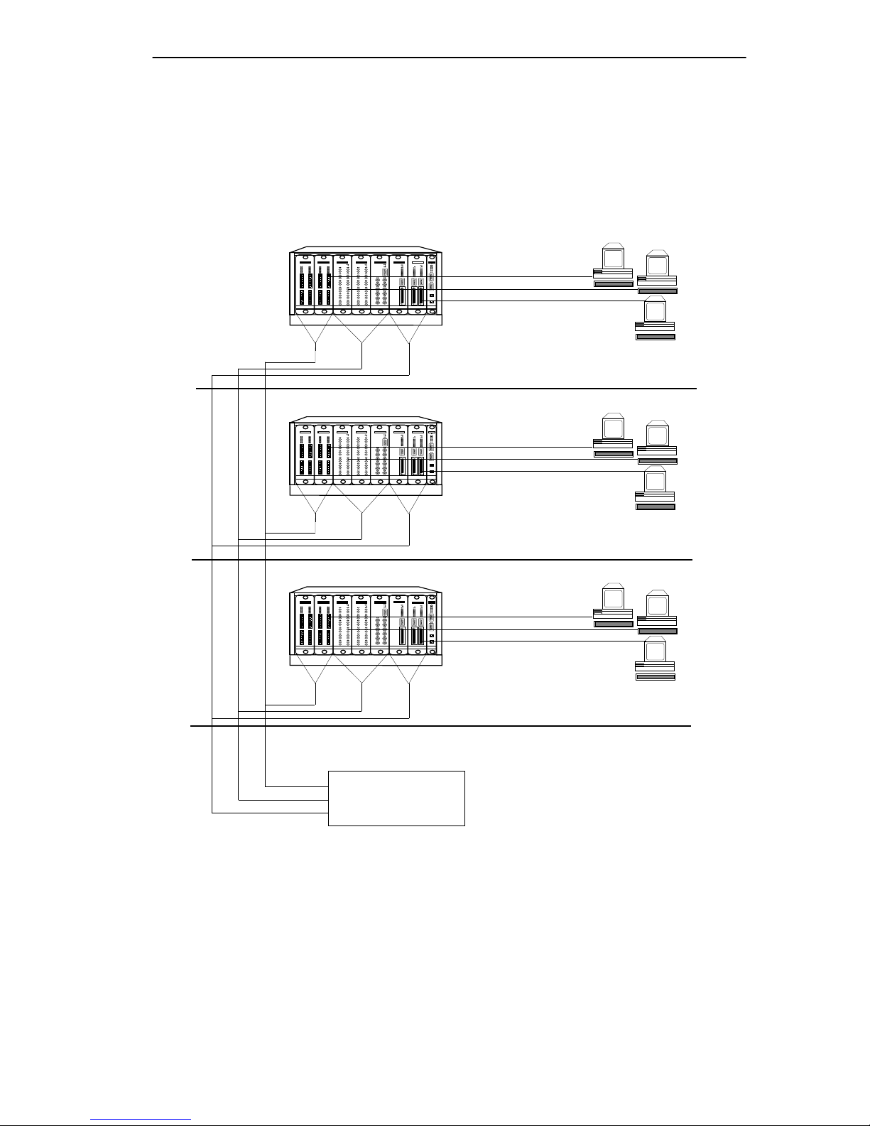
2.4.2 Network with a Multi-port Router
Another application of the EMME is configuring two or three separate
networks within the same building. Using a multi-port router, you can
interconnect the three networks Figure 2-4 illustrates an example of the
multi-port router configuration.
TPMIM-24
TPRMIM-33
CXRMIMFORMIM-22FORMIM-22TPMIM-24
EMME
TPRMIM-36
AB C
TPMIM-24
TPRMIM-33
CXRMIMFORMIM-22FORMIM-22TPMIM-24
EMME
TPRMIM-36
AB C
TPMIM-24
TPRMIM-33
CXRMIMFORMIM-22FORMIM-22TPMIM-24
EMME
TPRMIM-36
4th Floor
3rd Floor
AB
C
2nd Floor
MULTI-PORT
ROUTER
051436
Figure 2-4. Multi-Port Router Configuration
EMME USER’S GUIDE Page 2-7
Page 39

CHAPTER 2: NETWORK PLANNING AND CONFIGURATION
2.4.3 Configuring Additional Users to a Separate
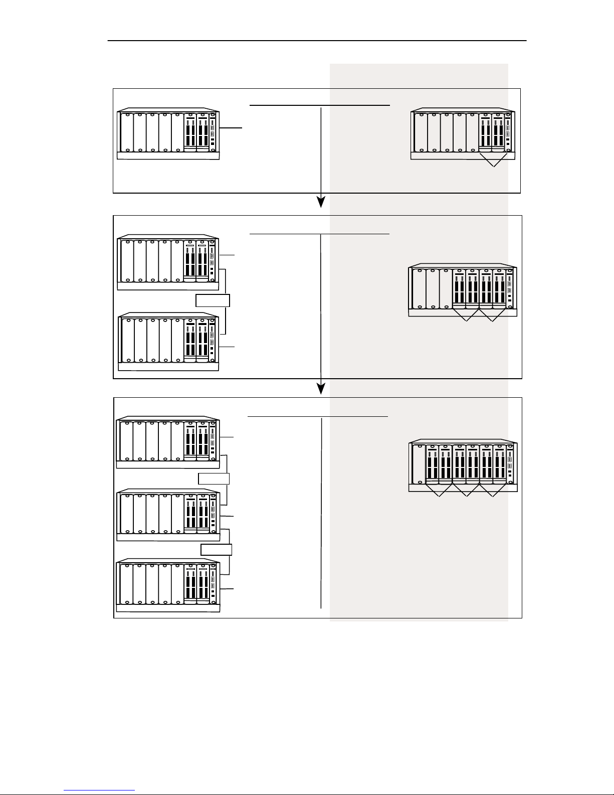
Segment
Before the EMME was available, adding users to a separately repeated
segment required investing in a great deal of additional equipment. The
example in Figure 2-5 has one Ethernet segment using; the pre-EMME
technology for 48 users requires an MMAC, an IRM2 and two 24-port
MIMs. Each time you want to add an additional 48 users to a separately
repeated segment, you must add an MMAC-FNB, IRM2, two 24-port
MIMs, and an external bridge.
When you use the new technology of the EMME, adding new users on a
separately repeated segment can be accomplished simply by adding
MIMs to the MMAC-FNB.
Page 2-8 EMME USER’S GUIDE
Page 40
SAMPLE NETWORK CONFIGURATIONS
CURRENT TECHNOLOGY
CURRENT TECHNOLOGY
TPMIM-24
IRM3
TPMIM-24
48 Users
- an MMAC
- an IRM2
- two 24-port MIMs
An Additional 48 Users Require:
TPMIM-24
IRM3
TPMIM-24
48 Users
- an additional MMAC
Bridge
- an additional IRM2
- two additional
TPMIM-24
24-port MIMs
IRM3
TPMIM-24
- an external bridge
48 Users
Initial 48 Users
- an MMAC-FNB
- an EMME
- two 24-port
RIC MIMs
- two additional
24-port RIC MIMs
NEW TECHNOLOGY
NEW TECHNOLOGY
TPMIM-24
TPMIM-24
Channel B
48 Users
TPMIM-24
TPMIM-24
Channel C
48 Users
TPMIM-24
TPMIM-24
Channel C
48 Users
EMME
EMME
Another Additional 48 Users Require:
TPMIM-24
IRM3
TPMIM-24
48 Users
TPMIM-24
TPMIM-24
TPMIM-24
Channel B
48 Users
TPMIM-24
TPMIM-24
- an additional MMAC
- an additional IRM2
Bridge
- two additional
TPMIM-24
24-port MIMs
IRM3
TPMIM-24
- an external bridge
- two additional
24-port
non-RIC MIMs
Channel A
48 Users
TPMIM-24
Channel C
48 Users
EMME
48 Users
Bridge
TPMIM-24
IRM3
TPMIM-24
48 Users
Figure 2-5. Adding New Users
EMME USER’S GUIDE Page 2-9
Page 41
CHAPTER 2: NETWORK PLANNING AND CONFIGURATION
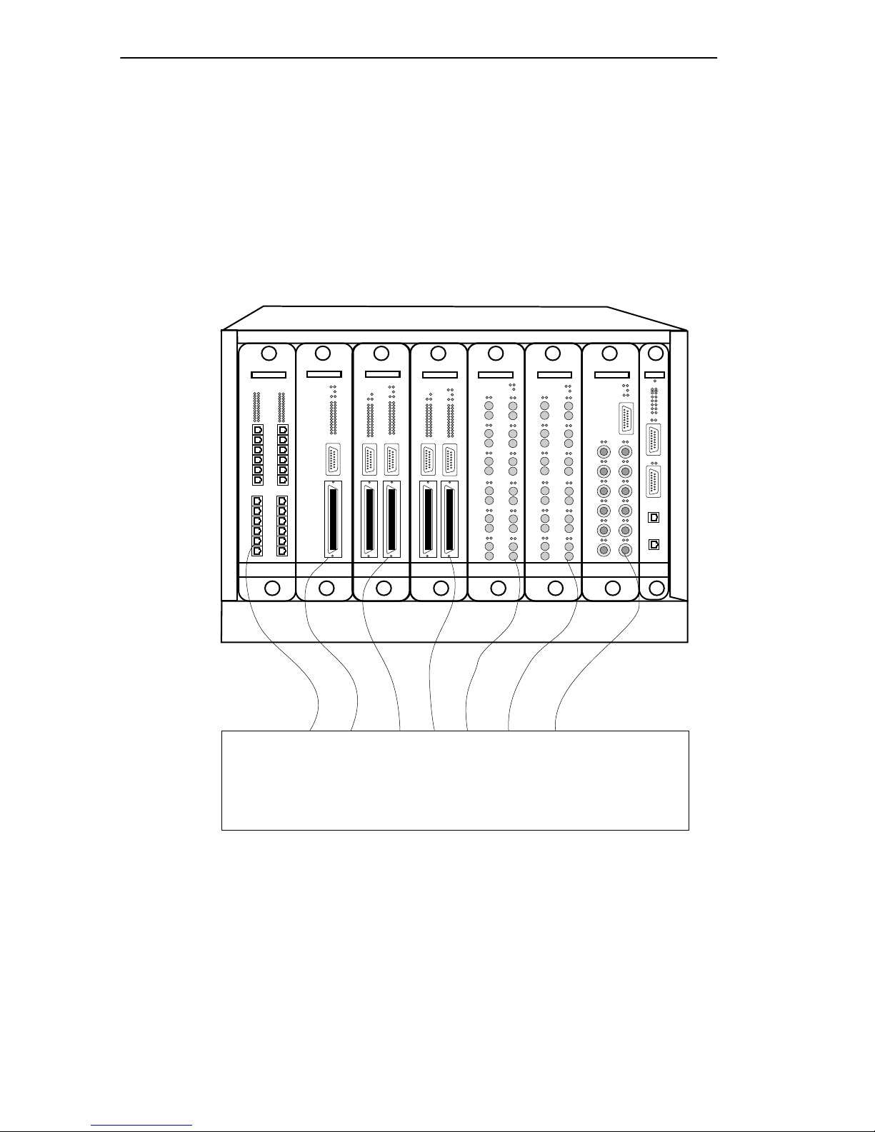
2.4.4 Multiple Routed Sub-Networks
The example in Figure 2-6 illustrates how you can use the EMME to
configure up to seven individual networks in a single MMAC-FNB. This
can be done by connecting each MIM in the MMAC-FNB to a multi-port
router. You can then use the EMME to administratively manage all of the
modules in the hub.
TPMIM-24
TPRMIM-33
TPRMIM-36
TPRMIM-36
EXTERNAL
CXRMIMFORMIM-22FORMIM-22 EMME
Figure 2-6. Configuring Sub-Networks
Page 2-10 EMME USER’S GUIDE
MULTI-PORT
ROUTER
Page 42
SAMPLE NETWORK CONFIGURATIONS
2.4.5 A Fault Tolerant Wiring Hierarchy
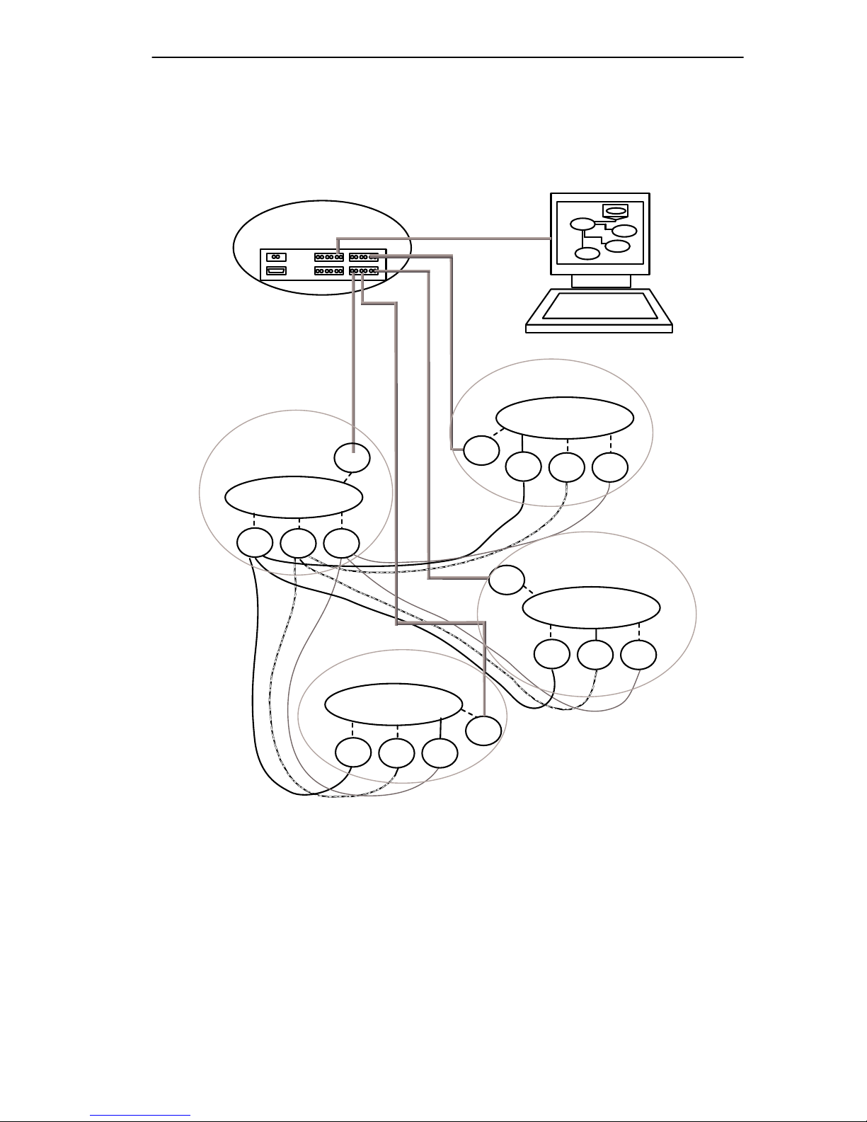
The example in Figure 2-7 illustrates a fault tolerant wiring hierarchy.
Closet D
STAR HUB
BRIDGE
A
B
C
D
Closet A
D
D
D
A
BRIDGE
A
B
Closet B
BRIDGE
C
B
C
B
A
C
Closet C
BRIDGE
D
A
Figure 2-7. Configuring a Fault Tolerant Wiring Scheme
B
C
051439
EMME USER’S GUIDE Page 2-11
Page 43

CHAPTER 2: NETWORK PLANNING AND CONFIGURATION
Closets A, B, and C each contain an MMAC-FNB with an EMME, MIMs
and RIC MIMs operating on Ethernet channels A, B, and C. Within each
closet, each Ethernet channel is separately repeated, and each is dedicated
to a specific set of network users (for example, Ethernet A is dedicated to
administration, Ethernet B to engineering, and Ethernet C to personnel).
The Star Hub, which is an MMAC-FNB that is configured similarly to the
closet hubs, is the central repeater interconnect for the closets, but does
not constitute a single point of failure.
The EMME in each MMAC-FNB utilizes the 802.1d Spanning Tree
Algorithm. By configuring the Root Path Cost and the Bridge Priority on
the EMME, primary paths from each segment can be bridged to Network
D from each EMME (indicated by the solid line between Ethernet
channel A and the bridge in closet A, Ethernet channel B and the bridge in
closet B, and Ethernet channel C and the bridge in closet C). The dotted
lines between the other Ethernet channels and the bridge show the backup
paths in a standby condition. If any repeater link fails, or if an active
bridge path fails, one or many backup bridge paths could become active,
replacing the failed repeater link or bridge path.
An additional level of redundancy is achieved by using the cable
redundancy algorithm built into Cabletron’s EMME. This feature enables
you to configure redundant bridge paths, with one path remaining in
backup, standby mode until the primary path fails.
In the example, Segment D provides a manageable backbone, using a
MiniMMAC. Se gment D provides intercommunication for channels A, B,
and C, as well as serving as the network management segment for the
hierarchy. The individual protocol segments are filtered by the EMME
bridge component, so that the only traffic on segment D is minimal interchannel communication (i.e., mail). Otherwise, only network
management data is on segment D, out-of-band of the traffic on channels
A, B, and C.
Page 2-12 EMME USER’S GUIDE
Page 44

CHAPTER 3
INST ALLING THE EMME
This chapter contains unpacking information and installation instructions
for the Cabletron Systems EMME into a Cabletron Systems
MMAC-FNB. Additional instructions are provided on setting the mode
switches and for connecting segments to the EMME.
3.1 UNP ACKING THE EMME
The contents of the EMME shipment is dependent on whether or not the
EMME was ordered with the Routing software. Table 3-1 lists the items
shipped without the Routing option.
Table 3-1. Items Delivered With EMME
Part Number Description Quantity
9372065 Cable, RJ-45 to RJ-45 1 each
2190183 Download program 1 each
9990050 Disposable wrist strap 1 each
9030514 EMME User’s Guide 1 each
9030834 Release Notes, EMME Boot 1 each
9030746 Release Notes, EMME 1 each
Unpack the EMME as follows:
1. Remove the shipping material covering the EMME in the shipping
box.
2. Carefully remove the module from the shipping box. Leave the
module in its conductive bag until you are ready to install it. Save the
shipping box and materials in the event the unit has to be reshipped.
3. Visually inspect the module. If there are any signs of damage, contact
Cabletron Systems Technical Support immediately.
EMME USER’S GUIDE Page 3-1
Page 45
CHAPTER 3: INSTALLING THE EMME
3.2 SETTING THE EMME MODE SWITCHES
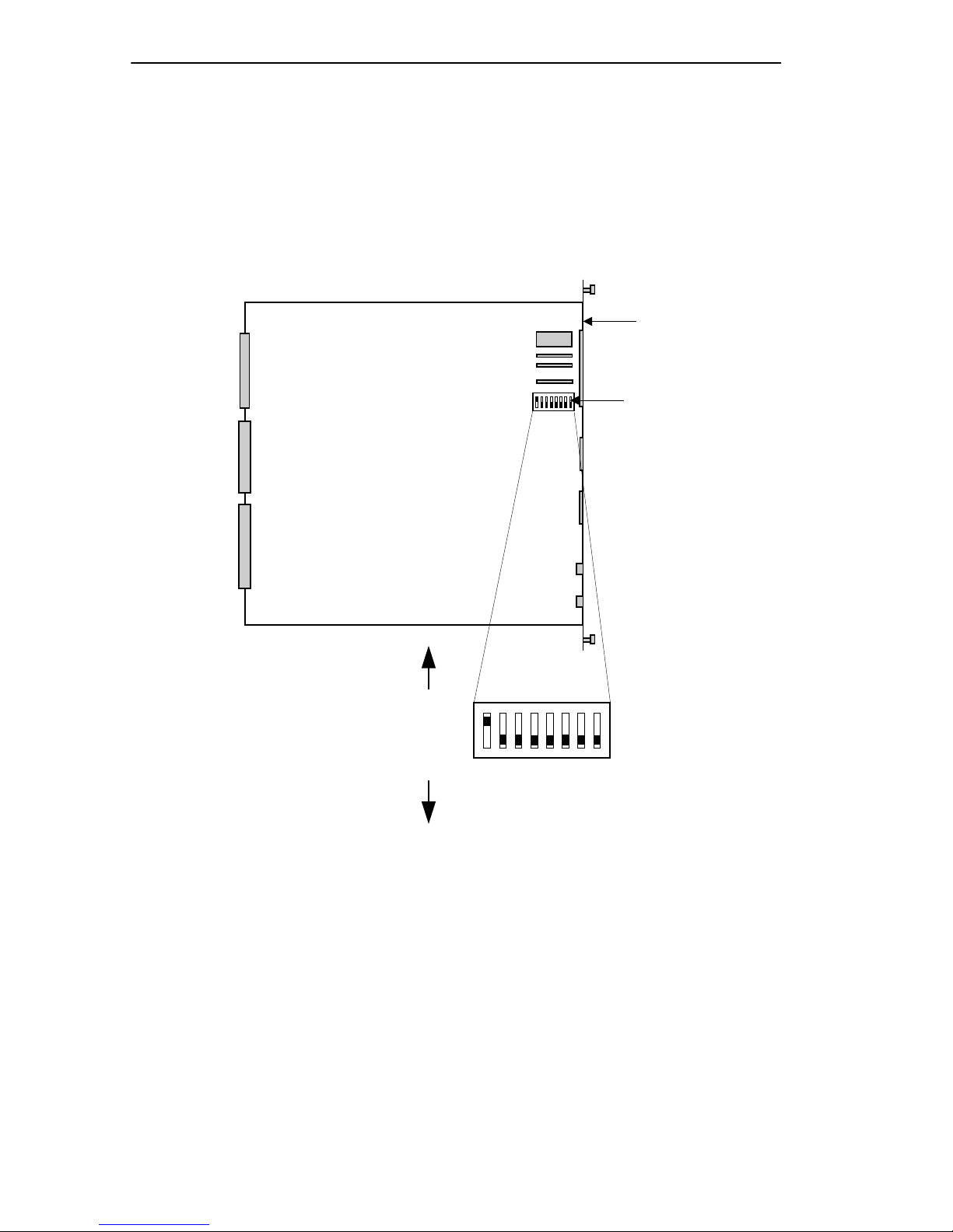
The bank of dip switches located at the top right of the EMME (shown in
Figure 3-1) should be set to their default positions when the module is
shipped. Check these switches to ensure that they are in the correct
position for normal operation of the EMME.
EMME
Switches
On
Off
ON
1 2 3 4 5 6 7 8
Figure 3-1. EMME Dip Switches
051440
Page 3-2 EMME USER’S GUIDE
Page 46

SETTING THE EMME MODE SWITCHES
Switches should be positioned as follows:
Never adjust switch settings on the EMME while there is
WARNING
power applied to it. Slide the EMME out of the chassis and
change the switch as needed to select a function. The
function is initiated when the EMME is reinstalled.
• Switch 1 - NMI (Non-Maskable Interrupt). This switch must be in the
On position. Cabletron Systems use only.
• Switch 2 - STESTDIS (System Test Disable). This switch must be in
the Off position. Cabletron Systems use only.
• Switch 3 - CADIC (Software Debugging T ool). F or manufacturing use
only. Keep in Off position.
• Switch 4 - MIMREV (Management Interface Module Revision). This
switch must be in the Off position for normal operation. Only if you
are using THN-MIM part numbers 9000043-05 and below in your
MMAC-FNB, the switch must be in the On position.
• Switch 5 - Baud Rate Default. Allows you to set the Console port’s
baud rate. The Off position sets the baud rate to 9600. The On position
sets the baud rate to 2400.
• Switch 6 - Forced Download. Changing the position of this switch
after pulling the board out of the MMAC-FNB, clears download
information from NVRAM and forces image files to be downloaded
from the station configured to act as that EMME’s BOOTP server.
EMME USER’S GUIDE Page 3-3
Page 47

CHAPTER 3: INSTALLING THE EMME
Ensure that a BOOTP server has been configured prior to
NOTES
changing the switch 6 position.
When the state of switch 6 is changed, the EMME will begin
requesting a BOOTP server in an attempt to get a flash
image download. The EMME’s BOOT PROM inhibits the
sequence and the EMME requests an IP address and a
filename from the BOOTP server. When received, the
EMME requests a TFTP of the image. The EMME will not
function until the image is downloaded. If the switch 6
position was changed inadvertently and the BootP state is
not desired either press the EMME reset button, cycle the
chassis power, or remove the EMME from the chassis and
reinstall it.
For more information on configuring a station as a BOO TP serv er refer to
the SPECTRUM Element Manager for Windows User’s Manual.
• Switch 7 - NVRAM (Non-Volatile RAM Reset). The EMME uses
NVRAM to store user entered parameters such as IP addresses, device
name, etc. To reset these parameters to the factory defaults, toggle this
switch. Once reset you can use the defaults or re-enter your own
parameters which will be stored in NVRAM when the EMME is
powered down, and remain there until the switch is toggled again.
Do not toggle Switch 7 unless you intend to reset the
!
CAUTION
EMME user parameters to the factory default settings.
• Switch 8 - Password Defaults. When toggled, this switch clears userentered passwords stored in NVRAM, and restores the default
passwords. Once reset you can use the defaults or re-enter your
passwords.
Do not toggle Switch 8 unless you intend to reset the
!
CAUTION
EMME user-configured passwords to their factory default
settings.
Page 3-4 EMME USER’S GUIDE
Page 48

INST ALLING THE EMME
3.3 INST ALLING THE EMME
No special skills or tools are required to install the EMME into an
MMAC-FNB. Use the following guidelines when installing the EMME.
• The EMME must be installed in slot 1 of the MMAC-FNB. (Identified
as the IRM slot in the older MMAC models.)
• When installing the EMME into an MMAC-FNB, be sure that the
MMAC-FNB is properly equipped with a power supply module
(PSM-R) to supply power to the EMME.
• RIC MIMs in an MMAC-FNB series hub should be positioned
contiguously to the EMME, from right to left. This insures that the
channels are not accidentally placed in stand-alone or desegmented
from the B or C channel. This does not apply to shunting
MMAC-FNBs where the data path remains unbroken allowing
communication to continue.
Install the EMME into the MMAC-FNB as follows:
1. Slide the EMME (Figure 3-2) into slot 1 of the MMAC-FNB’s card
cage. (Identified as the IRM slot in the older MMAC models.) Be sure
that the module is properly aligned in the top and bottom slot guides
and firmly press it into the backplane.
2. Secure the module to the MMAC-FNB by turning the knurled knobs.
Be sure that the module is firmly attached to the MMAC-FNB.
For proper seating and operation of the EMME and all
NOTE
MMAC modules, fasten them securely using their front
panel thumbscrews.
3. Power up the MMAC-FNB if it isn’t already on. The LEDs flash and
then extinguish for 30 to 40 seconds. After this period of time, the
BOK LED starts blinking.
EMME USER’S GUIDE Page 3-5
Page 49
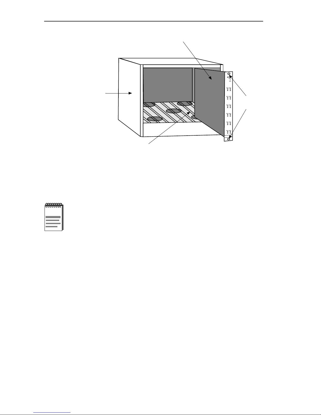
CHAPTER 3: INSTALLING THE EMME
MMAC-M8FNB
Board Slot 2
Repeater MIM
FORMIM22
Knurled
Knobb
051441
Figure 3-2. Installing the EMME
Do not reset the EMME during this time.
NOTE
4. After the system boot procedure, the LEDs should be in the following
conditions:
• BOK LED flashing, indicating that the EMME is operating properly.
• STBY (A, B, C, D) LEDs on or off, depending on the port’ s status after
the Spanning T ree Algorithm has run (Operational-STBY LED OFF or
Blocking-STBY LED ON).
• PWR LEDs lit for the AUI ports, indicating that those ports are
receiving power.
• ON LED lit for the AUI port through which traffic will be passing to,
and from, channel D.
Page 3-6 EMME USER’S GUIDE
Page 50
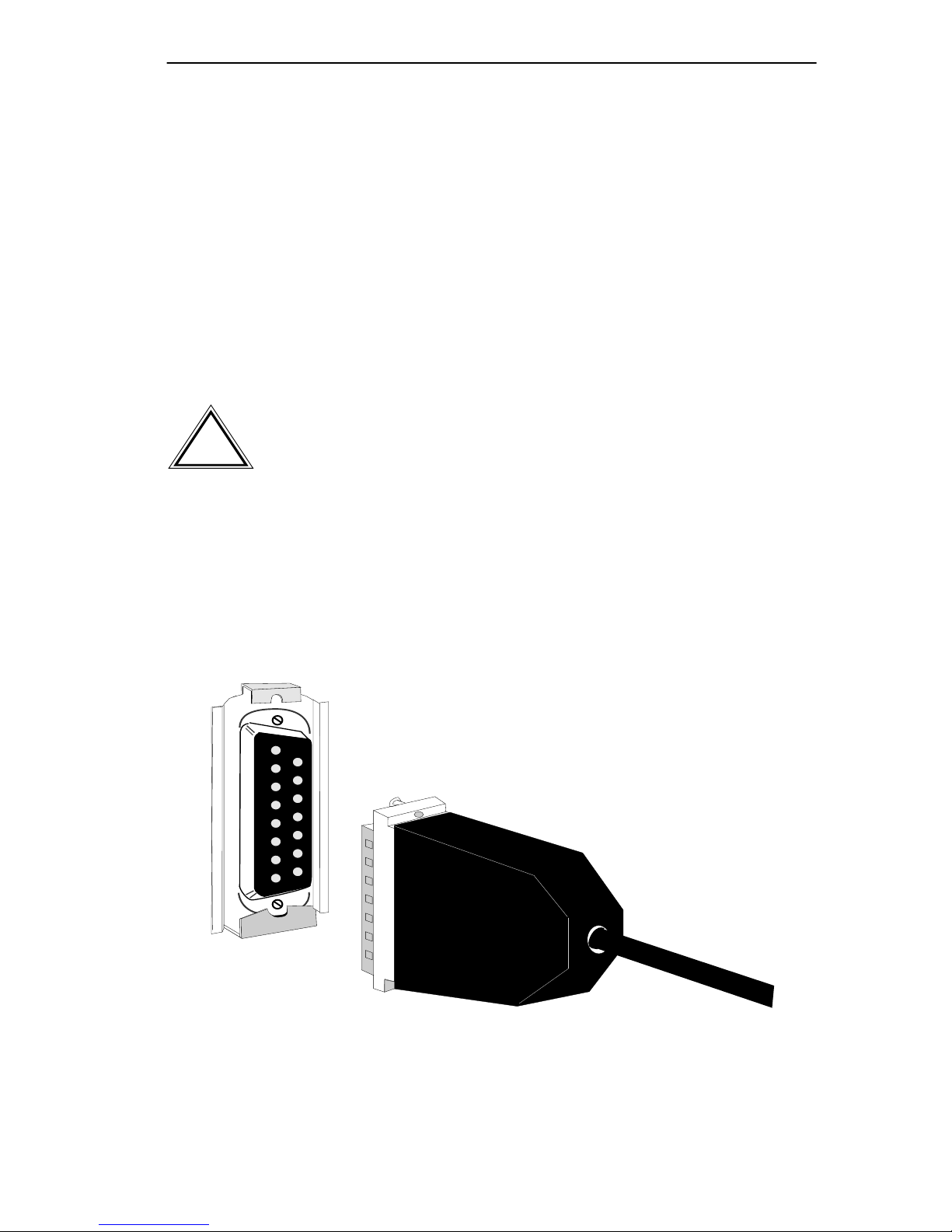
CONNECTING THE EMME TO THE NETWORK
3.4 CONNECTING THE EMME TO THE NETWORK
This section provides procedures for connecting the EMME to the
network via the AUI 1 or AUI 2 port. When the EMME is first powered
up, the AUI 1 port acts as the bridge port and the AUI 2 port is off. To
connect to the network via an AUI port:
1. Attach an external transceiver to the segment to which the AUI
connector will be attached.
2. Attach the female end of an AUI cable, no more than 50 meters in
length,
Make sure to disable the SQE test function on the
!
CAUTION
transceiver that you will be connecting to the EMME’s AUI
port. Failure to do so will result in improper operation of the
EMME. Refer to the applicable transceiver manual.
3. Attach the male connector on the AUI cable (Figure 3-3) to the
appropriate AUI port on the EMME.
4. Move the slide latch on the AUI port to secure it to the lock posts on
the connector.
Figure 3-3. Connecting to the AUI Port
EMME USER’S GUIDE Page 3-7
051442
Page 51

CHAPTER 4
TESTING THE EMME
This chapter contains EMME testing procedures for before and after
making network connections.
4.1 PRE-INST ALLA TION TEST
Before installing the EMME in a live network, test the module in a
controlled situation to insure that it is repeating bridging packets. You can
perform this test with two workstations (Figure 4-1), using an
MMAC-FNB, or MMAC-MFNB, installed with an EMME and a Media
Interface Module (MIM) as follows:
1. Install the EMME and a MIM (TPMIM, THN-MIM, FOMIM,
CXRMIM, FORMIM, etc.) into a stand-alone MMAC-FNB.
2. Connect the first workstation to either the MIM, using the appropriate
cable and transceiver, or to the EMME’s AUI port, using a transceiver
and an AUI cable.
3. Connect the second workstation to the MIM using the appropriate
cable.
4. Set the first workstation as the file server and the second as the client.
(Refer to the workstation manuals for establishing one as a file server
and one as a client. You must assign a valid IP address to the EMME
through Local Management.) Proceed by sending packets between
them to verify that the EMME is operating properly.
If using UNIX workstations, a “ping” test will verify that the
NOTE
EMME is operating properly.
EMME USER’S GUIDE Page 4-1
Page 52
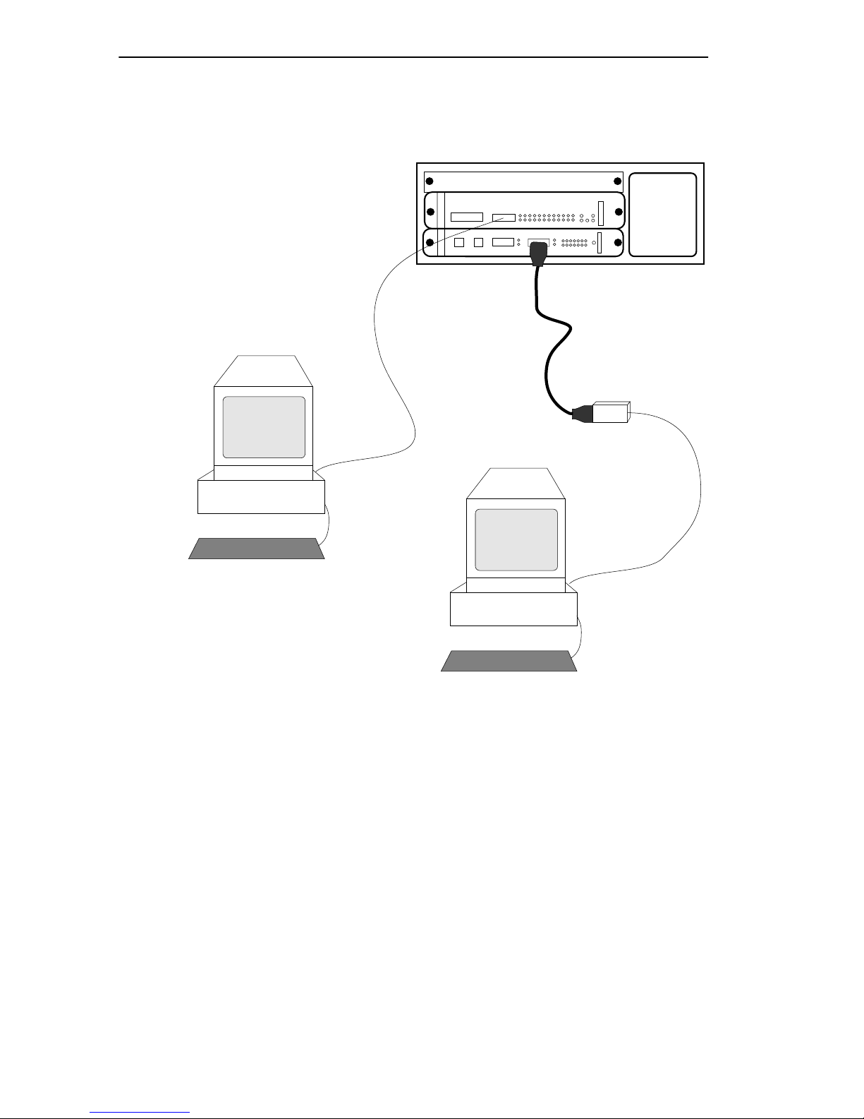
CHAPTER 4: TESTING THE EMME
If a failure occurs, refer to Chapter 7, Troubleshooting.
MMAC3/FNB with EMME and TPRMIM
tTPRMIM-33
EMME
TPT
MMAC-3FNB
Workstation #2
Figure 4-1. Pre-installation Test
Workstation #1
051443
Page 4-2 EMME USER’S GUIDE
Page 53
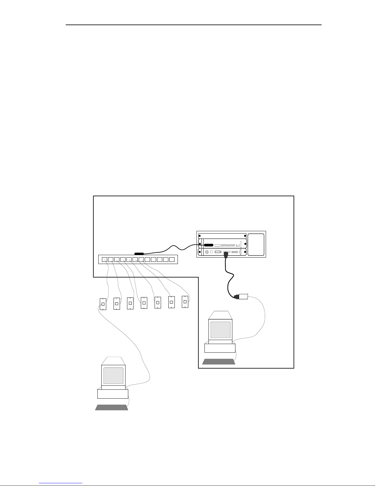
INSTALLATION CHECK-OUT
4.2 INSTALLATION CHECK-OUT
After the EMME is connected to the network, verify that packets can be
passed over the network se gments via the EMME. Again you can use two
workstations set up as file server and client. Keep the server workstation
stationary in the wiring closet with the EMME, and use the client
workstation to move to each node connected to the EMME (Figure 4-2).
1. After the EMME is installed in the MMAC, connect the server
workstation to either a MIM or to the EMME via an AUI port, using a
transceiver and an AUI cable.
2. Sequentially connect a client workstation to each node connected to
the MMAC and proceed to test the segment.
If a failure occurs, refer to Chapter 7, Troubleshooting.
Office Locations
Client Workstation
MMAC3/FNB with EMME and TPRMIM
tTPRMIM-33
MMAC-3FNB
EMME
TPT
File Server Workstation
Figure 4-2. Installation Check-Out Test Configuration
EMME USER’S GUIDE Page 4-3
051444
Page 54

CHAPTER 5
LOCAL MANAGEMENT
This chapter describes how to access and use Local Management for the
EMME. To access Local Management, you need to attach a management
terminal to the EMME’s Console port or establish a Telnet connection
from a station connected to the network.
Local Management for the EMME consists of a series of management
screens that provide tools to manage the EMME and its attached
segments. These tools allow you to perform the following tasks:
• Assign IP addresses and subnet masks to any of the EMME’s four
bridge channels in the four-channel IP routing table.
• Select a default gateway and subnet mask.
• Control access to the EMME by establishing community names.
• Designate which Network Management Workstations receive SNMP
traps from the device.
• Navigate through Management Information Bases (MIBs). Since the
EMME is an SNMP compliant device, you can manage
EMME-related SNMP MIB objects given the appropriate security
level. You can also manage the IETF Bridge MIB objects and many of
the RMON (Remote Monitoring) MIB objects.
This chapter also explains how to attach a cable from an Uninterruptible
Power Supply (UPS) to the EMME, and how to configure the EMME’s
Modem port for the UPS application.
EMME USER’S GUIDE Page 5-1
Page 55

CHAPTER 5: LOCAL MANAGEMENT
5.1 MANAGEMENT TERMINAL CONFIGURA TION
To access Local Management, you need either a VT320 terminal or PC
running VT terminal emulation software.
The following instructions explain how to configure a terminal to
communicate with Local Management. Refer to the terminal’s user guide
for more instructions if necessary. To access the set-up directory on a
VT320 terminal, press F3 (Table 5-1 lists the directory selections).
Table 5-1. VT320 Set-Up Directory Selections
Display Set-up
Columns –>
Controls –>
Auto Wrap –>
Scroll –>
Text Cursor –>
Cursor Style –>
Mode –>
ID Number –>
Cursor Keys –>
Power Supply –>
Communication Set-up
Transmit –>
Receive –>
XOFF –>
Bits –>
Parity –>
Stop Bit –>
Local Echo –>
Port –>
Transmit –>
Auto Answerback –>
80 Columns
Interpret Controls
No Auto Wrap
Jump Scroll
Cursor
Underline Cursor Style
General Set-up
VT300, 7 Bit Controls
VT320ID
Normal Cursor Keys
UPS DEC Supplemental
Transmit=9600
Receive=Transmit
XOFF at 64
8 bits
No Parity
1 Stop Bit
No Local Echo
DEC-423, Data Leads Only
Limited Transmit
No Auto Answerback
Keys –>
Auto Repeat –>
Keyclick –>
Margin Bell –>
Warning Bell –>
Page 5-2 EMME USER’S GUIDE
Keyboard Set-Up
Typewriter Keys
any option
any option
Margin Bell
Warning Bell
Page 56

MANAGEMENT TERMINAL CONFIGURATION
5.1.1 Cable Configuration for the Management Terminal
This section outlines the proper cable configurations to connect a
management terminal to the Console port of the EMME. For information
on the appropriate pinouts, refer to Appendix C.
You need an adapter kit containing the following items to connect a
terminal to the EMME Console port:
• An RS232 cable
• An adapter
• A device cable
The adapter you use depends on whether you connect a VT320 terminal
or a PC emulating a VT320 to the EMME Console port. Read the
information included with the adapter kit to make sure that you are using
the correct adapter.
To configure the cables, perform the following steps:
1. Plug a straight-through twisted pair cable (e.g., an RS232 cable) into
the EMME’s RJ45 Console port.
2. Plug the other end of the RS232 cable into the adapter.
3. Connect the adapter into the device cable and plug the other end of the
device cable into the terminal.
4. Power on the terminal. Access to Local Management is automatic.
EMME USER’S GUIDE Page 5-3
Page 57

CHAPTER 5: LOCAL MANAGEMENT
5.1.2 Cable Configuration for the UPS
To configure a cable from the Uninterruptible Power Supply (UPS) to the
EMME perform the following steps:
1. Plug a straight-through twisted pair, RS232, cable into the EMME
RJ45 Modem port.
2. Plug the other end of the RS232 cable into the adapter (Part No.
9372066) and connect the adapter to the UPS.
After the cable configuration is complete, use one of the following
management tools to configure the EMME Modem port for UPS
application:
• EMME Local Management – The System Level Screen section of this
chapter provides instructions for setting up the EMME Modem port
for the UPS application.
• Graphical user interfaces provided by SPECTRUM Element Manager
for Windows, SPECTRUM Portable Management Applications
(SPMAs), or SPECTRUM software packages.
5.2 ESTABLISHING A TELNET CONNECTION
Once the EMME has a valid IP address, you can establish a Telnet session
with Local Management from any TCP/IP based node on the network.
T elnet connections to the EMME require the community name passw ords
assigned at the SNMP Community Names screen. Refer to the SNMP
Community Names section of this manual for additional information
about community names.
See the instructions included with the Telnet application for
NOTE
information about establishing a Telnet session.
Page 5-4 EMME USER’S GUIDE
Page 58

LOCAL MANAGEMENT KEYBOARD CONVENTIONS
5.3 LOCAL MANA GEMENT KEYBOARD CONVENTIONS
All key names appear in this manual as capital letters. For example, the
Enter key appears as ENTER, the Escape Key appears as ESC, and the
Backspace Key appears as BACKSPACE. Table 5-2 explains the
keyboard conventions used in this manual as well as the key functions.
Table 5-2. Keyboard Conventions
Key Function
ENTER Key and RETURN Key These are selection keys that
perform the same Local
Management function. For
example, “Press ENTER” means
that you can press either ENTER
or RETURN, unless this manual
specifically instructs you
otherwise.
ESCAPE (ESC) Key This key lets you escape from a
Local Management screen
without saving your changes. For
example, “Press ESC twice”
means that you must quickly
press the ESC key two times.
SPACEBAR and BACKSPACE
Key
Arrow Keys These are navigation keys. Use
These keys cycle through
selections in some Local
Management fields. Use the
SPACEBAR to cycle forward
through selections and use
BACKSPACE to cycle backward
through selections.
the UP-ARROW,
DOWN-ARRROW,
LEFT-ARROW, and
RIGHT-ARROW k e ys to mo v e the
screen cursor. For example, “Use
the arrow keys” means to press
whichever arrow key moves the
cursor to the desired field on the
Local Management screen.
EMME USER’S GUIDE Page 5-5
Page 59

CHAPTER 5: LOCAL MANAGEMENT
Table 5-2. Keyboard Conventions (Continued)
SHIFT + [+] Keys This key combination increments
values in a Local Management
increment field. For example,
“Press SHIFT + [+]” means to
hold down the SHIFT key while
pressing the plus sign key.
[–] Key This key decreases v alues from a
Local Management increment
field. For example, “Press [–]”
means to press the minus sign
key.
DEL Key The DEL (Delete) key removes
characters from a Local
Management field. For example,
“Press DEL” means to press the
Delete key.
Page 5-6 EMME USER’S GUIDE
Page 60

ACCESSING LOCAL MANAGEMENT
5.4 ACCESSING LOCAL MANAGEMENT
Verify that your terminal has been properly connected to the EMME
before proceeding.
To access Local Management, perform the following steps:
1. Power on the terminal. The EMME Password screen, Figure 5-1,
appears.
EMME Local Management
CABLETRON Systems, Incorporated
35 Industrial Way, P.O.Box 5005
Rochester, NH 03867-0505 USA
(603) 332-9400
(c) Copyright CABLETRON Systems, Inc, 19XX
Flash Image Version:
Boot EPROM Version:
Board Revision:
Enter USER PASSWORD:
XX.XX.XX
XX.XX.XX
XX
Figure 5-1. The EMME Password Screen
051445
EMME USER’S GUIDE Page 5-7
Page 61

CHAPTER 5: LOCAL MANAGEMENT
2. Enter your Password and press ENTER. The default super-user access
password is “public” or press ENTER.
Your password is one of the community names specified in
NOTE
the SNMP Community Names screen. Access to certain
Local Management capabilities depends on the degree of
access accorded that community name. See the SNMP
Community Names section.
• If an invalid password is entered the terminal beeps and the cursor
returns to the beginning of the password entry field.
• Entering a valid password causes the associated access lev el to display
at the bottom of the screen and the Main Menu screen, Figure 5-3,
appears.
If no activity occurs for several minutes the Password screen reappears
and the password will have to be re-entered.
Page 5-8 EMME USER’S GUIDE
Page 62

NAVIGATING LOCAL MANAGEMENT SCREENS
5.5 NAVIGATING LOCAL MANAGEMENT SCREENS
EMME Local Management consists of a series of menu screens. You
navigate through Local Management by selecting items from the menu
screens. EMME Local Management consists of the following menu
screens:
• Main Menu screen
• Setup Menu screen
• Status Menu screen
Figure 5-2 shows the hierarchy of Local Management screens.
System Level
Setup Menu
SNMP Community Names
SNMPTraps
Main MenuPassword
Status Menu Component Status
Device Statistics
MIB Navigator
051455
Figure 5-2. Hierarchy of Local Management Screens
5.5.1 Selecting Local Management Menu Screen Items
To Select items on a Local Management menu screen, perform the
following steps:
1. Use the arrow keys to highlight a menu item.
2. Press ENTER. The selected menu item appears on the screen.
EMME USER’S GUIDE Page 5-9
Page 63

CHAPTER 5: LOCAL MANAGEMENT
5.5.2 Exiting Local Management Screens
To exit any of the Local Management screens, perform the following
steps:
1. Use the arrow keys to highlight the RETURN command at the bottom
of the Local Management screen.
2. Press ENTER. The previous screen in the Local Management
hierarchy appears.
You can also exit Local Management screens by pressing
NOTE
3. To Exit from EMME Local Management, repeat steps 1 and 2 until the
Main Menu screen appears.
ESC twice. This exit method does not warn you about
unsaved changes and all unsaved changes will be lost.
4. Use the arrow keys to highlight the EXIT command at the bottom of
the Main Menu screen.
5. Press ENTER. The EMME Local Management Password screen
appears and the Local Management session ends.
Page 5-10 EMME USER’S GUIDE
Page 64

THE MAIN MENU SCREEN
5.6 THE MAIN MENU SCREEN
The Main Menu screen is the starting point from which all the Local
Management screens are accessed. Figure 5-3 shows the Main Menu
screen.
Event Message Line
EMME Local Management
MAIN MENU
SETUP MENU
STATUS MENU
DEVICE STATISTICS
MIB NAVIGATOR
Flash Image Version: XX.XX.XX
EXIT
051446
Figure 5-3. The Main Menu
The Main Menu screen displays the following menu items:
• SETUP MENU - The Setup Menu provides access to Local
Management screens that are used to configure the EMME.
• STATUS MENU - The Status Menu provides access to the
Component Status screen which displays the operational and
administrative status of EMME MIB components.
• DEVICE STATISTICS - The Device Statistics screen provides
statistics and performance information for devices managed by the
EMME in the network.
• MIB NAVIGATOR - The MIB Navigator is a Local Management
utility which allows the user to access, monitor, and set specific
Management Information Base (MIB) items within the EMME.
Chapter 6 explains how to use the MIB Navigator utility.
EMME USER’S GUIDE Page 5-11
Page 65

CHAPTER 5: LOCAL MANAGEMENT
5.7 SETUP MENU SCREEN
The Setup Menu provides access to Local Management screens that are
used to configure or alter the configuration of the EMME. Examples of
functions accessible through the Setup Menu include configuring IP
addresses and subnet masks, assigning SNMP community names, and
configuring SNMP trap notification. Figure 5-4 shows the Setup Menu.
Event Message Line
EMME Local Management
SETUP MENU
SYSTEM LEVEL
SNMP COMMUNITY NAMES
SNMP TRAPS
Flash Image Version XX.XX.XX
RETURN
051447
Figure 5-4. The Setup Menu
The Setup Menu displays the following menu items:
• SYSTEM LEVEL - The System Level Setup screen allows you to
configure basic operating parameters for the EMME.
• SNMP COMMUNITY NAMES - The SNMP Community Names
Setup screen allows you to change or review the community names
used as access passwords for local management operation.
• SNMP TRAPS - The SNMP T raps Setup screen provides display and
configuration access to the table of IP addresses used for trap
destinations and associated community names.
Page 5-12 EMME USER’S GUIDE
Page 66

THE SYSTEM LEVEL SCREEN
5.8 THE SYSTEM LEVEL SCREEN
Figure 5-5 shows the EMME System Level screen. This screen allows
you to configure the following parameters:
• System Date and System Time
• IP Addresses, Subnet Masks, and Default Gateway
• Default Interface
• Console and Modem port applications
Event Message Line
EMME Local Management
SYSTEM LEVEL
Flash Image Version XX.XX.XX
14:23:00System Time:System Date: 12/30/95
Channel
I/F
1
2
3
4
Console Application:
Modem Application:
SAVE
A
B
C
D
Default Interface
IP Address
000.000.000.000
000.000.000.000
000.000.000.000
000.000.000.000
01
[LM]
[UPS]
Subnet Mask
255.255.0.0
255.255.0.0
255.255.0.0
255.255.0.0
Default Gateway
MAC Address
00-00-1D-07-50-0E
00-00-1D-07-50-0F
00-00-1D-07-50-10
00-00-1D-07-50-11
0.0.0.0
Figure 5-5. The System Level Screen
5.8.1 System Level Screen Fields
The following briefly explains each System Level screen field.
RETURN
051448
System Date - Displays the system date.
System Time - Displays the system time.
I/F - Displays the number of the interface corresponding to the channel
over which packets with that IP address are passing.
EMME USER’S GUIDE Page 5-13
Page 67

CHAPTER 5: LOCAL MANAGEMENT
Channel - Shows the channel, or bus, through which pack ets with that IP
address are passing. Channel A is the original Ethernet bus channel.
Channels B & C are the Flexible Network Bus channels. Channel D is the
external Ethernet network accessed through an AUI port. Refer to Chapter
1 for a more complete description about channels.
IP Address - Displays the IP address of each of the four EMME
interfaces.
Subnet Mask - Displays the subnet mask for each of the four EMME
channels. A subnet mask “masks out” the network bits of the IP address
by setting the bits in the mask to 1 when the network treats the
corresponding bits in the IP address as part of the network or subnetwork
address, or to 0 if the corresponding bit identifies the host.
MA C Address - Displays the physical address of each bridge interface.
Default Interface - Displays the default interface for the EMME’ s default
gateway. The default interface is the channel that is set up to handle
message traffic to external networks. This field defaults to four.
Default Gateway - Displays the default gateway for the EMME. This
should be the IP address of a perimeter or border device that connects
your network to the rest of the world. The border de vice can be any de vice
that is suitable for interfacing with external message traffic. This field is
not defined until an appropriate value is entered.
Console Application - Displays the Console port’s application setting as
UNASSIGNED, SLIP, UPS, or LM.
Modem Application - Displays the Modem port’s application setting as
UNASSIGNED, SLIP, UPS, or LM.
Baud Rate - (This field only appears when the Console Application or the
Modem Application is set to SLIP) - Displays the Baud Rate setting of the
device attached to the EMME through the CONSOLE or MODEM port.
The settings for this field are 19200, 9600, 4800, 2400, 1200, 600, and
300. The default setting is 9600.
Page 5-14 EMME USER’S GUIDE
Page 68

THE SYSTEM LEVEL SCREEN
5.8.2 Setting the System Date
To set the system date, perform the following steps:
1. Use the arrow keys to highlight the System Date field.
2. Enter the date in a MM/DD/YY format.
When entering the date in the system date field, you do not
NOTE
3. Press ENTER to set the system calender to the date in the input field.
4. Use the arrow keys to highlight the SAVE command at the bottom of
the screen and press ENTER.
need to add any separators between month, day, and year
numbers, as long as each entry uses two decimal numbers.
For example, to set the date to 03/17/96, type “031796” in
the System Date field.
If the date entered was a valid format, the Event Message Line at the top
of the screen displays “SAVED OK.” If the entry was not valid, Local
Management does not alter the current value and refreshes the System
Date field with the previous value.
5.8.3 Setting the System Time
To set the system clock, perform the following steps:
1. Use the arrow keys to highlight the System Time field.
2. Enter the time in a 24-hour format, HH:MM:SS.
When entering the time in the system time field, you do not
NOTE
need to add any separators between hours, minutes, and
seconds, as long as each entry uses two decimal numbers.
For example, to set the time to 6:45 a.m., type “064500” in
the System Time field.
3. Press ENTER to set the system clock to the time in the input field.
EMME USER’S GUIDE Page 5-15
Page 69

CHAPTER 5: LOCAL MANAGEMENT
4. Use the arrow keys to highlight the SAVE command at the bottom of
the screen and press ENTER.
If the time entered was a valid format, the Event Message Line at the top
of the screen displays “SAVED OK.” If the entry was not valid, Local
Management does not alter the current value and refreshes the System
Time field with the previous value.
5.8.4 Setting the IP Address
The IP Address table allo ws you to assign IP addresses to each of the four
EMME interfaces. These four interfaces keep the packet traffic between
devices for a specific channel’s subnetwork on that subnetwork, and only
forwards packets meant for devices on another channel and its related
subnetwork(s). This increases the number of segments that can be
connected to one EMME-controlled FNB supporting MMAC.
Before you configure the IP Address Table, check that your configuration
correctly establishes your repeater MIMs for either Channel B, C, or as
stand-alones (refer to your repeater MIM documentation if necessary).
To set the EMME IP address, perform the following steps;
1. Use the arrow keys to highlight the appropriate IP address field.
2. Enter the IP address into this field using Decimal Dotted Notation
(DDN) format.
For example: 134.141.25.17
3. Press ENTER. If the IP Address entered was a valid format, the cursor
returns to the beginning of the IP Address field. If the entry was not
valid, the Event Message Line displays “INVALID IP ADDRESS OR
FORMAT ENTERED.” Local Management does not alter the current
value and refreshes the IP Address field with the previous value.
4. Repeat steps 1–3 to enter each Interface’s IP address.
5. Use the arrow keys to highlight the SAVE command.
6. Press ENTER. The Event Message Line at the top of the screen
displays “SAVED OK.”
Page 5-16 EMME USER’S GUIDE
Page 70

THE SYSTEM LEVEL SCREEN
5.8.5 Setting the Subnet Mask
If the management workstation that will be receiving SNMP traps from
the SNMP agent of the managed device is located on a separate subnet,
the subnet mask for the managed device must be changed from its default.
To change the subnet mask from its default value, perform the following
steps:
1. Use the arrow keys to highlight the appropriate Subnet Mask field.
2. Enter the subnet mask into this field using Decimal Dotted Notation
(DDN) format.
For example: 255.255.0.0
3. Press ENTER. If the subnet mask entered was a valid format, the
cursor returns to the beginning of the Subnet Mask field. If the entry
was not valid, the Event Message Line displays “INVALID SUBNET
MASK OR FORMAT ENTERED.” Local Management does not alter
the current value and refreshes the Subnet Mask field with the
previous value.
4. Repeat steps 1 - 3 for each interface’s subnet mask.
5. Use the arrow keys to highlight the SAVE command.
6. Press ENTER. The Event Message Line at the top of the screen
displays “SAVED OK.”.
5.8.6 Setting the Default Interface
The default interface should be set to reflect the interface channel for the
designated default gateway. To set the Default Interface, perform the
following steps:
1. Use the arrow keys to highlight the Default Interface field.
2. Enter the interface number for the default gateway in this field with a
value from 1 to 4.
EMME USER’S GUIDE Page 5-17
Page 71

CHAPTER 5: LOCAL MANAGEMENT
3. Press ENTER. If the subnet mask entered was a valid format, the
cursor returns to the beginning of the Subnet Mask field. If the entry
was not valid, the Event Message Line displays “PERMISSIBLE
RANGE: 1...4.” Local Management does not alter the current value
and refreshes the Default Interface field with the previous value.
4. Use the arrow keys to highlight the SAVE command.
5. Press ENTER. The Event Message Line at the top of the screen
displays “SAVED OK.”.
5.8.7 Setting the Default Gateway
If the SNMP management station is located on a different IP subnet than
the managed device, a default gate way must be specified. When an SNMP
Trap is generated, the device will send it to both the Management station
and the default gateway. To set the default gate way, perform the following
steps:
1. Use the arrow keys to highlight the Default Gateway field.
2. Enter the IP address of the default gateway. IP address entries must
follow the DDN format.
For example: 134.141.79.121
3. Press ENTER. If the default gateway entered was a valid format, the
cursor returns to the beginning of the Default Gateway field. If the
entry was not valid, the Event Message Line displays “INVALID
DEFAULT GATEWAY OR FORMAT ENTERED.” Local
Management does not alter the current value and refreshes the Default
Gateway field with the previous value.
4. Use the arrow keys to highlight the SAVE command.
5. Press ENTER. The Event Message Line at the top of the screen
displays “SAVED OK.”
Page 5-18 EMME USER’S GUIDE
Page 72

THE SYSTEM LEVEL SCREEN
5.8.8 Configuring Console and Modem Ports
The EMME Console and Modem ports support the following
applications:
Refer to the Release Notes included with the EMME to
NOTE
• Local Management connections
• American Power Conversion (APC) Uninterruptible Power Supply
(UPS) connections
• T elnet connections to a wide area network via the Serial Line Internet
Protocol (SLIP)
verify which Console and Modem Port applications are
currently supported.
• Unassigned applications for security reasons.
To configure the Console and Modem ports, perform the following steps:
1. Use the arrow keys to highlight the Console Application or the Modem
Application field.
Use caution not to alter the settings of the port which is
WARNING
operating the current Local Management connection. This
could disconnect the Local Management terminal from the
port and end the Local Management session.
EMME USER’S GUIDE Page 5-19
Page 73

CHAPTER 5: LOCAL MANAGEMENT
2. Press SPACEBAR or BACKSPACE to cycle through the available
settings until the operation you require appears. Table 5-3 lists the
available settings and their corresponding applications.
Table 5-3. COM Port Application Settings
Setting Application
[LM] Local Management Session
[UPS] APC Power Supply SNMP Proxy
[SLIP] Serial Line Internet Protocol
[UNASSIGNED] Not Active
3. Press ENTER to accept the application.
If the SLIP application is chosen for the port, an additional field will
appear to the right of the port field. This is the Baud Rate field. The Baud
Rate field allows the port operating SLIP to be set to the correct baud rate
for its modem connection.
To alter and set the SLIP baud rate, perform the following steps:
1. Use the arrow keys to highlight the COM X Baud Rate field.
2. Press SPACEBAR or BACKSPACE cycle through the available baud
rates for SLIP operation.
The Console port and Modem port support standard baud
NOTE
rates between 300 and 19,200.
3. Press ENTER to select the desired baud rate.
4. Use the arrow keys to highlight the SAVE command.
5. Press ENTER. The Event Message Line at the top of the screen
displays “SAVED OK.”
Page 5-20 EMME USER’S GUIDE
Page 74

SNMP COMMUNITY NAMES SCREEN
5.9 SNMP COMMUNITY NAMES SCREEN
Figure 5-6 shows the SNMP Community Names screen. The network
manager may control Local Management access by establishing three (3)
passwords. Each password controls varying levels of access to EMME
Local Management.
Event Message Line
EMME Local Management
SNMP COMMUNITY NAMES
Flash Image Version: XX.XX.XX
Community Name
public
public
public
SAVE RETURN
Access Policy
read-only
read-write
super-user
Figure 5-6. The Community Names Screen
The following list describes each of the three levels of access:
051449
• super-user: Allows full management privileges
• read-write: Allows edit of some device configuration parameters not
including changing community names
• read-only: Allows reading of device parameters not including
community names
In order to perform any operations on the SNMP Community Names
screen, the user must have used the super-user community name at the
User Password prompt when initiating the Local Management session.
EMME USER’S GUIDE Page 5-21
Page 75

CHAPTER 5: LOCAL MANAGEMENT
5.9.1 Setting SNMP Community Names
To set a community name, perform the following steps:
1. Use the arrow keys to highlight the community name you want to
change.
2. Type the new community name and press ENTER. The old
community name text will disappear and be replaced by the new
community name.
3. Use the arrow keys to highlight the SAVE command.
4. Press ENTER. The Event Message Line at the top of the screen
displays “SAVED OK.”
If you edit the super-user community name, be certain you
WARNING
do not forget it. If you do, you will be unab le to perf orm Local
Management functions without returning the device to its
factory default configurations. This will effectively erase any
configuration work you may have done.
Page 5-22 EMME USER’S GUIDE
Page 76

SNMP TRAPS SCREEN
5.10 SNMP TRAPS SCREEN
Figure 5-7 shows the SNMP Traps screen. Configuring the SNMP Traps
screen allows the EMME to send SNMP Traps to multiple network
management stations. The following sections explain SNMP Trap screen
information fields as well as providing instructions for configuring them.
Event Message Line
EMME Local Management
0.0.0.0
0.0.0.0
0.0.0.0
0.0.0.0
0.0.0.0
0.0.0.0
0.0.0.0
0.0.0.0
SNMP TRAPS
Trap Community NameTrap Destination Enable Traps
public
public
public
public
public
public
public
public
Flash Image Version: XX.XX.XX
(NO)
(NO)
(NO)
(NO)
(NO)
(NO)
(NO)
(NO)
SAVE
RETURN
051450
Figure 5-7. The SNMP Traps Screen
5.10.1 Trap Table Screen Fields
SNMP Community Name - Displays the Community Name to be
included in the trap message sent to the Network Management Station
with the associated IP address.
Traps - Enables transmission of the traps to the network management
station with the associated IP address.
Trap IP Address - Indicates the IP address of the workstation to receive
trap alarms from the EMME.
EMME USER’S GUIDE Page 5-23
Page 77

CHAPTER 5: LOCAL MANAGEMENT
5.10.2 Setting SNMP Trap Destinations
To set SNMP Trap destinations using Local Management requires three
distinct operations: the configuration of a destination address for the traps
to be sent to, the assignment of a community name for that IP address,
and the enabling of the combination of IP address and community name.
To set an SNMP trap destination, perform the following steps:
1. Use the arrow keys to highlight the Trap Destination input field you
wish to modify.
2. Type the IP address of the management station to which you want
SNMP traps to be sent. This address must be entered in DDN format.
3. Press ENTER.
4. Use the arrow keys to highlight the corresponding Trap Community
Name input field (on the same row as the Trap Destination field).
5. Type the community name into the input field that you intend the
management station to use for accessing SNMP traps and performing
management operations.
6. Press ENTER.
7. Use the arrow keys to highlight the Enable Traps field (on the same
row as the Trap Destination and Trap Community Name you have just
configured). By default, this toggle item will be [NO].
8. Press SPACEBAR or BACKSPACE to set the toggle field to [YES].
9. Use the arrow keys to highlight the SAVE command.
10. Press ENTER. The Event Message Line at the top of the screen
displays “SAVED OK.”
Page 5-24 EMME USER’S GUIDE
Page 78

STATUS MENU
5.11 STATUS MENU
Figure 5-8 shows the Status Menu screen. The Status Menu screen
provides access to the Component Status screen.
Event Message Line
EMME Local Management
STATUS MENU
COMPONENT STATUS
Flash Image Version: XX.XX.XX
Figure 5-8. The Status Menu Screen
RETURN
051451
EMME USER’S GUIDE Page 5-25
Page 79

CHAPTER 5: LOCAL MANAGEMENT
5.12 THE COMPONENT STATUS SCREEN
Figure 5-9 shows the Component Status screen. The Component Status
screen monitors the status of the MIB Components of the EMME.
Event Message Line
EMME Local Management
Component Name Admin. Status
EMME Chassis MGR enabled
EMME LIM enabled
Ctron Use Only enabled
EMME Host Services enabled
EMME IP Services enabled
EMME Distributed LAN Monitor enabled
EMME MIB Navigator enabled
EMME RMON Default disabled
EMME RMON Host disabled
EMME RMON Capture disabled
EMME Transparent Bridge enabled
COMPONENT STATUS
Flash Image Version: XX.XX.XX
RETURN
051452
Figure 5-9. The Component Status Screen
5.12.1 Component Status Screen Fields
The Component Status table lists the Admin. Status (administrative
status) of the EMME’s MIB Components. The Admin. Status field
displays two states: Enabled and Disabled. Refer to Figure 5-9 for a list of
the EMME’s MIB Component Names.
Page 5-26 EMME USER’S GUIDE
Page 80

THE DEVICE STATISTICS SCREEN
5.13 THE DEVICE STATISTICS SCREEN
Figure 5-10 shows the Device Statistics screen. The Device Statistics
screen displays error, collision, and traf fic statistics for the entire network,
a selected slot, or a selected port. This screen also provides the option of
enabling and disabling ports.
EMME Local Management
Cabletron EMME Revision xx.xx.xx
DEVICE STATISTICS
NETWORK: D
BYTES RECEIVED:
FRAMES RECEIVED:
FRAMES FILTERED:
FRAMES TRANSMITTED:
ERRORS RECEIVED:
COLLISIONS:
OOW COLLISIONS:
CRC ERRORS:
ALIGNMENT ERRORS:
RUNT PACKETS:
GIANT PACKETS:
PORT ADMIN. ST A TUS:
PORT SEG. STATUS:
UPDATE-FREQ 3 Sec NETWORK D SLOT 1 PORT 1 RETURN
ENABLE PORT DISABLE PORT
0
0
0
0
0
0
0
0
0
0
0
SLOT: 1
PORT: 1
FORWARDING
Figure 5-10. Device Statistics Screen
051453
5.13.1 Device Statistics Screen Fields
The following sections describe Device Statistics Screen fields and
instructions on how to change them.
BYTES RECEIVED - Displays the number of bytes received.
FRAMES RECEIVED - Displays the number of frames received.
FRAMES FILTERED - Displays the number of frames filtered by the
EMME.
FRAMES TRANSMITTED - Displays the number of frames
transmitted by the EMME.
ERRORS RECEIVED - Displays the number of errors received.
EMME USER’S GUIDE Page 5-27
Page 81

CHAPTER 5: LOCAL MANAGEMENT
COLLISIONS - Displays the number of collisions received.
OOW COLLISIONS - Displays the number of Out Of Window (OOW)
collisions. OOW collisions are usually caused by the network being too
long where the round trip propagation delay is greater than 51.2 µs (the
collision domain is too large), a station somewhere on the network is
violating Carrier Sense and transmitting at will, or a cable somewhere on
the network failed during the transmission of the packet.
CRC ERRORS - Displays the number of packets with bad Cyclic
Redundancy Checks (CRC) that have been received from the network.
The CRC is a 4-byte field in the data packet which ensures that the
transmitted data received is the same as the data that was originally sent.
ALIGNMENT ERRORS - Displays the number of errors due to
misaligned packets.
RUNT PACKETS - Displays the number of runt packets received from
the network. A runt packet is less than the minimum Ethernet frame size
of 64 bytes, not including preamble.
GIANT PACKETS - Displays the number of packets received whose
size exceeded 1518 data bytes, not including preamble.
PORT ADMIN. STATUS - Displays the administrative status of the port
selected. The two possible status messages are Enable or Disable.
PORT SEG. STATUS - Displays the segmentation status of the port
selected. The two possible status messages are Segmented or
Unsegmented. The EMME automatically partitions problem segments,
and reconnects non-problem segments to the network.
ENABLE PORT - This command lets you enable the selected port.
DISABLE PORT - This command lets you disable the selected port.
UPDATE-FREQ - This command lets you select the time interval
between Network/Slot/Port counter updates. You can choose update
intervals in increments of 3 seconds, with the maximum interv al being 99
seconds.
Page 5-28 EMME USER’S GUIDE
Page 82

THE DEVICE STATISTICS SCREEN
NETWORK - This command lets you select the network you want to
monitor. The choices range from A to D, depending on the configuration
of your network and the options available from this configuration. For
example, if you do not have a device running on Channel A, the EMME
automatically disallows Channel A as a network selection.
SLOT - This command lets you select the MMAC hub slot that you want
to monitor. The choices vary depending on the MMAC chassis you use.
The far right slot is always slot number one (1).
PORT - This command lets you select and view port statistics for ports 1
through 26 of the device residing in the selected slot.
5.13.2 Selecting an Update-Freq
The EMME updates the Device Statistics Screen every three seconds by
default. The EMME allows you to adjust the frequency in intervals of 3
seconds. The maximum update frequency is 99 seconds.
To adjust the Update-Freq, perform the following steps:
1. Use the arrow keys to highlight the Update-Freq command.
2. Press SHIFT+[+], or [–] until the desired time/frequency appears (this
number increments/decrements in 3 second intervals with a minimum
of 3 seconds and a maximum of 99 seconds).
3. Press ENTER to set the Update-Freq.
5.13.3 Selecting a Network/Slot/Port
When the Device Statistics Screen first appears, statistics are displayed
for Network 1, Slot 1 and Port 1. To view statistics for another Network,
Slot, and Port, use the NETWORK x, SLOT x, or PORT x commands at
the bottom of the screen.
To select a Network, Slot, or Port, perform the following steps:
1. Use the arrow keys to highlight the Network, Slot, or Port command.
2. Press SHIFT+[+], or [–] until the desired Network, Slot, or Port
appears.
3. Press ENTER. Statistics associated with the selected Network, Slot, or
Port appear.
EMME USER’S GUIDE Page 5-29
Page 83

CHAPTER 5: LOCAL MANAGEMENT
5.13.4 Enabling Ports
The Enable Port command lets you enable the port selected in the Port
command. You must first use the Port command to select the desired port.
To set the Port Enable command, perform the following steps:
1. Use the arrow keys to highlight the ENABLE PORT command at the
bottom of the screen.
2. Press ENTER.
5.13.5 Disabling Ports
The Disable Port command lets you Disable the port selected in the Port
command. You must first use the Port command to select the desired port.
To set the Port Disable command, perform the following steps:
1. Use the arrow keys to highlight the DISABLE PORT command at the
bottom of the screen.
2. Press ENTER.
Page 5-30 EMME USER’S GUIDE
Page 84

CHAPTER 6
MIB NAVIGATOR
This chapter describes the MIB Navigator utility. MIB Navigator is a
feature of EMME Local Management.
6.1 MANAGING DEVICE MIBS
The MIB Navigator allows access to a command set from which you can
configure and manage the EMME. The MIB Navigator enables you to
manage objects in the EMME’s Management Information Bases (MIBs).
MIBs are databases of objects used for managing the device and
determining your EMME’ s configuration. The commands within the MIB
Navigator allow you to view and modify a device’s objects.
The MIB Navigator views the MIB tree hierarchy as a directory (Figure
6-1). Each layer is numerically encoded, so that every branch group and
leaf object in the MIB is identified by a corresponding number, known as
an Object Identifier (OID). This allows the MIB Navigator to navigate
through the MIB and access the manageable leaf objects.
Object 1.1.1
Object 1.1.2
Object 1.2.1
Object 1.2.2
Object 1.3.1
Object 1.3.2
Root 1
Group 1.1
Group 1.2
Group 1.3
Figure 6-1. Hierarchical MIB Tree Structure
Often an ASCII name is assigned to a leaf object’s OID, making it more
readable. To identify the value for the object “ip Forwarding” you would
use the OID (/1/3/6/1/2/1/4/1), or its ASCII name (/iso/org/dod/internet/
mgmt/mib-2/ip/ipForwarding).
EMME USER’S GUIDE Page 6-1
Page 85

CHAPTER 6: MIB NAVIGATOR
6.2 ACCESSING THE MIB NAVIGATOR
MIB Navigator is a feature of Local Management. Refer to Chapter 5 of
this manual for instructions about accessing Local Management.
To access the MIB Navigator screen, perform the following steps:
1. Use the arrow keys to highlight MIB NAVIGATOR menu item from
the Main Menu screen. Figure 6-2 shows the Main Menu screen.
Event Message Line
EMME Local Management
MAIN MENU
SETUP MENU
STATUS MENU
STATISTICS MENU
MIB NAVIGATOR
Flash Image Version: XX.XX.XX
EXIT
051481
Figure 6-2. The Main Menu Screen
2. Press ENTER. The MIB Navigator screen appears. The MIB
Navigator screen is identified by the presence of the MIBNav–>
prompt.
The MIB Navigator functions are performed using a series of commands.
Entering commands in the MIB Navigator involves typing the command
to be executed at the MIB Navigator prompt, adding any desired or
required extensions, and pressing ENTER.
The following sections explain how to use MIB Navigator commands.
Page 6-2 EMME USER’S GUIDE
Page 86

MIB NAVIGATOR COMMAND SET OVERVIEW
6.3 MIB NAVIGATOR COMMAND SET OVERVIEW
There are three categories of commands in the command set.
• Navigation Commands - Allow the user to access and manage the
MIB for the device running the MIB Navigator. Some of these
commands also provide user community-string information. The
commands are as follows:
– branch – cd – ctron – dir
– get – ls – mib2 – next
– pwd – set – show – su
– tree – whoami
• Built-In Commands - Allow the user to access and manage network
devices connected to the device running the MIB Navigator. The
commands are as follows:
– arp – defroute – netstat – ping
– snmpbranch – snmpget – snmpset – snmptree
– traceroute
• Special Commands - Allo w the user to e xit from the MIB Na vigator.
The commands are as follows:
– done – quit – exit
6.3.1 Conventions for MIB Navigator Commands
This manual uses the following conventions for denoting commands:
• Information keyed by the user is shown in this helvetica font.
• Command arguments are indicated by two types of brackets:
- required arguments are enclosed by [ ].
- optional arguments are enclosed by < >.
EMME USER’S GUIDE Page 6-3
Page 87

CHAPTER 6: MIB NAVIGATOR
MIB Navigator command conventions are as follows:
• To abort the output or interrupt a process the escape character is ^C
(where ^ equals the Control key).
• A slash (/) proceeding an OID issues that command from the root
directory regardless of where you are in the MIB. If no slash precedes
the OID the command issues from your current MIB location.
• Dot notation (1.1.1.1) is equivalent to slash notation (1/1/1/1). Use
slash notation with the navigational commands, and the dot notation
with the built-in commands that are using SNMP to access and manage
network devices.
MIB Navigation Commands are listed in the format shown below:
command:
Syntax: This entry provides the format that the MIB
Navigator command requires. It indicates
where arguments, if any, must be specified.
Description: This entry briefly describes the command and
its uses.
Options: This entry lists any additional fields which may
be added to the command and their format.
Example: This entry shows an example of the command.
Page 6-4 EMME USER’S GUIDE
Page 88

MIB NAVIGATOR COMMAND SET OVERVIEW
6.3.2 Navigation Commands
Navigation commands allow you to mo ve from MIB object to MIB object
within the MIB tree.
branch:
Syntax: branch [path]
Description: The branch command displays all of the leaves
in the MIB tree below a specified path. The
information displayed includes the path name,
the object ASCII name, the type of object (i.e.,
integer , counter , time tick, etc.), and the current
value of each leaf object.
Options: Not Applicable
Example:
MIBNav-> branch
# /1/3/6/1/2/1/7/1
# /1/3/6/1/2/1/7/2
# /1/3/6/1/2/1/7/3
udpInDatagrams
udpNoPorts
udpInErrors
COUNTER
COUNTER
COUNTER
38216
0
0
051456
cd:
Syntax: cd [path] or cd [option]
Description: The cd command allows you to change
directories within a MIB subtree (branch). The
path specified must be valid, or the cd operation
will not be performed by the MIB Navigator.
Options: .. Mov es you one subtree above the current one.
Example:
MIBNav-> cd iso/org/dod/internet/mgmt
EMME USER’S GUIDE Page 6-5
/ Moves you to the root.
051457
Page 89

CHAPTER 6: MIB NAVIGATOR
ctron:
Syntax: ctron
Description: The ctron command allows you to change
directories to the Cabletron MIB
(1.3.6.1.4.1.52) without keying in the entire
path.
Options: Not Applicable
Example:
MIBNav-> ctron
051458
help:
Syntax: help <COMMAND>
Description: The help command can provide general help on
the usage of the MIB Navigator , or may be used
to get more detailed help about a particular
MIB Navigator command.
Options: Not Applicable
Example:
MIBNav-> help su
Command:
Format:
Allows user to change his/her community name, in
order to allow different access to the MIB.
su
su <Community Name>
051459
Page 6-6 EMME USER’S GUIDE
Page 90

MIB NAVIGATOR COMMAND SET OVERVIEW
mib2:
Syntax: mib2
Description: The mib2 command allows you to move
directly to the MIB II subtree (1.3.6.1.2.1)
without entering the entire path.
Options: Not Applicable
Example:
MIBNav-> mib2
next:
051460
Syntax: next [path]
Description: The next command enables you to determine
the next leaf in the specified path within the
managed device’s MIB.
Options: Not Applicable
Example:
MIBNav-> next /1/3/6/1/2/1
#/1/3/6/1/2/1/1/1 sysDescr String CtronRev.X.XX.XX
051461
EMME USER’S GUIDE Page 6-7
Page 91

CHAPTER 6: MIB NAVIGATOR
pwd:
Syntax: pwd
Description: The pwd command displays the full path name
for the directory in which you are currently
working. The directory will be displayed in
ASCII format.
Options: Not Applicable
Example:
MIBNav-> pwd
# /iso/org/dod/internet/mgmt/mib-2
051462
set:
Syntax: set <OID> <value>
Description: The set command enables you to set the value
of a managed object. This command is valid
only for leaf entries in the current MIB tree, or
for managed objects in the MIB.
If the leaf specified does not exist for the giv en
path, you will be asked what value to assign it.
The following lists possible value types:
(i)nteger - number
(c)ounter - number
(g)auge - number
(t)ime ticks - number
o(p)aque - “value” (with quotation marks)
(s)tring - “value” (with quotation marks)
(o)id - OID number with dotted punctuation
(a)ddress - IP address in DDN format
(m)ac - MAC address in hexadecimal format
(n)ull - no type
Page 6-8 EMME USER’S GUIDE
Page 92

MIB NAVIGATOR COMMAND SET OVERVIEW
Options: Not Applicable
Example:
MIBNav-> set /1/3/6/1/4/1/52/1/6/4/7 122.1.1.1
Type: (i)nteger (a)ddress (c)ounter (g)auge (o)id:
051463
su:
Syntax: su [community name]
Description: The su command enables you to change your
community name to allow for different access
to the MIB. The community name that you
enter allows you either read only , read-write, or
super-user access to that device’s MIBs,
depending on the level of security access
assigned the password through the SNMP
Community Names screen. See Chapter 5 for
more information about community names.
Options: Not Applicable
Example:
MIBNav-> su public
051464
EMME USER’S GUIDE Page 6-9
Page 93

CHAPTER 6: MIB NAVIGATOR
tree:
Syntax: tree
Description: The tree command provides a display of the
entire MIB for the device. Leaves and
associated values are displayed in columns.
Options: Not Applicable
Example:
MIBNav-> tree
# /1/3/6/1/2/1/1/1
# /1/3/6/1/2/1/1/2
# /1/3/6/1/2/1/1/3
# /1/3/6/1/2/1/1/4
sysDescr
sysObjectId
sysUpTime
sysContact
STRING
OBJECT ID
TIME TICKS
STRING
EMRev X.X.X.X
1.3.6.1.4.1.52
8098654
AlZwie/MIS
whoami:
Syntax: whoami
Description: The whoami command displays your
community string and access privileges to the
MIB. When using the whoami command one of
these three access levels will display: read-only ,
read-write, and super-user
Options: Not Applicable
Example:
051465
MIBNav-> whoami
# Community Name
# Access Level
Page 6-10 EMME USER’S GUIDE
: super
: SuperUser
051466
Page 94

MIB NAVIGATOR COMMAND SET OVERVIEW
6.3.3 Built-In Commands
The built-in commands listed in this section activate functions on the LM
managed device or devices being accessed through MIB Navigation.
arp:
Syntax: arp <options>
Description: The arp command provides access to the ARP
(Address Resolution Protocol) cache, enabling
you to view cache data, delete entries, or add a
static route. Super-User access is required to
delete an entry or add a static route.
Each ARP cache entry lists: the network
interface that the device is connected to, the
device’s network address or IP address, the
device’s physical address or MA C address, and
the media type of connection to the device.
Media types are displayed as numbers, which
stand for the following states:
1 - Other
2 - Inv alid entry (cannot ping device, timed out,
etc.)
3 - Dynamic route entry
4 - Static route entry (not subject to change)
Options: -a View cache data
-d delete an IP address entry. Requires
additional arguments: <Interface Number> <IP
address>
-s Adds a static entry. Requires additional
arguments: <Interface Number> <IP address>
<MAC address>
EMME USER’S GUIDE Page 6-11
Page 95

CHAPTER 6: MIB NAVIGATOR
Example:
MIBNav-> arp -a
# Interface
# (SonicInt)
# (SonicInt)
# (SonicInt)
# (SonicInt)
MIBNav-> arp -d 1 122.144.52.68
MIBNav-> arp -s 1 22.44.2.3 00:00:0e:03:1d:3c
Network Address
122.144.40.1 1 1
122.144.48.109
122.144.52.68
122.144.21.43
Physical Address
00.00.0e.12.3c.04
00.00.0e.f3.3d.14
00.00.0e.12.3c.04
00.00.0e.03.1d.3c
Media Type
3(dynamic)
3(dynamic)
3(dynamic)
3(dynamic)
defroute:
Syntax: defroute [interface number] [IP address]
051467
Description: The defroute command allows you to set the
default IP route to a managed device through
the specified interface.
Options: Not Applicable
Example:
MIBNav-> defroute 2 147.152.42.32
051469
Page 6-12 EMME USER’S GUIDE
Page 96

MIB NAVIGATOR COMMAND SET OVERVIEW
netstat:
Syntax: netstat [option]
Description: The netstat command provides a display of
general network statistics for the managed
device. The netstat command must be used with
one of the two display options.
Options: -i Displays status and capability information for
each interface
-r Displays routing information for each
interface
Example:
MIBNav-> netstat -i
Interface + Description
MTU
Speed
Admin
Oper
MAC Addr
# 1 (ethernet -csmacd)
# 2 (ethernet - csmacd)
# 3 (ethernet - csmacd)
# 4 (ethernet - csmacd)
MIBNav-> netstat -r
Destination
# Default Route
# 134.141.0.0
# 134.141.0.0
1514
1514
1514
1514
Next-hop
DirectConnection
DirectConnection
DirectConnection
10000000
10000000
10000000
10000000
up
up
up
up
up
up
up
up
Interface
1
2
3
0x00 0x00 0x1d 0x07 0x50 0x0e
0x00 0x00 0x1d 0x07 0x50 0x0f
0x00 0x00 0x1d 0x07 0x50 0x10
0x00 0x00 0x1d 0x07 0x50 0x11
051470
EMME USER’S GUIDE Page 6-13
Page 97

CHAPTER 6: MIB NAVIGATOR
ping:
Syntax: ping [IP address]
Description: The ping command generates an outbound ping
request to check the status (alive/not ali v e) of a
device at a specified IP address.
Options: Not Applicable
Example:
MIBNav-> ping 122.144.40.10
122.144.40.10 is alive
051471
snmpbranch:
Syntax: snmpbranch [IP address] [community name]
[OID]
Description: The snmpbranch command enables you to
query another SNMP device. The command
provides a display of objects that match the
specified OID. If no match is made, no object
will be displayed.
Options: Not Applicable
Example:
MIBNav-> snmpbranch 2.4.8.1 public 1.3.6.2.1.1
# /1/3/6/1/2/1/1/1
# /1/3/6/1/2/1/1/2
# /1/3/6/1/2/1/1/3
# /1/3/6/1/2/1/1/4
sysDescr
sysObjectId
sysUpTime
sysContact
STRING
OBJECT ID
TIME TICKS
STRING
EMRev X.X.X.X
1.3.6.1.4.1.52
8098654
AlZwie/MIS
051473
Page 6-14 EMME USER’S GUIDE
Page 98

MIB NAVIGATOR COMMAND SET OVERVIEW
snmpget:
Syntax: snmpget [IP address] [community name] [OID]
Description: The snmpget command enables you to query
another SNMP device to obtain a value for a
specified object. This command requires the
appropriate community string and object id.
Options: Not Applicable
Example:
MIBNav-> snmpget 22.44.61.22 public 1.3.6.1.2.1.1.1.0
# Cabletron EMME Revision X.XX.XX
051474
snmpset:
Syntax: snmpset [IP address] [community name]
Description: The snmpset command enables you to set the
value of an object in other SNMP de vices. This
command requires the appropriate community
string and OID.
When defining a new leaf set, you will be asked
what value to assign it. The following lists
possible value types:
(i)nteger - number
(c)ounter - number
(g)auge - number
(t)ime ticks - number
o(p)aque - “value” (with quotation marks)
(s)tring - “value” (with quotation marks)
(o)id - OID number with dotted punctuation
(a)ddress - IP address in DDN format
(m)ac - MAC address in hexadecimal format
(n)ull - no type
EMME USER’S GUIDE Page 6-15
Page 99

CHAPTER 6: MIB NAVIGATOR
Options: Not Applicable
Example:
MIBNav-> snmpset 122.44.1.2 public
1.3.6.1.2.1.1.4.0 "Cyrus/MIS"
051475
snmptree:
Syntax: snmptree [IP address] [community name]
Description: The snmptree command provides a display of
all objects in the device and their corresponding
values.
Options: Not Applicable
Example:
MIBNav-> snmptree 122.144.89.10 public
# /1/3/6/1/2/1/1/1
# /1/3/6/1/2/1/1/2
# /1/3/6/1/2/1/1/3
# /1/3/6/1/2/1/1/4
sysDescr
sysObjectId
sysUpTime
sysContact
STRING
OBJECT ID
TIME TICKS
STRING
EMRev X.X.X.X
1.3.6.1.4.1.52
8098654
AlZwie/MIS
051476
Page 6-16 EMME USER’S GUIDE
Page 100

MIB NAVIGATOR COMMAND SET OVERVIEW
traceroute:
Syntax: traceroute [IP address]
Description: The traceroute command generates a
TRACEROUTE request to a specified IP
address and provides a display of all next-hop
routers in the path to the device. If the de vice is
not reached, the command displays all next-hop
routers to the point of failure.
Options: Not Applicable
Example:
MIBNav-> traceroute 122.144.11.52
# next-hop[1] 122.144.61.45
# next-hop[2] 122.144.8.113
051477
6.3.4 Special Commands
done, quit, exit:
Syntax: done
Description: These commands enable you to exit from the
MIB Navigator and return to the Main Menu
screen.
Options: Not Applicable
Example:
MIBNav-> done
Connection closed
EMME USER’S GUIDE Page 6-17
051472
 Loading...