

Page 1

EMC37-12
10BASE-T TO 10BASE-2
12 PORT ETHERNET MEDIA CONVERTER
USER’S GUIDE
CABLETRON SYSTEMS, P. O. Box 5005, Rochester, NH 03866-5005
Page 2

NOTICE
Cabletron Systems reserves the right to make changes in specifications and other
information contained in this document without prior notice. The reader should in all cases
consult Cabletron Systems to determine whether any such changes have been made.
The hardware, firmware, or software described in this manual is subject to change without
notice.
IN NO EVENT SHALL CABLETRON SYSTEMS BE LIABLE FOR ANY
INCIDENTAL, INDIRECT, SPECIAL, OR CONSEQUENTIAL DAMAGES
WHATSOEVER (INCLUDING BUT NOT LIMITED TO LOST PROFITS) ARISING
OUT OF OR RELATED TO THIS MANUAL OR THE INFORMATION CONTAINED
IN IT, EVEN IF CABLETRON SYSTEMS HAS BEEN ADVISED OF, KNOWN, OR
SHOULD HAVE KNOWN, THE POSSIBILITY OF SUCH DAMAGES.
This electric hazard symbol appears in the EMC37-12 User’s Guide. Read
all instructions following this symbol. Failure to follow the instructions
appearing with this symbol could result in the presence of an electric
hazard which has the potential to cause injury.
© Copyright April 1995 by:
Cabletron Systems, Inc., P.O. Box 5005, Rochester, NH 03866-5005
All Rights Reserved
Printed in the United States of America
Part Number: 9031434 April 1995
LANVIEW
Windows
Ethernet
CompuServe
CHAMP
is a registered trademark of Cabletron Systems, Inc.
is a registered trademark of Microsoft Corp.
is a trademark of Xerox Corp.
is a registered trademark of CompuServe.
is a trademark of AMP, Inc.
Printed On Recycled Paper
EMC37-12 USER’S GUIDE i
Page 3

FCC NOTICE
This device complies with Part 15 of the FCC rules. Operation is subject to the following
two conditions: (1) this device may not cause harmful interference, and (2) this device
must accept any interference received, including interference that may cause undesired
operation.
NOTE:
digital device, pursuant to Part 15 of the FCC rules. These limits are designed to provide
reasonable protection against harmful interference when the equipment is operated in a
commercial environment. This equipment uses, generates, and can radiate radio frequency
energy and if not installed in accordance with the operator’s manual, may cause harmful
interference to radio communications. Operation of this equipment in a residential area is
likely to cause interference in which case the user will be required to correct the
interference at his own expense.
WARNING:
approved by the party responsible for compliance could void the user’s authority to
operate the equipment.
This equipment has been tested and found to comply with the limits for a Class A
Changes or modifications made to this device which are not expressly
DOC NOTICE
This digital apparatus does not exceed the Class A limits for radio noise emissions from
digital apparatus set out in the Radio Interference Regulations of the Canadian
Department of Communications.
Le présent appareil numérique n’émet pas de bruits radioélectriques dépassant les limites
applicables aux appareils numériques de la class A prescrites dans le Règlement sur le
brouillage radioélectrique édicté par le ministère des Communications du Canada.
This equipment is in the 1st Class Category (information equipment to be used in commercial and/or
industrial areas) and conforms to the standards set by the Voluntary Control Council for Interference
by Information Technology Equipment (VCCI) aimed at preventing radio interference in commercial
and/or industrial areas.
Consequently , when used in a residential area or in an adjacent area thereto, radio interference may be
caused to radios and TV receivers, etc.
Read the instructions for correct handling.
ii EMC37-12 USER’S GUIDE
VCCI NOTICE
Page 4

CABLETRON SYSTEMS, INC.
PROGRAM LICENSE AGREEMENT
IMPORTANT
This document is an agreement between you, the end user, and Cabletron Systems, Inc. (“Cabletron”)
that sets forth your rights and obligations with respect to the Cabletron software program (the
“Program”) contained in this package. The Program may be contained in firmware, chips or other
media. BY UTILIZING THE ENCLOSED PRODUCT, YOU ARE AGREEING TO BECOME
BOUND BY THE TERMS OF THIS AGREEMENT, WHICH INCLUDES THE LICENSE AND
THE LIMITATION OF WARRANTY AND DISCLAIMER OF LIABILITY. IF YOU DO NOT
AGREE TO THE TERMS OF THIS AGREEMENT , PR OMPTLY RETURN THE UNUSED
PRODUCT TO THE PLACE OF PURCHASE FOR A FULL REFUND.
: Before utilizing this product, carefully read this License Agreement.
CABLETRON SOFTWARE PROGRAM LICENSE
1. LICENSE.
package subject to the terms and conditions of this License Agreement.
You may not copy, reproduce or transmit any part of the Program except as permitted by the
Copyright Act of the United States or as authorized in writing by Cabletron.
2. OTHER RESTRICTIONS. You may not reverse engineer, decompile, or disassemble the
Program.
3. APPLICABLE LAW. This License Agreement shall be interpreted and governed under the
laws and in the state and federal courts of New Hampshire. You accept the personal jurisdiction and
venue of the New Hampshire courts.
You have the right to use only the one (1) copy of the Program provided in this
EMC37-12 USER’S GUIDE iii
Page 5

EXCLUSION OF WARRANTY AND
DISCLAIMER OF LIABILITY
1. EXCLUSION OF
Cabletron in writing, Cabletron makes no warranty, expressed or implied, concerning the
Program (including Its documentation and media).
CABLETRON DISCLAIMS ALL WARRANTIES, OTHER THAN THOSE SUPPLIED
TO YOU BY CABLETRON IN WRITING, EITHER EXPRESS OR IMPLIED,
INCLUDING BUT NOT LIMITED TO IMPLIED WARRANTIES OF
MERCHANTABLITY AND FITNESS FOR A PARTICULAR PURPOSE, WITH
RESPECT TO THE PROGRAM, THE ACCOMPANYING WRITTEN MATERIALS,
AND ANY ACCOMPANYING HARDWARE.
2. NO LIABILITY FOR CONSEQ
CABLETRON OR ITS SUPPLIERS BE LIABLE FOR ANY DAMAGES
WHATSOEVER (INCLUDING, WITHOUT LIMITATION, DAMAGES FOR LOSS OF
BUSINESS, PROFITS, BUSINESS INTERRUPTION, LOSS OF BUSINESS
INFORMATION, SPECIAL, INCIDENTAL, CONSEQUENTIAL, OR RELIANCE
DAMAGES, OR OTHER LOSS) ARISING OUT OF THE USE OR INABILITY TO
USE THIS CABLETRON PRODUCT, EVEN IF CABLETRON HAS BEEN ADVISED
OF THE POSSIBILITY OF SUCH DAMAGES. BECAUSE SOME STATES DO NOT
ALLOW THE EXCLUSION OR LIMITATION OF LIABILITY FOR
CONSEQUENTIAL OR INCIDENTAL DAMAGES, OR ON THE DURATION OR
LIMITATION OF IMPLIED WARRANTEES IN SOME INSTANCES THE ABOVE
LIMITATIONS AND EXCLUSIONS MAY NOT APPLY TO YOU.
WARRANTY. Except as may be specifically provided by
UENTIAL DAMAGES. IN NO EVENT SHALL
UNITED STATES GOVERNMENT RESTRICTED RIGHTS
The enclosed product (a) was developed solely at private expense; (b) contains “restricted
computer software” submitted with restricted rights in accordance with Section 52227-19
(a) through (d) of the Commercial Computer Software - Restricted Rights Clause and its
successors, and (c) in all respects is proprietary data belonging to Cabletron and/or its
suppliers.
For Department of Defense units, the product is licensed with “Restricted Rights” as
defined in the DoD Supplement to the Federal Acquisition Regulations, Section 52.2277013 (c) (1) (ii) and its successors, and use, duplication, disclosure by the Government is
subject to restrictions as set forth in subparagraph (c) (1) (ii) of the Rights in Technical
Data and Computer Software clause at 252.227-7013. Cabletron Systems, Inc., 35
Industrial Way, Rochester, New Hampshire 03867.
iv EMC37-12 USER’S GUIDE
Page 6

TABLE OF CONTENTS
CHAPTER 1 INTRODUCTION
1.1 USING THIS MANUAL................................................................1-1
1.2 GETTING HELP..........................................................................1-2
1.3 EMC37-12 OVERVIEW...............................................................1-2
1.4 EMC37-12 FEATURES...............................................................1-3
1.5 EMC37-12 SPECIFICATIONS ....................................................1-3
CHAPTER 2 INSTALLATION
2.1 UNPACKING THE EMC37-12.....................................................2-1
2.2 INSTALLING THE EMC37-12.....................................................2-1
2.2.1 Rack Mounting the EMC37-12 .......................................2-2
2.2.2 Free-Standing Shelf or Tabletop Installation..................2-3
2.3 CONNECTING THE EMC37-12 TO THE POWER SOURCE.....2-4
CHAPTER 3 CONNECTING TO THE NETWORK
3.1 CONNECTING A TWISTED PAIR SEGMENT
TO THE EMC37-12.....................................................................3-1
3.2 CONNECTING A 10BASE-2 THIN-NET SEGMENT...................3-2
3.3 FINISHING THE INSTALLATION................................................3-3
CHAPTER 4 USING THE LANVIEW LEDS
APPENDIX A CABLE REQUIREMENTS
A.1 10BASE-T TWISTED PAIR REQUIREMENTS...........................A-1
A.2 10BASE-2 THIN-NET NETWORK REQUIREMENTS.................A-2
APPENDIX B TWISTED PAIR WIRING TABLES
B.1 TWISTED PAIR WIRING FROM AN EMC37-12 TO A
PUNCH DOWN BLOCK..............................................................B-2
B.2 TWISTED PAIR WIRING FROM A PUNCH DOWN
BLOCK TO A 10BASE-T DEVICE...............................................B-5
EMC37-12 USER’S GUIDE v
Page 7

CHAPTER 1
INTRODUCTION
Welcome to the Cabletron Systems
manual provides installation instructions and specifications for the twelve
port Ethernet Media Converter (EMC).
EMC37-12 User’s Guide
. This
1.1 USING THIS MANUAL
Read through this manual to gain an understanding of the features and
capabilities of the EMC37-12. You should have a general working
knowledge of Ethernet IEEE 802.3 10BASE-T and 10BASE-2 type data
communications networks and their physical layer components when
installing the EMC37-12.
Chapter 1,
specifications.
Chapter 2,
19-inch rack or as a standalone device.
Introduction
Installation
, describes EMC37-12 features and
, describes how to install the EMC37-12 into a
Chapter 3,
segments to the EMC37-12.
Chapter 4,
EMC37-12 LEDs to monitor link and power status.
Appendix A,
requirements for the EMC37-12.
Appendix B,
twisted pair connector.
Connecting to the Network
Using the LANVIEW LEDs
Cable Requirements
T wisted Pair Wiring Tables
, explains how to connect netw ork
, describes how to use the
lists twisted pair and thin coax cable
, lists pinouts for the 50-pin
EMC37-12 USER’S GUIDE 1-1
Page 8
CHAPTER 1:
INTRODUCTION
1.2 GETTING HELP
If you need additional support related to the EMC37-12, or if you have
any questions, comments, or suggestions concerning this manual, contact
Cabletron Systems Technical Support:
By phone ..........................(603) 332-9400
Monday-Friday; 8am - 8pm Eastern Time
By CompuServe...............GO CTRON from any ! prompt
By Internet mail [email protected]
1.3 EMC37-12 OVERVIEW
The EMC37-12 converts Ethernet IEEE 802.3 10BASE-T signals to
Ethernet IEEE 802.3 10BASE-2 signals. The rear panel has a 50-pin
CHAMP connector (RJ-71) that supports twelve twisted pair segments.
The front panel has twelve 10BASE-2 thin coax ports that use BNC type
connectors and RG-58 thin-net cable. Each 10BASE-2 port is equipped
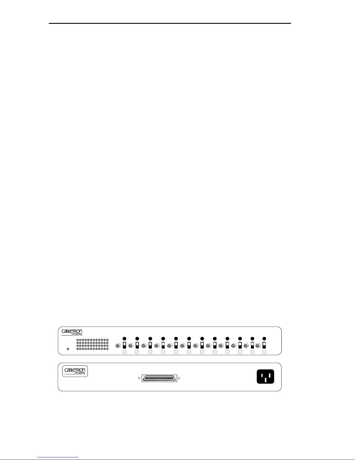
with a switch to provide internal termination. Figure 1-1 shows the
EMC37-12 ports.
Each of the rear panel twisted pair ports has a corresponding thin-net port
on the front panel.
For example
: Twisted pair Port 1 converts signals to thin-net port 1,
twisted pair port 2 converts signals to thin-net port 2, etc.
Front View
EMC37-12 ETHERNET MEDIA CONVERTER WITH LANVIEW
TPLINK
XMT
PWR
RCV
POK
12 11 10 9 8 7 6 5 4 3 2 1
EMC37-12
ETHERNET MEDIA CONVERTER
12 10987654321
11
1X 12X
Rear View
TERM
1-2 EMC37-12 USER’S GUIDE
Figure 1-1. The EMC37-12
Page 9

EMC37-12 FEATURES
1.4 EMC37-12 FEATURES
Automatic Transmit Port Disable
The EMC37-12 automatically disables the Transmit port when its
corresponding Receive port does not have a link.
LANVIEW Diagnostic LEDs
Cabletron equips the EMC37-12 with a visual diagnostic and monitoring
system called LANVIEW. LANVIEW LEDs help you quickly identify
Power and Link status.
Connectivity
The rear panel of the EMC37-12 has a 50-pin CHAMP connector (RJ-71)
that supports twelve twisted pair segments. The front panel has twelve
10BASE-T thin-net ports. Each thin-net port uses a BNC style receptacle
with a gold center contact.
1.5 EMC37-12 SPECIFICATIONS
This section describes operating specifications for the EMC37-12.
Cabletron Systems reserves the right to change these specifications at any
time without notice.
Physical Specifications
Dimensions: 17 L x 9.4 W x 1.7 H inches
(43.2 L x 23.9 W x 4.3 H cm)
Weight: 4 lbs (1.8 Kg)
Power Requirements
Input: 100 to 125 Vac, 1.0A
200 to 240 Vac, 0.5A
50 to 60 Hz
Environmental Requirements
Operating Temperature: +5° to +40°C (41° to 104°F)
Non-operating Temperature: -30
Operating Humidity: 5 to 95% (non-condensing)
EMC37-12 USER’S GUIDE 1-3
°
to +90°C (-22° to 194°F)
Page 10

CHAPTER 1:
INTRODUCTION
Safety and Approvals
This unit meets the safety requirements of UL 1950, CSA C22.2 NO 950,
and EN 60950; the EMI requirements of FCC Class A and EN 55022
Class A, VCCI Class I; and the EMC requirements of EN 50082-1.
1-4 EMC37-12 USER’S GUIDE
Page 11

CHAPTER 2
INSTALLATION
This chapter explains how to install the EMC37-12 in a 19-inch rack,
outlines requirements for installing the EMC37-12 on a tabletop or shelf
and provides procedures to connect the EMC37-12 to a power source.
2.1 UNPACKING THE EMC37-12
Unpack the EMC37-12 as follows:
1. Remove the shipping box material covering the EMC37-12.
2. Carefully remove the EMC37-12 from the shipping box.
3. Remove the EMC37-12 from its non-conductive bag. If you notice any
signs of damage, contact Cabletron Systems Technical Support
immediately.
2.2 INSTALLING THE EMC37-12
You can install the EMC37-12 in a 19-inch rack or place it on any
horizontal surface (e.g. a table or shelf). Cabletron provides an accessory
kit with the EMC37-12 that includes Rack Mount Brackets and Mounting
Screws.
The following sections provide instructions for installing the EMC37-12.
Select one of the following subsections and perform the steps that are
applicable to your installation needs.
EMC37-12 USER’S GUIDE 2-1
Page 12
CHAPTER 2:
INSTALLATION
2.2.1 Rack Mounting the EMC37-12
Before installing the EMC37-12, care must be taken to ensure that the
rack used will support the unit and that the rack remains stable with the
EMC37-12 installed. In order to allow for proper cooling within the rack,
there must be a two inch clearance on either side of the unit. Refer to
Chapter 1
The following procedures explain how to install the EMC37-12 in a
19-inch rack.
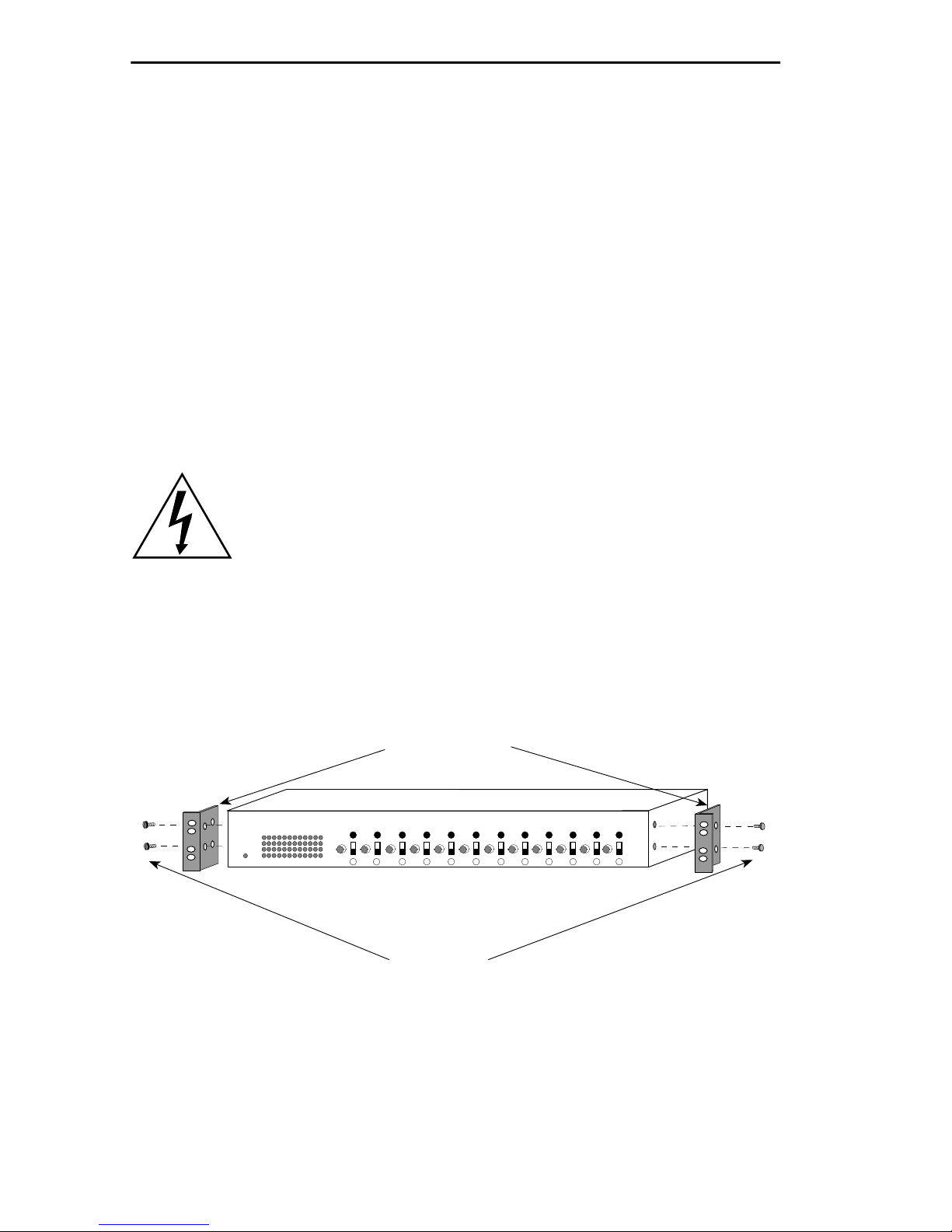
1. Remove four cover screws (two from each side) located along the
front edges of each side of the EMC37-12. Figure 2-1 shows the
location of the screws.
for power and environmental requirements.
Do not remove the cover from the EMC37-12.
2. Using the four replacement cover screws provided in the accessory kit,
attach the rack mounting brackets to each side of the EMC37-12.
Rack Mounting
Brackets (2)
EMC37-12
TPLINK
XMT
RCV
POK
PWR
12 11 10 9 8 7 6 5 4 3 2 1
ETHERNET MEDIA CONVERTER
12 1098765 4321
11
Figure 2-1. Installing the Rack Mount Brackets
WITH
LANVIEW
Screws (4)
TERM
2-2 EMC37-12 USER’S GUIDE
Page 13
INSTALLING THE EMC37-12
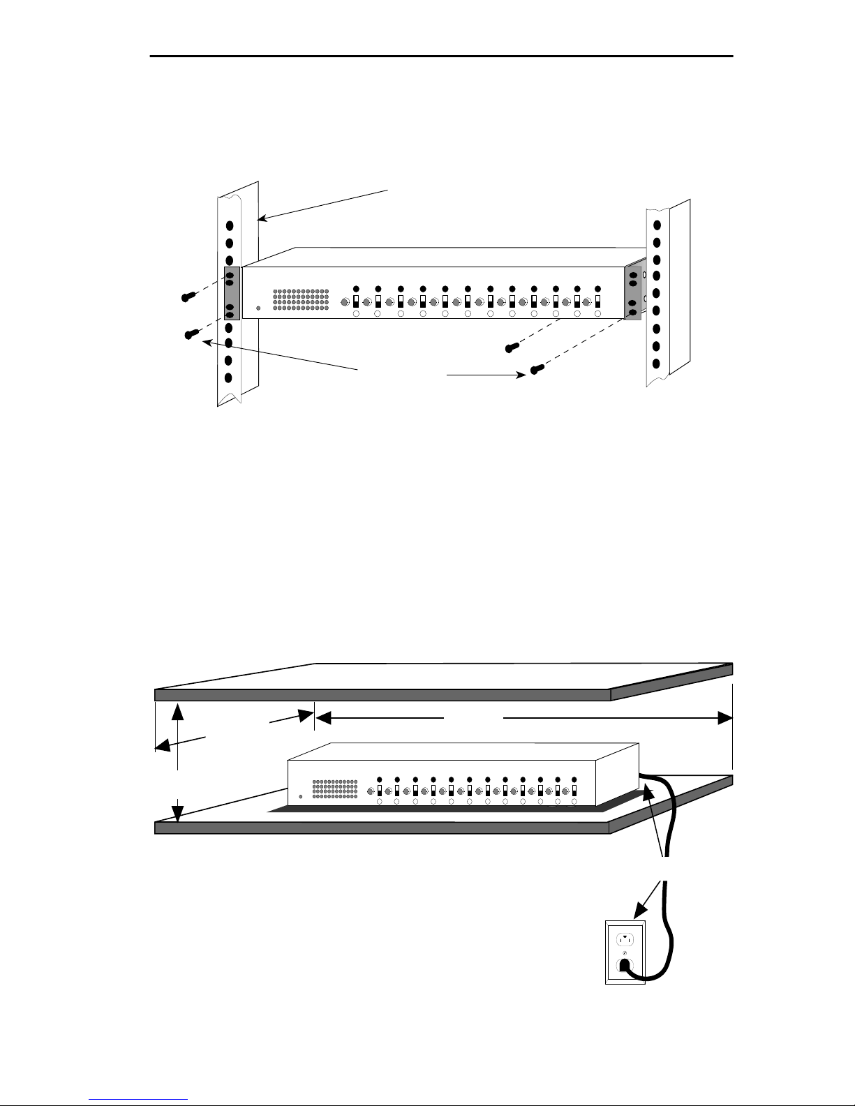
3. With the rack mounting brackets installed, position the EMC37-12
between the vertical frame members of the 19-inch rack and fasten it
securely with the mounting screws as shown in Figure 2-2.
19-Inch Rack
EMC37-12
ETHERNET MEDIA CONVERTER
TPLINK
XMT
RCV
POK
PWR
12 11 10 9 8 7 6 5 4 3 2 1
12 10987654321
11
Screws (4)
Figure 2-2. Installing the EMC37-12 in a 19-Inch Rack
WITH
LANVIEW
TERM
2.2.2 Free-Standing Shelf or Tabletop Installation
Figure 2-3 shows the surface requirements for installing the EMC37-12
on a shelf or tabletop. Shelving units must support 30 pounds of static
weight. Before installing the EMC37-12, ensure the power source and
environmental conditions meet the requirements specified in
21 IN.
18 IN.
EMC37-12
6 IN.
TPLINK
XMT
RCV
POK
PWR
12 11 10 9 8 7 6 5 4 3 2 1
ETHERNET MEDIA CONVERTER
12 10987654321
WITH
LANVIEW
11
TERM
Chapter 1
7 FT.
.
Figure 2-3. Shelf or Tabletop Installation
EMC37-12 USER’S GUIDE 2-3
Page 14

CHAPTER 2:
INSTALLATION
2.3 CONNECTING THE EMC37-12 TO THE POWER
SOURCE
Note
: The EMC37-12 has a universal power supply. This allows you to
connect the EMC37-12 to power sources from 100 Vac to 125 Vac,
50-60 Hz. or 200 Vac to 240 Vac, 50-60 Hz.
To connect the EMC37-12 to the power source:
1. Plug the power cord into the back panel of the EMC37-12.
2. Plug the other end of the power cord into a grounded wall outlet.
3. Verify that the
receiving power.
PWR
LED is on, this indicates that the EMC37-12 is
2-4 EMC37-12 USER’S GUIDE
Page 15
CHAPTER 3
CONNECTING TO THE NETWORK
This chapter outlines the procedure for connecting the EMC37-12 to your
network.
3.1 CONNECTING A TWISTED PAIR SEGMENT
TO THE EMC37-12
The rear panel of the EMC37-12 has a 50-pin CHAMP connector. This
section explains how to attach a twisted pair cable to the EMC37-12 and
to a 10BASE-T compliant Ethernet device that has a 50-pin CHAMP
connector (e.g., the Cabletron Systems TPRMIM or TPXMIM).
You can also run a 50-pin feeder cable from the EMC37-12 to a punch
down block. The CHAMP connector supports twelve 10BASE-T, twisted
pair segments.
Note
: Refer to
Appendix B
for information about wiring the EMC37-12 to
a punch down block.
To connect the EMC37-12 to a 10BASE-T compliant Ethernet device:
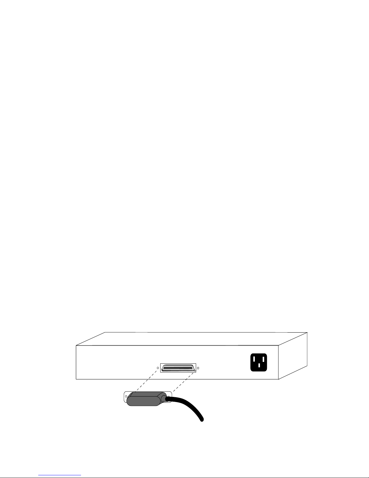
1. Attach a 50-pin feeder cable to the CHAMP connector on the
EMC37-12 as shown in Figure 3-1.
EMC37-12
Ethernet Media Converter
WITH
1X 12X
LANVIEW
EMC37-12 USER’S GUIDE 3-1
Figure 3-1. EMC37-12
Page 16

CHAPTER 3:
CONNECTING TO THE NETWORK
2. Attach the other end of the 50-pin feeder cable to the CHAMP
connector on the 10BASE-T compliant Ethernet device.
3. Check that the link LED on the 10BASE-T Ethernet device and the
applicable
TPLNK
LED on the EMC37-12 are ON. If the LEDs are
OFF, perform each of the following steps until the LEDs are ON:
Note
: The link LED on the 10BASE-T Ethernet device connected to the
EMC37-12 will not be ON unless the applicable coaxial 10BASE-2 port on
the front panel of the EMC37-12 is connected to a segment.
a. Check that the 10BASE-T device and the EMC37-12 have power.
b. Verify the cabling between the EMC37-12 and the 10BASE-T
device.
c. Verify the thin-net cabling between the EMC37-12 and the
10BASE-2 device for the applicable port and ensure that both
devices have power.
d. Check the cables for continuity.
If a link is not established, contact Cabletron Systems Technical Support.
3.2 CONNECTING A 10BASE-2 THIN-NET SEGMENT
The EMC37-12 has 12 10BASE-2 ports located on the front panel. This
section explains how to connect a thin-net segment to the EMC37-12.
To connect a thin-net segment to the EMC37-12, refer to Figure 3-2 and
perform the following steps:
1. Set the Internal Termination Switch located to the right of the port to:
• The ON position if the thin-net segment connected directly to the
port will be internally terminated at the port.
• The OFF position if the thin-net segment is not terminated at the port
or is externally terminated.
2. If the Internal Termination Switch is in the ON position, connect the
thin-net segment directly to the BNC port as shown in Figure 3-2.
3-2 EMC37-12 USER’S GUIDE
Page 17
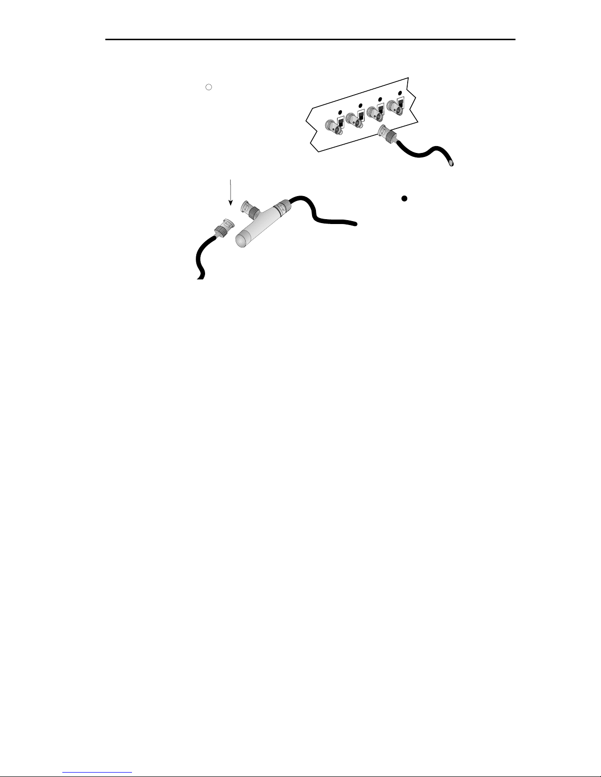
FINISHING THE INSTALLATION
When internal termination switch
is set to off ( ):
Connect BNC tee-connector to port.
Attach a terminator or terminated
thin-net segment to one female
connector of tee-connector.
Connect a terminated thin-net
segment to other female connector
of tee-connector.
Attach thin-net segment directly to BNC
connector when internal termination
switch is set to on ( ).
Figure 3-2. Connecting a thin-net segment to the EMC37-12
3. If the Internal Termination Switch is in the OFF position:
a. Attach a BNC tee-connector to the BNC port on the module.
b. Attach the thin-net segment to one of the female connectors on the
tee-connector.
Note
: You must terminate each segment attached to the tee-connector. If
you do not attach a segment to one of the female connections on the teeconnector, then a terminator must be placed on that connection.
c. Attach another thin-net segment or a terminator to the other
female connector of the tee-connector.
3.3 FINISHING THE INSTALLATION
The EMC37-12 is now ready for operation. Before placing the network
into service, test the installation thoroughly, making sure that you can
address all stations and that the EMC37-12 and all stations are indicating
normal operation. Ensure that the networking software is configured
properly to match the installed network. If you encounter errors or
abnormal operation, contact Cabletron Systems Technical Support.
EMC37-12 USER’S GUIDE 3-3
Page 18
CHAPTER 4
USING THE LANVIEW LEDS
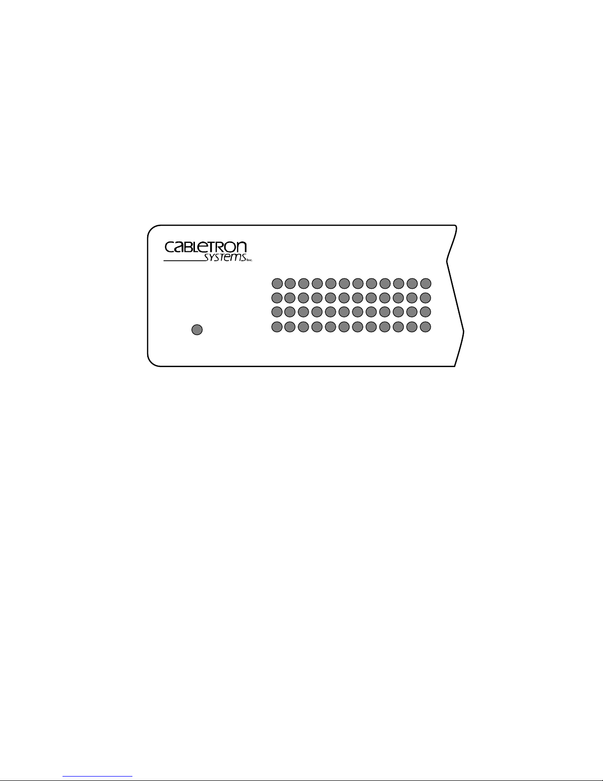
This chapter describes how to use the LANVIEW Diagnostic LEDs to
monitor EMC37-12 status and diagnose problems.
EMC37-12
TPLINK
XMT
RCV
PWR
POK
12 11 10 9 8 7 6 5 4 3 2 1
Figure 4-1. LANVIEW LEDS
EMC37-12 USER’S GUIDE 4-1
Page 19

CHAPTER 4: USING THE LANVIEW LEDS
Table 4-1. EMC37-12 LANVIEW LEDs
LED Color Description
PWR
(Power)
XMT
(Transmit)
RCV
(Receive)
OFF
Green
(solid)
OFF
Green
(flash)
OFF
Yellow
(flash)
Indicates that the unit is not receiving power. Check
the input power source (circuit breakers , fuse , power
cord, etc.). If the proper source is present, the problem could be with the unit.
Indicates that the EMC37-12 is receiving power.
No activity.
Indicates that the unit is transmitting data packets
from the twisted pair port to the thin-net port. The
flash is pulse stretched for viewing effect and may
appear to be on solid during periods of heavy traffic.
No activity.
Indicates that the unit is receiving data packets from
the associated thin-net port and transmitting them to
the twisted pair port. The flash is pulse stretched for
viewing effect and may appear to be on solid during
periods of heavy traffic.
TPLNK
(Link)
POK
(Port OK)
OFF
Green
(solid)
OFF
Green
(solid)
No link.
Indicates an established link between the associated
twisted pair segment and the 10BASE-T device at
the other end of the segment. This LED remains on
as long as there is a link between the devices and
power is supplied to both devices.
Indicates that the segment is not properly terminated
or that the device is malfunctioning.
Indicates a properly terminated coaxial segment.
4-2 EMC37-12 USER’S GUIDE
Page 20

APPENDIX A
CABLE REQUIREMENTS
This appendix provides cable requirements for each of the EMC37-12
ports.
A.1 10BASE-T TWISTED PAIR REQUIREMENTS
When you connect a 10BASE-T twisted pair segment to the EMC37-12,
the device at the other end of the twisted pair segment must meet IEEE
802.3 10BASE-T specifications. Your 10BASE-T twisted pair segment
must meet the following requirements.
Segment Length
The IEEE 802.3 10BASE-T standard requires that 10BASE-T devices
transmit to at least 100 meters (328 feet) per segment of 24-gauge
unshielded twisted pair (UTP) cable.
Insertion Loss
The maximum insertion loss allowed for a 10B ASE-T se gment is 11.5 dB
at all frequencies between 5.0 and 10.0 MHz. This includes the
attenuation of the cable, connectors, and patch panel.
Impedance
10BASE-T specifies cable impedance between 85 and 110 ohms.
EMC37-12 USER’S GUIDE A-1
Page 21

APPENDIX A: CABLE REQUIREMENTS
A.2 10BASE-2 THIN-NET NETWORK REQUIREMENTS
When you connect a 10BASE-2 thin-net se gment to the EMC37-12, your
network must meet the following requirements.
Cable Type
50 ohm RG-58A/U type coaxial cable must be used when making up a
thin-net segment.
Length
The thin-net segment must be no longer then 100 meters.
Terminators
A 50 ohm terminator must be connected to the far end of each thin-net
segment.
Devices
A maximum of 10 devices may be connected to a thin-net coax segment
on the EMC37-12, and these taps must be at least 0.5 meters apart. For
special network design, contact Cabletron Systems Technical Support.
System Characteristics
Since the EMC37-12 does not retime data, the operational limits of the
EMC37-12 may be determined by individual system jitter.
Grounding
The BNC ports of the EMC37-12 are internally connected to earth
ground.
Warning: For safety, one and only one end of any thin-net
segment should be connected to earth ground. Connecting a
thin-net segment to earth ground at more than one point could
produce dangerous ground currents. The BNC ports of the
EMC37-12 are internally connected to earth ground. No
other earth ground connection of these segments is required.
A-2 EMC37-12 USER’S GUIDE
Page 22

APPENDIX B
TWISTED PAIR WIRING TABLES
This appendix contains twisted pair wiring tables to assist you if you are
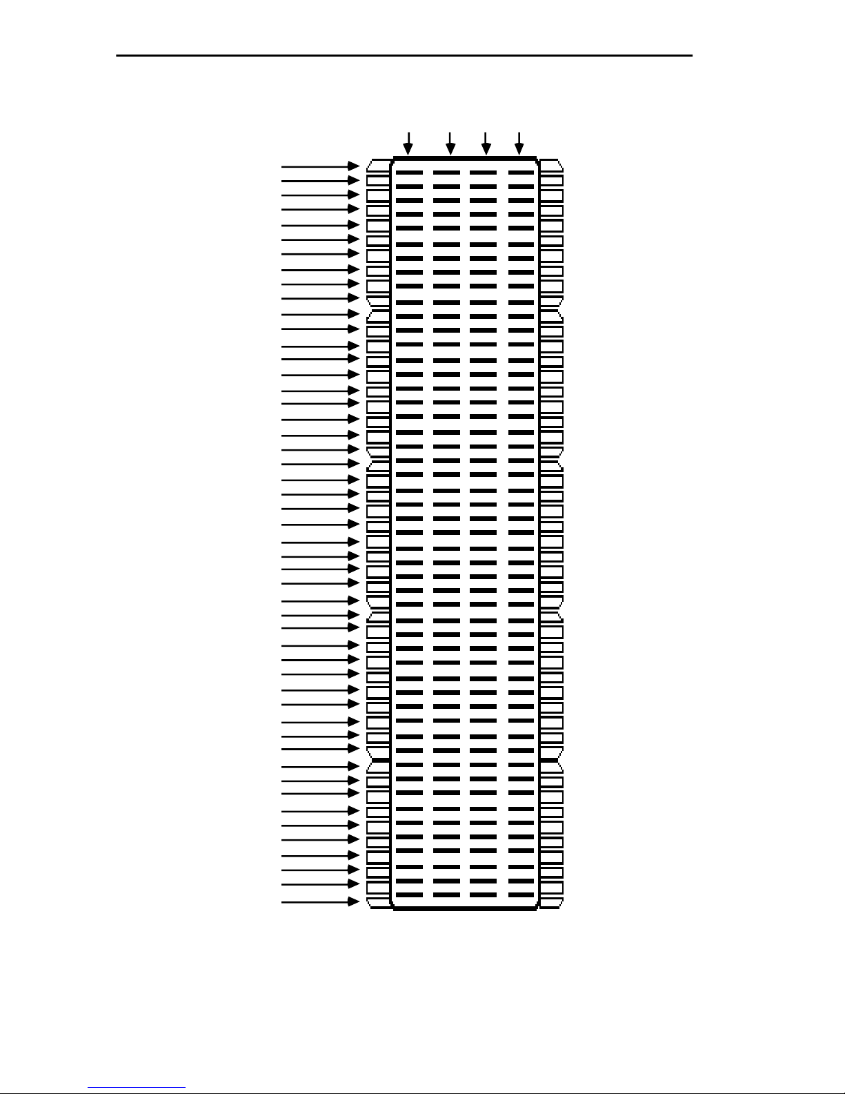
using a Punch Down Block (see Figure B-1) to wire your twisted pair
segments. The following tables are included in this appendix:
• T able B-1 Twisted Pair W iring from an EMC37-12 to a Punch Down
Block
• Table B-2 Twisted Pair Wiring from a Punch Down Block to a
10BASE-T Device
EMC37-12 USER’S GUIDE B-1
Page 23

APPENDIX B: TWISTED PAIR WIRING TABLES
B.1 TWISTED PAIR WIRING FROM AN EMC37-12 TO A
PUNCH DOWN BLOCK
Note: Pins 25 and 50 on the CHAMP connector are not used.
Table B-1. EMC37-12 to a Punch Down Block
From
EMC37-12
Port 12
Pin Pin Pin
TX+ 48 48 Violet/Green TX+ A45 Violet/Green TX+
TX- 23 23 Green/Violet TX- A46 Green/Violet TXRX+ 49 49 Violet/Brown RX+ A47 Violet/Brown RX+
RX- 24 24 Brown/Violet RX- A48 Brown/Violet RX-
Port 11
Pin Pin Pin
TX+ 46 46 Violet/Blue TX+ A41 Violet/Blue TX+
TX- 21 21 Blue/Violet TX- A42 Blue/Violet TXRX+ 47 47 Violet/Orange RX+ A43 Violet/Orange RX+
RX- 22 22 Orange/Violet RX- A44 Orange/Violet RX-
Into and Out of 50 Pin
Feeder Cable
Into Punch Down Block
Port 10
Pin Pin Pin
TX+ 44 44 Yellow/Brown TX+ A37 Yellow/Brown TX+
TX- 19 19 Brown/Yellow TX- A38 Brown/Yellow TXRX+ 45 45 Yellow/Gray RX+ A39 Yellow/Gray RX+
RX- 20 20 Gray/Yellow RX- A40 Gray/Yellow RX-
Port 9
Pin Pin Pin
TX+ 42 42 Yellow/Orange TX+ A33 Yellow/Orange TX+
TX- 17 17 Orange/Yellow TX- A34 Orange/Yellow TXRX+ 43 43 Yellow/Green RX+ A35 Yellow/Green RX+
RX- 18 18 Green/Yellow RX- A36 Green/Yellow RX-
B-2 EMC37-12 USER’S GUIDE
Page 24

TWISTED PAIR WIRING TABLES
Table B-1. EMC37-12 to a Punch Down Block (Continued)
From
EMC37-12
Port 8
Pin Pin Pin
TX+ 40 40 Black/Gray TX+ A29 Black/Gray TX+
TX- 15 15 Gray/Black TX- A30 Gray/Black TXRX+ 41 41 Yellow/Blue RX+ A31 Yellow/Blue RX+
RX- 16 16 Blue/Yellow RX- A32 Blue/Yellow RX-
Port 7
Pin Pin Pin
TX+ 38 38 Black/Green TX+ A25 Black/Green TX+
TX- 13 13 Green/Black TX- A26 Green/Black TXRX+ 39 39 Black/Brown RX+ A27 Black/Brown RX+
RX- 14 14 Brown/Black RX- A28 Brown/Black RX-
Into and Out of 50 Pin
Feeder Cable
Into Punch Down Block
Port 6
Pin Pin Pin
TX+ 36 36 Black/Blue TX+ A21 Black/Blue TX+
TX- 11 11 Blue/Black TX- A22 Blue/Black TXRX+ 37 37 Black/Orange RX+ A23 Black/Orange RX+
RX- 12 12 Orange/Black RX- A24 Orange/Black RX-
Port 5
Pin Pin Pin
TX+ 34 34 Red/Brown TX+ A17 Red/Brown TX+
TX- 9 9 Brown/Red TX- A18 Brown/Red TXRX+ 35 35 Red/Gray RX+ A19 Red/Gray RX+
RX- 10 10 Gray/Red RX- A20 Gray/Red RX-
EMC37-12 USER’S GUIDE B-3
Page 25

APPENDIX B: TWISTED PAIR WIRING TABLES
Table B-1. EMC37-12 to a Punch Down Block (Continued)
From
EMC37-12
Port 4
Pin Pin Pin
TX+ 32 32 Red/Orange TX+ A13 Red/Orange TX+
TX- 7 7 Orange/Red TX- A14 Orange/Red TXRX+ 33 33 Red/Green RX+ A15 Red/Green RX+
RX- 8 8 Green/Red RX- A16 Green/Red RX
Port 3
Pin Pin Pin
TX+ 30 30 White/Gray TX+ A9 White/Gray TX+
TX- 5 5 Gray/White TX- A10 Gray/White TXRX+ 31 31 Red/Blue RX+ A11 Red/Blue RX+
RX- 6 6 Blue/Red RX- A12 Blue/Red RX-
Into and Out of 50 Pin
Feeder Cable
Into Punch Down Block
Port 2
Pin Pin Pin
TX+ 28 28 White/Green TX+ A5 White/Green TX+
TX- 3 3 Green/White TX- A6 Green/White TXRX+ 29 29 White/Brown RX+ A7 White/Brown RX+
RX- 4 4 Brown/White RX- A8 Brown/White RX-
Port 1
Pin Pin Pin
TX+ 26 26 White/Blue TX+ A1 White/Blue TX+
TX- 1 1 Blue/White TX- A2 Blue/White TXRX+ 27 27 White/Orange RX+ A3 White/Orange RX+
RX- 2 2 Orange/White RX- A4 Orange/White RX-
B-4 EMC37-12 USER’S GUIDE
Page 26

TWISTED PAIR WIRING TABLES
B.2 TWISTED PAIR WIRING FROM A PUNCH DOWN
BLOCK TO A 10BASE-T DEVICE
Table B-2. Punch Down Block to a 10BASE-T Device
From Punch Down Block
Port 12 Pin Pin Pin
B45 Violet/Green RX+ 3 RX+ 3 RX+ 3 RX+
B46 Green/Violet RX- 6 RX- 6 RX- 6 RXB47 Violet/Brown TX+ 1 TX+ 1 TX+ 1 TX+
B48 Brown/Violet TX- 2 TX- 2 TX- 2 TX-
Port 11 Pin Pin Pin
B41 Violet/Blue RX+ 3 RX+ 3 RX+ 3 RX+
B42 Blue/Violet RX- 6 RX- 6 RX- 6 RXB43 Violet/Orange TX+ 1 TX+ 1 TX+ 1 TX+
To RJ45
Wallplate
Into
Office
Drop
Into
10BASE-T
Device
B44 Orange/Violet TX- 2 TX- 2 TX- 2 TX-
Port 10 Pin Pin Pin
B37 Yellow/Brown RX+ 3 RX+ 3 RX+ 3 RX+
B38 Brown/Yellow RX- 6 RX- 6 RX- 6 RXB39 Yellow/Gray TX+ 1 TX+ 1 TX+ 1 TX+
B40 Gray/Yellow TX- 2 TX- 2 TX- 2 TX-
Port 9 Pin Pin Pin
B33 Yellow/Orange RX+ 3 RX+ 3 RX+ 3 RX+
B34 Orange/Yellow RX- 6 RX- 6 RX- 6 RXB35 Yellow/Green TX+ 1 TX+ 1 TX+ 1 TX+
B36 Green/Yellow TX- 2 TX- 2 TX- 2 TX-
EMC37-12 USER’S GUIDE B-5
Page 27

APPENDIX B: TWISTED PAIR WIRING TABLES
Table B-2. Punch Down Block to a 10BASE-T Device (Continued)
From Punch Down Block
Port 8 Pin Pin Pin
B29 Black/Gray RX+ 3 RX+ 3 RX+ 3 RX+
B30 Gray/Black RX- 6 RX- 6 RX- 6 RXB31 Yellow/Blue TX+ 1 TX+ 1 TX+ 1 TX+
B32 Blue/Yellow TX- 2 TX- 2 TX- 2 TX-
Port 7 Pin Pin Pin
B25 Black/Green RX+ 3 RX+ 3 RX+ 3 RX+
B26 Green/Black RX- 6 RX- 6 RX- 6 RXB27 Black/Brown TX+ 1 TX+ 1 TX+ 1 TX+
To RJ45
Wallplate
Into
Office
Drop
Into
10BASE-T
Device
B28 Brown/Black TX- 2 TX- 2 TX- 2 TX-
Port 6 Pin Pin Pin
B21 Black/Blue RX+ 3 RX+ 3 RX+ 3 RX+
B22 Blue/Black RX- 6 RX- 6 RX- 6 RXB23 Black/Orange TX+ 1 TX+ 1 TX+ 1 TX+
B24 Orange/Black TX- 2 TX- 2 TX- 2 TX-
Port 5 Pin Pin Pin
B17 Red/Brown RX+ 3 RX+ 3 RX+ 3 RX+
B18 Brown/Red RX- 6 RX- 6 RX- 6 RXB19 Red/Gray TX+ 1 TX+ 1 TX+ 1 TX+
B20 Gray/Red TX- 2 TX- 2 TX- 2 TX-
B-6 EMC37-12 USER’S GUIDE
Page 28

TWISTED PAIR WIRING TABLES
Table B-2. Punch Down Block to a 10BASE-T Device (Continued)
From Punch Down Block
Port 4 Pin Pin Pin
B13 Red/Orange RX+ 3 RX+ 3 RX+ 3 RX+
B14 Orange/Red RX- 6 RX- 6 RX- 6 RXB15 Red/Green TX+ 1 TX+ 1 TX+ 1 TXB16 Green/Red TX- 2 TX- 2 TX- 2 TX-
Port 3 Pin Pin Pin
B9 White/Gray RX+ 3 RX+ 3 RX+ 3 RX+
B10 Gray/White RX- 6 RX- 6 RX- 6 RXB11 Red/Blue TX+ 11 TX+ 1 TX+ 1 TX+
To RJ45
Wallplate
Into
Office
Drop
Into
10BASE-T
Device
B12 Blue/Red TX- 2 TX- 2 TX- 2 TX-
Port 2 Pin Pin Pin
B5 White/Green RX+ 3 RX+ 3 RX+ 3 RX+
B6 Green/White RX- 6 RX- 6 RX- 6 RXB7 White/Brown TX+ 1 TX+ 1 TX+ 1 TX+
B8 Brown/White TX- 2 TX- 2 TX- 2 TX-
Port 1 Pin Pin Pin
B1 White/Blue RX+ 3 RX+ 3 RX+ 3 RX+
B2 Blue/White RX- 6 RX- 6 RX- 6 RXB3 White/Orange TX+ 1 TX+ 1 TX+ 1 TX+
B4 Orange/White TX- 2 TX- 2 TX- 2 TX-
EMC37-12 USER’S GUIDE B-7
Page 29
APPENDIX B: TWISTED PAIR WIRING TABLES
A B C D
1
2
3
4
5
6
7
8
9
10
11
12
13
14
15
16
17
18
19
20
21
22
23
24
25
26
27
28
29
30
31
32
33
34
35
36
37
38
39
40
41
42
43
44
45
46
47
48
49
50
Figure B-1. Punch Down Block Pinout
B-8 EMC37-12 USER’S GUIDE
Page 30

POWER SUPPLY CORD
The mains cord used with this equipment must be a 2 conductor plus
ground type with minimum 0.75 mm square conductors and must
incorporate a standard IEC appliance coupler on one end and a mains plug
on the other end which is suitable for the use and application of the product
and that is approved for use in the country of application.
GERMAN:
Die Netzleitung, die mit diesem Geraet benuetzt wird, soll einen zwei
Leiter mit Erdleiter haben, wobei die Leiter mindestens 0.75 mm sind, mit
einer normalen IEC Geraetesteckdose an einem Ende und einem
Geraetestecker am anderen Ende versehen sind, der fuer den Gebrauch und
die Anwendung des Geraetes geeignet und der zum Benuetzen im Lande
der Anwendung anerkannt ist.
SPANISH:
El cable principal de la red eléctrica utilizado con este equipo debe tener 2
conductores y 1 toma de tierra con un mínimo de 0.75 mm2 cada uno y
necesita tener un aparato de acoplamiento standard IEC en un extremo y
un enchufe para el cable principal de la red eléctrica en el otro extremo, lo
cual sea adecuado para el uso y
applicación del producto y lo cual sea aprobado para uso en el pais de
applicación.
FRENCH:
Le cordon d' alimentation reliant cet appareil au secteur doit
obligatoirement avoir deux fils conducteurs de 0.75 mm2 minimum et un
fil de terre. It doit également être équipé du côté appareil d'une fiche agrée
IEC et du côte secteur, d'une prise adaptée à l'usage du produit et aux
normes du pays où l'appareil est utilisé.
 Loading...