

Page 1

SmartSTACK 100
ELS100-24TXM
ETHERNET SWITCH
INSTALLATION
AND
USER GUIDE
Page 2

Only qualified personnel should perform installation
procedures.
NOTICE
Cabletron Systems reserves the right to make changes in specifications and other information contained in this document without prior notice. The reader should in all cases consult
Cabletron Systems to determine whether any such changes have been made.
The hardware, firmware, or software described in this manual is subject to change without
notice.
IN NO EVENT SHALL CABLETRON SYSTEMS BE LIABLE FOR ANY INCIDENTAL, INDIRECT, SPECIAL, OR CONSEQUENTIAL DAMAGES WHATSOEVER (INCLUDING BUT
NOT LIMITED TO LOST PROFITS) ARISING OUT OF OR RELATED TO THIS MANUAL OR
THE INFORMATION CONTAINED IN IT, EVEN IF CABLETRON SYS TEMS HAS BEEN ADVISED OF, KNOWN, OR SHOULD HAVE KNOWN, THE POSSIBILITY OF SUCH DAMAGES.
© Copyright 1998 by Cabletron Systems, Inc., P.O. Box 5005, Rochester, NH 03866-5005
All Rights Reserved
Printed in the United States of America
Part Number: 9032785 September 1998
ELS100-24TX is a trademark of Cabletron Systems, Inc.
All other product names mentioned in this manual may be trademarks or registered trademarks of their respective companies.
FCC NOTICE
This device complies wit h Part 15 of the F CC ru les. Oper atio n is subje ct to the fo llo wing two
conditions: (1) this device may not cause harmful interference, and (2) this device must accept any interference received, including interference that may cause undesired operation.
NOTE: This equipme nt has been tested and fo und to compl y with the l imits for a Class A digital device, pursuant to Part 15 of the FCC rules. These limits are designed to provide reasonable protection against harmful interference when the equipment is operated in a
commercial environment. Th is equipment uses, generates, and can radiate radio frequency
energy and if not installed in accordance with the operator’s manual, may cause harmful interference to radio communications. Operation of this equipment in a residential area is likely
to cause interfer ence in wh ich case th e user w ill be re quired to correct t he interf erence at his
own expense.
WARNING: Changes or mo difications made to th is device which ar e not ex pressly appro ved
by the party responsible for compliance could void the user’s authority to operate the equip-
ment.
Printed on Recycled Paper
Page 3

DOC NOTICE
This digital apparatus do es no t exce ed the C lass A l imit s for radi o no is e emi ssion s f rom d igital apparatus set out in the Radio Interference Regulations of the Canadian Department of
Communications.
Le présent appareil numérique n’émet pas de bruits radioélectriques dépassant les limites
applicables aux appareils numériques de la class A prescrites dans le Règlement sur le
brouillage radioélectrique édicté par le ministère des Communications du Canada.
VCCI NOTICE
This is a Class A prod uct base d on t he stan dard of the Vo luntar y Con trol Cou ncil fo r Inte rfer ence by Information Technology Equipment (VCCI). If this equipment is used in a domestic
environment, radio disturbance may arise. When such trouble occurs, the user may be required to take corrective actions.
CABLETRON SYSTEMS, INC.
PROGRAM LICENSE AGREEMENT
IMPORTANT: Before utilizing this product, carefully read this License Agreement.
This document is an agreement between you, the end user, and Cabletron Systems, Inc.
(“Cabletron”) that sets for th your rights and obl igations with respect to the C abletron software
program (the “Program”) contai ned in this package. The Program may be contained in firmware, chips or other media. BY UTILIZING THE ENCLOSED PRODUCT, YOU ARE AGREEING TO BECOME BOUND BY THE TERMS OF THIS AGREEMENT, WHICH INCLUDES
THE LICENSE AND THE LIMITATION OF W ARR ANTY AN D D ISCL AIM ER OF LI ABI LITY.
IF YOU DO NOT AGREE TO THE TERMS OF THIS AGREEMENT, PROMPTLY RETURN
THE UNUSED PRODUCT TO THE PLACE OF PURCHASE FOR A FULL REFUND.
CABLETRON SOFTWARE PROGRAM LICENSE
1. LICENSE. You have the right to use only the one (1) copy of the Program provide d
in this package subject to the terms and conditions of this Licens e Agreement.
You may not copy, reproduce or transmit any part of the Program except as permitted by the Copyright Act of the United States or as authorized in writing by
Cabletron.
2. OTHER RESTRICTIONS
ble the Progra m.
3. APPLICABLE LAW
under the laws an d i n th e state a nd fe der a l cou rt s of New Hampshire. You accept
the personal jurisdiction and venue of the New Hampshire courts.
. You may not reverse engineer, decompile, or disassem-
. This License Agreement shall be interpreted and governed
Page 4

EXCLUSION OF WARRANTY
AND DISCLAIMER OF LIABILITY
1. EXCLUSION OF WARRANTY. Except as may be spe ci fi call y p ro vided b y Cab l etron i n
writing, Cabletron makes no warranty, expressed or implied, c oncerning the Program (including its documentation and media).
CABLETRON DISCLAIMS ALL WARRANTIES, OTHER THAN THOSE SUPPLIED TO YOU BY CABLETRON IN WRITING, EITHER EXPRESSED OR IMPLIED, INCLUDING BUT NOT LIMITED TO IMPLIED WARRANTIES OF
MERCHANTABILITY AND FITNESS FOR A PARTICULAR PURPOSE, WITH RESPECT TO THE PROGRAM, THE ACCOMPANYING WRITTEN MATERIALS,
AND ANY ACCOMPANYING HA RDW AR E.
2. NO LIABILITY FOR CONSEQUENTIAL DAMAGES
CABLETRON OR ITS SUPPLIERS BE LIABLE FOR ANY DAMAGES WHATSOEVER (INCLUDING, WITHOUT LIMITATION, DAMAGES FOR LOSS OF BUSINESS, PROFITS, BUSINESS INTERRUPTION, LOSS OF BUSINESS
INFORMATION, SPECIAL, INCIDENTAL, CONSEQUENTIAL, OR RELIANCE
DAMAGES, OR OTHER LOSS) ARISING OUT OF THE USE OR INABILITY TO
USE THIS CABLETRON PRODUCT, EVEN IF CABLETRON HAS BEEN ADVISED OF THE POSSIBI LITY OF SUCH DA MAGES. BE CAUSE SOME STATES
DO NOT ALLOW THE EXCLUSION OR LIMITATION OF LIABILITY FOR CONSEQUENTIAL OR INCIDENTAL DAMAGES, OR ON THE DURATION OR LIMITATION OF IMPLIED WARRANTIES, IN SOME INSTANCES THE ABOVE
LIMITATIONS AND EXCLUSIONS MAY NOT APPLY TO YOU.
. IN NO EVENT SHALL
UNITED STATES GOVERNMENT RESTRICTED RIGHTS
The enclosed product (a) was developed solely at private expense; (b) contains “restricted
computer software” submitted with restricted right s in accordance with Section 522 27-19 (a)
through (d) of th e Commerci al Comput er Softwar e - Restri cted Rights C lause and its successors, and (c) in all respects is proprietary data belonging to Cabletron and/or its suppliers.
For Department of Defense un its, th e prod uct is lice nsed wi th “Restr icted Rights” as defi ned
in the DoD Supplement to the Federal Acquisition Regulations, Section 52.227-7013 (c) (1)
(ii) and its successors, and use, duplication, disclosure by the Government is subject to restrictions as set fo rth in subparagr aph (c) (1) (ii) of the Rights in Technical Data and Computer
Software clause at 252.227-7013. Cabletron Systems, Inc., 35 Industrial Way, Rochester,
New Hampshire 03867-0505.
SAFETY INFORMATION
LASER RADIATION AND CONNECTORS
When the connector is in place, all laser radiation remains within the fiber. The maximum
amount of radiant power exiting the fiber (under normal conditions) is - 12.6 dBm or 55 x 10
6
watts. Removing the optical connector from the transceiver allows laser radiation to emit
directly from the opti cal por t. T he ma ximum radia nce fr om th e opt ical port (under wo rst case
-2
conditions) is 0.8 W cm
Do not use opt ical instruments to view the lase r output. The use of optical instruments to view
laser output increases eye hazard. When viewing the output optical port, power must be removed from the network adapter.
or 8 x 10 3 W m 2 sr-1.
-
Page 5

DECLARATION OF CONFORMITY
Application of Council Directive(s): 89/336/EEC
73/23/EEC
Manufacturer’s Name: Cabletron Systems, Inc.
Manufacturer’s Address: 35 Industrial Way
PO Box 5005
Rochester, NH 03867
European Representative Name: Mr. J. Solari
European Represent ati ve Add r ess: Cabletron Systems Limited
Nexus House, Newbury Business Park
London Road, Newbury
Berkshire RG13 2PZ, England
Conformance to Directive(s)/
Product Standards: EC Directive 89/336/EEC
EC Directive 73/23/EEC
EN 55022
EN 50082-1
EN 60950
Equipment Type/Environment: Networking Equipment, for use in a Com-
mercial or Light Industrial Environment.
We the undersigned, hereby declare, under our sole responsibility, that the equipment packaged with this notice conforms to the above directives.
Manufacturer Legal Representative in Europe
Mr. Ronald Fotino
Full Name Full Name
Principal Compliance Engineer
Title Title
Rochester, NH, USA
Location Location
Newbury, Berkshire, England
Managing Director - E.M.E.A.
Mr. J. Solari
Page 6

Page 7

TABLE OF CONTENTS
PREFACE. . . . . . . . . . . . . . . . . . . . . . . . . . . . . . . . . . . . . . . . . . . . . . . . Preface i
Purpose. . . . . . . . . . . . . . . . . . . . . . . . . . . . . . . . . . . . . . . . . . . . . . . . . . i
Audience. . . . . . . . . . . . . . . . . . . . . . . . . . . . . . . . . . . . . . . . . . . . . . . . . i
Conventions . . . . . . . . . . . . . . . . . . . . . . . . . . . . . . . . . . . . . . . . . . . . . . i
Message Formats . . . . . . . . . . . . . . . . . . . . . . . . . . . . . . . . . . . . . . i
Keyboard Entries . . . . . . . . . . . . . . . . . . . . . . . . . . . . . . . . . . . . . . . ii
Other Conventions. . . . . . . . . . . . . . . . . . . . . . . . . . . . . . . . . . . . . . ii
Organization . . . . . . . . . . . . . . . . . . . . . . . . . . . . . . . . . . . . . . . . . . . . . . ii
1. PRODUCT OVERVIEW. . . . . . . . . . . . . . . . . . . . . . . . . . . . . . . . . . . . . . . . . .1
Description . . . . . . . . . . . . . . . . . . . . . . . . . . . . . . . . . . . . . . . . . . . . . . .1
Features . . . . . . . . . . . . . . . . . . . . . . . . . . . . . . . . . . . . . . . . . . . . . . . . .2
Front Panel . . . . . . . . . . . . . . . . . . . . . . . . . . . . . . . . . . . . . . . . . . . . . . .3
Rear Panel . . . . . . . . . . . . . . . . . . . . . . . . . . . . . . . . . . . . . . . . . . . . . . . 6
Feature Summaries . . . . . . . . . . . . . . . . . . . . . . . . . . . . . . . . . . . . . . . .6
IEEE 802.1D Bridge. . . . . . . . . . . . . . . . . . . . . . . . . . . . . . . . . . . . .6
Spanning Tree Protocol. . . . . . . . . . . . . . . . . . . . . . . . . . . . . . . . . .7
Frame Buffering and Fram e Lat ency . . . . . . . . . . . . . . . . . . . . . . . . 7
Software Download . . . . . . . . . . . . . . . . . . . . . . . . . . . . . . . . . . . . .7
Non-volatile Parameter Storage . . . . . . . . . . . . . . . . . . . . . . . . . . .7
Configuration and Man agement Interfaces . . . . . . . . . . . . . . . . . . . 8
RMON . . . . . . . . . . . . . . . . . . . . . . . . . . . . . . . . . . . . . . . . . . . . . . .8
Port Mirroring. . . . . . . . . . . . . . . . . . . . . . . . . . . . . . . . . . . . . . . . . .9
Auto-negotiation. . . . . . . . . . . . . . . . . . . . . . . . . . . . . . . . . . . . . . . . 9
Broadcast Thrott ling . . . . . . . . . . . . . . . . . . . . . . . . . . . . . . . . . . . . . 9
BootP/DHCP . . . . . . . . . . . . . . . . . . . . . . . . . . . . . . . . . . . . . . . . .10
LEDs . . . . . . . . . . . . . . . . . . . . . . . . . . . . . . . . . . . . . . . . . . . . . . .10
Full Duplex Mode. . . . . . . . . . . . . . . . . . . . . . . . . . . . . . . . . . . . . .10
Flow Control. . . . . . . . . . . . . . . . . . . . . . . . . . . . . . . . . . . . . . . . . .10
Virtual LANs (VLANs) . . . . . . . . . . . . . . . . . . . . . . . . . . . . . . . . . .10
Class of Service. . . . . . . . . . . . . . . . . . . . . . . . . . . . . . . . . . . . . . .11
Application Examples . . . . . . . . . . . . . . . . . . . . . . . . . . . . . . . . . . . . . .11
Client/Server Network Application. . . . . . . . . . . . . . . . . . . . . . . . .12
Local Backbone Application. . . . . . . . . . . . . . . . . . . . . . . . . . . . . .13
2. INSTALLATION. . . . . . . . . . . . . . . . . . . . . . . . . . . . . . . . . . . . . . . . . . . . . . .15
Inspecting Your Shipment. . . . . . . . . . . . . . . . . . . . . . . . . . . . . . . . . . .15
Site Requirements . . . . . . . . . . . . . . . . . . . . . . . . . . . . . . . . . . . . . . . .15
Mounting the Switch on a Table or Shelf . . . . . . . . . . . . . . . . . . . . . . .16
Mounting the Switch on a Wall . . . . . . . . . . . . . . . . . . . . . . . . . . . . . . .17
Mounting the Switch in a Rack . . . . . . . . . . . . . . . . . . . . . . . . . . . . . . .18
Installing a Fiber Uplink Module into the Switch . . . . . . . . . . . . . . . . . .19
Connecting a Terminal to t he Console Port . . . . . . . . . . . . . . . . . . . . . 20
Powering the Switch . . . . . . . . . . . . . . . . . . . . . . . . . . . . . . . . . . . . . .21
Power-Up. . . . . . . . . . . . . . . . . . . . . . . . . . . . . . . . . . . . . . . . . . . .21
ELS100-24TXM Table of Contents i
Page 8

Network Cable Requirements . . . . . . . . . . . . . . . . . . . . . . . . . . . . . . . 22
Copper . . . . . . . . . . . . . . . . . . . . . . . . . . . . . . . . . . . . . . . . . . . . . 22
Fiber . . . . . . . . . . . . . . . . . . . . . . . . . . . . . . . . . . . . . . . . . . . . . . . 22
10Base-T/100Base-TX Po r ts . . . . . . . . . . . . . . . . . . . . . . . . . . . . . . . . 23
100Base-FX Fiber Port s. . . . . . . . . . . . . . . . . . . . . . . . . . . . . . . . . . . . 24
Fiber Uplink Modules . . . . . . . . . . . . . . . . . . . . . . . . . . . . . . . . . . 24
3. ELS100-24TXM USER INTERFACE . . . . . . . . . . . . . . . . . . . . . . . . . . . . . . 25
Overview . . . . . . . . . . . . . . . . . . . . . . . . . . . . . . . . . . . . . . . . . . . . . . . 25
User Access. . . . . . . . . . . . . . . . . . . . . . . . . . . . . . . . . . . . . . . . . . . . . 26
Factory Defaults. . . . . . . . . . . . . . . . . . . . . . . . . . . . . . . . . . . . . . . . . . 27
Menu Hierarchy . . . . . . . . . . . . . . . . . . . . . . . . . . . . . . . . . . . . . . . . . . 28
Main Menu . . . . . . . . . . . . . . . . . . . . . . . . . . . . . . . . . . . . . . . . . . . . . . 29
System Configuration Menu. . . . . . . . . . . . . . . . . . . . . . . . . . . . . . . . . 30
SNMP Configuration Menu. . . . . . . . . . . . . . . . . . . . . . . . . . . . . . . . . . 31
Switch Configuration Menu . . . . . . . . . . . . . . . . . . . . . . . . . . . . . . . . . 32
Forwarding Table Configuration Menu. . . . . . . . . . . . . . . . . . . . . . . . . 33
Spanning Tree Configuration Menu. . . . . . . . . . . . . . . . . . . . . . . . . . . 35
Spanning Tree Port Configuration Menu . . . . . . . . . . . . . . . . . . . . . . . 37
Spanning Tree Port #n Configuration Menu. . . . . . . . . . . . . . . . . . . . . 38
VLAN Configuration Menu . . . . . . . . . . . . . . . . . . . . . . . . . . . . . . . . . . 39
VLAN Menu . . . . . . . . . . . . . . . . . . . . . . . . . . . . . . . . . . . . . . . . . . . . . 40
VLAN #n Configuration Menu. . . . . . . . . . . . . . . . . . . . . . . . . . . . . . . . 41
VLAN Port Menu . . . . . . . . . . . . . . . . . . . . . . . . . . . . . . . . . . . . . . . . . 42
Class of Service Configuration Menu. . . . . . . . . . . . . . . . . . . . . . . . . . 43
Port Priority Menu. . . . . . . . . . . . . . . . . . . . . . . . . . . . . . . . . . . . . . . . . 44
Port Menu. . . . . . . . . . . . . . . . . . . . . . . . . . . . . . . . . . . . . . . . . . . . . . . 45
Port Configuration Menu . . . . . . . . . . . . . . . . . . . . . . . . . . . . . . . . . . . 46
Switch Statistics Screen. . . . . . . . . . . . . . . . . . . . . . . . . . . . . . . . . . . . 47
Switch Summary Screen . . . . . . . . . . . . . . . . . . . . . . . . . . . . . . . . . . . 48
Port Statistics Screen. . . . . . . . . . . . . . . . . . . . . . . . . . . . . . . . . . . . . . 49
General Information Screen. . . . . . . . . . . . . . . . . . . . . . . . . . . . . . . . . 51
Download Software M enu . . . . . . . . . . . . . . . . . . . . . . . . . . . . . . . . . . 52
Save Current Configuration . . . . . . . . . . . . . . . . . . . . . . . . . . . . . . . . . 53
Return to Default Configuration . . . . . . . . . . . . . . . . . . . . . . . . . . . . . . 53
Logout . . . . . . . . . . . . . . . . . . . . . . . . . . . . . . . . . . . . . . . . . . . . . . . . . 53
Reset . . . . . . . . . . . . . . . . . . . . . . . . . . . . . . . . . . . . . . . . . . . . . . . . . . 54
4. CONFIGURING & MONITORING THE SWITCH . . . . . . . . . . . . . . . . . . . . . 55
Common Tasks . . . . . . . . . . . . . . . . . . . . . . . . . . . . . . . . . . . . . . . . . . 55
Setting Password Protection . . . . . . . . . . . . . . . . . . . . . . . . . . . . . . . . 56
Assigning an IP Address . . . . . . . . . . . . . . . . . . . . . . . . . . . . . . . . . . . 57
Checking Network Configuration Status. . . . . . . . . . . . . . . . . . . . . . . . 57
Connecting via Telnet . . . . . . . . . . . . . . . . . . . . . . . . . . . . . . . . . . . . . 57
Setting SNMP Management Access . . . . . . . . . . . . . . . . . . . . . . . . . . 58
Viewing Switch Statistics . . . . . . . . . . . . . . . . . . . . . . . . . . . . . . . . . . . 58
Configuring Port Mirroring . . . . . . . . . . . . . . . . . . . . . . . . . . . . . . . . . . 59
ii Table of Contents ELS100-24TXM
Page 9

Downloading a Software Upgrade . . . . . . . . . . . . . . . . . . . . . . . . . . . .59
Downloading Via the Ser ial Port . . . . . . . . . . . . . . . . . . . . . . . . . . 60
Downloading Via TFTP . . . . . . . . . . . . . . . . . . . . . . . . . . . . . . . . . 60
Configuring Spanning Tree Parameters . . . . . . . . . . . . . . . . . . . . . . . .61
Configuring VLANs . . . . . . . . . . . . . . . . . . . . . . . . . . . . . . . . . . . . . . . .62
Configuring Class of Service. . . . . . . . . . . . . . . . . . . . . . . . . . . . . . . . .62
Configuring Port Operation. . . . . . . . . . . . . . . . . . . . . . . . . . . . . . . . . .63
Configuring the Forwarding Table. . . . . . . . . . . . . . . . . . . . . . . . . . . . .64
Configuring Broadcast Cutoff Rate. . . . . . . . . . . . . . . . . . . . . . . . . . . .65
Setting a Default Gateway . . . . . . . . . . . . . . . . . . . . . . . . . . . . . . . . . .66
Configuring BootP/DHCP . . . . . . . . . . . . . . . . . . . . . . . . . . . . . . . . . . .66
5. SNMP MANAGEMENT . . . . . . . . . . . . . . . . . . . . . . . . . . . . . . . . . . . . . . . . .67
The SNMP Protocol . . . . . . . . . . . . . . . . . . . . . . . . . . . . . . . . . . . . . . .67
MIB Objects . . . . . . . . . . . . . . . . . . . . . . . . . . . . . . . . . . . . . . . . . . . . .68
RFC 1213 (MIB-II) . . . . . . . . . . . . . . . . . . . . . . . . . . . . . . . . . . . . . 68
RFC 1398 (Ethernet MIB) . . . . . . . . . . . . . . . . . . . . . . . . . . . . . . . 69
RFC 1493 (Bridge MIB) . . . . . . . . . . . . . . . . . . . . . . . . . . . . . . . . . 69
RFC 1757 (RMON MIB). . . . . . . . . . . . . . . . . . . . . . . . . . . . . . . . . 6 9
Cabletron Systems Proprietary MIB Extensions . . . . . . . . . . . . . .70
Compiling MIB Extensions: Cabletron Website. . . . . . . . . . . . . . . . . . .73
APPENDIX A. TECHNICAL SPECIFICATIONS . . . . . . . . . . . . . . . . . . . . . . . .75
General . . . . . . . . . . . . . . . . . . . . . . . . . . . . . . . . . . . . . . . . . . . . . . . . . 7 5
Standards Compliance . . . . . . . . . . . . . . . . . . . . . . . . . . . . . . . . . 75
Certification . . . . . . . . . . . . . . . . . . . . . . . . . . . . . . . . . . . . . . . . . .75
Data Rate. . . . . . . . . . . . . . . . . . . . . . . . . . . . . . . . . . . . . . . . . . . .75
Environmental Specifications. . . . . . . . . . . . . . . . . . . . . . . . . . . . .75
Electrical Specifications. . . . . . . . . . . . . . . . . . . . . . . . . . . . . . . . .76
Physical . . . . . . . . . . . . . . . . . . . . . . . . . . . . . . . . . . . . . . . . . . . . .76
Microprocessor . . . . . . . . . . . . . . . . . . . . . . . . . . . . . . . . . . . . . . .76
Memory . . . . . . . . . . . . . . . . . . . . . . . . . . . . . . . . . . . . . . . . . . . . .76
Port Specifications . . . . . . . . . . . . . . . . . . . . . . . . . . . . . . . . . . . . . . . .77
Console Port . . . . . . . . . . . . . . . . . . . . . . . . . . . . . . . . . . . . . . . . .77
10Base-T and 100Base-TX Ports . . . . . . . . . . . . . . . . . . . . . . . . . 77
MDI/MDI-X Crossover Cable Wiring . . . . . . . . . . . . . . . . . . . . . . .78
Power Cord Set Requirements . . . . . . . . . . . . . . . . . . . . . . . . . . . . . . .78
General Requirements. . . . . . . . . . . . . . . . . . . . . . . . . . . . . . . . . .78
Country-Specific Requirements . . . . . . . . . . . . . . . . . . . . . . . . . . . 79
APPENDIX B. SPANNING TREE CONCEPTS. . . . . . . . . . . . . . . . . . . . . . . . .81
General . . . . . . . . . . . . . . . . . . . . . . . . . . . . . . . . . . . . . . . . . . . . . . . . . 8 1
Spanning Tree Features . . . . . . . . . . . . . . . . . . . . . . . . . . . . . . . . . . . . 81
Spanning Tree Protocol in a Net work . . . . . . . . . . . . . . . . . . . . . . . . . . 82
Spanning Tree Protocol Par a m e t e r s. . . . . . . . . . . . . . . . . . . . . . . . . . . 83
Spanning Tree Protocol Operation . . . . . . . . . . . . . . . . . . . . . . . . . . . . 84
Communicating Between Bridges . . . . . . . . . . . . . . . . . . . . . . . . .84
Selecting a Root Bridge and Designated Bridges . . . . . . . . . . . . . 84
Selecting Designated Ports . . . . . . . . . . . . . . . . . . . . . . . . . . . . . .84
ELS100-24TXM Table of Contents iii
Page 10

Handling Duplicate Pa ths . . . . . . . . . . . . . . . . . . . . . . . . . . . . . . . 84
Remapping Networ k Topology . . . . . . . . . . . . . . . . . . . . . . . . . . . 84
APPENDIX C. FLOW CONTROL. . . . . . . . . . . . . . . . . . . . . . . . . . . . . . . . . . . 87
APPENDIX D. VIRTUAL LANS (VLANS). . . . . . . . . . . . . . . . . . . . . . . . . . . . . 89
VLANs and Frame Tagging . . . . . . . . . . . . . . . . . . . . . . . . . . . . . . . . . 89
ELS100-24TXM VLAN Co nfiguration. . . . . . . . . . . . . . . . . . . . . . . . . . 90
VLAN ID . . . . . . . . . . . . . . . . . . . . . . . . . . . . . . . . . . . . . . . . . . . . 90
Ports in VLAN . . . . . . . . . . . . . . . . . . . . . . . . . . . . . . . . . . . . . . . . 90
VLAN Egress Ports. . . . . . . . . . . . . . . . . . . . . . . . . . . . . . . . . . . . 91
VLAN Access Ports. . . . . . . . . . . . . . . . . . . . . . . . . . . . . . . . . . . . 91
VLAN Hybrid Ports . . . . . . . . . . . . . . . . . . . . . . . . . . . . . . . . . . . . 92
VLAN Application Example . . . . . . . . . . . . . . . . . . . . . . . . . . . . . . . . . 94
APPENDIX E. CLASS OF SERVICE . . . . . . . . . . . . . . . . . . . . . . . . . . . . . . . . 95
APPENDIX F. ACRONYMS & ABBREVIATIONS . . . . . . . . . . . . . . . . . . . . . . 97
INDEX. . . . . . . . . . . . . . . . . . . . . . . . . . . . . . . . . . . . . . . . . . . . . . . . . . . . Index 99
iv Table of Contents ELS100-24TXM
Page 11

PREFACE
Purpose
This guide provides information about the features and applications of the
Cabletron Systems ELS100-24TXM switch as well as instr uctions for
configuring and monitoring the switch.
Audience
This guide is intended for Et hernet local area network ( LAN)
administrators and Management Information Systems (MIS) personnel
with the following background:
•
Working knowledge of Ethern et LANs
•
Familiarity with Transmission Control Protocol/Internet Protocol
(TCP/IP) and Simp le Network Management Pr otocol (SNMP)
Conventions
This section describes the conventions used in this guide.
Message Formats
Two types of messages, identified by icons, appear in the text:
A note informs you of special circumstances.
A caution indicates the possibility of equipment damage.
9032785 Preface i
Page 12

Keyboard Entries
This guide uses the following conventions for keyboard entries:
When you read “enter,” type the text and press the [Enter] key.
•
Example: Enter the Gatewa y IP add ress and press the [Enter] key.
•
When you read “select,” type the letter associated with the
•
parameter.
Example: Select a from the System Configuration Menu to view the
SNMP Configuratio n Men u.
Other Conventions
This guide uses the following typographical conventions:
Initial Caps Menu titles and console menu selections
•
[Enter] Used to designate the Enter or Return key.
•
ALL CAPS Used to designate fields within the console menus.
•
(Example: CONNECTION)
•
courier font Screen messages and user prompts.
Selection Describes a user-configurable user interface item.
•
Field Describes a read-only information item
•
Organization
Chapter 1. Product Overview
and rear panel components and applicati on examples.
Chapter 2. Installatio n
lists site requirements, and provides mounting inst ructions. Instructions
for making connections and powering up the switch are provided as well.
Chapter 3. ELS100-24TXM User Interface
console menus and lists the factory defaults for system settings. Each of
the console menus are presented along with a description of the
selections/fields available wi thin each menu.
Chapter 4. Configuring and Monitoring the Swit ch
common tasks and associated steps required to configure the switch, and
covers common switch and network considerations required to ensure
system integrity.
: Describes the features of the switch, front
: Describes the content of your switch shipment,
: Describes the user interface
: Describes
Chapter 5. SNMP Management
Management Protocol (S NM P) communication protocol is use d to
manage the switch, and provides a descri ption of industry standard and
proprietary Managed Information Bases (MIBs) supported by the switch.
ii Preface ELS100-24TXM
: Describes how the Simple Net work
Page 13

Appendix A. Technical Specifications
: Provides a list of standards
compliance and certifications as wel l as physi cal and operational
specifications.
Appendix B. Spanning Tree Concepts
: Describes the operation of the
Spanning Tree Protocol and how it is used to r esolve the problems of
physical loops in a network.
Appendix C. Flow Control
: Describes how the flow control features are
used to provide a mechanism for protecting the switch from overload
conditions and to keep additional traffic off the network.
Appendix D. Virtual LANs (VLANs)
: Describes how the switch uses
VLANs to create isolated network dom ains, and provides illustrations of
VLAN switch configurations.
Appendix E. Class of Service
: Describes how the traffic Class of Service
features can be used to assign mission-critical data a higher priority
through the switch by delaying less cri tic al t ra ff ic dur ing periods of
congestion.
Appendix F. Acronyms and Abbreviations:
Provides definitions f o r a
list of common acronyms and abbreviation s used within the user guide
and the networking industry.
9032785 Preface iii
Page 14

Page 15

1. PRODUCT OVERVIEW
Description
This installation and user guide descr ibes the Cabletron Systems
ELS100-24TXM Ethernet switch. The switch is IEEE 802.1D-compliant
and supports 24 IEEE 802.3u 100Base-TX Fast Ethernet ports. Each port
can alternatively operate as an IEEE 802.3i 10Base-T port. In addition,
two of the switch’s ports suppo rt Fast Ethernet over fiber ( IE EE 80 2.3u
100Base-FX) when a modu lar daughtercard is installed.
The Cabletron ELS100-24TXM switch automatically learns end-station
addresses from the network and stores them in a Media Access Control
(MAC) address forwarding table. Incoming packets are then forwarded to
the appropriate output port based on the addresses in the packet. Each
port on the switch operates at full Fast Ethernet wire speed with full
address and frame filtering.
The Cabletron ELS100-24TXM switch contains advanced features such
as Remote Monitoring (RMON), IEEE 802.1Q virtual LANs (VLANs),
IEEE 802.1p Class of Service , flow co ntr ol and broadcast throttling. For
network management, the ELS100-24TXM switch includes a standardscompliant Simple Netw or k Management Protocol (SNM P) agent. This
agent allows network management station applications to collect and
present status and perfo rm ance information about a switch as well as
providing the ability to conf igure and control functi ons on t he device.
Network management can also be performed in-band using the popular
TCP/IP application, Telnet. In addition, a serial console port allows out-ofband management using a PC or an ASCII terminal. The ELS100-24TXM
switch is desktop or rack-mountable. LEDs on the front panel provide
information about the operating status of the switch. The back panel of the
switch contains the power connector and a power switch. Two fans
maintain ventilation and cooling for internal switch components.
This chapter provides the foll owing information:
•
Product Description
•
Features
•
Front and Rear Panel Component Descriptions
•
Feature Summaries
•
Application Examples
9032785 Product Overview 1
Page 16

Features
•
•
•
Ports:
- 24 dual-speed 10Base-T/100 Base-TX ports using RJ-45
connectors (MDI-X); 22 p ort s act ive when using modular slot
for 100Base-FX connections
- 1 modular slot for 2 100Base-FX ports using SC connectors
Architecture:
- 8-port 10/100 switch ASIC in a distributed switchin g
architecture
- 4.2 Gbps internal switching fabric
- 12 MB packet buffering (512 KB/port)
- 4096 MAC address forwarding table per port; up to 12,288
addresses per system
- IEEE 802.3u auto -negotiation for fu ll/half duplex and 10/100
Mbps speed operation on all RJ- 45 ports
- High performance store-and-forward switching
Performance:
- Forwarding: 3.6 million packets-per-second (64 byte packets)
- Filtering: 3.6 million packets - per-second (64 byte packets)
•
Traffic Management:
- Tag and port-based VLAN s p er the IEEE 802.1Q draft
standard - 4094 VLAN IDs recogni zed per switch
- Class of Service support per the IEEE 802.1p draft standard
- Flow control per port: IEEE 802.3x frame-based for full duplex;
back-pressure for half duplex
- Broadcast thro ttling for broadcast storm control
•
Network Management:
- SNMP compliant agent: MIB II (RFC 1213); Bridge MIB (RFC
1493); Ethernet MIB (RFC 1398); RMON - Statisti cs, History,
Alarm and Event groups per port (RFC 1757); private MIB
extensions
- Port mirroring for network monitoring and analysis
-Telnet
- Console port, RS-232, fem ale DB-9 connector, null modem
- BootP/DHCP for IP address configuration
•
LED Indicators
- 10Base-T/100Base-TX Ethernet ports: Link, Activity, 100Mbps
Speed, Full Duplex
- 100Base-FX Ethern et por ts: Link and Activity
- System: Power, Test
•
Software:
- Extensive diagnostics for produ ct t esting and troubleshooting
- Upgrades using the front panel console port or in-band with
TFTP
2 Product Overview ELS100-24TXM
Page 17
Front Panel
g
g
g
g
g
g
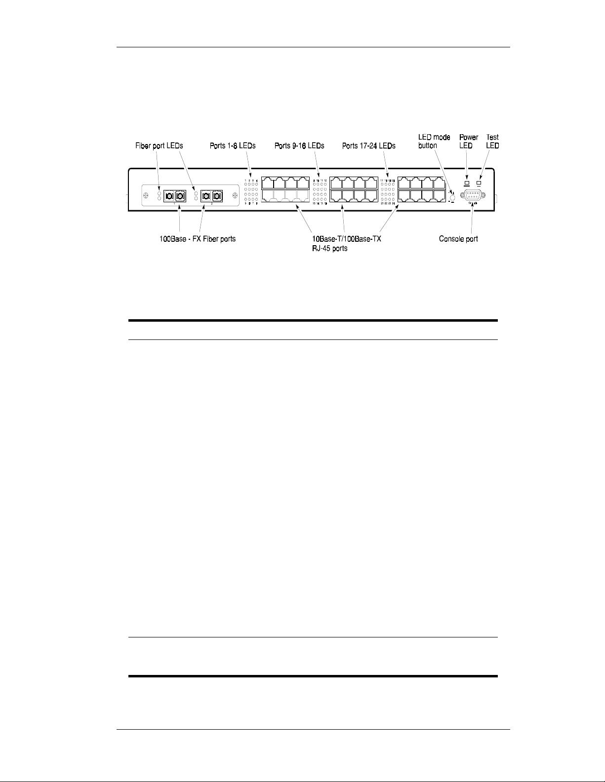
Figure 1-1 shows the front panel of the ELS100-24TXM. Table 1-1 defines
the ELS100-24TXM front panel components.
Figure 1-1. ELS100-24TXM Front Panel
Table 1-1. Front Panel Components
Name Function
100Base-FX Fiber ports
(Ports 1 and 2)*
Fiber Ports 1 and 2
LEDs*
10Base-T/100Base-TX
RJ-45 ports (Ports 1-24)*
Ports 1-24 RJ-45 LEDs* Indicates Link, Activity, Speed and Duplex information
LED mode button Button used to switch RJ-45 port LEDs between Link/
Power LED Li
Test LED Li
Console port Female DB-9 connector confi
Fiber ports usin
modules (see Table 2-3 for a list of available uplink
modules).
Indicates Link and Activity information (see Table 1-2
for details).
Copper ports usin
are wired MDI-X.
(see Table 1-2 for details).
Activity mode and 100M/Fu ll Duplex mode. This button
has no affect on fiber port LEDs.
hts steady green to indicate power is supplied to the
switch. Off indicates no power is supplied to the switch.
hts steady green after a reset and remains on until
successful completion of power-on self tests. Off indicates a successful completion of the power-on self
tests.
connection for serial out-of-band mana
the console menus.
SC fiber connectors for fiber uplink
RJ-45 port connectors. All ports
ured as a null modem
ement using
* There are 24 total ports on the ELS100-24TXM switch. When the fiber module
is installed, these ports become ports 1 and 2, used for fiber connections.
Ports 1 and 2 RJ-45 connectors then become disabled.
9032785 Product Overview 3
Page 18

Figure 1-2 shows the Link and Activity LEDs for the 2 100Base-FX ports
(fiber port LED functions are defined in Table 1-2). The LEDs are
positioned to the left of their associated port.
Link LEDs
Activity LEDs
Figure 1-2. 100Base-FX Po rt LEDs
Figure 1-3 shows the Link and Activity port LEDs for 24 10Base -T/
100Base-TX ports (defau lt configuration). When the fiber module is
installed, ports 1 and 2 RJ-45 LEDs become disabled.
Pressing the front panel LED mode button changes the operation of the
RJ-45 LEDs to 100M Speed and Full Duplex, as shown in Figure 1-4.
Link
Activity
Link
Activity
10/100 speed
Full/half duplex
10/100 speed
Full/half duplex
The numbers above and below the port LEDs identify the
LEDs associated with a specific RJ-45 port.
234
1
5678
Link
Activity
Link
Activity
9
13 14 15 16
Link
Activity
Link
Activity
18 19 20
17
21 22 23 24
10 11 12
Figure 1-3. RJ-45 Port LEDs Default Configuration
10 11 12
234
1
5678
10/100 speed
Full/half duplex
10/100 speed
Full/half duplex
9
13 14 15 16
10/100 speed
Full/half duplex
10/100 speed
Full/half duplex
17
21 22 23 24
18 19 20
Figure 1-4. Port LEDs LED Mode Button Pressed
4 Product Overview ELS100-24TXM
Page 19

The port LEDs are grouped to the left of their corresponding RJ-45 ports.
g
g
g
Table 1-2 defines the perf or m ance of the port LEDs for the 10Base -T/
100Base-TX ports in bot h the default configuration and with the LED
mode button pressed.
Table 1-2. Port LEDs Defined
Name Function
Fiber Ports Link LED On: Indicates a valid connection (link) on the associat-
ed port.
Link LED Off: Indicates no link on the associated port.
RJ-45 Ports Default Confi
tion
RJ-45 Ports
LED mode button pressed
ura-
Activity LED flashin
receive activity.
Activity LED Off: Indicates the absence of transmit or re ceive activity.
Link LED On: Indicates a vali d co nn ection (l ink) on the associa ted port.
Link LED Off: Indicates no link on the associated port.
Activity LED flashin
receive activity.
Activity LED Off: Indicates the absence of transmit or re ceive ac-
tivity.
Speed LED On: Indicates the port is in the 100Base-TX mode.
Speed LED Off: Indicates the port is in the 10Base-T mode.
Duplex LED On: Indicates the port is in the full duplex mode.
Duplex LED Off: Indicates the port is in the half duplex mode.
: Indicates the presence of transmit and/or
: Indicates the presence of transmit and/or
9032785 Product Overview 5
Page 20
Rear Panel
g
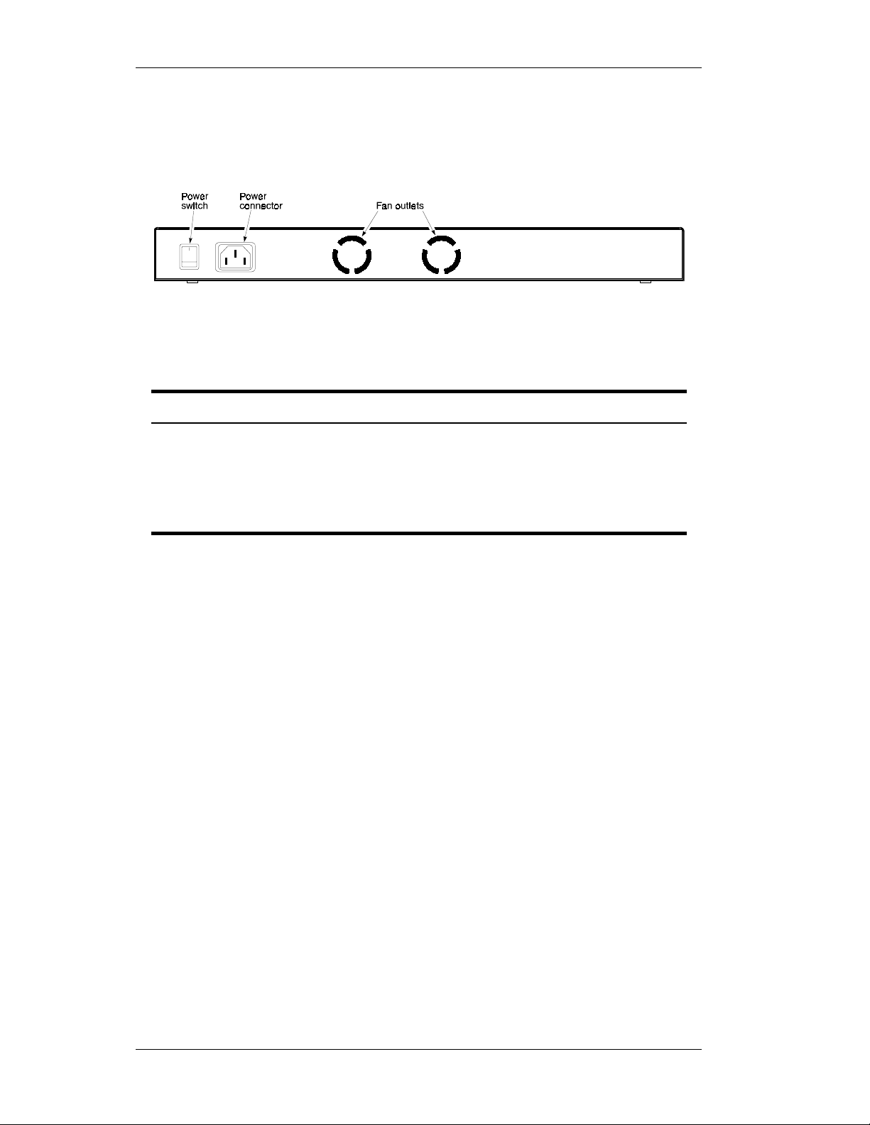
Figure 1-5 shows the ELS100-24TXM rear panel and Table 1-3 defines
the rear panel components.
Figure 1-5. ELS100-24 TXM Rear Panel
Table 1-3. Rear Panel Compone nts
Name Function
Power Connector Provides AC power to the switch.
Power Switch Allows you to tu rn the switch power on and off.
Fan Outlets Air exit vents throu
for ventilation purposes.
Feature Summaries
The following summaries provi de a brief description of ELS100 -24TXM
features in areas such as standards compliance, functionality,
performance, and options.
IEEE 802.1D Bridge
The ELS100-24TXM swit ch is fully compliant with IEEE 802 .1D
transparent bridging speci fi c at ions. An aggregate address table
containing 4096 entries per 8 switch ports is provided for learning,
filtering, and forwardi ng. The switch can support up to a maximum of
12,288 addresses. Addresses are automatically learned by the switch,
and can be individually assigned specific for warding treatment by the
network administrator if d esir ed. Forwarding table configuration can be
made out-of-band via th e console interface or in-band via SNM P or
Telnet. Static and dynamic addresses are both stored in this table. One
static address is assigned per port by def ault. The Forwarding Tabl e
Configuration screen in the console menus allows you to assign additional
static addresses if required.
h which internal fans discharge air
6 Product Overview ELS100-24TXM
Page 21

Spanning Tree Protocol
The ELS100-24TXM switch supports the IEEE 802.1D Spanning Tree
Protocol. This protocol allows redundant connections to be created
between different LAN segments for purposes of fault tolerance. Two or
more physical paths between different segments can be created through
the switch, with the Spanning Tree Protocol choosing a single path at any
given time and disabling all others. If the chosen path fails for any reason,
a disabled alternative is activated, thereby maintaining the connection.
This prevents network traffic from circulating in an endless loop formed by
multiple connections to the same LAN segment.
Spanning Tree parameters are configurable in the Spanning Tree
Configuration Menu using the console menus or via SNMP (see Appendix
B, “Spanning Tree Concepts,” for more information).
Frame Buffering and Frame Latency
The ELS100-24TXM switch is a store-and-forward switching device. Each
frame is copied into switch memory before being forwarded to another
port. This method ensures that all forwarded frames conform to a
standard Ethernet frame size and have a correct cyclic redundancy check
(CRC) for data integrity. This switching method prevents bad frames from
traversing the network and using up valuable network bandwidth, as with
cut-through switching technology.
To minimize the possibility of dropping frames on congested ports, the
ELS100-24TXM switch provides 4 MB of dynamically allocated frame
buffering per 8 ports. This buffer space is used to queue packets for
transmission on congested networ ks. This is an additional advantage
over cut-through switching technology, which drops packets immediately
when experiencing collis ions.
Software Download
The ELS100-24TXM switch suppor ts t he industry-standard Trivial File
Transfer Protocol (TFTP) for downloading software to th e s wit ch. All
switch software is stored in a 2 MB sectored flash ROM. The download
feature allows you to easily install software upgrades to the unit. Software
can alternatively be downloaded via the serial console port usi ng the
XMODEM protocol.
A TFTP or XMODEM software download is invoked via the Download
Software Me nu usi ng the conso le menu s. A TFTP dow nlo ad can al so be
invoked via SNMP.
Non-volatile Parameter Storage
Important operating param eters such as IP addresses, Spanning Tree
configuration, and manag em ent secur it y par a meters, are stored in nonvolatile Flash memory. These values are retained when the switch
experiences power interruptions or is powered down for normal
maintenance.
9032785 Product Overview 7
Page 22

Configuration and Management Interfaces
The ELS100-24TXM swit ch can be managed using any of the following
three methods:
Serial console, out-of-band
•
An RS-232 connection, using a DB-9 connector, is supported for outof-band switch management. Serial console management is performed using a terminal, or computer system running communications software. See Chapter 3, “ELS100-24TXM User Interface,” for
more detailed information on managing the ELS100- 24TXM switch
via the serial console.
Telnet, in-band (over Ethernet)
•
The switch supports management through a Telnet connection using
the TCP/IP protocols. Telnet is performed using an ASCII terminal or
computer system running communications software. See Chapter 3,
“ELS100-24TXM User I nterface,” for more detailed information on
managing the switch via the serial console. Global password protection for changing the operating parameters of the switch is provided.
SNMP-based network ma nager, in-band
•
The switch can be managed using SNMP, the most common protocol
used today for network management. Standard agent MIBs embedded in the switch provide basic SNMP management through industry-standard SNMP applications.
Management security protection is provided based on SNMP community names. See Chapter 5, “SNMP Management,” for more information.
RMON
RMON (Remote Monitoring) is a facility used to manage networks
remotely while providing multi-vendor interoperability between monitoring
devices and management stations. RMON is defined by an SNMP MI B.
This MIB is divided into nine different groups, each gathering specific
statistical information or performing a specific function. RMON-capable
devices gather network traffic data and then store them locally until
downloaded to an SNMP management station.
The ELS100-24TXM supports four of the nine groups of RMON def ined
for Ethernet networks on a per por t basi s. Specifically, these are:
Statistics: a function that maintains counts of network traffic statistics
•
such as number of packets, broadcasts, collisions, errors, and
distribution of packet sizes.
History: a function which collects historical statistics based on user-
•
defined sampling intervals. The statistical information collected is the
same as the Statistics group, except on a time stamped basis.
Alarm: a function that allows managers to set alarm thresholds based
•
on traffic statistics. Alarm s tr igger other actions throug h the Event
group.
8 Product Overview ELS100-24TXM
Page 23

Event: a function that operates with the Alarm group to define an
•
action that will be taken when an alarm condition occurs. The event
may write a log entry and/or send a trap message.
RMON Statistics group information is displayed on the Port Statistics
Screen in the console menus. Additional RMON functionality is available
via SNMP.
Port Mirroring
The ELS100-24TXM switch i ncludes the ability to mirror the traffic being
switched on any port for purposes of net work traffic analysis and
connection integrity. When this feature is enabled, a protocol analyzer or
RMON probe is connected to any port in a group of eight. This port is
configured to mirror the t ra ff ic f rom any other port in the same group of
ports. The groupings are ports 1-8, 9-16 and 17-24. You can only mirror
one port to another port at one time. Port mirroring occ urs at the same
speed configured for the port (10Mbps-to-10Mbps or 100Mbps-to100Mbps). Port mirroring is configurable in the Switch Configuration
Menu using the console menus or via SNMP.
Auto-negotiation
Auto-negotiation is a process that permits the swit ch to automatically
select the operational modes of its 10/100 RJ-45 ports. Upon first being
connected, the switch detects the speed of the network the port is
connected to, either 10Mbps or 100Mbps, and the type of communication
setting, half or full duplex. The port is then automatically set by the switch
to operate in the proper mode, without user intervention. It is not required
that the network device being connected to the switch supports autonegotiation as the ELS10 0-24TXM switch automatic al ly adjusts to the
network device’s communicati on settings. Auto-negotiation is
configurable in the Port Configuration Menu of the console menus or via
SNMP.
Broadcast Throttling
The ELS100-24TXM has the capability to throttle (or limit) the flooding of
packets through the switch. Broadcast, multicast, and unknown
destination address unicast packets received by the switch are typical ly
flooded to all ports on the switch or on a given VLAN. When the number
of these types of packets being forwarded is large, the performance of the
switch in forwarding packets of other types may suffer. A programm able
broadcast cutoff rate param eter allows a rate threshol d to be set in the
switch for the forwarding of broadcast and unknown destination address
packets. If the cutoff rate is exceeded, further packets of these types are
dropped. This capability helps to al leviate broadcast storms, a problem
often encountered in Ether net networks. Broadcast throttling is
configurable in the Swit ch Conf iguration menu of the console menus or
via SNMP.
9032785 Product Overview 9
Page 24

BootP/DHCP
The Bootstrap Protocol (BootP) and the Dynamic Host Configuration
Protocol (DHCP) provide for the capability of passing configur ation
information to hosts on a TCP/IP network. Using this process, network
devices do not need to be configured before they can communicate using
the TCP/IP protocol suite. The ELS100-24TXM switch uses BootP and
DHCP to automatically configure IP address information without requiring
access to the console menus. BootP /D HCP operation is configurable
using the BootP/DHCP Enable option in the System Configuration Menu
of the console menus or via SNMP.
LEDs
The switch port LEDs provide a quick and accurate display of the integrity
of switch connections and port mode. The default operation of the RJ-45
LEDs indicates Link (L) and Activity (A) for each of the ports. The
operation of these LEDs can be changed by use of the LED mode button
on the switch front panel. When the LED mode button is pressed (pressed
and held in), the operation of the RJ-45 LEDs changes to indicate 10/100
Mbps speed and full/half duplex operation, respectively. The fiber port
LEDs indicate Link (L) and Activity (A) for each of the ports. The fiber port
LEDs are not affected by the LED mode button.
Full Duplex Mode
The full duplex mode of operation on a port can double the throughput of
switch connections. This mode disables the collision detection portion of
the Ethernet Carrier Sense Multiple Access with Coll ision Detection
(CSMA/CD) protocol, allowing for two-way traffic. Full dupl ex is
configurable using the Duplex Mode par am eter in the Port Menu of the
console menus or via SNMP.
Flow Control
Flow control allows you to manage network traffic during con gestion
periods and to prevent the loss of packets when port buffer thresholds are
exceeded. Flow control also serves to deny access to additional traffic
that could add to a congestion condition. The ELS100-24TXM switch
supports flow control per th e IE EE 802.3x standard. See Appendix C,
“Flow Control,” for more information on this feature.
Virtual LANs (VLANs)
VLANs allow you to connect users to a specific LAN segment regardless
of their physical location. The ELS100-24TXM switch supports tagged
VLANs per the IEEE 802.1Q draft standard. With fram e tagg ing, a short
tag is appended to every frame that crosses the network backbone. The
tag identifies which VLAN the frame belongs to. See Appendix D, “Virtual
LANs,” for more inform ation.
10 Product Overview ELS100-24TXM
Page 25

Class of Service
Class of Service support allows you to assign a higher priority to selected
traffic passing through the switch. The ELS100-24TXM switch supports
Class of Service attributes per the IEE E 802.1p draft standard using a
priority queuing mechanism. This feature ensures that tr af fic during
congestion periods will not interfere with traffic assigned a higher priority.
Traffic assigned a lower priority is subj ect to discard when memory is in
short supply. See Appendix E, “ Cl ass of Service,” for more infor m ati on.
Application Examples
The exploding popularity of the Internet and of corporate intranets, as well
as new, high-bandwidth desktop applications, are driving the demand for
Fast Ethernet. The increase in multimedia traffic and the need to support
legacy protocols alongside new, data intensive applications is driving the
need for network segmentat ion and traffic prioritizati on.
The ELS100-24TXM switch is ideal for meeting the needs of today’s high
performance networks. The switch’s low cost and high port count makes
it attractive and affordabl e for dedicated 10/100Mbps connections to the
desktop. In addition, extensive features, including redundant links, traffic
Class of Service and VLAN capability, provide the management needed
for the workgroup and local backbone.
The following sections illustrate the ELS100-24TXM switch employed in
application examples:
Client/Server Network
•
Local Backbone
•
9032785 Product Overview 11
Page 26
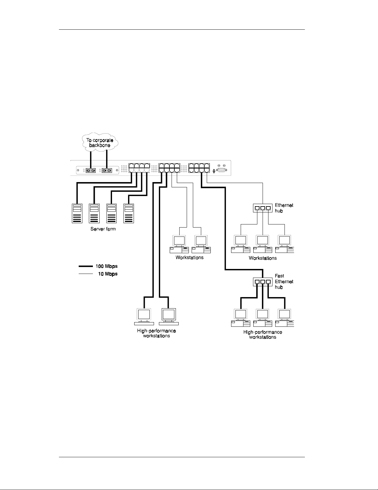
Client/Server Network Application
To improve workstation per for m ance in a client/server environment, the
ELS100-24TXM switch can be configured to provide 200 Mbps full duplex
Fast Ethernet connections to servers by connecting each to a dedicated
switch port (Figure 1-6). Users can be accommodated through
connections to hubs, both at 10Mbps and 100M bps speeds, through
10Mbps switches with 100Mbps uplinks, or thr ough direct connections.
The fiber uplinks are available to connect the switch to a remote location,
such as another building floor or a separate building.
Figure 1-6. Client/Server Ne twork Applicat io n
12 Product Overview ELS100-24TXM
Page 27
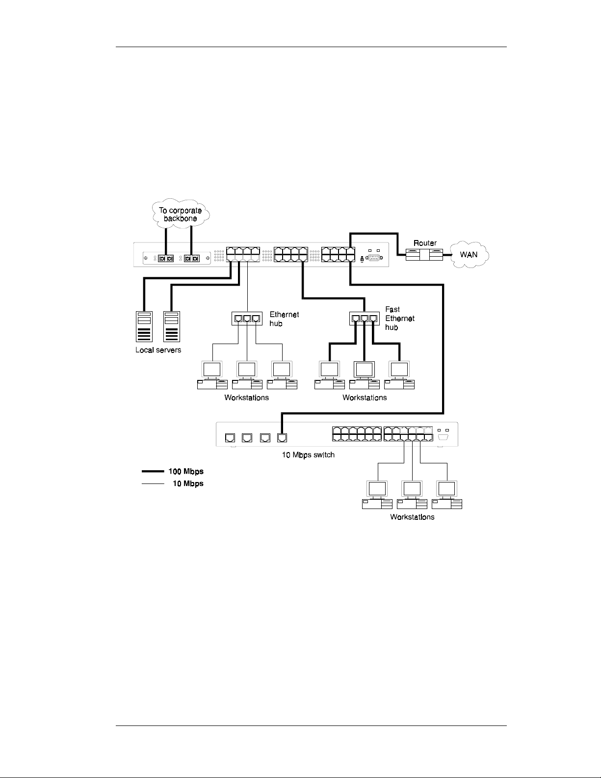
Local Backbone Application
The ELS100-24TXM switch can be used in a local backbone application,
connecting network segments together and providing file-server access
(Figure 1-6). Workgroup hubs are provided with a single connection to the
switch while servers are put on dedicated 100 Mbps ports. Routers and
other networking devices can connect of f of the switched backbone as
well. The fiber uplinks are available to connect the switch to a remote
location, such as another building floor or a separate buil ding.
Figure 1-7. Local Backbone Appli cat ion
9032785 Product Overview 13
Page 28

Page 29

2. INSTALLATION
Inspecting Your Shipment
When you receive the shipment of your switch, check the package
contents and make sure you have the following items:
•
ELS100-24TXM Fast Ethernet switch
•
Fiber port protective plugs inserted into switch
•
Mounting ears and mounting screws
•
Power cord
•
This document
Site Requirements
Before you install the switch, make sure the site meets the following
requirements:
•
Mounting
Provide a flat table, wall or shel f sur face, or an optional 19 in. (48.3
cm) equipment rack.
Use an EIA standard equipment rack that is grounded and physically
secure.
•
Power source
Provide a power source within six feet (1.8 m) of the installation loca-
tion. This source must provide 100 VAC to 240 VAC, and 50 Hz to 60
Hz power, with a 100 VA minimum. Power specifications for the
switch are shown in Appendix A, “Specifications.”
Primary voltage selection within the above ranges is
automatic and requires no user action.
•
Environmental
Install the ELS100-24TXM switch in a dry area, with adequate air cir-
culation. Avoid placing the switch in direct sunlight or near other heat
sources, such as hot-air vents. For temperatur e and humidity specifications, see Appendix A, “Sp e cif ications.”
•
Ventilation
Do not restrict airflow by covering or obstructing air inlets on the side
of the switch or the rear panel in ternal air fan exits.
9032785 Installation 15
Page 30

Mounting the Switch on a Table or Shelf
Mount the switch on a table or shelf in a position whi ch allows access to
the front panel RJ-45 ports, visi bility of the port LEDs, and access to the
power cord. Make sure that the mounting surface can safely support the
switch and that there is adequate space around the switch for ventilation
and cooling.
16 Installation ELS100-24TXM
Page 31

Mounting the Switch on a Wall
The switch ships with two (2) mul ti -position mounting ears and four (4)
mounting screws.
The mounting screws are used to attach the mounting ears to
the switch. Once the ears are attached to the switch, you will
need to provide appropriate screws to mount the switch to the
wall.
Figure 2-1 shows the orientation of the m ount ing ears for attaching the
ears to the switch for a wall mount application. Be sure that the wall
surface can safely support the switch.
Do the followi n g:
1.
Mount one of the ears to the switch using two (2) of the supplied
screws. Repeat this step for t he other side of the switch.
2.
Mount the switch to the wall using appr opriate screws.
Figure 2-1. Mounting the Switch on a Wall
9032785 Installation 17
Page 32

Mounting the Switch in a Rack
The switch ships with two (2) multi-position mounting ears and four (4)
mounting screws.
The mounting screws are used to attach the mounting ears to the switch. Once the ears are attached to
the switch, you will need to provide appropriate
screws to mount the switch in a rack.
Figure 2-2 shows the orientation of the mounting ears for attaching the
ears to the switch for a rack mount application. Mount the switch with the
front panel facing forward. Do the following:
1.
Mount one of the ears to the swit ch using two (2) of the supplied
screws. Repeat this step for the ot her side of the switch.
2.
Slide the switch into the rack and align the holes in the rack mounting
ears with the holes in the rack rai ls.
3.
Insert and tighten appropri ate rack-mounting screws (not provided).
Figure 2-2. Mounting the Switch in a Rack
18 Installation ELS100-24TXM
Page 33

Installing a Fiber Uplink Module into the Switch
The fiber uplink module op ti on permits you to enable 100Bas e- FX fiber
connections to the switch. A 2 port fiber module can be installed into the
modular slot on the left side of the switch (Figure 2-3).
To install the fiber module into the switch, do the following:
1.
Turn off power to the switch.
2.
Remove the blank metal pla te f rom the left side of the switch by
unscrewing the two mounting screws.
3.
While maintaining a firm grip on the fiber connectors, insert the fiber
module card into the modular slot, with the module components
facing upwards. Insert the module into the slot uniformly. There are
no card guides. The connector on the fiber module mates with the
connector inside the switch. Press firmly until the module is properly
seated.
Figure 2-3. Installing a Fiber Module into the Switch
4.
Position the mounting plate (shipped with the fiber module) over the
port connectors and align the mounting plate hole with the modular
port holes.
5.
Insert the 2 mounting screws and fasten.
6.
Turn on power to the switch.
9032785 Installation 19
Page 34

Connecting a Terminal to the Console Port
The console port is a serial RS-232 interface port that enables a
connection to a terminal for performing switch monitoring and
configuration functions. The terminal may be a PC or workstation running
terminal emulation softw are, or a dumb terminal configured as a Data
Terminal Equipment (DTE) connection. Alternatively, this port can be
connected to an external modem t o enable remote dial-in managem ent .
If you connect a terminal to the console port prior to powering the switch,
you can observe the progress and results of the power-up diagnostics as
the switch goes through its initialization process.
The console port connector is configured as a female null modem
connection using a female DB-9 ( see Table A-1 for pinouts). A standard
straight-through wired R S- 232 cable is typically all that is neede d to
connect to this interface . Any cable connected to the console port must
be shielded to comply with emissi ons regulations and requirements.
To connect the ELS100-24TXM console por t to a terminal, do the
following:
1.
Connect a terminal to the console port using an interface ca ble
(Figure 2-4).
Figure 2-4. Connecting a Terminal to the Console Port
2.
Connect the male connecto r of the in terface cable directly to the
switch console port and tighten the capti v e retaining screws.
3.
Connect the other end of th e interface cable to a terminal (i n some
instances, an adapter may be required to make this connection).
4.
From your terminal, start the te rminal emulation program.
20 Installation ELS100-24TXM
Page 35

Configure the terminal to the following communication settings: 9600
5.
baud, no parity, 8 data bits, 1 stop bit, no hardware flow control,
ASCII character set.
Powering the Switch
To supply power to the switch, do the fol lowing:
Connect the power cord to the switch and to a grounded three-prong
1.
wall outlet (Figure 2-5) . See Appendix A, “Power Cord Set
Requirements,” for more information regarding specific international
power cord requireme nts.
Figure 2-5. Connecting the Power Cord to the Switch
Turn on the power switch.
2.
The Power LED lights green (see Figure 1-1). If it does not, check to
make sure that the power cable is plugged in correctly and that the
power source is good.
Power-Up
When you turn the power on, the switch cond uct s a series of har dw are
and software tests to verify correct operation. If a terminal or computer is
connected to the console port, the results of the tests are displayed on the
screen. If you want to display the results of the tests after the switch has
already been turned on, turn the power switch off and then back on.
The switch performs two basic types of tests at power-up. During this
time, the Test LED (see Figure 1-1) lights steady green. These tests are:
Serial port
•
The serial console port test is the first test performed. If the switch
fails this test, no further tests are performed, and the console displays
no information.
9032785 Installation 21
Page 36

Memory
g
g
g
•
Memory tests on the CPU RAM are performed after the serial port
test. No results are displayed on the console.
After these two tests are performed, the operational software of the switch
is loaded. A series of more extensive diagnostic tests are then conducted
during which the Test LED remains lit. The results of the tests are
displayed on the terminal. If all tests pass, the Test LED turns off. When
all tests are complete, the system is functional and the user interface is
ready to receive commands at the console.
Network Cable Requirements
Copper
Table 2-1 specifies the cable types and length constraints for the copper
interfaces on the ELS100-24TXM.
Table 2-1. Copper Cable Specif ic ations
Interface Type Cable Requirement Maximum Length
10Base-T Cate
100Base-TX Cate
ory 3 or 5 Unshielded Twisted
Pair (UTP)
ory 5 UTP 100m (328 ft.)
100m (328 ft .)
Fiber
Table 2-2 specifies the fiber types and length constraints on the
ELS100-24TXM.
Table 2-2. Fiber Specifi cations
Interface Type Fiber Type Fiber Diameter
100Base-FX multi-mode 62.5 2,000m (6,560 ft.)
100Base-FX sin
le-mode 9 20,000m (65,600 ft.)
(microns)
Maximum Length
22 Installation ELS100-24TXM
Page 37

10Base-T/100Base-TX Ports
The 10Base-T/100Base-TX ports use RJ-45 connectors. Figure 2-6
shows an RJ-45 connector being inserted into a port.
Figure 2-6. Inserting an RJ-45 Connector into a Port
The 10Base-T/100Base-TX ports interface to UTP cabling for connection
to 10Base-T or 100Base-TX network segments or end-stations. These
UTP connections meet the requirements of ISO 8877, specified by
10Base-T, Section 14 of the IEEE 802.3 specification. The ports are wired
with the MDI-X function implemented. Workstations or servers can be
connected to the ELS100-24TXM switch using standard straight-through
wired cables.
For connections to hubs or other swit ches, a crossover cable may be
necessary (refer to the “MDI/MDI-X Crossover Cable Wiring” section in
Appendix A). See Table A-2 fo r 10Base-T/100Base-TX connector pin
assignments.
9032785 Installation 23
Page 38

100Base-FX Fiber Ports
g
g
g
g
The 100Base-FX Fiber ports use SC connectors. Figure 2-7 shows an SC
fiber connector being insert ed into a fiber port on the ELS100-24TXM.
Figure 2-7. Inserting an SC Fiber Con nect or into a Fiber Port
Depending on the fiber uplink module employed (see Table 2-3), these
ports support either multi- mode 62.5/125µm fiber or single-mode 9/
125µm fiber. The 100Base-FX ports use SC fiber connectors. The SC
fiber connectors are configured as a receive (RX)/transmit( TX) pair with
the RX connector positioned on the left side of the port and the TX
connector on the right side of the port.
Fiber Uplink Modules
Table 2-3 provides information for the three different 2 port fiber uplink
modules (daughtercards) available for the ELS100-24TXM.
Table 2-3. Fiber Uplink Modules
Part Number Functions Description
EPIM100-2F2 100Base-FX-MM
100Base-FX-MM
EPIM100-2F3 100Base-FX-SM
100Base-FX-SM
2 port multimode (M M) fiber uplink module
SC fiber connectors.
usin
2 port sin
usin
lemode (SM) f ibe r upl ink modu le
SC fiber connectors.
EPIM100-2F4 100Base-FX-SM
100Base-FX-MM
24 Installation ELS100-24TXM
2 port (1 SM and 1 MM) fi ber upli nk module
usin
SC fiber connectors.
Page 39

3. ELS100-24TXM USER INTERFACE
Overview
When you have connected a terminal to the console port, or used Telnet
to access the switch over the network, access is gai ned to the console
menus. These menus allow you to reconfigure the switch from its factory
default settings, as well as to monitor switch status and performance. The
menus have a layout similar to the sample Main Menu shown in Figure 3-
1. The information is divi ded into the following parts:
•
Menu Identification (i ncludes model number)
•
Menu Name (includes access privileges)
•
Selectable Items listed by letters
•
Screen Prompt for menu selections an d entr y of fie ld par am et ers,
and Message Area for display of next entry opt ion, parameters, or
error messages.
Menu ID
Menu name
Selectable
items
Screen prompt
and message
area
Cabletron Systems E LS100-24TXM Access Control: READ/WRITE
MAIN MEN U
a. System Conf ig uration Me nu
b Switch Configurat io n Menu
c. Port Menu
d. Switch Stati s tics Screen
e. General Information Screen
f. Download Software Menu
g. Save Current Conf iguration
h. Return to Default Configuration
i. Logout
j. Reset
Enter Selection:
Figure 3-1. Sample Main Menu
9032785 ELS100-24TXM User Interface 25
Page 40

User Access
There are two modes of access to the user interface: READ-ONLY and
READ/WRITE. READ-ONLY access allows you to view switch
information, but not modify any operating parameters. READ/WRITE
access allows you to both read and modify switch information. You are
required to login with a password before obtaining READ/WRITE access.
If no password is entered (press only the [Enter] key), you are logged in
with READ-ONLY access.
default settings, allowing full READ/WRITE access until a password is
set.
To use the console menus, do the following:
1.
Type the letter associated with the desired option.
If the selected item is a submenu ti tle, the submenu is displayed
when you enter the letter.
2.
Enter the parameter requested by the screen prompt.
If the selected item is a parameter, the system displays a prompt for the
entry of a new parameter value . If the value entered is invalid, a beep
sounds, or a message displays, requesting you to enter a valid value.
No password is configured in the factory
26 ELS100-24TXM User Interface ELS100-24TXM
Page 41

Factory Defaults
ging
g
g
g
g
g
Table 3-1 lists the factory default settings for the switch configurati on
parameters. Each of these para meters can be changed via the console
menus or Telnet.
Table 3-1. Factory Default Settings
Parameter Default Value
Active A
Auto-ne
Broadcast Cutoff Rate 500000
BootP/DHCP Enable Yes
Brid
e Priority 32768
Class of Service Enable No
Class of Service Port Priority 0
Class of Service Priority
Threshold
Flow Control Enable No
Forward Delay 15
Full Duplex Yes
Hello Time 2
Max A
Password <none>
Path Cost 10 for 100Mbps s peed ports
Time 300
otiation Enab le Yes
4
e20
100 for 10Mbps speed ports
Port Enable Yes
Port Priority 128
Port Speed 100
Port Mirrorin
Screen Timeout 0
SNMP Private Community Name private
SNMP Public Community Name public
Spannin
Terminal Baud Rate 9600
Terminal Hard w ar e Flo w C ont rol No
VLAN Enable No
VLAN Port Type Access
9032785 ELS100-24TXM User Interface 27
Enable No
Tree Protocol Enable No
Page 42

Menu Hierarchy
Figure 3-2 shows the ELS100- 24TXM switch user interface menu
hierarchy.
System
Configuration
Menu
Switch
Configuration
Menu
Port Menu
Switch
Statistics
Screen
General
Information
Screen
SNMP Configuration Menu
System Name
System Location
System Contact
IP Address
Subnet Mask
Default Gateway
BootP/DHCP Enable
Screen Timeout (minutes)
Password
Terminal Baud Rate
Forwarding Table Configuration Menu
Spanning Tree Configuration Menu
VLAN Configuration Menu
Class of Service Configuration Menu
Forwarding Table Aging Time (seconds)
Broadcast Cutoff Rate
Port Mirroring Enable
Mirrored Port
Mirroring Port
ID
Port Name
Enable Status
Link Status
Auto Negotiated Status
Full Duplex Status
Speed (10/100Mbps)
Port Type
Flow Control
Configure
ID
Transmitted
Received
Forwarded
Filtered
Dropped
Errored
Switch Summary
Port Statistics
Software Version
Serial Number
Base MAC Address
Up Time (minutes)
Power Up Count
SNMP Private Community Name
SNMP Public Community Name
Trap Destination #1-4
Community Name #1-4
Display Table
Make Entry Static
Add Static Entry
Delete Static Entry
Modify Static Entry
Search by Port#
Search by MAC Address
Spanning Tree Protocol Enable
Port Configuration Menu
Hello Time (seconds)
Forward Delay (seconds)
Max Age (seconds)
Bridge Priority
VLAN Enable
VLAN Menu
VLAN Port Menu
Class of Service Enable
Priority Threshold
Configure Port Priority
Port Name
Port Enable
Flow Control Enable
Auto-negotiation Enable
Full Duplex
Port Speed
Frames Transmitted
Frames Received
Frames Forwarded
Frames Filtered
Frames Dropped
Frames Errored
Port #n Statistics
Port ID
Port Name
Path Cost
Port Priority
Port State
Select Port
ID
VLAN Name
Ports in VLAN
VLAN Egress Ports
Configure
Port ID
Port Name
Type
Modify Port Type
Port ID
Port Name
Priority Default
Configure
Download Software Menu
Save Current Configuration
Return to Default Configuration
Logout
Reset
Frames Transmitted Collisions
Frames Received Late Collisions
Frames Forwarded CRC/Alignment Errors
Frames Filtered Undersized Frames
Frames Dropped Oversized Frames
Broadcasts Transmitted Fragments
Broadcasts Received Jabbers
Multicasts Transmitted 64 Byte Frames
Multicasts Received 65 to 127 Byte Frames
Bytes Transmitted 128 to 255 Byte Frames
Bytes Received 256 to 511 Byte Frames
Pause Frames Transmitted 512 to 1023 Byte Frames
Pause Frames Received 1024 to 1518 Byte Frames
Figure 3-2. ELS100-24TXM User Interface Menu Hierarchy
28 ELS100-24TXM User Interface ELS100-24TXM
Page 43

Main Menu
g
g
g
g
g
g
g
g
g
g
g
g
g
g
g
g
g
g
The Main Menu is the first screen seen after successfully logging in to the
system. Figure 3-3 shows the Main Menu and the accompanying ta ble
describes the Main Menu.
MAIN MENU Access Control: READ/WRITE
a. System Configuration Menu
b Switch Configuration Menu
c. Port Menu
d. Switch Statistics Screen
e. General Information Screen
f. Download Software Menu
g. Save Current Configuration
h. Return to Default Configuration
i. Logout
j. Reset
x. Previous Menu
Enter Selection:
Figure 3-3. Main Menu
Selection Description
System
uration Menu
Confi
Switch
Confi
uration Menu
Port Menu Shows the confi
Switch Statistics
Screen
General Information Screen
Download Software
Menu
Save Current
uration
Confi
Return to Default
Configuration
Contains commands and parameters that reflect the
uration of the switch related to management.
confi
Provides access to informa tion and paramet ers affectin
function of the switch, i. e. the m ovement of packet s throu
the switch. For example, you can c onfi
ble, Spannin
Tree, and virtual LANs (V LAN s) .
and allows you to modify switch port operation.
Presents switch-level and port-level statistics.
Displays the system software version, switch serial number,
base MAC address, system up time and power-up count.
Contains paramete rs and commands for initiatin
download to up
Saves current switch operatin
memory.
Restores switch operatin
You must reset the switch for activate default parameters.
lobal
the
h
ure Forwarding Ta-
uration of the i ndividual p orts on the switch
a software
rade the switch operating software.
parameters to non-volatile
parameters to factory defaults.
Lo
out Logs out of the console inter face. Once you logout, you must
enter a password before you can access the console interface a
Reset Performs a software reset of the switch by restartin
tem software and reloadin
9032785 ELS100-24TXM User Interface 29
ain.
the sys-
all operating parameters.
Page 44

System Configuration Menu
g
g
g
g
g
g
The System Configuration Menu enables modif ication of system-level
switch configuration parameters. Select a from the Main Menu to view the
System Configuration Menu. Figure 3-4 shows the System Configuration
Menu and the accompanying table descr ibes the System Configurat ion
Menu.
SYSTEM CONFIGURATION Access Control: READ/WRITE
a. SNMP Configuration Menu
b System Name
c. System Location
d. System Contact
e. IP Address 000.000.000.000
f. Subnet Mask 000.000.000.000
g. Default Gateway 000.000.000.000
h. BootP/DHCP Enable Yes
i. Screen Timeout (minutes) 0
j. Password None
k. Terminal Baud Rate 9600
l. Terminal Hardware Flow Control No
x. Previous Menu
Enter Selection:
Figure 3-4. System Configuration Menu
Selection Description
SNMP Confi
System Name The switch administrative name (1-36 character range).
System Location The physical switch location (1-36 character range).
System Contact The switch contact person (1-36 character range).
IP Address The IP address of the switch.
Subnet Mask Subnet mask associated with the switch IP address.
Default Gateway The default gateway (or router) to which the switch sends
BootP/DHCP Enable Allows you to enable (Yes) or disable (No) the BootP and
Screen Timeou t (minutes) The duration of time before a seri al console or Teln et
Password Allows “read/write” access to the user interface, via the
Terminal Baud Rate Serial console baud rate (2400, 9600 or 19200).
Terminal Hardware Flow
Control
uration Menu Menu for configuring SNMP-related parameters.
IP packets destined for a different subnet.
DHCP protocols for automatically confi
uring the
switch’s IP address information.
session terminates due to user inactivity (0-65535 numeric ran
e). A value of “0” means that the screen will
not terminate at any time.
serial console or Telnet (1-10 character ran
e).
Allows you to en able (Yes) or d isable (No) h ardware flow
control on serial console interface. Si
nals DTR, RTS
and CTS are used for this purpose. Flow control should
be enabled if usin
external modem.
30 ELS100-24TXM User Interface ELS100-24TXM
Page 45

SNMP Configuration Menu
g
g
g
g
g
g
The SNMP Configuration Menu allows you to modify SNMP-related
configuration parameters. Sel ect a from the System Configuration Menu
to view the SNMP Configurat ion Menu. Figure 3-5 shows the SNM P
Configuration Menu and accompanying table describes the SNMP
Configuration Menu.
SNMP CONFIGURATION Access Control: READ/WRITE
a. SNMP Private Community Name private
b. SNMP Public Community Name public
c. Trap Destination #1 000.000.000.000
d. Community Name #1 public
e. Trap Destination #2 000.000.000.000
f. Community Name #2 public
g. Trap Destination #3 000.000.000.000
h. Community Name #3 public
i. Trap Destination #4 000.000.000.000
j. Community Name #4 public
x. Previous Menu
Enter Selection:
Figure 3-5. SNMP Configuration Menu
Selection Description
SNMP Private
Community Name
SNMP Public
Community Name
Trap Destination #1 The IP address of trap destination #1 wher e SNMP trap mes-
Community Name #1 The SNMP community na me to use for traps forwarded to trap
Trap Destination #2 The IP address of trap destination #2 wher e SNMP trap mes-
Community Name #2 The SNMP community na me to use for traps forwarded to trap
Trap Destination #3 The IP address of trap destination #3 wher e SNMP trap mes-
Community Name #3 The SNMP community na me to use for traps forwarded to trap
Trap Destination #4 The IP address of trap destination #4 wher e SNMP trap mes-
The community name for read/write SNMP access to the
device (1-10 character ran
e; the default name is: “private”).
The community name for read only SNMP access to the device (1-10 character ran
es are forwarded.
sa
e; the default name is: “public”).
destination #1.
es are forwarded.
sa
destination #2.
sa
es are forwarded.
destination #3.
es are forwarded.
sa
Community Name #4 The SNMP community na me to use for traps forwarded to trap
destination #4.
9032785 ELS100-24TXM User Interface 31
Page 46

Switch Configuration Menu
g
g
g
g
g
g
g
g
g
g
g
g
g
g
g
The Switch Configuratio n Menu allows you to modify switchi ng- related
configuration parameters. Select b from the Main Menu to view the Switch
Configuration Menu. Fig ure 3-6 shows the Switch Configur at ion Menu
and the accompanying table describes the Switch Configuration Menu.
SWITCH CONFIGURATION Access Control: READ/WRITE
a. Forwarding Table Configuration Menu
b. Spanning Tree Configuration Menu
c. VLAN Configuration Menu
d. Class of Service Configuration Menu
e. Forwarding Table Aging Time(seconds) 300
f. Broadcast Cutoff Rate 500000
g. Port Mirroring Enable No
h. Mirrored Port 2
i. Mirroring Port 1
j. Transmit Data Mirror Enable Yes
k. Receive Data Mirror Enable No
x. Previous Menu
Enter Selection:
Figure 3-6. Switch Configuration Menu
Selection Description
Forwardin
Confi
Spannin
Table
uration Menu
Tree Configuration
Menu
VLAN Confi
Class of Service Confi
uration Menu Menu for configuring the VLAN operation of the switch.
uration
Menu
Forwardin
Table Aging Time Time in seconds until entries in the filter table are aged
Broadcast Cutoff Rate Per second rate past which broadcast and destination
Port Mirrorin
Enable Allows you to enable (Ye s) or di sab le ( N o) port mirror-
Mirrored Port The source port for the data to be mirrored.
Mirrorin
Port The destination port for the data to be mirrored.
Transmit Data Mirror Enable * Allows you to enable (Yes) or disable (No) the mirror-
Receive Data Mirror Enable * Allows you to enable (Yes) or disable (No) the mirror-
* Only one of these options can be enabled at any given time. Changing the setting
of one of these options automatically changes the setting of the other option.
Menu for confi
uring the switch forwarding table.
Menu for configuring the switch Spanning Tree
operation.
Menu for configuring Class of Service for the switch.
out if not accessed (10-1,000,000 second ran
e).
unknown unicast frames a r e not flooded on each
roup of 8 ports on the switch (100-500,000 frames per
second ran
.
in
of data transmitted out the mirrored port.
in
in
of data received by the mirrored port.
e).
32 ELS100-24TXM User Interface ELS100-24TXM
Page 47

Forwarding Table Configuration Menu
g
g
g
g
The Forwarding Table Configuration Menu allows you to view and modify
forwarding table parameters. The MAC address of each forwarding table
entry is displayed along with its type, disposition, and associated port
number. Select a from the Switch Configuration Menu to view the
Forwarding Table Configuration Menu. Figure 3-7 shows the Forwarding
Table Configuration Menu and the accompanying table describes the
Forwarding Table Configuration Menu.
FORWARDING TABLE CONFIGURATION Access Control: READ/WRITE
MAC ADDRESS TYPE DISPOSITION PORT ID PORT NAME
-------------------------------------------------------------------------------------------------------------------- 0a0a0a0a0a0b DYNAMIC FORWARD 1
0a0a0a0a0a0b DYNAMIC FORWARD 2
0a0a0a0a0a0c DYNAMIC FORWARD 3
0a0a0a0a0a0d DYNAMIC FORWARD 4
0a0a0a0a0a0e DYNAMIC FORWARD 5
0a0a0a0a0a0f DYNAMIC FORWARD 6
0a0a0a0a0a10 DYNAMIC FORWARD 7
0a0a0a0a0a11 DYNAMIC FORWARD 8
n. Next Page p. Previous Page f. First Page l. Last Page
a. Display Table b. Make Entry Static
c. Add Static Entry d. Delete Static Entry e. Modify Static Entry
s. Search by Port # m. Search by MAC Address x. Previous Menu
Enter Selection:
Figure 3-7. Forwarding Table Conf iguration Menu
Field De scr ip ti o n
MAC Address MAC address for th e listed port.
Type Displays the type of address en try: syst em, d yna mic or sta t-
ic.
Disposition Displays disposition of the address entry: local, forward or
discard.
Port ID Displays the port number associa ted with the MAC address
entry.
Port Name Displays the administrative name assi
Selection Description
Next Page Displays the next page of the forwarding table.
ned to the port.
Previous Pa
First Pa
Last Pa
e Displays the previous page of the forwarding table.
e Displays the first page (top) of the forwarding table.
e Displays the last page of the forwarding table.
continued on next page
9032785 ELS100-24TXM User Interface 33
Page 48

Selection Description
g
Display Table Redisplays the forwardin
table.
Make Entry Static Makes a dynamic entry in the forwarding table static.
Add Static Entry Adds a static entry to the forwarding table.
Delete Static Entry Deletes a static entry from the forwarding table.
Modify Static Entry Modifies a static entry from the forwarding table.
Search by Port # Performs a search by port numb er and posts the search re-
sults at the top of the screen.
Search by MAC Address
Performs a search by MAC Address a nd po sts the search results at the top of the screen.
34 ELS100-24TXM User Interface ELS100-24TXM
Page 49

Spanning Tree Configuration Menu
g
g
g
g
g
g
g
g
The Spanning Tree Config ur ation Menu allows you to view and modi fy
Spanning Tree parameters. Select b from the Switch Configuration Menu
to view the Spanning Tree Configur ation Menu. A letter identifies
selections that can be modified. All other fields are read-only. Figure 3-8
shows the Spanning Tree Configuration Menu and the accompanying
table describes the Spanning Tree Configuration Menu.
SPANNING TREE CONFIGURATION Access Control: READ/WRITE
Bridge ID 32768-000000000000
Designated Root
Root Path Cost 0
Root Port NO PORT
Topology Change Count 0
a. Spanning Tree Protocol Enable No
b. Port Configuration Menu
c. Hello Time (seconds) 2
d. Forward Delay (seconds) 15
e. Max Age (seconds) 20
f. Bridge Priority 32768
x. Previous Menu
Enter Selection:
Figure 3-8. Spanning Tree Configuration Menu
Field Description
e ID A unique identifier for the bridge (switch) in the Span-
Brid
Tree. The ID is a combinatio n of the bridge priority
nin
and port 1 MAC address.
Desi
nated Root The bridge in the Spanning Tree with the lowest Bridge
ID value, desi
Root Path Cost The cost of the path to the root brid
Root Port The port identifier of t he por t t ha t off er s th e low e st cost
path to the root brid
Topolo
y Change Count The cou nt o f th e n um be r of times the network topo logy
has chan
nated as the root bridge.
e.
e.
ed from a Spanning Tree reconfiguration.
continued on next page
9032785 ELS100-24TXM User Interface 35
Page 50

Selection Description
g
g
g
g
g
g
g
g
g
g
Spannin
Enable
Port Confi
Tree Protocol
uration Menu Provides access to the Spanning Tree Port Configura-
Allows you to enable (Yes) or disable (No) the global
Spannin
Tree operation on the switch.
tion Menu.
Hello Time (seconds) The time interval betwee n the se nd i n
BPDUs by the brid
e, if it is root (1-10 second range).
of Configuration
Forward Delay (seconds) The time interval delay before a port transfers into the
forwardin
Max A
e (seconds) The maximum age of received protocol information be-
fore it is discarded (6-40 second ran
Brid
e Priority A relative priority of bridges, with the lowest value bridge
ID indicatin
state, if it is root (4-30 second range).
e).
the highest priority (0-65535 range).
36 ELS100-24TXM User Interface ELS100-24TXM
Page 51

Spanning Tree Port Configuration Menu
g
g
g
g
g
g
g
g
g
g
g
The Spanning Tree Port Configuration Menu allows you to view Spanning
Tree Configuration information for all of the ports in a table format. Select
b
from the Spanning Tree Configuration Menu to view the Spanning Tree
Port Configuration Menu. Figure 3-9 shows the Spanning Tree Port
Configuration Menu and the accompanying table describes the Spanning
Tree Port Configuration Menu.
SPANNING TREE PORT CONFIGURATION Access Control: READ/WRITE
PORT ID PORT NAME PATH COST PORT PRIORITY PORT STATE
-------------------------------------------------------------------------------------------------------- 1 10 128 FORWARDING
2 10 128 FORWARDING
3 10 128 FORWARDING
4 10 128 FORWARDING
5 10 128 FORWARDING
6 10 128 FORWARDING
7 10 128 FORWARDING
8 10 128 FORWARDING
9 10 128 FORWARDING
10 10 128 FORWARDING
n. Next Page p. Previous Page f. First Page l. Last Page
a. Select Port r. Refresh x. Previous Menu
Enter Selection:
Figure 3-9. Spanning Tree Port Configuration Menu
Field Description
Port ID A unique identifier for a port on the brid
Port Name The administ rative name assi
ned to the port.
Path Cost The contribution of the path throu
to the total pat h cost from this b rid
ports, 100 for 10Mbps ports.
Port Priority The relative priority of the port on the brid
Port State The current Spannin
abled, listenin
Tree state of the port on the bridge, either dis-
, learning, forwarding, or blocking.
Selection Description
Next Page Displays the next page of the tabl e.
Previous Pa
e Displays the previous page of the table.
e (switch).
h this port, when it is the root port,
e to the root bridge. 10 for 100Mbp s
e.
First Pa
Last Pa
e Displays the first page (top) of the table.
e Displays the last page of the table.
Select Port Allows you to enter a port number to view a nd modify port par ameters
in the Spannin
9032785 ELS100-24TXM User Interface 37
Tree Port #n Configuration Menu.
Page 52

Spanning Tree Port #n Configuration Menu
g
g
g
g
g
g
g
g
g
The Spanning Tree Port #n Confi guration Menu allows you to view
Spanning Tree Port Configuration information for an individual port.
Select a from the Spanning Tree Por t C onfiguration Menu to view the
Spanning Tree Port #
Spanning Tree Port #
describes the Spanning Tree Port #
designation represents the speci f ic port number for configurat ion.
SPANNING TREE PORT #1 CONFIGURATION Access Control: READ/WRITE
Port State DISABLED
MAC Address 000000000000
Designated Cost 0
Designated Port 0
Designated Root
Designated Bridge
a. Path Cost 10
b. Port Priority 32768
x. Previous Menu
Configuration Menu. Figure 3-10 shows the
n
Configuration Menu and the accompanying table
n
Configuration Menu. The “Port #n”
n
Enter Selection:
Figure 3-10. Spanning Tree Port Configuration Menu
Field Description
Port State The current Spannin
listenin
MAC Address The MAC address of the port.
Designated Cost The cost of the path to the Root offered by the designated
port for the LAN associated with the port.
Desi
nated Port The Port ID of the p ort be lieved to be th e designated port for
the LAN associated with the port.
Desi
nated Root The Bridge ID of the bridge recorded as the Ro ot for the LAN
associated with the port.
nated BridgeThe Bridge ID of the bridge believed to be the designated
Desi
brid
Selection Description
Path Cost The contribution of the path through this port, when it is the
root port, to the total path cost from this brid
brid
, learning, forwarding, or blocking.
e for the LAN associated with the port.
e (1-65535 range).
Tree state of the po rt , ei th er d isabl ed ,
e to the root
Port Priority The relative priority of the port on the brid
38 ELS100-24TXM User Interface ELS100-24TXM
e (0-255 range).
Page 53

VLAN Configuration Menu
g
g
The VLAN Configuration Menu allows you to configure the operation of
Virtual LANs (VLANs) in the switch. Select c from the Switch
Configuration Menu to vi ew the VLAN Configuration Men u . Fi gure 3-11
shows the VLAN Configuration Menu and the accompanying table
describes the VLAN Configuration Menu. See Appendix D, “Virtual LANs
(VLANs)” for more information about this feature.
VLAN CONFIGURATION Access Control: READ/WRITE
a. VLAN Enable No
b. VLAN Menu
c. VLAN Port Menu
x. Previous Menu
Enter Selection:
Figure 3-11. VLAN Configuration Menu
Selection Description
VLAN Enable Allows you to enable (Yes) or disable (No) the
operation of the switch.
VLAN Menu Allows you to open the VLAN Menu.
VLAN Port Menu Menu for confi
uring VLAN information per port.
lobal VLAN
9032785 ELS100-24TXM User Interface 39
Page 54

VLAN Menu
g
g
g
g
g
g
g
g
The VLAN Menu displays the configurat ion of VLANs in the switch and
allows access to the VLAN #n Configuration Menu to create and configure
VLANs. Select b from the VLAN Configurat ion Menu to view the VLAN
Menu. Figure 3-12 shows the VLAN Menu and the accompanying table
describes the VLAN Menu.
VLAN MENU Access Control: READ/WRITE
ID VLAN NAME PORTS IN VLAN VLAN EGRESS PORTS
------------------------------------------------------------------------------------------------------ 1 default 1-24 None
c. Configure d. Delete x. Previous Menu
Enter Selection:
Figure 3-12. VLAN Menu
Field Description
ID The identification number of the VLAN (1-4 character ran
VLAN Name The administrative name assi
ter ran
Ports in VLAN The ports assi
VLAN E
Selection Description
Confi
Delete Allows you to delete a specific VLAN.
ress Ports The egress (exit) ports which li nk the ELS100-24TX M to other
devices which also include members of the same VLAN.
ure Allows you to configure an existing VLAN listed in the VLAN
table, create a new VLAN (1-4094 numerical ran
open the VLAN #n Confi
e; entering a VLAN name is not required).
ned to the VLAN.
ned to the VLAN (1-1 4 char ac-
e), and to
uration Menu.
e).
40 ELS100-24TXM User Interface ELS100-24TXM
Page 55

VLAN #n Configuration Menu
g
g
g
g
The VLAN #n Configuration Menu allows you to configure a name for a
specific VLAN, add or remove a port in the VLAN, and add or remove an
egress port in the VLAN. Select c from the VLAN Menu to view the VLAN
#n Configuration Menu. Figure 3-13 shows the VLAN #n Configur ation
Menu and the accompanying table describes the VLAN #n Configuration
Menu.
The designation “#n” represents the number of the specific VLAN to be configured.
When configuring ports using the Ports in VLAN parameter, they will be moved to that selected VLAN, and automatically removed from their previous VLAN.
VLAN #n CONFIGURATION Access Control: READ/WRITE
Ports in VLAN 1-24
VLAN Egress Ports None
a. VLAN Name default
b. Add Port in VLAN
c. Remove Port In VLAN
d. Add VLAN Egress Port
e. Remove VLAN Egress Port
x. Previous Menu
Enter Selection:
Figure 3-13. VLAN #n Configu rati on Menu
Field Description
Ports in VLAN Lists the ports in the specific VLAN.
VLAN E
Selection Description
VLAN Name Allows you to enter an administrative name for the
Add Port in VLAN Allows you to enter a port in the VLAN.
Remove Port in VLAN Allows you to remove a port in the VLAN.
Add VLAN E
ress Ports Lists the VLAN Egress Ports for the specific VLAN.
VLAN (1-14 character ran
e; entering a VLAN name is
not required).
ress Port Allows you to add a VLAN Egress Port.
Remove VLAN E
9032785 ELS100-24TXM User Interface 41
ress Port Allows you to remove a VLAN Egress Port.
Page 56

VLAN Port Menu
g
g
gg
gg
g
g
g
The VLAN Port Menu displays a table of VLAN configuration information
on a per port basis and allows you to modify the VLAN Port Type. Select
c
from the VLAN Configuration Menu to view the VLAN Port Menu. Figure
3-14 shows the VLAN Port Menu and the accompanying table describes
the VLAN Port Menu.
VLAN PORT MENU Access Control: READ/WRITE
PORT ID PORT NAME TYPE
-------------------------------------------------------------------------------------------------------- 1 ACCESS
2 ACCESS
3 ACCESS
4 ACCESS
5 ACCESS
6 ACCESS
7 ACCESS
8 ACCESS
9 ACCESS
10 ACCESS
n. Next Page p. Previous Page f. First Page l. Last Page
a. Modify Port Type x. Previous Menu
Enter Selection:
Figure 3-14. VLAN Port Configura ti on M enu
Field Description
Port ID The number assi
Port Name The administrative name assi
Type The VLAN type for each port (either Hybrid or Access). Hybrid
ports accept ta
only allow non-ta
Selection Description
Next Page Displays the next page of the table.
Previous Pa
First Pa
Last Pa
e Displays the previous page of the table.
e Displays the first page of the table.
e Displays the last page of the table.
ned to the port.
ned to the port
ed and non-tagged frames while Access ports
ed frames.
Modify Port Type Allows you to modify the port type (either Hybrid or Access).
42 ELS100-24TXM User Interface ELS100-24TXM
Page 57

Class of Service Configuration Menu
g
g
gg
g
gg
g
g
The Class of Service Configuration Menu allows you to configure Class of
Service settings for the system as well as to set the Class of Service for
VLAN tagged frames. Select d from the Switch Configur at ion Menu to
view the Class of Service Confi guration Menu. Figure 3-15 shows the
Class of Service Configuration Menu and the accompanying table
describes the Class of Servic e Configuration Menu.
CLASS OF SERVICE CONFIGURATION Access Control: READ/WRITE
a. Class of Service Enable No
b. Priority Threshold 4
c. Configure Port Priority
x. Previous Menu
Enter Selection:
Figure 3-15. Class of Service Configuration Menu
Selection Description
Class of Service
Enable
Priority Threshold Allows you to enter the
Confi
ure Port Priority Allows you to open the Port Priority Menu for configuring
Allows you to enable (Yes) or disable (No) Class of Service
operation for the system.
lobal priority threshold level. The
confi
urable range is 0-7 (0=low , 7=high).
VLAN ta
level will be assi
VLAN ta
than this threshold level will be assi
the switch.
Class of Service information per port.
ed frames with a priority level below this threshold
ned normal priority level through the switch.
ed frames with a priori ty level eq ua l to or greater
ned high priority through
9032785 ELS100-24TXM User Interface 43
Page 58

Port Priority Menu
g
g
g
g
g
g
The Port Priority Menu all ows you to modify and display a table whic h
shows Class of Service configuratio n information on a per port basis.
Select c from the Class of Service Co nfiguration Menu to view th e Por t
Priority Configuration Menu. Figure 3-16 shows the Port Priority
Configuration Menu and the acco mpanying table describes the Port
Priority Configuration Menu.
PORT PRIORITY Access Control: READ/WRITE
PORT ID PORT NAME PRIORITY DEFAULT
---------------------------------------------------------------------------------------------------------- 1 0
2 0
3 0
4 0
5 0
6 0
7 0
8 0
9 0
10 0
n. Next Page p. Previous Page f. First Page l. Last Page
c. Configure x. Previous Menu
Enter Selection:
Figure 3-16. Port Priority Configuration Menu
Field Description
Port ID The port number assi
Port Name The administrative name assigned to the port (1-14 character
ran
e).
Priority Default The priority level assigned to non-tagged frames entering the
associated port. The conf i
This value, compared to the Priority Threshold Value, determines the priority level assi
Selection Description
Next Page Displays the next page of the table.
Previous Page Displays the previous page of the table.
ned to the port.
urable range is 0-7 (0=low, 7=high).
ned to all non-tagged frames.
First Page Displays the first page of the table.
Last Pa
e Displays the last page of the table.
Configure Allows you to configure the priority defaul t for a specific port (0-
7 number ran
44 ELS100-24TXM User Interface ELS100-24TXM
e).
Page 59

Port Menu
g
g
g
g
g
g
g
g
g
g
The Port Menu allows you to displ ay information for each port in a table
format, as well as to access the Port Confi gur ation Menu. You can also
refresh the screen information. Select c from the Main Menu to view t he
Port Menu. Figure 3-17 shows the Port Menu and the accompanying table
describes the Port Menu.
PORT MENU Access Control: READ/WRITE
ID PORT NAME ENABLED STATUS NEGOTIATED DUPLEX SPEED TYPE CONTROL
--------------------------------------------------------------------------------------------------------------------------------------1 Yes CONNECTED No Yes 100 100FX-MM No
2 Yes CONNECTED No Yes 100 100FX-MM No
3 Yes CONNECTED No Yes 100 100TX No
4 Yes CONNECTED No Yes 100 100TX No
5 Yes CONNECTED No Yes 100 100TX No
6 Yes CONNECTED No Yes 100 100TX No
7 Yes CONNECTED No Yes 100 100TX No
8 Yes CONNECTED No Yes 100 100TX No
9 Yes CONNECTED No Yes 100 100TX No
10 Yes CONNECTED No Yes 100 100TX No
11 Yes CONNECTED No Yes 100 100TX No
12 Yes CONNECTED No Yes 100 100TX No
n. Next Page p. Previous Page f. First Page l. Last Page
r. Refresh c. Configure x. Previous Menu
Enter Selection:
LINK AUTO FULL FLOW
Figure 3-17. Port Menu
Field Description
ID The number assi
Port Name The administrative name assi
Enabled The current “enabled” state of the port, either “Yes” or “No.”
Link Status The current link state of the port, either “Connected” or “Disconnected.”
Auto
Ne
otiated
The current state of auto-ne
completed auto-ne
Full Duplex The current full duplex state of the port, either “Yes” or “No.”
Speed The current speed of the port, either 10Mbps or 100Mbps.
Port Type Current connection type: 10T=10Base-T, 100T=100Base-TX;
100FX-MM=100Base-FX multi-mode fiber, 100FX-SM=100Base-FX
single-mode fiber.
Flow Control The current enable/disable flow control port state, either “Yes” or “No.”
Selection Description
Next Pa
Previous Pa
First Pa
Last Pa
e Displays the next page of the table.
e Displays the previous page of the table.
e Displays the first page (top) of the table.
e Displays the last page of the table.
Refresh Refreshes the screen to reflect latest system conditions.
Configure Opens up the Port Configuration Menu. From this menu you can
ure an individual port or multiple ports (See Section 4).
confi
ned to the port.
ned to the port (1-14 character range).
otiation for the port, whether or not it has
otiation, either “Yes” or “No”.
9032785 ELS100-24TXM User Interface 45
Page 60

Port Configuration Menu
g
g
g
g
g
g
g
The Port Configuration Menu allows you to configure port settings for a
specific port. Select c from the Port Menu to view the Po rt Configuration
Menu. Figure 3-18 shows the Port Configuration Menu and the
accompanying table describes the Port Configuration Menu .
PORTS 1-5 CONFIGURATION Access Control: READ/WRITE
a Port Name
b. Port Enable Yes
c. Flow Control Enable No
d. Auto-negotiation Enable No
e. Full Duplex Yes
f. Port Speed 100
x. Previous Menu
Enter Selection:
Figure 3-18. Port Configuration Menu
Selection Description
Port Name Allows you to assi
character ran
n an administrative name to the port (1-14
e).
Port Enable Allows you to enable (Yes) or disable (No) the port(s).
Flow Control Enable Allows you to enable (Yes) or disable (No) flow control on the
port(s).
Auto-ne
Enable*
otiation
Allows you to enab le (Ye s) or di sable (No) the auto-n egotiation
mode for the port(s).
If Auto-ne
Port Speed fields display and are eli
If Auto-ne
otiation Enable is set to “No,” the Full Dup lex and
ible for configuration.
otiation Enable is set to “Yes,” the Full Duplex and
Port Speed fields disappear and the system automatically man-
es these functions.
a
Full Duplex* Allows you to enable (Yes) or disable (No) the full dupl ex mode
for the port(s).
Port Speed* Allows you to set the speed (10 or 100Mbps) for th e port(s).
* These parameters are not configurable for 100Base-FX ports, which only operate
in full duplex mode and at 100Mbps speed.
46 ELS100-24TXM User Interface ELS100-24TXM
Page 61

Switch Statistics Screen
g
g
The Switch Statistics Screen provi des a sum m ary display of port-level
statistics, and provides access to the Port Statistics screens. You can also
clear or refresh the statistics. Select d from the Main Menu to view the
Switch Statistics Screen. Figure 3-19 shows the Switch Statistics Screen
and the accompanying table describes the Switch Statistics Screen .
SWITCH STATISTICS Access Control: READ/WRITE
ID TRANSMITTED RECEIVED FORWARDED FILTERED DROPPED ERRORED
--------------------------------------------------------------------------------------------------------------------------1 0 0 0 0 0 0
2 0 0 0 0 0 0
3 0 0 0 0 0 0
4 0 0 0 0 0 0
5 0 0 0 0 0 0
6 0 0 0 0 0 0
7 0 0 0 0 0 0
8 0 0 0 0 0 0
9 0 0 0 0 0 0
10 0 0 0 0 0 0
n. Next Page p. Previous Page f. First Page l. Last Page
s. Switch Summary d. Port Statistics
r. Refresh c. Clear x. Previous Menu
Enter Selection:
Figure 3-19. Switch Statistics Screen
Field Description
ID The number assi
Transmitted Number of frames transmitted out the port.
Received Number of frames received on the port.
Forwarded Number of frames forwarded through the port.
Filtered Number of frames filtered on the port.
Dropped Number of frames received on the port that were dropped by the
switch due to lack of resources.
Errored Number of errored fr ames received on the port.
Selection Description
Next Pa
e Displays the next page of the table.
Previous Page Displays the previous page of the table.
First Page Displays the first page of the table.
Last Page Displays the last page of the table.
Switch Summary Allows you to open the Switch Summary Screen.
Port Statistics Allows you to open the Port Statistics Screen.
Refresh Refreshes switch statistics.
Clear Clears (or sets to zero) switch statistics.
ned to the port.
9032785 ELS100-24TXM User Interface 47
Page 62

Switch Summary Screen
g
The Switch Summary Screen allows you to display sum total statistics for
all ports of the switch. You can also clear or refresh the statistics. Select
s
from the Switch Statistics Screen to view the Switch Summary screen.
Figure 3-20 shows the Switch Summary Screen and the accompanying
table describes the Switch Summary Screen.
SWITCH SUMMARY Access Control: READ/WRITE
Frames Transmitted 0
Frames Received 0
Frames Forwarded 0
Frames Filtered 0
Frames Dropped 0
Frames Errored 0
r. Refresh c. Clear x. Previous Menu
Enter Selection:
Figure 3-20. Switch Summary Screen
Field Description
Frames Transmitted Total number of frames transmitted out all ports.
Frames Received Total number of frames received on all ports.
Frames Forwarded Total number of frames forwarded throu
Frames Filtered Total number of frames filtered on all ports.
Frames Dropped Total number of frames dropped by the switch due to lack of
resources.
Frames Errored Total number of errored frames received from all ports.
Selection Description
Refresh Refreshes switch summary statistics.
Clear Clears (or sets to zero) switch summary statistics.
h the switch.
48 ELS100-24TXM User Interface ELS100-24TXM
Page 63

Port Statistics Screen
The Port Statistics Screen allows you to display statistics for each port on
the switch. Many of these statistics corr espond to the Statistics group of
RMON. You can also refresh or clear the statistics. Select s from the
Switch Statistics Screen to view the Port Statistics screen. Figure 3-21
shows the Port Statistics Screen and the accompanying table describes
the Port Statistics Screen.
PORT 1 STATISTICS Access Control: READ/WRITE
Frames Transmitted 0 Collisions 0
Frames Received 0 Late Collisions 0
Frames Forwarded 0 CRC/Alignment Errors 0
Frames Filtered 0 Undersized Frames 0
Frames Dropped 0 Oversized Frames 0
Broadcasts Transmitted 0 Fragments 0
Broadcasts Received 0 Jabbers 0
Multicasts Transmitted 0 64 Byte Frames 0
Multicasts Received 0 65 to 127 Byte Frames 0
Bytes Transmitted 0 128 to 255 Byte Frames 0
Bytes Received 0 256 to 511 Byte Frames 0
Pause Frames Transmitted 0 512 to 1023 Byte Frames 0
Pause Frames Received 0 1024 to 1518 Byte Frames 0
r. Refresh c. Clear x. Previous Menu
Enter Selection:
Figure 3-21. Port Statisti cs Screen
Field Description
Frames Transmitted Total number of frames transmitted on the port.
Frames Received Total number of frames received on the port.
Frames Forwarded Total number of frames received on the port which were
forwarded to other ports.
Frames Filtered Total number of frames received on the port which were
filtered.
Frames Dropped Total number of frames received on the port which were
dropped by the switch due to lack of resources.
Broadcasts Transmitted Total number of broadcast frames transmitted on the port.
Broadcasts Received Total number of broadcast frames received on the port.
continued on next page
9032785 ELS100-24TXM User Interface 49
Page 64

Field Description
g
g
g
g
g
g
g
g
g
g
Multicasts Transmitted Total number of multicast frames transmitted on the port.
Multicasts Received Total number of multicast frames received on the port.
Bytes Transmitted Total number of bytes transmitted on the port.
Bytes Received Total number of bytes received on the port.
Pause Frames Transmitted Total number of flow contr ol p au se fr a me s tr an smi tt ed on
the port.
Pause Frames Received Total number of flow control pau se frames receive d on the
port.
Collisions Total number of collisions detected on the port.
Late Collisions Total number of late collisions detected on the port.
CRC/Ali
nment Errors Total number of frames received on the por t which ha d ei-
ther a CRC or an ali
nment error.
Undersized Frames Total number of frames received on the port which were
undersized.
Oversized Frames Total number of frames received on the port which were
oversized.
ments Total number of frames received on the port which were
Fra
ments.
fra
Jabbers Total number of frames received on the port which were
jabbers.
64 Byte Frames Total number of frames received and transmitted on the
port which were 64 bytes in len
th.
65 to 127 Byte Frames Total number of frames received and transmitted on the
port which were from 65 to 127 bytes in len
th.
128 to 255 Byte Frames Total number of frames received and transmitted on the
port which were from 128 to 255 bytes in len
th.
256 to 511 Byte Frames Total number of frames received and transmitted on the
port which were from 256 to 511 bytes in len
th.
512 to 1023 Byte Frames Total number of frames received and transmitted on the
port which were from 512 to 1023 bytes in len
th.
1024 to 1518 Byte Frames Total number of frames received and transmitted on the
port which were from 1024 to 1518 bytes in len
th.
Selection Description
Refresh Refreshes port statistics.
Clear Clears (or sets to zero) port statistics.
50 ELS100-24TXM User Interface ELS100-24TXM
Page 65

General Information Screen
g
g
The General Information Screen all ows you to view general system
information. Select e from the Main Menu to view the General Information
Screen. Figure 3-22 shows the General Information S creen and the
accompanying table describes the General Inform ation Screen.
GENERAL INFORMATION Access Control: READ/WRITE
Software Version 1.00
Serial Number 100
Base MAC Address 00c0ba000000
Up Time(minutes) 12
Power Up Count 1
x. Previous Menu
Enter Selection:
Figure 3-22. General Information Screen
Field Description
Software Version The version of system software currently operatin
on the switch.
Serial Number T he serial number of the switch.
Base MAC Address The base MAC address of the switch (port 1 ad-
dress).
Up Time (minutes) The number of minutes the switch has been oper-
ational since the last power cycle or reset.
Power Up Count The number of times the system has powered up
or been reset since the switch was ori
inally
shipped from the factory .
9032785 ELS100-24TXM User Interface 51
Page 66

Download Software Menu
g
The Download Software Menu allows you to set up and initiate a software
download. Select f from the Main Menu to view the Download Software
Menu. Figure 3-23 shows the Dow nload Software Menu and the
accompanying table describes the Download Software Menu.
DOWNLOAD SOFTWARE Access Control: READ/WRITE
a. TFTP Server IP Address 1.2.3.4
b. TFTP File Name
c. Start TFTP Download
d. Start XMODEM Download
x. Previous Menu
Enter Selection:
Figure 3-23. Download Software Menu
Selection Description
TFTP Server IP Address The IP address of the TFTP server.
TFTP File Name The file name to be downloaded from the TFTP server
(maximum of 80 characters).
Start TFTP Download Starts a TFTP download usin
and TFTP File Name information.
Start XMODEM Download Starts an XMODEM (serial) download.
TFTP Server IP Address
52 ELS100-24TXM User Interface ELS100-24TXM
Page 67

Save Current Configuration
The Save Current Configuration screen ensures that all changes made to
the ELS100-24TXM switch via the console menus will be stor ed in t he
event of power outages or power cycles.
To save your current configuration, do the following:
1.
Select g from the Main Menu to view the Save Current Configuration
screen.
The following message prompt displays:
The current settings will become permanent.
All the saved settings will be lost!
a. OK
x. Cancel and return to the Previous Menu
2.
Select either a to confirm the process or x to cancel the process.
Return to Default Configuration
The Return to Default Configuration screen allows you to restore the
original factory default switch settings before changes were made via the
user interface or SNMP.
Logout
To return to default configuration settings, do the following:
1.
Select h from the Main Menu to view the Return to Default
Configuration screen.
The following message prompt displays:
Switch will return to default settings.
All the current changes and settings will be lost!
a. OK
x. Cancel and return to the Previous Menu
2.
Select either a to confirm the process or x to cancel the process.
The Logout menu item allows you to log out of the user interface and
return to the Login screen. Select i from the Main Menu to logout. After
this command is entered, the system logout occurs aut omatically.
9032785 ELS100-24TXM User Interface 53
Page 68

Reset
The Reset screen allows you to perform a switch hardware reset. You are
first prompted as to whether or not to save the current switch
configuration.
To reset the switch, do the following:
1.
Select j from the Main Menu to view the Reset screen.
The following message prompt displays:
Switch will go through a hardware reset.
All the current changes that have not been saved
will be lost!
a. Save changes and Reset
b. Don’t save changes and Reset
x. Cancel and return to the Previous Menu
2.
Select either a or b to confirm the process or x to cancel the process.
54 ELS100-24TXM User Interface ELS100-24TXM
Page 69

4. CONFIGURING & MONITORING THE SWITCH
Common Tasks
The switch console menus allow you to modify default switch settings and
configure the switch for network management. They also allow you to
monitor switch performance and status. See Section 3, “ELS100-24TXM
User Interface,” for an overview of the menu hierarchy and a description
of all menus. The following sections describe common tasks in setting up
and operating the ELS100-24 TXM switch using the console menus.
To begin, set operating parameter s and m ake sur e the network
connections are correct by performing these tasks:
•
Setting password protection for the swi tch to prevent unauthorized
access to console menus
•
Assigning an IP address for the s wi tch if you plan to manage the
switch using SNMP, or if you use Telnet to access the switch
•
Checking network configuration status and verifying that network
connections are correct
After the switch is installed and oper at ing, you may want to perform any
of the following tasks:
•
Connecting via Telnet for in-band access to t he console menus
•
Setting SNMP parameters for managem ent access
•
Viewing switch statistics to monitor and evaluate switch performance
and traffic patterns on the netw o rk
•
Configuring port mirroring
•
Downloading a software upgr ade
•
Configuring Spanning Tree parameters
•
Configuring VLANs
•
Configuring Class of Se rv ic e
•
Configuring port operation (enable/disable, port speed, full/half
duplex and flow control)
•
Configuring the forwarding table
•
Configuring the broadcast cutoff rat e
•
Setting a default gateway
•
Configuring BootP/DHCP
9032785 Configuring & Monitoring the Switch 55
Page 70

Setting Password Protection
The ELS100-24TXM switch is factory-configured with access rights to the
console menus set to READ/WRITE. This setting allows anyone to use
the console menus to modify any operational parameter. To protect the
configuration of the switch from unaut horized modification, you should
enable password protection to the console menus.
To enter a password, do the following:
1.
Select Password from the System Configuration Me nu and pr ess
[Enter].
2.
Enter a password containing six to eig ht alphanumeric characters.
The password is not case sensitive. For verification, you are asked to
enter your password again. If both entries agree, the new password is
stored.
By factory default, there is no password configured. This means that at
the login: prompt, all you have to do is press [Enter] to gai n REA D/
WRITE access to the console menus. When you configure the password
parameter, the factory default setting is deactivate d and the new
password governs access to the console menus.
After you enter a password and logo ut using the Logout command from
the Main Menu, all access rig hts change to READ-ONLY. The curr ent
level of access control is indicated at the top of the management screen.
If you forget your password, contact your Cabletron Systems Support
Representative.
You are automatically logged out from the console menus
based on the Screen Timeout setting in the System Configuration Menu. A setting of “0” permits the console menus to
remain available indefinitely.
56 Configuring & Monitoring the Switch ELS100-24TXM
Page 71

Assigning an IP Address
To assign an IP address to the swit ch, do the following:
1.
Select System Configuration Menu from the Main menu.
2.
Select IP address from the menu and en ter the IP address. Press
[Enter].
The IP address is now programmed. The subnet mask is automatically set
to correspond to the class of the address entered. If a different mask is
used on the network, select Subnet Mask from the menu and enter the
appropriate mask.
Checking Network Configuration Status
To check connection status for the net work, do the following:
1.
Select Port Menu from the Mai n Menu.
If a network cable is properly connected to a port, the Link Status for
the port reads CONNECTED. If no cable is connected to the port, or
if the cable or port is faulty, the Li nk St atus for the port reads DISCONNECTED.
2.
If you see a DISCONNECTED status for a connected port, plug t he
cable into another port on the switch or try anot her cabl e.
Connecting via Telnet
You can connect to the ELS100- 24TXM switch from a remote location
using the Telnet application. Thi s application allows you to establish inband access to the console menus.
To connect to the ELS100-24TXM swi tch via Telnet, do the following:
1
. Assign an IP address using the System Configuration Menu.
2.
Set a password using the System Configuration Menu.
3.
Login to the ELS100-24TXM switch via Telnet using the configured
IP address and the password.
9032785 Configuring & Monitoring the Switch 57
Page 72

Setting SNMP Management Access
Access to the ELS100-24TXM switch through SNMP is controll ed by
community names. The community names set for the switch must match
those used by the SNMP management station for successful
communication to occur. The switch uses two community names. The
“Public” community name allows r ead- only access to the device via
SNMP. The “Private” com m uni ty nam e allows read/write access.
The ELS100-24TXM swit ch can send SNMP messages called traps to
SNMP management stati ons when an important event occurs with the
switch. The switch allows up to four destinations to be config ur ed for
these trap messages to be sent.
To configure SNMP access for the switch, do the f oll owing:
1.
Select System Configur at ion M enu f rom the Main Menu.
2.
Select SNMP Configur ation Menu.
3.
Select SNMP Private Community Name from the menu and enter the
desired read/write access community name (you are permitted to
enter from one to 10 characters).
4.
Select SNMP Public Community Name and enter the desir ed r eadonly community name (you are perm itted to enter from one to 10
characters).
5.
Select one or more Trap Destination entries from the menu and enter
the appropriate IP addresses.
6.
For each trap destination entered, a corresponding community name
should be entered.
Viewing Switch Statistics
To view switch statistics, do the following:
1
. Select Switch Statistics Screen from the Main Menu .
The screen lists the main statistical counts for all ports on the switch
simultaneously.
2.
Select Switch Summar y fr om the Switch Statistics Screen.
The screen lists a summary of sum total statistics for all ports on the
switch.
3.
Select Port St atistics fro m the Switch Statistics Screen.
4.
Enter the port number. Press [Enter].
The screen lists expanded port-level statistics for an individual port.
5.
On any of the statistics screens, select Cl ear to clear (zero) the
displayed statistical counts and Refresh to refresh (update) the
displayed statistical counts.
58 Configuring & Monitoring the Switch ELS100-24TXM
Page 73

Configuring Port Mirroring
You can mirror the traffic being switched on any port for the purposes of
network traffic analysis and connection assurance. When Port Mirroring
is enabled, one port in each group of eight becomes a monitor port for any
one of the other ports within the group. The two ports must be operating
at the same speed.
To configure port mirroring, do the following:
1.
Select Switch Configuration Menu from the Main Menu.
2.
Turn the switch port mirroring operation on or off by toggling the Port
Mirroring Enable opti on (pressing g).
3.
Select Mirrored Port fo r the port to be mirrored (traffic information
source) and enter the number of the port. Press [ Ent er ].
5.
Select Transmit Data Mirror Enable to mirror the data being
transmitted out the mirrored port to the mirroring port . Alt er natively,
select Receive Data Mirror Enable to mirror the data being received
on the mirrored port to the mi rr or ing port. Only one of these
parameters can be enabled at a given time.
6.
Connect a traffic analyzer or RM ON probe to the mirroring port.
Downloading a Software Upgrade
You can upgrade the operational software in the ELS100-24TXM switch
without physically opening the switch or being in the same location. The
software storage sector in the flas h memory of the switch is
reprogrammable, allow ing you to easily download software feature
enhancements and problem fixes to the switch from a local or remote
location.
Software can be downloaded to the switch in two ways:
•
Via the serial port. This procedure is an out- of -band operation that
copies the software through the ser ial p or t to the swi tch. This
operation takes approximately 10 minutes and requires minimal
configuration.
•
Via TFTP download. This procedure uses a TFTP server connected
to the network and downloads the software using the TFTP protocol.
A TFTP download is much faster than a serial download, requir ing
only a few seconds, and can be used to upgrade an ELS100-24TXM
switch that is not physically proximate. The disadvantage is that this
method requires a TFTP ser ver and additional setup.
9032785 Configuring & Monitoring the Switch 59
Page 74

Downloading Via the Serial Port
A serial download is the easiest method to upgrade the ELS1 00-24TXM
switch software, requiring the least amount of equipment and
configuration.
To download switch software via the seria l port, do the following:
1.
Select Download So ft ware Menu from the Main Menu.
2.
Select Start XMODEM Download.
The following message prompt displays:
Software downloader is running.
Software downloader request: Please start XMODEM
transfer (9600, N, 1).(Please ignore any
characters that may appear on the next line).
3.
Send the file using the XMODEM protocol from your comput er
application (the proc edur e var ies depending upon the applicat ion
used).
When the XMODEM procedure fi nishes, the following message
prompt displays:
Software download successfu lly completed XMODEM
download. Please wait while program flash is being
written. Software downloader is exiting after
successful download to flash. Please wait while
system initializes.
The system software will reinitialize and display the logi n pr ompt.
Downloading Via TFTP
To perform a TFTP downloa d, you must first configure the
ELS100-24TXM switch. This consists of programming the switch with an
IP address, if this has not already been done, and entering the IP address
of the TFTP server and the name of the u pgr ade file. To program the
switch IP address, go to the System Configuration Menu which is
accessible from the Main Menu screen.
To download switch software via TFTP, do the following:
1.
Select TFTP Server IP Addr ess fr om the Download Software M enu.
2.
Enter the TFTP server I P addr ess and press [Enter].
3.
Select TFTP File Name an d en ter the file name to be downloaded
from the TFTP server.
For a TFTP download, the path to the file must be included in its name. For example, if the upgrade file
name is filename.bin and it resides in the directory /
usr/tftp on the TFTP server, then you must enter the
TFTP file name as: “/usr/tftp/filename.bin”.
60 Configuring & Monitoring the Switch ELS100-24TXM
Page 75

If necessary, configure the addr ess of an IP gateway to reach the
4.
server from the switch using the Default Gateway field on the System
Configuration Menu.
Configure the TFTP server by copying the download file from the
5.
upgrade disk to an appropriate director y and st arting the server.
Select Start TFTP Download and press [Enter].
6.
To verify that the TFTP download has been successfully completed,
note the software version level displayed on the General Information
screen accessible from the Main Menu. This number should match
the version number that appears on the upgrade disk.
Configuring Spanning Tree Parameters
The ELS100-24TXM switch supports the IEEE 802.1D Spanning Tree
Protocol. This protocol allows redundant connections to be created
between LAN segments for pur poses of fault tolerance. Two or m or e
physical paths between different segm ents can be created through the
switch, with the Spanning Tree Protocol choosing a single path at any
given time and disabling all others.
If the chosen path fails for any reason, a disabled alternative is activated,
thereby maintaining the connect ion. See Appendix B, “Spanning Tree
Concepts,” for further information on using the Spanning Tree Protocol in
a network.
Configuring Spanning Tree parameters from their default can cause serious deterioration of network performance.
To configure Spanning Tree Parameters, do the following:
Select Switch Configuration Menu from the Main Menu.
1.
Select Spanning Tree Configuration Menu.
2.
Turn the switch Spanning Tree operation on or off by toggling the
3.
Spanning Tree Protocol Enabl e option by pressing a.
Select Port Configuration.
4.
The Spanning Tree Port Confi gur ation Menu displays. Change the
parameters that display in this menu as required.
9032785 Configuring & Monitoring the Switch 61
Page 76

Configuring VLANs
A virtual LAN (VLAN) is a group of devices on one or more LANs that are
configured such that they can communicate as if they were attached to
the same wire. Because VLANs are based on logical instead of physical
connections, they are extremely flexible.
The most fundamental benefit of VLAN technology is the ability to create
workgroups based on function rather than on physical location or media.
For further information, see Appendix D, “Virtual LANs (VLANs).”
To configure VLANs, do the following:
1.
Select Switch Configur ation Menu from the Main Menu.
2.
Select VLAN Configurat ion Menu.
3.
Turn the global switch VLAN operation on or off by toggling the VLAN
Enable option by pressing a.
4.
Select VLAN Menu.
The VLAN Menu displays. This menu displays the current configura-
tion of VLANs in the system.
5.
To delete a current VLAN, select Delete, then enter the number of the
VLAN.
6.
To configure a VLAN, select Configure and enter a VLAN number. A
new VLAN can be created this way.
The VLAN #n Configuration Menu displays. From this menu, you can
configure VLAN names, add/delete ports in a VLAN, and add/delete
egress ports for a VLAN.
7.
From the main VLAN Configuration Menu, select VLAN Port Menu to
configure the VLAN port mode (hybrid or access) for individual ports.
Configuring Class of Service
You can configure Class of Service parameters using the Class of Service
Configuration Menu. This menu permits you to configure priority levels to
traffic being forwarded through the switch. During periods of congestion,
Class of Service settings ensure that traffic which has been assigned high
priority is forwarded through the switch ahead of normal priority traffic. For
further information, see Appendix E, “Class of Service.”
62 Configuring & Monitoring the Switch ELS100-24TXM
Page 77

To configure Class of Service, do the f ollowing:
Select Class of Service Config uration Menu from the Switch
1.
Configuration Menu.
Turn the global switch Class of Service operation on or off by toggling
2.
the Class of Service Enable option by pressing a.
Select Priority Threshold and ty pe a num ber between 0 and 7.
3.
Select Configure Port Priority.
4.
The Port Priority Menu displays. From this menu, individual port priority levels can be configured.
Configuring Port Operation
You can configure switch ports for oper ational parameters such as autonegotiation, duplex mode, port speed and flow control. The fib er ports
always operate in full duplex mode and 100Mbps speed. Therefore, these
two parameters, along with auto-negotiation, are not configurable on fiber
ports.
To configure port operation, do the following:
Select Port Menu from the Mai n Menu.
1.
Select Configure and enter an individual port number or multiple port
2.
numbers. Press [Enter].
Examples: You can configure an individual port or
multiple ports, separated by commas or hyphens, in either:
a list: ports 1, 3, 5, 7
a range: ports 6-9
or a combination of both: 1, 3, 5, 7, 10-15, 21, 23
The port number(s) entered disp lays on the top of the Port Configuration screen.
Select Port Name and en t e r a Port Name. Press [Enter].
3.
Select Port Enable to toggle between enabling (Yes) and disabling
4.
(No) the port(s).
. Select Flow Control Enable to toggle between enabling (Yes) or
5
disabling (No) flow contr ol on t he port(s).
Select Auto-negotiation Enable to toggle between enabling (Yes) or
6.
disabling (No) auto-negot iation on the port.
9032785 Configuring & Monitoring the Switch 63
Page 78

If Auto-negotiation Enable is set to No, the Full Duplex
and Port Speed modes need to be configured.
If Auto-negotiation Enable is set to Yes, the Full Duplex
and Port Speed fields disappear and the system automatically configures these functions.
Select Full Duplex to toggle between Yes (Full Duplex) and No (Half
7.
Duplex) mode on the port(s).
Select Port Speed to toggle between 10Mbps and 100Mbps speeds
8.
on the port(s).
Configuring the Forwarding Table
The Forwarding Table allo ws you t o d esignate forwarding treatment
through the switch for specific MAC addresses, allowing you to maint ain
the efficiency and security of your network. You can search for specific
MAC addresses by the address itself or by port number. The switch learns
addresses dynamically from incoming packets and builds a table of these
addresses along with their associated ports. There are three types of
MAC addresses in the forw arding table:
Dynamic MAC addresses, which are dynam ically learned and
•
removed by the switch based on a time period defined using the
Forwarding Table Aging Time option in the Switch Confi gur at ion
Menu.
Static MAC addresses, which are ent er ed manually, stored in
•
nonvolatile memory and automatically placed in the forwarding table.
System MAC addresses, which are set by the system software and
•
cannot be modified. Each switch port has a permanent system MAC
address assigned to it.
There are three types of dispositions associated with each address in the
forwarding table:
Forward, which directs packets destined for a specific MAC address
•
to a specific port.
Discard, which drops packets destined for a specific MAC address
•
(and thus provides a security function by blocking certain packets).
Local, which is for packets destined for the switch itself (such as a
•
“local” SNMP management packet).
To configure the forwardi ng table, do the following:
Select Switch Configur ation Menu from the Main Menu.
1.
Select Forwarding Ta ble Configuration Menu.
2.
64 Configuring & Monitoring the Switch ELS100-24TXM
Page 79

To either make an existing dynamic entry static (Make Entry Static) or
delete a static entry (Delete Static Entry), do the following:
Select the letter associated with the option.
1.
The following message prompt displays:
Enter MAC Address:
Enter the MAC address. Press [Enter].
2.
To either add a static entry (Add St at ic Entry) or modify a static entry
(Modify Static Entry), do the following:
Select the letter associated with the option.
1.
The following message prompt displays:
Enter MAC Address:
Enter the MAC address. Press [Enter].
2.
The following message prompt displays:
Forward to Port (Y/N):
Do one of the following:
3.
If you select “Y” and Press [Enter], the system displays:
Enter Port Number (1-24):
Enter the port number. Press [Enter].
If you select “N” and press [Enter], the system displays “discard” in
the Disposition field.
Configuring Broadcast Cutoff Rate
This setting affects the throttl in g of excessive broadcast or unicast
packets with unknown MAC addresses being handled by the switch.
Normally, when these types of packe ts ar e received by the switch, they
are forwarded (flooded) to every port on the switch or on a VLAN.
However, if the receiving rate of these packets exceeds the broadcast
cutoff rate, the switch will throttle bac k or li mit the forwarding of these
packets based on the configured Broadcast Cutoff Rate. This mechanism
helps to prevent broadcast storms, a pr obl em often encountered in
Ethernet networks.
To configure the broadcast cutoff rate, do the following :
Select Switch Configuration Menu from the Main Menu.
1.
Select Broadcast Cutoff Rate, enter the rate value, and press [Enter].
2.
Valid values are in the range from 100 t o 500, 000 per second. This
rate value is applied to each grouping of 8 ports on the switch. A setting of 500,000 essentially disables t his f eature.
9032785 Configuring & Monitoring the Switch 65
Page 80

Setting a Default Gateway
The Default Gateway param eter defines the IP address of a router or
other network device to whic h IP packets are to be sent if destined for a
subnet outside of that which the switch is operating.
To s et a def ault gateway, do the following:
1.
Select System Configur at ion Menu from the Main Menu.
2.
Select Default Gateway.
3.
Enter the gateway IP add ress. Press [Enter].
Configuring BootP/DHCP
The DHCP and BootP protocols allow you to automatically configure the
switch’s IP address information. Enabling this feature greatly speeds up
device configuration, especially when a large number of devices are
installed.
A DHCP and/or BootP server must be operating on the network and be
properly configured for this option to work. When this option is enabled,
the switch first tries to obtain an IP address from a DHCP server. If this
fails, the switch tries to obtain an IP address from a BootP server. If this
fails, the switch uses a previously configur ed IP address, if one exists.
To configure BootP/DHCP, do the following:
1.
Select System Configur at ion M enu f rom the Main Menu.
2.
Select BootP/DHCP En able.
This selection toggles betwee n Enable and Disable.
66 Configuring & Monitoring the Switch ELS100-24TXM
Page 81

5. SNMP MANAGEMENT
The SNMP Protocol
SNMP (Simple Network Managem ent Pr otocol) is a communication
protocol designed specifically f or t he pur pose of managing devices or
other elements on a network. Network equipment commonly m anaged
with SNMP includes hubs, switches, routers, and host computers. SNMP
is typically used to configure these types of devices for proper operation
in their network environment, as well as to monitor them to evaluate their
performance and detect potential problems.
Managed entities supporting SNMP typically contain software, which runs
locally on the device and is referred to as an agent. In Figure 5-1, software
in an ELS100-24TXM switch functions as an agent, monitoring and
controlling the functio nality of the switch.
Figure 5-1. ELS100-24TXM Swi tch es Managed by an SNMP Management
Workstation
A defined set of variables, referred to as managed objects, is maintained
by the agent and used to manage the device. These objects are defined
in a Management Information Base (MIB) which allows for a standard
presentation of the infor m a t ion controlled by the agent over the netw ork.
The software used to access the information maintained by the SNMP
agents across a network is referred to as the SNMP Manager, and
typically runs on a workstation.
The SNMP manager software uses a MIB specification, equivalent to that
which the agent maintain s, to r ead and write objects controlled by th e
agent for purposes of configur ing and monitoring the device . SN MP
defines the format of the MI B speci fi c at ions and the protocol used to
access this information.
9032785 SNMP Management 67
Page 82

There are three main operations defined in SNMP:
Operations that read information from the managed device, such as
•
those used to obtain status or statistical data, are called GET
operations.
Operations that change a functional parameter on the device, such
•
as those used to configure Spann ing Tree or to initiate a software
download, are referred to as SET oper at ions. GET and SET
operations are initiated only by the manager software, and result in a
response by the agent.
The third operation type, the TR AP, allows the agent to send an
•
unsolicited message to the manager. This operation is typically used
as an alert of a potential probl em or a change of status with the
device. The Trap Destination parameter in the SNMP Configuration
Menu is used to configure the IP addresses of the SNMP Manager to
which ELS100-24TXM trap me ssages ar e sent.
MIB Objects
A number of standard MIB specifications have been defined for managing
network equipment. SNMP complian t devices typically support one or
more standard MIBs defined by the Internet Engineering Task Force
(IETF), in the form of Request for Commen ts (RFC) documents.
These MIBs provide a common method of managing devices, such as
switches and hubs, and network interfaces, such as Ethernet and token
ring. The primary standard MIB, referred to as MIB-II, provides an overall
view of the managed agent and must be supported, at least in part, by all
SNMP agents. In addition, proprietary MIB extensions are defined by
commercial vendors for managing devi ce- specific functions of their
products.
The ELS100-24TXM swit ch suppor ts four standard MIBs:
RFC 1213 - Management Inf or mat ion Base for Network
•
Management of TCP/IP based Internets (MIB-II)
RFC 1398 - Definitio ns of M anaged Objects for the Ethernet-like
•
Interface Types (Ethernet MIB)
RFC 1493 - Definitio ns of M anaged Objects for Bridges
•
RFC 1757 - Remote Netw ork Monitoring Management Inf ormation
•
Base
The ELS100-24TXM switch also supports Cabletron Systems proprietary
MIB extensions.
RFC 1213 (MIB-II)
RFC 1213 provides management of switch system-level parameters,
including TCP/IP protocol-re lat ed st atistics, IP addressing, routing tabl e
information, and interf ace statistics for each switch port. MI B-II is the
standard MIB defined by RFC 1213. All agent devices operating SNMP
are required to support at least part of MIB-II.
68 SNMP Management ELS100-24TXM
Page 83

This MIB reports infor ma ti on about the protocols and network interfaces
supported on the agent itself, as well as other general information. The
MIB is divided into a number of groups, each of which corresponds to a
specific protocol or set of infor mation. Some groups are defin ed in other
RFC documents.
The groups specifically defined in RFC 1213 and supported by the
ELS100-24TXM switch system software are as follows:
System – General information about the agen t syst em
•
Interfaces – Information about the network interfaces of the system
•
Address Translation – Interface address information, both MAC level
•
and network (IP) level
IP – Statistics and information related to the IP protocol
•
ICMP – Statistics and information relate d to the ICMP protocol
•
TCP – Statistics and information related to the TCP protocol
•
UDP – Statistics and inform ation related to the UDP prot ocol
•
Transmission – Statistics and information related to the physical
•
network medium to which the system interfaces (e.g. Ethernet, token
ring, etc.).
SNMP – Statistics and information related to the SNMP protocol
•
RFC 1398 (Ethernet MIB)
RFC 1398 provides management and monitoring for the Ethernet-specific
aspects of each port on the switch. This is the Ethernet-specific statistics
subgroup of the MIB-II Transmission group. This group provides a set of
statistics related to Ethernet’s physical level operation. Specifically, error
and collision-related statistics are presented.
RFC 1493 (Bridge MIB)
RFC 1493 is a group defined under MI B-II. This MIB deals with the
operation of the system as an 802.1D-compliant bridge. Areas of
functionality supported by this group include Spanning Tree and
forwarding table information and configuration.
RFC 1757 (RMON MIB)
RFC 1757 is a group defined under MI B-II. This MIB provides
management for the RMON as pect s of the switch. The ELS100-24TXM
switch supports four of the nine groups of RMON defined for Ethernet
networks on a per port basis. For further information, see the subsection
“RMON” in Chapter 1.
9032785 SNMP Management 69
Page 84

Cabletron Systems Proprietary MIB Extensions
Areas of ELS100-24TXM switch functionality not covered by the standard
RFC MIBs are specified in the Cabletron Systems private MIB. This MIB
definition is specified separately from MIB-II. Ar eas cover ed in this MIB
include various system, switch, and port level information. System
information MIB variables are shown in Table 5-1, switch information
variables in Table 5-2, and port variable s in Table 5-3.
70 SNMP Management ELS100-24TXM
Page 85

Table 5-1. System Information Variables
g
g
g
g
g
g
g
ging
g
g
g
g
g
g
g
g
g
g
g
g
Variable Description
SerialNo Serial number of t he unit.
TftpIpAddress TFTP server IP address for TFTP downloads.
TftpFilenam e Filename of the downl oad up
PowerUpCount Cumulative numb er of times sw itch has powere d up or been
reset.
BroadcastCutoffRate Per second rate past which broadcast and destination un-
known unicast frames are not flooded on each
ports on the switch.
GatewayIPAddress IP address of the default
destined for another subnet are sent.
TftpStartDownload Start TFTP downloads vi a SNMP, usin
TftpFilename.
BootpDhcpEnable Enable/disable BootP/DHCP for IP address confi
Reset Remotely execute a software reset of the switch.
rade file on the TFTP server.
roup of 8
ateway (router) to whi ch packets
TftpIpAddress and
uration.
Table 5-2. Switch Informatio n Vari abl es
Variable Description
SwitchIpAddress IP address of the switch, used for mana
SwitchSubnetMask Subnet mask correspondin
ActiveA
Time Aging tick period in seconds by which addresses in the for-
wardin
table are aged out.
to the SwitchIPAddress.
ement.
SwitchStpStatus Enable/disable operation of Spannin
SwitchMana
SwitchTrapRcvr1 SNMP trap mana
SwitchTrapCommunity1 SNMP community associated with trap mana
SwitchTrapRcvr2 SNMP trap mana
SwitchTrapCommunity2 SNMP community associated with trap mana
SwitchTrapRcvr3 SNMP trap mana
SwitchTrapCommunity3 SNMP community associated with trap mana
SwitchTrapRcvr4 SNMP trap mana
SwitchTrapCommunity4 SNMP community associated with trap mana
SwitchPortMirrorin
tus
er List of SNMP trap manager IP addresses.
er IP address #1.
#1.
er IP address #2.
#2.
er IP address #3.
#3.
er IP address #4.
#4.
Sta-
Enable/disable port mirroring operation of the switch.
Tree on the switch.
continued on next page
er IP address
er IP address
er IP address
er IP address
9032785 SNMP Management 71
Page 86

Table 5-2 Switch Information Variables (continued)
g
g
g
g
g
g
g
g
g
g
g
g
g
Variable Description
SwitchMirroredPort Port to be mirrored from.
SwitchMirrorin
SwitchXmitMirrorEnable Enable/disable mirrorin
SwitchRcvMirrorEnable Enable/ disable mirrorin
SwitchVlanEnable Enable/disable
SwitchVlanConfi
Port Port to be mirroring to.
of transmitted traffic out of the
mirrored port to the mirrorin
of received traffic into the mir-
rored port to the mirrorin
lobal VLAN operation of switch.
Table Table indexed by SwitchVlanId
port.
port.
SwitchVlanId VLAN number or ID.
SwitchVlanName Text string for VLAN name.
SwitchVlanPorts Ports in the VLAN.
SwitchVlanStatus Variable used to add or delete entries from the VlanConfig-
Table.
SwitchVlanE
ressPorts Ports to which traffic destined for this VLAN may be trans-
mitted.
SwitchVlanStatus Variable used to add or delete entries from the VlanConfi
Table.
-
SwitchVlanPortTable Table indexed by SwitchVlanP ortId.
SwitchVlanPortId Port number or ID.
SwitchVlanPvid Port VLAN ID (PVID) for this port.
SwitchVlanPortType The type of VLAN this port is operatin
as, either hybrid or
access.
SwitchPriorityEnable Enable/disable
lobal traffic priority in the switch.
SwitchPriorityThreshold Priority threshold level (0-7) in the switch which defines
switch traffic to be hi
h or low priority.
SwitchPriorityPortTable Priority table indexed by SwitchPriorityPortId.
SwitchPriorityPortId Port number or ID.
SwitchPriorityDefault Priority level (0-7) assi
ned to untagged traffic entering the
associated port.
72 SNMP Management ELS100-24TXM
Page 87

Table 5-3. Port Variables
g
g
g
g
g
Variable Description
PortId Port number or ID.
PortStatus Link status of the port.
PortDuplexStatus Full/half duplex settin
ne
otiation is enabled.
PortName Text name assi
PortEnable Enable/disable status of the port.
PortSpeed Speed the port is operating at. Not configurable if auto-ne-
otiation is enabled.
PortAutone
PortFlowControlEnable Enable/disable flow control on the port.
PortType The type of port, either : 1 0Ba se- T, 10 0Ba s e- TX, 1 00B ase -
Enable Enable/disable auto-negotiation on the port.
FX.
of the port. Not configurable if auto-
ned to the port.
Compiling MIB Extensions: Cabletron Website
The MIBs supported by the ELS100-24TXM switch must be compiled into
the SNMP network management platform befo re the switch can be
managed. The supported MIB s are available via the Internet at the
following address:
ftp://134.141.197.25 /p ub/ snmp/mibs/enterprise
file name:
ctELS100-NG-mib .t x t
The four standard MIB specific ations listed above with which the
ELS100-24TXM switch is compliant are generally available with the
SNMP management platform.
Application modules specific to managing the ELS100-24TXM switch
under different network management platforms are available. Contact
Cabletron Systems for information regarding supported platforms. If you
require assistance, contact the Cabletron Systems Global Support Center
directly at either:
(603) 337-3219
or
(603) 332-9400
9032785 SNMP Management 73
Page 88

Page 89

APPENDIX A. TECHNICAL SPECIFICATIONS
General
Standards Compliance
IEEE 802.1D Transparent Bridging Specifications (ISO/IEC 10038)
IEEE 802.1p Traffic Class Expediting and Dynamic Mult icast Filtering
IEEE 802.1Q Virtual Bridged Local Area Networks
IEEE 802.2 Local Area Netw or ks, Logical Link Control (LLC)
IEEE 802.3 CSMA/CD 9 (ISO/IEC 8802-3)
IEEE 802.3i 10Base-T (ISO/IEC 8802-3, clause 14)
IEEE 802.3u 100Base-TX (ISO/IEC 8802-3, clause 25)
IEEE 802.3u 100Base-FX
IEEE 802.3x Flow Control
EIA RS-232C (DTE-to-DCE)
EIA RS-310C (19” rackmount)
Certification
Emissions: FCC Part 15, Subparts A and B, Class A; EN55022 (CI SP R
22), Class A; VCCI, Class A
Safety: UL 1950, CUL 1950 B (CSA); IEC 950 (TUV )
CE Mark: 89/336/EE C; 93/68/EEC; 73/23/EEC
Immunity: IEC 801-2; I EC 801-3; IEC 801-4
Data Rate
10 Mbps Manchester encoded or 100 Mbps 4B/5B encoded
Environmental Specifications
Operating temperature: 32° to 113° F ( 0° C to 45° C)
Operating humidity: 5 to 95% relative, non-condensing
Storage temperature: -22° to 158°F (-30° C to 70° C)
Storage humidity: 5 to 95% rel ative, non-condensing
9032785 Technical Specifications 75
Page 90

Electrical Specifications
Input voltage: 100-240 VAC
Input frequency: 50-60 Hz
Maximum power consump ti on: 75 VA
Physical
Height: 1.75 in. (4.4 cm)
Length: 16.0 in. (40.6 cm)
Width: 17.1 in. (43.4 cm mountabl e
in a standard 19 in. rack)
Weight: 10.5 lb. (4.8 kg)
Microprocessor
Type: Intel i960J series, 32 bit
Speed: 33 MHz
Memory
Processor DRAM: 4 MB
Packet Buffer Memory: 4 MB/8 ports
Flash Memory: 2 MB
76 Technical Specifications ELS100-24TXM
Page 91

Port Specifications
Console Port
Table A-1 shows the console port pin assignments.
Table A-1. RS-232 Console Port Pin Assignments
Pin Signal Name
1 RTS/CTS
2TXD
3RXD
4DSR
5Ground
6DTR
7 DCD
8 DCD
9 Not used
10Base-T and 100Base-TX Ports
The ELS100-24TXM switch provides IEEE 802.3u auto-negotiation on its
10Base-T/100Base -TX ports for 10/100 speed and ful l/ half duplex
operation. Table A-2 shows the 10Base-T/100Base-TX pinouts. These
ports are wired MDI-X. All undefined pins are not used.
Table A-2. 10Base-T/100Base-TX Pinouts
Pin MDI-X Signal Name
1 RD+
2 RD3TD+
6TD-
9032785 Technical Specifications 77
Page 92

MDI/MDI-X Crossover Cable Wiring
Figure A-1 shows the wiring scheme for implementing a crossover cable
if needed for connection to the switch’s 10Base-T or 100Base-TX ports.
Such a cable may be required when connecting t he swi tch to another
switch or a hub device.
Figure A-1. External Crossover Cable Wiring
Power Cord Set Requirements
The wide-range input feature of the ELS100-24TXM Ethernet switch
permits it to operate from any line voltage between 100 and 120 or 200
and 240 VAC.
The power cord set (applianc e co upl er, flexible cord, and wall plug) you
received with the switch meets the requirements for use in the country
where you purchased the switch.
Power cord sets for use in other countries must meet the requirements of
the country where you use the switch. For more information on power
cord set requirements, contact your Cabletron Systems Support
Representative.
General Requirements
The requirements listed below are applicable to all countries:
The length of the power cord set must be at least 5.00 feet (1.5 m)
•
and a maximum of 6.56 feet (2.0 m).
All power cord sets must be approved by an acceptable accredited
•
agency responsible for evaluation i n the cou ntry where the power
cord set will be used.
The power cord set must have a mini mum current capacity of 10A
•
and a nominal voltage rating of 125 or 250 VAC, as required by each
country’s power system.
The appliance coupler must meet the mechanical configuration of an
•
EN 60 320/IEC 320 Standard Sheet C13 connector for mating with
appliance inlet on the switch.
78 Technical Specifications ELS100-24TXM
Page 93

Country-Specific Requirements
g
g
g
Table A-3 lists the power cord set requirements by country and identifies
the accredited agency within that country.
Table A-3. Power Cord Set Requirements by Country
Country Accredited Agency See Notes *
Australia EANSW 1
Austria OVE 1
Bel
ium CEBC 1
Canada CSA 2
Denmark DEMKO 1
Finland FIMKO 1
France UTE 1
Germany VDE 1
Italy IMQ 1
Japan JIS 3
Netherlands KEMA 1
Norway NEMKO 1
Sweden SEMKO 1
Switzerland SEV 1
United Kin
United States UL 2
* The note column includes a number. Associate this number with the correspondin
notes listed after the table to obtain specific power standards and requirements.
dom BSI 1
NOTE 1
Flexible cord must be <HAR> Type HO5VV-F or HO3VV-F, 3-conductor,
1.0 mm
, or 0.75 mm2 conductor size. Power cord set fittings (appliance
2
coupler and wall plug) must bear the certification mark of t he agency
responsible for evaluation in the country where it will be used.
NOTE 2
Flexible cord must be Type SV, SJ, SPT or equivalent, No. 18 AWG , 3conductor. Wall plug must be a two- pole grounding type with a NEMA 5 15P (15A, 125V) or NEMA 6-15P (15A 250V) configuration.
NOTE 3
Appliance coupler, flexible cord, and wall plug must bear a "T" mark and
registration number in accordance with the Japanese Dentori Law.
Flexible cord must be Type VCT or VCTF, 3-conductor, 0.75mm2
conductor size. Wall plug must be a two-pole grounding type with a
Japanese Industrial St andard C8303 (15A, 125V) configuration.
9032785 Technical Specifications 79
Page 94

Page 95

APPENDIX B. SPANNING TREE CONCEPTS
General
The IEEE 802.1D Spanning Tree Protocol resolves the pro blems of
physical loops in a network by establishing one primary path between any
two switches in a network. An y duplicate paths are barred from use an d
become standby or blocked paths until the original path fails, at which
point they can be brought into service.
Spanning Tree Features
The ELS100-24TXM switch meets the requirements of the Spanning Tree
Protocol (STP) by perfo rm ing the following functions:
•
Creates a single spanning tree from any arrangement of switching or
bridging elements.
The term “switch” is used as an equi valent to
“bridge” in this document.
•
Compensates automatically for the failure, removal, or addition of
any device in an active data path.
•
Achieves port changes in short time intervals, which establishes a
stable active topology quickl y wit h a mi nimum of network
disturbance.
•
Uses a minimum amount of communicati ons bandwidth to
accomplish the operation of the Spanning Tree Protocol.
•
Reconfigures the active topology in a manner that is transparen t t o
stations transmitting and receiving data packets.
•
Manages the topology in a consist ent and reproducible manner
through the use of Spanning Tr ee Pr otocol parameters.
9032785 Spanning Tree Concepts 81
Page 96

Spanning Tree Protocol in a Network
Figure B-1 illustrates t he use of three ELS100-24TXM switches to
establish an effective Spanning Tree configuration. Switches A, B and C
are connected together in a redundant topology (more than one path
between two points). If the connection between A and B goes down, the
link between A and C becomes activ e , t hereby establishing a path
between A and B through switch C. Additionally, if the connection
between B and C goes down, the link between A and C becomes active,
establishing a path between B and C through switch A.
Figure B-1. Spanning Tree Using ELS100-24TXM Switche s
82 Spanning Tree Concepts ELS100-24TXM
Page 97

Spanning Tree Protocol Parameters
g
g
g
g
g
g
g
gy g
g
g
Several configuration pa rameters control the oper at ion of the Spanning
Tree Protocol. Table B-1 describes the parameters and lists the
ELS100-24TXM switch def ault settings for each paramete r.
You can cause serious network performance degradation
if you do not fully understand Spanning Tree concepts.
Be sure to consult personnel experienced with this process prior to configuring Spanning Tree parameters.
Table B-1. Spanning Tree Protocol Defaults
Parameter Description Default Value
Brid
e
Group
Address
e Iden-
Brid
tifier
Port Identifier
Unique MAC group address, recognized by all bridges
in the network.
Identifier for each bridge. This parameter consists of
two parts: a 16-bit brid
adapter address. Ports are numbered in absolute
numbers starting from 1 regardless of their bridge
attachment. The net work adapt er addr ess is the same
address as the first port of the bridge.
Identifies each port of each brid
tal default value
Port 1 -32768 Port 9 -32776 Port 17 -32784
e priority and a 48-bit network
e, with an incremen-
iven for each port.
32768 (brid
priority)
e
Port 2 -32769 Port 10 -32777 Port 18 -32785
Port 3 -32770 Port 11 -32778 Port 19 -32786
Port 4 -32771 Port 12 -32779 Port 20 -32787
Port 5 -32772 Port 13 -32780 Port 21 -32788
Port 6 -32773 Port 14 -32781 Port 22 -32789
Port 7 -32774 Port 15 -32782 Port 23 -32790
Port 8 -32775 Port 16 -32783 Port 24 -32791
Port Priority Indicates the priority of a specific port in relation to
other ports.
Cost Component of Each
Port
The Spannin
that an active topolo
A value of 100 is
networks and a value of 10 is
100Mbps Ethernet networks.
Tree Protocol calculates and ensu res
enerates minimal cost p aths.
enerally used for 10Mbps Ethernet
enerally used for
For detailed information on the operation of the Spanning Tree Protocol,
consult Section 4 of IEEE Sta ndard 802.1D, ISO/IEC 10038:1993.
128
10
9032785 Spanning Tree Concepts 83
Page 98

Spanning Tree Protocol Operation
When the Spanning Tree Proto c ol is enabled for the first time or when
there is a change in the network topology, such as a failure or the addition
or removal of a component, the Spanning Tree Protocol automatically
sets up the active topology of the current network.
Communicating Between Bridges
Periodically, all devices running the Spanning Tree Protocol on a network
transmit packets to each other “in care of” the Bridge Group Address
which all bridges share. When a bridge receives a frame sent to the
Bridge Group Address, the bridge’s S panning Tree Protocol processes
the packet. Application software and other LAN segments ignore the
packet. Bridges communicate between each other in order to determine
the Root Bridge.
Selecting a Root Bridge and Designated Bridges
During communication between bridges, one bridge is determined to
have the lowest bridge identifier. This bridge becomes the Root Br idge.
After the Root Bridge has been selected, each LAN segment looks for the
bridge that has the lowest cost relative to the Root Bridge. These bridges
become Designated Bridg es.
Selecting Designated Ports
Each Designated Bridge sele cts a Designated Port. This port is
responsible for forwarding packets to the Root Bridge.
Handling Duplicate Paths
When the active topology of the network is determined, all packets
between any two nodes in the network use only one path. Where a
duplicate path exists, the non-designated port is put into a blocking state.
Remapping Network Topology
If there is a change in the network topology due to a failure or the removal
or addition of any active components, the active topology also changes.
This may trigger a change in the state of some blocked ports.
84 Spanning Tree Concepts ELS100-24TXM
Page 99

There are five (5) states that the ports can be in for spanning tree:
Blocking: A port in this state does not participate in the transmission
•
of frames, thus preventing duplication arising through multiple paths
existing in the active topol ogy of t he bridged LAN.
Listening: A port in this state is preparing to participate in th e
•
transmission of frames. The tr ansmission of frames is tempor arily
disabled in order to prevent tempora ry loops, which may occur in a
bridged LAN during the lifetime of this state as the active topology of
the bridged LAN changes.
Learning: A port in this state is preparing to participate in the
•
transmission of frames.
Forwarding: A port in this state is participating in the transmission of
•
frames.
Disabled: A port in this state does not participate in the transmission
•
of frames or the operation of the spanning tree process.
9032785 Spanning Tree Concepts 85
Page 100

 Loading...