

Page 1

SmartSTACK
ELH100-12/24TX
FASTETHERNETHUB
INSTALLATION
AND
USERGUIDE
9033060
Page 2

Page 3

Notice
Only qualified personnel should perform installation
procedures.
NOTICE
CabletronSystems reserves the right to make changes in specifications and other information
contained in this document without prior notice. The reader should in all cases consult Cabletron
Systems to determine whether any such changes have been made.
The hardware, firmware, or software described in this manual is subject to change without notice.
IN NO EVENT SHALL CABLETRON SYSTEMS BE LIABLE FOR ANY INCIDENTAL,
INDIRECT,SPECIAL, OR CONSEQUENTIAL DAMAGESWHATSOEVER (INCLUDING BUT
NOT LIMITED TO LOST PROFITS) ARISING OUT OF OR RELATED TO THIS MANUAL OR
THE INFORMATION CONTAINED IN IT, EVEN IF CABLETRON SYSTEMS HAS BEEN
ADVISED OF, KNOWN, OR SHOULD HAVE KNOWN, THE POSSIBILITY OF SUCH
DAMAGES.
1999 by Cabletron Systems, Inc., P.O. Box 5005, Rochester, NH 03866-5005
All Rights Reserved
PrintedinTaiwan,R.O.C.
Order Number: 9033060 May 1999
Cabletron, Cabletron Systems, and SmartSTACK are trademarks or registered trademarks of
Cabletron Systems, Inc.
Microsoft, Windows, Windows 95, Windows 98, and Windows NT are either trademarks or
registered trademarks of Microsoft Corporation.
Netscape and Netscape Navigator are trademarks of Netscape Communications Corporation.
All other product names mentioned in this manual may be trademarks o r registered trademarks of
their respective companies.
9033060
i
Page 4

Notice
FCC NOTICE
This device complies with Part 15 of the FCC rules. Operation is subject to the following two
conditions: (1) this device may not cause harmful interference, and (2) this device must accept any
interference received, including interference that may cause undesired operation.
NOTE: This equipment has been tested and found to comply with the limits for a Class A digital
device, pursuant to Part 15 of the FCC rules. These limits are designed to provide reasonable
protection against harmful interference when the equipment is operated in a commercial environment.
This equipment uses, generates, and can radiate radio frequency energy and if not installed in
accordancewith the operator’s manual, may cause harmful interference to radio communications.
Operation of this equipmentin a residential area is likely to cause interference in which case the user
will be required to correct the interferenceat his own expense.
WARNING: Changes or modifications made to this device which are not expressly approved by the
party responsible for compliance could void the user’s author ity to operate the equipment.
INDUSTRY CANADA NOTICE
This digital apparatus does not exceed the Class A limits for radio noise emissions from digital
apparatus set out in the Radio Interference Regulations of the Canadian Department of
Communications.
Le présent appareil numérique n’émet pas de bruits radioélectriques dépassant les limites applicables
aux appareils numériques de la class A prescrites dans l e Règlement sur le brouillage radioélectrique
édicté par le ministère des Communications du Canada.
VCCI NOTICE
This is a Class A product based on the standard of the Voluntary Control Council for Interference by
Information Technology Equipment (VCCI). If this equipment is used in a domestic environment,
radio disturbance may arise. When such trouble occurs, the user may be required to take corrective
actions.
ii
9033060
Page 5

Notice
CABLETRON SYSTEMS, INC.
PROGRAM LICENSE AGREEMENT
IMPORTANT: THIS LICENSE APPLIES FOR USE OF PRODUCT IN THE FOLLOWING
GEOGRAPHICAL REGIONS:
CANADA
This document is an agreement (“Agreement”) between You, the end user, and Cabletron
Systems, Inc. (“Cabletron”) that sets forth your rights and obligations with respect to the Cabletron
software program (“Program”) in the package. The Program may be contained in firmware, chips or
other media. UTILIZING THE ENCLOSED PRODUCT, YOU ARE AGREEING TO BECOME
BOUND BY THE TERMS OF THIS AGREEMENT,WHICH INCLUDES THE LICENSE AND
THE LIMITATION OF WARRANTY AND DISCLAIMER OF LIABILITY. IF YOU DO NOT
AGREE TO T HE TERMS OF THIS AGREEMENT,RETURN THE UNOPENED PRODUCT TO
CABLETRON OR YOUR DEALER, IF ANY,W ITHIN TEN (10) DAYSFOLLOWING THE
DATEOF RECEIPT FOR A FULL REFUND.
IF YOU HAVE ANY QUESTIONS ABOUT THIS AGREEMENT, CONTACT CABLETRON
SYSTEMS (603) 332-9400. Attn: Legal Department.
1. LICENSE. You have the right to use only the one (1) copy of the Program provided in this
package subject to the terms and conditions of this License Agreement.
You may not copy, reproduce or transmit any part of the Program except as permitted by the
Copyright Act of the United States or as authorized in writing by Cabletron.
2. OTHER RESTRICTIONS. You may not reverse engineer, decompile, or disassemble the
Program.
3. APPLICABLE LAW. This License Agreement shall be interpreted and governed under the
laws and in the state and federal courts of New Hampshire. You accept the personal jurisdiction and
venue of the New Hampshire courts.
4. EXPORT REQUIREMENTS. You understand that Cabletron and its Affiliates are subject to
regulation by agencies of the U.S. Government, including the U.S. Department of Commerce, which
prohibit export or diversion of certain technical products to certain countries, unless a license to export
the product is obtained from the U.S. Government or an exception from obtaining such license may be
relied upon by the exporting party.
If the Program is exported from the United States pursuant to the License Exception CIV under
the U.S. Export Administration Regulations, You agree that You are a civil end user of the Program
and agree that You will use the Program for civil end uses only and not for military purposes.
MEXICO
CENTRAL AMERICA
SOUTH AMERICA
BEFORE OPENING OR UTILIZING THE ENCLOSED PRODUCT,
CAREFULLY RE AD THIS LICENSE AGREEMENT.
9033060
iii
Page 6

Notice
If the Program is exported from the United States pursuant to the License Exception TSR under
the U.S. Export Administration Regulations, in addition to the restriction on transfer set forth in
Sections1 or 2 of this Agreement, You agree not to (i) reexportor release the Program, the source
code for the Program or technology to a national of a country in Country Groups D:1 or E:2 (Albania,
Armenia, Azerbaijan, Belarus, Bulgaria, Cambodia, Cuba, Estonia, Georgia, Iraq, Kazakhstan,
Kyrgyzstan, Laos, Latvia, Libya, Lithuania, Moldova, North Korea, the People’s Republic of China,
Romania, Russia, Rwanda, T ajikistan, Turkmenistan, Ukraine, Uzbekistan, Vietnam, or such other
countries as may be designated by the United States Government), (ii) export to Country Groups D:1
or E:2 (as defined herein) the direct product of the Program or the technology, if such foreign
produced direct product is subject to national security controls as identified on the U.S. Commerce
Control List, or (iii) if the direct product of the technology is a complete plant o r any major
component of a plant, export to Country Groups D:1 or E:2 the direct product of the plant or a major
component thereof, if such foreign produced direct product is subject to national security controls as
identified on the U.S. Commerce Control List or is subject to State Department controls under the
U.S. Munitions List.
5. UNITED STATES GOVERNMENT RESTRICTED RIGHTS. The enclosed Product (i)
was developed solely at private expense; (ii) contains“restricted computer software” submitted with
restricted rights in accordance with section 52.227-19 (a) through (d) of the Commercial Computer
Software-Restricted Rights Clause and its s uccessors, and (iii) in all respects is proprietary data
belonging to Cabletron and/orits suppliers. For Department of Defense units,the Product is considered
commercial computer software in accordance with DFARS section 227.7202-3 and its successors, and
use, duplication, or disclosure by the Government is subject to restrictions set forth herein.
6. EXCLUSION OF WARRANTY. ExceptasmaybespecificallyprovidedbyCabletronin
writing, Cabletron makes no warranty, expressed or implied, concerning the Program (including its
documentationand media).
CABLETRON DISCLAIMS ALL WARRANTIES, OTHER THAN THOSE SUPPLIED TO
YOU BY CABLETRON IN WRITING, EITHER EXPRESS OR IMPLIED, INCLUDING BUT
NOT LIMITED TO IMPLIED WARRANTIES OF MERCHANTABILITYAND FITNESS FOR A
PARTICULAR PURPOSE, WITH RESPECT TO THE PROGRAM, THE ACCOMPANYING
WRITTEN MATERIALS, AND ANY ACCOMPANYING HARDWARE.
7. NO LIABILITY FOR CONSEQUENTIAL DAM AGES. IN NO EVENT SHALL
CABLETRON OR ITS SUPPLIERS BE LIABLE FOR ANY DAMAGES WHATSOEVER
(INCLUDING, W ITHOUT LIMITATION, DAMAGES FOR LOSS OF BUSINESS, PROFITS,
BUSINESS INTERRUPTION, LOSS OF BUSINESS INFORMATION, SPECIAL, INCIDENTA L ,
CONSEQUENTIAL, OR RELIANCE DAMAGES, OR OTHER LOSS) ARISING OUT OF THE
USE OR INABILITY TO USE THIS CABLETRON PRODUCT, EVEN IF CABLETRON HAS
BEEN ADVISED OF THE POSSIBILITY OF SUCH DAMAGES. B ECAUSE SOME STATES DO
NOT ALLOW THE EXCLUSION OR LIMITATION OFLIABILITY FOR CONSEQUENTIAL OR
INCIDENTAL DAMAGES, OR IN THE DURATION OR LIMITATION OF IMPLIED
WARRANTIES IN SOME INSTANCES, THE ABOVE LIMITATION AND EXCLUSIONS MAY
NOT APPLY TO YOU.
iv
9033060
Page 7

Notice
CABLETRON SYSTEMS SALES AND SERVICE, INC.
PROGRAM LICENSE AGREEMENT
IMPORTANT: THIS LICENSE APPLIES FOR USE OF PRODUCT IN THE UNITED
STATES OF AMERICA AND BY UNITED STATES OF AMERICA
GOVERNMENT END USERS.
BEFORE OPENING OR UTILIZING THE ENCLOSED PRODUCT,
CAREFULLY READ THIS LICENSE AGREEMENT.
This document is an agreement (“Agreement”) between You, the end user, and Cabletron Systems
Sales and Service, Inc. (“Cabletron”) that sets forth your rights and obligations with respect to the
Cabletron software program (“Program”) in the package. The Program may be contained in firmware,
chips or other media. UTILIZING THE ENCLOSED PRODUCT, YOU ARE AGREEING TO
BECOME BOUND BY THE TERMS OF THIS AGREEMENT, WHICH INCLUDES THE
LICENSE AN D THE LIMITATION OF WARRANTY AND DISCLAIMER OF LIABI LITY. IF
YOU DO NOT AGREE TO THE TERMS OF THIS AGREEMENT, RETURN THE UNOPENED
PRODUCT TO CABLETRON OR YOUR DEALER, IF ANY, WITHIN TEN (10) DAYS
FOLLOWING THE DATE OF R ECEIPT FOR A FULL REFUND.
IF YOU HAVE ANY QUESTIONS ABOUT THIS AGREEMENT, CONTACT CABLETRON
SYSTEMS (603) 332-9400. Attn: Legal Department.
1. LICENSE. You have the right to use only the one (1) copy of the Program provided in this
package subject to the terms and conditions of this License Agreement.
You may not copy, reproduce or transmit any part of the Program except as permitted by the
Copyright Act of the United States or as authorized in writing by Cabletron.
2. OTHER RESTRICTIONS. You may not reverse engineer, decompile, or disassemble the
Program.
3. APPLICABLE LAW. This License Agreement shall be interpreted and governed under the
laws and in the state and federal courts of New Hampshire. You accept the personal jurisdiction and
venue of the New Hampshire courts.
4. EXPORT REQUIREMENTS. You understand that Cabletronand its Affiliates are subject to
regulation by agencies of the U.S. Government, including the U.S. Department of Commerce, which
prohibit export or diversion of certain technical products to certain countries, unless a license to export
the product is obtained from the U.S. Government or an exception from obtaining such license may be
relied upon by the exporting party.
If the Program is exported from the United States pursuant to the License Exception CIV under
the U.S. Export Administration Regulations, You agree that You are a civil end user of the Program
and agree that You will use the Program for civil end uses only and not for military purposes.
9033060
v
Page 8

Notice
If the Program is exported from the United States pursuant to the License Exception TSR under
the U.S. Export Administration Regulations, in addition to the restriction on transfer set forth in
Sections1 or 2 of this Agreement, You agree not to (i) reexportor release the Program, the source
code for the Program or technology to a national of a country in Country Groups D:1 or E:2 (Albania,
Armenia, Azerbaijan, Belarus, Bulgaria, Cambodia, Cuba, Estonia, Georgia, Iraq, Kazakhstan,
Kyrgyzstan, Laos, Latvia, Libya, Lithuania, Moldova, North Korea, the People’s Republic of China,
Romania, Russia, Rwanda, T ajikistan, Turkmenistan, Ukraine, Uzbekistan, Vietnam, or such other
countries as may be designated by the United States Government), (ii) export to Country Groups D:1
or E:2 (as defined herein) the direct product of the Program or the technology, if such foreign
produced direct product is subject to national security controls as identified on the U.S. Commerce
Control List, or (iii) if the direct product of the technology is a complete plant o r any major
component of a plant, export to Country Groups D:1 or E:2 the direct product of the plant or a major
component thereof, if such foreign produced direct product is subject to national security controls as
identified on the U.S. Commerce Control List or is subject to State Department controls under the
U.S. Munitions List.
5. UNITED STATES GOVERNMENT RESTRICTED RIGHTS. The enclosed Product (i)
was developed solely at private expense; (ii) contains“restricted computer software” submitted with
restricted rights in accordance with section 52.227-19 (a) through (d) of the Commercial Computer
Software-Restricted Rights Clause and its s uccessors, and (iii) in all respects is proprietary data
belonging to Cabletron and/orits suppliers. For Department of Defense units,the Product is considered
commercial computer software in accordance with DFARS section 227.7202-3 and its successors, and
use, duplication, or disclosure by the Government is subject to restrictions set forth herein.
6. EXCLUSION OF WARRANTY. Except as may be specifically provided by Cabletron in
writing, Cabletron makes no warranty, expressed or implied, concerning the Program (including its
documentationand media).
CABLETRON DISCLAIMS ALL WARRANTIES, OTHER THAN THOSE SUPPLIED TO
YOU BY CABLETRON IN WRITING, EITHER EXPRESS OR IMPLIED, INCLUDING BUT
NOT LIMITED TO IMPLIED WARRANTIES OF MERCHANTABILITYAND FITNESS FOR A
PARTICULAR PURPOSE, WITH RESPECT TO THE PROGRAM, THE ACCOMPANYING
WRITTEN MATERIALS, AND ANY ACCOMPANYING HARDWARE.
7. NO LIABILITY FOR CONSEQUENTIAL DAM AGES. IN NO EVENT SHALL
CABLETRON OR ITS SUPPLIERS BE LIABLE FOR ANY DAMAGES WHATSOEVER
(INCLUDING, W ITHOUT LIMITATION, DAMAGES FOR LOSS OF BUSINESS, PROFITS,
BUSINESS INTERRUPTION, LOSS OF BUSINESS INFORMATION, SPECIAL, INCIDENTA L ,
CONSEQUENTIAL, OR RELIANCE DAMAGES, OR OTHER LOSS) ARISING OUT OF THE
USE OR INABILITY TO USE THIS CABLETRON PRODUCT, EVEN IF CABLETRON HAS
BEEN ADVISED OF THE POSSIBILITY OF SUCH DAMAGES. B ECAUSE SOME STATES DO
NOT ALLOW THE EXCLUSION OR LIMITATION OFLIABILITY FOR CONSEQUENTIAL OR
INCIDENTAL DAMAGES, OR IN THE DURATION OR LIMITATION OF IMPLIED
WARRANTIES IN SOME INSTANCES, THE ABOVE LIMITATION AND EXCLUSIONS MAY
NOT APPLY TO YOU.
vi
9033060
Page 9

Notice
CABLETRON SYSTEMS LIMITED
PROGRAM LICENSE AGREEMENT
IMPORTANT: THIS LICENSE APPLIES FOR THE USE OF THE PRODUCT IN THE
FOLLOWING GEOGRAPHICAL REGIONS:
EUROPE
MIDDLE EAST
AFRICA
ASIA
AUSTRALIA
PACIFIC RIM
BEFORE OPENING OR UTILIZING THE ENCLOSED PRODUCT,
CAREFULLY READ THIS LICENSE AGREEMENT.
This document is an agreement (“Agreement”) between You, the end user, and Cabletron
Systems Limited (“Cabletron”) that sets forth your rights and obligations with respect to the
Cabletron software program (“Program”) in the package. The Program may be contained in firmware,
chips or other media. UTILIZING THE ENCLOSED PRODUCT, YOU ARE AGREEING TO
BECOME BOUND BY THE TERMS OF THIS AGREEMENT, WHICH INCLUDES THE
LICENSE AN D THE LIMITATION OF WARRANTY AND DISCLAIMER OF LIABI LITY. IF
YOU DO NOT AGREE TO THE TERMS OF THIS AGREEMENT, RETURN THE UNOPENED
PRODUCT TO CABLETRON OR YOUR DEALER, IF ANY, WITHIN TEN (10) DAYS
FOLLOWING THE DATE OF R ECEIPT FOR A FULL REFUND.
IF YOU HAVE ANY QUESTIONS ABOUT THIS AGREEMENT, CONTACT CABLETRON
SYSTEMS (603) 332-9400. Attn: Legal Department.
1. LICENSE. You have the right to use only the one (1) copy of the Program provided in this
package subject to the terms and conditions of this License Agreement.
You may not copy, reproduce or transmit any part of the Program except as permitted by the
Copyright Act of the United States or as authorized in writing by Cabletron.
2. OTHER RESTRICTIONS. You may not reverse engineer, decompile, or disassemble the
Program.
3. APPLICABLE LAW. This License Agreement shall be governed in accordance with English
law. The English courts shall have exclusive jurisdiction in the event of any disputes.
4. EXPORT REQUIREMENTS. You understand that Cabletron and its Affiliates are subject to
regulation by agencies of the U.S. Government, including the U.S. Department of Commerce, which
prohibit export or diversion of certain technical products to certain countries, unless a license to export
the product is obtained from the U.S. Government or an exception from obtaining such license may be
relied upon by the exporting party.
If the Program is exported from the United States pursuant to the License Exception CIV under
the U.S. Export Administration Regulations, You agree that You are a civil end user of the Program
and agree that You will use the Program for civil end uses only and not for military purposes.
9033060
vii
Page 10

Notice
If the Program is exported from the United States pursuant to the License Exception TSR under
the U.S. Export Administration Regulations, in addition to the restriction on transfer set forth in
Sections1 or 2 of this Agreement, You agree not to (i) reexportor release the Program, the source
code for the Program or technology to a national of a country in Country Groups D:1 or E:2 (Albania,
Armenia, Azerbaijan, Belarus, Bulgaria, Cambodia, Cuba, Estonia, Georgia, Iraq, Kazakhstan,
Kyrgyzstan, Laos, Latvia, Libya, Lithuania, Moldova, North Korea, the People’s Republic of China,
Romania, Russia, Rwanda, T ajikistan, Turkmenistan, Ukraine, Uzbekistan, Vietnam, or such other
countries as may be designated by the United States Government), (ii) export to Country Groups D:1
or E:2 (as defined herein) the direct product of the Program or the technology, if such foreign
produced direct product is subject to national security controls as identified on the U.S. Commerce
Control List, or (iii) if the direct product of the technology is a complete plant o r any major
component of a plant, export to Country Groups D:1 or E:2 the direct product of the plant or a major
component thereof, if such foreign produced direct product is subject to national security controls as
identified on the U.S. Commerce Control List or is subject to State Department controls under the
U.S. Munitions List.
5. UNITED STATES GOVERNMENT RESTRICTED RIGHTS. The enclosed Product (i)
was developed solely at private expense; (ii) contains“restricted computer software” submitted with
restricted rights in accordance with section 52.227-19 (a) through (d) of the Commercial Computer
Software-Restricted Rights Clause and its s uccessors, and (iii) in all respects is proprietary data
belonging to Cabletron and/orits suppliers. For Department of Defense units,the Product is considered
commercial computer software in accordance with DFARS section 227.7202-3 and its successors, and
use, duplication, or disclosure by the Government is subject to restrictions set forth herein.
6. EXCLUSION OF WARRANTY. Except as may be specifically provided by Cabletron in
writing, Cabletron makes no warranty, expressed or implied, concerning the Program (including its
documentationand media).
CABLETRON DISCLAIMS ALL WARRANTIES, OTHER THAN THOSE SUPPLIED TO
YOU BY CABLETRON IN WRITING, EITHER EXPRESS OR IMPLIED, INCLUDING BUT
NOT LIMITED TO IMPLIED WARRANTIES OF MERCHANTABILITYAND FITNESS FOR A
PARTICULAR PURPOSE, WITH RESPECT TO THE PROGRAM, THE ACCOMPANYING
WRITTEN MATERIALS, AND ANY ACCOMPANYING HARDWARE.
7. NO LIABILITY FOR CONSEQUENTIAL DAMAGES. IN NO EVENT SHALL
CABLETRON OR ITS SUPPLIERS BE LIABLE FOR ANY DAMAGES WHATSOEVER
(INCLUDING, W ITHOUT LIMITATION, DAMAGES FOR LOSS OF BUSINESS, PROFITS,
BUSINESS INTERRUPTION, LOSS OF BUSINESS INFORMATION, SPECIAL, INCIDENTA L ,
CONSEQUENTIAL, OR RELIANCE DAMAGES, OR OTHER LOSS) ARISING OUT OF THE
USE OR INABILITY TO USE THIS CABLETRON PRODUCT, EVEN IF CABLETRON HAS
BEEN ADVISED OF THE POSSIBILITY OF SUCH DAMAGES. B ECAUSE SOME STATES DO
NOT ALLOW THE EXCLUSION OR LIMITATION OFLIABILITY FOR CONSEQUENTIAL OR
INCIDENTAL DAMAGES, OR IN THE DURATION OR LIMITATION OF IMPLIED
WARRANTIES IN SOME INSTANCES, THE ABOVE LIMITATION AND EXCLUSIONS MAY
NOT APPLY TO YOU.
viii
9033060
Page 11

DECLARATION OF CONFORMITY
Application of Council Directive(s): 89/336/EEC
73/23/EEC
Manufacturer’s Name: Cabletron Systems, Inc.
Manufacturer’s Address: 35 Industrial Way
PO Box 5005
Rochester, NH 03867
European Representative Name: Mr.J.Solari
European Representative Address: Cabletron Systems Limited
Nexus House, Newbury Business
Park
London Road, Newbury
Berkshire RG13 2PZ, England
Conformance to Directive(s)/Product Standards: EC Directive 89/336/EEC
EC Directive 73/23/EEC
EN 55022
EN 50082-1
EN 60950
Equipment Type/Environment: Networking Equipment, for use in a
Commercial or Light Industrial
Environment.
Notice
Wethe undersigned, hereby declare, under our sole responsibility, that the equipment packaged
with this notice conforms to the above directives.
Manufacturer Legal Representative in Europe
Mr. Ronald Fotino Mr. J. Solari
___________________________________ ___________________________________
Full Name Full Name
ComplianceEngineeringManager Managing Director - E.M.E.A.
___________________________________ ___________________________________
Title Title
Rochester, NH, USA Newbury,Berkshire,England
___________________________________ ___________________________________
Location Location
9033060
ix
Page 12

Page 13

Table Of Contents
Preface........................................................xv
Purpose.................................................xv
Audience................................................xv
Conventions.............................................xv
MessageFormats .....................................xv
KeyboardEntries......................................xv
OtherConventions.....................................xvi
Organization.............................................xvi
1. ProductOverview...............................................1
Description...............................................1
Features.................................................2
FrontPanel...............................................4
OptionalModules ..........................................5
RearPanel...............................................7
FeatureSummaries ........................................7
Dual-SpeedArchitecture.................................7
SoftwareDownload.....................................7
Non-volatileParameterStorage ...........................8
ConfigurationandManagementInterfaces...................8
RMON...............................................9
Auto-SensingandAuto-Negotiation ........................9
BootP...............................................10
LEDs...............................................10
FullDuplexMode......................................10
ApplicationExample.......................................10
2. Installation ...................................................13
InspectingYourShipment...................................13
SiteRequirements ........................................13
MountingtheHuborStackonaTableorShelf ..................14
MountingtheHubinaRack.................................15
ConnectingHubstotheStack’sBackplane .....................16
InstallinganOptionalModuleintotheHub......................17
UsingaSwitch/MediaModule................................18
ConnectingaTerminaltotheConsolePort .....................19
ConsolePort(Out-of-Band)Connections ...................19
RemoteManagementviatheConsolePort..................20
In-BandConnections...................................20
AgentModule.........................................21
PoweringtheHub.........................................22
NetworkCableRequirements................................23
Copper..............................................23
Fiber................................................23
10Base-T/100Base-TXPorts ................................24
100Base-FXFiberPorts....................................25
9033060 Table Of Contents xi
Page 14

3. ELH100-12/24TXUserInterface..................................27
Overview ...............................................27
UserAccess.............................................28
FactoryDefaults..........................................28
MenuHierarchy..........................................29
MainMenu..............................................30
SystemInformationMenu ..................................31
Reset..................................................32
Exit....................................................32
SystemConfigurationMenu.................................33
SNMPConfigurationMenu..................................35
SNMPCommunities...................................36
SNMPTrapDestinations................................37
HubConfigurationMenus...................................38
PortConfigurationMenu ...................................41
PortAdministrativeStatusControlMenu...................41
ModulePortConfigurationMenu .........................42
BackupPortControlMenu..............................43
TFTPDownloadMenu.....................................44
XMODEMDownloadMenu.................................45
UserPasswordMenu......................................46
ConsoleConfigurationMenu................................47
HubStatisticsMenu.......................................48
PortStatisticsMenu.......................................50
4. Configuring&MonitoringtheHub.................................53
CommonTasks ..........................................53
SettingPasswordProtection ................................53
AssigninganIPAddress...................................54
CheckingNetworkConfigurationStatus........................54
ConnectingviaTelnet .....................................55
SettingSNMPManagementAccess ..........................55
ViewingHubStatistics.....................................56
DownloadingaSoftwareUpgrade............................56
DownloadingViatheSerialPort..........................56
DownloadingViaTFTP.................................57
ConfiguringPortOperation..................................58
SpanningTree...........................................58
SettingaDefaultGateway..................................58
ConfiguringBootP........................................59
5. Web-BasedManagement.......................................61
NavigatingtheWebBrowserInterface.........................61
MainMenu..............................................62
SystemInformation .......................................63
StackBrowser...........................................64
FrontPanel..........................................65
AgentConfiguration ...................................66
HubConfiguration.....................................67
xii Table Of Contents ELH100-12/24TX
Page 15

HubBackplane .......................................68
PortConfiguration.....................................69
PortBackup..........................................70
SwitchModuleStatistics................................71
MIBBrowser.............................................72
RMONBrowser...........................................73
EthernetStatistics.....................................74
PacketsPieChart.....................................76
ErrorPacketsRatio....................................77
HistoryControlEntry...................................78
HistoryDataEntry.....................................79
RateBarChart........................................81
Utilization............................................82
Alarm...............................................83
EventTable..........................................85
LogTable............................................86
6. SNMPManagement............................................87
TheSNMPProtocol .......................................87
MIBObjects .............................................88
RFC1213(MIB-II).....................................88
RFC2108(Multi-segmentRepeater).......................89
RFC1643(Ethernet-like)................................89
RFC1757(RMONMIB).................................89
CabletronProprietaryMIBExtensions......................89
CompilingMIBExtensions:CabletronWebsite...................90
APPENDIX A. TechnicalSpecifications...............................91
General.................................................91
StandardsCompliance .................................91
Certification..........................................91
DataRate............................................91
EnvironmentalSpecifications.............................91
ElectricalSpecifications.................................92
Physical.............................................92
PortSpecifications ........................................93
ConsolePort .........................................93
10Base-Tand100Base-TXPorts.........................93
MDI/MDI-XCrossoverCableWiring.......................94
PowerCordSetRequirements...............................94
GeneralRequirements..................................94
Country-SpecificRequirements...........................95
APPENDIX B. Acronyms&Abbreviations.............................97
INDEX
9033060 Table Of Contents xiii
Page 16

Page 17

PREFACE
Purpose
Thisguide provides information about thefeatures and applicationsofthe
Cabletron ELH100-12/24TXdual-speed hub as well as instructions for
configuring and monitoring the hub.
Audience
This guide is intended for Ethernet local area network (LAN)
administrators and ManagementInformation Systems (MIS) personnel
with the following background:
• Working knowledge of Ethernet LANs
• Familiarity with Transmission Control Protocol/Internet Protocol
(TCP/IP) and Simple Network Management Protocol (SNMP)
Conventions
This section describes the conventions used in this guide.
Message Formats
Two types of messages, identified by icons, appear in the text:
A note informs you of special circumstances.
A cau tion indicates the possibility of equipment damage.
Keyboard Entries
This guide uses the following conventions for keyboard entries:
• When you read “enter,” type the text and press the [Enter] key.
• Example: Enter the Gateway IP address and press the [Enter] key.
• Whenyouread“select,”highlightthe menu itemand pressthe[Enter]
key.
9033060 Preface xv
Page 18

Other Conventions
This guide uses the following typographical conventions:
• Initial Caps Menu titles and console menu selections.
• [Enter] Used to designate the Enter or Return key.
• ALL CAPS Used to designatefields within the console menus
• courier font Screen messages and user prompts.
• Selection Describes a user-configurable user interface item.
• Field Describes a read-only information item.
Organization
Chapter 1. Product Overview: Describes the features of the hub, front
and rear panel components and application examples.
Chapter2. Installation: Describesthecontentof yourhubshipment, lists
site requirements, and provides mounting instructions. Instructions for
making connections and powering up the hub are provided as well.
Chapter 3. ELH100-12/24TX User Interface: Describes the user
interfaceconsolemenus andlists the factorydefaults forsystemsettings.
Each of the console menus are presented along with a description of the
selections/fields available within each menu.
Chapter 4. Configuring and Monitoring the Hub: Describes common
tasks and associated steps required to configure the hub, and covers
common hub and network considerations required to ensure system
integrity.
Chapter 5. Web-Based Management: Describes the tasks and
associated steps required to configure the hub via the embedded Web
agent. It also covers information on using the RMON Browser.
Chapter 6. SNMP Management: Describes how the Simple Network
Management Protocol (SNMP) communication protocol is used to
manage the hub, and provides a description of industry standard and
proprietary Managed InformationBases (MIBs) supported by the hub.
Appendix A. Technical Specifications: Provides a list of standards
compliance and certifications as well as physical and operational
specifications.
Appendix B. Acronyms and Abbreviations: Provides definitions for a
list of common acronyms and abbreviations used within the user guide
and the networking industry.
(Example: CONNECTION).
xvi Preface ELH100-12/24TX
Page 19

1. PRODUCT OVERVIEW
Description
This installation and user guide describes Cabletron’s ELH100-12/24TX
FastEthernet hubs.These hubs provide the easiest method of upgrading
your network to Fast Ethernet. There’s no need to replace your existing
network infrastructure. Just add Cabletron’s hub to your network and
attach any 10 or 100 Mbps device to any port on the hub. These hubs
provide both a 10 Mbps segment needed for common file transfers, as
well as a 100 Mbps segment for relieving serious network congestion,
running multimedia applications, or satisfying power users.
These hubs include a wide range of configuration options. They can be
stackedtogether (up to 6 high) toform a dual-speednetwork of up to 144
ports. Witha Class IIrating, theycan also beeasily cascaded toadditional
10or 100Mbps hubs. With an optionalswitch/mediamodule,you canlink
the hub’s 10 Mbps and 100 Mbps segments together to form a bridged
network, allowing traffic to pass between the segments when required.
Optional switch/mediamodules are also provided for
TX and 100Base-FX media types.
the stack to remote locations up to 1.24 miles away (2 kilometers). Each
of these switch/media modules provide a switched connection to the
stack, breaking the two-hop count for Fast Ethernet by placing all the
devices attached to the module in a separate collision domain. The
modules operate at full wire speed with full address and frame filtering.
They automatically learn node addresses from the network and store
them in a Media Access Control (MAC) address forwarding table.
Incoming packets are then forwardedon to the stack or filteredbased on
the addresses in the packet.
TheoptionalRMON/SNMP/WebAgent Moduleprovidesa broad rangeof
management options. It includes a standards-compliant Simple Network
Management Protocol (SNMP) agent. The SNMP agent allows network
management station applications to collect and present status and
performance information about the stack, as well as providing the ability
to configure and control functions on the stack.The module alsosupports
Remote Monitoring (RMON) for Statistics, History, Alarm and Event
groups (Groups 1-3, 9).
Networkmanagementcan be performedin-band using TCP/IP,Telnet,or
viaa SLIPconnectionto the serialconsoleport on theAgent Module.
module also includes a built-in Web agent that provides management
access via common http browsers such as Netscape Navigator and
Microsoft’s Internet Explorer. In addition, the console port allows out-ofband management using a PC, terminal, or modem connection.
The fiber modules allow you to c onnect
10Base-T/100Base-
This
9033060 Product Overview 1
Page 20

The ELH100-12/24TX hub is desktop or rack-mountable. LEDs on the
front panel provideinformation aboutthe operatingstatus ofthe hub. The
back panel contains the power connector, redundant power connector,
and stack connectors. The side panel includes two fans that maintain
ventilation and cooling for internal hub components.
This chapter provides the following information:
• Product Description
• Features
• Front and Rear Panel Component Descriptions
• Feature Summaries
• Application Example
Features
• Ports:
• Optional Switch/Media Modules:
• Optional RMON/SNMP/Web Agent Module:
• Hub Architecture:
- 12/24 dual-speed 10Base-T/100Base-TXports using RJ-45
connectors (MDI-X)
Note: Port 12/24 includes a toggle switch for MDI-X or MDI connection
- 2 SCSI connectors for stacking hubs
- 1 redundant power unit socket
- ELH-ULSW-TX: 10Base-T/100Base-TX Module* provides 1
RJ-45 port for a bridged connection to the stack, as well as
bridging between the 10 and 100 Mbps stack segments
* Includes MDI-X or MDI connection (only 1 connectionactive at a time)
- ELH-ULSW-F2: 100Base-FX Module provides 1 SC
multimodefiberopticportfor a bridgedconnectionto thestack,
as well as bridging between the 10 and 100 Mbps stack
segments
- ELH100-SNMP: Agent Module provides SNMP, RMON, and
Web management support for the stack. Only two agent
modulesare allowedin a stack:one activeand one in standby
mode.
- 2 segment repeaters for 10 and 100 Mbps
- 3 or 6 Quad Controllerswith 4 10/100 ports, 2 10/100 segment
repeaters,cascadedbackplanes,serial management interface
- IEEE 802.3u auto-sensing for 10/100 Mbps speed operation
on all RJ-45 ports (not required on attached device)
- Up to 6 hub units can be stacked together, supporting up to
144 connections
2 Product Overview ELH100-12/24TX
Page 21

• Switch Architecture (for optional switch/media modules):
- Bridges 10 and 100 Mbps repeater buses for the stack
- 200 Mbps throughput
- 2 MB packet buffering
- Store-and-forward switching
-
Module: 4096 address forwarding table per segment
- Forwarding: 14,880 packets-per-second (64 byte packets)
@10 Mbps; 148,800 pps @100 Mbps
- Filtering: 14,880 packets-per-second (64 byte packets) @10
Mbps; 148,800 pps @100 Mbps
• Network Management:
- SNMP compliant agent: MIB II (RFC 1213); Multi-segment
Repeater MIB (RFC 2108), Ethernet-like MIB (RFC1643);
RMON - Statistics, History, Alarm and Event groups per
segment (RFC 1757); private MIB extensions
- Access via in-band, Internet browser, or Telnet
- Console port (RS-232, male DB-9 connector, null modem)
supports access via direct, modem, or SLIP connection
- BootP for IP address configuration
• Reliability:
- Automatic partition and reconnection
- Automatic polarity detection (and inversion if needed)
- Automatic cascade bypass if a hub in the stack is powered off
- Agent Module supports power-on self test, backup agent
module, port link backup for up to 15 pairs, and intrusion
detection
• Software:
- Extensive diagnostics for product testing and troubleshooting
- Firmware upgrades using the console port or in-band with
TFTP
• LED Indicators:
- System: Power, Switch
- 10 and 100 Mbps segments: Activity, Collision
- 10Base-T/100Base-TX Ethernet hub ports: link/partition/speed
- Switch/Media modules: Collision, Activity, Full/Half duplex, Link
- Agent Module: Active
9033060 Product Overview 3
Page 22
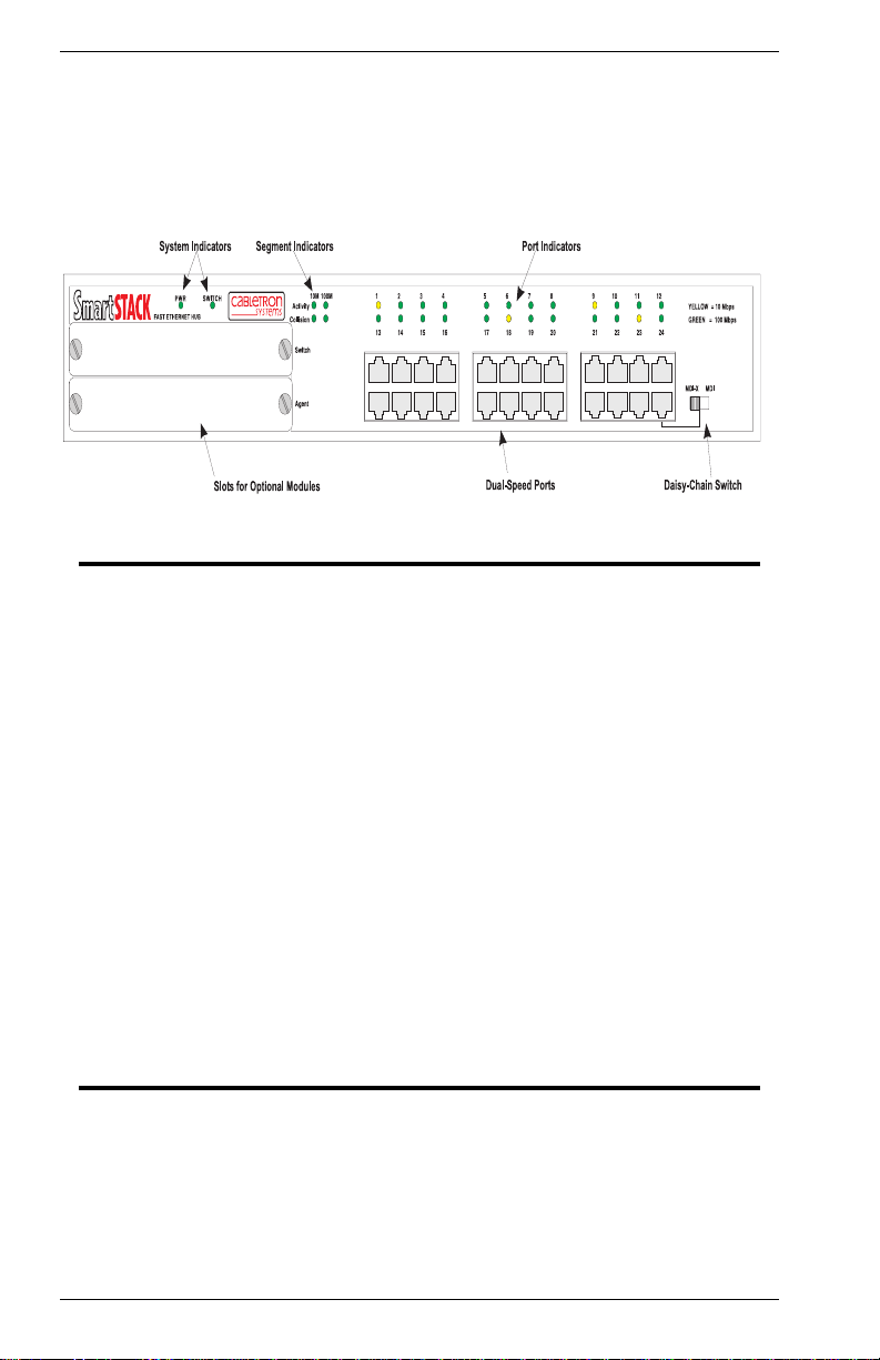
Front Panel
Figure 1-1 shows the front panel of the Cabletron ELH100-24TX.
Table 1-1 defines the ELH100-12/24TX front panel components.
Figure 1-1. ELH100-24TX Front Panel
XXXX XXXX XXXX
ELH100-24TX
Table 1-1. Front Panel Components
Name Function
PWR LED Lightssteady green toindicate power issuppliedto the
SWITCH LED Lights steady green to indicate that the Switch/Media
Segment LEDs
(10M, 100M)
Port LEDs On indicates link; off indicates no link; and flashing
10Base-T/100Base-TX
RJ-45 ports
hub. Off i ndicat es no power is supplied to the hub.
Module is active. Flashing indicates that another
module in the stackis active. (Ifthe active module fails,
you must removeit from the stack toinitialize a backup
switch/media module located in another hub in the
stack.)
Activity: Flashing indicates traffic on the segment.
Collision: Flashing indicates t hat two or more devices
attempted to transmit data at the same time. (This is a
normal situation under Ethernet CSMA/CD.)
indicates that the port has been partitioned. Yellow
indicatesa 10 Mbps connection; green indicates a 100
Mbps connection.
Copper ports using RJ-45 port connectors. These
ports are wired MDI-X, except for the last port which
includes a selection switch for MDI-X or MDI
connection.
4 Product Overview ELH100-12/24TX
Page 23
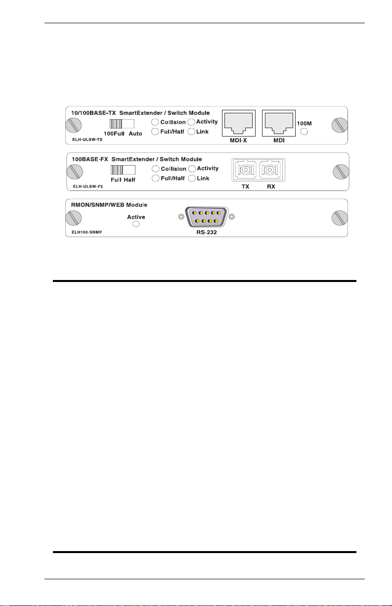
Optional Modules
Figure 1-2 shows the optional modules available for the Cabletron
ELH100-12/24TX. Table 1-2 defines the optional module components.
Figure 1-2. Optional Modules
Table 1-2. Optional Module Components
Module Components
10Base-T/100Base-TX
100Base-FX
Agent Console port: Male DB-9 connector configured as a
Ports: Copper ports using RJ-45 connectors. Use either
the MDI-X or MDI connector when attaching a device
to this module. (See 10Base-T/100Base-TX Ports on
page 24 for a detailed description of these ports.)
Mode switch: If the attached device must operate at
100 Mbps, full duplex, then set this switch to 100Full;
otherwise, set it t o Auto.
Port LEDs: See Table 1-3 for details.
Ports: Fiber ports using SC connectors for uplink. (See
100Base-FX Fiber Ports on page 25 for a detailed
description of these ports.)
Mode switch: If the attacheddevice must operate atfull
duplex, set this switch t o Full; otherwise, set it to Half.
Port LEDs: See Table 1-3 for details.
null modem connection for serial ou t-of-band
management using the console m enus, or for in-band
management when used with SLIP protocol.
Active LED: On when the Agent Module is active;
when the module is in standby mode, and flashing if
the module failed the power-on self-test.
Only two agent modules are allowed in a stack: one
active and one in standby mode.
off
9033060 Product Overview 5
Page 24

Figure 1-3 shows the Collision, Activity, Full/Half duplex, and Link LEDs
forthe switch/media modules. These LEDsare positioned to theleft of the
ports. In addition, the 10Base-T/100Base-TX module includes a 100M
LED to right of the ports to indicate speed (where On indicates that the
port is operating at 100 Mbps, and Off indicates 10 Mbps).
Figure 1-3. Port LEDs on the Switch/Media Modules
Collision
Full/Half
Activit y
Link
Table 1-3 definesthe performance of the port LEDs on the optional modules.
Table 1-3. Port LEDs for Modules Defined
Name Function
Collision Flashing: Two ormore devices attempted to transmit dataat the same
Activity Flashing: Indicates the presence of transmit and/or receive activity.
Full/Half On: Indicates the port is in full duplex mode.
Link On: Indicates a valid connection (link) on t he associated port.
100M* On: Indicates that the port is operating at 100 Mbps.
* This LED only appears on the 10Base-T/100Base-TX module.
time. (Normal situation under Ethernet CSMA/CD.)
Off: Indicates the absence of transmit or receive activity.
Off: Indicates the port is in half duplex mode.
Off: Indicates no link on the associated port.
Off: Indicates that the port is operating at 10 Mbps.
The Switch/Mediamodules do not support Spanning Tree, which is intended to prevent network
loops from forming. Thereis no loop detection. The
user is cautioned to understand and avoid configurations that can create a loop.
6 Product Overview ELH100-12/24TX
Page 25

Rear Panel
Figure 1-4 shows the ELH100-12/24TXrear panel and Table 1-4defines
the rear panel components.
Figure 1-4. ELH100-12/24TX Rear Panel
Table 1-4. Rear Panel Components
Name Function
Power Connector Provides AC power to the switch.
Redundant Power
Connector
Stack Connectors Allows you to stack up to 6 unit s to form a dual-speed
This connector is provided for a redundant power unit
(RPU) which can supply power to the hub if its primary
power supply fails. (Refer to the m anual provided with
the RPU for further details.)
network of up to 144 ports.
Feature Summaries
The following summaries describe ELH100-12/24TX features in areas
such as standards compliance, functionality, performance, and options.
Dual-Speed Architecture
The ELH100-12/24TX hub provides both 10 and 100 Mbps repeater
buses. The speed of the device connected to each port is automatically
detected by the hub, and the port attached to the appropriate bus. Up to
6 hubscan be stacked together to form a dual-speed network. An optional
switch/mediamodule canbeadded to anyhub in thestackto bridgetraffic
between the 10 Mbps and 100 Mbps repeater buses as required.
Software Download
The ELH100-12/24TX h ubs support the industry-standardTrivial File
Transfer Protocol (TFTP) for downloading agent software. All hub
softwareis storedin a 2 MB flashROM. Thedownload featureallows you
to easily install software upgrades to the Agent Module. Software can
alternatively be downloaded via the serial console port using the
XMODEM protocol. You can download to permanent flash ROM, or you
can download to temporary storage in RAM for test purposes.
9033060 Product Overview 7
Page 26

A TFTP or XMODEM software download is invoked via the console
menus. A TFTPdownload can also be invoked via SNMP or Web-based
manager.
Non-volatile Parameter Storage
All important operating parameters,such as management data and port
configurations,are storedinnon-volatileFlashmemory. These values are
retained when the hub experiences power interruptions or is powered
down for normal maintenance.
Configuration and Management Interfaces
TheELH100-12/24TXhub, or attached stack, can be managedusing any
of the following methods:
• Serial console, out-of-band or in-band
An RS-232 connection, using a DB-9 connector, is included on the
AgentModule for system management.Serial consolemanagement
can be performed out-of-band using a terminal or computer running
communications software. You can connect directly to the RS-232
port on the Agent Module, or make a connection via a modem. See
Chapter 3, ELH100-12/24TX User Interface, for information on
managingthe ELH100-12/24TX hub(or stack)via the serialconsole.
You can also make an in-band connection to the RS-232port on the
Agent Module with SLIP protocol. Using this kind of connection, you
can manage the system via any of the methods listed below.
• Telnet, in-band (over Ethernet)
The hub supports management through a Telnet connection using
the TCP/IP protocols. Telnet is performed using a terminal or
computer running communications software. See Chapter 3,
ELH100-12/24TX User Interface, for information on managing the
system via Telnet. Global user name and password protection for
changing the operating parameters of the hub is provided.
• Web-based network manager, in-band
The system can be managed over HTTP protocol with a Web
browser (Internet Explorer 3.0 or above, or Netscape Navigator 3.0
or above).Standard agent MIBs embedded in the hub provide basic
SNMP management through an embedded graphic interface.
• SNMP-based network manager, in-band
The system can also be managed using SNMP, the most common
protocol used today for network management. Standard agent MIBs
embedded in the hub provide basic SNMP management through
industry-standardSNMP applications.
Management security protection is provided based on SNMP
community names. See Chapter 6, SNMP Management, for more
information.
8 Product Overview ELH100-12/24TX
Page 27

RMON
RMON (Remote Monitoring) is a facility used to manage networks
remotelywhileprovidingmulti-vendorinteroperabilitybetweenmonitoring
devices and management stations. RMON is defined by an SNMP MIB.
This MIB is divided into nine different groups, each gathering specific
statistical information or performing a specific function. RMON-capable
devices gather network traffic data and then store them locally until
downloaded to an SNMP management station.
The ELH100-12/24TX supports four of the nine groups of RMON defined
for Ethernet networks on a per segment basis. Specifically, these are:
• Statistics:a functionthat maintains countsof networktraffic statistics
such as number of packets, broadcasts, collisions, errors, and
distribution of packet sizes.
• History: a function that collects historical statistics based on user-
definedsamplingintervals.The statisticalinformationcollectedis the
same as the Statistics group, except on a time stamped basis.
• Alarm:a function that allowsmanagerstoset alarmthresholdsbased
on traffic statistics. Alarms trigger other actions through the Event
group.
• Event: a function that operates with the Alarm group to define an
action that will be taken when an alarm condition occurs. The event
may write a log entry and/or send a trap message.
Becausethe Agent Modulemustbe attached toeither the 10or 100Mbps
stack segment, RMON can only be activated for one segment at a time.
You must therefore use an out-of-band connection to the Agent Module
to select the segment to activate for RMON. However, note that RMON
statistics and other information can only be viewed using a connection to
the on-board web agent or via other compatible SNMP management
applications.
Auto-Sensing and Auto-Negotiation
Auto-sensingis a process that permits the hub to automaticallyselect the
operational speed of its ports. When an RJ-45 port on the base unit is
connected, the hub detects and configures the port to the speed of the
network the port is connected to, either 10 Mbps or 100 Mbps. Autosensing is configurable i n the Port Configuration Menu of the console
menus or via SNMP.
The 10Base-T/100Base-TX optional modules support auto-negotiation.
The port automatically negotiates the best connection possible with the
attached device. However, if the attached device must operate at full
duplex,thenit must alsosupportauto-negotiation.Otherwise,you can set
the mode manuallyusing the mode selection switchon themodule, or via
the management agent.
The 100Base-FX module does not supportauto-negotiation.You needto
configure the duplex setting via the front panel switch.
9033060 Product Overview 9
Page 28

BootP
The Bootstrap Protocol (BootP) provides for the capability of passing
configuration information to hosts on a TCP/IP network. Using this
process, network devices do not need to be configured before they can
communicate using the TCP/IP protocol suite. The ELH100-12/24TX
uses BootP to automatically configure IP address information without
requiring access to the console menus. BootP operation is configurable
usingtheSystemConfigurationMenu of theconsolemenus,the on-board
Webagent,orviaSNMP.
LEDs
The port LEDson the hub unit providea quick and accurate displayof the
integrity of hub connections, indicating link and partition for each of the
ports.The port LEDs on the optional switch/mediamodules indicate Link,
Activity, Collision, Full/Half duplex mode, and speed (100M) for each of
the ports.
The 100M LED appears only o n the 10Base-T/
100Base-TX module.
Full Duplex Mode
Fullduplexmodeissupportedon the optionalswitch/mediamodules.This
mode of operation can double the throughput of port connections, by
disabling the collision detection portion of the Ethernet Carrier Sense
MultipleAccesswithCollisionDetection(CSMA/CD)protocol,allowingfor
two-way traffic. Full duplexis configurable usingthe Duplex parameterin
the Switch/Media Menu of the console menus or via SNMP.
Application Example
Theexplodingpopularityof theInternetand ofcorporateintranets, as well
as new, high-bandwidth desktopapplications, are driving the demand for
Fast Ethernet. The need to gradually phase in Fast Ethernet networks,
without abandoning existing 10 Mbps network segments, is driving the
need for economical dual-speednetwork solutions.
TheELH100-12/24TXhubsare idealforgraduallybuildingup thenetwork
infrastructure needed to meet the demands of today’s data intensive
applications, while retaining the use of legacy network equipment. The
hubs’ low cost, high port count, and stacking capability make them
attractive and affordable for dedicated 10/100 Mbps connectionsto the
desktop. In addition, extensivefeatures, including redundant links, port
security, and micro-segmentation of bus connections, provide the
management needed for the workgroup and local backbone.
10 Product Overview ELH100-12/24TX
Page 29
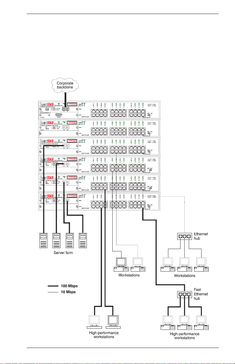
Using the ELH100-12/24TX hub in an application example for client/
server networks, users can be connected directly to the local network,
regardless of whether they are operated at either 10 or 100 Mbps. Up to
144 connections can be supported by stacking up to 6 hubs. Being a
ClassII hub, additional10Mbpsor 100 Mbpshubs can be attached to the
stack.Theoptionalmodules provide full duplexswitchedconnectionsthat
can improve workstation performance in a client/serverenvironment, or
be used to aggregate traffic on the stack to the local backbone.
Figure 1-5. Client/Server Network Application
F2
F2
F2
F2
F2
F2
9033060 ProductOverview 11
Page 30

Page 31

2. INSTALLATION
Inspecting Your Shipment
Whenyou receive the shipment ofyour hub, check the packagecontents
and make sure you have the following items:
• ELH100-12/24TX dual speed Ethernet hub
• Mounting ears and mounting screws
• Four rubber feet
• Stack cable
• Power cord
• This document
Site Requirements
Before you install the hub, make sure the site meets the following
requirements:
• Mounting
Provide a flat table, shelf surface, or an optional 19 in. (48.3 cm)
equipment rack.
Usean EIA standard equipmentrack thatis groundedand physically
secure.
• Power source
Provide a power source within six feet (1.8 m) of the installation
location. This source must provide 100 VAC to 240 VAC, and 50 Hz
to 60 Hz power,with a 50 VA minimum. Power specificationsfor the
hub are shown in Appendix A, “Technical Specifications.”
Primaryvoltage selectionwithin the above rangesis
automatic and requires no user action.
• Environmental
Install the ELH100-12/24TX hub in a dry area, with adequate air
circulation.Avoid placing the hub in directsunlight ornear other heat
sources, such as hot-air vents. For temperature and humidity
specifications,see Appendix A, “Technical Specifications.”
• Ventilation
Do not restrict airflowby covering orobstructing airinlets on theside
of the hub.
9033060 Installation 13
Page 32

Mounting the Hub or Stack on a Table or Shelf
You can mount a standalone hub (or a stack of up to six hubs) on a table
orshelf. Locate thehub (stack)in a positionthat allows accessto the front
panel RJ-45 ports, visibility of the port LEDs, and access to the power
cord. Make sure that the mounting surface can safely support the hub
(stack) and that there is adequate space around the hub (stack) for
ventilation and cooling.
1. Thehub ships withfour(4) rubber feet.Stickthe self-adhesiverubber
foot pads on each of the four concave spaces located on the bottom
of the hub. The rubber foot pads cushion the hub against shock/
vibrations and provide space between each hub for ventilation.
2. If you want to stack hubs, repeat step 1 for each hub to be stacked.
Place thefirst hub on a firmflat surface where you want to install the
stack. Stack the other hubs on top of this unit.
3. Refer to "ConnectingHubs to the Stack’s Backplane" on page 16.
14 Installation ELH100-12/24TX
Page 33

Mounting the Hub in a Rack
The hub ships with two (2) multi-position mounting ears and four (4)
mounting screws.
The mounting screws are used to attach the mounting ears to the hub. Once the ears are attached to
thehub, you will need to provideappropriatescrews
to mount the hub in a rack.
Figure 2-1 shows the orientation of the mounting ears for attaching the
ears to the hub for a rack mount application. Mount the hub with the front
panel facing forward. Do the following:
1. Mountoneof theearsto the hubusingtwo (2)ofthe suppliedscrews.
Repeat this step for the other side of the hub.
2. Slide the hub into the rack and align the holes in the rack mounting
ears with the holes in the rack rails.
3. Insert and tighten appropriate rack-mountingscrews (not provided).
4. Refer to "Connecting Hubs to the Stack’s Backplane" on page 16.
Figure 2-1. Mounting the Hub in a Rack
9033060 Installation 15
Page 34

Connecting Hubs to the Stack’s Backplane
The hub ships with a stack cable.
The hubs support a power-off bypass feature which
allows traffic to pass freely across the stack’s backplane, even if one or more of the hubs are powered
off.
Figure 2-2 shows how the stack cables are cascaded between the hubs
ina stack (rack).Toconnect up tosix hubstothe backplane, plug oneend
of the stack cable in the "Out" port of the top hub and the other end to the
"In" port of the next hub. Repeat this step for each hub in the stack (or
rack). Form a simple chain starting at the Out port on the first hub and
ending at the In port on the last hub.
Figure 2-2. Connecting Hubs to the Stack’s Backplane
16 Installation ELH100-12/24TX
Page 35

Installing an Optional Module into the Hub
Optionalmodulesareavailableformediaextensionand internalswitching
between repeater buses and management.These modules can be
installed into the modular slots on the left side of the hub. The Agent
Module must be installed in the lower slot, and all other modules in the
upper slot.
DO NOT i nstall slide-in modules with the hub powered
on.Besureyoupower off the hub before installingany
module.
To install an optional module into the hub, do the following:
1. Disconnect power to the hub.
2. Removethe blankmetalplate (ora previouslyinstalledmodule) from
the appropriate slot by removing the two screws with a flat-head
screwdriver.Aswitch/mediamodule can beinstalledin theupperslot
on the frontof thehub. AnAgent Modulecan be installedin thelower
slot on the front of the hub.
3. Before opening the package that contains the module, touchthe bag
to the hub casing to discharge any potential static electricity.
4. Remove the module from the anti-static shielded bag.
5. Holding the module level, guide it into the carrier rails on each side
and gently push it all the way into the slot, ensuring that it firmly
engages with the connector.
Figure 2-3. Installing an Optional Module into the Hub
6. If you are sure the module is properly mated with the connector,
tighten the retainer screws by hand to secure the module in the slot.
7. Connect power to the hub.
9033060 Installation 17
Page 36

Using a Switch/Media Module
The 10 and 100 Mbps repeater buses in the hub can be linked together by
installinganoptionalswitch/mediamodule in theupperslot on thefront panel.
Theswitch/mediamoduleis used whentraffic must be passedto adestination
in the other segment, when broadcast traffic is sent, or when the destination
isunknown. The switch/mediamodulepasses traffic betweenthe source and
destination segment at full duplex, using store-and-forward processing.
Multipleswitch/mediamodules may beinstalledin astack, but onlyone of the
modules will actively bridge the 10/100 Mbps repeater buses. If the active
switch/mediamodule fails, it must be removed from the hub to activate the
standby module.
Table 2-1. Optional Modules
Part Number Functions Description
ELH-ULSW-TX 10Base-T/
100Base-TX,
plus internal
switching
ELH-ULSW-F2 100Base-FX-
MM, plus internal switching
ELH100-SNMP RMON/SNMP/
Web Management
Single-port RJ-45 uplink module using MDI-X and
MDI connectors, with internal switching bet ween
the 10 and 100 Mbps repeater buses.
2-port MultiMode (MM) fiber uplink module using
SC fiber connectors, with internal switching between the 10 and 100 Mbps repeater buses.
Agent Module used to manage the hub (or attached
stack). Includes RS-232 serial port for console connection. One backup agent module can be installed in the stack.
18 Installation ELH100-12/24TX
Page 37

Connecting a Terminal to the Console Port
The console port is a serial RS-232 interface port that enables a
connection to a terminal for performing hub monitoring and configuration
functions. The terminal may be a PC or workstation running terminal
emulation s oftware, or a terminal configured as a Data Terminal
Equipment(DTE) connection.Alternatively,this port can beconnected to
an external modem to enable remote dial-in management. You can use
the out-of-band management program (described in the next chapter)
over a standard modem connection. Or, by running SLIP protocol over a
modem connection, you can use in-band management applicationssuch
as the Web agent embedded in the Agent Module or third-party SNMP
network management software.
If you connect a terminal to the console portprior to powering on thehub,
you can observe the progressand results of the power-up diagnosticsas
the hub goes through its initialization process.
The console port connector is configured as a male null modem
connection using a male DB-9 (see Table A-1 for pinouts). A standard
straight-throughwired RS-232cableis supplied with theAgentModule for
connecting to this interface. This cable is shielded to comply with
emissions regulations and requirements.
Console Port (Out-of-Band) Connections
To connect the ELH100-12/24TX console port to a terminal, do the
following:
1. Connect a VT100 compatible terminal or a PC running a terminal
emulation program to the console port (Figure 2-4). Use the nullmodem cable provided with the Agent Module, or use a null modem
connection that complies with the wiring assignmentsshown in
Appendix A.
Figure 2-4. Connecting a Terminal to the Console Port
9033060 Installation 19
Page 38

2. Connectoneend ofthe interfacecabledirectlyto theAgent Module’s
console port and tighten the retaining screws.
3. Connect the other end of the interface cable to a terminal (in some
instances, an adapter may be required to make this connection).
4. From your terminal, start the terminal emulation program.
5. Configure the terminal to the following communication settings:
VT100emulation,9600 baud, noparity, 8 databits, 1 stop bit, noflow
control, ASCII character set.
Remote Management via the Console Port
Configure the Hub Site - Connect the Agent Module’s DB-9 serial port
to the modem’s serial port using standard cabling. For most modems
using a 25-pin port,you will have to provide an RS-232 cable witha 9-pin
connector on one end and a 25-pin connection on the other end. You do
not have to set the modem at the hub’s site, because the hub will
automatically configure it to auto-answer mode.
Configure the Remote Site - At the remote site, connect the PC’s COM
port(COM 1~4)to themodem’s serialport. Set terminalemulation typeto
VT100, specify the port used by your PC (i.e., COM 1~4), then set
communicationsto 8 data bits, 1 stop bit, noparity, 9600 bps, and no flow
control.
In-Band Connections
Prior to accessingthe Agent Module via a network connection, you must
configure it with a valid IP address, subnet mask, and default gateway
using an out-of-band connection or the BOOTP protocol.
The Agent Module will automaticallyissue BOOTP requests if the IP add ress is set to "0.0.0.0". BOOTP is
disabled if a valid IP address has been set. Refer to
System Configuration Menu on page 33.
Telnet Connection - Prior to accessing the Agent Module via an in-band
Telnet connection, you must configure it with a valid IP address, subnet
mask, and default gateway using an out-of-band connection or the
BOOTP protocol. After configuring the hub’s IP parameters, you can
access the on-board configuration program from anywhere within the
attached network
.
In-BandNetworkConnection - Theon-boardconfigurationprogramcan
be accessed using Telnet from any computer attached to the network.
The hub and stack can also be managed by any computer using a web
browser (Internet Explorer 3.0 or above, or Netscape Navigator 3.0 or
above), or from a network computer using third-party network
management software.
20 Installation ELH100-12/24TX
Page 39

You can also make a remote network connection (via modems) to the
serial port on the Agent Module using SLIP protocol over TCP/IP. Using
this kind of connection, the system functions similar to a router, allowing
you to manage the hub or other attached devices using Telnet, a web
browser, or network management software.
Prior to accessing the hub via a SLIP connection, first
configure it with avalid SLIP IP address, subnet mask,
and default gateway.
The on-board program only p ro vides access to basic
configuration functions. To access the full range of
SNMP management functions, you must use SNMPbased network management software.
Agent Module
Table 2-2 provides information for the Agent Module
ELH100-12/24TX.
Table 2-2. Agent Module
Part Number Functions Description
ELH100-SNMP RMON/SNMP/
Web Management
Agent Module used to manage the hub (or attached
stack). Includes RS-232 serial port for console connection. One backup agent module can be installed in the stack.
available for the
9033060 Installation 21
Page 40

Powering the Hub
To supply power to the hub, connect the power cord to the hub and to a
groundedthree-prongwall outlet(Figure 2-5).SeeAppendixA "Technical
Specifications" on page 91 for more information regarding specific
international power cord requirements.
Figure 2-5. Connecting the Power Cord
The PWR LED lightsgreen (see Figure 1-1). If it does not, checkto make
sure that the power cable is plugged in correctly and that the power
source is good.
When power is applied, the hub conducts a series of hardware and
software tests to verify operation. If a terminal or computer is connected
to the console port, the results of the tests are displayed on the screen. If
you want to display the results of the tests after the hub has been turned
on, turn the power to the hub off then back on.
The hub performs two basic types of tests at power-up. During this time,
all the LEDs light in sequence. These tests are:
• Serial port
The serial console port test is the first test. If the hub fails, no further
tests are performed and the console displays no information.
• Memory
Memory tests on the CPU RAM are performed after the serial port
test. No results are displayed on the console.
After these tests are performed, the operational software of the hub is
loaded. A series of more extensive diagnostic tests are then conducted.
The results of the tests are displayedon the terminal.If all testspass, the
LEDsreturn tonormal operation.Whenall testsare complete, thesystem
is functional and the user interface is ready to receive commands at the
console.
22 Installation ELH100-12/24TX
Page 41

Network Cable Requirements
Copper
Table 2-3 specifiesthe cable types and length constraints for the various
copper interfaces on the ELH100-12/24TX.
Table 2-3. Copper Cable Specifications
Interface Type Cable Requirement Maximum Length
10Base-T Category 3 or 5 Unshielded Twisted
Pair (UTP)
100Base-TX Category 5 UTP 100m (328 ft.)
Fiber
Table 2-4 specifies the fiber types, bandwidth requirements, and length
constraints for the Fast Ethernet fiber interface on the fiber optic switch/
media modules.
Table 2-4. Fast Ethernet Fiber Specifications
100m (328 ft.)
Interface Type Fiber Type Fiber Diameter
100Base-FX(SC
connectors)
multi-mode 62.5 2,000m (6,560 ft.)
(microns)
Maximum Length (m)
9033060 Installation 23
Page 42

10Base-T/100Base-TX Ports
The 10Base-T/100Base-TX ports use RJ-45 connectors. Figure 2-6
shows an RJ-45 connector being inserted into a port.
Figure 2-6. Inserting an RJ-45 Connector into a Port
The ports on the base unit are wired with the MDI-X function
implemented. These ports interface to UTP cabling for
connection to
10Base-T or 100Base-TX network segments or end-stations.
connections meet the requirements of ISO 8877, specified by 10Base-T,
Section 14 of the IEEE 802.3 specification. Workstations or servers can
beconnectedto these portsusingstandardstraight-throughwiredcables.
For connections to other hubs or switches, Port 12 (24) on the ELH10012TX (ELH100-24TX) hub includes a switch for MDI or MDI-X selection.
If an MDI port is not available on the hub, a crossover
necessary (refer to
MDI/MDI-X Crossover Cable Wiring on page 94). See
cable may be
Table A-2, “10Base-T/100Base-TX Pinouts,” on page 93 for 10Base-T/
100Base-TX connector pin assignments.
The 10Base-T/100Base-TX switch/media module includes one port wired
for MDI-X and one port wired for MDI. You can not use both ports on the
module at the same time.
Table 2-5 provides information for the single port 10Base-T/
uplink moduleavailable for the ELH100-12/24TX.
Table 2-5. 10Base-T/100Base-TX Uplink Module
Part Number Functions Description
ELH-ULSW-TX 10Base-T/
100Base-TX
Single port RJ-45 uplink module using MDI-X
and MDI connectors, with internal switching
between the 10 and 100 Mbps repeater buses.
These UTP
100Base-TX
24 Installation ELH100-12/24TX
Page 43

100Base-FX Fiber Ports
The 100Base-FX Fiber port uses SC connectors. Figure 2-7 shows an
SC
fiber connector being inserted into a fiber port on the ELH100-12/24TX.
Figure 2-7. Inserting an SC Fiber Connector into a Fiber Port
The fiber uplink modules employed (Table 2-6) support multi-mode 62.5/
125mm fiber. The 100Base-FX ports use SC fiber connectors. The fiber
connectors are configured as a receive (RX) / transmit (TX) pair.
Table 2-6. Fiber Uplink Module
Part Number Functions Description
ELH-ULSW-F2 100Base-FX-MM 2-port multi-mode (MM) fiber uplink moduleus-
ingSCfiber connectors, withinternalswitching
between the 10 and 100 Mbps repeater buses.
9033060 Installation 25
Page 44

Page 45

3. ELH100-12/24TX USER INTERFACE
Overview
Access is gained to the console menus by connecting a terminal to the
console port (with a direct cable connection or over modems), or using
Telnet to access the Agent Module over the network. These menus allow
you to reconfigure the hub, as well as to monitor the status and
performance of the hub or the attached stack. The menus have a layout
similar to the sample Main Menu shown in Figure 3-1. The information is
divided into the following parts:
• Menu Name (includes access privileges)
• Selectable Items
• Screen Prompt for menu selections and entry of field parameters,
and Message Area for display of parameters or error messages.
Figure 3-1. Sample Main Menu
9033060 ELH100-12/24TX User Interface 27
Page 46

User Access
Once a direct connection to the serial port or a Telnet connection is
established, the login screen for the on-board configuration program
appears
The default user names are “admin” and “guest,” with corresponding
defaultpasswords“admin”and“guest.”TheadministratorhasRead/Write
access, which allows you to read and modify hub information. The guest
has Read Only access to the management program, which allows you to
view hub information, but not modify any operating parameters.
You should define a new administrator password,record it and put it in a
safeplace. Fromthe MainMenu, selectUserPasswords and enter a new
password for the administrator. Passwords can consist of up to 14
alphanumeric characters and are not case sensitive.
To use the console menus, do the following:
1. Use the cursor keys to highlight the desired option.
If the selected item is a submenu title, the submenu is displayed
when you press the Enter key.
2. Follow the screen prompts to specify the parameter requested.
If the selected item is a parameter, the system displays a prompt for
the entry of a new parameter value. If the value entered is invalid, a
message displays, requesting you to enter a valid value.
. You may need to press Enter a few times to display the screen.
A user isallowed three attempts to enter the correct
password; on the third failed attempt the current
connection is terminated.
Factory Defaults
Table 3-1 lists the default settings for the hub configuration parameters.
Each parameter can be changed via the console menus or Telnet.
Table 3-1. Factory Default Settings
Parameter Default Value
BootP Enable Yes
Port Enable Yes
Screen Timeout 10
Send Modem Initialization String (ATQ0V0S0=1) Yes
SNMP Public Community Name public
Terminal Baud Rate 9600
Terminal Hardware Flow Control No
28 ELH100-12/24TX User Interface ELH100-12/24TX
Page 47

Menu Hierarchy
Figure 3-2 shows the ELH100-12/24TX user interface menu hierarchy.
Figure 3-2. ELH100-12/24TX User Interface Menu Hierarchy
9033060 ELH100-12/24TX User Interface 29
Page 48

Main Menu
The Main Menuis the first screen seen after successfully logging in to the
system. Figure 3-3 shows the Main Menu and the accompanying table
describes the Main Menu
System Information ... Exit ...
Restart Hub ...
System Configuration ... TFTP Download ...
SNMP Configuration ... XMODEM Download ...
Hub Configuration ... User Password ...
Port Configuration ... Console Configuration ...
Hub Statistics ... Port Statistics ...
Display or work with system information
Use <TAB> or cursor keys to move, <ENTER> to select
Selection Description
System Information Provides system description, including system name and other
Restart Hub Performsa software reset ofthe managementagentfor all hubs
Exit Logs out of the console interface. Once you log out , you must
System Configuration Configures IP parameters, including address, subnet mask,
SNMP Configuration Conf igures communities and trap destinations.
Hub Configuration Displays hardware/firmware versions f or hub, isolates/attaches
Port Configuration Disables/enables any port;andsets communication mode to10
TFTP Download Downloads new firmware version to update the Agent Module
data.
in stack or for a selected hub by restarting the system software
and reloading certain operating parameters.
enter a user name and password before you can access the
console interface again.
gateway, SLIP IP, default bootup IP. Specifies maximum
number of Telnet sessions. Specifies the SNMP agent’s
segment.
hub’s repeater segments, and shows if an Agent Module or
switch/media module is installed. If an Agent Module is
installed, shows its bootup option, MAC address, hardware/
firmware versions, and the Baud rate of the serial port.
or 100 Mbps, or auto-sensing.
over the network.
.
Figure 3-3. Main Menu
Main Menu
=========
Configuration Screens
=====================
Statistics Screens
==================
30 ELH100-12/24TX User Interface ELH100-12/24TX
Page 49

XMODEM Download Downloads new firmware to update the Agent Module via a
console interface.
User Password Sets Administrator and Guest names and passwords used for
system access.
Console Configuration
Sets console time-out and refresh period for displayed statistics.
Hub Statistics Displays network performance for each hub in the stack.
Port Statistics Displays network performance for the selected port.
System Information Menu
Use the System Information menu to display descriptive information
aboutthehub, or forquicksystemidentification.Figure 3-4shows and the
accompanyingtable describes the System Information menu
Figure 3-4. System Information Menu
SystemInformation
==================
System Desc.: Cabletron ELH100 Dual Speed Hub
Sys. Obj. ID: 1.3.6.1.4.1.52.3.9.1.10.5
Sys. Up Time: 6213437 (0 day 17 hr 15 min 34 sec)
System Name:
.
Contact: Cabletron Inc., 0021-516-435-6475
Location:
<APPLY> <OK> <CANCEL>
Type the system name character string
Use <TAB> or cursor keys to move, <ENTER> to select,
<Ctrl-F> to move forward a character, <Ctrl-B> to move back a character
Selection Description
System Description System hardware description.
System Object ID Object identifier for the hub’s network management subsystem
as defined in MIB I I.
Sys. Up Time Time since the hub was powered on.
System Name* Name assigned to the hub system.
Contact* Contact person for the system.
Location* Specifies the area or location where the system resides.
* Maximum string len gth is 255, but the screen only displays 44 characters. You
can use the arrow keys to browse the whole string.
9033060 ELH100-12/24TX User Interface 31
Page 50

Reset
Exit
Use the Restart Hub command under the Main Menu to reset the
management agent. The reset screen includes an option to return all
configuration parameters to their factory defaults.
The hub takes approximatelytwo minutes to restart.
There is no apparent activity during this time. You
should wait until the restart has completed.
Use the Exit command under the Main Menu to log out of the user
interface and terminate communications with the hub for the current
session. After this command is entered, system logout occurs
automatically.
32 ELH100-12/24TX User Interface ELH100-12/24TX
Page 51

System Configuration Menu
Use the System Configuration menu to configure the Agent Module’s
Internet Protocol (IP) parameters, define the maximumnumber of Telnet
sessions allowed, and specify to which segment (10 Mbps or 100 Mbps)
the management agent is attached. Figure 3-5 shows and the
accompanyingtable describes the System Configuration Menu.
Figure 3-5. System Configuration Menu
System Configuration
===================
Parameter Current Setting New Setting
------------ ----------- -----------
IP Address: 210.68.150.225 210.68.150.225
IP Subnet Mask: 255.255.255.0 255.255.255.0
IP Gateway: 0.0.0.0 0.0.0.0
SLIP IP: 0.0.0.0 0.0.0.0
SLIP Subnet Mask: 0.0.0.0 0.0.0.0
SLIP Gateway: 0.0.0.0 0.0.0.0
----------------------------------------
Maximum number of allowed Telnet sessions (0 - 2) : 2
Agent Ethernet Port Attached to: 100 Mb/s
<APPLY> <OK> <CANCEL>
Type the new IP address
Use <TAB> or cursor keys to move, <SPACE>to toggle, <ENTER> to select,
<Ctrl-F> to move forward a character, <Ctrl-B> to move back a character
Selection Description
IP Address IP address of the agent y ou are managing. Valid IP
addresses consist of fournumbers (0 to 255)separated
by periods. Anything outside of this format will not be
accepted by the configuration program. If the IP
address is set to 0.0.0 .0 (the default), the SNMP agent
will automatically issue BOOTP requests to a BOOTP
server to learn its IP address. BOOTP requests will be
disabled by configuring the agent with a valid IP
address.
Subnet Mask Subnet mask of the management agent you have
selected. This mask identifies the host address bits
usedfor routing to specific subnets.(Thedefaultsubnet
mask is 0.0.0.0.)
Default Gateway Gateway used to pass trap messages from the
management agent to the network management
station. Note that t he gateway must be defined if the
management station is located in a different IP
segment. (The default gateway is 0.0.0.0.)
9033060 ELH100-12/24TX User Interface 33
Page 52

SLIP IP IPaddress of the Agent Module used when accessing
the configuration program via an out-of-band SLIP
connection to the serial port.
The hub does not allow the SLIP IP address to be the
same as the IP address.
SLIP Subnet Mask Subnetmask for the SLI P IPaddressused by the Agent
Module.
SLIP Gateway SLIP gateway IP address used to pass tr affic to the
network management station. Note that the gateway
must be def ined if the management station islocated in
a different IP segment.
Max # of allowed
Telnet sessions
The maximum number of Telnet sessions allowed to
simultaneously access the Agent Module.
Note: The maximum num ber of management sessions
(not necessarily Telnet sessions) is 2.
Agent Ethernet Port
Attached to
The network segment (10 Mb/s or 100 Mb/s) to which
the Agent Module is attac hed.
34 ELH100-12/24TX User Interface ELH100-12/24TX
Page 53

SNMP Configuration Menu
Use the SNMP Configuration Menu to display and modify parametersfor
the Simple Network Management Protocol (SNMP). The Agent Module
monitors the hardware status of the hub (or connected stack), as well as
the traffic passing through the ports. A Network Management Station
(NMS)canaccessthisinformationusingthird-partynetworkmanagement
software. Access rights to the management agent are controlled by
community strings. To communicate with the management agent, the
NMS must first submit a valid community string for authentication.The
options for configuring community strings and related trap functions are
described in Figure 3-6, Figure 3-7, and Figure 3-8 and their
accompanyingtables
Figure 3-6. SNMP Configuration Menu
.
SNMP Configuration
==================
Transmit Authentication Failure Traps: YES
SNMP Communities ...
SNMP Trap Destinations ...
<APPLY> <OK> <CANCEL>
Press <ENTER> to go to the SNMP Communities Screen
Use <TAB> or cursor keys to move, <SPACE> to toggle, <ENTER> to select
Selection Description
Transmit
AuthenticationFailure
Traps
SNMP Communities Assigns SNMP access based on specified community
SNMP Trap
Destinations
9033060 ELH100-12/24TX User Interface 35
Issue a trap message whenever authentication of an
SNMP request fails. The default i s to issue traps to
specified IP trap managers.
strings.
Specifies management stations that will receive
authentication failure messages or other trap
messages from the hub.
Page 54

SNMP Communities
Figure 3-7. SNMP Communities
SNMP Communities
================
Community Name Access Status
------------ --------- -------
1. public READ/WRITE Enabled
2.
3.
4.
5.
<APPLY> <OK> <CANCEL>
Type a community name, 20 characters or less
Use <TAB> or cursor keys to move, <SPACE> to toggle, <ENTER> to select,
<Ctrl-F> to move forward a character, <Ctrl-B> to move back a character
Selection Description
Community Name The community name for read only SNMP access to
Access Management access is Read Only or Read/Write.
Status Indicates operational status of the communit y as
the device (1-10 character range; the def ault name is:
“public”).
Enabled or Disabled.
36 ELH100-12/24TX User Interface ELH100-12/24TX
Page 55

SNMP Trap Destinations
Figure 3-8. SNMP Trap Destinations
SNMP Trap Destinations
======================
IP Address Community Name Status
-------- ----------- -----
1.
2.
3.
4.
5.
6.
7.
8.
9.
10.
<APPLY> <OK> <CANCEL>
Type an IP address for a trap destination
Use <TAB> or cursor keys to move, <SPACE> to toggle, <ENTER> to select,
<Ctrl-F> to move forward a character, <Ctrl-B> to move back a character
Selection Description
IP Address The IP address of the trap destination where SNMP
Community Name The SNMP community name to use for traps forwarded
Status Indicates status of entry as Enabled or Disabled.
trap messages are forwarded.
to the trap destination.
9033060 ELH100-12/24TX User Interface 37
Page 56

Hub Configuration Menus
Use the Hub Configuration menu to configure any hub in the stack. This
menuis used toconfigure theselected hub,as well as the AgentModule.
Use the following menu to view a basic description of all the hubs in the
stack, including hardware and firmware version numbers, or to open a
more detailed configuration screen for a specific hub. The information
providedby thesescreensisdescribedin Figure 3-9 andFigure 3-10,and
the accompanying tables.
Figure 3-9. Hub Selection Menu
Hub Configuration: Hub Selection Menu
=====================================
Hub Hardware POST SYSTEM Num SNMP Switch/Media Detailed
ID ID F/W Ver F/W Ver Ports Agent Module Screen
-- ------- ------ ------ ---- ---- --------- --------------
1 110000001CC8 1.00 1.00 12 Active ELH-ULSW-TX <DISPLAY DETAILS>
<PREV_SCREEN>
Press <ENTER> to go to a more detailed screen for this hub
Use <TAB> or cursor keys to move, <ENTER> to select
Selection Description
Hub ID Hub ident ifier in stack. (Up to 6 hubs may be connected via
Hardware ID Hardware version number of the repeater board.
Post Firmware Version Ve rsion n umber of the repeater firmware in permanent
System Firmware Version Version number of the repeater firmware in temporary
Number of Ports Indicates whether this device has 12 or 24 repeater ports.
SNMP Agent Indicates whether an Agent Module is installed in this hub.
Switch/Media Module Indicates which switch/media module is installed in this hub.
Detailed Screen Highlight “Display Details” and p ress <Enter> to access the
38 ELH100-12/24TX User Interface ELH100-12/24TX
the stack cable.)
memory.
memory.
configuration parameters for the hub.
Page 57

Figure 3-10. Hub Configuration Menu
Hub Configuration
Hub ID: 1 Model: ELH100-12TX
Hardware ID: 11-00-00-00-1C-C8 Number of Ports: 12
10M backplane: Isolated 100M backplane: Isolated
Status: Active H/W Ver: 0
POST Ver: 1.00 MAC Address: 00-00-1D-3F-2A-E1
System Ver: 1.00
Serial Port Baud Rate: 9600 Send Initialization String: NO
Serial Port Initialization String:ATQ0V0S0=1
Status: Not present
<APPLY> <OK> <CANCEL>
Use <TAB> or cursor keys to move, <SPACE> to toggle, <ENTER> to select,
<Ctrl-F> to move forward a character, <Ctrl-B> to move back a character
Selection Description
Hub Configuration
Hub ID Hub identifier in stack.
Hardware ID Serial number of this hub.
10M Backplane Attaches/isolates hub’s 10 Mbps repeater bus from the
Model Themodel number of this hub.
# of Ports Indicates whether this device has 12 or 24 repeater ports.
100M Backplane Attaches/isolates hub’s 100 Mbps repeater bus from the
SNMP Agent
Status Indicates if an Agent Module is installed and active.
POST Version Version number of the Agent Module’s Power-on Self-test.
System Version System firmw are version.
Serial Port Baud Rate Rate at which data is sent between the Agent Module’s
Serial Port
Initialization String
H/W Version Hardware version number of the Agent Module.
MAC Address Physical address of the Agent Module.
=================
SNMP Agent
==========
Switch/Media Module
===================
Isolate or attach the 10 Mb/s segment
stack’s data channel.
stack’s data channel.
serial port and the connected device. The suppor ted baud
rate is 9600 bps.
The modem initialization string sent from the serial port to
the attached device.
9033060 ELH100-12/24TX User Interface 39
Page 58

Serial Initialization
String
Yes, to send the i nitialization string to an attached modem.
No, if there i s a direct connection from the serial port to a
PC.
Switch Module
Status Indicates if a switch/media module is installed.
40 ELH100-12/24TX User Interface ELH100-12/24TX
Page 59

Port Configuration Menu
Select Administrative Status Control from the Port Configuration screen,
then select the port group to configure, either “1 thru 12,” “13 thru 24,” or
“Switch/Media Module” (if installed). The following screens show the
configuration options.
Port Administrative Status Control Menu
Figure 3-11. Port Administrative Status Control Menu
Port Administrative Status Control (1 - 12)
===========================================
Hub ID: 1 Model: ELH100-12TX
Port Admin State Link State Auto Partitioned Mode Speed (Mb/s)
--- -------- ------- ----------- ---- -----------
1 Enabled No Link No Auto
2 Enabled No Link No Auto
3 Enabled No Link No Auto
4 Enabled No Link No Auto
5 Enabled No Link No Auto
6 Enabled No Link No Auto
7 Enabled No Link No Auto
8 Enabled No Link No Auto
9 Enabled No Link No Auto
10 Enabled NoLink No Auto
11 Enabled NoLink No Auto
12 Enabled Link No Auto 100
<APPLY> <OK> <CANCEL> <PREV_SCREEN> <NEXT_SCREEN>
Use <TAB> or cursor keys to move, <SPACE> to toggle, <ENTER> to select
Use the space bar to toggle states
Selection Description
Admin State Allows you to disable a port due to abnormal behavior such
as excessive collisions, and re-enable it after the problem
has been resolved. You may also disable a port for security
reasons.
Link State Indicates if the por t has a valid connection to an external
device.
Auto Partitioned I ndicates if the port is partitioned.
Mode Sets the transmission speed to 10 Mbps, 100 Mbps or auto-
detection.
Speed Indicates the transmission speed currently used by this port.
9033060 ELH100-12/24TX User Interface 41
Page 60

Module Port Configuration Menu
The switch/media m odule configuration menu is accessible only if a
module is installed in the hub’s upper slot. The switch/media modules
have two internal ports that are connected to the hub’s internal repeater
segments. The configuration screen and options are displayed below.
Figure 3-12. Switch/Media Module Port Administrative Status Control Menu
Port Administrative Status Switch/Media Module
==============================================
Hub ID: 1
Model: ELH100-12TX
Module Type:TX 10/100 Switch/Media Module
Port Admin State Link State Duplex Speed (Mb/s)
--- -------- ------- ----- ---------
1 Int: Enabled Link Half 100
2 Ext: Enabled Link Half 10
3 Ext: Enabled Link Full 100
<APPLY> <OK> <CANCEL>
Use the space bar to toggle between enabled and disabled states
Use <TAB> or cursor keys to move, <SPACE> to toggle, <ENTER> to select
Selection Description
Module Type The type of module installed in the hub.
Port Port identifier for the module. Ports 1 and 2 link internally to
the hubs 100 Mbps and 10 Mbps repeater segments. Port 3
is the external port on the module’s front panel.
Admin State The module’s internal ports can be disabled to isolate the
module from the hub. You may wish to do t his if the
module’s external connection is exhibiting abnormal
behavior or for security reasons.
Link State Indicates if the port has a valid connection.
Duplex The communication mode currently used by the port, either
half duplex or full duplex.
Speed Indicates t he transmission speed currently us ed by the port.
42 ELH100-12/24TX User Interface ELH100-12/24TX
Page 61

Backup Port Control Menu
Select Backup Port Control from the Port Configuration screen to define
up to 15 master/slaveport pairs. If the connection to the masterport fails,
the slave port will automatically take over. For greater reliability, primary
and secondary ports should be located on different hubs. The following
screen and table show how to specify and activate port backup pairs.
Figure 3-13. Backup Port Control Menu
Index Primary Port Secondary Port Status Active Port
---- --------- ----------- ----- --------
1 Hub: -- Port: -- Hub: -- Port: -- -------- --------2 Hub: -- Port: -- Hub: -- Port: -- -------- --------3 Hub: -- Port: -- Hub: -- Port: -- -------- --------4 Hub: -- Port: -- Hub: -- Port: -- -------- --------5 Hub: -- Port: -- Hub: -- Port: -- -------- --------6 Hub: -- Port: -- Hub: -- Port: -- -------- --------7 Hub: -- Port: -- Hub: -- Port: -- -------- --------8 Hub: -- Port: -- Hub: -- Port: -- -------- ---------
9 Hub: -- Port: -- Hub: -- Port: -- -------- --------10 Hub: -- Port: -- Hub: -- Port: -- -------- --------11 Hub: -- Port: -- Hub: -- Port: -- -------- --------12 Hub: -- Port: -- Hub: -- Port: -- -------- --------13 Hub: -- Port: -- Hub: -- Port: -- -------- --------14 Hub: -- Port: -- Hub: -- Port: -- -------- --------15 Hub: -- Port: -- Hub: -- Port: -- -------- ---------
Use <TAB> or cursor keys to move, <SPACE> to toggle, <ENTER> to select
Backup Port Control
<APPLY> <OK> <CANCEL>
Type the hub ID for the primary port
Field Description
Index Identifier for up to 15 backup port pairs.
Primary Port Pair member serving as the primary link.
Hub Hub ID for the master port.
Port Port identifier for the master port.
Secondary Port Pair member serving as the backup link.
Hub Hub ID for the slave port.
Port Port identifier for the slave port.
Status Each backup pair can be set to Active or Inactive.
Active Port Indicates if the primary or secondary port is handling the link.
9033060 ELH100-12/24TX User Interface 43
Page 62

TFTP Download Menu
Use the TFTP Download menu to load software updates into the hub over
the network. The download file should be anELH100-12/24TX binary file
from Cabletron; otherwise, the agent module will not accept it. The
success of the download operation depends on the accessibility of the
TFTP server and the quality ofthe network connection. Afterdownloading
new software, the agent module will automatically restart itself.
Parametersshown on this screen are indicated inthe followingfigure and
table.
Figure 3-14. TFTP Download Menu
Download Server IP: 10.1.4.45
Download Mode: Upgrade DRAM and reboot
Filename: cbt0209b.bin
<APPLY> <OK> <CANCEL>
Enter the server's IP address
TFTP Download
=============
<Start TFTP Download>
Use <TAB> or cursor keys to move, <SPACE> to toggle, <ENTER> to select
Selection Description
Download Server IP IP address of a TFTP server.
Download Mode You can download to permanent flash ROM or temporary
Filename The ELH100-12/24TX binary file to download.
Start TFTP Download Issues request to TFTP server to download the specified file.
44 ELH100-12/24TX User Interface ELH100-12/24TX
storage in RAM (for test purposes). However, if you
download to temporary memory, this firmware will be lost
upon power off.
After the TFTP download is completed, the hub
takes approximately two minutes to restart. There is
no apparent activity during this time. You should
wait until the restart has co mpleted .
Page 63

XMODEM Download Menu
Usethe Xmodem Downloadcommandtoupdateavailablesoftware inthe
hub via an out-of-bandconnection to the serial port on the Agent Module.
The download file should be an ELH100-12/24TX binary file from
Cabletron; otherwise, the agent module will not accept it. This command
specifiesdirect downloadfrom an attached device via theserial port.You
may download using any terminal emulation program that can transmit
binary files using the XModem protocol. The parameters shown in this
screen are indicated in the following figure and table.
Figure 3-15. XMODEM Download Menu
XMODEM Download
===============
Download Mode: Upgrade DRAM and reboot
<Start XMODEM Do wnload>
Use the space key to select DRAM or FLASH download
Use <TAB> or cursor keys to move, <SPACE> to toggle, <ENTER> to select
<CANCEL>
Selection Description
Download Mode You can download to permanent flash ROM or temporary
Start Xmodem
Download
storage in RAM (for test purposes). However, if you
download to temporary memory, this firmware will be lost
upon power off.
Waits to receive a file sent from the attached PC running the
terminal emulation program.
To start the download process, use the XModem protocol and select the
ELH100-12/24TXbinary file.Start sendingthe file from your computerby
usingthe “send”or “upload”file facilityof the terminal emulationprogram.
Theterminal emulationprogram will displaythe progressof thedownload
process.Afterdownloading the newsoftware, the agentwill automatically
restart itself.
9033060 ELH100-12/24TX User Interface 45
Page 64

User Password Menu
The User Password menu is used to display or modify user names and
passwords for the on-board configuration program. There are two user
types, Administratorand Guest. Only the Administrator has write access
for parameters governing the SNMP agent. You should therefore assign
a user name and password to the Administrator as soon as possible,and
storeitinasafeplace.
Passwords can consist of up to 14 alphanumeric characters and are not
casesensitive.The configurationprogram willallow auserthree attempts
at entering a password before locking the user out by terminating the
current connection. If for some reason your password is lost, or you can
not gain access to the system configuration program, contact your
Cabletron distributor for a ssistance.
Figure 3-16. User Password Menu
Display/Change User Names and Passwords
=======================================
User Type User Name Password Password Verify
------- -------- -------- -----------
Administrator: admin ************** **************
Guest: guest ************** **************
<APPLY> <OK> <CANCEL>
Enter a user name, 1 to 14 characters
Use <TAB> or cursor keys to move, <ENTER> to select,
<Ctrl-F> to move forward a character, <Ctrl-B> to move back a character
Selection Default Descri ptio n
Administrator name: admin
password: admin
Guest name: guest
password: guest
46 ELH100-12/24TX User Interface ELH100-12/24TX
Administrator has access privilege of Read/Write
for all screens.
Guest has access privilege of Read O nly fo r all
screens.
Page 65

Console Configuration Menu
The Console Configurationmenu is used to configure the console
connectedto thehub’s serial port. The consoleparameters are described
in the following figure and table.
Figure 3-17. Console Configuration Menu
Console Configuration
=====================
Automatic Logout Status: ON
Automatic Logout Delay Time: 10 Minutes
Auto-Refresh Period: 30 Seconds
<APPLY> <OK> <CANCEL>
Use the space bar to toggle automatic logout
Use <TAB> or cursor keys to move, <SPACE> to toggle, <ENTER> to select
Selection Description
Automatic Logout
Status
Automatic Logout
Delay Time
Auto-Refresh Period Specifies the interval at which statistics are read from the
9033060 ELH100-12/24TX User Interface 47
Enables/disables the logout function.
If no input is received from the attached device after this
interval (in minutes), the current session is closed.
Range: 0 - 99 m in utes. Default is 10 minutes.
hub.
Options: 30, 60, 120, 180, 300 seconds. Default is 30
seconds.
Page 66

Hub Statistics Menu
The Hub Statistics screens display statistics for the 10 and 100 Mbps
stack segments. These values can be used to indicate the approximate
loading for each segment. You can use the Hub Statistics Overview
screen to display key statisticsfor all hubs in a stack or detailed statistics
for each individual hub. The Hub Statistics screens are shown in
Figure 3-18 and Figure 3-19, and described in the accompanying tables.
Figure 3-18. Hub Statistics Overview Screen
Hub Statistics Overview
=======================
10Mb/s Segments
Hub Frames Bytes Collisions CRC Errors Tot.Errors Reset Details
--- -------- ------- ------- ------- ------- ------- ------
1 892 121329 0 0 0 <RESET1> <DETAIL>
100Mb/sSegments
Hub Frames Bytes Collisions CRCErrors Tot.Errors
--- ------- -------- ------ -------- -------
1 736685 112506135 425 6 620
<REFRESH STATISTICS> <AUTO-REFRESH STATISTICS> <PREVIOUS SCREEN>
Press <ENTER> to reset both 10 and 100 Mbit statistics counters for this hub
Use <TAB> or cursor keys to move, <ENTER> to select
Field Descripti o n
Hub Hub identifier within the stack.
Frames Number of frames passing through this hub.
Bytes Number of bytes passing through this hub.
Collisions Number of simultaneous node transmissions detected by this hub.
CRC Errors Number of Ethernet Cyclic Redundancy Check errors detected by
this hub.
Total Errors Total number of errors, including FCS, alignment, Frames Too
Long, Short Events, Late Events, Jabber, and Data Rate
Mismatches detected on this device.
Reset Resets the statistics counters for the hub.
Details Highlight “Detail” and press<Enter> to display thedetailed statistics
screen for the hub.
Refresh Statistics Refresh the displayed statistics.
Auto-Refresh
Refresh statistics at the interval specified in Console Configuration.
Statistics
48 ELH100-12/24TX User Interface ELH100-12/24TX
Page 67

Figure 3-19. Detailed Hub Statistics Screen
Hub 1 Statistics
Statistic 10 Mb/s Segment 100 Mb/s Segment
------------- -------------- --------------
Readable Frames 433 763985
Readable Octets 86057 116973315
CRC Errors 0 6
Alignment Errors 0 1
Frames Too Long 0 0
Short Events 0 612
Runts 0 3
Collisions 2 425
Late Events 0 1
Data Rate Mismatch 0 0
Auto Partitions 0 1
Total Errors 0 620
<REFRESH STATISTICS> <AUTO-REFRESH STATISTICS> <RESET HUB STATISTICS>
<OVERVIEW SCREEN> <PREVIOUS HUB> <NEXT HUB>
Press <ENTER> to refresh this hub's statistics screen
Use <TAB> or cursor keys to move, <ENTER> to select
Field Descripti o n
Readable Frames Number of good frames passing through the hub.
Readable Octets Number of good octets passing through the hub.
CRC Errors Number of CRC errors detected by the hub.
Alignment Errors The number of mis-sy nchronized data packets detected by the hub.
Frames Too Long Number of times frame length has exceeded the maximum
allowable size (that is, 1518 byt es).
Short Events Number of short fragments.
Runts Number of fragments (that were too long to qualify as short events).
Collisions Number of simultaneous node transmissions detected by the hub.
Late Events
Data Rate
Mismatch
Number of frames where a collision occurred late in the transmission.
Number of f rames for which the data rate does not match the local
frequency.
Auto Partitions Number of times the hub has automatically partitioned ports due to
jabber.
Total Errors Total number of errors, including FCS, Alignment, Frames Too
Long, Short Events, Late Events, Jabber, and Data Rate
Mismatches detected on the hub.
Refresh Statistics Refreshes the displayed statistics.
Auto-Refresh
Statistics
Reset Hub
Refreshes statistics at the interval specified in Console
Configuration.
Resets the statistics counter for all items to zero.
Statistics
=================
9033060 ELH100-12/24TX User Interface 49
Page 68

Port Statistics Menu
Use the Port Statistics screen to display key statistics for each port.
Overall statistics on the traffic passing through each port are displayed.
This information can be used to identify potential problems with the hub
(such as a faulty port).
Selectthe requiredportfrom thePort Statistics: PortSelectionMenu. The
PortStatisticsScreenisshowninFigure3-20anddescribedinthe
accompanyingtable
Readable Frames: 805490 Collisions: 425
Readable Octets: 123515227 Late Events: 1
CRC Errors: 6 Data Rate Mismatches: 0
AlignmentErrors: 1 Auto Partitions: 1
Frames Too Long: 0 Total Errors: 620
Short Events: 612 LSA Changes: 672366
Runts: 3 Last Source Address:00-00-E8-42-72-E4
<REFRESH STATISTICS> <AUTO-REFRESH STATISTICS> <RESET COUNTERS>
.
Figure 3-20. Port Statistics Screen
Hub 1 Port 12 Statistics
========================
<PORT SELECTION SCREEN> <PREVIOUS PORT> <NEXT PORT>
Press <ENTER> to refresh this port's statistics screen
Use <TAB> or cursor keys to move, <ENTER> to select
Field Descripti o n
Readable Frames Number of good frames received by the port.
Readable Octets Number of good octets received by the port.
CRC Errors Number of CRC errors.
Alignment Errors For 1 0 Mbps por ts, the counter records alignment errors (mis-
synchronized data packets). For 100 Mbps ports, the counter
records the sum of alignment errors and code errors (frames
received with rxerror signal).
Frames Too Long Number of times frame length has exceeded the maximum
allowable size (that is, 1518 byt es).
Short Events Number of short fragments.
Runts Number of fragments (that were too long to qualify as short events).
Collisions
Late Events
Data Rate
Mismatches
50 ELH100-12/24TX User Interface ELH100-12/24TX
Number of simultaneous node transmissions detected by this device.
Number of frames where a collision occurred late in the transmission.
Number of f rames for which the data rate does not match the local
frequency.
Page 69

Auto Partitions Number of times this port has been automatically partitioned due to
jabber.
Total Errors Total number of errors, including FCS, Alignment, Frames Too
Long, Short Events, Late Events, Jabber, and Data Rate
Mismatches detected on this device.
LSA Changes Number of times the source address has changed.
Last Source Addr. Last source address.
Refresh Statistics Refreshes the displayed statistics.
Auto-Refresh
Statistics
Refreshes statistics at the interval specified in Console
Configuration.
Reset Counters Resets the statistics counter for all items to zero.
9033060 ELH100-12/24TX User Interface 51
Page 70

Page 71

4. CONFIGURING & MONITORING T HE HUB
Common Tasks
The hub console menus allow you to modify default hub settings and
configure the hub for network management.They also allow you to
monitor hub performance and status. See Chapter 3, ELH100-12/24TX
User Interface on page 27, for an overview of the menu hierarchy and a
description of all menus. The following sections describe common tasks
in setting up and operating the ELH100-12/24TX hub using the console
menus.
To begin, set operating parameters and make sure the network
connections are correct by performing these tasks:
• Setting password protection for the hub to prevent unauthorized
access to console menus
• Assigning an IP address for the hub if you plan to manage the hub
using SNMP, or if you use Telnet to access the hub
• Checking network configuration status and verifying that network
connections are correct
After the hub is installed and operating, you may want to perform any of
the following tasks:
• Connecting via Telnet for in-band access to the console menus
• Setting SNMP parameters for management access
• Viewing hub statistics to monitorand evaluate hub performance and
traffic patterns on the network
• Downloading a software upgrade
• Configuring port operation (enable/disable or set port speed)
• Setting a default gateway
• Configuring BootP
Setting Password Protection
The ELH100-12/24TXhub is factory-configured with access rights to the
console menus set to READ/WRITE for the administrator, and READONLY for all others. These settings allow anyone who knows the hub’s
defaultuser nameand passwordto usethe console menus to modify any
operational parameter. To protect the configuration of the hub from
unauthorized modification, you can change the password to the console
menus.
9033060 Configuring & Monitoring the Hub 53
Page 72

To enter a password, do the following:
1. Select Password from the System Configuration Menu and press
[Enter].
2. Enter a password containing 1 to 14 alphanumeric characters.
The password is not case sensitive. For verification, you are asked to
enter your password again. If both entries agree, the new password is
stored.
If you forget your password, contact your Cabletron System Support
Representative.
You are automatically logged out from the console menus
due to inactivity based on the Automatic Logout Delay Time
setting in the Console Configuration Menu.
Assigning an IP Address
To assign an IP address to the hub, do the following:
1. Select System Configuration Menu from the Main menu.
2. Select New Setting for IP address from the menu and enter the IP
address. Select <APPLY>.
The IP address is now programmed. If necessary, select Subnet Mask
from the menu and enter the appropriate mask.
Checking Network Configuration Status
To check connection status for the network, do the following:
1. Select Port Configuration Menu from the Main Menu.
If a network cable is properly connected to a port, the Link Status for
theportreads LINK. Ifno cable is connectedtothe port, orifthe cable
or port is faulty, the Link Status for the port reads NO LINK.
2. If you see NO LINK status for a connected port, plug the cable into
another port on the hub or try another cable.
54 Configuring & Monitoring the Hub ELH100-12/24TX
Page 73

Connecting via Telnet
You can connect to the ELH100-12/24TX hub from a remote location
using the Telnet application. This application allows you to establish inband access to the console menus.
To connect to the ELH100-12/24TX hub via Telnet, do the following:
1. Assign an IP address using the System Configuration Menu.
2. Login tothe ELH100-12/24TX hub viaTelnet using theconfiguredIP
address.
Setting SNMP Management Access
Access to the ELH100-12/24TX hub through SNMP is controlled by
community names. The community names set for the hub must match
those used by the SNMP management station for successful
communicationtooccur.Youcanassignuptofivecommunitynamesto
the hub using READ/WRITE or READ ONLY access. The default
community name is “public,” and provides read/write access to the hub.
The ELH100-12/24TX hub can send SNMP messages, called traps, to
SNMP management stations when an important event occurs with the
hub. The hub allows up to 10 destinationsto be configured for these trap
messages to be sent.
To configure SNMP access for the hub, do the following:
1. Select SNMP Configuration Menu from the Main Menu.
2. Select SNMP Communities from the SNMP Configuration Menu.
3. Specify a Community Name (you are permitted to enter from one to
10 characters), select the desired read/write access community
name, and set Status to Enabled.
4. Selectone or more Trap Destinationentriesfrom themenu, enter the
appropriate IP addresses, and set Status to Enabled.
6. Foreach trapdestinationentered, a correspondingcommunity name
should be entered. (This community name must be defined in the
SNMP Communities Menu.)
9033060 Configuring & Monitoring the Hub 55
Page 74

Viewing Hub Statistics
To view hub statistics, do the following:
1. Select Hub Statistics from the Main Menu.
The screenlists the main statisticalcounts for both segmentson the
hub simultaneously.
2. Select <DETAIL> from the Hub Statistics Overview screen.
The screen lists a summary of sum total statistics for all ports on the
hub.
3. Select Port Statistics from the Main Menu.
4. Enter the Hub ID and Port ID. Select <OK>.
The screen lists expanded port-level statistics for an individual port.
5. On any of the statistics screens, select <RESET COUNTERS> to
clear (zero) the displayed statistical counts and <REFRESH
STATISTICS> to refresh (update) the displayed statistical counts.
Downloading a Software Upgrade
You can upgrade the operational software in the ELH100-12/24TX hub
without physically opening the hub or being in the same location. The
software storage sector in the flash memory of the hub is
reprogrammable, allowing you to easily download software feature
enhancements and problem fixes to the hub from a local or remote
location.
Software can be downloaded to the hub in two ways:
• Via the serial port. This procedure is an out-of-band operation that
copiesthe software throughthe serial port to the hub.This operation
takes approximately 40 minutes and requires minimal configuration.
• Via TFTP download.This procedure uses a TFTP server connected
to the network and downloads the software using the TFTP protocol.
A TFTP download is much faster than a serial download, requiring
onlya matterof minutes,and can be used to upgrade an ELH100-12/
24TX hub that is not physically proximate. The disadvantage is that
this method requires a TFTP server and additional setup.
Downloading Via the Serial Port
A serial downloadis the easiest methodto upgradethe ELH100-12/24TX
hub software, requiringthe least amount of equipment and configuration.
To download hub software via the serial port, do the following:
1. Select XMODEM Download from the Main Menu.
2. Select “Upgrade FLASH and reboot.”
3. Select <Start XMODEM Download>.
56 Configuring & Monitoring the Hub ELH100-12/24TX
Page 75

4. When the system prompts, confirm that you want to proceed.
The following message prompt displays:
Receiving image...
5. Send the file using the XMODEM protocol from your computer
application (the procedure varies depending upon the application
used).
When the XMODEM procedure finishes,a message appearsstating
that the system is initializing.The login prompt displays after the system initializes. If the loginprompt does not display, youmay need to
press the Enter key several times.
Downloading Via TFTP
To perform a TFTP download, you must first configure the ELH100-12/
24TX hub. This consists of programming the hub with an IP address, if
this has not already been done, and entering the IP address of the TFTP
server and the name of the upgrade file. To program the hub IP address,
go to the TFTP Download Menu which is accessiblefrom the Main Menu
screen.
To download hub software via TFTP, do the following:
1. Enter the Download Server IP address.
2. Set the Download Mode to “Upgrade FLASH and reboot.”
3. Enter the filename to be downloaded from the TFTP server.
Depending on the system you use as a TFTP server, you may need
to include the directory name with the filename.
4. If necessary, configure the address of an IP gateway to reach the
server from the hub using the IP Gateway field on the System
Configuration Menu.
5. Configure the TFTP server by copying the download file to the
appropriate directory and starting the server.
6. Select <Start TFTP Download> and press [Enter].
To verify that the TFTP download has been successfully completed,
note the software version level displayed on the Hub Configuration
screen accessible from the Main Menu. This number should match
the version number of the downloaded file.
9033060 Configuring & Monitoring the Hub 57
Page 76

Configuring Port Operation
You can configure 10/100 ports on the base unit for operational
parameters such as enabled/disabled, and port speed or auto-sensing.
To configure port operation, do the following:
1. Select Port Configuration from the Main Menu.
2. Select Administrative Status Control from the Port Configuration
menu.
3. Select Port Group 1-12, 13-24 or Switch/Media Module.
4. Highlight any port, and select “Enabled” or “Disabled” in the Admin
State field to toggle between enabling and disabling the port(s).
5. Select “Force 10,” “Force 100” or “Auto” under the Mode field to set
the port speed to 10 Mbps, 100 Mbps or auto-detection.
The console interface can only enable/disable the
ports on switch/media modules. To configure the
speed/mode, use the 100Full/Auto toggle switch on
the 10Base-T/100Base-TX module or the Full/Half
toggle switch on the 100Base-FX module.
Spanning Tree
The Switch/Media modules do not support Spanning Tree, which is
intended to prevent network loops from forming. There is no loop
detection.
The user is cautioned to understand and avoid configurations that can
create a loop. However, if the ELH100-12/24TX is connected in a
redundant link configuration to a single device which does support
Spanning Tree, one link will be properly blocked, preventing a network
loop from forming. This method can be used to provide a standby
connection to the network backbone which will become active if the
primarylinkislost.
Setting a Default Gateway
The Default Gateway parameter defines the IP address of a router or
other network device which is on the same subnet as the hub. The
gateway receives IP packets that are to be sent to another subnet.
To set a default gateway, do the following:
1. Select System Configuration Menu from the Main Menu.
3. Enter the gateway IP address under New Setting. Select <APPLY>.
58 Configuring & Monitoring the Hub ELH100-12/24TX
Page 77

Configuring BootP
The BootP protocol allows you to automatically configure the hub’s IP
address information. Enabling this feature greatly speeds up device
configuration,especially when a large number of devices are installed.
A BootP server must be operating on the network and be properly
configured for this option to work. When this option is enabled, the hub
tries to obtain an IP address from a BootP server.
To configure BootP, do the following:
1. Select System Configuration Menu from the Main Menu.
2. Set the IP address under the New Setting field to 0.0.0.0. This
selection forces the hub to issue BootP requests when powered on.
9033060 Configuring & Monitoring the Hub 59
Page 78

Page 79

5. WEB-BASED MANAGEMENT
As well as the menu-driven system configuration program, the Agent
Module provides an embedded HTTP Web agent. This agent can be
accessedby any computeron the networkusing a standardWeb browser
(Internet Explorer 3.0 or above, or Netscape Navigator 3.0 or above).
Using the Web browser management interface you can configure a hub
(or stack attached via the backplane) and view statistics to monitor
network activity. The Web interface also provides access to a range of
SNMP management functions with its MIB and RMON browser utilities.
Prior to accessing the Agent Module from a Web browser, be sure you
have first performed the following tasks:
1. Configure it with a valid IP address, subnet mask, and default
gateway using an out-of-band serial connectionor BootP protocol.
2. Set user names and passwords using an out-of-band serial
connection.Access to the Web agent is controlled by the same user
names and passwords as the on-board configuration program. The
default user names are “admin” and “guest” with corresponding
default passwords of “admin” and “guest.”
Navigating the Web Browser Interface
Toaccess the Web-browserinterfaceyou are firstrequiredto enterauser
nameandpassword. As withthe console interfaceprogram, therearetwo
user types, Administrator and Guest. The Administrator has Read/Write
access to all configuration parameters and statistics, while the Guest has
Read Only access.
When your Web browser connects with the Agent Module’s Web agent,
the home page is displayed.
The home page displays the Main Menu on the left-hand side of the
screen and the System Information on the right-hand side. The Main
Menulinks are used to navigate to other menus and displayconfiguration
parameters and statistical data.
Configurable parameters have a dialog box or a drop-down list. Once a
configuration change has been made on a page, be sure to click on the
“Apply” button at the bottom of the page to confirm the new setting.
Alternatively, you can click on the “Cancel” button to clear any changes
prior to pressing the “Apply” button.
9033060 Web-Based Management 61
Page 80

Main Menu
Menu Description
System Information Provides system description, including system name and other
Stack Browser Provides a graphical representation of the stack, access to
MIB Browser Access to MIB II, Repeater MIB, Ethernet-Like MIB and
RMON Browser Access to Statistics, History, Alarm and Event groups.
Help Help on using the Web management interface.
data.
SNMP agent, hub and port parameters.
Cabletron’s private MIB parameters.
62 Web-Based Management ELH100-12/24TX
Page 81

System Information
Field Description
System Description System hardware description.
System Object ID Objectidentifier for the hub’s network management subsystem
Sys. Up Time Time since the hub was last powered on.
System Name* Name assigned to the hub system.
Contact* Contact person for the system.
Location* Spec ifies the area or location where the system resides.
System Services Specifies services for the 7-layer network protocol.
* Maximum stri ng length is 255, but the screen only displays 44 characters. You can
use the arrow keys to browse the whole string.
as defined in M IB II.
9033060 Web-Based Management 63
Page 82

Stack Browser
Item Description
Stack Displays the front panel graphic representation of all the hubs
Agent Access to configuration of IP address and SLIP IP address for
Hub Displays hub configuration data andenables hub to be isolated
Port Enablesconfigurationof port parameters, set s portsecurityand
Switch Module Access to the Switch/Media Module configuration and
in a stack.
the SNMP agent.
from the stack backplane.
port backup features.
statistics.
64 Web-Based Management ELH100-12/24TX
Page 83

Front Panel
Select “Stack” then “FrontPanel” to display a graphicimage of the hub or
attached stack.
Item Description
[Refresh] Immediately refreshes front panel status.
Refresh Mode Select The scroll-down window includes options for:
“autoRefresh” of the front panel every 10 seconds, or
“manual” refresh by pressing the [Refresh] button.
9033060 Web-Based Management 65
Page 84

Agent Configuration
Select “Agent” then “Agent Configuration”to display IP configuration and
other information.
Item Description
IP Address IP address of the Agent Module you are managing. Valid IP
Subnet Mask Subnet mask of the Agent Module you are managing. This
Gateway IP Gateway used to pass trap messages from the management
SLIP IP IP address of the Agent Module used when accessing the
SLIP Subnet Mask Subnet mask for the SLIP IP address of the Agent Module.
SLIP Gateway SLIP gateway IP address used to pass traffic to the network
Agent Attached to The network segment (10 Mbps or 100 Mbps) to which the
addresses consist of four numbers, of 0 t o 255, and separated
by periods. (The default address is 0.0.0.0.)
mask identifies the hostaddress bits used for routing to specific
subnets. (The default subnet mask is 0. 0.0.0. )
agent to the net work m anagement station. Note that the
gateway must be def ined if the management station is located
in a different I P segment. (The default gateway is 0.0.0.0.)
configuration program via an out- of-band SLIP connection to
the serial port.
management station. No te that the gateway must be defined if
the management station is located in a different IP segment.
Agent Module is attached.
66 Web-Based Management ELH100-12/24TX
Page 85

Hub Configuration
Select “Hub” then “Hub Configuration” to display hardware and firmware
configurationof the hub.
Item Description
Hub ID Hub identifier in stack .
Model The model number of this hub.
Hardware Version Version number of the hub hardware.
Repeater Serial No. Serial number of this hub.
System Version System firmware version.
POST Version Version number of the Agent Module’s Power-on Self-test.
Agent Status Indicates if an Agent Module is installed and active.
Agent Hardware
Version
Agent Serial No. Serial number of the Agent Module.
Agent MAC Address Physical address of the active Agent Module.
Agent Baud rate Rate at which data is sent between the Agent Module’s serial
Switch Module Indicates if a switch/m edia module is installed.
Number of Ports Indicates whether this device has 12 or 24 repeater ports.
9033060 Web-Based Management 67
Hardware version number of the Agent Module.
port and the connected device. The supported baud ra te is
9600 bps.
Page 86

Hub Backplane
Select“Hub” then“Hub Backplane”to displayinformationabout thehub’s
connection to the stack’s backplane.
Item Description
Hub ID Hub identifier in the stack.
Backplane ID The hub’s segment, 100 Mbps (1) or 10 Mbps (2). Select a
Backplane Status Select to isolate or attach the hub’s repeater bus to the stack
segment to display/configure in the Backplane Status field.
backplane then press [Apply].
68 Web-Based Management ELH100-12/24TX
Page 87

Port Configuration
Select “Port” then “Port Configuration” to display information about the
port’s connection, or to display/configure the port’s security setting.
Item Description
Hub ID Hub identifier in the stack.
Port ID Port number to configure.
Current Speed Indicates the transmission speed currently used by this port.
Set Speed Selects the port speed, 100 Mbps, 10 Mbps or Auto-Detected.
Admin State Allows you to disable a port due to abnormal behavior (e.g.,
Link State
Partition State Indicates if the port is partitioned.
Port Security Setting
Authentication
Address
Auto-Learn Action When active, the authorized address is copied from the device
Auto-Learn Status Displays Auto-Learn status as Inactive, Active or Learned.
Intrusion One of t hese actions can be selected if intrusion is detected:
excessive collisions), then re-enable it after the problem has
been resolved. You may also disable a port for security reasons.
Indicates if the port has a valid connection to an external device.
MAC address of the device authorized to access this port.
currently attached to this port.
INACTIVE - Detection disabled.
WARNING AND DISABLE - Sends a message to Trap
Managers and disables the violated port.
9033060 Web-Based Management 69
Page 88

Port Backup
Select “Port” then “Port Backup” to display/configure redundant links.
Item Description
Index Identifier for up to 15 backup port pairs.
Primary Hub Hub ID for the master port.
Primary Port Port identifier for the master port.
Secondary Hub Hub ID for the slave port.
Secondary Port Port identifier for the slave port.
Action Each backup pair can be set to Active or Inactive.
Status Active is displayed if the backup port has taken over the link.
Inactive is displayed if the primary port is still handling the link.
Standby is displayed if there is no link on the primary port.
70 Web-Based Management ELH100-12/24TX
Page 89

Switch Module Statistics
Select “Switch Module” then “Switch Module Statistics” to display
statistics for the switch/media module.
Item Description
Readable Frames Number of good frames received by the port.
Readable Octets Number of good octets received by the port.
FCS Errors Number of FCS errors.
Alignment Errors For 10 Mbps ports, the counter records alignment errors (mis-
Frames Too Long Number of times frame length has exceeded the maximum
Short Events Number of short fragments.
Runts Number of fragments (that were to o long to qualify as short
Collisions Number of simultaneous node transmissions detected by this
Late Events Number of frames where a collision occurred late in the
Data Rate Mismatches Number of frames for which the data rate does not match the
Broadcast Packets Total number of broadcast packets detected.
Multicast Packets Total number of multicast packet s detected.
[Refresh] Immediately refre shes st atistics.
Refresh Mode Select The scroll-down window includes options for:
Values are counted from the time the Control Table entry was created.
synchronized data packets). For 100 Mbps ports, the counter
records the sum of alignment errors and code errors (frames
received with rxerror signal).
allowable size (i.e., 1518 bytes).
events).
device.
transmission.
local frequency.
“autoRefresh” of the front panel every 10 seconds, or
“manual” refresh by pressing the [Refresh] button.
9033060 Web-Based Management 71
Page 90

MIB Browser
The MIB Browser menu allows access to various MIB group data and
statistics. This guide provides only a summary of the MIBs supported by
the Agent Module. All MIB group objects are as defined by RFC 1213
(MIB II), RFC 2108 (Multi-Segment Repeater MIB), and RFC 1643
(Ethernet-LikeMIB). For further informationon specific MIB entries, refer
to the on-line help provided by the Web Agent.
Menu Description
MIB II Browse through MIB II group objects for detailed statistics,
Repeater MIB Browse through Repeater MIB objects for segment, hub and
Cabletron MIB Cabletron’s private MIB enables configuration of C ommunity
settings and configuration options.
port statistics.
Names, Trap M anagers and initiation of a TFTP download for
software upgrades.
72 Web-Based Management ELH100-12/24TX
Page 91

RMON Browser
TheRMONBrowser enables accesstothe RMONdatagroupssupported
by the Agent Module. This guide only provides an outline of the menu
items available. All Statistics, History, Alarm and Event group parameters
are defined byRFC 1757(RMON MIB).Note thatthe controltable entries
can only be set using SNMP-based network management software.
Menu Description
Statistics View the data for eachcontrol table entry intheStatistics group.
History View the History control table entries and the data collected for
Alarm View the control table entries for alarms.
Event View the control table entries for events and the event log.
For the selected entry, view numeric data or graphical pie
charts for packet size distribution and packet errors.
each entry. For the selected entry, view graphical displays of
packet rates and utilization.
9033060 Web-Based Management 73
Page 92

Ethernet Statistics
TheRMONManager collects statistics that allowyouto quicklydetermine
howthe networkis performing. Select“Statistics”then “StatisticsEntry”to
display Ethernet statistics.
Item Description
Statistics Index Index for this item in the control table.
Data Source MIB variable that is being monitored:
1.3.6.1.2.1.2.2.1.1.4 - 100 Mbps st ack backplane
1.3.6.1.2.1.2.2.1.1.5 - 10 Mbps stack back plane
1.3.6.1.2.1.2.2.1.1.6 - Stack Unit 1 100 Mbps segment
1.3.6.1.2.1.2.2.1.1.7 - Stack Unit 1 10 Mbps segment
...
1.3.6.1.2.1.2.2.1.1.16 - Sta ck Unit 6 100 Mbps segment
1.3.6.1.2.1.2.2.1.1.17 - Sta ck Unit 6 10 Mbps segment
Drop Events Numberof events detected whenpackets were dropped (dueto
Octets Total number of octets of data (including those in bad packets)
Packets Displays the total count for all packets, broadcasts, multicasts,
Broadcast Packets Number of br oadcast packets.
Multicast Packets Number of multicast packets.
CRC Alignment Errors Total number of packets with a CRC or alignment error.
Undersize Packets Total number of undersize packets.
Oversize Packets Total number of oversize packets.
Fragments Total number of packet fragments.
a lack of resources condition in the probe).
received on the network (excluding framing bits but including
FCS octets).
and dropped packets.
74 Web-Based Management ELH100-12/24TX
Page 93

Jabbers Total number of jabber errors.
Collisions Total number of packet collisions.
Packets 64 Octets N umber of packets less than 64 octets.
Packets 64 to 127
Number of packets between 64 and 127 octe ts.
Octets
Packets 128 to 255
Number of packets between 128 and 255 octe ts.
Octets
Packets 256 to 511
Number of packets between 256 and 511 octe ts.
Octets
Packets 512 to 1023
Number of packets between 512 and 1023 octe ts.
Octets
Packets 1024 to 1518
Number of packets between 1024 and 1518 octe t s.
Octets
Owner Person who added this entry to the control table.
Status Indicates if this control entry has been set to valid or invalid.
[Refresh] Immediately refreshes the status.
Refresh Mode Select The scroll-down window includes options for:
“autoRefresh” of the screen every 10 seconds, or
“manual” refresh by pressing the [Refresh] button.
Values are counted from the time the Control Table entry was created.
9033060 Web-Based Management 75
Page 94

Packets Pie Chart
Select “Statistics” then “Packets Pie Chart” to display the graphic
representation of packet size distribution.
Item Description
Packets
64 Octets Number of packet s less than 64 octets.
64 to 127 O ctets Number of packets between 64 and 127 octe ts.
128 to 255 O ctets Number of packets between 128 and 255 octets.
256 to 511 O ctets Number of packets between 256 and 511 octets.
512 to 1023 Octets Number of packets between 512 and 1023 octets.
1024 to 1518 Octets Number of packets between 1024 and 1518 octets.
Residual Number of packets greater than 1518 octets.
[Refresh] Immediately refreshes the status.
Refresh Mode Select The scroll-down window includes options for:
Values are counted from the time the Control Table entry was created.
“autoRefresh” of the screen every 10 seconds, or
“manual” refresh by pressing the [Refresh] button.
76 Web-Based Management ELH100-12/24TX
Page 95

Error Packets Ratio
Select “Statistics” then “Error Packets Ratio” to display the graphic
representation of the distribution of error types.
Item Description
Broadcast Packets Percentage of broadcast packet errors.
Multicast Packets Percentage of multicast packets errors.
CRC Align Errors Percentage of CRC and alignment errors.
Undersize Packets Percentage of undersize packets.
Oversize Packets Percentage of oversize packets.
Fragments Percentage of fragments.
Jabbers Percentage of jabbers.
Collisions Percentage of collisions.
Residuals Percentage of remaining error types.
[Refresh] Immediately refreshes the status.
Refresh Mode Select The scroll-down window includes options for:
Values are counted from the time the Control Table entry was created.
“autoRefresh” of the screen every 10 seconds, or
“manual” refresh by pressing the [Refresh] button.
9033060 Web-Based Management 77
Page 96

History Control Entry
RMONcanbeusedtocreatearecordofnetworkutilization,packettypes,
errorsand collisions.You need a historicalrecord ofactivityto track down
intermittentproblems. Historical data canalsobeusedto establishnormal
baseline activity, which may reveal problems associated with high traffic
levels, broadcast storms, or other unusual events. Historical information
canalso beused topredict networkgrowth and plan for expansionbefore
your network becomes too overloaded. Select “History” then “History
Control Entry” to display the collection items defined in the history control
table.
Item Description
History Index An index that uniquely identifies an entry in the History Control
Data Source MIB variable that is being monitored:
Buckets Requested Requested number ofdiscrete time intervals over which data is
Buckets Granted Number of discrete sampling intervals over which data shall
Interval Intervalin seconds over which the data is sampled for e ach
Owner Person who added this entry to the control table.
Status Indicates if this control entry has been set to valid or invalid.
table. Each such entry defines a set of samples at a particular
interval for an interface on the device.
1.3.6.1.2.1.2.2.1.1.1 - Agent board 100 Mbps interface
1.3.6.1.2.1.2.2.1.1.2 - Agent board 10 Mbps interface
1.3.6.1.2.1.2.2.1.1.3 - Serial port for out-of-band connection
1.3.6.1.2.1.2.2.1.1.4 - 100 Mbps st ack backplane
1.3.6.1.2.1.2.2.1.1.5 - 10 Mbps stack back plane
1.3.6.1.2.1.2.2.1.1.6 - Stack Unit 1 100 Mbps segment
1.3.6.1.2.1.2.2.1.1.7 - Stack Unit 1 10 Mbps segment
...
1.3.6.1.2.1.2.2.1.1.16 - Sta ck Unit 6 100 Mbps segment
1.3.6.1.2.1.2.2.1.1.17 - Sta ck Unit 6 10 Mbps segment
to be saved in the part of the media-specific table associated
with this entry.
actually be saved in the part of the media-specific table
associated with this entry.
bucket in the part of the media-s pecific table associated with
this entry.
78 Web-Based Management ELH100-12/24TX
Page 97

History Data Entry
Select “History” then “History Data Entry” to display the data recorded for
items in the history control table.
Item Description
History Index An index that uniquely identifies an entry in the History Control
Refresh Time Interval Interval at which data displayed to the screen is refreshed.
Sample Index An index thatuniquely identifies theparticular sample this entry
Interval Start Value of sysUpTime at the start of the interval over which this
Drop Events Total number of events in which packets were dropped by the
Octets Total number of octets of data (including those in bad packets)
Packets Numberof packet s (including bad packets)received during this
Broadcast Packets Number of good packets received during this sampling interval
Multicast Packets Number of good packets received during this sam pling interval
table. Each such entry defines a set of samples at a particular
interval for an interface on the device.
History Indexes can include: 100 Mbps segment with samples
taken every 30 seconds, 100 Mbps segment with samples
taken every 1800 seconds, 10 Mbps segment with samples
taken every 30 seconds, or 10 Mbps segment with samples
taken every 1800 seconds.
representsamong all samplesassociated with the samehistory
control entry. This index starts at 1 and increases by one as
each new sample is taken.
sample was measured.
probe due to lack of resources during this sampling interval.
This number isnot necessarily the number of packetsdropped,
it is just the number of times this condition has been detected.
received on the network (excluding framing bits but including
FCS octets).
sampling interval.
that were directed to the broadcast address.
thatwere directed toa multicast address. This number does not
include packets addressed to the broadcast address.
9033060 Web-Based Management 79
Page 98

CRC Alignment Errors Num ber of packets received during this sampling interval that
had a length (excluding framing bits but including FCS octets)
between 64 and 1518 octets, inclusive, but had either a bad
Frame Check Sequence (FCS) with an integral number of
octets (FCS Err o r) or a bad FCS w ith a non-integral number of
octets (Alignment Error).
Undersize Packets Number of packets received during this sampling interval that
were less than 64 octets long (excluding framing bits but
including FCS octets) but were otherwise well form ed.
Oversize Packets Number of packets received during this sampling interval that
were longer than 1518 octets (excluding framing bits but
including FCS octets) but were otherwise well form ed.
Fragments Total number of packets received during this sampling interval
that were less t han 64 octets in length (excluding framing bits
but including FCS octets), had either a bad Fram e Ch eck
Sequence (FCS) with an integral number of octets (FCS Error)
or a bad FCS with a non-integral number of octets (Alignment
Error). Note that it is entirely normal for etherHistoryFragments
to increment. This is because it count s both runts (which are
normal occurrences due to collisions) and noise hits.
Jabbers Num ber of packets received during this sampling interval that
were longer than 1518 octets (excluding framing bits but
including FCS octets), and had either a bad Frame Check
Sequence (FCS) with an integral number of octets (FCS Error)
or a bad FCS with a non-integral number of octets (Alignment
Error).
Collisions Best estimate of the total number of collisions on this Ethernet
segment during this sampling interval.
Utilization Best estimate of the mean physical layer netwo rk utilization on
this interface during this sampling interval, in hundredths of a
percent.
[Refresh] Immediately refreshes the status.
Refresh Mode Select The scroll-down window includes options for:
“autoRefresh” of the screen every 10 seconds, or
“manual” refresh by pressing the [Refresh] button.
Values are counted from the time the Control Table entry was created.
80 Web-Based Management ELH100-12/24TX
Page 99

Rate Bar Chart
Select “History” then “Rate Bar Chart” to display the recorded rate of
packets, broadcasts,multicasts and collisions collected for the selected
segment. The scale for the graphic display is automatically adjusted to
present the best view possible. (However, the smallest increment on the
vertical axis is limited to 0.05.).
Item Description
History Index Selections include: (1) 100 Mbps segment with count
Packets/sec Rate at which packets (including bad packets) were receive d
Broadcasts/sec Rate at which packets were received during this sampling
Multicasts/sec Rateat which packets were received during this sampling
Collisions/sec Rate ofcollisionson this Ethernet segmentduringthis sampling
[Refresh] Immediately refreshes the status.
Refresh Mode Select The scroll-down window includes options for:
Values are counted from the time the Control Table entry was created.
9033060 Web-Based Management 81
incremented every 30 seconds, (2) 100 Mbps segment with
count incremented every 1800 seconds , (3) 10 Mbps segment
with count incremented every 30 seconds, (4) 10 Mbps
segment with count incremented every 1800 seconds.
during this sampling interval.
interval that were directed to the broadcast address.
interval that were directed to a multicast address. This number
does not include packets addressed to the broadcast address.
interval.
“autoRefresh” of the screen every 10 seconds, or
“manual” refresh by pressing the [Refresh] button.
Page 100

Utilization
Select “History” then “Utilization” to display the percentage of bandwidth
utilized over the sample period.
Item Description
Utilization Displays the bandwidth utilization for the selected segment.
History Index selections include: (1) 100 Mbps segment with
utilization incremented every 30 seconds, (2) 100 Mbps
segment with utilization incr emented every 1800 seconds, (3)
10 Mbps segment with utilization incr ement ed every 30
seconds, (4) 10 Mbps segment with packet count incremented
every 1800 seconds.
[Refresh] Immediately refreshes the status.
Refresh Mode Select The scroll-down window includes options for:
Values are counted from the time the Control Table entry was created.
“autoRefresh” of the screen every 10 seconds, or
“manual” refresh by pressing the [Refresh] button.
82 Web-Based Management ELH100-12/24TX
 Loading...