

Page 1

DMS-100 Family
Ethernet Interface Unit
User Guide
TELECOM12 Standard 03.01 August 1999
297-8991-910
Page 2

Page 3

DMS-100 Family
Ethernet Interface Unit
User Guide
Document number: 297-8991-910
Product release: TELECOM12
Document release: Standard 03.01
Date: August 1999
© 1998 Northern Telecom
All rights reserved
Printed in the United States of America
NORTHERN TELECOM CONFIDENTIAL: The information contained in this document is the property of
Northern Telecom. Except as specifically authorized in writing by Northern Telecom, the holder of this document shall keep the
information contained herein confidential and shall protect same in whole or in part from disclosure and dissemination to third
parties and use same for evaluation, operation, and maintenance purposes only.
Information is subject to change without notice.
DataSPAN, DMS, DMS-100, DMS-100/200, DMS-200, MAP, Meridian, Nortel, SuperNode, and SuperNode Data Manager are
trademarks of Northern Telecom. Ethernet is a trademark of Xerox Corporation. MacIntosh is a trademark of Apple Corp. Sun is a
trademark of Sun Microsystems. HP is a trademark of Hewlett-Packard Ltd.
Page 4

iv
297-8991-910 Standard 03.01 August 1999
Page 5

Publication history
August 1999
TELECOM12 Standard 03.01 Updated Chapter 2 and Appendix C in response
to Feature 59010371, FTP Extended Functionality.
May 1999
TELECOM09 Standard 02.02 Implemented design comments.
March 1999
TL09 Standard 02.01 Updated table IPNETWRK with correct datafill.
Implemented design review comments.
TL08 Standard 02.01 References to file transport access manager (FTAM)
deleted.
TL07
February 1998
TL07 Standard 01.01 First standard release of this document.
v
DMS-100 Family EIU User Guide TELECOM12
Page 6

vi Publication history
297-8991-910 Standard 03.01 August 1999
Page 7

Contents
About this document xv
When to use this document xv
How to check the version and issue of this document xv
References in this document xv
What precautionary messages mean xvii
How commands, parameters, and responses are represented xviii
Chapter 1: Introduction to the EIU 21
Overview of the EIU 22
System architecture 23
Hardware description 28
Capabilities, limitations, and restrictions 33
Feature packaging 38
EIU provisioning requirements 39
Billing 42
Service orders 42
User interface characteristics 42
Logs, alarms, and OMs 43
vii
Internet request for comment documents xvi
Input prompt (>) xviii
Commands and fixed parameters xix
Variables xix
Responses xix
DMS-bus interface and expansion 24
Inter-message switch links required with LPP 25
Data communications interface architecture 25
Ethernet interface card (NT9X84) 31
Ethernet physical interfaces 32
Grounding requirements 33
EIU hardware capabilities and limitations 34
System-wide limitations 36
Limitations associated with maintenance 36
Limitations associated with protocols 37
DMS-bus inter-MS provisioning 39
DMS-bus external MS provisioning 40
EIU provisioning 41
EIU sparing and redundancy 41
Log reports 43
Alarms 43
DMS-100 Family EIU User Guide TELECOM12
Page 8

viii Contents
Operational measurements 43
Chapter 2: EIU messaging protocols 45
Software architecture 46
Supported protocols 49
Addressing 54
Protocol engineering 61
IP throttling 61
TCP connection management 61
FTP session control 63
Protocol buffer engineering 63
IP throttling 65
IP throttling for LPP 65
IP throttling for SSLPP 66
Chapter 3: EIU datafill 67
Interdependency and auto-configuration 68
Table LIUINV 68
Datafill sequence and implications 69
Table LIUINV datafill 69
EIU MAC addresses 72
IP addresses 73
Sample datafill for table LIUINV 73
Table IPNETWRK 73
Datafill sequence and implications 74
Datafill for table IPNETWRK 74
Sample datafill for table IPNETWRK 77
Supplementary information 78
Table IPROUTER 78
Datafill sequence and implications 79
Datafill 79
Sample datafill for table IPROUTER 80
Table IPHOST 80
Datafill sequence and implications 81
Datafill 81
Sample datafill for table IPHOST 89
Table IPTHRON 89
Datafill sequence and implications 91
Datafill 91
Sample datafill for table IPTHRON 93
Table IPPROTO 93
Datafill sequence and implications 94
Datafill 94
Sample datafill for table IPPROTO 94
Table ENSITES 95
Datafill sequence and implications 95
Datafill 95
Sample datafill for table ENSITES 95
Table ENTYPES 95
Datafill sequence and implications 95
297-8991-910 Standard 03.01 August 1999
Page 9

Contents ix
Datafill 95
Sample datafill for table ENTYPES 96
Table EXNDINV 96
Datafill sequence and implications 97
Datafill 98
Sample datafill for table EXNDINV 102
Chapter 4: EIU maintenance 103
EIU MAP level 104
Manual busy state 104
In-service state 104
EIU diagnostics 104
Out-of-service diagnostics 104
In-service diagnostics 105
In-service leaky bucket audit 105
EIU overload control 106
EIU sparing requirements 107
Automated system maintenance 108
Manual system maintenance 109
Logs relevant to EIU OA&M 110
OMs relevant to EIU OA&M 110
Appendix A: EIU installation checklist 111
Appendix B: EIU troubleshooting 113
Tools 114
Troubleshooting checklist 114
Appendix C: Using FTP 117
What is FTP? 118
Automatic Record Length Detection 118
Volume listing 120
FTP cookbook 120
FTP on the DMS-100 switch 120
Obtaining the IP address of the SuperNode host 122
Tutorial: basic FTP operations 123
Tutorial: moving files 126
Tutorial: advanced operations 131
FTP operations reference 135
Appendix D: Using telnet 141
Telnet access to a switch 142
Appendix E: Understanding IP and IP addressing 145
What is internetworking? 145
What is routing? 146
Routing and routed protocols 146
Planning overview 147
Mapping the network 147
Choosing IP addresses 149
DMS-100 Family EIU User Guide TELECOM12
Page 10

x Contents
IP addresses 150
Address masks 157
Network numbering example 158
Firewalls and network security 159
Variable-width subnetworks 160
Protocols related to Internet Protocol 160
Internet Protocol 160
Internet control message protocol 161
Transmission control protocol 161
User datagram protocol 161
Address resolution protocol 161
Reverse ARP 162
Proxy ARP 162
Inverse ARP 162
Bootstrap Protocol 162
File transfer protocol 163
Open shortest path first 163
Routing information protocol 163
Telnet 163
Appendix F: EIU supported configurations 165
Appendix G: IP network number requests 171
Overview 171
Considerations for obtaining IP addresses 171
NIC IP network number request form 172
Appendix H: ASU background information 177
Application-specific units and supported services 177
Link interface unit 177
Ethernet interface unit 177
Frame relay interface unit 178
X.25/X.75 link interface unit 178
Network interface unit 179
Voice processor unit and ADAS 179
ASUs and Cellular digital packet data 179
External routers 180
Platforms 180
Link peripheral processor 180
Single-shelf link peripheral processor 182
SuperNode SE link interface shelf 183
Appendix I: Obtaining a MAC address 185
Overview 185
MAC address format 185
How to get the MAC address for an EIU 187
List of terms 189
297-8991-910 Standard 03.01 August 1999
Page 11

List of figures
Figure 1 Overall architecture of enhanced SuperNode system 24
Figure 2 Ethernet interface data flow 26
Figure 3 EIU mapping to lower levels of the OSI communications model 28
Figure 4 Link interface shelf, with 2-slot EIU locations 29
Figure 5 SSLPP, with 2-slot EIU locations 30
Figure 6 DMS SuperNode switch LPP with an EIU 30
Figure 7 DMS SuperNode FLIS with an EIU 31
Figure 8 Ethernet interface architecture 32
Figure 9 Example of DMS-bus intermessage switch configuration 40
Figure 10 MAP display level hierarchy 42
Figure 11 SuperNode TCP/ IP protocol stack 47
Figure 12 SuperNode TCP/IP message flow 48
Figure 13 Typical configuration for LAN and SuperNode subnets 56
Figure 14 An example SuperNode Ethernet 59
Figure 15 Datafill example for table LIUINV 73
Figure 16 Datafill examples for table IPNETWRK 77
Figure 17 Datafill example for table IPROUTER 80
Figure 18 Datafill example for table IPHOST 89
Figure 19 Datafill example for table IPTHRON 93
Figure 20 Datafill example for table IPPROTO 94
Figure 21 Datafill example for table ENSITES 95
Figure 22 Datafill example for table ENTYPES 96
Figure 23 Table EXNDINV filters IP packets 97
Figure 24 Datafill example for table EXNDINV 102
Figure 25 EIU redundant configuration 108
Figure 26 Simple network map 148
Figure 27 Detailed network diagram 149
Figure 28 IP address structure 150
Figure 29 IP addressing: class A 152
Figure 30 Subnet mask: class A 153
Figure 31 IP addressing: class B 154
Figure 32 Subnet mask: class B 155
Figure 33 IP addressing: class C 156
xi
DMS-100 Family EIU User Guide TELECOM12
Page 12

xii
Figure 34 Subnet mask: class C 156
Figure 35 IP addressing: class D 157
Figure 36 IP addressing: class E 157
Figure 37 Address mask example 158
Figure 38 Simple network numbering 159
Figure 39 Host configuration 166
Figure 40 Router configurations 167
Figure 41 Host and router configuration 168
Figure 42 Interface configuration part 1 169
Figure 43 Interface Configuration part 2 170
Figure 44 LPP architecture 181
Figure 45 SSLPP architecture 183
Figure 46 SNSE-LIS architecture 184
Figure 47 EIU MAC address format 186
297-8991-910 Standard 03.01 August 1999
Page 13

List of tables
Table 1 DMS-Core feature packages 38
Table 2 DMS-bus port engineering requirements for peripherals 41
Table 3 IP routing table 60
Table 4 IP route list table 60
Table 5 TCP connection limits by SuperNode subsystem 62
Table 6 UDP connection limits by SuperNode subsystem 62
Table 7 Buffer allocation per end point 64
Table 8 IP throttling values for LPP 65
Table 9 IP throttling values for SSLPP 66
Table 10 Summary of data schema tables required for EIU provisioning 67
Table 11 Field descriptions for table LIUINV for EIU datafill 69
Table 12 Field descriptions for table IPNETWRK for EIU datafill 75
Table 13 Field descriptions for table IPROUTER for EIU datafill 79
Table 14 Field descriptions for table IPHOST for EIU datafill 81
Table 15 Field descriptions for conditional datafill for NODENAME = AP 83
Table 16 Field descriptions for conditional datafill for NODENAME = APU 84
Table 17 Field descriptions for conditional data for NODENAME = CM 85
Table 18 Field descriptions for conditional datafill for NODENAME = EIU 86
Table 19 Field descriptions for conditional datafill for NODENAME = ELIU 87
Table 20 Field descriptions for conditional datafill for NODENAME = FP 88
Table 21 Field descriptions for conditional datafill for NODENAME = MS 89
Table 22 Field descriptions for table IPTHRON for EIU datafill 91
Table 23 Field descriptions for table IPPROTO for EIU datafill 94
Table 24 Field descriptions for table ENSITES for EIU datafill 95
Table 25 Field descriptions for table ENTYPE for EIU datafill 96
Table 26 Field descriptions for table EXNDINV for EIU datafill 98
Table 27 EIU LAN fault leaky bucket parameters 106
Table 28 EIU installation checklist 112
Table 29 Tools for EIU troubleshooting 114
Table 30 EIU troubleshooting checklist 114
Table 31 Examples of filenames with record length in their extension 119
Table 32 Examples of filenames without record length in their extension 119
Table 33 FTP commands on the DMS-100 switch 121
xiii
DMS-100 Family EIU User Guide TELECOM12
Page 14

xiv
Table 34 FTP operations reference: workstation to DMS 136
Table 35 FTP operations reference: DMS to workstation 138
Table 36 IP address classes 150
Table 37 NIC IP address request form 172
297-8991-910 Standard 03.01 August 1999
Page 15

About this document
This document is a source of information for the Ethernet interface unit (EIU)
product. The document provides the following information:
• hardware description
• protocol descriptions
• datafill requirements
• maintenance
• background information supporting the main chapters
When to use this document
Use this document for understanding the installation of the EIU, and for
operating and maintaining the EIU.
How to check the version and issue of this document
The version and issue of the document are indicated by numbers, for example,
01.01.
xv
The first two digits indicate the version. The version number increases each
time the document is updated to support a new software release. For example,
the first release of a document is 01.01. In the next software release cycle, the
first release of the same document is 02.01.
The second two digits indicate the issue. The issue number increases each time
the document is revised but rereleased in the same software release cycle. For
example, the second release of a document in the same software release cycle
is 01.02.
To determine which version of this document applies to the software in your
office and how documentation for your product is organized, consult the
release information in “Publication history” on page v of this document.
References in this document
The following documents can be consulted for additional information or are
referred to in this document:
DMS-100 Family EIU User Guide TELECOM12
Page 16

xvi
• Commands Reference Manual, 297-1001-822
• DMS SuperNode DataSPAN Frame Relay Service Maintenance Guide,
297-5111-501
• DMS SuperNode SCP II Maintenance Guide, 297-5131-541
• Link Interface Unit (LIU7) Memory Calculation, System Engineering
Bulletin SEB 92-01-001
• Link Interface Unit (LIU7) Memory Calculation for an End Office, System
Engineering Bulletin SEB 92-03-004
• Link Interface Unit (LIU7) Memory Calculation for an Integrated Node,
System Engineering Bulletin SEB 92-03-005
• LPP/ELPP/LIU7/DLIU Performance, Throughput, and Capacity, System
Engineering Bulletin SEB 92-12-001
• DMS-100 Alarm Clearing and Performance Monitoring Procedures,
297-xxxx-543
• DMS-100 Card Replacement Procedures, 297-xxxx-547
• DMS-100 Log Reports Reference Manual, 297-xxxx-840
• DMS-100 Office Parameters Reference Manual,
297-xxxx-855
• DMS-100 Operational Measurements Reference Manual, 297-xxxx-814
• DMS-100 PM Software Release Document, 297-8981-599
• DMS-100 Recovery Procedures, 297-xxxx-545
• DMS-100 Routine Maintenance Procedures,
297-xxxx-546
• DMS-100 Translations Guide, 297-xxxx-350
• DMS-100 Trouble Locating Procedures, 297-xxxx-544
• Peripheral Modules Maintenance Guide, 297-xxxx-592
• Provisioning Rules for LPP, SSLPP, and SNSE LIS, System Engineering
Bulletin SEB 92-02-001
• SuperNode Data Manager Simplex User Guide, 297-5051-900
Internet request for comment documents
The following documents contain information related to Internet Protocol.
These documents are available from the Internet Network Information Center
servers.
• An Ethernet Address Resolution Protocol, RFC826
• Bootstrap Protocol, RFC951
297-8991-910 Standard 03.01 August 1999
Page 17

• Clarifications and Extensions for the Bootstrap Protocol, RFC1542
• File Transfer Protocol, RFC959
• Internet Control Message Protocol, RCF792
• Internet Protocol, RFC791
• OSPF Version 2, RFC1583
• Reverse Address Resolution Protocol, RFC903
• Routing Information Protocol, RFC1058
• Telnet Protocol Specifications, RFC495
• Transmission Control Protocol, RFC793
• User Datagram Protocol, RFC768
• Using ARP to Implement Transparent Subnet Gateways, RFC1027
What precautionary messages mean
The types of precautionary messages used in Northern Telecom (Nortel)
documents include attention boxes and danger, warning, and caution
messages.
xvii
An attention box identifies information that is necessary for the proper
performance of a procedure or task or the correct interpretation of information
or data. Danger, warning, and caution messages indicate possible risks.
Examples of the precautionary messages follow.
ATTENTION Information needed to perform a task
ATTENTION
If the unused DS-3 ports are not deprovisioned before a DS-1/VT Mapper
is installed, the DS-1 traffic will not be carried through the DS-1/VT
Mapper, even though the DS-1/VT Mapper is properly provisioned.
CAUTION Possibility of service interruption or degradation
CAUTION
Possible loss of service
Before continuing, confirm that you are removing the card
from the inactive unit of the peripheral module. Subscriber
service will be lost if you remove a card from the active unit.
DMS-100 Family EIU User Guide TELECOM12
Page 18

xviii
CAUTION Possibility of equipment damage
CAUTION
Damage to the backplane connector pins
Align the card before seating it, to avoid bending the
backplane connector pins. Use light thumb pressure to align
the card with the connectors. Next, use the levers on the card
to seat the card into the connectors
CAUTION Possibility of static electricity damage
CAUTION
Static electricity damage
Wear a static discharge wrist strap connected to the wriststrap grounding point of a frame supervisory panel (FSP) or
a modular supervisory panel (MSP). This precaution protects
the cards against damage caused by static electricity.
DANGER Possibility of personal injury
DANGER
Risk of personal injury
Handle the card by the edges only. Do not touch the
components on the card. These components reach very high
temperatures, and can burn causing personal injury.
DANGER Possibility of electrocution
DANGER
Risk of electrocution
Do not open the front panel of the inverter unless fuses F1,
F2, and F3 have been removed. The inverter contains high
voltage lines. Until the fuses are removed, the high voltage
lines are active, and you risk being electrocuted.
How commands, parameters, and responses are represented
Commands, parameters, and responses in this document conform to the
following conventions.
Input prompt (>)
An input prompt (>) indicates that the information that follows is a command:
>BSY
297-8991-910 Standard 03.01 August 1999
Page 19

Commands and fixed parameters
Commands and fixed parameters that are entered at a MAP terminal are shown
in uppercase letters:
>BSY CTRL ctrl_no
Variables
Variables are shown in lowercase letters:
>BSY CTRL ctrl_no
The letters or numbers that the variable represents must be entered. Each
variable is explained in a list that follows the command string.
Responses
Responses correspond to the MAP display and are shown in a different
typeface:
FP 3 Busy CTRL 0: Command request has been submitted.
FP 3 Busy CTRL 0: Command passed.
The following excerpt from a procedure shows the command syntax used in
this document:
xix
Step Action
1 Start the FTP tool by typing
>ftp nnn.nnn.nnn.nnn
and pressing the Enter key.
where
nnn is the portion of the IP address that identifies the node
Example:
>ftp 47.187.112.215
Example of a MAP response:
Allocated a Session ID Successfully 220 bcaryfc6 FTP
server
(Version $Revision: 1.21 $ $Date: 88/12/21 10:19:25 $) r
DMS-100 Family EIU User Guide TELECOM12
Page 20

xx
297-8991-910 Standard 03.01 August 1999
Page 21

Chapter 1: Introduction to the EIU
This chapter describes the Ethernet interface unit (EIU).
CAUTION
Possible loss of network security
Using the EIU and a telnet or file transfer protocol (FTP)
session to establish a maintenance and administration
position (MAP) session can introduce a security risk to both
the DMS node and its subtending network.
When establishing and operating a MAP session in this way,
there is limited security for clear text (user identification and
passwords) and for Internet Protocol (IP) addresses for
screening. This limited security makes an open local area
network (LAN) vulnerable to entry by unauthorized persons.
Nortel recommends that the operating company, as a
minimal precaution, integrate intermediate security servers
with encryption to avoid unauthorized access to the switch.
For alternative approaches, contact your Nortel
representative to discuss state-of-the-art secure OA&M data
communications equipment products.
21
By using the EIU, telnet, and FTP software, the operating
company assumes any and all risks associated with the
implementation and use of this hardware and software.
Topics in the chapter include the following:
• overview of the EIU
• system architecture
• hardware description
• limitations and restrictions
• feature packaging
DMS-100 Family EIU User Guide TELECOM12
Page 22

22 Chapter 1: Introduction to the EIU
• EIU provisioning requirements
• billing
• service orders
• user interface characteristics
• logs, alarms, and operational measurements (OM)
Overview of the EIU
The EIU is an application-specific unit (ASU) that supports Ethernet
connectivity on the DMS-100 switch. You can configure the EIU as either an
IP router or an OSI router. The EIU also supports host services.
The EIU is intended primarily as a high-speed interface that provides
connectivity in a co-located environment such as that in a Central Office.
However, if the EIU is deployed in a LAN extending beyond the co-located
environment, you should observe the limitations and network security notes in
the caution above.
The following list summarizes the router and host services that use dedicated
EIUs. For general information on ASUs, refer to “Appendix G: ASU
background information”.
Note: The following applications may not be available in all product lines
or markets. For more information, consult with the specific Product Line
Manager or contact Nortel Networks.
• Automated directory assistance service (ADAS). ADAS provides
assistance to an operator by automatically prompting subscribers for
directory assistance information. ADAS uses the EIU to support
messaging between an ADAS OA&M position and the DMS-100 switch.
• Billing server. Billing server allows the DMS-100 switch to forward
billing and OM information from a DMS file processor (FP) to an external
operating company billing processor. The OM data is sent to the
downstream processor through a different EIU. The system throttles the
billing server traffic at 36 kbyte/sec. Note that this application is only
supported on DMS-250 or combinations with DMS-250 and GSM product
lines.
• Automatic file transfer (AFT). The AFT application lets the operating
company use TCP/IP to transport billing and operational measurement
(OM) data from the DMS-250 IOC (input/output controller) disks to the
downstream processor over an Ethernet LAN. One EIU can support both
billing and OMs. For this application, the recommended number of EIUs
is two: one EIU is dedicated to billing data and the other is to OMs.
AFT is also referred to as Madley AFT. Limited availability.
297-8991-910 Standard 03.01 August 1999
Page 23

• Cellular digital packet data (CDPD). The CDPD service transports
datagrams between the mobile and private/public data networks.
• Programmable service node (PSN). PSN is a flexible platform that lets
operating companies rapidly deploy advanced services into their network.
Deployment is achieved through a service control unit (SCU). The SCU is
an external computing platform that controls the call processing on the
switch using a high-speed data link.
• Remote management system (RMS). RMS provides telnet and file
transfer protocol (FTP) functionality to the DMS-250 switch. Telnet is a
protocol for remote terminal access.
• Intelligent Call Manager (ICM). ICM provides the protocol support for
Computer Telephony Integration applications (for example, Symposium
Call Center Server, SSCS) in accessing the DMS via TCP/IP protocols.
System architecture
The data communications environment supports data links that are not tied to
the call processing network functions of the switch. These links do not use the
DMS network or line access capabilities. This characteristic is important when
supporting OAM links. These links must become functional in the early stages
of switch initialization and remain functional through all but catastrophic
failures, including call processing failures.
Chapter 1: Introduction to the EIU 23
The EIU is a gateway between the DMS-bus and an Ethernet that supports user
data links. The EIU is a concentration point between remote peripherals
(workstations, terminals, and routers) and the DMS-bus. The remote
peripherals are not terminated on the EIU, but on concentrators. These remote
peripherals allow the network engineers to connect alternate link levels and
asynchronous terminal equipment (MAP terminals, printers, and so on) to the
system. The Ethernet also provides a link between the DMS-100 switch and
the workstations used for processing.
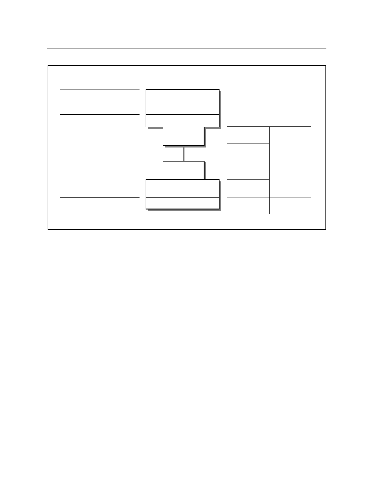
Figure 1 shows an overview of the architecture of the enhanced SuperNode
system.
DMS-100 Family EIU User Guide TELECOM12
Page 24

24 Chapter 1: Introduction to the EIU
Figure 1 Overall architecture of enhanced SuperNode system
SLM
DMS-core
DMS-bus
Network IOC
SOS UNIXSOS SOS
9-track tape
FP
(flexible
file system)
AP
(provisionable
computing)
Communications server
(flexible data
communications interface)
DMS-bus interface and expansion
T wo methods are used to interface processing engines to the DMS-bus. Direct
links between the processors and the DMS-bus is the primary method for
establishing this connection. A secondary method involves the LPP, which is
used to fan out the message switch (MS). By having two methods, the DMS100 switch has the flexibility for provisioning software functions to processors
based on price, performance, and packaging criteria.
AP
(provisionable
computing)
Ethernet
X.25
EIU
Workstation
The LPP extends the MS fanout within a single cabinet. This fanout is
accomplished by using a second-level MS pair to provide switching, and by
extending the messaging capability through an extended messaging bus. These
297-8991-910 Standard 03.01 August 1999
Page 25

Chapter 1: Introduction to the EIU 25
second-level message switches are referred to as local message switches
(LMS).
The frame transport bus (F-bus) is a 32-Mbit/s messaging bus that resembles
the MS in its protocol. The use of a narrower data path allows access to two
buses through a single backplane. This feature lets a single processor card
connect to both planes of the LMS and to survive faults on one plane. Links
interconnecting planes of the LMSs are provided to allow transparent message
rerouting in the case of single faults.
Note: Because the interconnecting F-bus is a wire bus, it is limited to a
single cabinet.
Inter-message switch links required with LPP
Inter-message switch links (IML) between the MS planes are also required to
improve robustness. For example, two peripherals (such as an applications
processor and an EIU) can lose communication with each other if they
message through different planes of the MS. In this scenario, assume that one
peripheral is messaging through plane 0 only because of a failure. If the second
peripheral loses its link to plane 0, the two peripherals cannot communicate
even though they can communicate to the DMS-core for maintenance
purposes.
For this reason, there is a pair of IMLs in integrated service node (ISN)
switches. These IMLs are DS512 links that operate at 1024 Kbit/s. Other
improvements to the MS hardware are also required to conform with the ISN
maintenance strategies.
Data communications interface architecture
The overall architecture of the data communications subsystem is based
partially on the premise that the processing and the access method for these
entities must be separate.
For this reason, application processors (AP) have the intelligence to drive the
link protocols. This arrangement allows freedom to change access methods
and allows flexibility in satisfying the processing requirements for each
protocol. The emphasis is on providing locally attached, nonswitched
connections primarily for OAM interfaces. An example of the overall data
flow for the data communications environment is shown in figure 2.
DMS-100 Family EIU User Guide TELECOM12
Page 26

26 Chapter 1: Introduction to the EIU
Figure 2 Ethernet interface data flow
DMS-bus
Messaging path
User AP
(protocol
processing, for
example, terminal drivers)
Given the cost of the SuperNode cabinet infrastructure, providing the standard
hard connection interfaces in this mechanical environment is not possible. For
this reason, interfaces are placed outside the boundaries of these cabinets.
Engineering approaches to LANs also address a similar problem. In LANs, it
is not economic to provide all types of data interfaces at each node on the LAN.
The communications server provides a range of communications services to all
users on the LAN and may be located anywhere on the LAN.
Another major functional requirement that the EIU satisfies is providing
connectivity to commercially available workstations for value-added services.
This requirement is provided through a standard interconnect media. The
majority of these workstations support an Ethernet interface for local area
networking. The EIU also supports this protocol.
Data
communications
processor
(transport
interface)
Ethernet
LAN
Workstations
Communications
server
Data
Terminals
links
The EIU supports packet communication into a LAN. The standards for its
physical implementation are defined in IEEE 802.3. The EIU supports a
10 Mbit/s base band bus type of LAN for broadcast. The LAN uses a carrier
sense multiple access with collision detection (CSMA/CD) method for
arbitrating access to the communications channel.
Lastly, the EIU also provides a protocol gateway into the DMS-100
environment.
297-8991-910 Standard 03.01 August 1999
Page 27

Chapter 1: Introduction to the EIU 27
The Ethernet interface takes advantage of commercially supported peripherals
and functions. These interface devices are selected and qualified for
applications in the DMS-100 switch, with particular attention to hardware
compliance, maintainability, and the protocol set provided. The following
devices are commercially available:
• LAN repeaters to locally extend the range of the LAN
• LAN gateways to extend the range of the LAN to a metropolitan-area
network (MAN) or a wide-area network (WAN)
• asynchronous terminals and printers through communications servers at up
to 19.2 Kbit/s
• synchronous data links through communications servers at up to 56 Kbit/s
• IBM mainframe access through channel interconnect units
• workstations (for example, Sun, HP, IBM), Macintoshs, and PCs
• servers
The EIU is a simplex engine. A simplex engine is sufficient for the EIU
because the facilities that are connected through the EIU are not critical to the
operation of the switch (that is, for call processing). Sets of EIUs may be used
with one or more EIUs available as a warm standby spare. The mapping of the
EIU architecture to the OSI reference model is shown in figure 3 on page 28.
For more information on EIU sparing, refer to “EIU sparing and redundancy”
on page 41.
DMS-100 Family EIU User Guide TELECOM12
Page 28
28 Chapter 1: Introduction to the EIU
Figure 3 EIU mapping to lower levels of the OSI communications model
OSI reference model layers
Data link Layer
Physical Layer
Hardware description
The EIU is based on hardware originally developed for the signaling transfer
point (STP). One of the main components of the STP is the LPP, which is a
frame that can hold up to 36 two-slot ASUs. An LPP containing an EIU is
deployed in a DMS SuperNode switch to establish Ethernet connectivity.
Logical link control
Media access control
Physical signaling
Attachment
unit interface
Attachment
unit interface
Media access unit
Transmission medium
EIU partitioning
EIU software
Ethernet interface hardware
AUI PB
15-conductor
connectorized
cable
External
equipment
RG-58 coaxial
cable
UTP PB
4-wire twisted
pair, LAN hub
Figure 4 on page 29 shows where the EIU is provisionable on the link interface
shelf (LIS). Figure 5 on page 30 shows where the EIU is provisionable on the
single-shelf link peripheral processor (SSLPP).
The EIU consists of three cards provisioned in two slots, as shown in figure 4
and figure 5:
• NT9X84AA, Ethernet interface card (EIC). This processor board
implements most of the media access control (MAC) layer on a single chip.
It has 384 kbyte of high-speed buffer for holding Ethernet packets.
• NT9X85AA, Ethernet interface paddle board (EIP). This paddle board
provides the physical link to the local area network (LAN). The paddle
board implements an unshielded twisted-pair attachment unit interface
(AUI).
• NTEX22BA/BB, Integrated processor and F-bus card (IPF). This
processor board contains a Motorola M68020 processor and 8 Mbyte of
297-8991-910 Standard 03.01 August 1999
Page 29
RAM. The NTEX22CA provides 32 Mbyte of RAM and higher
throughput performance.
NTEX22 also contains a peripheral bus (P-bus) to F-bus interface. The Pbus to F-bus interface connects the processor bus with the frame bus, which
in turn is connected to the local message switch (LMS) through the rate
adaptor.
The IPF card is a common processor card used by almost all ASUs and
runs the Support Operating System (SOS).
Figure 4 Link interface shelf, with 2-slot EIU locations
Top view of LIS shelf
Chapter 1: Introduction to the EIU 29
2-slot ASU
Rear paddle boards Front cards
2-slot EIU
NT9X84NT9X85 Ethernet AUI PB
NTEX22 Integrated processor and F-bus card
DMS-100 Family EIU User Guide TELECOM12
Ethernet interface card
Page 30
30 Chapter 1: Introduction to the EIU
Figure 5 SSLPP, with 2-slot EIU locations
Top view of SSLPP shelf
2-slot ASU
Rear paddle boards Front cards
Ethernet interface card
2-slot EIU
NT9X84NT9X85 Ethernet AUI PB
NTEX22 Integrated processor and F-bus card
Figure 6 shows the placement of an LPP provisioned with an EIU on a DMS
SuperNode switch.
Figure 6 DMS SuperNode switch LPP with an EIU
LMS
plane 0
LMS
plane1
MS 0
MS 1
DS30 links
Figure 7 shows EIU links to the MS on the fiberized link interface shelf (FLIS).
F-bus 0
F-bus 1
EIU
EIU
Ethernet
EIU
297-8991-910 Standard 03.01 August 1999
Page 31

Figure 7 DMS SuperNode FLIS with an EIU
Chapter 1: Introduction to the EIU 31
Bus
plane 0
Bus
plane1
MS 0
MS 1
DS512 links
Ethernet interface card (NT9X84)
The EIC is based on commercial Ethernet interface chips. It supports one
Ethernet communications link and processes all of the level 1 and part of the
level 2 protocols for the Ethernet in hardware.
The card consists of a common message buffer that is accessed by both the
processor and the Ethernet interface chip. On the Ethernet side, an independent
controller uses memory-based data structures to locate and transmit and
receive data from the links. The controller chip is an Advanced Micro Devices
AM7990 LANCE device (a LAN controller for Ethernet) with support devices.
F-bus 0
F-bus 1
EIU
EIU
Ethernet
EIU
The buffer memory is organized as 192 kilowords x 16 bits (384 kbyte) with
parity, and is directly accessible by the processor. Both byte and word access
is supported. The processor and the Ethernet control chip contend for access to
this memory . The architecture of the memory controller ensures that sufficient
memory access bandwidth is allocated to the Ethernet controller, so that
underrun or overrun conditions do not occur during transmission or reception
of a message.
Figure 8 illustrates the memory and buffer architecture.
DMS-100 Family EIU User Guide TELECOM12
Page 32

32 Chapter 1: Introduction to the EIU
Figure 8 Ethernet interface architecture
P-bus
LPP
NTEX22
CPU/IPF
Ethernet
Ethernet physical interfaces
The physical interface to the Ethernet system is defined by the paddle board
located behind the EIC. The interfaces available are described in the following
sections.
Attachment unit interface—NT9X85AA
This card is a 15-pin D-type connector that provides the interface between the
Ethernet controller and the media access unit (MAU). This is the most generic
interface and supported as an industry standard (IEEE 802.3 10Base5
implementation).
Ethernet
memory
controller
Multiport
buffer memory
Ethernet
controller
MAU
Ethernet
coaxial cable
Note: This interface is compatible with all implementations of Ethernet
through external equipment.
The MAU is different depending on the implementation of the LAN.
For a 10Base5 coax LAN, the MAU has coaxial connections on either side
using field installed N-type connectors. The AUI connection is on an adjacent
side. The coax cable is about 0.5 in. in diameter and has a bending radius of
0.5 m and the minimum amount of cable between transceivers is 2.5 m. These
physical restrictions must be taken into account when installing the MAU.
MAUs have a range of 500 m per bus segment which may be bridged together
to form a LAN that is a maximum of 2500 m long. The disadvantages of this
implementation are installation and difficulty of maintenance.
297-8991-910 Standard 03.01 August 1999
Page 33

Chapter 1: Introduction to the EIU 33
For a 10BaseT twisted-pair LAN, the AUI connection is usually on one side
with an RJ-11 telephone jack on the other. Typically, standard office four-wire
circuits are used to connect the MAU to the hub. The hub is an electronic
replacement for the multiple access properties of the coaxial cable. It generates
the broadcast function for each message received. It is usually an AC-powered
unit mounted in a 19-in rack. The hub has either RJ-11 telephone jacks or a
specialized interconnect through a punch-block distribution system.
Typical unshielded twisted-pair (UTP) systems offer a LAN radius of 100 m,
allow cascading of hubs, and may allow the use of other types of interconnect
(fiber or standard coax) to increase the radius. The star configuration, in
combination with the centralized electronic implementation of the LAN
function, allows fault location and isolation capabilities that are more in line
with standard DMS-100 maintenance practices.
Unshielded twisted-pair (NT9X85BA)
This interface contains a UTP MAU and hub integrated onto the paddle board.
The card provides a 4-wire twisted-pair connection externally. Up to four
external LAN devices can be connected to the hub. This development provides
a cost reduction over an OEM 10BaseT LAN configuration and puts
maintenance of the hub more in line with standard DMS-100 maintenance
practices.
Grounding requirements
Isolated system ground (ISG) is not mandatory . The EIU will operate properly
in both ISG and non-ISG environments. This section provides information on
grounding for equipment and facilities associated with the EIU.
ISG issues are most prevalent in the area of Ethernet peripherals. Because
these devices are AC powered, they may violate the ISG requirements. Devices
can be powered from a protected AC source to isolate the frame and logic
grounds and to provide continued service in the event of a commercial AC
power failure.
In addition, the implementation of the AUI is not compliant with the IEEE
802.3 specification. In particular, the shield of the AUI cable is not connected
to logic ground. Instead, the cable is connected to frame ground to satisfy the
ISG requirement. The Ethernet interface is further transformer-isolated in the
transceiver (the MAU) and the shield ground is capacitively coupled to the case
of the unit.
Capabilities, limitations, and restrictions
This section describes the known limitations and restrictions for the EIU.
The operating company can install the EIU only on SuperNode shelves,
including the LPP (but not the 24-slot LPP), FLIS, and SuperNode SE link
DMS-100 Family EIU User Guide TELECOM12
Page 34

34 Chapter 1: Introduction to the EIU
interface shelf (SNSE LIS). Nortel has tested the EIU for installation,
operation, administration, and maintenance on each of these platforms.
EIU hardware capabilities and limitations
The following points describe EIU-specific limitations:
• An Ethernet message is 1518 bytes long, including 128 transmit and 128
receive buffers.
• The EIP (NT9X85AA) implements the unshielded twisted-pair AUI
interface, which provides the physical link to the LAN. The EIC
(NT9X84AA) implements most of the MAC layer.
• Only the 2-card EIU, based on the IPF (NTEX22BA/BB), is supported.
• The 4-Mbyte EIU (NTEX22AA) is not supported.
• The 8-Mbyte EIU, based on the IPF NTEX22BB, is now standard. All
customer sites must upgrade.
• The EIU and the TCP/IP protocols are suitable for connecting low- to
medium-speed peripherals, such as terminal servers and workstations, to
the SuperNode switch.
The EIU acts as an IP router for IP capable nodes such as the DMS-core,
file processors (FP) and application processors (AP). The EIU can perform
this function subject to the limitations identified in this document. The
TCP/IP protocols allow interworking with a very large number of third
party vendor’s equipment.
• The EIU, unlike equipment from many other major manufacturers, can
withstand a broadcast storm
1
or a babbling node. This capability is
possible because of the overload control feature. This capability follows
the standard DMS-100 maintenance philosophy, which states that a node
must be maintainable even under overload conditions.
In a lab environment, it has been demonstrated that a moderately heavily
loaded LAN with broadcast messages caused workstations and a router to
lock up, while the EIU remained functional. The workstations were
overloaded to the point that all activity within the operating system
stopped:
— the on-screen clock stopped ticking
— the cursor did not respond to mouse movements
— keystrokes were ignored
— outgoing LAN activity stopped
1. A broadcast message is issued from a single node and is received and processed by all nodes
on the network. A broadcast storm occurs when a faulty node broadcasts a message to all other
nodes for which it expects a reply. For each reply, the node may in turn issue another broadcast
message causing the number of messages to multiply rapidly until the network is congested.
297-8991-910 Standard 03.01 August 1999
Page 35

Chapter 1: Introduction to the EIU 35
— programs were not aware that a period of time had elapsed
— The router stopped routing packets.
The EIU remained fully functional throughout the broadcast storm test.
Although traffic from the EIU stopped, this stoppage was due to all other
components on the LAN being nonfunctional and there was nothing left for
the EIU to communicate with. The test demonstrated that maintenance
personnel could remote login to the EIU, start a CI process, look at some
OMs, and remote logout. The EIU could also successfully complete an inservice test and could be manual busied, then returned to service after
successfully completing the out-of-service test.
• IP throttling was introduced to address customer concerns on co-residency
of EIUs with other ASUs in an LPP frame. The IP throttling feature
provides partial protection for the DS30 links at the expense of EIU
throughput. Similarly, throttling has been implemented for EIUs on FLIS
and SNSE LIS to protect the links between the MS and EIU from
overloading.
When deployed, fiber SR128 links through the MS will provide enhanced
capacity to alleviate link capacity overload.
• The SNSE LIS and LPP have been product integrity tested with up to eight
EIUs. Capacity engineering rules restrict the number of EIUs supported
per platform to less than eight. Refer toProvisioning Rules for LPP, SSLPP,
and SNSE LIS, System Engineering Bulletin SEB 92-02-001.
• The DMS-100 switch supports a maximum of eight EIUs per switch. Each
of the eight EIUs can be configured on a separate LAN. However, EIUs
configured on the same LAN can provide simple load balancing of IP
traffic between EIUs, and tolerance to failure of a single EIU. For more
information on redundancy and sparing, refer to “EIU sparing and
redundancy” on page 41.
• The EIU can screen IP packets whereby only IP packets from a specified
list of source IP address are accepted into the SuperNode switch and others
rejected. This list of IP addresses is bound in by and is the responsibility of
user applications (for example, EXNDINV).
• OSI and TCP/IP protocols cannot co-exist on the EIU.
• Theoretically, the EIU is capable of routing approximately 350 kbyte/s
with 1536 kbyte packets at the IP level. That measurement equals about 2.5
Mbit/s. This performance measurement is the rate at which the EIU routes
to the F-bus. However, throttling values limit throughput. Refer to
Provisioning Rules for LPP, SSLPP, and SNSE LIS, System Engineering
Bulletin SEB 92-02-001.
DMS-100 Family EIU User Guide TELECOM12
Page 36

36 Chapter 1: Introduction to the EIU
System-wide limitations
The EIU is collocated in an LPP shelf with other ASUs such as the link
interface unit (LIU7) and frame relay interface unit (FRIU). The exact
configuration of ASU-type units depends on the applications. The LPP is
connected to the DMS-bus through eight DS30 links in a load-sharing
arrangement.
Each DS30 has a transfer capacity of approximately 256 Kbyte/s. A single EIU
can route long messages (1518 bytes) from the LAN to the DMS-bus at a rate
that can overload the DS30 and cause the link to fail (SysB state). This link
failure causes traffic to switch to an alternate DS30 link. If the system
maintains the level of traffic that caused the initial failure, each DS30 link
topples one by one until the LPP is isolated from the DMS-bus. Further, as
each DS30 link overloads, all pending messages on that link are lost, including
SS7 messages.
Note: When deployed, fiber SR128 links through the MS will provide
enhanced capacity to alleviate link capacity overload.
The IP throttling feature throttles IP messages to and from the EIU to provide
a measure of protection against DS30 link overload. Application groups can
engineer throttling to permit them to override the defaults. Complete
protection is still not guaranteed due to other message sources, such as SIPC,
MTS, logs, and OMs. Further, multiple EIUs on the same LPP can still
simultaneously send a large message on the same link which, when combined
with other messages in the LMS RX FIFO queue, can still cause an overload.
IP throttling has also been implemented to protect the links between the MS
and EIUs that are on FLIS or SNSE LIS.
A problem common to all ASU types is that the F-bus receive buffers can be
overloaded. If this happens too many times within a certain time interval, the
rate adaptor detects the error and fails the link. Engineering rules are required
to ensure any ASU type is not overloaded. Refer toProvisioning Rules for LPP,
SSLPP, and SNSE LIS, System Engineering Bulletin SEB 92-02-001.
Limitations associated with maintenance
The operating company can datafill a maximum of eight EIUs in the LIUINV
table. That is, the maximum number of EIUs on a switch is eight. As a further
limitation, each LPP can have a maximum of four EIUs. The FLIS can have up
to eight EIUs.
These limitations are not only a datafill issue. Other factors must be studied
before these values can be increased, such as traffic load through an LPP or
FLIS, EMI emissions, and routing issues. Currently , with 8 EIUs and 28 LIU7s
in a 36 processor LPP configuration, the emissions are just within allowable
limits.
297-8991-910 Standard 03.01 August 1999
Page 37

The Ethernet address in the LIUINV table has the format of the Nortel
SuperNode family range of addresses: X000075Fxxxxx, where X is
hexadecimal notation and x is a variable. For more information on MAC
addresses, refer to “Appendix I: Obtaining a MAC address”.
Diagnostics for the EIU test only the Ethernet interface card (EIC) and the
Ethernet interface paddle board (EIP). These diagnostics do not test the AUI
cable. The AUI cable attaches to the paddle board and to a connector in the
bulkhead. An extension of the AUI then runs from the bulkhead to the MAU.
Diagnostics also test the MAU. EIU diagnostics test the EIU’ s connectivity to
the AUI and the MAU up to the HUB.
Lastly , the recor d start command cannot be initiated during a telnet session on
the connected device.
Limitations associated with protocols
Trailers are not supported. T railers are the field on the data packet in which the
system places the “headers”, which normally precede the data, after the data.
Trailers can be negotiated between cooperating systems in an attempt to
improve efficiency.
Chapter 1: Introduction to the EIU 37
In the DMS-core, the protocol stack runs in the SuperNode IP (SNIP)
scheduler class. This includes the IP receive processes and timer functions for
TCP. In all other nodes, the protocol stack runs in CP class. The initial
allocation for SNIP class is 3 percent and an interface is provided that allows
an application to modify this value.
The following sections describe specific limitations associated with protocols.
Routing information protocol
The size of the dynamic routing table is limited to 436 entries. This limitation
is imposed by the current implementation of and the current number of buffer
management system (BMS) buffers reserved for routing information protocol
(RIP) broadcasts. If the routing table overflows the routes at the end of the RIP ,
the system ignores the messages. This situation can lead to unpredictable
routing behavior, such that routes may appear and disappear every 30 s. There
is no warning log to notify the operating company that this errant behavior is
occurring.
RIP Version 1.0 does not support variable-length subnetting. This limitation
means that all subnets that use RIP to exchange routing information must use
the same number of bits in their IP address to identify their subnet. If a subnet
does not adhere to this rule, unpredictable and intermittent loss-ofconnectivity behavior may be experienced on the EIU. RIP-II, which supports
variable-length subnetting, is not implemented on the EIU.
DMS-100 Family EIU User Guide TELECOM12
Page 38

38 Chapter 1: Introduction to the EIU
TCP
Each TCP connection has its own state machine. For the number of allowed
connections, refer to Table 5, TCP connection limits by Supernode subsystem
in this document. There are also SOS limitations in that applications that
require hundreds or thousands of connections are not supported.
Internet Protocol and Internet Control Message Protocol
When an EIU goes ManB or SysB, any qualifying EIU that is available takes
over. The first EIU that failed broadcasts reverse-RIP messages advertising its
loss-of-connectivity to the network. In this way, the routers on the LAN that
are immediately notified of the second EIU takeover.
However, there is a worse case scenario in which the reverse-RIP messages are
lost on the LAN. As a result, the entry for the first EIU must time-out in the
routing table in each router before these routers start sending datagrams to the
second EIU. This time-out can take up to 3 min. This limitation is imposed by
the RIP implementation on the EIU. A possible option is to configure the
routers on the LAN to use only address resolution protocol (ARP) and not RIP
to communicate with the DMS-100 switch. However, the ARP-cache time-out
on the router must be set to a low value (1 min is the recommended time).
All subnet size combinations are permitted in table IPNETWRK. However, the
subnet size in the DMS-100 switch must be the same as the subnet size of the
LAN to which the DMS-100 switch is connected. This requirement is a result
of the limitation of the RIP version 1.0 implementation in the EIU. The IP
subnet must be allocated for each DMS-100 switch. Refer to “Addressing” on
page 50.
Feature packaging
Feature packaging applies to software loaded on the DMS-core. In general,
these packages provide the central maintenance functionality for the new
remote processors and the protocol software.
Prior to CSP02, the feature packages for the software resident in the DMS-core
are summarized in table 1.
Table 1 DMS-Core feature packages
Package Title Description
NTXF05AA Ethernet interface unit The is the basic package
needed to datafill and
maintain the EIU. No protocol
software is included in this
package.
(Sheet 1 of 2)
297-8991-910 Standard 03.01 August 1999
Page 39

Chapter 1: Introduction to the EIU 39
Table 1 DMS-Core feature packages
Package Title Description
NTXF19AA TCP/IP This package is the protocol
software from the transport
layer down to the link layer.
NTXF19AA uses NTXF05AA.
NTXS11AA FTP This package is the standard
FTP client and server
software. NTXS11AA uses
NTXF19AA.
NTX70AA Telnet/RMAP This package is the standard
telnet server for remote MAP
(RMAP) access.
(Sheet 2 of 2)
Software for peripheral processors is controlled through package lists that
define the entities for a specific load. The EIU may have several loads
depending upon the applications resident on it.
As of CSP02, the EIU-related software is packaged in LANCOMM. Software
is available with TL_ALL LCF. EIU-related software is provided as part of
order code TEL00001.
EIU provisioning requirements
The provisioning rules for the total numbers of EIUs depend on the following
requirements:
• the applications running on the EIUs
• the total application capacity required for all EIUs on the switch
• the level of redundancy required by these applications
The provisioning requirements are subject to the maximum limit of eight EIUs
per switch.
The following sections describe the provisioning limits for the new
components.
DMS-bus inter-MS provisioning
Each message switch in an IML requires an NT9X17DA port card and an
NT9X20BB DS512 fiber paddle board.
Card position is not restricted. However, the cards associated with a link must
use the same slots in each MS. For example, if the cards in one MS are
provisioned in slot 21 (that is, the NT9X17DA is in 21F and the NT9X20BB
DMS-100 Family EIU User Guide TELECOM12
Page 40

40 Chapter 1: Introduction to the EIU
is in 21R), the cards in the MS at the other end of the link must also be
provisioned in slot 21. This example is shown in figure 9.
Figure 9 Example of DMS-bus intermessage switch configuration
NT9X20BB DS512
fiber paddle board
MS
NT9X17DA port card
NT9X20BB DS512
Intermessage switch link
Intermessage switch link
fiber paddle board
MS
NT9X17DA port card
The following cards must also be provisioned on each switch:
• a minimum of 16 Mbyte of memory using one of the following card
configurations:
— one NT9X13DB CPU card and one NT9X14DB memory card
— one NT9X13NA CPU card
• one NT9X49CB MS tracer card
DMS-bus external MS provisioning
Just as the SuperNode core requires access to the DMS-bus, so do peripherals.
Therefore, DMS-bus port engineering is required.
297-8991-910 Standard 03.01 August 1999
Page 41

Chapter 1: Introduction to the EIU 41
The information in table 2 defines the port requirements for EIU installation.
Table 2 DMS-bus port engineering requirements for peripherals
Peripheral Message Switch Comments
links per plane Port Card Paddle Board
LPP (DS-30) 4 NT9X17AA NT9X23BA 1 LPP requires 1
MS port card
EIU provisioning
Provisioning of EIUs is application dependent. The number of EIUs required
and their configuration is determined by a combination of product and
software criteria. EIUs are not provisioned on a switch unless required by the
application.
Where possible, provision two or more EIUs connecting to a single LAN to
improve reliability. This redundancy may not be required if duplication is
provided at a higher system level (for example, duplicate LANs).
Observe the following provisioning rules:
• although the maximum number of EIUs in a switch is limited to eight
(limitation imposed by software), the actual number that you can provision
per platform is determined by engineering rules (refer to Provisioning
Rules for LPP, SSLPP, and SNSE LIS, System Engineering Bulletin SEB
92-02-001
• each EIU requires one LIU position (two slots) in a 36-position LPP
• each EIU has a fixed memory capacity; the NTEX22BB contains 8 Mbyte
of RAM, and the NTEX22CA contains 32 Mbyte of RAM
For more information on datafill, refer to “Chapter 3: EIU datafill”. For more
information on maintenance impact on spares, refer to “EIU sparing
requirements” on page 101.
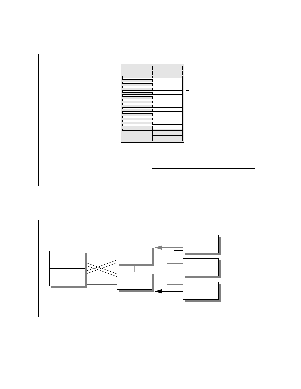
EIU sparing and redundancy
The DMS switch and the EIU support load balanced routing. Characteristics
related to provisioning and options are described in the following points:
• In table IPNETWRK, one EIU is defined as the default for the CM.
• In table IPROUTER, all EIUs are defined.
• Maintenance software ensured that all EIUs are aware of the states of all
other EIUs. States are known for the following:
— links between the EIU and the LAN-side subnet
— links between the EIU and the SuperNode-side subnet
DMS-100 Family EIU User Guide TELECOM12
Page 42

42 Chapter 1: Introduction to the EIU
— the EIU state
• During normal operation, the default EIU routes all messages to the CM.
If there is a problem with the default EIU or its links, the following occurs:
— the default EIU advertises to the network that it is no longer available
(or in the event of a LAN-side link failure, the neighboring routers
cannot reach the default EIU)
— another provisioned EIU advertises that it is the router (net hop) to the
SuperNode-side subnet and the CM
• During normal operations, if there is a problem with the non-default EIU
or its links, there is no impact on service unless the default EIU
experiences problems, in which case the SuperNode subnet is isolated
from the LAN-side subnet until one of more EIUs are brought back into
service.
Applications running on the EIUs must have sparing defined at the application
level.
Billing
EIUs do not directly affect billing functions.
Service orders
The EIU does not affect service order functions.
User interface characteristics
The EIU uses the existing peripheral user interface (UI) based on the DMS
MAPCI. The MAPCI includes additions to the PM level of the MAP display
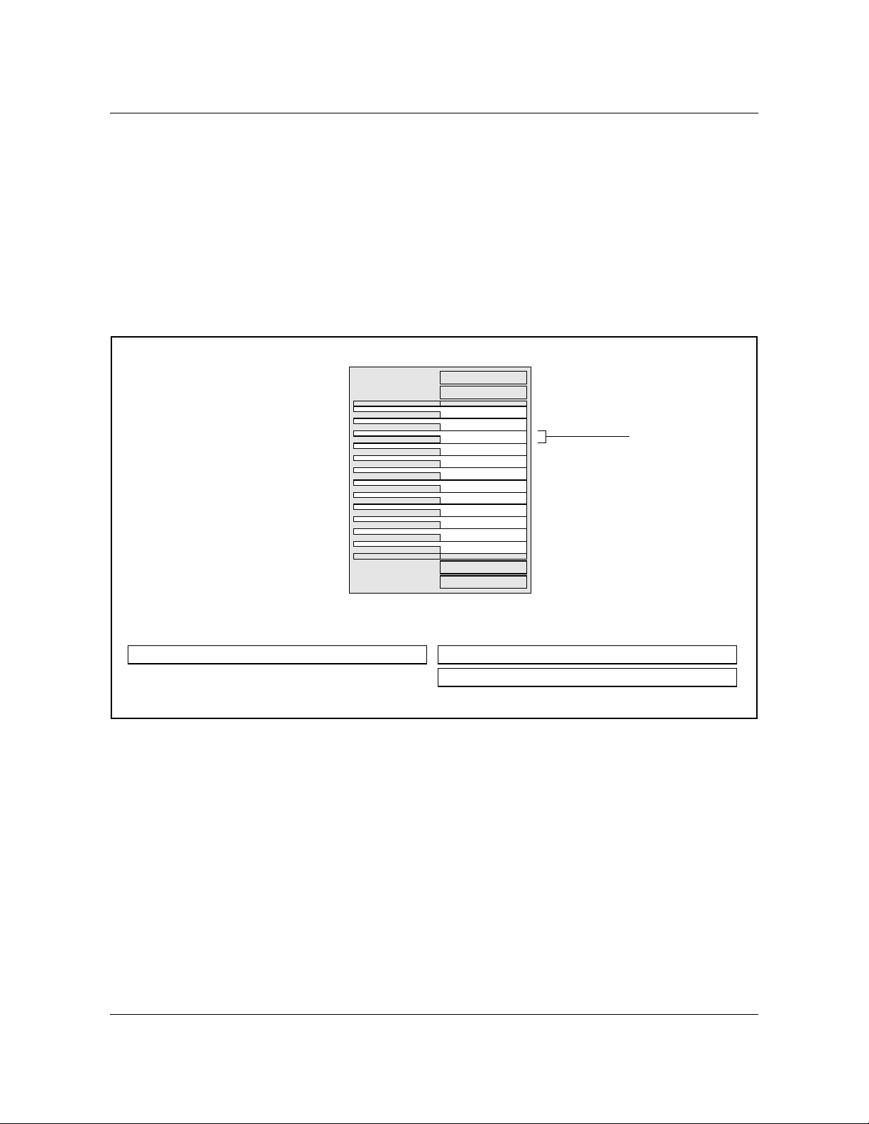
to include the new hardware components. Figure 10 shows the hierarchical
relationship for the MAP levels used for the components.
Figure 10 MAP display level hierarchy
Existing
peripheral
modules
PM level
EIU level EXND level
(LAN devices)
297-8991-910 Standard 03.01 August 1999
Page 43

Logs, alarms, and OMs
In general, the subsystems that generate logs, alarms, and OMs do not have
significant changes apart from the standard DMS-100 reporting sub-systems.
Log reports
All logs from the EIU conform to the DMS OAM infrastructure. Log messages
are formatted in the DMS-core for display using the standard DMS log system.
Alarms
The EIU uses the DMS alarm system to report faults. Alarms are raised by
major maintenance state changes (usually brought on by hardware problems or
overload conditions). In addition, the MAP interface displays a composite
alarm banner across the top of the screen. This banner displays alarms with the
most urgent priority; as maintenance personnel clear the highest priority
alarms, next in priority display for each subsystem. In a healthy DMS-100
switch (that is, operations are normal), there are few alarms occurring.
Chapter 1: Introduction to the EIU 43
CAUTION
Possible loss of information
If a telnet session drops, logs and OMs may be lost.
Operational measurements
The EIU uses the DMS OM collection system to collect and distribute
operational measurements. The DMS OM subsystem also generates simple
reports. OMs can be transferred to “down-stream” processors for more
detailed analysis.
In general, operational measurements can be used to determine performance
and capacity in operational components. General types of operational
measurements gathered by the switch include the following:
• error counts
• I/O counts (operations completed)
• CPU occupancy
DMS-100 Family EIU User Guide TELECOM12
Page 44

44 Chapter 1: Introduction to the EIU
297-8991-910 Standard 03.01 August 1999
Page 45

Chapter 2: EIU messaging protocols
This chapter describes the Ethernet interface unit (EIU) software architecture:
• SuperNode software architecture
• protocol engineering
• Internet Protocol (IP) throttling
CAUTION
Possible loss of network security
Using the Ethernet interface unit (EIU) and a telnet or file
transfer protocol (FTP) session to establish a maintenance
and administration position (MAP) session can introduce a
security risk to both the DMS node and its subtending
network.
When establishing and operating a MAP session in this way,
there is limited security for clear text (user identification and
passwords) and for Internet Protocol (IP) addresses for
screening. This limited security makes an open local area
network (LAN) vulnerable to entry by unauthorized persons.
45
Nortel recommends that the operating company, as a
minimal precaution, integrate intermediate security servers
with encryption to avoid unauthorized access to the switch.
For alternative approaches, contact your Nortel
representative to discuss state-of-the-art secure OA&M data
communications equipment products.
By using the EIU, telnet, and FTP software, the operating
company assumes any and all risks associated with the
implementation and use of this hardware and software.
DMS-100 Family EIU User Guide TELECOM12
Page 46

46 Chapter 2: EIU messaging protocols
Software architecture
The protocol stack supported on the DMS-core includes the following:
• bootstrap protocol (BOOTP)
• file transfer protocol (FTP)
•IP
• telnet
• transmission control protocol (TCP)
• user datagram protocol (UDP)
• simple network management protocol (SNMP)
Software architecture also includes key protocols such as address resolution
protocol (ARP), Internet control message protocol (ICMP) and routing
information protocol (RIP)
Figure 11 shows the structure of the DMS-100 switch EIU protocol stack.
1
.
1. EIU only.
297-8991-910 Standard 03.01 August 1999
Page 47

Figure 11 SuperNode TCP/ IP protocol stack
Chapter 2: EIU messaging protocols 47
Base_Tel-7
FTP TELNET RIP
TLI (transport layer interface)
20, 21
TCP UDP
ARP
FTS ETHERNET
23
GNI (generic subnet interface)
161, 162
IP
BOOTPSNMP
67, 68
ICMP
The message flow between SuperNode nodes, and between SuperNode nodes
and external Ethernet LAN, is shown in figure 12 in this section.
520
DMS-100 Family EIU User Guide TELECOM12
Page 48

48 Chapter 2: EIU messaging protocols
Figure 12 SuperNode TCP/IP message flow
DMS-core
Applications
TCP/UDP
IP
FTS
DMS-bus
EIU
Applications
TCP/UDP
IP
FTS
File processor
Applications
TCP/UDP
IP
FTS
Ethernet
Ethernet LAN
Workstation
Applications
TCP
IP
Ethernet
297-8991-910 Standard 03.01 August 1999
EIU as router
Inter-host connections
Page 49

Supported protocols
The EIU software is designed such that the EIU can be configured to run as
one of the following:
• Internet host: EIU is involved only in supporting applications such as
Message Detail Recording for SS7 (MDR7)
• Internet router: EIU is involved only in forwarding IP packets between
SuperNode and Ethernet LAN
• Internet host and Internet router: EIU forwards IP packets between
SuperNode and Ethernet LAN, as well as supporting a local application
such as MDR7 on the EIU
• Interface: EIU is similar to an internet router. The difference is that the
Supernode can be configured on an existing Ethernet subnet
Appendix F, “EIU supported configurations” in this document contains
diagrams of these configurations.
The following sections describe the protocols supported by the DMS-100
switch.
Chapter 2: EIU messaging protocols 49
Boot protocol
Boot protocol (BOOTP) is a UDP/IP bootstrap protocol that allows a client
machine to discover its own IP address, the address of a server host, and the
name of a file to be loaded into memory and executed. A BOOTP server has
been implemented for the CM, a BOOTP relay agent for EIUs and a BOOTP
client for FPs (FEAT.AR1295).
BOOTP can be used to configure three types of IP hosts:
• Nodes that reside on the DMS FPs. Once table IPNETWRK is datafilled,
each FP that does not already have an IP address sends a BOOTP request
to the CM. The latter allocates an address for the FP, adds a tuple in table
IPHOST with 20 TCP endpoints, 4 FTP client sessions, and 4 FTP server
sessions, and sends a BOOTP reply back to the FP . Refer to “TCP” on page
36.
• Nodes that are part of the DMS product but not connected to the DMS-100
switch can be configured on an Ethernet LAN using EIUs. Such nodes
must be on the same subnet as the LAN side of the EIUs to be configured
through the BOOTP server on the CM, except if the maximum hops count
accepted by the relay agent and server is increased. The internal database
for BOOTP on the CM must be populated with information about such
nodes, for example by putting the required information in table
EXNDINV. The relay agents on EIUs forward relays requests and replies
between the clients on the LAN and the BOOTP server on the CM.
• Nodes that are part of the DMS product, but that are connected to the DMS100 switch through an Ethernet LAN directly to the CM (that is, the CM
DMS-100 Family EIU User Guide TELECOM12
Page 50

50 Chapter 2: EIU messaging protocols
has an Ethernet card). Such nodes have to be on the same subnet as the CM
to be configured through the BOOTP server on the CM, except if the
maximum hops count accepted by the server is increased.
File transfer protocol
File transfer protocol has been implemented on all the SuperNode-based nodes
including CM.
FTP implementation contains client as well as server software. The client
software lets the user application connect to a remote FTP server. The server
can be on any node within the SuperNode switch or a node external to the
SuperNode switch. The communication with the external node is through the
EIU. At least one EIU must be in-service in order to connect to an external
node. The SuperNode FTP server software listens to the incoming requests for
connection from a client FTP.
An FTP client has been implemented for launching manual FTP client sessions
from any SuperNode-based node to any node external or internal to the
SuperNode switch. The manual FTP can be invoked by issuing the following
command:
> ftp ‘<nnn.nnn.nnn.nnn>’ [x]
where
nnn.nnn.nnn.nnn is the IP address of the FTP server
x x is an optional port number
Observe that the IP address is enclosed within single quotes. For manual FTP,
a path name in lower case must be enclosed within single quotes. If the path
name is not enclosed within quotes and starts with a slash character(/), the path
name must be prefixed by a colon character (:). These restrictions are specific
to SuperNode CI.
There are three separate file systems supported by FTP:
• SFDEV (on all nodes)
• SLM volumes on CM
Also, access to the IOC is available. SLM volumes and SFDEV are recordoriented file systems, whereas FTFS volumes are byte-stream oriented.
Therefore, take extra care to identify the record lengths while transferring files
to a record-oriented file system.
For example, LOAD68K files require 256-byte fixed-length records. UnIPLed
images are stored as 512-byte fixed-length records. IPLed images need 1020byte fixed-length records. The record length can be set either automatically or
manually . If the file extension is in a prescribed form, the system automatically
297-8991-910 Standard 03.01 August 1999
Page 51

Chapter 2: EIU messaging protocols 51
detects and sets the record length. To manually set the record length, use the
LRECL command. This command changes the record length locally at the
client site and sends the command to the server. The command is applied
locally, regardless of the server response (negative or positive). Both the
automatic record length detection process and the manual process require that
the file transfer type (ASCII or BINARY) be manually set to the required value
before transferring the file.
ASCII files can also be transferred to the record-oriented file systems. If the
transfer mode is binary , FTP switches automatically to FIXED length records.
If the file size of the file being transferred to the SuperNode switch in binary
mode is not a multiple of the current record length, the last record is padded
with spaces. This is a file system restriction and has nothing to do with FTP
implementation. This restriction can be eliminated by providing a separate
QUOTE command for FTP which toggles the record type (FIXED/VAR) in
binary mode. For files that do not meet the above criteria, the QUOTE
command can be issued to switch to VAR record length for binary transfer
mode.
Volume listing is available via any FTP connection to the DMS-100 switch. T o
list the available volumes when connected to the DMS FTP server, type the
following command:
ws>ls /
The system automatically capitalizes filenames when it is connected to a DMS
FTP server. The DMS SuperNode filename convention is to use an uppercase
format for all files even though it provides for lower case. Therefore, any
filenames included with commands sent to the DMS FTP server are
automatically capitalized. If a filename needs to be lowercase, enclose the
filename in single quotation marks to prevent automatic capitalization of the
filename.
Since the DMS SuperNode system does not have a global security concept, the
FTP server implementation contains a security mechanism. This mechanism
relies on the applications to inform about the potential userIDs and passwords
for valid FTP logins from remote FTP clients. The applications reserve a
number of FTP server sessions and provide a set of valid userIDs and
passwords. This information is kept as a database and is compared with the
userID-password combination whenever a remote client tries to login.
The activation and deactivation of the FTP layer on a node is controlled by the
datafill in table IPHOST. The tuple for a particular node contains the number
of server and client sessions allowed on that node. These numbers map
correspondingly into simultaneous FTP server and client processes.
DMS-100 Family EIU User Guide TELECOM12
Page 52

52 Chapter 2: EIU messaging protocols
Internet Protocol
The IP control software supports the IP logic, which provides a connectionless
datagram service between hosts. The IP software is designed such that the
same modules provide IP host and IP router functionality. The IP layer
interfaces with the following:
• transport layer protocols like TCP and user datagram protocol (UDP) for
providing data flow between transport layer and data link layer
• address resolution protocol (ARP) for resolving IP address to subnet
address
• Internet control message protocol (ICMP) for handling IP control
messages to and from other IP nodes
The IP routing table is maintained through static datafill in IP tables in DMScore and through dynamic routing information available either through
Routing Information Protocol (RIP) or ICMP redirect message.
The IP throttling process is responsible for transmitting queued IP datagrams
to destination nodes, based on the IP throttling configuration in the IP tables in
DMS-core.
T elnet
T elnet is an application protocol for remote terminal access. T elnet software is
implemented in two parts:
• a server that resides on the accessed (host) computer
• a client that resides on the accessing (remote) computer
The server program listens at a known port for connection from clients. After
a connection is established, the client redirects all keyboard input to the server,
which passes it on to the accessed program. The server intercepts all program
output, and redirects it to the client which prints it on the client machine screen.
The DMS-100 telnet server implementation has the following features:
• remote access to the DMS-100 switch through telnet
• increased maximum number of simultaneous telnet sessions supported on
the DMS-100 switch
• logs that report on the telnet software
• dynamic assignment of telnet sessions
T elnet functionality has been implemented in the DMS-100 switch to provide
access to the CI and the MAPCI, which are running on a DMS-core (CM),
from a workstation or other FTP-capable devices on an Ethernet LAN.
297-8991-910 Standard 03.01 August 1999
Page 53

Chapter 2: EIU messaging protocols 53
The MAPCI supports asynchronous output to both the scroll area and a “full
screen” area. The input, however, is buffered in a line-by-line mode. This
combination of features requires that the telnet client perform echoing of input
characters.
The telnet server translates MAP display updates into VT100 character strings
and sends them to the telnet client at the remote end. Telnet clients must
directly connect to the CM using the CM address.
Transmission control protocol
TCP is a reliable transport layer protocol that provides communications
services to various applications like telnet, FTP, and so on. TCP can reside on
all the nodes capable of running Internet software. SuperNode TCP
implementation is able to interoperate with most of the industry-standard TCP
implementations.
User datagram protocol
UDP protocol provides connectionless transport protocol services unlike TCP,
which provides connection-oriented transport services. The original
SuperNode application for UDP is routing information protocol (RIP) on an
EIU. The IP route path display tool is also using UDP for intra-SuperNode
messaging between processes on different nodes. The UDP is designed such
that it can use IP fragmentation and reassembly functions to support UDP
datagram size of up to 4 kbyte.
Address resolution protocol
The address resolution protocol (ARP) protocol implements the address
resolution protocol, which provides dynamic binding between IP address and
a physical hardware address. ARP resolves IP address-to-Ethernet or MAC
address translation through ARP protocol running on an EIU. The IP address
to frame transport address (FTA) translation is done in ARP through simple
static table lookup.
Internet control message protocol
The ICMP software provides the IP status and error-reporting mechanism,
which is very closely coupled to IP. The ICMP messages handling in
SuperNode is limited to a few specific messages. The ICMP echo and response
messages are handled to provide ping capability . The ICMP redirect is handled
to provide routing table updates to SuperNode hosts from the dynamic routing
information on the EIU. TCP is notified of ICMP source quench messages.
Routing information protocol
The industry standard RIP is implemented for an EIU to enable it to participate
in the exchange of dynamic routing information with other IP routers on the
Ethernet LAN. The dynamic routing information is required on the SuperNode
to be able to route datagrams to hosts on distant LANs.
DMS-100 Family EIU User Guide TELECOM12
Page 54

54 Chapter 2: EIU messaging protocols
Upon receiving RIP update from either another EIU or IP router on the LAN,
the RIP software updates internal IP routing table. According to RFC1058,
RIP response messages are transmitted every 30 s to Ethernet LAN.
Addressing
Within a single SuperNode switch, multiple hosts and multiple applications
within a single host may simultaneously request TCP/IP services. To provide
for application address uniqueness across the network, the following TCP/IP
address allocation scheme is used:
• TCP/UDP provides individual PORT numbers to distinguish between
applications in the same host.
• Each host processor in the Internet SuperNode switch is assigned a unique
IP address. This is a logical address, and when concatenated with TCP port
number, forms a unique network end-point or “socket”.
• A unique IP address is required per hardware device.
• Within the network, each node is physically identified by its own unique
physical hardware address. The logical IP address is translated to a
physical hardware address prior to datagram delivery to the destination
node.
• Within a SuperNode switch, each node such as DMS-core, FP, and EIU has
a unique FTA, which is the physical hardware address on the SuperNode
subnet. The EIU also has a media access control (MAC) address, which
uniquely identifies it on the Ethernet LAN.
• IP broadcast is not supported on the SuperNode subnet since the physical
layer does not support this.
MAC addresses
A unique media access control (MAC) address is assigned to each EIU through
table control datafill in table LIUINV. The norm within the industry is that the
MAC addresses are hard-coded in ROM. The EIU is different from industry
norm in this case. There is a flexibility of assigning the MAC address to the
EIU and at the same time the flexibility can result in problems if the addresses
are not assigned uniquely to the EIUs.
Only 48-bit MAC addresses are supported by the SuperNode switch.
For more information on MAC addresses, refer to “Appendix I: Obtaining a
MAC address”.
Internet addresses
The logical Internet address is analogous to physical or subnet addressing in
which each host is assigned unique integer address called the Internet address
or IP address. The Internet address integers are not assigned randomly , but are
assigned to nodes in such a way that Internet routing is more efficient. Refer to
297-8991-910 Standard 03.01 August 1999
Page 55

Chapter 2: EIU messaging protocols 55
“Appendix E: Understanding IP and IP addressing” for more information on
Internet addressing.
The IP address features and restrictions within the SuperNode switch are as
follows:
• The Class A, B, and C address schemes are supported. The Class D and E
schemes are not supported.
• The IP addresses for all SuperNode hosts are assigned through DMS table
control (tables IPNETWRK, IPROUTER, and IPHOST).
• The IP addresses for all SuperNode hosts are on a single subnet.
• The EIU is assigned two IP addresses: one to address the SuperNode side
subnet and other to address Ethernet LAN side subnet. Both EIU addresses
cannot be assigned on same subnet number. Refer to figure 13 in this
chapter.
• The EIU Ethernet side IP address MUST be the same class and network as
the SuperNode side.
• The SuperNode node IP address can be changed at any time. However,
UDP/TCP applications are affected.
• The EIU host application is addressed from within the SuperNode switch
or from external LAN workstations by addressing the EIU SuperNode side
IP address. The exception is the routing information protocol, which uses
the LAN side IP address.
DMS-100 Family EIU User Guide TELECOM12
Page 56

56 Chapter 2: EIU messaging protocols
Figure 13 Typical configuration for LAN and SuperNode subnets
CM
SuperNode-side subnet
EIU
LAN-side subnet
EIU
For more information on IP addresses, refer to “Appendix H: IP network
number requests” and “Appendix E: Understanding IP and IP addressing”.
How to get IP addresses for SuperNode
T o ensure that the network portion of an IP address is unique, all IP addresses
are assigned by a central authority, the Network Information Center (NIC).
The central authority assigns the network portion of the IP address and
delegates responsibility for assigning host addresses to the requesting
organization.
It is essential for the NIC to assign IP addresses for networks that are attached
to the connected Internet. An individual organization may assign arbitrary IP
addresses without contacting NIC, but only if their network is not connected
to the public Internet. However, experience has shown that it is unwise to apply
this kind of arbitrary addressing scheme. Arbitrary schemes prevent future
interoperability and may cause significant problems and down time when
converting to NIC-assigned addresses in future. It is strongly recommended
that the operating company obtain official Internet addresses from the NIC.
What is the SuperNode network topology?
The network consists of a SuperNode switch and other third-party equipment
such as HUBs and workstations. Third party routers may be required for
distant LANs or for fault tolerant network architecture. Based on network
topology, following information may be required:
297-8991-910 Standard 03.01 August 1999
Page 57

Chapter 2: EIU messaging protocols 57
• the IP address class
• the IP address subnet size based on number of subnets and the maximum
number of hosts per subnet (also, consider future expansion of the
network)
• the IP addresses for HUBs and routers
• the dynamic routing strategy (only RIP is supported on the EIU)
• network security (if the network is connected to public network such as the
Internet, security consideration is vital)
Routing
The IP is a network layer protocol using the ISO seven-layer model. One of the
key responsibilities of the network layer protocol is to route messages from the
source node to destination nodes. The SuperNode IP works in a somewhat
complex inter-networking environment where the routing decision is not
always simple.
The IP routing algorithm must route messages from SuperNode hosts to the
following:
• internal SuperNode SOS and UNIX-based hosts
• external-to-SuperNode hosts such as workstations
When the destination host is not attached to the SuperNode network
2
, IP must
route messages to a neighboring IP router. In this way, IP forwards route
messages toward the final destination. SuperNode connectivity to external
hosts is possible through EIUs. The EIU, in this context, is referred to as an IP
router. Generally, IP routers have more than one network interface (the
network interface is defined as the node’s connectivity to the underlying
network, whether it is Ethernet or FTS), to allow IP messages to pass from one
network to another. The IP router may also provide connectivity to networks
with distinct architectures. The EIU is one such IP router.
The EIU acts as the IP router between the SuperNode hosts (through the FTS
network interface) and the Ethernet LAN (through the Ethernet interface). The
EIU receives and forwards messages between the Ethernet LAN and the
SuperNode hosts. Some unique characteristics of SuperNode IP routing are as
follows:
• IP messages destined from one SuperNode host to another SuperNode host
within same SuperNode are sent directly without any intermediate nodes
as routers or gateways.
• IP messages destined to hosts on the LAN are sent through one of the
available (in service) EIU IP routers connected to that LAN.
2. A SuperNode network is the network of SuperNode hosts reachable through FTS.
DMS-100 Family EIU User Guide TELECOM12
Page 58

58 Chapter 2: EIU messaging protocols
• Upon failure of any one EIU IP router, the traffic is switched over to
another available (in service) EIU IP router on the same LAN.
• IP routing handles a mix of EIU IP routers and EIU hosts on the same
LAN.
• A simple load balancing scheme between multiple EIU IP routers is
provided. The load balancing scheme sets specific EIUs as primary routers
for the outgoing data. Incoming data is load balanced by specific EIUs that
proxy for host nodes within the SuperNode subnet. As host nodes are
provisioned in table IPHOST , the load balancing scheme is updated. Load
balancing is also updated when nodes go in and out of service.
• The EIU does not route messages between nodes on the same or distinct
LANs. The purpose of an EIU is to provide SuperNode connectivity to the
LAN. It is not intended to act as a router between two Ethernet LANs. The
EIU, however, routes messages to another EIU SuperNode host address if
the other EIU is configured as a host and is connected to a different
Ethernet LAN subnet.
• The IP routing software is identical on all SuperNode nodes, including an
EIU.
• The optional RIP (version 1) is implemented on the EIU to participate in
dynamic routing information exchange. RIP allows the SuperNode switch
to route messages to hosts on distant LANs (nodes not directly connected
on the LAN where EIUs are connected).
• EIUs use proxy ARP for other SuperNode IP hosts and for host EIUs on
other Ethernet LANs.
• When an EIU is ISTb (NA), it is still connected to the Ethernet LAN and
responds to packets received over the LAN. The EIU is aware that the
connection to the SuperNode switch is not available. Awareness is
achieved through the EIU by issuing a reverse RIP to neighboring routers
to indicate that the EIU can no longer route to the SuperNode subnet.
A typical SuperNode network topology that is currently supported is shown in
figure 14 in this chapter.
297-8991-910 Standard 03.01 August 1999
Page 59

Figure 14 An example SuperNode Ethernet
Chapter 2: EIU messaging protocols 59
CM
MS
LMS
EIU100
EIU101
Ethernet LAN
Router
APUX10
LIU7
APX
LMS
EIU200
EIU201
Ethernet LAN
APUX20
LIU7
Router
Ethernet LAN
Workstation
Workstation
DMS-100 Family EIU User Guide TELECOM12
Page 60

60 Chapter 2: EIU messaging protocols
Routing tables
The IP routing table structure is briefly explained here. The knowledge of IP
routing tables is critical in understanding SuperNode IP routing issues.
The SuperNode IP routing information is organized locally on all hosts in two
separate tables. One table determines a routeset from a given destination IP
address. An example of this table is shown in table 3. A second table is used
to determine the actual next hop IP address from the routeset derived from the
first table. An example of this table is shown in table 4.
Table 3 IP routing table
Destination Subnet Mask Routeset Type of Route Subnet
47.12.0.0 255.255.240.0 {1, 0, 0, 0, 0} Gateway SuperNode
47.148.0.0 255.255.240.0 {2, 0, 0, 0, 0} Gateway SuperNode
0.0.0.0 0.0.0.0 {2, 1, 0, 0, 0} Default SuperNode
These two tables are not datafilled through table control, rather they are
derived from control datafill in tables IPNETWRK, IPROUTER, and
IPHOST. Further, these two tables may contain entries from dynamically
learned routes either from RIP on the EIU or from ICMP redirect messages on
other nodes.
Table 4 IP route list table
Index Type of route list Node Status Address
1 Router EIU 132 * Primary InSv 47.64.64.4
2 Router-Host EIU 131
EIU 133
EIU 205 * Primary
OutSv
InSv
InSv
47.64.64.2
47.64.64.5
47.64.64.3
Each routing-table entry (see table 3) contains a destination IP address, IP
address subnet mask, list of route lists (routeset) that reach the destination IP,
and other fields that indicate type of route and subnet type. The IP routing
algorithm is used to determine the routeset that can reach the destination IP
address.
Each route list table entry (see table 4) contains one route list. The route list is
composed of a list of routers that share common router characteristics. For
instance, all EIU IP routers configured on the same LAN are grouped in one
route list. The primary router is determined in each route list entry . For a given
host node, the primary router is the EIU that packets are sent to. The primary
297-8991-910 Standard 03.01 August 1999
Page 61

router is determined based on the simple load balancing rules and the status of
the router.
IP Screening
Packets destined for the Supernode can be screened at the IP level. If the
source of the packet is determined to be invalid, the packet is dropped by the
EIU. For more information, refer to data schema table EXNDINV in this
document.
Protocol engineering
This section provides information on engineering rules and data for each of the
protocol layers. It also contains discussions on the maintenance of the protocol
stack and its performance.
IP throttling
IP throttle engineering is required to control congestion in the DS30 links. If
the IP throttle is not properly engineered, the robustness of the LMS on which
EIUs are located is compromised. This situation occurs because of the
potentially large number of datagrams transferred between EIUs and
SuperNode nodes across LMS.
Chapter 2: EIU messaging protocols 61
IP (as a network layer protocol that transfers datagrams between EIUs and the
SuperNode nodes) does not have built-in flow control mechanism to provide
throttling. As a result, manual control is required. Table IPTHRON asserts
manual control over IP throttling of datagrams transmitted over DS30 links.
For information on table IPTHRON, refer to “Chapter 3: EIU datafill”. For
more information on IP throttling, refer to “IP throttling” on page 65.
For information on EIU provisioning rules for LPP, SSLPP, and SNSE-LIS,
refer to Provisioning Rules for LPP, SSLPP, and SNSE LIS, System
Engineering Bulletin number 92-02-001, version 01.09.
TCP connection management
The TCP layer provides reliable delivery of the data to its remote peer through
well-defined connections. The connection management for SuperNode TCP is
handled through datafill in table IPHOST. Table IPHOST permits the
operating company to vary the number of TCP connections on a per node
basis.When changing this value, note the following points:
• decreasing the allowed number of connections causes all connections to be
dropped
• existing connections are maintained when you increase the number of
connections
DMS-100 Family EIU User Guide TELECOM12
Page 62

62 Chapter 2: EIU messaging protocols
Maximums are defined for the number of TCP connections allowed on a node,
as shown in table 5. UDP connection maximums are shown in table 6 on page
62.
Table 5 TCP connection limits by SuperNode subsystem
Subsystem Maximum TCP connections
computing module 64
function processor 32
EIU 32
APU 1
Table 6 UDP connection limits by SuperNode subsystem
Subsystem Maximum UDP connections
computing module 32
function processor 32
EIU 32
APU 32
The parameter TCP_CONN controls the number of TCP connections for the
node. The value for this parameter can be changed at any time regardless of the
status of the node. The new value is immediately propagated to the node
concerned, provided the node is in service.
If TCP was in service before the value of TCP_CONN is decreased, the
existing TCP connections are dropped immediately and the users are notified
accordingly. TCP remains out of service until it can reallocate its resources
(control blocks, buffers, and timers) to accommodate the new number of
allowed TCP connections.
If the new value is zero, TCP remains out of service until a nonzero value
number is datafilled for that node.
The DMS-100 switch responds in the same way when the IP address of the
node is modified while the node is in service. In this case, if the number of TCP
connections remains the same or is increased, the reallocation is not required.
If both the IP address and the number of TCP connections are modified, the
consequences are similar to the situation in which only the number of TCP
connections is decreased. The system generates a log for each connection
dropped. This functionality must be exercised very cautiously, since it may
297-8991-910 Standard 03.01 August 1999
Page 63

cause TCP to drop the existing connections, which could cause a temporary
outage of all TCP applications.
FTP session control
Similar to the concept of TCP numbers, FTP sessions (client and server) on
each node are managed by the parameters FTPSVCON and FTPCLCON in
table IPHOST. These parameters control the number of FTP server and client
sessions allowed on a particular node.
There is no maximum limit defined for these numbers, but they are governed
by the number of TCP connections allowed on the node. Since each FTP
session consumes two TCP connections (control and data), the total number of
FTP client and server sessions taken together cannot exceed half the number
of TCP connections allowed on that node. This restriction obviously does not
take into account other TCP applications on the node. The operating company
must ensure that the values in datafill are adequate for all other TCP
applications (telnet, MDR7, ROSP, and so on).
The number of FTP server and client sessions are tightly coupled with the
number of server and client processes respectively. Each server and client
process manages one FTP server/client session. The number of FTP server
sessions also restricts the number of server processes that can be reserved by
the applications for security reasons. The total number of servers that can be
reserved by different applications cannot exceed the number of servers allowed
on the node.
Chapter 2: EIU messaging protocols 63
If the number of client and server sessions for a node in table IPHOST is
modified, the existing sessions are dropped immediately and the FTP client
users are duly notified. FTP layer remains out of service until all the resources
are reallocated to conform to the new datafill. If the number of FTP server and
client sessions is datafilled as zero, FTP cannot provide its services.
This functionality must be exercised cautiously since it causes FTP to drop the
existing sessions, which could cause a temporary outage of all FTP clients and
servers. Similar consequences are observed if the IP address of the node is
modified while the node is in service. Reducing the number of FTP servers
removes defined owner and userID information as necessary . It is up to the user
or application to restore the information when the number of sessions is
increased.
Protocol buffer engineering
The buffer engineering for receiving and transmitting IP packets is a critical
part of the buffer management for the protocol stack. A default number of
buffers is allocated for IP receive and transmit purposes. The buffers are
divided into three categories:
• small (128 bytes)
DMS-100 Family EIU User Guide TELECOM12
Page 64

64 Chapter 2: EIU messaging protocols
• medium (1024 bytes)
• large (1600 bytes)
When the IP layer comes into service, the number of buffers allocated by
default is 10 for the small buffer size and 5 each for the medium and large
buffer sizes. These values are load and application dependent.
When the TCP layer comes into service, it allocates its own pool of transmit
buffers and adds buffers to the common pool of receive buf fers. The common
pool of buffers is used for receiving IP and TCP packets.
The transmit pool owned by TCP is used for transmission of TCP segments.
The TCP transmission mechanism does not consume buffers from the common
pool. The allocation of TCP transmit and receive buffers depends on the
datafill for the number of TCP connections on the node. For each TCP
connection, TCP allocates 3 small, 2 medium, and 1 large buffer for the
transmit side. It adds as many buffers to the common pool of buffers owned by
ICBM for receiving TCP segments.
For example, assume that the number of TCP connections for the node is 10.
Therefore, the total number of transmit buffers allocated is 30, 20, and 10 for
small, medium, and large sizes, respectively. The same number of buffers for
all three sizes are added to the existing common pool owned by ICBM. If the
TCP layer is brought out of service, all the transmit buffers owned by TCP, as
well as receive buffers that are added by TCP to the common pool (owned by
ICBM), are deallocated. Initial allocation of the buffers in the common pool is
a static allocation regardless of the service state of IP layer. For every two
endpoints reserved, TCP allocates a 4-kbyte buffer for compaction.
Buffer allocation is summarized in table 7.
Table 7 Buffer allocation per end point
Protocol Buffer type Number
TCP Receive 1 1518
ICBM common pool 2 1024
Transmit 1 1518
TCP own 2 1024
UDP Receive 1 1518
(Sheet 1 of 2)
297-8991-910 Standard 03.01 August 1999
Size (in
of buffers
3 128
3 128
bytes)
Page 65

Chapter 2: EIU messaging protocols 65
Table 7 Buffer allocation per end point (continued)
IP throttling
IP throttling for LPP
Protocol Buffer type Number
of buffers
ICBM common pool 10 128
Transmit (application must allocate the
number of buffers and size)
(Sheet 2 of 2)
00
Size (in
bytes)
IP throttle engineering is required to control congestion in the DS30 links.
LPPs, SSLPPs, and SNSE-LISs have different throttling requirements, as
described in the following sections.
For more information on datafill for IP throttling, refer to “Chapter 3: EIU
datafill”.
The LPP incorporates additional throttling control for TCP/IP traffic sent over
DS30s between the MS and LPP. Throttling protects against incorrectly
engineered LANs from overloading DS30s with errant TCP/IP traffic.
T able 8 shows the recommended traf fic values for entry into table IPTHRON.
Adherence to these values ensures adequate bandwidth for the IP router
application and protect against DS30 overload. Refer to “Chapter 3: EIU
datafill” for additional information on table IPTHRON.
Table 8 IP throttling values for LPP
Approved BCS BCS36
Approved CSP CSP02 CSP04/05 CSP04 CSP04
Approved S/W TOPS IEC04
IP router
application
ADAS 10 40 40 10 40 25
CDPD 5 5
RMS 10 10
PSN 12 25
(Sheet 1 of 2)
EIU CM EIU CM EIU CM EIU CM
Tx Rx Tx Tx Rx Tx Tx Rx Tx Tx Rx Tx
DMS-100 Family EIU User Guide TELECOM12
Page 66

66 Chapter 2: EIU messaging protocols
Table 8 IP throttling values for LPP (continued)
Approved BCS BCS36
Approved CSP CSP02 CSP04/05 CSP04 CSP04
Approved S/W TOPS IEC04
IP router
application
Note 1:
Note 2:
Note 3:
(Sheet 2 of 2)
Values for DS30 in kbyte/s
EIU = LMS node
CM = SuperNode
IP throttling for SSLPP
EIU CM EIU CM EIU CM EIU CM
Tx Rx Tx Tx Rx Tx Tx Rx Tx Tx Rx Tx
The SSLPP incorporates additional throttling control for TCP/IP traffic sent
over SR256 between the MS and SSLPP.
T able 8 shows the recommended traf fic values for entry into table IPTHRON.
Adherence to these values ensures adequate bandwidth for the IP router
application and protect against overload. Refer to “Chapter 3: EIU datafill” for
additional information on table IPTHRON.
Table 9 IP throttling values for SSLPP
Approved BCS
Approved CSP CSP04/05 CSP04
Approved S/W IEC04
IP router
application
ADAS
CDPD
RMS 10 10
PSN 12 25
Note 1:
Note 2:
Note 3:
297-8991-910 Standard 03.01 August 1999
Values for DS30 in kbyte/s
EIU = LMS node
CM = SuperNode
EIU CM EIU CM
Tx Rx Tx Tx Rx Tx
Page 67

Chapter 3: EIU datafill
This chapter describes the datafill requirements for installing and maintaining
Ethernet interface units (EIU) in an Ethernet network. There are seven data
schema tables required to provision the EIU. The purpose of each table is
summarized in table 10.
Table 10 Summary of data schema tables required for EIU provisioning
Table Description
LIUINV Table LIUINV is the main inventory table for configuring EIUs, and includes card
product engineering codes (PEC), shelf location, default load name, Ethernet
MAC address, and a flag to enable local area network (LAN) heartbeat checking.
IPNETWRK Table IPNETWRK defines the SuperNode subnetwork (IP address class, DMS-
core host address, subnetwork mask, and default EIU). The SuperNode subnet
is derived from the subnet mask and the DMS-core host address.
IPROUTER Table IPROUTER defines the routing functions of the EIUs (SuperNode side and
LAN side IP addresses, and flags to enable address resolution protocol (ARP)
and proxy ARP protocols).
67
IPHOST Table IPHOST defines IP addresses for all IP hosts in the switch. Hosts include
computing module (CM), application processors (AP), file processors (FP),
application processors for UNIX (APUX), and the EIU.
IPPROTO Table IPPROTO defines timers for ARP refresh.
IPTHRON Table IPTHRON defines IP throttling data in kbyte/s for the EIUs and APUs. Table
entries allow favoring of the CM, APs, and FPs. This table protects the DS30 links
in the LPP from traffic overflow, and is needed for messaging.
ENSITES Table ENSITES contains a complete list of all sites referenced in table EXNDINV.
ENTYPES Table ENTYPES contains a complete list of all external node types referenced in
table EXNDINV.
EXNDINV Table EXNDINV lets the maintenance and administration position (MAP) operator
monitor and control nodes that are either attached to SuperNode switches by EIU,
or attached to SuperNode or NT40 switches by an input/output controller (IOC)
X.25 card.
DMS-100 Family EIU User Guide TELECOM12
Page 68

68 Chapter 3: EIU datafill
The following sections describe these tables as they apply to EIU provisioning.
For complete information on data schema, refer to DMS-100 Translations
Guide, 297-8xxx-350.
Interdependency and auto-configuration
Tables IPROUTER and IPHOST are interdependent on each other, as well as
on table IPNETWRK. Whenever a tuple in table IPROUTER is modified, the
corresponding tuple, if any (with the same EIU), in table IPHOST is also
modified and auto-configured. For example, if either the SuperNode side or the
LAN-side IP address changes for an EIU in table IPROUTER table, the
corresponding entry in table IPHOST is configured to reflect the changes made
in table IPROUTER. The changes in the tables are propagated immediately to
all in-service nodes.
Changes made to the IP address component in table IPNETWRK also force
auto-configuration of the IP address components of all the nodes listed in
tables IPROUTER and IPHPOST. The auto-reconfiguration routine validates
the changes made in table IPNETWRK against the current entries in tables
IPROUTER and IPHOST. If the new parameters of IPNETWRK table do not
conform with all the current entries in the other two tables, auto-configuration
is not performed and the reasons are displayed.
Table LIUINV
The validation routine for auto-configuration validates the host IDs of all the
nodes in tables IPHOST and IPROUTER with the new host ID size being
proposed in table IPNETWRK. The changes cannot be made to table
IPNETWRK if the validation for auto-configuration fails. If the changes are
validated for auto-configuration, the modified data in table IPNETWRK is
propagated to all nodes along with the modified data (as a result of autoconfiguration) of tables IPROUTER and IPHOST.
Boot protocol (BOOTP) may automatically datafill the FPs in table IPHOST
even though EIUs are datafilled automatically.
Table LIUINV describes the hardware configuration for application-specific
units (ASU). EIU hardware information is datafilled in this table.
Currently, the system allows a maximum of eight EIUs per switch. EIUs can
be on a single link peripheral processor (LPP) or in multiple LPPs (according
to the limitations imposed by product integrity testing of the engineering rules
in Provisioning Rules for LPP, SSLPP, and SNSE LIS, System Engineering
Bulletin SEB 92-02-001. The location of an EIU on an LPP or on a particular
shelf of the LPP must be carefully considered with respect to LPP engineering
rules. For more information on engineering, refer to “Chapter 1: Introduction
to the EIU”.
297-8991-910 Standard 03.01 August 1999
Page 69

Datafill sequence and implications
The following tables must be datafilled before table LIUINV:
• PMLOADS
• LIMINV
• CARRMTC
• SUSHELF
• LIMPTINV (LIM-based LIU)
• MSCDINV (MS-based LIU)
You must datafill the EIU in table LIUINV before datafilling it in table
IPHOST.
Table LIUINV datafill
Table 11 lists the fields and value ranges used to datafill an EIU in table
LIUINV.
CAUTION
Possible loss of service
Table LIUINV requires that you datafill a unique media
access control (MAC) address for each EIU. Obtain these
MAC addresses from Nortel. Using an arbitrary address for
an EIU may result in loss of connectivity with the Ethernet
network.
Chapter 3: EIU datafill 69
While table 11 provides all the information you need to datafill for EIUs,
complete information on table LIUINV is in DMS-100 Translations Guide,
297-xxxx-350.
Table 11 Field descriptions for table LIUINV for EIU datafill
Field Subfield or
refinement
LIUNAME see subfields
LIUTYPE EIU
(Sheet 1 of 4)
Entry Explanation and action
Link interface unit name
This is the key field, which consists of
subfields LIUTYPE and LIUNO.
This field uniquely identifies the EIU.
Link interface unit type
The Ethernet interface unit (EIU)
replaces the data communication
processor (DCP).
DMS-100 Family EIU User Guide TELECOM12
Page 70

70 Chapter 3: EIU datafill
Table 11 Field descriptions for table LIUINV for EIU datafill (continued)
Field Subfield or
refinement
LIUNO 0 to 511
LOCATION The actual physical location of the EIU.
LOCATION see subfields
CTRL see subfield
CONTROL LIM or MS
Entry Explanation and action
Link interface unit number
Enter the number assigned to the EIU.
This field identifies the shelf and slot
number where the EIU is located
Location
Enter the location of the EIU on the host
link interface module.
This field consists of subfields CTRL,
SHELFNUM, and LIUSLOT.
Control information
This field consists of subfield
CONTROL.
Controlling host entity
Enter MS if the host is a message
switch and datafill subfields MSCARD
and MSPORT.
Enter LIM if the controlling host is a link
interface module and datafill field
LIMNUM.
MSCARD 5 to 23
MSPORT 0 to 3
LIMNUM 0 to 16
SHELFNUM 0 to 3
(Sheet 2 of 4)
297-8991-910 Standard 03.01 August 1999
Message switch card
If the entry in field CONTROL is MS,
enter the message switch card number.
Any entries outside the range indicated
for this field are invalid.
Message switch port
If the entry in field CONTROL is MS,
enter the message switch port number.
Link interface module number
If the entry in field CONTROL is LIM,
enter the host LIM number on which the
LIU resides.
Otherwise, leave this field blank.
Shelf number
Enter the shelf number, at the host LIM,
on which the EIU is located.
Page 71

Table 11 Field descriptions for table LIUINV for EIU datafill (continued)
Chapter 3: EIU datafill 71
Field Subfield or
refinement
LIUSLOT 8 to 31
LOAD alphanumeric
PROCINFO see subfield
Entry Explanation and action
(vector of up to 8
characters)
Link interface slot
Enter the slot number, at the host LIM,
on which the EIU resides.
The EIU occupies two card slots.
The left-most card represents the
logical location of the card.
All the shelves that are datafilled on a
particular controller must be of the
same type (two-slot shelves).
Software load name
Enter the table software load name
applicable to the EIU.
This load is found in table PMLOADS.
Processor information
This field specifies the product
engineering code (PEC) of the
processors used in the LIU.
This field consists of subfield
PROCPEC.
PROCPEC NTEX22BA or
NTEX22BB
NTEX22CA
CARDINFO This field identifies the PEC of EIU
(Sheet 3 of 4)
Processor product engineering code
Enter the PEC of the processor card
used in the EIU as follows:
• NTEX22BA and NTEX22BB are the
PECs for the 8-Mbyte integrated
processor and F-bus interface
cards. The difference between the
NTEX22BA and NTEX22BB cards
is in firmware only, the hardware is
identical.
• NTEX22CA has a 32-Mbyte
integrated processor and F-bus
interface card.
circuit packs. The EIC PEC code is
NT9X84AA and the Ethernet interface
paddle board (EIP) PEC code is
NT9X85AA.
DMS-100 Family EIU User Guide TELECOM12
Page 72

72 Chapter 3: EIU datafill
Table 11 Field descriptions for table LIUINV for EIU datafill (continued)
Field Subfield or
refinement
CARDINFO see subfields
APPLPEC NT9X84AA
PBPEC NT9X85AA
HEARTBEAT YES or NO
Entry Explanation and action
or
NT9X85BA
Card information
This field specifies the card data and
consists of subfield APPLPEC.
Application product engineering code
Enter the PEC of the application card.
Card NT9X84AA is used with EIU
applications.
This field consists of subfields PBPED,
HEARTBEAT, and MAC_ADDRESS.
Paddle board product engineering code
Enter one of the PECs.
Enter NT9X85AA for EIU coax
applications.
Enter NT9X85BA for EIU unshielded
twisted pair applications.
Heartbeat
Enter YES if the EIU expects a
heartbeat indication signal from the
media access unit (MAU) connected to
it; otherwise, enter NO.
MAC_
ADDRESS
(Sheet 4 of 4)
000075F00000 to
000075FFFFFF
EIU MAC addresses
By industry convention, MAC addresses for networking devices are unique
worldwide. In typical networking devices, the MAC address is burned into a
PROM on the circuit pack. However, for EIUs on the DMS-100 switch, the
297-8991-910 Standard 03.01 August 1999
Yes is allowed only if the MAU supports
heartbeat of signal quality error (SQE)
Media access control address
Enter a 12-character hex string
representing the MAC address.
The MAC address is represented in
hexadecimal without any spaces
between digits. The MAC_ADDRESS
must be of the form 000075Fxxxxx.
MAC addresses for EIUs are defined by
Nortel. Refer to “Appendix I: Obtaining a
MAC address” for more information on
MAC addresses.
Page 73

MAC address is datafilled. The operating company obtains the MAC address
from Nortel, and Nortel in turn controls the distribution of the addresses so that
all addresses remain unique. The operating company must ensure that this
address is datafilled correctly for each EIU.
For details on MAC addresses, refer to “Appendix I: Obtaining a MAC
address”.
IP addresses
By industry convention, IP addresses must also be unique. This address is used
at a network level to route information to nodes in a LAN or WAN
environment. IP addresses are regulated by the Network Information Center
(NIC).
For details on IP addresses, refer to “Appendix H: IP network number
requests” and “Appendix E: Understanding IP and IP addressing”.
Sample datafill for table LIUINV
Figure 15 shows sample datafill for table LIUINV for an EIU.
Figure 15 Datafill example for table LIUINV
Chapter 3: EIU datafill 73
LIUNAME LOCATION LOAD PROCINFO
CARDINFO
-------------------------------------------------------------- EIU 117 LIM 1 3 12 ETC0TBM NTEX22BB
NT9X84AA NT9X85AA YES 000075F4C117
Table IPNETWRK
Table IPNETWRK contains information relating to the SuperNode
subnetwork (IP address class, DMS-core host address, subnetwork mask, and
default EIU). The SuperNode subnet is derived from the subnet mask and the
DMS-core host address.
Table IPNETWRK also contains the provisioning information for interface
EIUs.
Table IPNETWRK is part of the implementation of transmission control
protocol/Internet Protocol (TCP/IP) protocols on the DMS SuperNode. This
implementation provides the following functionality:
• third-party compatibility with host machines for connection setup and data
exchange is added
DMS-100 Family EIU User Guide TELECOM12
Page 74

74 Chapter 3: EIU datafill
• routing tables and algorithms are added to the IP as part of its addressing
function
• the capability to datafill and distribute configurable information that is
associated with the TCP/IP protocols using table control and the
distributed data manager is added
Datafill sequence and implications
Before datafilling table IPNETWRK, the following prerequisites must be in
place:
• the EIU must be datafilled in LIUINV table
• Nortel Networks recommends to place the default EIU in the off-line state
• table IPROUTER must be empty
Note: Table IPROUTER is not required for interface EIUs.
If these conditions are not met, the system generates an error message that
indicates which conditions have not been met.
Datafill for table IPNETWRK
Table 12 lists the fields and value ranges used to datafill an EIU in table
IPNETWRK.
297-8991-910 Standard 03.01 August 1999
Page 75

While table 12 provides all the information you need to datafill for EIUs,
complete information on table IPNETWRK is in DMS-100 Translations
Guide, 297-xxxx-350.
Table 12 Field descriptions for table IPNETWRK for EIU datafill
Chapter 3: EIU datafill 75
Field Subfield or
refinement
KEYREF refer to subfield
TAB_KEY 0 to 15
CMIPADDR IP address with
SUBNET 1 to 23
OPTION refer to subfields
Entry Explanation and action
four numbers
from 0 to 255
Key reference.
subfield TAB_KEY.
Table key.
interfaces. You can enter a maximum
of 16 entries.
This field consists of
Enter data in the network
Computing module Internet Protocol.
address.
(IP) address of the CM. Separate each
number in the address with a single
space. For example, 47 2 86 122 is
equivalent to an IP address of
47.2.86.122.
Enter the Internet Protocol
Internet Protocol network subnet range.
Enter the range of the IP network
subnet mask bit width. Entries outside
the range indicated for this field are
invalid.
Option.
WORD_EIU and EIU_RNG. You can
enter up to a maximum of two options. If
you enter less than two options, end the
entry with a $.
This field consists of subfields
WORD_EIU EIU or
EXTERNAL_
ROUTER
EIU_RNG 0 to 750
PARMAREA refer to subfields
(Sheet 1 of 3)
DMS-100 Family EIU User Guide TELECOM12
This field defines the default EIU used
for routing.
Ethernet interface unit
(Ethernet interface unit) or
EXTERNAL_ROUTER.
Ethernet interface unit range.
number that is assigned to the EIU.
Parameter area.
consists of subfield PARM. You can
enter a maximum of 12 multiples of this
field. If you enter less than 12 multiples,
end the list of entries with a $.
. Enter EIU
Enter the
This optional field
Page 76

76 Chapter 3: EIU datafill
Table 12 Field descriptions for table IPNETWRK for EIU datafill (continued)
Field Subfield or
refinement
PARM SCRNFLAG
DFLT_
INTERFACE
Entry Explanation and action
EIU_INTERFACE
DFLT_GTWY_IP
ADDR
IOM_
INTERFACE
IOP_INTERFACE
Y or N
Parameter.
requirement, enter SCRNGLAG. Enter
refinement SCRNFLAG.
To specify an EIU interface as the LAN
interface for the CM, enter refinements
for WORD_EIU and EIU_RNG.
If a default gateway IP address for the
network is a requirement, enter
refinement GTWY_IPADDR.
To specify an IOM interface as the LAN
interface for the network, enter
refinements IOMNUM and PORT.
To specify an XA-Core IOP interface as
the LAN interface fo rthe network, enter
refinements IOMNUM, PACKLET and
PORT.
To specify the default interface for the
CM, enter Y. To not specify the default
interface for the CM, enter N.
If a screening flag is a
(Sheet 2 of 3)
NULLPARM
Enter NULLPARM for a null parameter.
This parameter is reserved for internal
use.
297-8991-910 Standard 03.01 August 1999
Page 77

Chapter 3: EIU datafill 77
Table 12 Field descriptions for table IPNETWRK for EIU datafill (continued)
Field Subfield or
refinement
SCRNFLAG
GTWY_IPADDR
IOM_NUM
PORT
PACKLET
Entry Explanation and action
Y or N
Screen flag.
If the entry in subfield
PARM is SCRNFLAG, datafill this
refinement. To activate IP screening,
enter Y. To deactivate IP screening,
enter N.
Refer to data schema table EXNDINV in
this document for IP screening
capability.
IP address with
four numbers from
0 to 255
If the entry in subfield PARM is
DFLT_GTWY_IPADDR, enter the
default gateway IP address. Separate
each number in the address with a
single space. For example, 47 2 11 109
is equivalent to an IP address of
47.2.11.109.
0 to 255
0 to 255
0 to 255
Enter the IOM number.
Enter the associated IOM port number.
Enter the associated packlet number.
(Sheet 3 of 3)
Sample datafill for table IPNETWRK
Figure 16 shows sample datafill for table IPNETWRK for an EIU.
Figure 16 Datafill examples for table IPNETWRK
KEYREF CMIPADDR SUBNET OPTION
PARMAREA
--------------------------------------------------------------------------- 0 47 209 192 11 12 ( EIU 117) $
(SCRNFLAG N)$
1 47 209 192 10 12$ (EIU_INTERFACE EIU 117) (DFLT_INTERFACE y)
(DFLT_GTWY_IPPADDR 47 209 192 15)$
DMS-100 Family EIU User Guide TELECOM12
Page 78

78 Chapter 3: EIU datafill
Supplementary information
The TRANSLATE command in the NETMAN tool can be used to convert an
IP address into network parameters and vice versa.
Observe the following criteria required for the subnet:
• the subnet size must be the same as the subnet size used on the LAN-side
of the EIU
• the subnet must be in the range 2 to 22 and is further validated based on the
class of network
• a Class A network (first octet of IP address is within the range 1 to 127)
can have a subnet size from 2 to 22
• a Class B network (first octet of IP address is within the range 128 to 191)
can have a subnet size from 2 to 14
• a Class C network (first octet of IP address is within the range 192 to 223)
can have a subnet size from 2 to 6
This secondary validation is not performed until the table is committed, at wh1
47 209 192 11 12ich point it fails with an error message DATA
CONSISTENCY ERROR if this criteria is not met.
For examples on addressing, refer to “Appendix F: EIU addressing examples”.
Table IPROUTER
Table IPROUTER is part of the implementation of TCP/IP protocols on the
SuperNode switch. This table provides the following functionality:
• provides compatibility with third-party host machines for connection setup
and data exchange
• adds routing tables and algorithms to the IP as part of its addressing
function
• defines and distributes configurable information that is associated with the
TCP/IP using table control and the distributed data manager
Table IPROUTER stores Internet-specific information from each of the EIU,
or routers, in the SuperNode switch.
IPROUTER table contains the list of EIUs and their corresponding
parameters, as described in table 13. This table is required to configure an EIU
as an Internet node.
Note: Table IPROUTER is not required for interface EIUs.
297-8991-910 Standard 03.01 August 1999
Page 79

Datafill sequence and implications
The following tables must be datafilled before table IPROUTER:
• PMLOADS
• LIUINV
• IPNETWRK
Before entering data in table IPROUTER, Nortel Networks recommends to
place the default EIU in the off-line state.
Datafill
Table 13 lists the fields and value ranges used to datafill an EIU in table
IPROUTER.
While table 13 provides all the information you need to datafill for EIUs,
complete information on table IPROUTER is inDMS-100 T ranslations Guide,
297-xxxx-350.
Table 13 Field descriptions for table IPROUTER for EIU datafill
Chapter 3: EIU datafill 79
Field Subfield or
refinement
RKEY 0 to 63
ROUTER see subfields
WORD_EIU EIU
EIU_RNG 0 to 750
SNIPADR table of 4 digits
ETHIPADR table of 4 digits
(Sheet 1 of 2)
Entry Explanation and action
(0 to 255)
(0 to 255)
Router key
Enter the identification number of the IP
router. This is the key into the table.
Router
This field consists of subfields
WORD_EIU and EIU_RNG.
Ethernet interface unit
Enter EIU (Ethernet interface unit).
Entries outside this range are invalid.
Ethernet interface unit range
Enter the specific EIU to be accessed
for the router index.
Supernode-side Internet Protocol
address
Enter the SuperNode-side IP address.
Ethernet-side Internet Protocol address
Enter the Ethernet-side IP address.
DMS-100 Family EIU User Guide TELECOM12
Page 80

80 Chapter 3: EIU datafill
Table 13 Field descriptions for table IPROUTER for EIU datafill (continued)
Field Subfield or
refinement
ETHARP YES or NO
ETHPARP YES or NO
(Sheet 2 of 2)
Entry Explanation and action
Sample datafill for table IPROUTER
Figure 17 shows sample datafill for table IPROUTER for an EIU.
Figure 17 Datafill example for table IPROUTER
Ethernet address resolution protocol
Enter YES if the EIU is to engage in
address resolution protocol (ARP)
activity within the Ethernet subnet.
Otherwise, enter NO.
The default value for this field is YES.
Ethernet proxy address resolution
protocol
Enter YES if EIU is to engage in proxy
ARP activity on behalf of the
SuperNode hosts within the Ethernet.
Otherwise, enter NO.
The default value for this field is YES.
RKEY ROUTER SNIPADR ETHIPADR ETHARP ETHPARP
----------------------------------------------------------------------0 EIU 117 47 209 192 117 47 59 132 241 YES YES
Table IPHOST
Table IPHOST assigns the IP addresses to SuperNode end hosts. SuperNode
end hosts can have one or two addresses, depending on the entry in field
NODENAME.
Table IPHOST activates the TCP layer and its applications on those nodes.
Note: If the TCPCONN field in table IPHOST is set to 0, communication
in related applications stops.
Table IPHOST also supports application processor (AP) and file processor
(FP) datafill for both Support Operating System (SOS) nodes and for SOS
SuperNode UNIX (SNIX) nodes for which two IP addresses are needed.
297-8991-910 Standard 03.01 August 1999
Page 81

Datafill sequence and implications
The following tables must be datafilled before table IPHOST:
• IPNETWRK
• Inventory tables for nodes that are datafilled in field nodename in table
IPHOST
Before entering data into table IPROUTER, Nortel Networks recommends
placing the corresponding EIUs referred to in the datafill in the OFFL state..
Note: In the assignment of IP addresses, the LAN side and the workstation
need to be on different subnets from the DMS peripheral module (PM).
Datafill
Table 14 lists the fields and value ranges used to datafill an EIU in table
IPHOST.
While table 14 provides all the information you need to datafill for EIUs,
complete information on table IPHOST is in DMS-100 Translations Guide,
297-xxxx-350.
Chapter 3: EIU datafill 81
Table 14 Field descriptions for table IPHOST for EIU datafill
Field Subfield or
refinement
INDEX refer to subfield
NODEIDX 0 to 63
(Sheet 1 of 2)
Entry Explana tion and action
Index
This field consists of subfield
NODEIDX.
Node index
Enter the node index number.
DMS-100 Family EIU User Guide TELECOM12
Page 82

82 Chapter 3: EIU datafill
Table 14 Field descriptions for table IPHOST for EIU datafill (continued)
Field Subfield or
refinement
NODENAME AP, APU, CM ,
Entry Explana tion and action
EIU, ELIU,
FP,MS
Node name
Enter the node name:
• AP (application processor)
• APU (application processor UNIX)
• CM (computing module)
• EIU (Ethernet interface unit)
• FP (file processor)
• MS (message switch)
Note:
You can enter AP and FP to
support the Supernode Unix (SNIX)
versions of the nodes. You can enter IP
addresses for both the software
operating system and the SNIX sides of
the nodes. You must enter the nodes in
table APINV. The IP address for an AP
or FP can be the software operating
side only or the software operating side
and SNIX side. You can enter one or
two IP addresses for an AP or FP node.
The application on the node determines
the number addresses to enter. A node
AP requires two IP addresses for the
node.
NODE refer to subfields
(Sheet 2 of 2)
NODENAME = AP
If the entry in field NODENAME is AP, enter the data in the following
refinements:
• SMNINDEX
• SNADDR
• TCPCONN
• FTPCLCON
• FTPSVCON
• UNIXADDR
297-8991-910 Standard 03.01 August 1999
Node
This field contains subfields for the
entries in field NODENAME.
Page 83

The datafill appears in the following table.
Table 15 Field descriptions for conditional datafill for NODENAME = AP
Chapter 3: EIU datafill 83
Field Subfield or
refinement
SMNINDEX 0 to 99
SNADDR table of 4
TCPCONN (0 TO 20)
FTCLCONN 0 to 10
FTSVCON 0 to 10
UNIXADDR table of 4
Entry Explanation and action
File processor index
Enter the FP index number.
Internet porotocol address SuperNode
(0 to 255)
(0 to 255)
Enter the address of the SuperNode
side.
Transmission control Protocol
connections
Enter the transmission control protocol
(TCP) connections number..
File transfer protocol connections.
Enter the file transfer proctocol (FTP)
connections number.
File transfer protocol server
connections
Enter the FTP server number.
Unix address
Enter the UNIX side IP address fo the
node..
NODENAME = APU
If the entry in field NODENAME is APU, enter the data in the following
refinements:
• APUINDEX
• SOSADDR
• UNIXADDR
• TCPCONN
• FTPCLCON
• FTPSVCON
DMS-100 Family EIU User Guide TELECOM12
Page 84

84 Chapter 3: EIU datafill
The datafill appears in the following table.
Table 16 Field descriptions for conditional datafill for NODENAME = APU
Field Subfield or
refinement
APUINDEX 0 to 1
SOSADDR table of 4
UNIXADDR table of 4
TCPCONN 0 to 1
FTPCLCON 0
FTPSVCON 0
NODENAME = CM
If the entry in field NODENAME is CM, enter the data in the following
refinements.
Entry Explanation and action
Application processor UNIX index
Enter the APU index number.
Support Operating Switch
(0 to 255)
(0 to 255)
Enter the support operating switch
address.
Internet protocol host identification for
APU
Enter the support operating switch.
Transmission control protocol
connections
Enter the TCP connections number.
File transfer protocol connections
Enter the FTP connections number.
File transfer protocol server
connections
Enter the FTP server number.
• CMINDEX
• TCPCONN
• FTPCLCON
• FTPSVCON
297-8991-910 Standard 03.01 August 1999
Page 85

The datafill appears in the following table.
Table 17 Field descriptions for conditional data for NODENAME = CM
Chapter 3: EIU datafill 85
Field Subfield or
refinement
CMINDEX 0 to 1
TCPCONN 0 to 96
FTPCLCON 0 to 48
FTPSVCON 0 to 48
NODENAME = EIU
If the entry in field NODENAME is EIU, enter data in the following
refinements:
• EIUINDEX
• SNADDR
Entry Explanation and action
Computing module index
Enter the CM index number.
Transmission control protocol
connections
Enter the TCP connections number.
File transfer protocol connections
Enter the maximum number of FTP
client sessions.
File transfer protocol server
connections
Enter the maximum number of FTP
server sessions
.
• LANADDR
• TCPCONN
• FTPCLCON
• FTPSVCON
DMS-100 Family EIU User Guide TELECOM12
Page 86

86 Chapter 3: EIU datafill
The datafill appears in the following table.
Table 18 Field descriptions for conditional datafill for NODENAME = EIU
Field Subfield or
refinement
EIUINDEX 0 to 750
SNADDR table of 4
LANADDR table of 4
TCPCONN 0 to 32
FTPCLCON 0 to 16
FTPSVCON 0 to 16
Entry Explanation and action
Ethernet interface unit index
Enter the EIU number.
Internet protocol address for node
(0 to 255)
(0 to 255)
Enter the IP address of the SuperNode
side of the node.
Second IP address for EIU host
Enter the second IP address fo the EIU
host.
Transmission control protocol
connections
Enter the TCP connections number.
File transfer protocol connections
Enter the file transfer protocol
connections number.
File transfer protocol server
connections
Enter the file transfer protocol serer
number.
NODENAME = ELIU
If the entry in field NODENAME is ELIU, enter the data in the following
refinements:
• ELIUINDEX
• SNADDR
• LANADDR
• TCPCONN
297-8991-910 Standard 03.01 August 1999
Page 87

Chapter 3: EIU datafill 87
The datafill appears in the following table.
Table 19 Field descriptions for conditional datafill for NODENAME = ELIU
Field Subfield or
refinement
ELIUINDEX 0 to 750
SNADDR table of 4
LANADDR table of 4
TCPCONN 2
NODENAME = FP
If the entry in field NODENAME is FP, enter data in the following
refinements.
• SMNINDEX
• SNADDR
• TCPCONN
Entry Explanation and action
Ethernet interface unit index
Enter the ELIU number.
Internet protocol address for node
(0 to 255)
(0 to 255)
Enter the IP address of the SuperNode
side of the node.
Second IP address for ELIU host
Enter the second IP address for the
ELIU host.
Transmission control protocol
connections
Correct entry is 2.
• FTPCLCON
• FTPSVCON
• UNIXADDR
DMS-100 Family EIU User Guide TELECOM12
Page 88

88 Chapter 3: EIU datafill
The datafill appears in the following table.
Table 20 Field descriptions for conditional datafill for NODENAME = FP
Field Subfield or
refinement
SMNINDEX 0 to 99
SNADDR table of 4
TCPCONN 0 to 32
FTPCLCON 0 to 16
FTPSVCON 0 to 16
UNIXADDR table of 4
Entry Explanation and action
File processor index
Enter the file processor index number.
Internet Protocol address for node
(0 to 255)
(0 to 255)
Enter the IP address of the SuperNode
side of the node.
Transmission control protocol
connections
Enter the transmission control protocol
connections number.
File transfer protocol connections
Enter the file transfer protocol
connections number.
File transfer protocol server
connections
Enter the FTP server number.
Internet Protocol host identification for
APUX
Enter the UNIX IP identification for the
APUX.
NODENAME = MS
If the entry in field NODENAME is MS, enter the data in the following
refinements.
• MSINDEX
• SNADDR
• TCPCONN
• FTPCLCON
• FTPSVCON
297-8991-910 Standard 03.01 August 1999
Page 89

The datafill appears in the following table.
Table 21 Field descriptions for conditional datafill for NODENAME = MS
Chapter 3: EIU datafill 89
Field Subfield or
refinement
MSINDEX 0 to 1
SNADDR table of 4
TCPCONN 0
FTPCLCON 0
FTPSVCON 0
Entry Explanation and action
(0 to 255)
Sample datafill for table IPHOST
Figure 18 shows sample datafill for table IPHOST for an EIU.
Figure 18 Datafill example for table IPHOST
Message switch index
Enter the MS index.
Internet Protocol address for node
Enter the IP address of the SuperNode
side of the node.
Transmission control protocol
connections
Enter the TCP connections number.
File transfer protocol connections
Enter the FTP connections number.
File transfer protocol server
connections
Enter the FTP server number.
INDEX NODENAME NODEINFO
-------------------------------------------------------------------- 0 CM 0 32 1 1
1 EIU 117 47 209 192 117
47 59 132 241 8 0 0
Table IPTHRON
Table IPTHRON contains the IP throttling numbers that control congestion.
The IP datagram flow from SuperNode hosts requires throttling to control
congestion in the shared communication resources between the local message
switch (LMS) and the message switch (MS). The IP throttling values in this
table indicate the level of throttling in kbyte/s imposed by each IP SuperNode
host.
The following are general rules for datafilling table IPTHRON:
• The LMS node name and number are key to each tuple.
DMS-100 Family EIU User Guide TELECOM12
Page 90

90 Chapter 3: EIU datafill
• The first two fields for the tuple are numbers between 0 (zero) and 32 767
that represents the maximum IP transmit-and-receive rate in kbyte/s to and
from the node that is datafilled as a key.
• The IP throttling numbers default to zero (100% throttling) for all EIUs
datafilled in table LIUINV. This means that if the throttling capacity
numbers are not modified to numbers more than zero in this table, the EIU
cannot communicate to nodes across DS30 links. The APU datafill is
optional in this table. If APU is not datafilled in this table, it defaults to 0%
throttling. The 0% throttling means that IP traffic to and from the APU is
not throttled.
• There are eight optional fields for each tuple.
• Each optional field contains the following:
— SuperNode node name, such as CM, file processor (FP), application
— node index
— transmit capacity in kbytes/s
• Each optional field indicates the IP transmission rate from the node in the
optional field to either the EIU or the APU that is datafilled as a key for the
tuple.
processor (AP), EIU, or APU
• The node name and index in the optional field must be datafilled first in its
appropriate inventory table. However, table IPTHRON does not validate
the information in the optional field. For example, FPs datafilled in the
IPTHRON tuple optional fields must be datafilled first in table APINV.
The tuple in IPTHRON is accepted even if the FPs are not datafilled in
table APINV.
• For one tuple, the total transmit capacity of all of the nodes in the optional
fields cannot exceed the total receive capacity of the LMS node.
• For one tuple, the same node and node number must not appear more than
once in the optional fields.
• No other verification is performed for a tuple. For example, maintenance
personnel must ensure that EIUs and APUs that appear in the optional
fields are not located on the same LIM as the LMS node.
• The table entries can be added, modified, or deleted without taking the
node off-line. The node must be datafilled in table LIUINV before it is
allowed in table IPTHRON. As a special case, EIUs are automatically
datafilled in this table with default values (transmit capacity of zero and
receive capacity of zero) when they are added in table LIUINV. The EIU
is also automatically deleted from IPTHRON when it is deleted from table
LIUINV. Adding and deleting EIU directly from table IPTHRON is not
allowed.
• The table does not directly depend on the other tables.
297-8991-910 Standard 03.01 August 1999
Page 91

For more information on throttling, refer to“IP throttling” on page 61 and to
the Provisioning Rules for LPP, SSLPP, and SNSE LIS, System Engineering
Bulletin number 92-02-001, version 01.09.
Datafill sequence and implications
The following tables must be datafilled before table IPTHRON:
• inventory tables for nodes that are datafilled in field SNNODE in table
IPTHRON
Datafill
T able 22 on page 91 lists the fields and value ranges used to datafill an EIU in
table IPHOST.
While table 22 provides all the information you need to datafill for EIUs,
complete information on table IPHOST is in DMS-100 Translations Guide,
297-xxxx-350.
Table 22 Field descriptions for table IPTHRON for EIU datafill
Chapter 3: EIU datafill 91
Field Subfield or
refinement
LMSNODE see subfields
LIUNAME APU
LIUNO 0 to 750
TXCAPCT 0 to 32767
Entry Explanation and action
or
EIU
Local message switch node
This is the first and key field of the table
and consists of subfields LIUNAME and
LIUNO.
Link interface unit name
Enter the link interface unit (LIU) name.
This field indicates an IP capable node
connected to the local message switch.
The node datafilled here must first be
datafilled in table LIUINV.
Enter APU for application processor
unit.
Enter EIU for Ethernet interface unit.
Link interface unit number
Enter the node index.
Transmit capacity
Enter the IP transmission rate in kbyte/s
from the node to all other SuperNode IP
nodes.
RXCAPCT 0 to 32767
(Sheet 1 of 3)
Receive capacity
Enter the IP receive rate in kbyte/s from
all other SuperNode nodes to the node.
DMS-100 Family EIU User Guide TELECOM12
Page 92

92 Chapter 3: EIU datafill
Table 22 Field descriptions for table IPTHRON for EIU datafill (continued)
Field Subfield or
refinement
OPTION see subfield
SNNODE AP,
Entry Explanation and action
APU,
CM,
EIU,
ELIU,
FP,
or
MS
Option
This field consists of subfield SNNODE.
SuperNode node
Enter the name of the SuperNode node.
The node must first be datafilled in its
inventory table. For example, FP must
be datafilled in table APINV. Up to eight
nodes can be entered. If less than eight
are required, end the list with a $ (dollar
sign).
Enter AP (application processor) and
datafill refinement SMNINDEX.
Enter APU and datafill refinement
APUINDEX.
Enter CM and go to refinement
TXCAPCT.
Enter EIU and datafill refinement
EIUINDEX.
(Sheet 2 of 3)
SMNINDEX 0 to 99
APUINDEX 0 to 750
Enter ELIU and datafill refinement
ELIUINDEX.
Enter FP (file processor) and datafill
refinement SMNINDEX.
Enter MS (message switch) and datafill
refinement MSINDEX.
Synchronized and matched node index
If the entry in field SNNODE is AP or
FP, enter the synchronized and
matched node (SMN) index.
Go to refinement TXCAPCT.
Application processor unit index
If the entry in field SNNODE is APU,
enter the APU index.
Go to refinement TXCAPCT.
297-8991-910 Standard 03.01 August 1999
Page 93

Chapter 3: EIU datafill 93
Table 22 Field descriptions for table IPTHRON for EIU datafill (continued)
Field Subfield or
refinement
EIUINDEX 0 to 750
ELIUINDEX 0 to 750
MSINDEX 0 to 1
TXCAPCT 0 to 32767
(Sheet 3 of 3)
Entry Explanation and action
Ethernet interface unit index
If the entry in field SNNODE is EIU,
enter the EIU index.
Go to refinement TXCAPCT.
Ethernet link interface unit index
If the entry in field SNNODE is ELIU,
enter the ELIU index.
Go to refinement TXCAPCT.
Message switch index
If the entry in field SNNODE is MS,
enter the MS index.
Go to refinement TXCAPCT.
Transmit capacity
Enter the IP transmission rate in kilobits
per second from node to node. The
node name and number are specified
as a key to this tuple.
Sample datafill for table IPTHRON
Figure 19 shows sample datafill for table IPTHRON for an EIU.
Figure 19 Datafill example for table IPTHRON
LMSNODE TXCAPCT RXCAPCT
OPTION
------------------------------------------------------------------------------EIU 117 15 15 $
Table IPPROTO
Table IPPROTO is rarely used and normally does not need to be datafilled.
DMS-100 Family EIU User Guide TELECOM12
Page 94

94 Chapter 3: EIU datafill
If there is a serious performance problem, typically on very slow networks,
modification of this table may be considered to increase timeout values.
Datafill sequence and implications
There are no datafill sequence and implications.
Datafill
Table 23 lists the fields and value ranges used to datafill an EIU in table
IPPROTO.
Table 23 Field descriptions for table IPPROTO for EIU datafill
Field Subfield or
refinement
IPRSMTMO 1 to 100
ARPRFTMO 1 to 720
Entry Explanation and action
(seconds)
(seconds)
Sample datafill for table IPPROTO
Figure 20 shows sample datafill for table IPPROTO.
The IP reassembly time-out. This field
sets the time when IP reassembly gives
up reassembling a packet.
By default the IP reassembly time-out is
10 seconds. The time-out can be
modified to improve performance in
extreme network conditions. On
extremely slow networks this may be
increased to give reassembly a better
chance to reassemble before the timeout occurs.
ARP cache time-out. On slow networks,
the ARP cache time-out can be
increased from the default of 1minute.
Increasing the time-out too much can
cause an excessively large ARP cache,
thereby reducing the network
performance.
Figure 20 Datafill example for table IPPROTO
IPPKEY IPRSMTMO ARPRFTMO
----------------------- 0 20 2
297-8991-910 Standard 03.01 August 1999
Page 95

Table ENSITES
Table ENSITES contains a complete list of all sites referenced in table
EXNDINV.
Datafill sequence and implications
There are no datafill sequence and implications.
Datafill
Table 24 lists the fields and value ranges used to datafill an EIU in table
ENSITES.
While table 24 provides all the information you need to datafill for EIUs,
complete information on table ENSITES is in DMS-100 Translations Guide,
297-xxxx-350.
Table 24 Field descriptions for table ENSITES for EIU datafill
Chapter 3: EIU datafill 95
Field Subfield or
refinement
ENSITE alphanumeric
Entry Explanation and action
External node site
(1 to 12 characters)
Enter the name of the node site.
Sample datafill for table ENSITES
Figure 21 shows sample datafill for table ENSITES for an EIU.
Figure 21 Datafill example for table ENSITES
ENSITE
----------------------------------------------------------------------MER_5
Table ENTYPES
T able ENTYPES contains a complete list of all external node types referenced
in table EXNDINV.
Datafill sequence and implications
There are no datafill sequence and implications.
Datafill
T able 25 on page 96 lists the fields and value ranges used to datafill an EIU in
table ENTYPES.
DMS-100 Family EIU User Guide TELECOM12
Page 96

96 Chapter 3: EIU datafill
While table 25 provides all the information you need to datafill for EIUs,
complete information on table ENTYPES is in DMS-100 Translations Guide,
297-xxxx-350.
Table 25 Field descriptions for table ENTYPE for EIU datafill
Field Subfield or
refinement
ENTYPE alphanumeric
Entry Explanation and action
(1 to 12 characters)
Sample datafill for table ENTYPES
Figure 22 shows sample datafill for table ENTYPES for an EIU.
Figure 22 Datafill example for table ENTYPES
ENTYPE
-----------------------HP
XTERM
SUN
Table EXNDINV
Table EXNDINV provides the MAP operator with the capability of
monitoring and controlling nodes that are either attached to SuperNode
switches by EIU, or attached to SuperNode or NT40 switches by an
input/output controller (IOC) X.25 card.
External node type
Enter the type of external node (for example, SUN or HP).
Each node is referred to as an external node. An external node is any piece of
hardware that has an address and responds to a standard communications
protocol. For example, an Ethernet node has an IP address and responds to
Internet control message protocol (ICMP). Examples of external nodes are
UNIX workstations such as SUN and HP, communication servers, and
mainframes.
Another example of a standard communications protocol is X.25, which is also
supported.
Table EXNDINV contains information about external nodes that are either
connected to the DMS SuperNode switch by an EIU, or connected to the DMS
SuperNode or NT40 switch by an IOC X.25 card. Each tuple in the table
contains the node name, address, protocol, and other information about the
external node.
297-8991-910 Standard 03.01 August 1999
Page 97

Table EXNDINV filters IP packets. Only packets with a specified source IP
address can access DMS IP nodes. The SCRNFLG option in table
IPNETWRK enables this functionality
Figure 23 shows table EXNDINV filtering IP packets
Figure 23 Table EXNDINV filters IP packets
Chapter 3: EIU datafill 97
47.105.150.1
CM
47.105.150.2
Note:
Packets for WS #1 are blocked while packets
from
TABLE IPNETWRK
0 47 105 150 1 16 (EIU 1)$(SCRNFLAG Y)$
TABLE IPROUTER
1 EIU 1 47 105 150 2 47 208 8 2 YES YES
TABLE ENXDINV
EXND 0 WS#2 (ENIP 47 208 8 82)$ MER MER 1 A 1 HP_WS‘bmerh818’ ALL TCP ICMP UDP $ NA NA N
EIU 1
47.208.8.2
WS #1
47.208.8.96
Base_Tel-6
WS #2
47.208.8.82
Datafill sequence and implications
For external nodes that communicate using ICMP, the following tables must
be datafilled before table EXNDINV:
• PMLOADS
• LIUINV (specifies EIU hardware)
• IPNETWRK (specifies SuperNode network addresses)
• IPROUTER (specifies EIUs as Ethernet routers)
• ENSITES (specifies external node and service peripheral module [SPM]
sites)
• ENTYPES (specifies external node types)
Note: Table IPROUTER is not required for interface EIUs.
DMS-100 Family EIU User Guide TELECOM12
Page 98

98 Chapter 3: EIU datafill
Datafill
Table 26 lists the fields and value ranges used to datafill an EIU in table
EXNDINV.
While table 26 provides all the information you need to datafill for EIUs,
complete information on table EXNDINV is in DMS-100 Translations Guide,
297-xxxx-350.
Table 26 Field descriptions for table EXNDINV for EIU datafill
Field Subfield or
refinement
EXNDKEY see subfields
ENPMTYPE EXND
ENNODENO 0 to 31
ENNAME alphanumeric
Entry Explanation and action
(vector of up to 12
characters)
External node key
This key field consists of subfields
ENPMTYPE and ENNODENO.
External node peripheral module type
Enter the PM type as follows:
• EXND (external node)
Note:
These nodes are defined for all
products. A product may define
additional types of nodes that are valid
only for that product.
External node number
Enter a number to identify the external
node number of the external node PM
type.
External node name
Enter an external node name. If the
external node runs the UNIX operating
system, a suggested value for the field
is the UNIX host name of the node,
however, this is not enforced.
ENADDR vector of up to 2
elements
ADDRTYPE ENIP
(Sheet 1 of 5)
297-8991-910 Standard 03.01 August 1999
External node address
This field is a vector of addresses for the
external node. Each element of the
vector contains an address type and an
address. For EIUs, the address is
IPADDRESS
Address type
If the external node is an Ethernet node
that has an IP address and responds to
ICMP.
Page 99

Chapter 3: EIU datafill 99
Table 26 Field descriptions for table EXNDINV for EIU datafill (continued)
Field Subfield or
refinement
IPADDRESS 0 to 255
MACADDRESS table of 12 hex
DMSBOOTP no, yes
Entry Explanation and action
Internet Protocol address
(table of 4)
If the entry in field ADDRTYPE is equal
to ENIP, enter the IP address of the
node.
An IP address consists of 4 bytes, each
with a value in the range 0 to 255. The
IP address is usually expressed in the
form 255.255.255.255.
Machine address
digits
If the entry in the field ADDRTYPE is
equal to ENMAC, enter the MAC
address that is associated with the
Ethernet interface. This subfield
consists of a machine address and an
indication as to whether the DMS-100
switch provides boot protocol (BOOTP)
capability to the node. The MAC
address consists of 12 bytes, each with
a hex digit value in the range of {0, 1, 2,
3, 4, 5, 6, 7, 8, 9, a, b, c, d, e, f}.
DMS boot protocol
The DMSBOOTP support is limited to
providing an IP address to the external
node. It does not provide full BOOTP
protocol support.
ENFNAME alphanumeric
(vector of up to 8
characters)
ENSITE alphanumeric
(vector of up to 12
characters)
ENLOCN see subfields
(Sheet 2 of 5)
External node load file name
Enter the default load file name used for
the command LOADPM. See table
PMLOADS.
Enter $ (dollar sign).
External node site
Enter the name of the site (usually a
building) in which the node is housed.
This value must first be datafilled in
table ENSITES.
External node location
This field defines the location of the
node within a building and consists of
subfields FLOOR, ROW, and
POSITION.
DMS-100 Family EIU User Guide TELECOM12
Page 100

100 Chapter 3: EIU datafill
Table 26 Field descriptions for table EXNDINV for EIU datafill (continued)
Field Subfield or
refinement
FLOOR 0 to 99
ROW A to Z or
POSITION 0 to 99
ENTYPE alphanumeric
ENINFO alphanumeric
Entry Explanation and action
AA to ZZ
(excluding I, O, II,
and OO)
(vector of up to 12
characters)
(table of up to 20
characters)
Floor number
Enter the number of the floor on which
the node is located.
Row
Enter the row on the floor in which the
node is located.
Bay position
Enter the position of the bay in the row
where the node is located.
External node type
Enter the type of the node, for example,
SUN or HP. This value must first be
datafilled in table ENTYPES.
External node information
Enter a string containing any additional
information about the node.
Character strings that contain blank
characters must be entered with three
single quotation marks at the start of the
string and three single quotation marks
at the end of the string.
ENPROCSR ALL
CORE
EIU
NONE
ENPROTCL ALL
ICMP
TCP
UDP
NONE
(Sheet 3 of 5)
297-8991-910 Standard 03.01 August 1999
External node processor class
Enter the set of SuperNode processor
types with which the external node is
allowed to communicate.
Table control provides the user with the
capability of entering ALL or NONE. If
ALL is entered, values CORE and EIU
are automatically datafilled by table
control.
External node protocol
Enter the set of protocols with which the
external node can communicate with
the SuperNode.
Table control provides the user with the
capability of entering ALL or NONE. If
ALL is entered, values ICMP, UDP, and
TCP are automatically datafilled by
table control.
 Loading...