

Page 1

DIGITAL Mul tiSwit ch 700
DLE22-MA , DLE32-MA,
DLE23-MA , and DLE33-MA
Interface Modules User’s Guide
Page 2

Page 3

DIGITAL Mul tiSwit ch 700
DLE22-MA , DLE32-MA,
DLE23-MA , and DLE33-MA
Interface Modules User’s Guide
Part Number: 9032627
September 1998
This manual describes how to use the DLE22-MA, DLE23-MA,
DLE32-MA, and DLE33-MA MultiSwitch 700 modules.
Revisi on/ Update In form ation:
Th is is a new documen t.
Page 4

Cabletron Systems res er ves the rig ht to make changes in specification s and other information
contained in this document without prior notice. The reader should in all cases consult Cabletron
Systems to determine whether any such changes ha ve been made.
The hardware, firmware, or software described in this manual is subject to change without notice.
IN NO EVENT SHALL CABLETRON SYSTEMS BE LIABLE FOR ANY INCIDENTAL,
INDIRECT, SPECIAL, OR CONSEQUENTIAL DAMAGES WHATSOEVER (INCLUDING BUT
NOT LIMITED TO LOST PROFITS) ARISING OUT OF OR RELATED TO THIS MANUAL OR
THE INFORMATION CONTAINED IN IT, EVEN IF CABLETRON SYSTEMS HAS BEEN
ADVISED OF, KNOWN, OR SHOULD HAVE KNOWN, THE POSSIBILITY OF SUCH
DAMAGES.
Copyright 1998 by Cabletron Systems, Inc. , P.O. Box 5005, Rochester, NH 03866-5005
All Rights Reserved
Printed in the United States of America
Cabletron Systems and LANVIEW are registered trademarks of Cabletron Systems , Inc. Cabletron
Systems reserves the right to make changes in specifications and other information contained in this
document wi thout prior noti ce. The reader should in all ca ses cons ult C ablet ron Systems to deter mine
whether an y such changes have been made.
DIGITAL and the DIGITAL logo are trademar ks of Dig ital Equip m e nt Corp orati on .
All other product name s mentioned in this manual may be trademarks or re gistered trademarks of
their respective companies.
UNITED STATES GOVERNMENT RESTRICTED RIGHTS
The enclosed product ( a) was developed solely at private expense; (b) contains “r es tricted computer
software” submitted with restricted rights in accordance with Section 52227-19 (a) through (d) of the
Commercial Computer Software - Restricted Rights Clause and its successors, and (c) in all respects
is propri etary data belonging to Cabletron and/or its su ppliers.
For Department of Defense units, t he pr oduct is li censed with “Restricted Rights” as defined in the
DoD Supplement to the Federal Acquisition Regulations, Section 52.227-7013 (c) (1) (ii) and its
successors, and use, duplication, disclosure by the Government is subject to restrictions as set forth in
subparagraph (c) (1) (ii) of the Rights in Technical Data and Computer Software clause at
252.227-7013. Cabletron Systems, Inc., 35 Industrial Way, Rochester, New Hampshire 03867-0505.
Page 5
FCC Notice — Class A Computing Device:
This equipment generates, uses , and may emit radi o frequency energ y. The equipment has been type
tested and found to compl y w ith the limits f or a Clas s A digital device pursuant to Pa rt 15 of FCC
rules, which are designed to provide reasonable protect ion against s uch radio freq uency interf e r ence.
Operation of this equipment in a residential area may cause interference in which case the user at his
own e xpense will be r equired to take whatever measur es may be required to correct the interfere nce.
Any modif ic atio ns to thi s de vice - unless e xpr es sly appr ov ed b y the manu fact urer - can v oid the us er's
authority to operate this equipmen t under part 15 of the FCC rules .
WARNING: Changes or modifications made to this device which are not expressly approved by the
party responsible for compliance could void the user’s autho rity to oper ate the equipment.
DOC Notice — Class A Computing Device:
This digit al apparatus does not exceed the Cl as s A li mit s for radio noise emissions fro m digital
apparatus set out in the Radio Interference Regulations of the Canadian Department of
Communications.
Le présen t appareil numérique n’émet pas de br uits radioélectriques dépass ant les lim ites applicables
aux appareils numériques de la class A prescrites dans le Règlement sur le brouillage radioélectrique
édicté par l e ministère des Communications du Canada.
VCCI Notice — Class A Computing Device:
Taiwan es e N ot ice — Class A Computing Device:
CE Notice — Class A Computing Device:
Warning!
This is a Class A product. In a domestic environment, this pr oduct may cause radio interfer ence, in
which case the user may be requ ired to take adequate meas ures.
Achtung!
Dieses ist ein Gerät der Funkstörgrenzwertklasse A. In Wohnbereic hen können bei Betrieb dies es
Gerätes Ru ndfunkstörungen auftreten, in welchen Fällen der Benutzer für entsprechende
Gegenma
Avertissement!
Cet appareil est un appareil de Classe A . Dans un environnement résiden tie l cet appareil peut
provoquer des brouillages radioélectriques. Dans ce cas, il peut être demandé à l'utilisateur de prendre
les mesures appropriées.
nahmen verantwortlich ist.
ß
Page 6

CABLETRON SYSTEMS, INC. PROGRAM LICENSE AGREEMENT
IMPORTANT: Before utilizing this product, carefully read this License Agreement.
This do cument is an agreement between you, t he end u s er, and Cabl etron Sy s tems, Inc. ( “Cablet ron”)
that sets forth your rights and obligations with respect to the Cabletron software program (the
“Program”) contained in t his package. Th e Program may be cont ained in firmw are, chips or other
media. BY UTILIZING THE ENCLOSED PRODUCT, YOU ARE AGREEING TO BECOME
BOUND BY THE TERMS OF THIS AGREEMENT, WHICH INCLUDES THE LICENSE AND
THE LIMITATION OF WARRANTY AND DISCLAIMER OF LIABILITY. IF YOU DO NOT
AGREE TO THE TERMS OF THIS AGREEMENT, PROMPTLY RETURN THE UNUSED
PRODUCT TO THE PLACE OF PURCHASE FOR A FULL REFUND.
CABLETRON SOFTWARE PROGRAM LICENSE
1. LICENSE. You have the right to use onl y the one (1) copy of the Program pr ovided in thi s
package subject to the terms and conditions of this License Agreement.
You may not copy, reproduce or transmit any part of the Program except as permitted by the
Copyri ght Act of the Unit ed States or as au thorized in wr it ing by Cabletron.
2. OTHER RESTRICTIONS
Program.
3. APPLICABLE LA W
and in the stat e and federal c our ts of New Hampshire. You accept the personal jurisdi ction and
venue of the New Hampshire courts.
. You may not reverse engineer, decompile, or dis as s emble the
. Thi s Li cen se Ag reemen t s hall be i nterpr eted an d gover ned u nde r t he laws
EXCLUSION OF WARRANTY AND DISCLAIMER OF LIABILITY
1. EXCLUSION OF WARRANTY. Except as may be spec ifically provided by Cabletron i n
writing, Cabl etron make s no w arran t y, expr e ssed or imp lied , conce rn ing t he Pr ogra m (in cludi ng
its documen tation and med ia).
CABLETRON DISCLAIMS ALL W ARRANTIES, OT HER THAN THOSE SUPPLIED TO
YOU BY CABLETRON IN WRITING, EITHER EXPRESSED OR IMPLIED, INCLUDING
BUT NOT LIMITED TO IMPLIED WARRANTIES OF MERCHANTABILITY AND
FITNESS FOR A PARTICULAR PURPOSE, WITH RESPECT TO THE PROGRAM, THE
ACCOMPANYING WRITTEN MATERIALS, AND ANY ACCOMPANYING HARDWARE.
2. NO LIABILITY FOR CONSEQUENTIAL DAMAGES
CABLETRON OR ITS SUPPLIERS BE LIABLE FOR ANY DAMAGES WHATSOEVER
(INCLUDING, WITHOUT LIMITATION, DAMAGES FOR LOSS OF BUSINESS,
PROFITS, BUSINESS INTERRUPTION, LOSS OF BUSINESS INFORMATION, SPECIAL,
INCIDENTAL, CONSEQUENTIAL, OR RELIANCE DAMAGES, OR OTHER LOSS)
ARISING OUT OF THE USE OR INABILITY TO USE THIS CABLETRON PRODUCT,
EVEN IF CABLETRON HAS BEEN ADVISED OF THE POSSIBILITY OF SUCH
DAMAGES. BECAUSE SOME STATES DO NOT ALLOW THE EXCLUSION OR
LIMITATION OF LIABILITY FOR CONSEQUENTIAL OR INCIDENTAL DAMAGES, OR
ON THE DURATION OR LIMITATION OF IMPLIED WARRANTIES, IN SOME
INSTANCES THE ABOVE LIMITATIONS AND EXCLUSIONS MAY NOT APPLY TO
YOU.
. IN NO EVENT SHALL
Page 7

SAFETY INFORMATION
CLASS 1 LASER TRANSCEIVERS
THE DELF3-UI FAST ETHERNET INTERFACE MODULE, DEL05-UI
FDDI PORT INTERFACE MODULE, AND DEL29-UI ATM PORT INTER-
FACE MODULE USE CLASS 1 LASER TRANSCEIVERS. READ THE
FOLLOW I NG SAFETY INF OR M A TION BEFO RE
INSTALLING OR OPERATING THESE MODULES.
The Class 1 laser transceivers use an optical feedback loop to maintain Class 1 operation limits. This
control loo p el imina tes the need for main tenanc e check s or adj ustmen ts. The outp ut is fac tor y set, an d
does not allow any user adjustment. Class 1 laser transceivers comply with the following safety
standards:
• 21 CFR 1040.10 and 1040.11 U.S. Department of Health and Human Services (FDA).
• IEC Publica tio n 825 (Intern a tional Electrotech nical Co mmi ss ion).
• CENELEC EN 60825 (European Committee for Electrotechnical Standardiz ation).
When operating within their performance limitations, laser transceiver output meets the Class 1
accessible emission li mit of all thr ee s tandards. Cl as s 1 leve ls of laser radiation are no t considered
hazardous.
SAFETY INFORMATION
CLASS 1 LASER TRANSCEIVERS
LASER RADIATION AND CONNECTORS
When the connect or is in place, a ll laser radiat ion remains within the fiber. The maximum amount of
radiant power e xiting the fiber (u nder normal c ondition s ) is -12.6 dBm or 55 x 10
Removing the optical connector from the transceiver allows laser radiation to emit directly from the
optical port. The maximum radiance from the optical port (under worst case conditions) is
0.8 W cm
Do not use optical instruments to view the laser output. The use of optical inst ruments to view
laser output increase s eye hazard. When vi ew ing the output opt ical port, power must be
removed from the network adapter.
-2
or 8 x 10³ W m2 sr-1.
-6
watts.
Page 8

DECLARATION OF CONFORMITY
Application of Council Directive(s): 89/336/EEC
73/23/EEC
Manufacturer’s Name: Cabletron Systems, Inc.
Manufac ture r’s Addr ess : 35 Industrial Way
PO Box 5005
Rochester, NH 0386 7
European Representative Name: Mr. J. Solari
European Representative Address: Ca bletron Systems Limi ted
Nexus House, Newbury Business Park
London Road, Newbury
Berkshire RG13 2PZ, England
Conformanc e to Directi v e(s)/Produ ct Stand ards : EC Directive 89/336/EEC
EC Directive 73/23/EEC
EN 55022
EN 50082-1
EN 60950
Equipment Type/Environment: Networking Equipment, for use in a
Commercial or Light Industrial
Environment.
W e the und ersi gned , here by decla re, un der our sole re spon sibi lity, that the equipment packaged
with this notice conforms to the above directives.
Manufacturer Legal Representative in Europe
Mr. Ronald Fotino Mr. J. Solari
___________________________________ ___________________________________
Full Name Full Name
Principal Compliance Engineer Managing Director - E.M.E.A.
___________________________________ ___________________________________
Title Title
Rochester, NH, USA Newbury, Berkshire, England
___________________________________ ___________________________________
Location Location
Page 9

CONTENTS
PREFACE
Using This Guide..........................................................................xiii
Inten ded aud ience......... ........................ ....... ....................... ........ .xiii
Structure of This Guide.................................................................xiii
Document Con ve nt ions........ ....... ....... ............ ....... .......................xiv
Related Documentation.................................................................xv
Correspondence.. ..........................................................................xv
Documentat ion Com men ts.............. ....... ....... ....... ....... .....xv
World Wide Web...............................................................xv
Getting Help..................................................................................xvi
SAFETY
Overview......................................................................................xvii
Safety Requirements.............. ........ ....... ........... ........ ....... ...........xviii
CHAPTER 1 INTRODUCTION
1.1 DLE2X-MA and DLE3X-MA Overv iew.........................................1-1
1.1.1 Connectivity ....................................................................1-3
1.1.2 Full Duplex Switched Ethernet........................................1-3
1.1.3 SmartTrunk .....................................................................1-3
1.1.4 Management...................................................................1-4
1.1.5 Switching Options...........................................................1-4
1.1.6 Standard s Co mp a ti b il ity....... ....... ............ ....... ....... ..........1-4
1.1.7 LANVIEW Diagnostic LEDs............................................1-4
1.1.8 Year 2000 Compl i a n t.................... ....... ........ ........... ........1-5
1.1.9 Runtime IP Address Discovery.......................................1-5
1.1.10 Local Management Features ..........................................1-5
1.2 Optional Featur e s............ ............ ....... ....... ............ ....... ...............1-6
CHAPTER 2 NETWORK REQUIREMENTS
2.1 SmartTrunk........ ........................ ............ ....................... ...............2-1
DLE22-MA, DLE32-MA, DLE23-MA and DLE 33-MA User’s Guide vii
Page 10

Contents
2.2 10BASE-T Network......................................................................2-2
2.3 100BASE-TX Network .................................................................2-2
2.4 100BASE-FX Fiber Optic Network............ ....... ........................ ....2-2
CHAPTER 3 INSTALLATION
3.1 Required Tools.............................................................................3-1
3.2 Unpacking the DLE2X-MA and DLE3X-MA.................................3-1
3.3 DLE2X-MA and DLE3X-MA Options............................................3-2
3.4 Installing the DLE2X-MA and DLE3X-MA
Into the DLM6C-AA Chassis3-2
3.5 Connecting to the Network...........................................................3-5
3.5.1 Connec ting UTP Cable s to Ports 1 Through 24 of the
DLE22-MA and DLE32-MA3-6
3.5.2 Connec ting UTP Cable s to Ports 1 Through 24 of the
DLE33-MA and DLE23-MA3-8
3.5.3 C onnect ing a Twisted P air Segment to the DELTX -UI..3-10
3.5.4 C onnect ing a Fiber Optic Segm ent
to the DELFX-UI and DELF3-UI3-12
3.6 Completing the Installation .........................................................3-14
CHAPTER 4 TROUBLESHOOTING
4.1 Using LANVIEW...........................................................................4-1
4.2 DELTX-UI LED.............................................................................4-4
4.3 Troubleshooting Checklist............................................................4-6
4.4 Using the RESET Button .............................................................4-7
CHAPTER 5 LOCAL MANAGEMENT
5.1 Overview.... ............ ....................... ........................ ............ ...........5-1
5.2 Local Management Keyboard Conventions.................................5-2
5.3 Management Terminal Setup........................... ....... .......... .. ....... ..5-3
5.3.1 Console Cable Connection..............................................5-3
5.3.2 Connec ting an Uninterruptible Power Supply (UPS).......5-4
5.3.3 Management Terminal Setup Parameters ......................5-6
5.3.4 Telnet Connections .........................................................5-7
5.4 Accessing Local Management...... ................... ................... .........5-7
5.4.1 N avigating Local Manage men t Scree ns..........................5-9
5.4.2 S electing Loc al Managem ent Menu Screen Items........5-11
5.4.3 Exiting Local Management Screens..............................5-11
5.5 The Main Menu Screen..............................................................5-12
5.6 Chassis Menu Screen.......... ....... ....... ............ ....... .....................5-13
5.7 Chassis Configuration Screen ...................................................5-14
5.7.1 Setting the IP Address...................................................5-17
5.7.2 Setting the Subnet Mask...............................................5-18
viii DL E 22-M A, DLE32-MA, DLE23-MA and DLE33-MA User’s Guide
Page 11

Contents
5.7.3 Setting the Chassis Date ..............................................5-18
5.7.4 Setting the Chassis Time ..............................................5-19
5.7.5 E ntering a New Screen Refresh Time ..........................5-20
5.7.6 S etting the Screen Lockout Time. .................................5-20
5.7.7 Setting the Operational Mode.......................... .............5-21
5.8 SNMP Community Names Screen............................................5-22
5.8.1 Establishing Community Names...................................5-24
5.9 SNMP Traps Screen..................................................................5-25
5.9.1 Configuring the Trap Table...........................................5-26
5.10 Chassi s En vironmenta l Scre e n. ....... ........................ ....... ..........5-26
5.11 Port Redirect Function Screen ..................................................5-28
5.11.1 Displaying the Source and Destination Entries.............5-30
5.11.2 Changing Source and Destination Ports.......................5-30
5.12 Module Selection Screen...........................................................5-31
5.12.1 Selecting a Module.......................................................5-33
5.13 Module Menu Screen ................................................................5-33
5.14 Module Configuration Menu Screen..........................................5-35
5.15 General Configuration Screen...................................................5-37
5.15.1 Setting the IP Address..................................................5-40
5.15.2 Setting the Subnet Mask...............................................5-42
5.15.3 Setting the Default Gateway.........................................5-42
5.15.4 Setting the TFTP Gateway IP Address.........................5-43
5.15.5 Setting the Module Date ...............................................5-43
5.15.6 Setting the Module Time...............................................5-44
5.15.7 Entering a New Screen Refresh Time ..........................5-45
5.15.8 Setting the Screen Lockout Time..................................5-45
5.15.9 Setting the Operational Mode .......................................5-46
5.15.10Setting the Management Mode.....................................5-46
5.15.11Configuring the COM Port.............................................5-47
5.15.12Changing the Com Port Application..............................5-49
5.15. 13Clearing NVRAM...... ....... ....... ............ ....... ....... ............ .5-50
5.15.14Enabling/Disabling IP Fragmentation............... ....... ..... .5-51
5.16 SNMP Community Names Screen............................................5-51
5.16.1 Establishing Community Names...................................5-53
5.17 SNMP Traps Screen..................................................................5-54
5.17.1 Configuring the Trap Table...........................................5-55
5.18 Switch Configuration Screen.....................................................5-55
5.18.1 Setting the STA .............................................................5-58
5.18.2 Setting the Age Time....................................................5-59
5.18.3 Setting (Enabling or Disabling) the Port Status.............5-59
5.19 Ethernet Full Duplex Configuration Screen...............................5-60
DLE22-MA, DLE32-MA, DLE23-MA and DLE 33-MA User’s Guide ix
Page 12

Contents
5.19.1 Setting the Operation Mode ..........................................5-62
5.20 Smar t Trunk and the Configuration Screen.................................5-63
5.20.1 SmartTrunk Configuration Rules...................................5-63
5.20.2 SmartTrunk Configuration Screen.................................5-64
5.20.3 Enabling the Connection ...............................................5-66
5.20.4 Displaying the SmartTrunk Ports...................................5-67
5.21 Module Specific Configuration Menu Screen.............................5-67
5.22 System Resources Screen ........................................................5-70
5.22.1 Setting the Reset Peak Utilization.................................5-71
5.23 High Speed Interface Configuration Menu Screen (DLE2X-MA Only)
5-72
5.23.1 Configuring an DELFX-UI or DELF3-UI
in Port 25 or 265-75
5.23.2 Setting the DELFX-UI and DELF3-UI
Operational Mode5-75
5.23.3 Configuring an DELTX-UI in Port 25 or 26....................5-75
5.23.4 Setting the DELTX-UI Operational Mode......................5-75
5.23.5 Setting the DELTX-UI Advertised Ability.......................5-76
5.24 Flash Download Screen........................................................... ..5-77
5.24.1 Image File Download Using TFTP ................................5-80
5.24.2 Image File Download Using RUNTIME.........................5-81
5.24.3 Image File Download Using BootP................................5-82
5.25 Port Redirect Function Screen...................................................5-82
5.25.1 Displaying the Source and Destination Entries.............5-84
5.25.2 Changing Source and Destination Ports .......................5-84
5.26 Broadcast Suppress ion Screen .................................................5-86
5.26.1 Setting the Threshold....................................................5-87
5.26.2 Setting the Reset Peak Switch......................................5-88
5.27 Module Statistics Menu Scree n .................................................5-88
5.28 Switch Statistics Screen.............................................................5-89
5.28.1 Using the Clear Counters Command ............................5-91
5.29 The Interface Statistics Screen..................................................5-91
5.29.1 Displaying Interface Statistics .......................................5-95
5.29.2 Using the Clear Counters Command ............................5-95
5.30 RMON Statistics Screen ............................................................5-95
5.30.1 Displaying RMON Statistics.. ....... ....... ................... .....5-100
5.30.2 Using the Clear Counters Command ..........................5-100
5.31 Network Tools..........................................................................5-101
5.31.1 Built-in Commands......................................................5-102
5.31.2 S pecial Comm ands .....................................................5-116
x DLE22-MA, DLE32-MA, DLE23-MA and DLE33-M A User’s Guide
Page 13

Contents
APPENDIX A SPECIFICATIONS
A.1 Device Specifications ..................................................................A-1
A.2 Physical Properties......................................................................A-1
A.3 Environmental Requirements ......................................................A-1
A.4 Input/Output Ports.......................................................................A-2
A.5 COM Port Pi nou t Assignments.............. ....... ............ ....... ....... .....A-3
A.6 Regulatory Compliance ...............................................................A-3
APPENDIX B DELTX-UI, DELFX-UI AND DELF3-UI
SPECIFICATIONS
B.1 DELTX-U I... ........................ ....................... ............ ......................B-1
B.2 DELFX-U I... ........................ ....................... ............ ......................B-2
B.3 DELF3 -UI...... ........................ ........................ ............ ...................B-3
APPENDIX C MODE SWITCH BANK SETTINGS AND
OPTIONAL INSTALLATIONS
C.1 Required Tools........................................................... ....... .. ........C-1
C.2 Setting the Mode Switch..............................................................C-1
C.3 Installing Optional Fast Ethernet Interface Modules....................C-4
DLE22-MA, DLE32-MA, DLE23-MA and DLE 33-MA User’s Guide xi
Page 14

Page 15

PREFACE
Welcome to the
DLE23-MA, and DLE33-MA Interface Modules User’ s Guide
DIGITAL MultiSwitch 700 DLE22-MA, DLE32-MA,
. This guide
provides information concerning network requirements, installation, and
the use of Local Management. It also pro vides problem solving,
connector and adapter, and pin assignment information.
USING THIS GUIDE
Read through this guide complete ly to understand the interface module
features, capabilities, and Local Management functions. A general
working knowledge of Ethernet and IEEE 802.3 type data
communications networ ks and their physical layer componen ts is helpful
when using these devices.
Unless noted differently, the information in this guide applies to
all four DIGITAL MultiSwitch 700 Interface Modules, which are
also referred to as the “DLE2X-MA and DLE3X-MA” or the
“module(s)”.
INTENDED AUDIENCE
This manual is intended f or use by personnel who will install and initially
set up the DIGITAL MultiSwitch 7 0 0 Interface Modules (DLE22-MA,
DLE32-MA, DLE23-MA and DLE33-MA).
STRUCTURE OF THIS GUIDE
This guide is organized as follows:
Chapter 1, Introduction, outlines the contents of this manual, describes
the features of the DLE2X-MA and DLE3X-MA, pro vides instru ctions on
obtaining additional help and concludes with a list of related manuals.
Chapter 2, Network Requirements, explains the network requirements
to consider before inst alling the DLE2X-MA and DLE3X-MA into the
DLM6C-AA DIGITAL MultiSwitch 700 chassis.
Chapter 3, Installation, provides instructions on how to install the
modules in the chassis and connect cables to the modules.
DLE22-MA, DLE32-MA, DLE23-MA, and DLE33-MA User’s Guide xiii
Page 16
Preface
Chapter 4, Troubleshooting, details the DLE2X-MA and DLE3X-MA
LANVIEW LEDs that enable you to quickly diagnose
network/operational problems.
Chapter 5, Local Management, describes how to access Local
Management and use the Local Management screens to manage the
DLE2X-MA and DLE3X-MA interface modules and the DLM6C-AA
chassis.
Appendix A, Specifications, contains information on functionality and
operating specifications, connector pinouts, environmental requirements,
and physical properties.
Appendix B, DELTX-UI, DELFX-UI and DELF3-UI Specifications,
contains information about DELTX-UI pinouts and information
concerning cable types use d with the DELFX-UI and DELF3-UI.
Appendix C, Mode Switch Bank Settings and Optional Installations,
describes ho w t o inst all opt ional F ast Ether net Interface Modules and how
to set the Mode Switches.
DOCUMENT CONVENTIONS
Throughout this guide, the following symbols are used to call attention to
important information.
symbol. Calls the reader’s attention to any item of
Note
information that may be of special importance.
Caution
damage to the equipment.
symbol. Contains information essential to avoid
!
Electrical Hazard Warning
that could result in personal injury or death due to an electrical
hazard.
symbol. Warns against an action
xiv DLE22-MA, DLE32-MA, DLE23-M A, and DLE33-MA User’s Guide
Page 17
Related Documentation
RELATED DOCUMENTATION
The following manuals may help the user to set up and manage the
DLE2X-MA and DLE3X-MA:
• DIGITAL MultiSwitch 700 Port Based VLAN User’s Guide
• DIGITAL ATM Modular Int erface DELHA-UA User ’s Guide
• DIGITAL FDDI Modular Media Interface DELHF-UA User’s Guide
• DIGITAL WAN Modular Interface DELHW-UA User’s Guide
• DIGITAL MultiSwitch 700 DLM6C-AA Overview and Setup Guide
• Ethernet Technology Guide
• Cabletron Cabling Guide
• DIGITAL OPEN DECconnect Structured Wiring System Application
Guide
• SmartTrunk User’s Guide
The manuals referenced above can be obtained on the World Wide Web
(see below) in Adobe Acrobat Po rtable Document Format (PDF).
CORRESPONDENCE
Documentation Comments
If you have comments or suggestions about this manual, send them to
DIGITAL Network Products:
Attn.: Documentation Project Manager
E-MAIL: doc_quality@lkg.mts.dec.com
World Wide Web
To locate product-specif ic information, r efe r to the DIGITAL Network
products Home Page on the World Wide Web at the following locations:
North America:
Europe:
Asia Paci fic:
DLE22-MA, DLE32-MA, DLE23-MA, and DLE33-MA User’s Guide xv
http://www.networks.digi tal.com
http://www.networks.europe.digi tal .com
http://www.networks.digi tal.com.au
Page 18

Preface
GETTING HELP
Contact your DIGITAL representative for technical support. Before
calling, ha ve the following information ready:
• A description of the failure
• A description of any action(s) already taken to resolve the problem
(e.g., changing mode switches, rebooting the unit, etc.)
• A description of your network environment (layout, cable type, etc.)
• Network load and frame size at the time of trouble (if known)
• The device histor y (i.e., ha ve you returned the device before, is this a
recurring problem, etc.)
xvi DLE22-MA, DLE32-MA, DLE23-M A, and DLE33-MA User’s Guide
Page 19

SAFETY
OVERVIEW
Any warning or caution that appears in this manual is defined as follows:
WARNING Warns against an action that could result in
equipment damage, personal i njury, or death.
VORSICHT Enthält Inform ati onen, die beachtet werden
müssen um den Benutzer vor Schaden zu
bewahren.
DANGER Signale les inf ormatio ns desti nées à préveni r
les accidents corporels.
AVISO Contiene información para evitar daños
personales.
CAUTION Contains information essential to avoid
!
CAUTION
damage to the equipment .
ACHTUNG Enthält Inform ati onen, die beachtet werden
müssen um die Gerate vor Schaden zu
bewahren.
ATTENTION Signale les inf ormatio ns desti nées à pré venir
la détérioration du matériel.
PRECAUCIÓN Contiene información para evitar daños al
equipo.
DLE22-MA, DLE32-MA, DLE23-MA and DLE 33-MA User’s Guide xvii
Page 20
Safety
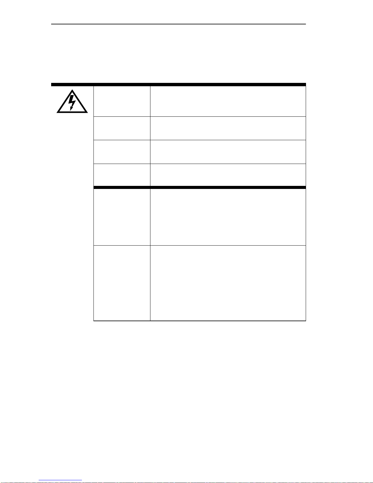
SAFETY REQUIREMENTS
The warnings or cautions tha t must be observed for the hardware
described in this manua l are li sted be low in Engl ish, German, Fre nch, and
Spanish.
W ARNING Only qualified personnel shoul d install thi s unit.
VORSICHT Diese Einheit darf nur von qualifizierten
Fachleuten installiert oder gewartet werde n.
DANGER L'install ation et la mai ntenance de cet appareil
sont réservées à un personnel qualifié.
A VISO Sólo el personal cu alific ado d ebe inst alar o dar
mantenimient o a esta unidad.
W ARNING The DELF3-UI uses Cla ss 1 las ers. Do not use
optical instruments to view the laser output.
The use of optical instruments to view laser
output increases eye hazard. When viewing
the output optic al port, power mus t be remov ed
from the network adapter.
VORSICHT Der DELF3-UI benutzt Lase r der Klasse 1.
Zum Ansehen der Laserausgabe dürfen keine
optischen Gerä te benutzt werden, da dadur ch
das Risiko von Augen verletzungen erhöht
wird. Vor dem Ansehen des optischen
Ausgangsanschlusses muß der
Netzwerkadapter vom Stromans chluß getr ennt
werden.
xviii DLE22-MA, DLE32-MA, DLE23-MA and DLE33-MA User’s Guide
Page 21

Safety Requirements
DANGER DELF3-UI utilise le s lasers de la Classe 1.
N'utilis ez pas d'inst ruments d'opt ique pour voir
la sortie du laser. Leur usage augmente les
risques de lés ions oculaires. Lorsque vous
voyez le port optique de la sortie, vous devez
couper l'ali m entation de l'adaptateur de
réseau.
AVISO DELF3-UI utiliza lásers Clase 1. No utilice
instrument os ópticos para ver la salida de
láser. El uso de instrumentos ópticos para ver
una salida de láser i ncrementa los daños en
los ojos. Al ver el puerto óptico de salida, se
debe retirar l a ali m entación del adapt ador de
red.
DLE22-MA, DLE32-MA, DLE23-MA and DLE33-MA User’s Guide xix
Page 22

Safety
CAUTION
!
CAUTION F ailure to observe static saf ety precauti ons
could cause damage to the DLE22-MA and
DLE23-MA and DLE32-MA and DLE33-MA.
Foll ow static saf ety handl ing rules and properly
wear the antis tati c wrist str ap pro vided with th e
DLM6C-AA chassis.
Do not cut the non-conductive bag to remove
the module. Damage could result from sharp
objects contacting the board or components.
ACHTUNG Eine Nichtbeachtung der
Sicherheitsmaßnahmen hinsichtlich statischer
Entladungen kön nte Schäden am DLE22-MA
unde DLE23-MA und DLE32-MA UND
DLE33-MA verursachen. Folgen Sie deshalb
den Sicherheitsrichtlinien, und tragen Sie das
mit dem DLM6C-AA-Gehäuse gelieferte
Antistatikarmband. Benutz en Sie zum Ö ffnen
der nicht-leitfähigen Plastikhülle, in dem sich
das Modul befind et, keine scharfen
Instrumente, da die Karte oder die
Komponenten beschädigt werden könnten.
ATTENTION Le non respect de consi gnes de sécurité
relative à l'électricité statique peut contribue r à
endommager le DLE22-MA et DLE23-MA et le
DLE32-MA et DLE33-MA. Respec tez ces
consignes lors du transpor t et portez , comme
il convient, le brace let anti-statique four ni avec
le chassis DLM6C- AA. Ne coupez pas le sac
non-isolant, lorsque vous r eti rez le module.
Vous risquez d'endommager la carte et les
composants s'ils sont en contact avec des
objets pointus.
xx DLE22-M A, DLE32-MA, DLE23-MA and DLE33-MA User’s Guide
Page 23

Safety Requirements
PRECAUCIÓN Si no se observan las precauciones de
seguridad est ática, se pueden dañar
DLE22-MA y DLE23-MA y DLE 32-MA y
DLE33-MA. Siga las reglas de transporte de
seguridad estática y utilice de manera
adecuada la banda ant iestática para la
muñeca que se proporciona con el chasis
DLM6C-AA.
No corte la bolsa no conductora para retirar el
módulo. La placa o los componentes podrían
dañarse si hay un cont acto con objetos
agudos.
CAUTION To preve nt damaging the backplane
connectors in the f o ll owing ste p, take care that
the module slides in straight and properly
engages the backplane connectors.
ACHTUNG Um die Anschlüsse an der Rückseite bei
diesem Schritt nicht zu beschädi gen, stellen
Sie sicher, daß das Modul gerade
eingeschoben und vorsichtig eingesetzt wird.
ATTENTION Pour éviter d'endommager les connecteurs du
« backplane » lors de l' étape suiva nte , vei llez à
ce que le module glisse tout droit et s'a dapte
correctemen t aux connecte urs du « backplane
».
PRECAUCIÓN Para evitar dañar los conectores del plano
posterio r en el pas o siguiente, verif ique que el
módulo se desli ce derecho y se adapte
correctamente a los conectores del plano
posterio r.
DLE22-MA, DLE32-MA, DLE23-MA and DLE 33-MA User’s Guide xxi
Page 24

Safety
CAUTION An odd number of crossov ers (pref erably one)
must be maintai ned between de vices so that
the trans mit port of one device is c onnected to
the receive port of the other device and vice
versa.
If the fiber optic ca ble being used has SC style
connectors that do not resemble MIC style
connectors , or has SC connectors on one end
and a different type on the othe r, such as ST
connectors, ensure that the proper crossing
over occurs.
ACHTUNG Eine ungerade Zahl von Über kreuzu ngss tell en
(vorzugsweise eine) muß zwischen den
Geräten beibeh alten werden, damit der
Übertragung sanschluß eines Gerätes mit dem
Empfangsanschluß des anderen Gerätes
verbunden werden kann (und umgekehrt).
Wenn das verwendete Glasfaserkabel
SC-Anschlußst ecker hat, die nicht
MIC-Anschlußsteckern ähnlich sind, oder
wenn es an einem Ende SC-Anschl ußstecker
hat und am anderen Ende einen anderen
Steckerty p (z. B. einen ST-Stecker ),
vergewissern Sie sich, daß di e richtig
Überkreuzung stattfindet.
ATTENTION Un nombre impair de di agonales (de
préférenc e une) doi t être conservé ent re les
périphériques de sorte que le port de
transmiss ion d'un périphérique soit connect é
au port de réception de l'autre péri phérique et
inversement .
Si le cable de fibre optique utilisé est doté de
connecteurs de type SC qui ne ressemblent
pas aux connecteur s de type MIC ou a des
connecteurs de type SC à une extrémité et un
type de connecteur di fférent à l'au tre extrémi té
(comme par exemple des connecteurs de type
ST), assurez-vous que le croisement en
diagonale se fait correctement.
xxii DLE22-MA, DLE32-MA, DLE23-MA and DLE33-MA User’s Guide
Page 25

Safety Requirements
PRECAUCIÓN Un número impar de diagon ales (de
preferenc ia uno) se debe mantener entre los
dispositivos para que el puerto de transmisión
de un dispositivo esté conectado al puerto de
recepción del otro dispositivo y viceversa.
Si el cable de fibra óptica que se está
utilizando tiene conectores de tipo SC que no
se parezcan a conectores de estilo MIC, o
tenga conector es SC en un extremo y un tipo
diferente en el ot ro, como conectores ST,
asegúrese de que se realice el cruce
adecuado.
CAUTION Do not touch the ends of the fiber optic
strands, and do not let the ends come in
contact with dust, dirt, or other contaminants.
Contamination of the ends causes p roblems in
data transmissions. If the ends become
contaminat ed, b lo w the s urf a ces wit h a c anned
duster. A fiber port cleaning swab saturated
with optical- grade isopropyl al cohol may also
be used to clean the ends.
ACHTUNG Das Ende an beiden Seiten des
Glasfaserk abels darf nicht berührt werden
oder mit Staub, Schmutz und anderen Stoffen
in Berührung kommen, die zur Verunreinigung
führen und Datenübertragungsprobleme
verursachen könnten. In einem solchen Fall
müssen die Enden mit einem eigens dazu
bestimmten Sta ubreiniger (z.B. einem
speziellen Staubspray oder ein em in
Isopropylalkohol getaucht en Wattestäbchen)
sorg f äl tig gereinig t w e rd e n.
ATTENTION Ne touchez pas les extrémités des fibr es
optiques et évitez qu'elles viennent en contact
avec des éléments poussiéreux, sales ou tout
autre contami nant. La contaminat ion de ces
extrémit és cause des problèmes lor s de la
transmission des données. Si ces extrémités
sont contamin ées, nettoyez leur surface à
l'aide d'un nettoyant adéquat. Vo us pouvez
également utiliser une éponge imbi bée
d'isopropanol pour les nettoyer.
DLE22-MA, DLE32-MA, DLE23-MA and DLE 33-MA User’s Guide xx iii
Page 26

Safety
PRECAUCIÓN No toque los extremos de las bandas de fibra
óptica y, no permit a que l os c ontact os esté n en
contacto con pol vo, suciedad u otros
contaminantes. La contaminación de los
extremos causa pr oblemas en la transmisión
de datos. Si los extr emos se contaminan,
limpie las superficies con un limpiador
adecuado. Para limpiar el puerto , tambi én se
puede utiliz ar una esp onj a satura da de a lcohol
isopropíli co de grado óptico para l impiar los
extremos.
CAUTION Pressing the RESET button resets the device,
and all current switchi ng being performed by
the devi ce is halted. A module do wntime of up
to two minutes will result from this action.
ACHTUNG Wenn der RESET-Knopf gedrückt wird, wird
das Gerät zurückgestellt und alle vom Gerät
derzeit ausgeführten Schalt ungen werden
gestoppt. Das Gerät ist an schli eßend fü r b is zu
zwei Minuten nicht betriebsbereit.
ATTENTION L'appui sur le bouton RESET réi nitialise
l'appareil , pr ovoq uant l 'arrêt de s c ommutati ons
en cours. L'appareil sera indisponible pendant
deux minutes maximum.
PRECAUCIÓN Al pulsar el botón RESET se reinici a el
dispositivo y se detienen todas las
conmutaciones que en ese momento esté
realizando. El dispositivo no estará disponible
durante un máximo de dos minutos mientras
dura el proceso de reinicio.
CAUTION Before altering the COM port settings, ensure
that a valid IP address is set for the module or
chassis. Read the entire COM port
configuration section before changing the
settings of the COM port.
xxiv DLE22-MA, DLE32-MA, DLE23-MA and DLE33-MA User’s Guide
Page 27

Safety Requirements
ACHTUNG Bevor Sie die Einste ll ungen des COM-Ports
ändern, stellen Sie sicher, daß für das Modul
oder das Gehäuse eine gültige IP-Adresse
eingestellt ist. Lesen Sie den gesamten
Abschnitt zur COM-Port-Konfiguration, bevor
Sie die Einstellungen des COM-Ports ändern .
ATTENTION Avant de modif ier les paramètre s du port
COM, assurez-vou s qu'une adr ess e IP valable
a été att ribuée au module ou au châssis. Lisez
entièrement la sec tion consacrée à la
configur ati on du port COM avant de modifier
ses paramètres.
PRECAUCIÓN Antes de cambiar los parámetros del puerto
COM, asegúrese de haber definido una
dirección de IP válida para el módulo y/o el
chasis. Lea la sección sobre confi guración de
puertos COM en su tot alid ad antes de ca mbiar
ningún parámet ro de un puerto de este tipo.
CAUTION Do NOT disable or alt er the settings of the
COM port while operating the current Local
Management conn ection through a terminal.
Altering the COM port set tings d isconne cts th e
Local Managemen t terminal from the port, and
ends the Local Management session.
ACHTUNG Sie dürfen die COM-Port-Ein stellung en NICHT
abschalten oder ändern, während die aktuelle
LM-Verbindung (Local Management) über ein
Ter m inal besteht. Das Ändern der
COM-Port-Ein stellungen trennt das
LM-Terminal vom Port und beendet die
LM-Sitzung.
ATTENTION NE PAS désactiver ou modif ier les par am ètr es
du port COM pendant la conne xion Local
Management (LM) via un terminal. La
modification des paramètres du port COM
entraîne la déconn exion du termin al LM de son
port, et termine la session LM.
DLE22-MA, DLE32-MA, DLE23-MA and DLE 33-MA User’s Guide xxv
Page 28

Safety
PRECAUCIÓN NO desactive ni cambie los parámetros del
puerto COM mientras esté operando la
conexión actual de gestión local Local
Management (LM) a través de un terminal. Si
lo hace, se desconectará el terminal LM del
puerto, y se term inará la sesión de LM.
CAUTION If the COM port is reconfigured without a valid
IP address set on the mod ule or chassis, the
message sho wn in Fi gure 5-20 displa ys. Do
not continue unless the outcome of t he action
is fully understood.
ACHTUNG Wenn der COM-Port rek onfiguriert wird, ohne
daß auf dem Modul oder dem Gehäu se eine
gültige IP-Adresse eingest ell t ist, wird die in
Abbildung 5-20 gezeigte Meldung angezeigt.
Arbeiten Sie nicht weiter, bevor Sie die
Auswirkungen dieser Aktion vollständig
verstanden hab en.
ATTENTION Si le port COM est reconfiguré sans adresse
IP val able pour le module ou le châssis , le
message de la Figur e 5-20 s' affiche . Ne continuez pas sans avoir bien compris les conséquences de votre action.
PRECAUCIÓN Si se reconfigura el puerto COM sin haber
definido una dirección de IP válida en el
módulo o el chasis, aparecerá el mensaj e
mostrado en la Figura 5-20. No continúe a no
ser que entienda perfectamente las
consecuencias de esta acción.
CAUTION Exiting without saving causes the message
“NOT SAVED -- PRESS SAVE TO KEEP
CHANGES” to appear. Exiting wi thout saving
causes all edits to be lost.
ACHTUNG Beenden ohne Speicher n verursacht die
Meldung "NOT SAVED -- PRESS SAVE TO
KEEP CHANGES" (Nicht gespeichert Drücken Sie Save/S peichern, um die
Änderungen zu speichern). Durch Beenden
ohne Speichern geh en alle durchgeführ ten
Änderungen verloren.
xxvi DLE22-MA, DLE32-MA, DLE23-MA and DLE33-MA User’s Guide
Page 29
Safety Requirements
ATTENTION Si vous sortez sans enregistrer, le message
"NOT SAVED - PRESS SAVE TO KEEP
CHANGES" (Non enregistré - Appuyez sur
SAVE pour conserver l es m odifications)
s'affiche. Toutes vos modificati ons seront
perdues.
PRECAUCIÓN Si sale sin guardar, aparece rá el mensaje
"NOT SAVED -- PRESS SAVE TO KEEP
CHANGES" (NO SE HA GUARDADO PULSE GUARDAR PARA CONSER VAR LOS
CAMBIOS). Si sale sin guardar se perderán
todos los cambios.
CAUTION When the COM port is configured to perform
the UPS application, al l future Local
Management connections must be made by
establ ishin g a Telnet conn ect ion to the m odule .
Ensure that the module has a valid IP address
before saving changes to the COM port
applicatio n. If the mo dule does not ha v e a val id
IP address and the chang es are sa ved, refer t o
Appendix C f or instructions on cle aring
NVRAM in order to reestab lish COM port
communications.
ACHTUNG Wenn der COM-Port für die Ausführung der
UPS-Anwendung konfiguriert ist, müssen alle
zukünftigen Local-Ma nagem ent-Verbindungen
durchgeführ t wer den, indem eine
Telnet-Verbindung zum Modul aufgebaut wird.
Stellen Sie sic her, daß das M odul eine gültige
IP-Adresse hat, bevor Sie Änderungen in der
COM-Port-Anwendung speichern. W enn das
Modul keine gültige IP-Adresse hat und die
Änderungen gespe ichert wur den, finden Sie i m
Anhang C Anleitungen zum Löschen des
NVRAM, um die COM-Port-Kommuni kationen
wiederherzustellen.
DLE22-MA, DLE32-MA, DLE23-MA and DLE 33-MA User’s Guide xxvii
Page 30

Safety
ATTENTION Lorsque le port COM est configuré pour une
application UPS, toute future connexion Local
Management doit se f aire en établissant une
connexion Telnet au module. Assurez-vous
que celui-ci possède une adresse IP val able
avant d'e nregis trer les modi fic ations appo rtées
au port COM. Si le module n'es t pas doté
d'une adresse IP valable et que les
modificat ions sont enregistrées, reportez-vous
à l'Annexe C pour apprendre comment
initialiser la NVRAM avant de rétablir des
communications COM.
PRECAUCIÓN Cuando el puerto COM está co nfi gurado para
la aplicación UPS, todas las conexiones de
gestión local (LM, Local Management)
deberán realizarse establec iendo una
conexión Telnet con el módulo. Asegúrese de
que el módulo tiene una dirección de IP válida
antes de guardar los camb ios en la aplica ción
del puerto COM. Si el módulo no tie ne una
dirección de IP válida y se han guardado los
cambios, consulte el Apendice C para obtener
instrucciones sobre el borr ado del contenido
de la memoria NVRAM para restablecer las
comunicaciones del puerto COM.
CAUTION Clearing NVRAM will result in the loss of all
user-ente red parameters. Do not proceed
unless this procedure is completely
understood.
ACHTUNG Das Löschen des NVRAM führt zum Verlus t
aller vom Benutzer eingegebenen Parameter.
Arbeiten Sie nicht weiter, bevor Sie dieses
Verfahren voll ständig versta nden haben.
ATTENTION Si vous réinitialisez la NVRAM, tous les
paramètres ut il isateur seron t perdus.
N'exécutez donc cette procédure qu'en
parfaite connaissance de cause.
PRECAUCIÓN El borrado del contenido de la memoria
NVRAM provocará la pérdida de todos los
parámetros i ntr oducidos por el usuario. No
continúe a no ser que comp renda totalmente
este procedim iento.
xxviiiDLE22-MA, DLE32-MA, DLE23-MA and DLE33-MA User’s Guide
Page 31

Safety Requirements
CAUTION If the DLE2X-MA and DLE3X-MA are being
bridged to an FDDI ring (for example, via an
DELHF-UA installed in the DLE3X-M A) IP
Fragmentation should be enabled. If IP
Fr agmentat ion is disabl ed, all FDDI fra mes that
exceed the maximum Ethernet frame size will
be discarded.
ACHTUNG Wenn DLE2X-MA und DLE3X-MA per Bridge
an einen FDDI-Ring angeschlossen werden
(Beispiel: über ei nen DELHF-UA, der im
DLE3X-MA installiert ist), sollte
IP-Fragmentierung aktiviert werden. Wenn
IP-Fragment ierung deaktiviert wird, werden
alle FDDI-Frames, die die maximale
Ethernet-Frame-Größe überschreiten,
verworfen.
ATTENTION Si les appareils DLE2X- MA et DLE3X-MA sont
reliés (pontage) sur un anneau FDDI (par
exemple, via un DELHF-UA installé sur le
DLE3X-MA), la fragmentation IP doit être
active. Dans le ca s con trai re, to utes l es f rames
FDDI dépassant la taille maximum des frames
Ethernet seront ignorées.
PRECAUCIÓN Si los DLE2X-MA y DLE3X-MA se están
puenteando a un anillo FDDI (por ejemplo a
través de un DELHF-UA instalado en el
DLE3X-MA), la fragmentación de IP (IP
Fragmentation) deberá estar activada. Si está
desactivada todos los marcos FDDI que
superen el tamaño máxim o de ma rco de
Ethernet se dese charán.
CAUTION The Network Tools connecti on to the module
will be terminated upon execution of this
command.
ACHTUNG Die Network Tools-V e rbindu ng z um Modu l wir d
bei der Ausführung dieses Befehls beendet.
ATTENTION La connexion Networ k Tools au module
PRECAUCIÓN La conexión de Networ k Tools con el módulo
DLE22-MA, DLE32-MA, DLE23-MA and DLE 33-MA User’s Guide xx ix
cessera à l'exécution de cette commande.
se terminará al ej ecutar este comando.
Page 32

Safety
CAUTION The Fast Ethernet Interface Module and the
host module are sensitive to static discharges.
Use an antistati c wrist str ap and observe all
static precautions during this procedure.
Failure to do so could damage the Fast
Ethernet Interface Module or t he host module.
ACHTUNG Das schnelle Etherne t-Schnittstell enmodul und
das Hostsystemmodul sind für statische
Entladungen empf indlich. Benutzen Sie
deshalb ein Antistatikarmband, und beachten
Sie während dieses Verf ahrens alle
diesbezügl ichen V orsichtsmaßnahmen. Bei
Nichtbeachtung könnte das schnelle
Ethernet-Schnittstel lenmodul oder das
Hostsystemmodul beschädigt werden.
ATTENTION Le module d'interface Fast Ethernet et le
module 'hôte' sont sensibles aux décharges
statiques. Utilisez un bracelet antistatique et
prenez toutes les précautions nécessaires
durant la procédure. Dans le cas contraire,
vous risquez d'endommager le module
d'interfa ce Fast Ethernet ou le modul e ' hôte'
PRECAUCIÓN Fast Ethernet Interface Module y el módulo
host son sensibles a las descarg as estáticas.
Utilice una banda antiestática para el puño y
observe todas las precaucion e s de estática
durante este procedimiento. Si no lo hace,
podría dañar Fast Ethernet Interface Module o
el módulo host.
CAUTION When installing an DELFX-UI or DELF3-UI
module into the host module, remove the
rubber plug on the SC connector before
proceeding.
ACHTUNG Vor der Installation eines DELFX-UI- oder
DELF3-UI-Moduls in das Hostsystemmodul
muß der Gummistöpsel vom
SC-Anschlußstecker entfernt werden.
ATTENTION Lorsque vous instal lez un module DELFX-UI
ou un module DELF3-UI, retirez la prise en
caoutchouc pl acée sur le conne cte ur SC avant
de procéder à l'installation.
xxx DL E 22-M A, DLE32-MA, DLE23-MA and DLE33-M A User’s Guide
Page 33

Safety Requirements
PRECAUCIÓN Al instalar un módulo DELFX-UI o DELF3-UI
en el módulo de host, retire el enchufe de
caucho del conect or SC antes de continuar.
CAUTION When inserting the Fast Ethernet Interface
Module into the m otherboar d connector en sure
that the pins do not bend, as thi s can damage
both the Fast Ethernet Inter face Module and
the motherboard connector.
ACHTUNG Beachten Sie, daß das schnelle
Ethernet-Schnittstel lenmodul gerade in die
Hauptplatine eingesetzt wird und die Nadeln
nicht gebogen werden. Wird es schräg
eingesetzt, könnten sowohl das schnelle
Ethernet-Schnittstel lenmodul als auch di e
Hauptplatine beschädigt werde n.
ATTENTION Lorsque vous ins érez le module d'interface
Fast Ethernet dans le connecteur de de la
carte mère, assurez-vous que l es broches ne
sont pas pliée s, car vous risquez
d'endommager à la f ois le module et le
connecteur.
PRECAUCIÓN Al insertar Fast Ethernet Interfac e Mod ule en
el conector de la pla ca base, asegúrese de
que las patill as no se doblen, ya que esto
podría dañar tanto Fast Ethernet Interface
Module, como el conector de la placa base.
DLE22-MA, DLE32-MA, DLE23-MA and DLE 33-MA User’s Guide xx xi
Page 34

Page 35

CHAPTER 1
INTRODUCTION
This chapter describ es the features of the DLE2X-MA and DLE3X-MA
Interface Modules.
1.1 DLE2X-MA AND DLE3X-MA OVERVIEW
The DLE2X-MA and DLE3X-MA, shown in Figure 1-1, are interface
modules for the DLM6C-AA chassis.
The DLE2X-MA and DLE3X-MA are high-speed network switch
devices that support 802.1D switching (bridging) and 802.1Q switching.
Ports 25 and 26 of the DLE2X-MA support optional Fast Ethernet
Interface Modules and can provide uplinks to 100BASE-TX or
100BASE-FX Fast Ethernet netw orks. The DLE3X-MA is capable of
being equipped with a High Speed Interface Module (HSIM) that
provides for addi tional connectivity to other high speed net working
technologies such as Asychr onous Transfer Mode (ATM), Wide Area
Networks (WANs) and Fiber Distributed Data Interface (FDDI).
The DLM6C-AA can be used to connect individual high-bandwidth user
devices, such as workstations, and t o provide a central switching point for
multiple Ethernet segments using devices such as the HubSTACK or
other third party stac kable devices.
Figure 1-1 displays the DLE22-MA and DLE32-MA. The
DLE22-MA and the DLE23-MA are functionally identical, as are
the DLE32-MA and the DLE33-MA. The only difference being
that the DLE23-MA and DLE33-MA modules support RJ21
front panel connections.
DLE22-MA, DLE32-MA, DLE23-MA and DLE 33-MA User’s Guide 1-1
Page 36

Chapter 1: Introduction
Network
Ports 1-24
Ethernet
DLE22-MA
CPU
COM
12
34
56
78
910
11 12
15 16
17 18
19 20
1413
COM Ports
System
LEDs
Port Status
LEDs
Ethernet
DLE32-MA
CPU
COM
12
34
56
78
910
11 12
15 16
17 18
19 20
Network
Ports 1-24
1413
Fast Ethernet
Interface Module
Ports 25 and 26
21 22
23 24
25
21 22
23 24
HSIM Slot
26
Figure 1-1 The DLE22-MA and DLE32-MA
1-2 DLE22-MA, DLE32-MA, DLE23-MA an d DLE33-MA User’s Guide
LKG-10877-98F
Page 37

DLE2X-MA a nd DLE3X-MA Ove rvi ew
1.1.1 Connectivity
The DLE22-MA and DLE32-MA connect to Ethernet networks or
workstations through 24 RJ45 ports on the front panel. These port s
support UTP connections up to 100 meters. The ports a re IEEE 802. 3
10BASE-T compliant.
The DLE23-MA and DLE33-MA connect to Ethernet networks or
workstations through two RJ21 connectors on the front pa ne l. The se
connectors support 25 pair cable at lengths up to 100 meters. The ports
are IEEE 802.3 10BASE-T compliant.
The DLE2X-MA modules hav e two f ront pa nel slots (ports 25 and 26) for
optional Fast Ethernet Interface Modules to support an uplink to
100 Mbps Ethernet backbones or a high speed connection to a local
server.
The DLE3X-MA modules have one front panel slot for an optional High
Speed In te rface Module to provide for additional connectivi ty to other
high speed networking technologies such as ATM, WANs and FDDI.
1.1.2 Full Duplex Switched Ethernet
Each switched Ethernet port supports full wire-speed Ethernet
communications and can be configured to operate in Full Duplex
Switched Ethernet mode, which provides up to 20 Mbps of bandwidth.
The optional Fast Ethernet Interface Modules for the DLE2X-MA can
also be configur ed to operate in Full Duplex Switche d Ethernet mode,
which provides up to 200 Mbps of bandwidth.
1.1.3 SmartTr un k
The SmartT runk f eature a llo ws the user to se t a gr oup of DLE2X-MA and
DLE3X-MA interfaces, so they can share the traffic load an d effectively
increase the bandwidth between connected DLE2X-MA and
DLE3X-MAs or other devic es supporting the SmartTrunk feature . For
example, Ports 25 a nd 26 of the DLE2X-MA could be grouped to provide
a 200-Mbps uplink.
DLE22-MA, DLE32-MA, DLE23-MA and DLE 33-MA User’s Guide 1-3
Page 38

Chapter 1: Introduction
1.1.4 Management
Management of the DLE2X-MA and DLE3X-MA is accomplis hed using
Local Management tools or remote SNMP management sta tions. Local
Management is accessible through the RS232 COM port on the front
panel using a local VT100 terminal, or a remote VT100 terminal via a
modem connection, and in-ba nd via a Telnet connection. In-band remote
management is possible through any SNMP compliant Network
Management Soft ware.
1.1.5 Switching Options
The DLE2X-MA and DLE3X-MA pro vide 802. 1D switchin g and 802. 1Q
switching between a ll of the f ront pa nel int erfaces including Fast Ethernet
Interface Modules and High Speed Interface Modules (HSIMs).
The 802.1Q switching option allows for future migration to Virtual
Network technologie s without requiring the repl acement of existing
equipment.
1.1.6 Standards Compatibility
The DLE2X-MA and DLE3X-MA are fully compliant with the IEEE
802.3 standard. The optional Fast Ethernet Interface Modules are fully
compliant with the IEEE 802.3u standard. The DLE2X-MA and
DLE3X-MA provide IEEE 802.1D Spanning Tree Algorithm (STA)
support to enhance the overall relia bility of the network and protec t
against “loop” condi tions. The DLE2X-MA and DLE3X-MA support a
wide variety of industry standard MIBs including RFC 1213 (MIB II),
RFC 1757 (RMON), RFC 1493 (Bridge MIB) and RFC 1354 (FIB MIB).
A full suite of the Enterprise MIBs provide a wide array of statistical
information to enhance troubleshooting.
1.1.7 LANVIEW Diagnostic LEDs
LANVIEW diagnostic LEDs serve as a n importa nt t roubleshoot ing aid b y
providing an easy w ay to obse rv e the s tatus of ind i vi dual ports a nd o ve rall
network ope rati ons. C hapter 4 provi des de tails about the DLE2X-MA and
DLE3X-MA LANVIEW LEDs.
1-4 DLE22-MA, DLE32-MA, DLE23-MA an d DLE33-MA User’s Guide
Page 39

DLE2X-MA a nd DLE3X-MA Ove rvi ew
1.1.8 Year 2000 Compliant
The DLE2X-MA and DLE3X-MA have an internal clock that can
maintain the current time and date be yond the year 1999.
1.1.9 Runtime IP Address Discovery
This feature enables the modules to automatically accept an IP address
from a BootP server on the networ k into NVRAM without requiring a
user to enter an IP address through Local Mana geme nt.
When the modules are connected to the netw ork and powered up,
Runtime IP Address Discovery (RAD) checks the modules for an IP
address. If one has not yet been assigned (module and DLM6C-AA
chassis IP addre ss set to 0.0.0.0), RAD checks to se e if any of the module
interfaces have a link. If so, RAD sends out Reverse Address Resolution
Protocol (RARP) and BootP requests to obta in an IP address from a
RARP or BootP server on the network.
The RAD requests start out a t an interval of one second. The interval then
doubles after every trans mission until an interval of 300 seconds is
reached. At this point, the interval remains at 300 seconds. The RAD
requests continue until an IP address is received from a RARP or BootP
server, or an IP address is entere d using Local Management.
1.1.10 Local Management Features
Local Management provides the tools that allow management of the
DLE2X-MA and DLE3X-MA, the Fast Ethernet Interface Modules, the
High Speed Interface Module (HSIM) and the DLM6C-AA chassis. It
also allows the following tasks to be performed:
• Manage any module insta lled in the DLM6C-AA via a s ingle termina l
connection.
• Assign an IP address and subnet mask to the DLM6C-AA chassis,
DLE2X-MA and DLE3X-MA.
• Select a default gateway.
• Control local and remote access.
DLE22-MA, DLE32-MA, DLE23-MA and DLE 33-MA User’s Guide 1-5
Page 40

Chapter 1: Introduction
• Designate workstations to receive SNMP tra ps from the DLE2X-MA
and DLE3X-MA interface modules and the DLM6C-AA chassis.
• Configure module specific SNMP MIB objects including the IETF
Bridge MIB objects.
Chapter 5 provides detailed information about Local Management of the
DLE2X-MA and DLE3X-MA, the optional Fast Ethernet Interface
Modules and the DLM6C-AA chassis. The associated High Speed
Interface Module user’s guide provides detailed information about Local
Management of the applicable HSIM.
1.2 OPTIONAL FEATURES
Options for the DLE2X-MA and DLE3X-MA are Fast Ethernet Interface
Modules and High Speed Interface Modules, which add remote uplink
capability.
Digital Equipment Corporation provides Fast Ethernet Interface Modules
for the DLE2X-MA to support uplinks to 100 Mbps Ethernet backbones
or high speed connections to loc al ser vers. The Fast Ethe rnet Interface
Modules are listed in Table 1-1.
Table 1-1 Fast Ethernet Interface Modules
P/N Description Applicati on
Supports Shielded Twisted Pair (STP) and
Category 5 Unshielded Twisted Pair (UTP)
cabling.
Supports multimode fiber optic cabling.
Supports single mode fibe r optic cabling.
DELTX-UI
DELFX-UI
DELF3-UI
Uses RJ45
connector
Uses SC
connector
Uses SC
connector
Digital Equipment Corpora tion provides High Speed Interface Modules
for the DLE3X-MA to provide for additional connectivity to other high
speed networking te chnologies such as ATM, WANs and FDDI. The
HSIMs available for the DLE3X-MA are listed in the Releas e Notes.
1-6 DLE22-MA, DLE32-MA, DLE23-MA an d DLE33-MA User’s Guide
Page 41

CHAPTER 2
NET WORK REQUIREMENTS
Before installing the DLE2X-MA and DLE3X-MA or Fast Ethe rnet
Interface Modules (DELTX-UI, DELFX-UI, or DELF3-UI), review the
requirements and specifications referred to in this chap ter co n cer ning the
following:
• SmartTrunk (Section 2.1)
• 10BASE-T Twisted P air Network (Section 2.2)
• 100BASE-TX Twisted Pair Network (Section 2.3)
• 100BASE-FX Fiber Optic Network (Sectio n 2.4)
The network installation must meet the guidelines to ensure satisfactory
performance of this equipment. Failure to foll ow the guidelines may
produce poor network perf ormance.
The Cabletron Systems Cabling Guide, referred to in the
DIGITAL Wo rld Wide Web site:
http://www.networks.digital.com
2.1 SmartTrunk
To connect the DLE2X-MA and DLE3X-MA to a network so the y can
take advantage of the SmartTrunk feature, ther e are cer tain rules
concerning port connections and configurations that must b e followed for
proper operation. Section 5.20.1, SmartTrunk Configuration Rules in
describes SmartTrunking and provides the conf igur ation rules.
DLE22-MA, DLE32-MA, DLE23-MA and DLE 33-MA User’s Guide 2-1
Page 42

Chapter 2: Network Requirements
2.2 10BASE-T NETWORK
When connecting a 10BAS E-T segment to any of the DLE2X-MA and
DLE3X-MA ports (Interfaces 1 through 24), ensure that the network
meets the Ethernet networ k requirements of the IEEE 802.3 standard for
10BASE-T. Refer to the Cabletron Systems Cabling Guide for details.
2.3 100BASE-TX NETWORK
The DLE2X-MA, with an DELTX-UI install ed in ports 25 and 26,
provides a n RJ45 conn ection tha t support s UTP cabling . The de vic e at the
other end of the twisted pair segment must meet IEEE 802.3u
100BASE-TX Fast Ethernet network requirements for the devices to
operate at 100 Mbps. Refer to the Cabletron Systems Cabling Guide for
details.
The DLE2X-MA with an DELTX-UI installed is capable of
operating at either 10 or 100 Mbps. The DELTX-UI can
automatically sense the speed of the other device and adjusts
its speed accordingly.
2.4 100BASE-FX FIBER OPTIC NETWORK
Ports 25 and 26 of the DLE2X-MA support the DELFX-UI and
DELF3-UI fiber optic interface modules. The device at the other end of
the fiber optic segment must meet the 100BASE-FX Fast Ethernet
network requirements to operate at 100 Mbps. Refer to the Cabletron
Systems Cabling Guide for details.
Multimode Mode Fiber Optic Cable Length
The maximum multimode fiber optic cable length of a 100BAS E-FX
segment is covered in the Cabletr on Systems Cabling Guide.
Single Mode Fiber Cable Lengths
The maximum single mode f iber optic length of a 100BASE-FX se gment
may be no more than 5 km between Data Terminal Equipment (DTE to
DTE) in half duplex mode or 20 km (DTE to DTE) in full duplex mode.
2-2 DLE22-MA, DLE32-MA, DLE23-MA an d DLE33-MA User’s Guide
Page 43

CHAPTER 3
INSTALLATION
Only qualified personnel should install the DLE2X-MA and
DLE3X-MA.
This chapter cov ers the following items:
• Required tools
• Unpacking the DLE2X-MA and DLE3X-MA
• Installing the DLE2X-MA and DLE3X-MA into the DLM6C-AA
chassis
• Connecting to the network
3.1 REQUIRED TOOLS
A Phillips screwdr iver is required to install the optional Fast Ethernet
Interface Modules into the DLE2X-MA.
3.2 UNPACKING THE DLE2X-MA AND DLE3X-MA
1. Open the box and remove the packing mate rial protecting the module.
2. Verify the contents of the carton as listed in Table 3-1.
Table 3-1 Contents of Shipping Carton
Item Quantity
DLE32-MA, DLE22-MA,
DLE33-MA or
DLE23-MA
Release Notes 1
1
DLE22-MA, DLE32-MA, DLE23-MA and DLE 33-MA User’s Guide 3-1
RJ21 Angle Adapter
(DLE23-MA and
DLE33-MA only)
2
Page 44

Chapter 3: Installation
3.3 DLE2X-MA AND DLE3X-MA OPTIONS
Install any optional equipment before proceeding to
Section 3.4.
If the DLE2X-MA is to be installed with an optional F a st Ethernet
Interface Module, refer to Appendix C for installation instr uctions. The
installation instructions for the HSIMs available for the DLE3X-MA are
located in the associat ed user ’s guide.
3.4 INSTALLING THE DLE2X-MA AND DLE3X-MA
INTO THE DLM6C-AA CHASSIS
Failure to obser ve static safety precautions could cause
!
!
damage to the DLE2X-MA and DLE3X-MA. Follow static safety
handling rules and proper ly wear the antistatic wrist strap
provided with the DLM6C-AA chassis.
Do not cut the non-conductive bag to remove the module.
Damage could result from shar p object s contact ing the board
or components.
The DLE2X-MA and DLE3X-MA can be installed in any of the 5 slots
that are av ailable. To install a module, proceed as follows:
1. Remove the blank panel coveri ng the sl ot in which the module will be
installed. All other sl ots must r emain covere d to e nsure proper air flow
and cooling. (Save the bl ank pla te i n the e vent you need t o r emove t he
module.)
2. Carefully remove the module from the shipping box. (Save the box
and packing materials in the event the module must be reshipped.)
3. Locate the antistatic wri st strap shipped wit h the DLM6C-AA chassis.
Attach the strap to your wrist and plug the cable from the antistatic
wrist strap into the ESD grounding receptac le at the upper ri ght corner
of the DLM6C-AA.
3-2 DLE22-MA, DLE32-MA, DLE23-MA an d DLE33-MA User’s Guide
Page 45

Installing the DLE2X-MA and DLE3X-MA Into the DLM6C-AA Chassis
4. Remove the module from the plastic bag. (Save the bag in the event
the module must be reshipped.) Observe all precautions to prevent
damage from Electrostatic Discharge (ESD).
5. Examine the module for damage. If any damage exists, DO NOT
install the module. Immediately contact your DIGITAL
representative.
To prevent damaging the backplane connectors in the f ollo wing
!
step, take care that the module slides in straight and properly
engages the backplane connectors.
In the following step, ensure that the top plastic locking tab
lines up with the desired slot number located on the front panel
of the chassis. Refer to Figure 3-1.
6. Locate the slot guides that line up with the number of the slot in whic h
the module will be installed. Install the module in the chassis by
aligning the module circuit card between the upper and lower metal
rail guides of the desired slot, sliding it into the chassi s, a nd locking
down the top and bottom plastic locki ng tabs, a s shown in Figure 3-1.
Take care that the module slides in straight and properly engages the
backplane connectors.
DLE22-MA, DLE32-MA, DLE23-MA and DLE 33-MA User’s Guide 3-3
Page 46

Chapter 3: Installation
Slot Number
Plastic Locking Tab
TM
1
2
MultiSwitch 700
3
45
Fast Enet
6E162-25
PS1
COM
CPU
12
34
56
HA205-AA
78
910
11 12
1413
15 16
17 18
19 20
21 22
23 24
25
DLM6C-AA
PS2
TM
TM
HA205-AA
LKG-10876-98F
Metal Back-Panel
Figure 3-1 Installing an Interface Module
3-4 DLE22-MA, DLE32-MA, DLE23-MA an d DLE33-MA User’s Guide
Circuit Card
Card Guides
H3105-AA
TM
Plastic Locking Tab
Page 47

Connecting to the Network
3.5 CONNECTING TO THE NETWORK
This section provides the procedures for conne ct ing segments from the
network or other devices to the modules.
If the DLE2X-MA and DLE3X-MA are being installed in a
network using SmartTrunk in g, there are rules concerning the
network cable and port configurations that must be followed for
SmartTrunking to operate properly. Before connecting the
cables refer t o Section 5.20.1, SmartTrunk Configuration Rules,
for the configuration information.
Ports 1 through 24 on the DLE22-MA and DLE32-MA have RJ45
connectors for twisted pair connections. Ports 1 through 24 on the
DLE23-MA and DLE33-MA have RJ21 connect ors for twisted pair
connections. Ports 25 and 26 of the DLE2X-MA support DELTX-UI,
DELFX-UI, or DELF3-UI Fast Ethernet Interface Modules. The
DELTX-UI has an RJ45 connector for a Twisted Pair cable connect ion.
The DELFX-UI has an SC style connector for a multimode fiber optic
cable connection. The DELF3-UI has an SC style conn ector for a single
mode fiber optic cable connection.
Refer to Section 3.5.1 to make twisted pair connections to ports 1 through
24 of the DLE22-MA and DLE32-MA.
Refer to Section 3.5.2 to make twisted pair connections to ports 1 through
24 of the DLE23-MA and DLE33-MA.
Refer to Section 3.5.3 to make a Twisted Pair connectio n to an
DELTX-UI.
Refer to Section 3.5.4 to make a fiber opti c connection to an DELFX-UI
or DELF3-UI.
DLE22-MA, DLE32-MA, DLE23-MA and DLE 33-MA User’s Guide 3-5
Page 48

Chapter 3: Installation
3.5.1 Connectin g U T P Cab le s to Ports 1 Throug h 24 o f
the DLE22-MA and DLE32-MA
Ports 1 through 24 of the DLE22-MA and DLE32-MA are 10BASE-T
ports with internal crossover s. Whe n connecting a workstation , use a
straight-through cable. When connecting networking devices, such as
another bridge, repeate r, or router, use a crossover cable.
Connect a twisted pair segm ent to the DLE22-MA and DLE32-MA as
follows:
1. Ensure that the device connected to the other end of the segment is
powered ON.
2. Connect the twisted pair se gment to the DLE32-MA or DLE22-MA by
inserting the RJ45 connector on the twisted pair segment into the
desired RJ45 port (Ports 1 through 24) as shown in Figure 3-2.
.
56
78
910
11 12
1413
15 16
RX (Receive)
LED
17 18
19 20
21 22
23 24
Figure 3-2 DLE22-MA and DLE32-MA Twist ed Pair Connection
3-6 DLE22-MA, DLE32-MA, DLE23-MA an d DLE33-MA User’s Guide
LKG-10954-98F
Page 49

Connecting to the Network
3. Verify that a link exists by checking that the port RX LED is on
(flashing amber , blinki ng green, or sol id gr een). If the RX LED is off,
perform the following steps until it is on:
a. Verify that the 10BASE-T device at the other end of the twisted
pair segment is ON and connected to the segment.
b. Verify t hat the RJ45 connect ors on the twisted pair segment ha ve
the proper pinouts ( Figure 3-3) and check th e cable for co ntinuity.
NOTE:
RX+/RX– and TX+/TX–
must share a common
color pair.
TO
SmartSwitch RJ45 Port
RX+
RX– 2
TX+
TX–
1
3
6
10BASE-T Device Port
RJ45 to RJ45
TO
RX+
1
RX–
2
TX+
3
TX–
6
LKG-10875-98F
Figure 3-3 Cable Pinouts - (RJ45) Crossover Cable
c. Check that the twisted pa ir connection meets t he dB loss an d cable
specificati ons outlined in Chapter 2.
If a link is not established, contact your DIGITAL representative.
4. Repeat steps 1 thr ough 3, above , unti l a ll c onnec tions ha ve be en made.
DLE22-MA, DLE32-MA, DLE23-MA and DLE 33-MA User’s Guide 3-7
Page 50

Chapter 3: Installation
3.5.2 Connectin g U T P Cab le s to Ports 1 Throug h 24 o f
the DLE33-MA and DLE23-MA
When facing the front panel of the DLE33-MA or DLE23-MA, the uppe r
RJ21 is the connector for 10BASE-T ports 1 through 12. The lower RJ21
is for 10BASE-T ports 13 through 24. All 24 ports have internal
crossovers.
Connect a twisted pair segm ent to the DLE33-MA and DLE23-MA as
follows:
1. Ensure that the device connected to the other end of the segment is
powered ON.
2. If using an RJ21 straight connector, plug it into the appropriate RJ21
port as shown in Figure 3-4 or, if using the RJ21 angle adapter
supplied with the device, insert the RJ21 angle adapter as shown in
Figure 3-5. The RJ21 angle adapter allows the cable to be inserted
without interfering with the proper at tachment of the second
connector.
.
Screw Hole
910
11 12
Screw
1
1413
24
15 16
RX (Receive)
LED
17 18
19 20
21 22
23 24
13
LKG-10874-98F
Screw
Screw Hole
Figure 3-4 DLE33-MA and DLE23-MA Twist ed Pair Connection
3-8 DLE22-MA, DLE32-MA, DLE23-MA an d DLE33-MA User’s Guide
Page 51

Connecting to the Network
910
Screw
Screw
Screw Hole
Screw Hole
11 12
1413
15 16
RX (Receive)
LED
17 18
19 20
21 22
23 24
LKG-10873-98F
Figure 3-5 Connection Using the RJ21 Angle Adapter
3. Tighten the two screws on the RJ21 connector or RJ21 angle adapter,
as applicable, to secure it to the module.
The cable pinouts for a 25 pair cable (RJ21) can be found in
the Cabletron Systems
Documentation
, for details on how to obtain this document.
Cabling Guide
. Refer to
Related
4. If using the RJ21 angle adapter, plug the 25 pa ir ca ble int o the a dapte r
as shown in Figure 3-5.
5. Verify that a link exists by checking that the port RX LEDs are on
(flashing amber, blinking green, or solid green). I f the RX LEDs are
off, perform the following steps until it is on:
a. Verify that the 10BASE-T device at the other end of the twisted
pair segment is ON and connected to the segment.
DLE22-MA, DLE32-MA, DLE23-MA and DLE 33-MA User’s Guide 3-9
Page 52

Chapter 3: Installation
b. Verify t hat the RJ21 connect ors on the twisted pair segment ha ve
the proper pinouts and check the cable for continuity.
c. Check that the twisted pa ir connection meets t he dB loss an d cable
specificati ons outlined in Chapter 2.
If a link is not established, contact your DIGITAL representative.
6. Repeat steps 1 thr ough 4, above , unti l a ll c onnec tions ha ve be en made.
3.5.3 Connecting a Twisted Pair Segment to the
DELTX-UI
An DELTX-UI installed in port 25 and/or 26 has an internal crossover
switch. When connecting a workstation, use a straight-through cable and
set the Fast Eth ern et In te rface Mo dule crossover switch shown in
Figure 3-6 to the crossed over posi tion marked with X. When connecting
networking devices, such as another bridge, repeater, or router, use a
straight-through cable and set the Fast Ether net Interface Module
crossover switch shown in Figure 3-6 to the not crossed over position,
marked with =.
A schematic of a crossover cable is shown in Figure 3-6. If the wires do
not cross ove r, use the switch on the DELTX-UI to internally cross ov er
the RJ45 port. Figure 3-6 shows how to properly set the DELTX-UI
crossover switch.
3-10 DLE22-MA , DLE32-MA, DLE23-MA an d DLE33-MA User’s Guide
Page 53

Connecting to the Network
Position =
(not crossed over)
1. TX+
2. TX-
3. RX+
4. NC
5. NC
6. RX-
7. NC
8. NC
Figure 3-6 DELTX-UI Crossover Switch
=
DELTX-UI
x
10
100
Position X
(crossed over)
1. RX+
2. RX-
3. TX+
4. NC
5. NC
6. TX-
7. NC
8. NC
LKG-10872-98F
Connect an DELTX-UI to a twisted pair segment as follows:
1. Ensure that the device connected to the other end of the segment is
powered ON.
2. Connect the twisted pair segment to the module by inserting the RJ45
connector on the twisted pair seg ment into the RJ45 port on the
module shown in Figure 3-6.
3. V erify that a link exists by checking that the port RX LED is on
(flashing amber, blinking green, or soli d gr een). If the RX LED is of f,
perform the following steps until it is on:
a. V er ify that the 100B ASE-TX de vice a t the other en d of the twisted
pair segment is po wered up.
b. Verify th at the RJ45 connector on the twis ted pair se gment has the
proper pinouts.
c. Check the cable for continuity.
d. Make sure that the t wisted pair connection mee ts dB loss and cable
specifications outlined in Section 2.3.
e. Confirm that the crossover switc h is in the correct position.
If a link is not established, contact your DIGITAL representative.
DLE22-MA, DLE32-MA, DLE23-MA and DLE 33-MA User’s Guide 3-11
Page 54

Chapter 3: Installation
3.5.4 Connecting a Fiber Optic Segment
to the DELFX-UI and DELF3-UI
The DELFX-UI and DELF3-UI have an SC style net wor k port (see
Figure 3-7). Cabletron Systems suppli es fiber optic cable that uses SC
style connectors that are keyed to ensure proper crossing over of the
transmit and receive fibers.
An odd number of crossovers (preferably one) must be
!
maintained between devices so that the transmit port of one
device is connected to the receive port of the other device and
vice versa.
If the fiber optic cable being used has SC style connectors that
do not resemble MIC style connectors, or has SC connectors
on one end and a diff erent type on the other , such as ST
connectors, ensure that the proper crossing ov er occurs.
Fiber Optic Network Connection
1. Remove the protective plastic covers from the fiber optic por ts on the
applicable port on the module and fr om the ends of the conne ctors.
The DELF3-UI uses Class 1 lasers. Do not use optical
instruments to view the laser output. The use of optical
instruments to view laser output increases eye hazard. When
viewing the output optical port, power must be removed from
the network adapter.
Do not touch the ends of the fiber optic strands, and do not let
!
the ends come in contact with dust, dirt, or other contaminants.
Contamination of the ends causes problems in data
transmissions. If the ends become contaminated, clean them
with alcohol using a soft, clean, lint-free cloth.
2. Insert one end of the SC co nnector into the DELFX- UI or DELF3-UI
installed in the DLE2X-MA. See Figure 3-7.
3. At the other end of the fiber optic cable, atta ch the SC connector to the
other device.
3-12 DLE22-MA , DLE32-MA, DLE23-MA an d DLE33-MA User’s Guide
Page 55

RX LED
TX LED
25
26
Connecting to the Network
DELFX-UI
LKG-10871-98F
Figure 3-7 DELFX-UI and DELF3- UI Port
4. Verify that a link exists by checking that the port RX LED is on
(flashing amber, blinking green , or solid green). If the RX LED is off
and the TX LED is not blinking amber, perform the following steps
until it is on:
The port RX LED flashes green and amber during bootup.
a. Check that the power is turned on for the device at the other end
of the link.
b. Verify prope r cros sing over of fiber strands between the
applicable port on the DLE2X-MA and the fiber optic device at
the other end of the fiber optic link segment.
DLE22-MA, DLE32-MA, DLE23-MA and DLE 33-MA User’s Guide 3-13
Page 56

Chapter 3: Installation
c. Verify that the fiber connec tion meets the dB loss specificat ions
outlined in Chapter 2.
If a link has not been establishe d, co nta ct your DIGITAL representative.
3.6 COMPLETING T HE INSTALLATION
The DLE2X-MA and DLE3X-MA are now ready to be set up through
Local Management. Refer to Chapter 5, Local Management, to
configure the modules and DLM6C-AA chassis.
3-14 DLE22-MA , DLE32-MA, DLE23-MA an d DLE33-MA User’s Guide
Page 57

CHAPTER 4
TROUBLESHOOTING
This chapter prov ides information concerning the following:
• Using the LANVIEW diagnostic and status moni toring system
• Troubleshooting network and module operational problems
• Using the RESET button
The four interf ace modules covered in this manual all share the
same LANVIEW LEDs.
4.1 USING LANVIEW
The DLE2X-MA and DLE3X-MA use a built-in visual dia gnostic and
status monitoring system called LANVIEW. The LANVIEW LEDs
(Figure 4-1) allow quick observation of the network status to aid in
diagnosing network problems. Refer to Table 4-1 for a description of the
LEDs.
For a functional des cription of the LANVIEW LED on the optional Fast
Ethernet Interface Module (DELTX-UI), ref er to Section 4.2.
All LEDs for the High Speed Int erface Module (HSIM) are located on the
HSIM and are described in the associated HSIM user’s guide.
The terms
definition tables of this chapter indicate the following:
Flashing
Blinking
Solid
indicates a steady LED light. No pulsing.
flashing, blinking
indicates an irregular LED pulse.
indicates a steady LED pulse.
, and
used in the LED
solid
DLE22-MA, DLE32-MA, DLE23-MA and DLE 33-MA User’s Guide 4-1
Page 58

Chapter 4: Troubleshooting
Ethernet
DLE22-MA
COM
CPU
12
34
56
78
910
11 1 2
15 16
17 18
19 20
21 22
23 24
CPU LED
1413
Receive (RX)
Transmit (TX)
25
26
4-2 DLE22-MA, DLE32-MA, DLE23-MA an d DLE33-MA User’s Guide
LKG-10870-98F
Figure 4-1 LANVIEW LEDs
Page 59

Using LANVIEW
Table 4-1 LANVIEW LEDs
LED Color State Recommended Action
Off Power of f. Power up chas sis.
CPU
Blinking. Hardware
fai lure has occurred.
Red
Solid. Resetting,
normal power up res et.
Amber Blinking. Crippled.
Contact y our DIGITAL
represent ative.
No action. I f LED re mains Red
for several minutes, contact
your DIGITAL representative .
Contact y our DIGITAL
represent ative.
No action. If LED remains
Solid. Testing.
Amber for several minutes,
contact y our DIGITAL
represent ative.
Green Solid. Functi onal. No action.
Amber
and
Green
Booting. Blinks amber
and green while
booting.
No action.
No link. No activity.
Off
Port enabled or
No error.
disabled.
RX
Solid. Port enabled,
link, no activity.
Green
Blinking. P ort
disabl ed, link.
Amber
Flashing. Port
enabled, link, activity.
Red Diagnosti c failur e.
No error.
No error.
No error.
Contact y our DIGITAL
representative for assistance.
DLE22-MA, DLE32-MA, DLE23-MA and DLE 33-MA User’s Guide 4-3
Page 60

Chapter 4: Troubleshooting
Tabl e 4-1 LANVIEW LEDs (Continued)
LED Color State Recommended Action
Should flash green every 2
seconds indicating BPDUs
being sent if STA is enabled
and there is a valid link. If STA
is enabled, and the LED does
not flash green, contact your
DIGITAL representative.
Off
Port enabled, and no
activity.
TX
Green
Amber
Red
Flashing
activity. Rate indicates
data rat e.
Blinking
standby, link.
Flashing
collis io n rat e.
Solid
Failure.
. Indic a te s
. Port in
. Indic a te s
. Diagnostic
No action.
Port may be disabled due to
Spanning Tree.
No action.
Contact y our DIGITAL
representative for assistance.
4.2 DELTX-UI LED
The optional DELTX-UI has one LED labeled 10/100. The 10/100 LED
together with the recei ve LED allows the user to determine the link status
and the operating speed of the Fast Ethernet Interface Module. The
10/100 LED and the Receive (RX) LED are shown in Figure 4-2.
Table 4-2 and Table 4-3 pro vide a functional descript ion of the
DELTX-UI LED when the RX LED is on or off, respectively.
4-4 DLE22-MA, DLE32-MA, DLE23-MA an d DLE33-MA User’s Guide
Page 61

10
100
LED
Receive
(RX) LED
DELTX-UI
25 26
=
x
100
10
LKG-10869-98F
DELTX-UI LED
Figure 4-2 DELTX-UI LED
A link exists if the associated port (port 25 or 26) Receive (RX)
LED is on.
Table 4-2 DELTX-UI LED Indicati ons Wh en the RX LED Is On
LED Color Descripti on
Off DELTX-UI is operating at 10 Mbps.
10/100
Green DELTX-UI is operating at 100 Mbps.
No link exists if the associated port (por t 25 or 26) Receive
(RX) LED is off.
Table 4-3 DELTX-UI LED Indications When the RX LED Is Off
LED Color Description
10/100
DLE22-MA, DLE32-MA, DLE23-MA and DLE 33-MA User’s Guide 4-5
Off
Green
No link or no cable attached. DELTX-UI
forced to 10 Mbps operation, or is
manually set to “auto-negotiate” mode.
No link or no cable attached. DELTX-UI is
forced to 100 Mbps operation.
Page 62

Chapter 4: Troubleshooting
4.3 TROUBLESHOOTING CHECKLIST
If the DLE2X-MA or DLE3X-MA is not working properly, refer to
Table 4-4 for a checklist of possible problems, causes, and recommended
actions to resolve the problem.
Tabl e 4-4 Troubleshooting Checklist
Problem Possible Cause Recommended Action
All LEDs are OFF.
No Local
Management
Pa sswor d screen.
Cannot contac t the
DLE32-MA or
DLE22-MA from
in-band
management .
Loss of power to the
DLM6C-AA chassis.
DLE3X-MA or
DLE2X-MA not properly
installed.
Autobaud enabled. But
baud rate has not yet
been sensed.
Terminal setup is not
correct.
Improper cons ole cable
pinouts .
Improper Community
Names T able.
DLE2X-MA or
DLE3X-MA does not
have an IP address.
Port is disabled. Enable port.
Check the proper connection
of the power cable and its
access to a live outlet.
Check the i nstallation.
Press ENTER (RETURN)
(may take up to four times).
Refer to Chapter 5 for proper
setup procedures.
Refer to Appendix A for
proper console port pinouts.
Refer to Chapter 5
for Community Names Table
setup.
Refer to Chapter 5 for IP
address assignment
procedure.
No link to de vice. Check li nk to device.
Port(s ) goes into
standby for no
apparent re ason.
User p ar am ete rs (I P
address , Devi ce and
Module name , et c.)
are lost when the
DLE2X-MA or
DLE3X-MA is
powered down or
the front panel
RESET button is
pressed.
DLE2X-MA or
DLE3X-MA detects a
looped condition.
Mode s witch (7),
NVRAM Reset, was
changed sometime
before either cycling
power or pr essing the
RESET button , causing
the user-en tered
parame ters to reset to
factory default settings.
4-6 DLE22-MA, DLE32-MA, DLE23-MA an d DLE33-MA User’s Guide
Review network design and
delete unnec essary loops.
Reenter the lost parameters
as necessary. Call your
DIGITAL representative if
problem continues.
Page 63

Using the RESET Button
4.4 USING THE RESET BUTTON
The RESET button located near the upper plastic locking tab of the
module (refer to Figure 4-3 ) resets the DLE2X-MA and DLE3X-MA
processor without affecting the NVRAM.
Pressing the RESET b u tton resets the device , and all current
!
switching being perfor med by the device is halted. A module
downtime of up to two mi nute s w ill re s ult fro m this a c tio n .
Ethernet
DLE32-MA
Reset Button
Figure 4-3 RESET Button
To reset the DLE2X-MA and DLE3X-MA processor , pr ess and release
the RESET button. The module processor goes through a reset process of
approximately 20 seconds. Ad ditio nal modul e do wntime may be added as
the module reenters the network.
DLE22-MA, DLE32-MA, DLE23-MA and DLE 33-MA User’s Guide 4-7
Page 64

Page 65

CHAPTER 5
LOCAL MANAGEMENT
This chapter expl ains how to set up a management terminal to access
DLE2X-MA and DLE3X-MA Local Management. It also explains ho w to
use the Local Management screens and commands.
The Local Management screens shown in this chapter are for
the DLE22-MA. The DLE32-MA, DLE33-MA and DLE 23-M A
share most of the following Local Management screens. All
Local Manageme nt functions specific to any of the interface
modules are preceded by a Note to alert the reader.
5.1 OVERVIEW
Local Management for the DLE2X-MA and DLE3X-MA consists of a
series of management screens tha t a llow the management of the module,
the attached segments and the DLM6C-AA chassis. The management
screens allo w the user to perform the follo wing tasks:
• Manage any interface mo dule i n the chas sis via a connection to a
single interface module.
• Assign IP addresses and subnet masks to the DLE2X-MA,
DLE3X-MA and the DLM6C-AA chassis.
• Control access to the DLE2X- MA, DLE3X-MA and the DLM6C-AA
chassis by establishing community names.
• Download a ne w image of operating softwar e.
• Designate which Network Mana gement Workstat ions receive SNMP
traps from the DLE2X-MA, DLE3X-MA and the DLM6C-AA
chassis.
• Monitor the environmental status of the DLM6C-AA chassis.
• View switch, interface, and RMON statistics.
• Assign ports to operate in standard or full duplex mode.
• Enable trunking of ports to perfor m load sharing.
DLE22-MA,DLE32-MA,DLE23-M A and DLE33-MA User’s Guide 5-1
Page 66

Chapter 5: Loc al M anagem ent
• Configure the Fast Ethernet Interface Modules of the DLE2X-MA and
the HSIM of the DLE3X-MA.
There are three ways to access Local Management:
• Locally using a VT type terminal connected to the COM port of the
DLE3X-MA or DLE2X-MA.
• Remotely using a VT type terminal connected through a modem.
• In-band through a Telnet connection.
5.2 LOCAL MANAGEMENT KEYBOARD
CONVENTIONS
All key names appear as capital letters in this manual. Table 5-1 explains
the keyboard c onventions and the key f unctions that are used.
Table 5-1 Keyboard Conventions
Key Function
These are sel ection keys that perf orm the same
ENTER Key
RETURN Key
ESCAPE (ESC) Ke y
SPACE bar
BACKSPACE Key
Arrow Keys
Local Managem ent function. For e xample, “Press
ENTER” means that y ou can press either ENTER
or RETURN, unless this ma nual specifical ly
instructs you otherwis e.
This key allo ws an escape from a Local
Management screen without sa ving changes. For
example, “Pres s ESC twic e” means the ESC key
must be pressed quickly two times.
These k e ys cy cle t hrou gh selec tions in some Loc al
Management fi elds. Use the SPACE bar to cycle
forward through selections and use BACKSPACE
to cycle backward through selections.
These are navigation keys. Use the UP-ARROW,
DOWN-ARROW, LEFT-ARROW, and
RIGHT-ARRO W k eys to move the screen cursor.
For ex am ple, “Use t he arrow keys” m eans to press
whichever arrow key moves the cursor to the
desired field on the Local Management screen.
5-2 DLE22-MA,DLE32-MA,DLE23-MA and DLE33-MA User’ s Guide
Page 67

Management Terminal Setup
Table 5-1 Keyboard Conventions
This key decreases values from a Local
[–] K ey
DEL Key
Management increment field. For example, “Press
[–]” means to press the minus sign key.
The DEL (Delete ) key remo ves characters from a
Local Managem ent field. For ex ample, “Press
DEL” means to press the Delete key.
5.3 MANAGEMENT TERMINAL SETUP
Use one of the followi ng systems to access Local Management:
• An IBM or compatible PC running a VT series emulation software
package
• A Digital Equipment Corporation VT100 type terminal
• A VT type terminal running emulation programs for the Digital
Equipment Corporation VT100 serie s
• A remote VT100 type terminal via a modem connection
• In-band via a Telnet c onnection
5.3.1 Console Cable Connection
Use the Console Cable Kit provide d with the DLM6C-AA chassis to
attach the management terminal to the COM port as shown in Figure 5-1.
Connect an IBM PC or compatible device, running the VT terminal
emulation, to the DLE2X-MA and DLE3X-MA as follows:
1. Connect the RJ45 connector at one end of the cable (supplied in the
kit) to the COM port on the DLE2X-MA and DLE3X-MA.
2. Plug the RJ45 connector at the other end of the cable into the
RJ45-to-DB9 adapter (sup plied in the kit).
3. Connect the RJ45-to-DB9 adapter to the PC communications port.
DLE22-MA,DLE32-MA,DLE23-M A and DLE33-MA User’s Guide 5-3
Page 68

Chapter 5: Loc al M anagem ent
MultiSwitch 700
RJ45 COM Port
PC
Figure 5-1 Mana geme n t Terminal Connection
RJ45-to-DB9
PC Adapter
1
2345
UTP Cable
With RJ45 Connectors
DLM6C-AA
PS1
Ethernet
DLE22-MA
COM
CPU
Reserved for FEPIM
25
Reserved for FEPIM
26
PS2
12
34
56
78
910
11 12
1413
1516
1718
1920
2122
2324
TMTM
HA205-AAHA205-AA
TM
H3105-AA
COM
CPU
12
34
LKG-10867-98F
5.3.2 Connecting an Uninterruptible Power Supply
(UPS)
If the DLM6C-AA chassis is connected to an American Power
Conversion (APC) UPS for protec tion from a loss of power, a connection
from the COM port of a module to the UPS can be made to monitor the
status of the UPS. To use the COM port for this purpose, it must be
reconfigur ed to suppor t the UPS applicatio n. This proc edure is perfor med
from the General Configuration screen of the interface module.
Section 5.15.11, Configuring the COM Port, provides detailed
instructions on configuring the COM port for UPS applications. Refer to
the UPS documentation for details on how to access the status
information.
Use the Console Cable Kit provide d with the DLM6C-AA chassis to
attach the UPS to the module COM port as shown in Figur e 5-2.
Connect the UPS device to the COM port of the DLE2X-MA and
DLE3X-MA as follows:
1. Connect the RJ45 connector at one end of the cable to the COM port
on the DLE2X-MA and DLE3X-MA.
5-4 DLE22-MA,DLE32-MA,DLE23-MA and DLE33-MA User’ s Guide
Page 69

Management Terminal Setup
2. Plug the RJ45 connector at the other end of the cable into the
RJ45-to-DB9 male (UPS) adapter , Cable tron Systems Part No.
9372066.
3. Connect the RJ45-to-DB9 male ( UPS) ada pter to the female DB9 por t
on the rear of the UPS device (refer to the particular UPS device’s user
instructions fo r more specific information about the monitoring
connection).
Ethernet
DLE22-MA
TMTM
COM
CPU
12
34
RJ45 COM Port
DB9 Port
TM
MultiSwitch 700
1
2345
DLM6C-AA
PS1
PS2
Ethernet
DLE22-MA
COM
CPU
12
34
56
78
HA205-AAHA205-AA
910
1112
1413
1516
1718
1920
2122
2324
Reserved for FEPIM
25
Reserved for FEPIM
26
TM
H3105-AA
UPS Device
UTP Cable
RJ45-to-DB9
UPS Adapter
With RJ45 Connectors
LKG-10881-98F
Figure 5-2 Uninte rruptible Power Supply (UPS)
DLE22-MA,DLE32-MA,DLE23-M A and DLE33-MA User’s Guide 5-5
Page 70

Chapter 5: Loc al M anagem ent
5.3.3 Management Terminal Setup Parameters
Table 5-2 lists the setup parameters for the local management te rminal.
Table 5-2 VT Terminal Setup
Displa y Setup Menu
Columns ->
Contro ls ->
Auto Wrap ->
Scroll ->
Text Cursor ->
Cursor Style ->
General Setup Menu
Mode ->
ID number ->
Cursor Keys ->
Power Supp ly - >
Communic ati ons Setup Menu
Transmit ->
Receiv e ->
XOFF ->
Bits ->
Parity ->
Stop Bit ->
Local Echo ->
Port ->
Transmit ->
Auto Answerback ->
80 Columns
Interpret Controls
No Auto Wrap
Jump Scroll
Cursor
Underline Cursor Style
VT100, 7 Bit Controls
VT100ID
Normal Cursor Keys
UPSS DEC Supplemental
2400, 4800, 9600, 19200
Receive=Transmit
XOFF at 64
8 bits
No Parity
1 Stop Bit
No Local Echo
DEC-423, Data Leads Only
Limited Transmit
No Auto Answerback
Keyboard Setup Menu
Keys ->
Auto Repeat ->
Keyclick ->
Margin Bell ->
Warning Bell ->
5-6 DLE22-MA,DLE32-MA,DLE23-MA and DLE33-MA User’ s Guide
Typewriter Keys
any option
any option
Margin Bell
Warning Bel l
Page 71

Accessing Local Management
5.3.4 Telnet Connections
Once the module or chassis has a v alid I P address, the user can establis h a
Telnet session with Local Management from any TCP/IP based node on
the network. Telnet connections to the DLE2X-MA and DLE3X-MA
require the community name passwor ds assigned at the SNMP
Community Names screen of either the DLM6C-AA chassis, or the
module. For addit iona l information about community names, refer to
Section 5.8, SNMP Community Names Screen. Refer to the instructions
included with the Telnet application for informatio n about establishing a
Telnet session.
5.4 ACCESSING LOCAL MANAGEMENT
Access to Local Management is contro lled through the Passwor d screen,
Figure 5-3. Whenever a connection is made to the DLE2X-MA and
DLE3X-MA the Password scre en displays. Before continuing, the user
must enter a password which is compared to the previously stored
passwords. The le vel of access all owe d the user depends on the passwo rd.
To set or change pas swords refer to Section 5 .8. Th e fo llowing s te ps
describe the procedur e to access Local Management.
1. Turn on the terminal. Press ENTER (this may take up to four times,
because the COM port of the DLE2X-MA and DLE3X-MA
auto-senses the baud r ate of the te rminal ) until the DLM6C- AA Local
Management Password screen, Figure 5-3, displays.
DLE22-MA,DLE32-MA,DLE23-M A and DLE33-MA User’s Guide 5-7
Page 72

Chapter 5: Loc al M anagem ent
Event Message Line
MS 700 LOCAL MANAGEMENT
Enter Password:
Digital Equipment Corporation
(c) Copyright CABLETRON Systems, Inc, 1998
LKG-10835-98F
Figure 5-3 Local Mana gem ent Pass w ord Screen
2. Enter the Password and press ENTER. The default Super -User acces s
password is “public” or press ENTER.
The User’s pass word is one of the community names specified
in the SNMP Community Names screen. Access to certain
Local Manageme nt capabilities depends on the degree of
access accorded that community name. Refer to Section 5.8.
• If an in valid password is entered, the terminal beeps and the cursor
returns to the beginning of the password entry field.
• Entering a v alid pass word causes the associated access lev el to dis play
at the bottom of the screen and the Main Menu screen to appear.
• If no activity occurs for several minutes, the Password screen
reappears and the sessi on ends.
5-8 DLE22-MA,DLE32-MA,DLE23-MA and DLE33-MA User’ s Guide
Page 73

Accessing Local Management
5.4.1 Navigating Local Management Screens
The DLE2X-MA and DLE3X-MA Local Management application
consists of a ser ies of m enu scr eens. Navigate t hr ough Local M anagement
by selecting items from the menu screens.
The DLE2X-MA and DLE3X-MA support two modes of switch
operation. The switching modes are as follows:
• 802.1D SWITCHING, (traditiona l switching)
• 802.1Q SWITCHING, (802.1Q port based VLANs)
Refer to the Release Notes shipped with the product to verify
which screens are supported in each of the two available
switc h ing mode s.
The switch operational mode may be set in either the Chassis
Configuration screen (Section 5.7), or the General Configuration screen
of the module (Section 5.15). Depending on the Operational Mode set f or
the module, the hierarchy of Local Management screens differs as shown
in Figure 5-4, Figure 5-6, and Figure 5-7. Refer to the appropriate figure
that relates to the Operat ional Mode that will be set for the module to see
the applicable Loca l Man ag em ent sc reen h ie rarc hy.
DLE22-MA,DLE32-MA,DLE23-M A and DLE33-MA User’s Guide 5-9
Page 74

Chapter 5: Loc al M anagem ent
\
Password
Main
Menu
Chassis
Menu
Module
Menu
General Configuration
SNMP Community Names
SNMP Traps
Chassis Environmental
Port Redirect Function
Module
Configuration
Menu
Module
Statistics
Menu
Network Tools
General Configuration
SNMP Community Names
SNMP Traps
Switch Configuration
Ethernet Full Duplex
Configuration
SmartTrunk Configuration
Module Specific
Configuration Menu
Switch Statistics
Interface Statistics
RMON Statistics
System
Resources
High Speed
Interface
Configuration
Flash Download
Port Redirect
Function
Broadcast
Supression
LKG-10955-98F
Fast
Ethernet
HSIM
Password
Main
Menu
Figure 5-4 802.1D Switching Mode, LM Screen Hierarchy
Chassis
Menu
Module
Menu
General Configuration
SNMP Community Names
SNMP Traps
Chassis Environmental
802.1Q VLAN Configuration
Module
Configuration
Menu
Module
Statistics
Menu
Network Tools
General Configuration
SNMP Community Names
SNMP Traps
Switch Configuration
Ethernet Full Duplex
Configuration
SmartTrunk Configuration
Module Specific
Configuration Menu
Switch Statistics
Interface Statistics
RMON Statistics
System
Resources
High Speed
Interface
Configuration
Flash Download
Broadcast
Supression
802.1Q VLAN
Configuration
Fast
Ethernet
HSIM
LKG-10956-98F
Fi g ure 5- 5 802 .1Q Sw i t ch ing Mode, L M Sc reen H ierarchy
5-10 DLE22-MA,DLE32-MA,DLE23-MA and DLE33-MA User’s Guide
Page 75

Accessing Local Management
5.4.2 Selecting Local Management Menu Screen Items
Select items on a menu screen by performing the following steps:
1. Use the arrow keys to highlight a menu item.
2. Press ENTER. The selected menu item displays on the screen.
5.4.3 Exiting Local Management Screens
There are two ways to exit Local Management (LM).
Using the EXIT Command
To exit an LM screen using the EXIT command, proceed as follows:
1. Use the arrow keys to highlight the EXIT command at the botto m of
the Local Man a ge me n t scree n .
2. Press ENTER. The Password screen displays and the session ends.
Using the RETURN Command
1. Use the arrow keys to highli ght the RETURN command at the b ottom
of the Local Management screen.
2. Press ENTER. The previous screen in th e Loca l Manag em en t
hierarchy displays.
The user can also exit Local Management screens by pressing
ESC twice. This exit method does not warn about unsaved
changes and all unsaved changes will be lost.
3. Exit from DLE2X-MA and DLE3X-MA Local Management by
repeating steps 1 and 2 until the Main Menu screen displays.
4. Use the arrow keys to highli ght the RETURN command at the b ottom
of the Main Menu screen.
5. Press ENTER. The Password screen displays and the session ends.
DLE22-MA,DLE32-MA,DLE23-M A and DLE33-MA User’s Guide 5-11
Page 76

Chapter 5: Loc al M anagem ent
5.5 THE MAIN MENU SCREEN
The Main Menu screen is the access point for all Local Management
screens for the module and th e DLM6C-AA cha ssis. F igure 5-6 sho ws the
Main Menu screen.
Event Message Line
MS 700 LOCAL MANAGEMENT
Main Menu
CHASSIS
MODULES
EXIT
Figure 5-6 Main Menu Screen
RETURN
LKG-10836-98F
The following explains each Main Menu screen item as shown in
Figure 5-6:
CHASSIS
The CHASSIS menu item provides access to the Chassis Menu screen,
shown in Figure 5-7, that is used to configure the DLM6C-AA chassis,
access current chassis power supply and environmental status, and to
configure IEEE 802.1Q VLANs.
Access the Chassis Configuration screen by usin g the arrow keys to
highlight the CHASSIS menu item and pressing ENTER. The Chassis
Configuration screen displays. Proceed to Section 5.6.
5-12 DLE22-MA,DLE32-MA,DLE23-MA and DLE33-MA User’s Guide
Page 77

Chassis Menu Screen
MODULES
The MODULES menu item provides access to the Module Selection
screen that is used to select individual modules in the chassis for
management purposes.
Access the Module Selection screen by using the arrow keys to highlight
the MODULES menu item and pressing ENTER. The Module Selection
screen displays. Proceed to Section 5.12.
5.6 CHASSIS MENU SCREEN
The Chassis Menu screen, Figure 5-7, provides access to Local
Management scree n s tha t allow you to configure and monitor operating
parameters, modify SNMP community names, set SNMP traps, monitor
the DLM6C-AA environmental status, perform port redirect functions,
and to configure the DLM6C-AA for IEEE 802.1Q operation.
MS 700 LOCAL MANAGEMENT
Chassis Menu
CHASSIS CONFIGURATION
SNMP COMMUNITY NAMES
SNMP TRAPS
CHASSIS ENVIRONMENTAL
PORT REDIRECT FUNCTION
802.1Q VLAN CONFIGURATION
EXIT
RETURN
LKG-10837-98F
The following briefly explains each screen accessible from the Chassis
Menu sc r een.
DLE22-MA,DLE32-MA,DLE23-M A and DLE33-MA User’s Guide 5-13
Figure 5-7 Chassis Menu Screen
Page 78

Chapter 5: Loc al M anagem ent
CHASSIS CONFIGURATION
The Chassis Configuration screen allows the user to configure operating
parameters for the DLM6C-AA chassis. For details, refer to Section 5.7.
SNMP COMMUNITY NAMES
The SNMP Community Names screen allows the user to enter new,
change, or review the community names used as access passwords for
device management operation. Access is limited based on the password
level of the user. For details, refer to Section 5.8.
SNMP TRAPS
The SNM P Traps screen provides display and configuration access to the
table of IP addresses use d for trap destinations a nd associated community
names. For details, refer to Section 5.9.
CHASSIS ENVIRONMENTAL
The Chassis Environmental screen provides access to chassis power
supply status, power supply redundancy status and chassis fan tray status.
For details, ref er to Section 5.10 .
PORT REDIRECT FUNCTION
The Port Redirect Function screen allows the user to redi rec t traffic from
one or multiple modules and ports in the chassis to a specific destination
module or port. For details, refer to Section 5.11.
802.1Q VLAN CONFIGURATION
This menu item will only display if one or more modules ins ta lled the
chassis hav e been configured to operate as IEEE 802.1Q switches. When
selected, this menu item opens the VLAN Main Menu screen. For details,
refer to the Port Based VLAN User’s Guide. Section 5.7.7, Setting the
Operational Mode, describes how to configure the modules to function
as 802.1Q switches.
5.7 CHASSIS CONFIGURATION SCREEN
The Chassis Config uration screen, Figure 5-8, allows the user to set the
chassis date and time, IP address and Subnet Mask, the operational mode
of all modules installed in the chassis, and to view the chassis uptime.
Access the Chassis Configuration screen from the Chassis Menu screen
by using the arrow keys to highlight the CHASSIS CONFIGURATION
5-14 DLE22-MA,DLE32-MA,DLE23-MA and DLE33-MA User’s Guide
Page 79

Chassis Configuration Screen
menu item and pressing ENTER. The Chassis Configuration screen ,
Figure 5-8, displays.
Event Message Line
MS 700 LOCAL MANAGEMENT
Chassis Configuration
MAC Address:
IP Address:
Subnet Mask:
Operational Mode: [802.1D SWITCHING]
00-00-ID-00-00-00
000.000.000.000
000.000.000.000
Chassis Date:
Chassis Time:
Screen Refresh Time:
Screen Lockout Time:
Chassis Uptime XX D XX H XX M
EXIT
10/11/97
14:23:00
30 sec.
15 min.
RETURNSAVE
LKG-10838-98F
Figure 5-8 Chassis Configuration Screen
The following briefly explains each Chassis Configuration screen field:
MAC Address
(Read-Only)
Displays the base physical address of the chassis.
IP Address
(Modifiable)
This field allows the IP address to be set for the DLM6C-AA chassi s. I f
an IP addre s s is assign e d to th e DLM 6 C- A A cha s sis all the interface
modules installed in the chassis can be managed via this IP address,
eliminating the need to assi gn an IP address to e ach interface module. To
set the IP address, refer to Section 5.7.1.
DLE22-MA,DLE32-MA,DLE23-M A and DLE33-MA User’s Guide 5-15
Page 80

Chapter 5: Loc al M anagem ent
Subnet Mask (Modifiable)
When a valid IP address is assigned, the Subnet Mask field
automatically enters the default mask that corresponds with
class of IP entered in the IP Address field. Some firmware
revisions do support changing the chass is subnet mas k from
the default value. Refer to your Release Notes to ensure that
the Subnet Mask is a modifiable field.
Displays the subnet mask for the chassis. A subnet mask “masks out” the
network bits of the IP a ddress by setting t he bi ts in the mas k to 1 when the
network treats the corresponding bits in the IP address as part of the
network or subnetwor k address, or to 0 if the corresponding bit identifies
the host. The DLM6C-AA chassis automatically uses the default subnet
mask that corresponds to the IP class tha t was entered in the IP address
field. S ection 5.7.2, Setting the S ubnet Mask describes how to change the
subnet mask from the default value.
Chassis Date (Modifiable)
Contains a value that t he chassis recognizes as the current date. When the
chassis date is modified and saved all interface modules installed in the
chassis are set to this date. To set a new chassis date, refer to
Section 5.7.3.
Chassis Time (Modifiable)
Contains a value tha t the chassis recognizes as the current time. When the
chassis time is modified and saved, all interface modules installed in the
chassis are set to this time. To enter a new time, refer to Section 5.7.4.
Screen Refresh Time (Modifiable)
Contains the rate at which the scree ns are updated. This setting
determines ho w frequently (in seconds) information is updated on the
screen. To enter a ne w update time, refer to Section 5.7.5.
Scre en Lockout Time (Modifiable)
Contains the maximum number of minutes that the Local Management
application displays a module’s screen while awaiting input or action
from a user. For example, if the number 5 is entered in this field, the user
has up to five minutes to respond to eac h of the specified module’s Local
Management screens. In this e xample , afte r f i v e minutes of “idlene ss” ( no
input or action), the terminal “beeps” five times, the Local Management
5-16 DLE22-MA,DLE32-MA,DLE23-MA and DLE33-MA User’s Guide
Page 81

Chassis Configuration Screen
application t erminates the se ssion, a nd the d isplay r eturns to the P assw ord
screen. To enter a ne w lockout time, refer to Section 5.7.6.
Chassis Uptime (Read-Only)
Displays the total time the chassi s has been operat ing. The chassi s uptime
is based on which interface module installed in the chassis has been
operating for the longest period of time.
Operation a l Mo de (Toggle)
This field a llo ws the user to set all the modules in the chassi s to operate a s
traditional switches (802.1D SWITCHING option), or as IEEE 802.1Q
switches (802.1Q SWITCHING option).
In 802.1D SWITCHING mode, the 24 ports located on the front panel,
and each Fast Ethernet Interface Module, and HSIM port( s) a re bridged t o
each other.
When the operational mode is set to 802.1Q SWITCHING, the
DLE2X-MA and DLE3X-MA act as IEEE 802.1Q switches. The modules
are able to increase thei r switching functionality by creating and
maintaining port based Virtual LANs (VLANs).
For details on how to select the Operational Mode, refer to Section 5.7.7 .
5.7.1 Setting the IP Address
To set the IP address, perform the follo wing steps:
1. Use the arrow keys to highlight the IP Address field.
2. Enter the IP address into this field using Decimal Dotted Notation
(DDN) format.
For example: 134.141.79.120
3. Press ENTER. If t he IP address is a valid format, the cursor returns to
the beginning of the IP addre ss field. I f the entry is n ot valid , the Event
Message Line displays “INVALID IP ADDRESS OR FORMAT
ENTERED”. Local Management does not alter the current value and
refreshes the IP address field with the previous value.
4. Use the arrow keys to highlight the SAVE command, then press
ENTER. The “SAVED OK” message displays indicating that the
changes have been saved to memory.
DLE22-MA,DLE32-MA,DLE23-M A and DLE33-MA User’s Guide 5-17
Page 82

Chapter 5: Loc al M anagem ent
5.7.2 Setting the Subnet Mask
If the management worksta tion that is to receive SNMP traps from the
DLM6C-AA is located on a separate subnet, the subnet mask for the
DLM6C-AA must be changed from its default.
When a valid IP address is assigned, the Subnet Mask field
automatically enters the default mask that corresponds with
class of IP entered in the IP Address field. Some firmware
revisions do support changing the chass is subnet mas k from
the default value. Refer to your Release Notes to ensure that
the Subnet Mask is a modifiable field.
To change the subn et mask from its default, perform the following steps:
1. Use the arrow keys to highlight the Subnet Mask fiel d .
2. Enter the subnet mask into this field using Decimal Dotted Nota tion
(DDN) format.
For example: 255.255.255.0
3. Press ENTER. If the subnet mask is valid, the cursor returns to the
beginning of the Subnet Mask field. If the entr y is n ot valid , the Ev ent
Message Line displays “INVALID SUBNET MASK OR FORMAT
ENTERED”. Local Management does not alter the current value, but
it does refresh the Subnet Mask field with the previous value.
4. Use the arrow keys to highlight the SAVE command, then press
ENTER. The changes are saved to memory.
5.7.3 Setting the Chassis Date
The DLM6C-AA is year 2000 compliant, so the Chassis Date may be set
beyond the year 1999. To set the chassis date, perform the following
steps:
1. Use the arrow keys to highlight the Chassis Date field.
2. Enter the date in an MM/DD/YYYY format.
5-18 DLE22-MA,DLE32-MA,DLE23-MA and DLE33-MA User’s Guide
Page 83

Chassis Configuration Screen
It is not necessary to add separators between month, day, and
year numbers. F or example, to s et t he date to 03/17/1997, type
“03171997” in the Chassis Date field.
3. Press ENTER to set the system calendar to the date in the input field.
4. Use the arrow keys to highlight the SAVE comma nd a t the bottom of
the screen and press ENTER.
If the date entered is a va lid format, the Event Message Line at the top of
the screen displays “SAVED OK”. If the entry is not valid, Loc al
Management does not alter the current value, b ut it does refresh the
Chassis Date field with the previous value.
Upon saving the new chassis date, all interface modules
installed in the chassis recognize the new value as the current
date.
5.7.4 Setting the Chassis Time
To set the chass is clock, perform the following steps:
1. Use the arrow keys to highlight the Chassis Time field.
2. Enter the time in a 24-hour format, HH:MM:SS.
When entering the time in the system time field, separators
between hours, minutes, and seconds do not need to be added
as long as each entry uses two numer ic characters. For
A.M
example, to set the time to 6:45
Chassis Time field.
3. Press ENTER to set the system clock to the time in the input field.
4. Use the arrow keys to highlight the SAVE comma nd a t the bottom of
the screen and press ENTER.
If the time entered is a valid format, the Event Message Line at the top of
the screen displays “SAVED OK”. If the entry is not valid, Loc al
Management does not alter the current value and refreshes the Chassis
Time field with the previous value.
., type “064500” in the
DLE22-MA,DLE32-MA,DLE23-M A and DLE33-MA User’s Guide 5-19
Page 84

Chapter 5: Loc al M anagem ent
Upon saving the new chassis time, all interface modules
installed in the chassis recognize the new value as the current
time.
5.7.5 Entering a New Screen Refresh Time
The screen refresh time is set from 3 to 99 seconds with a de fault of 3
seconds. To set a new screen refresh time, perform the following steps:
1. Use the arrow keys to highlight the Screen Refresh Ti m e fi eld .
2. En t er a num ber fro m 3 to 99 .
3. Press ENTER to set the refresh time to the time entered in the input
field.
4. Use the arrow keys to highlight the SAVE comma nd a t the bottom of
the screen and press ENTER.
If the time entered is within the 3 to 99 sec onds range, the Event Messa ge
Line at the top of the screen displays “SAVED OK”. If the entry is not
valid, Local Management does not alter the current setting, but it does
refresh the Screen Refresh Time field with the previous value.
5.7.6 Setting the Screen Lockout Time
The scree n lockout time can be set from 1 to 30 minutes with a default of
15 minutes. To set a new lockout time, perform the following steps:
1. Use the arrow keys to highlight the Screen Lockout field.
2. En t er a num ber fro m 1 to 30 .
3. Press ENTER to set the lockout time in the input field.
4. Use the arrow keys to highlight the SAVE comma nd a t the bottom of
the screen and press ENTER.
If the time entered is within the 1 to 30 minute s range, the Event Messa ge
Line at the top of the screen displays “SAVED OK”. If the entry is not
valid, Local Management does not alter the current setting, but it does
refresh the Screen Lockout Time field with the previous value.
5-20 DLE22-MA,DLE32-MA,DLE23-MA and DLE33-MA User’s Guide
Page 85

Chassis Configuration Screen
5.7.7 Setting the Operational Mode
To set the Operational Mode, proceed as follo ws:
1. Use arrow keys to highlight the Opera t ion al M o de field.
2. Press the SPACE bar to step to the appropriate operation mode,
(802.1D SWITCHING or 802.1Q SWITCHING).
3. Use the arrow keys to highlight the SAVE comma nd a t the bottom of
the screen and press ENTER. The following warning screen displays:
WARNING!
YOU HAVE ELECTED TO SAVE THE OPERATIONAL MODE FOR
THE WHOLE CHASSIS. THIS WILL CAUSE ALL OF THE
BOARDS IN THE CHASSIS TO REBOOT.
ARE YOU SURE YOU WANT TO SAVE THE NEW OPERATIONAL MODE
NOYES
LKG-10839-98F
Figure 5-9 Operat ional Mode War ning Screen
4. Use the arrow keys to highlight the YES command and press ENTER.
The changes are saved, and all the modules ins talled in the chassis
reboot.
DLE22-MA,DLE32-MA,DLE23-M A and DLE33-MA User’s Guide 5-21
Page 86

Chapter 5: Loc al M anagem ent
If the DLE2X-MA and DLE3X-MA have been set to
SWITCHING
configure the devices for this type of operation.
, refer to your
Port Based VLAN User’s Guide
802.1Q
to
5.8 SNMP COMMUNITY NAMES SCREEN
The SNMP Community Names menu item allows the user to set Local
Management community names. Community names act as passwords to
Local/Remote Management and provide security access to the
DLM6C-AA. Access to the DLM6C-AA is controlled by enacting any of
three different levels of security a uthorization (read-only, read-write, and
super-user).
Super-User access gives the user full management privileges,
allows existing passwords to be changed, and all modifiable
MIB objects for the Cabletron Container MIB and Internet
MIB-II to be edited.
Access the SNMP Community Names screen from the Chassis Menu
screen by using the arrow keys to highlight the SNMP COMMUNITY
NAMES menu item and pressing ENTER. The SNMP Community
Names screen, Figure 5-10, displays.
5-22 DLE22-MA,DLE32-MA,DLE23-MA and DLE33-MA User’s Guide
Page 87

Event Message Line
SNMP Community Names Screen
MS 700 LOCAL MANAGEMENT
SNMP Community Names
Community Name
public
public
public
EXIT
Access Policy
read-only
read-write
super-user
RETURNSAVE
LKG-10840-98F
Figure 5-10 SNMP Community Names Screen
The following explains each SNMP Community Names screen field:
Community Name
(Modifiable)
Displays the user-defined name through which a user accesses
DLM6C-AA management. Any community name assigned he re acts as a
password to Local/Remote Management.
Access Policy
(Read-Only)
Indicates the access accorded each community name. Possible selections
are as follows:
read-only This community name allows read- only access
read-write This community name allows read and write
DLE22-MA,DLE32-MA,DLE23-M A and DLE33-MA User’s Guide 5-23
to the DLM6C-AA MIB objects, and excludes
access to se curity-pr otected f ields of read-write
or super-user authorization.
access to the DLM6C-AA MIB objects,
excluding security protect ed fields for
super-user access only.
Page 88

Chapter 5: Loc al M anagem ent
super-user This community name permits read-write
access to the DLM6C-AA MIB objects and
allows the user to change all modifiable
parameters including community names, IP
addresses, tr aps, and SNMP objects.
5.8.1 Establishing Community Names
The password used to access Local Management at the Password screen
must have Super-User access in or der to view and edit the SNMP
Community Names screen. Using a password with read-only or
read-write access does not allow the user to view or edit the SNMP
Community Names screen.
Any community name assigned in the SNMP Community
Names screen is a password to its corresponding level of
access to Local Management . The community nam e assigned
Super-User access is the only one that gives the user complete
access to Local Management .
All passwords assigned in the DLM6C-AA SNMP Communit y
Names screen allow access to both DLM6C-AA Local
Managemen t screens, and the Local Management screens of
the interface modules that are installed in the chassis. To
configure the interface module to not allow access to
DLM6C-AA Local Management screens refer to Section 5.16.
To establ ish community names, proceed as follows:
1. Use the arrow keys to highlight the Community Name field ad jacent
to the selected access level.
2. Enter the password in the field (maximum 31 characters).
3. Press ENTER.
4. Repeat steps 1 through 3 to modify the other community names.
5. Use the arrow keys to high light SAVE at the bottom of t he scre en and
press ENTER. The message “SAVED OK” displays. The community
names are saved to memory and their access modes implemented.
5-24 DLE22-MA,DLE32-MA,DLE23-MA and DLE33-MA User’s Guide
Page 89

SNMP T r aps Screen
5.9 S NMP TRAPS SCREEN
Since the DLM6C-AA is an SNMP compliant device , it c an send
messages to multiple Network Management Stations to alert users of
status changes. The SNMP Traps screen is shown in Figure 5-11.
Access the SN M P Traps scree n from the Chassis Menu screen by using
the arrow keys to highlight the SNMP TRAPS menu item and pressing
ENTER. The SNMP Traps scree n displa ys.
Event Message Line
MS 700 LOCAL MANAGEMENT
Chassis SNMP Traps
Trap Destination
0.0.0.0
0.0.0.0
0.0.0.0
0.0.0.0
0.0.0.0
0.0.0.0
0.0.0.0
0.0.0.0
Trap Community Name
public
public
public
public
public
public
public
public
EXIT
Enable Traps
[YES]
[YES]
[YES]
[YES]
[YES]
[YES]
[YES]
[YES]
Figure 5-11 The SNMP Traps Screen
The following explains each f ield of the SNMP Traps screen.
RETURNSAVE
LKG-10841-98F
Trap Destination
Indicates the IP address of the workstation to receive trap alarms. Up to
eight different destinat ions can be defined.
Trap Community Name
Displays the Community Name included in the trap message sent to the
Network Management Station with the associated IP address.
DLE22-MA,DLE32-MA,DLE23-M A and DLE33-MA User’s Guide 5-25
(Modifiable)
(Modifiable)
Page 90

Chapter 5: Loc al M anagem ent
Enable Traps (Toggle)
Enables transmiss ion of the traps to the network mana gement sta tion with
the associated IP address. This field toggle s between [YES] and [NO].
5.9.1 Configuring the Trap Table
To configure the Trap table, proceed as follows:
1. Using the arrow keys, highlight the appropriate Trap Destination
field.
2. Enter the IP Address of the workstation that is to receive traps. IP
address entries must follow the DDN format.
For example: 134.141.79.121
3. Press ENTER. If an invalid entry is entered “INVALID IP
ENTERED” is displayed in the Event Message Line.
4. Using the arrow keys, highlight the Trap Community Name field.
Enter the community name.
5. Press ENTER.
6. Using the arrow keys, highlight the Enable Traps field. Press the
SPACE bar to choose either [YES] (send alarms from the chassis to
the workstation), or [NO] (prevent alarms from being sent).
7. Using the arrow keys, highlight the SAVE command and press
ENTER. The message “SAVED OK” displays on the screen.
Exiting without saving causes a “NOT SAVED?” message to
appear above the SAVE command. Edits will be lost if they are
not saved before exiting.
The designated workst ations now receive traps f rom the DLM6C-AA.
5.10 CHASSIS ENVIRONMENTAL SCREEN
The Chassis Environmental menu item allows the user to view chassis
environmental information.
Access the Chassis Environmenta l Information screen from the Chassis
Menu screen by using the arrow keys to highlight the CHASSIS
5-26 DLE22-MA,DLE32-MA,DLE23-MA and DLE33-MA User’s Guide
Page 91

Chassis Environmental Screen
ENVIRONMENTAL menu item and pressing ENTER. The Chassis
Environmental Information screen, Figure 5-12, displays.
MS 700 LOCAL MANAGEMENT
Chassis Environmental Information
Chassis Power Redundancy
Power Supply #1 Status
Power Supply #2 Status
Chassis Fan Status
EXIT
Not Available
Normal
Not Installed
Normal
RETURN
LKG-10842-98F
Figure 5-12 Chassis Environmental Information Screen
The following describes each of the Chassis Environmental Information
screen fields.
Chassis Power Redundancy
(Read-Only)
Displays the current redundancy status of the DLM6C-AA powe r
supplies. This field will read either “Available” or “Not Available” .
Pow er Supply #X Status
(Read-Only)
Displays the curr ent st atus of powe r suppli es 1 an d 2 for the DLM6C-AA.
This field will read either “Normal”, “Fault”, or “Not Installed”.
Chassis Fan Status
(Read-Only)
Displays the current status of the DLM6C-AA fan tray. This f ie ld will
read either “Normal”, “Fa ult”, or “Not Installe d”.
DLE22-MA,DLE32-MA,DLE23-M A and DLE33-MA User’s Guide 5-27
Page 92

Chapter 5: Loc al M anagem ent
5.11 PORT REDIRECT FUNCTION SCREEN
The Port Redirect Function screen may not be available
depending on the operational mode that has been set for the
chassis. Refer to your Release Notes to see what operational
modes support the Por t Redirect Funct ion. Refer to
Section 5.7.7,
on configuring the operational mode of all t he modules installed
in the chassis.
Setting the Operational Mode
The Port Redirect Function screen, Figure 5-13 , allows the user to set
each one of the modules in the chassis (1 through 5), and the ports of the
corresponding module insta lled, as a source or destination port. A port
can be set to have one or more destination ports and chassis module slot
numbers. For example, port 1 in module (slot) 1 can be set as a source
port with three destinations, ports 2, 3, and 4 in module (slot) 3. Traffic
from port 1 in module 1 is then automati cally redirected to ports 2, 3, and
4 in module 3. Port 1 in module 1 can also serve as a destinati on port for
other ports and mod ules. The port r edire ct f unction is e xtre mely useful f or
troubleshooting purposes, as it allows traffic to be sent to a particular
port(s) where, with the use of an analyzer or RMON probe, all current
, for instructions
traffic from the source port( s) can be examined.
The module number corresponds to the slot number in which
the module resides in the DLM6C-AA chassis (1 through 5).
Although traffic from the source port (including, if desired,
errored frames) is sent to the destination port, normal switching
is still performed for all frames on the source port.
Access the Port Redirect Funct ion screen from the Chassis Menu screen
by using the arrow keys to highlight the PORT REDIRECT
FUNCTION menu item and pressing ENTER. The Port Redirect
Function screen, Figure 5-13, displays.
5-28 DLE22-MA,DLE32-MA,DLE23-MA and DLE33-MA User’s Guide
Page 93

Event Message Line
Module
1
1
1
2
2
3
3
3
Port Redirect Function Screen
MS 700 LOCAL MANAGEMENT
Port Redirect Function
Source Destination Remap Errors
============ ============ ============
Port
1
1
1
2
2
3
3
3
Module
3
3
3
1
3
4
5
5
Port
2
3
4
1
3
4
5
8
ON
ON
ON
OFF
ON
ON
ON
OFF
Status [ADD]
Errors [ON]
RETURN
RETURN
LKG-10843-98F
SAVE
Source Port [1]
Source Module [1]
EXIT
Destination Port [1]
Destination Module [1]
NEXT
PREVIOUS
Figure 5-13 Port Redirect Function Screen
The following definitions briefly explain each field of the Port Redirect
Function screen.
Source Module
(Read-Only)
Displays which modules are currently set as source modules.
Source Port
(Read-Only)
Displays which ports are curr ently set as source ports.
Destin a t ion Mo dule
(Read-Only)
Displays which modules are currently set as destination modules.
Destin a t ion Port
(Read-Only)
Displays which ports are curr ently set as destination port s.
Remap Errors
(Read-only)
Displays whether the corresponding source modules and ports are
configur ed to send err ored fr ames to the des tinati on modules and por ts, or
to drop all err o red frames before forw arding traffic.
Source Module [n]
Allows a selecte d module [n] to be configured as a source module.
DLE22-MA,DLE32-MA,DLE23-M A and DLE33-MA User’s Guide 5-29
(Selectable)
Page 94

Chapter 5: Loc al M anagem ent
Source Port [n] (Selectable)
Allows a selecte d port [n] to be configured as a source port.
Destin a t ion Mo dule [n] (Selectable)
Allows a selecte d module [n] to be configured as a destina tion module.
Destination Port [n] (Selectable)
Allows a selecte d port [n] to be configured as a destination port.
Errors (Toggle)
Allows the user to configure the source module s and ports to either send
errored frames to selected destination modules and ports ([ON] option),
or to drop errored frames, and send only valid traffic to the destination
modules and ports ([OFF] option). The default setting of this field is
[ON].
Status (Toggle)
Allows the user to add or delete the source/destination modules and ports
selected in the Source/ Destination Modules and ports fields.
5.11.1 Displaying the Source and Destination Entries
There can be more than one Port Redirect Function screen depending on
the number of port redirect entries. Each screen displays up to ten port
redirect entri es. If there is more than one screen of redirect entries, the
NEXT and/or PREVIOUS command is displ ayed at the bottom of the
screen, allowing the user to navigate to the next or previous screen.
To display the next screen, use the arrow keys to highlight NEXT. Pr ess
ENTER and the next screen of entri es is dis played.
To display the previous screen, use the arrow keys to highlight
PREVIOUS. Press ENTER to view the entries in the previous screen.
5.11.2 Changing Source and Destination Ports
Add or delete source/destination module and port entries as follows:
1. Use the arrow keys to highlight the Source Modu le field.
2. Press the SPACE bar or BACKSPACE one or more times to incr ement
or decrement the module number dis played in the bracke ts [n] un til the
appropriate module number is displayed.
5-30 DLE22-MA,DLE32-MA,DLE23-MA and DLE33-MA User’s Guide
Page 95

Module Selection Screen
3. Use the arrow keys to highlight the Source Port field.
4. Press the SPACE bar or BACKSPACE one or more times to incr ement
or decrement the port number displayed in the brackets [n] until the
appropriate port number is displayed.
5. Use the arrow keys to highlight the Destination Module field.
6. Use the SPACE bar or BACKSPACE to step to the appropriate
module number for the destination module.
7. Use the arrow keys to highlight the Destination Port field.
8. Use the SPACE bar or BACKSPACE to step to the appropriate port
number for the destination port.
9. Use the arrow keys to highlight the Status field.
10. Use the SPACE bar to select either the [ADD] or [DEL] (delete)
option. Press ENTER. This adds or deletes the selec tions made in steps
2 and 4 and also updates the screen Source Module, Source Port,
Destination Module and Destination Port lists.
11. Use the arrow keys to highlight the Errors field .
12. Use the SPACE bar to select either the [ON] or [OFF] option and
press ENTER. [ON] forces the source module and port to forward
errored frames to the de stination module(s) and port(s). [OFF] forces
the errored frames to be dropped before forwarding traffic.
If more than one module and port is to be redirected, repeat
steps 1 through 12 for each additional setting, then go to step
13 to save all the new settings at once.
13. Use the arrow keys to highlight SAVE at the bottom of the screen.
Press ENTER. The message “SAVED OK” is displayed.
5.12 MODULE SELECTION SCREEN
The Module Selecti on screen is the access point to Loca l Manage ment for
all modules installe d in the DIGITAL MultiSwitch 700 chassis. By
selecting a module, the Module Menu for the sele cted device displa ys.
Figure 5-14 shows the Module Selection screen.
DLE22-MA,DLE32-MA,DLE23-M A and DLE33-MA User’s Guide 5-31
Page 96

Chapter 5: Loc al M anagem ent
MS 700 LOCAL MANAGEMENT
Module Selection
Module #
<1>
2
3
4
5
Module Type
DLE22-MA
DLE32-MA
DLE23-MA
DLE22-MA
Serial #
123456789
123456789
123456789
123456789
EXIT
Hardware Revision
XXX
XXX
XXX
XXX
RETURN
LKG-10844-98F
Figure 5-14 Module Selection Screen
The following explains each Module Sele ction screen field as shown in
Figure 5-14.
Module #
The Module # field displays the s lot in which the module is installed. The
module number enclose d in < > characters indicates the module to which
the management terminal or Telnet session is connected.
Module Type
The Module Type field displays the type of interface module that is
installed in each slot.
Serial #
Indicates the serial number of the module. The serial number of the device
is necessary when calling your DIGITAL representative.
Hardware Revision
Reflects the hardwa re version of the module.
5-32 DLE22-MA,DLE32-MA,DLE23-MA and DLE33-MA User’s Guide
Page 97

Module Menu Screen
5.12.1 Selecting a Module
To select a n individual module to perf orm Local Management functions,
proceed as follows:
1. Use the arrow keys to highlight the desired module number in the
Module # field.
2. Press ENTER, the applicable Module Menu sc r een displays. Procee d
to Section 5.13.
5.13 MODULE MENU SCREEN
The Local Management screens shown in this chapter are for
the DLE22-MA. The DLE32-MA, DLE33-MA and DLE 23-M A
share most of the following Local Management screens. All
Local Manageme nt functions specific to any interface module
are preceded by a note to alert the reader.
The DLE2X-MA and DLE3X-MA Module Menu screens are the access
point for all Local Management screens for the DLE2X-MA and
DLE3X-MA. Figure 5-15 shows the DLE22-MA Module Menu screen.
DLE22-MA,DLE32-MA,DLE23-M A and DLE33-MA User’s Guide 5-33
Page 98

Chapter 5: Loc al M anagem ent
MS 700 LOCAL MANAGEMENT
Module Type: DLE22-MA
Slot Number: X
MODULE CONFIGURATION
MODULE STATISTICS
NETWORK TOOLS
Module Menu
Firmware Revision: XX.XX.XX
BOOTPROM Revision: XX.XX.XX
EXIT
RETURN
LKG-10845-98F
Figure 5-15 Module Menu Screen
The following explains each Module Menu screen field as shown in
Figure 5-15:
MODULE CONFIGURATION
The Module Configura tion screen provides access to the Local
Management scree n s tha t are used to co nfigure the DLE2X-MA and
DLE3X-MA. The Module Specific Configuration Menu screen provides
access to the screens that al low the user to check DLE2X-MA and
DLE3X-MA resources and set opera ting parameters specific to each port.
For details abou t the Module Configuration Menu screen, refer to
Section 5.14. For details about the Module Specific Conf iguration Menu
screen, refer to Section 5.21.
MODULE STATISTICS
The Module Statistics screen provides statistics and performance
information for the DLE2X-MA and DLE3X-MA. For details about this
screen, refer to Section 5.27.
5-34 DLE22-MA,DLE32-MA,DLE23-MA and DLE33-MA User’s Guide
Page 99

Module Configuration Menu Screen
NETWORK TOOLS
The Network Tools function resides on the DLE2X-MA and DLE3X-MA
and consists of a series of commands that allow the user to access and
manage network de vices. Section 5.31 explai ns how to use the Network
Tools utility.
5.14 MODULE CONFIGURATION MENU SCREEN
The Module Configuration Menu screen, Figure 5-16, provides access to
Local Management screens that allow you to configure and monitor
operating parameters, modify SNMP community names, set SNMP traps,
configur e switch para meter s and conf ig ure DLE2X-MA and DLE3X-MA
ports.
Access the Module Configur ation Menu screen from the Module Menu
screen by using the arrow keys to highlight the MODULE
CONFIGURATION menu item and pressing ENTER. The Module
Configuration screen displays.
Module Type: DLE22-MA
Slot Number: X
Figure 5-16 Module Confi guration Menu Screen
MS 700 LOCAL MANAGEMENT
Module Configuration Menu
Firmware Revision: XX.XX.XX
BOOTPROM Revision: XX.XX.XX
GENERAL CONFIGURATION
SNMP COMMUNITY NAMES
SNMP TRAPS
SWITCH CONFIGURATION
ETHERNET FULL DUPLEX CONFIGURATION
SMARTTRUNK CONFIGURATION
MODULE SPECIFIC CONFIGURATION
RETURNEXIT
LKG-10846-98F
DLE22-MA,DLE32-MA,DLE23-M A and DLE33-MA User’s Guide 5-35
Page 100

Chapter 5: Loc al M anagem ent
The following briefly explains each screen accessible from the Module
Configuration Menu screen:
GENERAL CONFIGURATION
The General Configuration screen allows the user to monitor and
configur e operating parameter s for the DLE2X-MA and DLE3X-MA. For
details , refe r to Sec tio n 5.1 5 .
SNMP COMMUNITY NAMES
The SNMP Community Names screen allows the user to enter new,
change, or review the community names used as access passwords for
Local/Remote management opera tion. Access is limited based on the
password level of the user. For deta ils, refer to Section 5.16.
SNMP TRAPS
The SNM P Traps screen provides display and configuration access to the
table of IP addresses use d for trap destinations a nd associated community
names. For details, refer to Section 5.17.
SWITCH CONFIGURATION
The Switch Configura tion screen provides basic setup options for
modifying the switching fu nctions of the modules. For details, refer to
Section 5.18.
ETHERNET FULL DUPLEX CONFIGURATION
The Ethernet Full Duplex Configur ation screen allows e ach 10 Mbps port
(1 to 24) to be set for either Standard Ether ne t or Full Duplex operation.
The screen also indicates whether or not each port is linked to another
Ethernet device and if that port is enabled. For details, refer to
Section 5.19.
SMARTTRUNK CONFIGURATION
The SmartT runk Configuration screen allows the user to logically group
interfaces together to create wider bandwidth up links. For details , refer to
Section 5.20.
MODULE SPECI FIC CONFIGURATION
The Module Specific Configuration Menu screen allows the user to
configur e ports o r check sy stem re sources specific to the DLE2X- MA and
DLE3X-MA. For details, refer to Section 5.21.
5-36 DLE22-MA,DLE32-MA,DLE23-MA and DLE33-MA User’s Guide
 Loading...