


DEC Gig a Sw i t ch
®
Management Module Guide

Notice
Cabletron Systems reserves the right to make changes in specifications and other information
contained in this document without prior notice. The reader should in all cases consult Cabletron
Systems to determine whether any such changes have been made.
The hardware, fi rmware, o r s o f tware de scribed in this man ual is subject to change with o ut notice.
IN NO EVENT SHALL CABLETRON SYSTEMS BE LIABLE FOR ANY INCIDENTAL,
INDIRECT, SPECIAL, OR CONSEQUENTIAL DAMAGES WHATSOEVER (INCLUDING BUT
NOT LIMITED TO LOST PROFITS) A RI SING OUT OF OR RELATED TO THIS MANUAL OR
THE INFORMATION CONTAINED IN IT, EVEN IF CABLETRON SYSTEMS HAS BEEN
ADVISED OF, KNOWN , OR SHOU L D H AVE KNOWN, THE POSSIBIL IT Y OF SUC H
DAMAGES.
V irus Disclaimer
Cabletron has test ed its so ftware with cur rent virus checking technologies. Howeve r, because no
anti-virus system is 100% rel iable, we str o ngl y cau tio n you to wri te prot ect and then verify that
the Licensed Sof tw a re, prio r to installing it, is virus-fr ee with an anti-virus syste m in whic h yo u
have confiden ce.
Cabletron Systems makes no representations or warranties to the effect that the Licensed
Software is virus-free.
Copyright © January, 1997, by Cabletron Systems, Inc. All rights reserved.
Printed in the United States of America.
Order Number: 9031754 E4
Cabletron Systems, Inc.
P.O. Box 5005
Rochester, NH 03866-5005
SPECTRUM, the SPECTRUM IMT/VNM logo, DCM, IMT , and VNM are registered
trademarks, and Spectr oGRAP H, SpectroSERVER, Inductive Modeling Technology,
Device Communications Manager, and Virt ua l Netwo rk Machine are trademarks of
Cabletron Systems, Inc.
C++ is a trademark of American Telephone and Telegraph, Inc.
UNIX is a tradem ark of UNI X Syst em L aboratories, Inc.
OSF/Motif and Motif are trademarks of the Open Software Foundation, Inc.
X Window System is a trademark of X Consortium, Inc.
Ethernet is a trademar k of Xerox Corpo ra tion.
9031754 E4
i

Restricted Rights Notice
(Applicable to licenses to the United States Government only.)
1. Use, duplication , or disc losur e by the Gov ern m en t is sub je ct to restr ict io ns as se t forth in
subparagraph (c) (1) (ii) of the Rights in T echnical Data and Computer Software clause at
DFARS 252.227-7013.
Cabletron Systems, Inc., 35 Industrial Way, Rochester, New Hampshire 03866-5005.
2. (a) This computer software is submitted with restricted rights. It may not be used,
reproduced, or disclosed by the Government except as provided in paragraph (b) of this
Notice or as otherwise expressly stat ed in the contra ct.
(b) This computer software may be:
(1) Used or copied for use in or with the computer or computers for which it was
acquired, inclu ding use at any Governme nt in stallation to which su ch compu te r or
computers may be transferred;
(2) Used or copied for use in a backup computer if any computer for which it was
acquired is inoperative;
(3) Reproduced for safekeeping (archives) or backup purposes;
(4) Modified, adapted, or combined with other computer software, provided that the
modified, combined, or adapted portions of the derivat ive so ftware incor porati ng
restricted computer software are made subject to the same restricted rights;
(5) Disclosed to and reproduced for use by support service contractors in accordance with
subparagraphs (b) (1) through (4) of this clause, provided the Government makes
such disclosure or reproduction subject to these restricted rights; and
(6) Used or copied for use in or transferred to a replacement computer.
(c) Notwithstanding the foregoing, if this computer software is published copyrighted
computer software, it is licensed to the Government, without disclosure prohibitions, with
the minimum rights set f o rt h in paragrap h (b) of this cl a use.
(d) Any other righ ts or lim itations regarding the use , duplication, or disclo sur e of this
computer software are to be expressly stated in, or incorporated in, the contract.
(e) This Notice shall be marked on a ny repr oducti on of this computer software, in who le or in
part.
DEC GigaSwitch
ii Management Module Guide

Preface
What Is in This Guide.......................................................................................................... xi
Who Should Read This Manual........................................................................................... xi
How This Manual Is Organized ..........................................................................................xii
Conventions .........................................................................................................................xii
Related SPECTRUM Docu ment a t ion.......... ................. ....................... ........................ ......xiii
Other Related Documentation...........................................................................................xiii
Getting Help........................................................................................................................xiv
Chapter 1 Introduction
What Is in This Chapter.....................................................................................................1-1
DEC GigaSwitch Management Module.............................................................................1-1
SPECTRUM and the DEC GigaSwitch.............................................................................1-2
DEC GigaSwitch Applications...........................................................................................1-2
Chapter 2 Device View
Contents
What Is in This Chapter.....................................................................................................2-1
Logical Device View............................................................................................................2-1
Accessing the Logical Device View..............................................................................2-2
Interface Device View.........................................................................................................2-5
Device Icon Panel.........................................................................................................2-8
Interface Options Panel...............................................................................................2-8
Logical Interface Icon...................................................................................................2-9
Device Topology View/Interface Number Label...................................................2-9
Interface Status View/Interface Status Label......................................................2-9
Interface Configuration View/Port Type Label..................................................2-10
Interface Address Translation Table/MAC Address Label ................................ 2-11
Network Information Panel/Network Information Label .................................2-11
Interface Performance View/Logical Gauge Label.............................................2-12
Gauge Control Panel..................................................................................................2-14
Selected Attribute................................................................................................2-14
Gauge Mode.........................................................................................................2-14
Gauge Type ..........................................................................................................2-15
Gauge Control Panel Buttons.............................................................................2-16
Physical Device View ........................................................................................................2-17
Accessing the Physical Device View..........................................................................2-17
9031754 E4
iii

Chapter 3 Configuration Views
What Is in This Chapter.....................................................................................................3-1
DEC GigaSwitch Device Configuration View....................................................................3-1
Accessing the Device Configuration View..........................................................................3-2
Interface Address Translation Table...........................................................................3-2
Interface Configuration Table......................................................................................3-3
Module Configuration View................................................................................................3-3
Board Table View...................................................................................................3-3
Port Configuration View.....................................................................................................3-4
FDDI MAC Table View.................................................................................................3-4
Chapter 4 Event and Alarm Messages
What Is in This Chapter.....................................................................................................4-1
DEC GigaSwitch Events and Alarms ................................................................................4-1
Chapter 5 DEC-Specific Applicatio ns
What Is in This Chapter.....................................................................................................5-1
DecGigaApp.........................................................................................................................5-1
Configuration................................................................................................................5-2
GigaSwitc h ARP............... ....................... ........................ ........................ .....................5-3
GigaSwitch Bridge Statistics.......................................................................................5-4
GigaSwitch Cut Through Mapping..............................................................................5-4
Configuring Cut Through Mapping ......................................................................5-4
GigaSwitc h Fi l t ers.............. ........................ ....................... ........................ ...................5-5
Editing Existing Matrices......................................................................................5-5
Adding a Matrix to the Table..........................................................................5-5
Editing Destination Filters....................................................................................5-6
Adding Entries to the Destination Filters Table ...........................................5-6
SAP Filters..... ................ ........................ ........................ ....................... .................5-6
Editing the Settings for an Existing Filter ....................................................5-7
Adding an Entry to the SAP Filter View........................................................5-7
SNAP Filters............................ ........................ ....................... ........................ .......5-7
Editing an Existing SNAP Filter....................................................................5-7
Adding a SNAP Filter to the Table.................................................................5-8
Source Filters.........................................................................................................5-8
Editing an Existing Source Filter...................................................................5-8
Adding a Source Filter to the Table................................................................5-8
GigaSwitc h M Port s.............. ........................ ........................ ....................... .................5-9
Enabling or Disabling a Particular M Port..........................................................5-9
GigaSwitc h STP................................ ........................ ........................ ....................... .....5-9
Enabling or Disabling the Span nin g Tree Application for a Particular Port .....5-9
Upgrade.......................................................................................................................5-10
Upgrading Card Firmware..................................................................................5-10
Model Information View................................. ........................ ........................ ............5-10
Setting the Poll Interval......................................................................................5-10
DEC GigaSwitch
iv Management Module Guide

Chapter 5 DEC-Specific Applicatio ns (continued)
DecElanApp......................................................................................................................5-11
Configuration .............................................................................................................5-11
Bridge Databases ......................................................................................... ..............5-11
Extended Bridge.........................................................................................................5-12
Characteristics.....................................................................................................5-12
Disable Spanni n g Tree... ........................ ........................ ....................... ..............5-13
NTP ................... ........................ ........................ ....................... ........................ ....5-13
Rate-Limit ing.................. ........................ ........................ ....................... ..............5-13
Spanning Tree.......... ................. ........................ ....................... ........................ ....5-14
Extended FDDI....................................................................................................5-14
Protocol Databases.....................................................................................................5-15
SNMP Authentication................................................................................................5-15
SNMP User Communities Table.........................................................................5-16
SNMP Trap User Table .......................................................................................5-16
Model Information View .................................... ........................ ....................... .........5-17
Index
9031754 E4
v

DEC GigaSwitch
vi Management Module Guide

Figures
Chapt er 2 Device View
Figure 2-1. DEC Gigaswitch Logical Device View .................................................................2-3
Figure 2-2. DEC Gig aswitch Logical Device View - Label and Double-Cl ick Zo nes ............ 2-4
Figure 2-3. Interface Device View ...........................................................................................2-7
Figure 2-4. DEC GigaSwitch Physical Device View .............................................................2-18
Chapter 5 DEC-Specific Applications
Figure 5-1. The DecGigaApp Icon Subviews menu ................................................................5-2
Figure 5-2. The Extended Bridge Submenu .........................................................................5-12
9031754 E4
vii

DEC GigaSwitch
viii Management Module Guide

Tables
Chapt er 2 Devic e View
Table 2-1. Module Menu Selections .......................................................................................2-4
Table 2-2. Port Icon Subviews................................................................................................2-5
Table 2-3. Interface Status Label Definitions .......................................................................2-9
Table 2-4. Interface Types for the DECGigaSwitch............................................................2-10
Table 2-5. Color and Statistical Definitions for each Attribute ..........................................2-12
Table 2-6. GaugeTotals Mode Attribute and Color Definitions ..........................................2-14
Table 2-7. GaugeRates Mode Attribute and Color Definitions...........................................2-15
Table 2-8. DEC Gigaswitch l Physical Device View- Module Icon Subviews.....................2-19
Chapter 4 Event and Alar m Mes sage s
Table 4-1. DEC GigaSwitch Events and Alarms...................................................................4-1
9031754 E4
ix

DEC GigaSwitch
x Management Module Guide

What Is in Th is Guide
This manual serves as a reference guide to the DEC GigaSwitch management
module softwar e , provid in g the info r m atio n ne c e ssar y to crea te, co nfigure,
and monitor the DE C GigaSwitch in SPECT RU M.
Who Should Read This Manual
You should read this manual if you are going to m odel and mo nitor a DEC
GigaS witch de vice through SPEC T R U M.
Before reading this manual, you should be familiar with SPECTRUM’s
functionality. Familiarity with network management is helpful, as is an
understanding of the device hardware and firmware described in the
GigaSwitch’s hardwar e man ual.
Preface
9031754 E5
xi

How This Man ua l I s Or ga nized
How This Manual Is Organized
This guide is organi zed as fo llows:
Chapter Description
Chapter 1
Introduction
Chapter 2
Device Views
Chapter 3
Configuration Views
Chapter 4
Event s and Al a r m s
Chapter 5
DEC-Specific
Applications
Conventions
In this manual the following conventions are used.
• Command names are printed in bold; for example, Cle ar or Save &
Close.
• Menu selections to access a view are printed in bold; for ex a m ple,
Configura tion or Detail.
Describes the DEC GigaSwitch management module
and m odel t ypes .
Describes the Logic al and Ph ysical device view s for
the DEC GigaSwi tch .
Describe s the Device, Modu le , a nd P ort
Configurat ion Views for the DE C GigaSwitch.
Describes the DECElan and DECGiga applications
for the DEC GigaSwitch.
Describes the Event and Alar m mess ages and the
corresponding Pr o bable Caus e me ssages specific to
the DEC GigaSwi tch .
• Buttons are represented by a shadowed box; for example, .
Help
Preface DEC GigaSwitch
xii Management Module Guide

Related SPECTRUM Documen tati on
Related SPECTRUM Documentation
Refer to the followin g d ocum e n tatio n for mo re inf o rmation on using
SPECTRUM:
SPECTRUM Report Generator User’s Guide
SPECTRUM AutoDiscovery User’s Guide
Getting Started with SPECTRUM for Operators
Getting Started with SPECTRUM for Administrators
How to Manage Your Network with SPECTRUM
Other Related Documentation
LAN Troubleshooting Handbook, Mark Miller (1989, M&T Publis hin g, Inc. )
Local Area Networks, Architectures and Implementations, James Martin &
Kathleen K. Chapman for the Arben Group, Inc. (1989, Prentice -Hall, Inc .)
The Simple Book — An Introduction to Management of TCP/IP-based
Internets, Marshall T. Rose, Performan ce Sys te ms In tern atio n al, Inc .
Computer Networks, Andrew S. Tanenbaum, Prentice-Hall, Inc.
Internetworking Technology Overview, Cisco Systems, Inc. (1993, Cisco
Systems, Inc.)
9031754 E5 Preface
xiii

Getting Help
E-MAIL
Getting Help
For additional support for SPECTRUM products, or to make comments or
suggestions re garding SPE CTRUM or this manu al, contac t C able tr o n
Systems Technical Support via one of the following means:
Location Mail FAX Telephone
North Ame ri c a
Europe
Pacific
Japan
Singapore
Germany
Cabletron Syst em s, Inc.
P. O. Box 5005
Rochester, NH 03866- 5005
E-mail: spectrum-support@ctron.com
Cabletron Systems, Ltd.
Network Hous e
Newbu r y Busin e ss Park
London Road, Newbury
Berkshire, England RG13 2PZ
E-mail: eurospec@ctron.com
Cabletron Syst em s, Inc.
Allambie Grove Estate
25 French’s Forest Road East
French’s Forest, NSW 2086
Sydney, Australia
E-mail: spectrum-support@ctron.com
Cabletron Systems, KK
JTB Building 9F
164 Maranouchi
Chiyoda-ku
Tokyo 100 Japan
E-mail: spectrum-support@ctron.com
Cabletron Syst em s, Inc.
85 Science Park Drive
#03-03/04
The Cavendish
Singapore 051
E-mail: spectrum-support@ctron.com
Cabletron Systems GmbH
Dreieich Park
Im Gefierth 13d
63303 Dreieich
Frankfurt, Ger man y
E-mail: spec-g erman y@ctro n .c om
603-337-3075 603-337-3500
(*)-44-635-552062 (*)-44-635-580000
(*)-61-2-950-5950 (*)-61-2-950-5900
(*)-81-3-3240-1985 (*)-81-3-3240-1981
(*)-65-7763382 (*)-65-7755355
(*)-49-6103/991-229 (*)-49-6103/991-269
*International Operator Code
Questions About SPECTRUM Documentation?
Send your questions, comments or suggestions regarding SPECTRUM
documentati on to the T echnical Communications Department direc tly v ia the
following internet ad dress:
spectrum-techdocs@ctron.com
Preface DEC GigaSwitch
xiv Management Module Guide

Introduction
What Is in This Chapter
This chap te r d e scribes th e SP E C T R U M Ma n a ge m e nt Module for the DEC
GigaSwitch. It also pro vide s the mo d el typ e na mes assig ne d to th e DEC
GigaSwitch in SPECTRUM. The model type name refers to the template used
to specify attribute s, actio ns , and ass oc iations for device models in
SPECTRUM.
Chapter 1
DEC GigaSwitch Management Module
The DEC GigaSwitch Management Module supports all DEC GigaSwitch
device mod el s ma naged throug h the SN M P ad vanced networ k ma na ge m e nt
agent. SPECTRUM bases its management of these devices on the
Management Information Base (MIB), which comes as part of the
management module. The SPECTRUM model type name of the DEC
GigaSwitch device is as follows:
DECGigaSwitch: A DEC GigaSwitch data switch. SPECTRUM sup ports t h e
Fiber GIGAswit ch/F DDI System Linecar d , 2-po rt (FGL - 2), Sw itch Con trol
Processor (SCP), and Clock cards. The DEC GigaSwitch allows for 14
linecards to be installed into its back providing for a total of 32 simultaneous
network connections.
SPECTRUM supports the following firmware revisions:
2.00, 2.10, 2.20.
Support is currently available only for the FDDI GigaSwitch hub, but support
for the ATM hub will be available in a future release.
9031754 E5
1-1

SPECTRUM and the DEC GigaSwitch
NOTE
SPECTRUM and the DEC GigaSwitch
The DEC GigaSwitch Management Module model will allow modeling of the
DEC GigaSwitch device.
Supported Dev ices: GigaSwitch/FDD I
Supporte d C a rd s : FG L2 , SCP, Clock card
Firmware Versions: 2.00, 2.10, 2.20
If you are running a previous version of SPECTRUM, the following user
interf a c e aspect s m a y diff er from th ose in SPECTRUM version 4 .0:
• Ord er and names of m en u se l ec ti o ns
• Navigational features (mouse button functionality)
DEC GigaSwi tch Appli cati ons
The DEC GigaSwitch supports both commo n and dev ice-sp ecific a ppl icat ions.
SPECTRUM m anagement of the DEC Gi gaSwitch utilizes the following
Management Information Bases (MIB’s) which come as a part of the software
module for the model type:
• Internet MIB-II (RFC 1213)
• IETF Bridge MIB (RFC 1286)
• RFC 1285 (FDDI)
• DEC Elan V endor MIB (Version 2.7)
• DEC GigaSwitch MIB (Version 1.0)
The MIB-II, IETF Bridge MIB, and the FDDI applications are described in the
Applications documentation.The DECGigaApp and the DECElanApp are the
GigaSwitch’s device-spe ci fic app licat io ns and ar e de tailed in Chap t er 5, DEC-
Specific Applications.
Introduction DEC GigaSwitch
1-2 Management Module Guide

Device View
What Is in This Chapter
This chapter describes the Gigaswitch’s Logical. Interface and Physical Device
views and how to utilize the se vie w s to manage and access info rmation from
the Gigaswitch modu le . The Logic al De vic e vie w pro vide s a logical
representati on of the Gigaswitch modul e and ac cess to con figur atio n and
status inform atio n on the m od ule itself , the Rin g In and Ring Out ports, and
the station ports.
Chapter 2
The Interface Device view displays interface icons for each of the linecards
installed in theGigaSwitch, allowing you to set and gather information about
each of the interfaces.
The Physical Devi ce view pr ovides a physi cal represen tation of t he Gigaswi tch
and allows access to configuration and status information for the Gigaswitch
module.
Logical Device View
This section descr ibe s the inf orm a tio n available from the Gigas witc h L ogic a l
Device view.
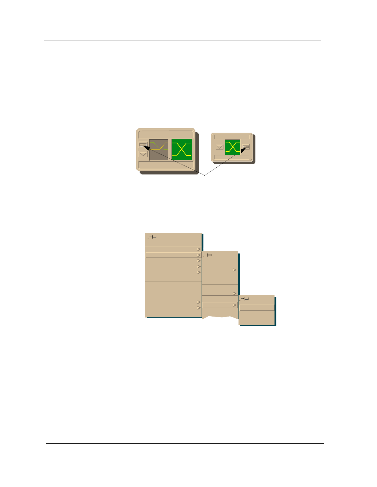
The following diag ram illu str ate s ho w to acc es s the Gigaswitch’s Logical
Device view and F igur e 2-1 shows the module’s Logical De vic e view. The
Logical Device v iew p rovide s ac cess to d etaile d info rmati on abou t the
Gigaswitch module. Figure 2-2 displays the Gigaswitch Logic al Mod ule and
the menu selections available by double-clicking the left mouse button on each
zone of the module.
9031754 E5
2-1
Logical Device View
Access in g th e Logical D e vi ce View
Acces si ng the Lo gical Devi ce V ie w
The Logical Device view is accessed using one of the following methods:
• Double-click on t h e D evice view button of the Gigaswit c h device icon. T his
will open the Device view that was opened last (i.e. L ogica l, P hys ical , or
Interface).
Device View Button
• Highlight the DEC Gigaswitch device icon and select Device -> Logical
from the Icon Subviews menu.
Go Back
Go Up
Icon Subviews
View Path
New View
Bookmarks
View History
Curre nt View Info...
Notes...
Jump by name...
Zoom
Map Hierarchy
Close
Navigate
Alarms
Performance
Notes...
Utilities
Zoom
Device
DevTop
Logical
Physical
Interface
Device View DEC GigaSwitch
2-2 Management Module Guide

Logical Device View
Accessing the Logical Device View
Figure 2-1. DEC Gigaswitc h Logical Device View
Primary Landscape 0x00400000 - VNM Host -GigaSwitch of type DECGigaSwitch
*File View Help?
Model N ame
Contac t
Descriptio n
Locati on
1
Net Addr
Prime-App
23456789
FGL2
FGL2 CLOCK SCP
9
Run
Run
13
Spanning
Spanning
Run
Run
14
10
Spanning
Spanning
Run
13
Spanning
Run
14
Spanning
Sys U p Time
Manufa ct ure r
Device T ype
Seri a l Nu mb er
10 1 1 12 13 14
9031754 E5 Device View
2-3

Logical Device View
Access in g th e Logical D e vi ce View
Figure 2-2. DEC Gigaswitch Logical Device View - Label and Double-Click Zones
Module Number/
Module Notes view
FGL2
13
Spanning
14
Spanning
Table 2-1. Module Menu Selections
6
Run
Run
Port Status/
Port Config uraton view
Port Number/
Port Notes vie w
Port Applicatio n/
STP Tab l e vi ew
Menu Select io n Description
Module Notes Opens the Module Notes view, allowing you to
write, save, and email notes about the highlighted
module.
Module Port Table Opens the Module Port T able view, which displays
the module’s numbe r, its ports, the MIB II Index
and Bridge Ports.
Module Configuration Opens the Board Table view, allow ing you to
change the DEC Gigaswitch’s status. NotPr es e nt ,
PowerDown, PowerUp, PowerDownT he Up ,
Fault, RevMismatch, and SelfTestInProgress
are the status choices. For more information, refer
to Chapter 3, Configuration Views.
Device View DEC GigaSwitch
2-4 Management Module Guide

Table 2-2 list the icon subviews available from a highlight ed po rt in the
Logical Device view.
Table 2-2. Port Icon Subviews
Menu Select io n Description
Port Notes Opens the Port Notes view, allowing you to write,
Port Configuration Opens the FDDI MAC Table v i ew, providing FDDI
Spanning T ree Opens the STP Table v iew, allowing you to Enable
Interface Device View
Interface Device View
save and email notes about the highlighted port.
configuratio n information for the highlighted port.
For more information about the FDDI MAC Table
view and other configur ation views, refer to
Chapter 3, Configuration Views.
or Disable Spanning Tree capability for the
highlighted port.
This section descr ibe s the m o dule info rmat io n available from the Interfac e
Device view, which displays a Device Icon Pan el, an Inter f ace Op tions Panel,
and a Logical Interface icon. Access the Interface Device view by se lecti ng
Device from the Icon Subviews Menu or double-click the Device view button.
Access the Interface Device View using one of the following methods:
• Double-click on the Devic e view button of the Gig aSwitch dev ice ic on. This
will open the Device view that was opened last (i.e. Chas sis, Ph ysical or
Interface).
Device View Button
9031754 E5 Device View
2-5

Interface Device View
• Highlight the GigaSwitch device icon and select Devic e -> Inter f ace
from the Icon Subviews menu.
Go Back
Go Up
Icon Subviews
View Path
New View
Bookmarks
View History
Current View Info...
Notes...
Jump by name...
Zoom
Map Hierarchy
Close
Navigate
Alarms
Performance
Notes...
Utilities
Zoom
Device
DevTop
Chassisl
Physical
Interface
The Interface Device View includes three panels as well as the Device View
Banner sh ow n in F igure 2-3.
Device View DEC GigaSwitch
2-6 Management Module Guide

Interface Device View
Figure 2-3. Interface Device V iew
GigaSwitch of type DECGigaSwitch of Landscape VNMHost:Primary
*File View Help?
Model Name
Contac t
Descriptio n
Locati on
7
FDDI
8:0:2B:B3:1D:24
0
8
FDDI
8:0:2B:B3:1D:23
0
13
FDDI
8:0:2B:B3:1D:34
ON
ON
ON
Net Addr
Prime-App
Find
Interface Description
Phy Addr
Sys Up Time
Manufacturer
Device T ype
Serial Number
Networ k Infor mati on
Address
0
ON
14
FDDI
8:0:2B:B3:1D:33
0
9031754 E5 Device View
2-7

Interface Device View
Device Icon Pane l
Device Icon Panel
The Device Icon Panel displays the GigaSwitch Location view Icon.
Interface Options Panel
The Interface Option Panel area of the Device view allows you to modify the
presentation of the Logical Interface Icon. It provides the fields described
below as well as access to the Ga ug e Con trol P ane l view.
Filter
The Filter area of the Interface Options Panel is only implemented if the
SPECTRUM Routing Services Management Module is loaded.
Network Information
The Network Information area of the Interfac e Opti on s Panel allows you to
determine the interface information displayed in the Network Information
Label zone of that interface’s Logical Interface Icon. Possible selections are
ADDRESS, NAME, or MASK.
Interfac e Desc ri ption
Selecting an Interface Icon displays the type of interface in the Interface
Description area of the Interface Options Panel.
Device View DEC GigaSwitch
2-8 Management Module Guide

Logical Interface Icon
The logical interfac e icon dis plays information abou t each o f the int erfaces on
the line cards installe d in the Gig aSwitch
Interface Device View
Logical Interface Icon
Close
Navigate
Alarms
Performance
Notes...
Utilitie s
DevTop
Detail
IF Status
IF Configuration
IF Address Translation Table
Network Information Panel
Thresholds
Model Informati on
a) DevTop view/Port Number Label
b) Interface Status view/Interface Status Label
c) Interface Configuration view/Interface Label
d) Interface Address Tranlation Table/Physical Address Label
e) Network Information Panel/Network Information Label
f) CSI Interface Performance view/Logical Gauge
(a)
1
(b)
ON
ISO880 25
0:0:B8:6 8:9 9:30
132.177.24.118
0
(c)
(d)
(e)
(f)
Device Topology View/ I nterface Number Lab e l
This label displays the nu m be r of this inte r face . Dou ble -clic k ing on this labe l
allows you to access the DECGigaSwitch Device Topology (DevTop) view.
Interface Status View/Interf ace Status Label
The Interface Status Label display s a text label and an app ropri ate
background color to represen t the curr en t statu s of the interface. T a ble 2-3
shows the pos sible inte r face statuses and the ir re spe c tive co lo rs.
9031754 E5 Device View
2-9

Interface Device View
Logical Interface Icon
Table 2-3. Interface Status Label Definitions
Operational
Status
ON ON ON Green
OFF OFF OFF Blue
OFF ON OFF Ye llow
TESTING TESTING TEST Red
Administrative
Status
Text Display Color
The interface status label provides access to the status view specific to the
port. Double-clicking on this label opens the Interface Status view. This view
allows you to set the admin istr a tiv e sta tus to ON or OF F.
Interface Configuration View/Port Type Label
The Port Type Label displays the type of DE C GigaSwitch interfac e. Pos sible
interface type s ar e sho wn in Table 2-4.
Double-clickin g on the inte r face typ e label di splays the Interface
Configuration view. This view allows you to set the Administrative Status of
the highlighted interface to On, Off, o r Testing.
The Interface Configurat i on vie w also displa y s the inter f ace’s Operation
Status, Physic al A dd ress, Bandwidth, Pac k et Size, Que ue Length, Las t
Change information as read-only values .
T ab l e 2-4. Inte rf ace Types fo r the DEC GigaSwitc h
Interface Type Description
other None of t h e fo l lowin g
regular1822 Regular 1822
hdh1822 HDLC Distant Host protocol
ddn-X25 Defense Data Network X.25
rfc877-x25 RFC877 X.25
ethernet-csmacd Ethernet CSMA/CD
iso88023-csmacd ISO CSMA/CD
iso88024-tokenRing ISO token bus
iso88025-tokenRing ISO token ring
iso88026-man ISO man
Device View DEC GigaSwitch
2-10 Management Module Guide

Interface Device View
Logical Interface Icon
Table 2-4. Interface Types for the DECGigaSwitch (Continued)
starLan StarLAN IEEE 802.3
proteon-10Mbit ProNET 10 Mbps
proteon-80Mbit ProNET 80 Mbps
HyChan Hyperchannel
fddi Fibe r D i str i b uted Data Inter face
lapb X.25 Line Access Proced ure, Balanced
sdlc IBM Synchronous Data Link Control protocol
ds1 T1 link (USA and Japan)
CEPT T1 link (Europe)
basicISDN Basi c Integrated Services Digital Network
primaryISDN Proprietary Integrated Servic es Digital Network
propPointToPointSerial Proprietary Point to Point Serial
ppp Point to Point protocol
softwareLoopback Software Loop back
eon/CLNPoverIP Connectionless Network Protocol over IP
ethernet-3Mbit Ethernet 3 Mbps
nsip/XNSoverIP Xerox Network Service Protocol over IP
slip Generic Serial Line IP
ultra ULTRA Technologies
sip Switched Multimegabit Data Service
frame-relay T1 Frame relay
Interface Address Translation Table/MAC A ddress Label
The MAC Address Label displays the physical address of each of the
interfaces for the line card s insta lle d in the DEC GigaSwitch. Double -clic k ing
on this label accesses the Interface Address Tranlation Table.
The Interface Translation Table displays the Interface Index number, the
Physical Address, and the Network Address for each int erface.
9031754 E5 Device View
2-11

Interface Device View
Logical Interface Icon
Network Information Panel/Network Information Label
The Network Informati on Labe l displ a ys the name, addres s , or s ubn et mask
of this interface, according to selections made in the Interface Options Panel,
(see Inter f a c e Options Pa nel on page 2-8) .
Double-clic kin g on this label displays th e Ne twor k Inf ormation Panel,
displaying the name, address, and subnet mask of this interface.
Interface Performance View/Logical Gauge Label
Double-clickin g on this label of the Interface Ico n allows you to access the
Performance View for the interface. You can also access this view by
highlighting the GigaSwitch icon an d selecting Performance from the Icon
Subviews menu. This area is also a Logical Gauge, which is described later in
this chapter. The Performance view summarizes network traffic flow in
packets for this interface, providing th e fo llowing informatio n:
Multi-Attribute Line Graph
The Multi-Attribute Line Graph provides a general indication of network
activity. The attributes are pre-selected and use colors to represent different
statistics. For mo re inf orm ation on the Mul ti-A ttr ibut e L ine Graph, refer to
SPECTRUM Views. Table 2-5 lists the color and statist ical de f init ion s for
each attribute.
Table 2-5. Color and Statistical Definitions for each Attribute
Statistic Color Description
%
Transmitted
% Discarded Orange The percentag e of the total number of pack ets
% Error Red The percentage of the total number of packets
% Host
Bound
In Packet
Rate
Out Packet
Rate
Total Packet
Rate
White The percentage of the total number of packets
that have been transmitted, device-wide, during
uptime.
that have been discarded, device-wide, during
uptime.
that have contained errors, device-wide, during
uptime.
Yellow The perc entage of the total number of packets
that have been delivered to the local host from
the port during uptime .
Light Blue The total number of packet s th at have been
received, device-wide, dur ing uptime.
Turquoise The total number of packet s that have been
transmitted, device-wide, during uptime.
Royal Blue The total number of pack ets that have been
transmitted and received , device- w ide, during
uptime.
Device View DEC GigaSwitch
2-12 Management Module Guide

Interface Device View
Logical Interface Icon
T abl e 2-5. Color and Statistical Definitions for each Attribute (Continued)
Stat is tic Color De s cript ion
In Load Green T he amount of bandwidth us ed pe r packets
received d u ring the port’s uptime.
Out Load Mustard Green The amount of bandwidth used per packets
transmitted during the port’s uptime.
Total Load Light Green The amount of bandwidth used per pac kets
receive d and trans m i tt e d du r in g th e port’s
uptime.
Multi-Attribute Line Graph Buttons
Buttons allow you to modify the s tatistic al presentati on of the Multi -Attribute
Line Graph. The following buttons are provided:
Lin/Log
This button toggles between a linear or logarithmic scale presentation of the
graph.
Scroll to Date-Time
This button allows you to set the vi ew ing area of the gr aph to begin at a
specified date and time. When pressed, this button also displays two other
choices.
Choosing Change Time Scale allows you to set the time scale for the graph
within the range of 1 to 100 hours.
Choosing Data Logging allows you to store the polle d d ata in th e database.
Transmit
Pressing this button brings up a m ulti-attribute line gr aph that only displays
information ab o ut packet s sent throu gh the interface.
Receive
Pressing this button brings up a m ulti-attribute line gr aph that only displays
information about packets received through the interface.
Detail
Pressing this button brings up the I nte r face Detail view for the highl igh te d
interface. This view displays information about the Packet, Error, and Discard
rates in three color-coded pie graphs.
Config
9031754 E5 Device View
2-13

Interface Device View
Pressing this button brings up the I nte r face Co nfiguration view.
(See Interface Configuration View/Port Type Label on page 2-10.)
Alarms
Pressing this button brings up the A lar m M ang er, listing the alarms, if any,
for the interfaces.
Events
Pressing this button brings up the E ve n t Log f or the Gig aSwitch model.
Threshold
Pressing th is button brings up the I nte r face Th re shold view, allowing you to
set the Load, Packet Rat e, Err o r Rate , and %Discarded thresh ol ds for th e
interface.
Gauge Control Panel
The Gauge Control Panel allows you to change the type of statistical
information presented in the Logical Gauge area of the Logical Interface Icon.
To access the Gauge Co ntrol Panel, either dou ble - click on th e Int erf ace
Options Pane l or single-click on the pane l to high light it and then selec t
Gauge Control Panel from the Icon Subviews menu.
Selected Attribute
This area of the Gauge Control Panel allows you to select the statistical
attribute displ ayed on the Logi cal Interface Icon’s Gauge. The label changes
color to reflect the attribute selected. Table 2-6 and Table 2-7 provide a list of
the attribute s and thei r corresponding colors.
Gauge Mode
This area of the Gauge Control Panel allows you to select the mode presented
by the Logical Gaug e . Possible se lections are Totals, Rates, or Pe rcen tage s .
The Percentages selection represents the percentage of the interface
compared to the rest o f the inte rfac es. Table 2-6 shows the display ed
attributes and their color defin itio ns if the Totals mode is selected. Table 2-7
shows the displayed attributes and their color definitions if the Rates mode is
selected.
Device View DEC GigaSwitch
2-14 Management Module Guide

T ab le 2-6 . G au ge Totals Mode Attribute an d Color Def in itions
Selected Attribute Color
Errors Orange
In Packets Lt. Blue
Out Packets Lt. Blue
In Octets Green
Out Octets Green
Discards Tan
Forwarded Lt. Purple
Host Bound Yellow
Transmitted White
Filtered Gr ay
Interface Device View
Gaug e C on t ro l Panel
Table 2-7. GaugeRates Mode Attribute and Color Definitions
Selected Attribute Color
Load Green
Load In Green
Load Out Green
Packet Rate Lt. Blue
In Packet Rate Lt. Blue
Out Packet Rate Lt. Blue
% Discard Tan
% Filtered Gray
% Forwarded Lt. Violet
% Host Bound Yellow
% Error Orange
% Transmitted White
Gauge Type
This option allows you to select either a numeric or linear representation of
the Logical G aug e.
9031754 E5 Device View
2-15

Interface Device View
Gauge Control Panel Buttons
Several buttons allow you to control the way the Gauge Control Panel
selections affec t the lo gic al inte r fa ce ico n. The Ga ug e con trol p ane l p rovides
the following butto n s:
Apply
Apply the cu rr en t sele ctions to the Logic al Gauge. The settin gs c a nn ot be
saved.
Keep Settings
Save the curre nt gau ge settings while runnin g Sp e ctr oGR A P H .
Reset
Reset back to the last Keep Settings selections.
Close
Close the Gauge Control Panel.
Default
Reset back to the defaul t attribute of Load.
Device View DEC GigaSwitch
2-16 Management Module Guide

Physical Device View
The Physical Device view provides a graphical representation of the DEC
GigaSwitch and provides access to the Notes, Port Table, and Configuration
views for each of the mod ules installed in the DEC Gig aSwitch.
Accessing the Physical Device View
The Physical De vic e view is acc e sse d usin g on e of the foll ow ing methods:
• Double-click on the Devi ce V iew button of the Gi gaswitc h device icon. Th is
will open the Device view that was opened last (i.e. L ogica l or Physic al).
Physical Device View
Device View Button
• Highlight the Gigaswitch device icon and select Devic e - > P hy sical from
the Icon Subviews menu.
Go Back
Go Up
Icon Subviews
View Path
New View
Bookmarks
View History
Curre nt View Info...
Notes...
Jump by name...
Zoom
Map Hierarchy
Close
Navigate
Alarms
Performance
Notes...
Utilities
Zoom
Device
DevTop
Logical
Physical
Interface
9031754 E5 Device View
2-17

Physical Device View
Accessing the Physical Device View
Figure2-4. DEC GigaSwitch Physical Device View
Primary Landscape 0x00400000 - VNM Host -GigaSwitch of type DECGigaSwitch
*File View Help?
Model Name
Contact
Description
Locati on
Net Addr
Prime-App
line c ard
1
2
A/S
1
B
line card
1
2
A/S
1
Sys Up Time
Manufacturer
Device Type
Serial Number
line card
1
2
A/S
1
B
B
clock card scp card
A/S
2
B
A/S
2
B
A/S
2
B
Device View DEC GigaSwitch
2-18 Management Module Guide

Physical Device View
Accessing the Physical Device View
Table 2-8 des cr ibe s the icon subviews accessible form the DEC Gig aSwitch’s
Physical Device View.
T ab l e 2-8. DEC GigaSw i tc h l Physical De v ice View- Modu le Icon Subviews
Menu Select io n Description
Module Notes Opens the Module Notes View, allowing you to
write, save, and email notes about the highlighted
module.
Module Port Table Opens the Module Port Table V iew, which displays
the module’s numbe r, its ports, the MIB II Index
and Bridge Ports.
Module Configuration Opens the Board Table view, allow ing you to
change the DEC Gigaswitch’s status. NotPr es e nt ,
PowerDown, PowerUp, PowerDownT he Up ,
Fault, RevMismatch, and SelfTestInProgress
are the status choices. For more information, refer
to Chapter 3, Configuration Views.
9031754 E5 Device View
2-19

Physical Device View
Accessing the Physical Device View
Device View DEC GigaSwitch
2-20 Management Module Guide

Configuration V iews
What Is in This Chapter
This chapter describes the configuration views available for the DEC
GigaSwitch module. These views allow you to access and change the
configuration settings for the DE C G igaS witch module, its Ri ng In and Ri n g
Out Ports, and its station ports. The DEC GigaSwitch module supports the
following the configuration views.
•Device
•Interface
•Module
•Port
Chapter 3
DEC GigaSwitch Device Configuration View
The Device Configuration View includes a device banner and the GigaSwitch’s
model name, contact status, and the nu m be r of interfaces attached to th e
module. The Device Vi ew also provides access to the Interface Configu rat i on
Table and the Interface Address Translation Table for the DEC
GigaSwitch.You can access the De vice Configur ation View throug h the Icon
Subviews Menu, or the icon double-click zones.
9031754 E5
3-1

Access in g th e D e vi ce Config u ra t i o n View
Accessing the D e vice Conf igu ration View
You can access the D evice C o nfiguration View throug h the I con Subviews
Menu, or the icon dou ble -clic k zones.
Model Name
Model Type
Double-click Configuration Label
• Highlight the DECGigaSwitch device icon and select Configuration from
the Icon Subviews menu.
Go Back
Go Up
Icon Subviews
View Path
New View
Bookmarks
View History
Current View Info...
Notes...
Jump by name...
Zoom
Map Hierarchy
Device
DevTop
Application
Acknowledge
Flash Green Ena bled
Configuration
Model Inf orm ation
Primary Application
The Device Configuration View provides the following information:
Inter face Ad dress Translation Table
The Interface Address Translation Table lists the number, physical address,
and network addr ess f or each in te rfac e installe d in th e GigaSwitch. Double-
Configuration V iews DEC GigaSwitch
3-2 Management Module Guide

clicking on one of the entries in the Interface Address T ranslati on Tabl e access
the Address T ranslation T able Infor mation View. This view allows you to enter
information about a new interface to be included in the Interface Address
Translation Table or to edit the information for an exis ting entry.
Interface Configurati on Table
The Interface Configuration Table displays information regarding the
interfaces attached to the GigaSwitch. The table headings and their
descriptions are Index, Descrip tion, Type, Bandwidth, Physic a l Address and
Operation Status. Doubl e-cli cking on one of the entries in the Interface
Configura tion Table accesses th e Int er face C o nfiguration View, which allows
you to change th e Adm inistrative Stat us fo r the inte r f ace to On, Of f , o r
Testing.The Interface Configuration view also includ es a Device Bann e r for
the GigaSwitch and the Op e rati on Statu s, Last Change, Physical Addre ss ,
Bandwidth, Packet Size and Queue Length for the selected interface.
Module Configuration View
Interface Configuration Table
Module Configuration View
Access the Module Co nf ig uration View by doing the followi ng:
1. Access the DEC Gig aSwitch Logical Devi ce View via the Icon Subviews
menu.
2. Highlight the approp ri at e module.
3. Select Module Configuration for the Icon Subviews menu, wh ich will
call the Board Ta b l e View.
Board Table View
The Board Tab l e View allows you to change the status for the highlig hted
modul e . Possi bl e configuration choi ce s are NotPresent, PowerDown,
PowerUp, PowerDownThenUp, Fault, RevMismatch, and
SelfTestInProgress. The Board Table View also displays the Index number,
Type, Hardware Rev, and Firmware Rev of the highlighted module.
9031754 E5 Configuration V iews
3-3

Port Configuration View
Port Configuration View
Access the Port C o nfigu ration View by following the ste ps be lo w:
1. Access the DEC Gig aSwitch Logical Devi ce View via the Icon Subviews
menu.
2. Highlight the approp ri at e port .
3. Select Port Configuration for the Icon Subviews menu.
FDDI MAC Table View
To change the Purger Enabl e sett i ng , do the following:
1. Click the Purge r Enable button so tha t it dis pla ys th e de sir ed setting;
either True or False.
2. Choose Save All Changes from the File menu and close out of the view.
To change the Restricted Token Timeout setting, do the following:
1. Enter the desire d set ting in the Restricted Token Timeout text box. The
default is 12500000.
2. Choose Save All Changes from the File menu and close out of the view.
The FDDI MAC Table View also displays read-only in form ation about the
highlighted port’s FDDI configuration information.
Configuration V iews DEC GigaSwitch
3-4 Management Module Guide

Chapter 4
Event and Alarm Messages
What Is in This Chapter
This chapter desc ribes th e ty p es of even ts an d ala rms ge n erate d by the DE C
GigaSwitch. Additionally , this appendix notes if an event is also mapped to an
identical alarm message, and provides any probable cause messages
corresponding to these alar ms.
DEC GigaSwitch Even ts a nd A larms
SPECTRUM supports the following events for the DEC GigaSwitch. Table 4-1
lists the generic eve nts an d alarms fo r DEC Gig aSwitch devices.
Table 4-1. DEC GigaSwitch Events and Alarms
Event Message Probable Cause Me ssage
Event00010306
{d "%w- %d %m-, %Y - %T"} - A(n) {t}
device, na me d {m } , h as be en col d
started . (event [{e}])
Event00010307
{d "%w- %d %m-, %Y - %T"} A(n) {t}
device, nam e d {m} has been w arm
started . (event [{e}])
No Probable Cause me ss ag e.
No Probable Cause me ss ag e.
9031754 E5
4-1

DEC GigaSwitch Events and Alarms
Table 4-1. DEC GigaSwitch Events and Alarms (Continued)
Event Message Probable Cause Me ssage
Event00010308
{d "%w- %d %m-, %Y - %T"} A(n) {t}
device, na me d {m } , h as det e ct e d a
communication Link Down. (event
[{e}])
Event00010309
{d "%w- %d %m-, %Y - %T"} A(n) {t}
device, na me d {m } , h as det e ct e d a
communication Link Up. (e vent [{ e}])
Event0001030a
{d "%w- %d %m-, %Y - %T"} A(n) {t}
device, na me d {m } , h as det e ct e d an
Authentication Failure. (event [{e}])
Event0001030b
{d "%w- %d %m-, %Y - %T"} A(n) {t}
device, na me d {m } , h as det e ct e d an
EGP Neighbor Loss. EGP Neighbor
IP address is {O 1}. (event [{e}])
Prob00010308
Communication link is down.
No Probable Cause me ss ag e.
Prob0001030a
Authorizatio n fail ure. Other user is tryi ng
to connect to device with an invalid
community string.
Prob0001030b
Lost contact with EGP neighbor.
Event01540003
{d "%w- %d %m-, %Y - %T"} - Board {I
1} repo rts a f ail ure on dev ice {m} ({t} ).
(even t [{ e}])
Prob01540003
The GigaSwitch re cognizes a failure i n one
of the communications slot represented in
the agent’s configuration.
Event and Alarm Messages DEC GigaSwitch
4-2 Management Module Guide

Chapter 5
DEC-Specific Applications
What Is in This Chapter
This chapter desc ribes th e Dec E lan A pp an d the DecGig aA p p accessible
through the GigaSwitch’s Application s View.
DecGigaApp
The DecGigaApp allows the user to perform basic co nfig ur a tion processes for
the GigaSwitch , to acces s bridg e in form atio n for th e switch , to conf ig ur e
filters, and to upgrade the firmware for specific cards. Figure 5-1 illustrates
the Icon Subviews menu for the DecGigaApp.
9031754 E5
5-1

DecGigaApp
Configuration
Figure 5-1. The DecGigaApp Icon Subviews menu
Navigate
U
tilities
Notes...
Zoom
E
vents
A
larms
Configuration
GigaSwitch ARP
GigaSwitch Bridge Statistics
GigaSwitch Cut Through Mapping
GigaSwitch Filters
GigaSwitch M Ports
GigaSwitch STP
Upgrade
Attribute Walk
Model Information
These icon subviews allow the user to perform configuration tasks for the
GigaSwitch or to view st atistics relating to the Gig aSwitch’s performance .
Configuration
The DecGigaApp C onfiguration View allows the user to specif y th e follo win g
settings for the DE C GigaSwitch:
Primary Application
Dictates what application will be analyzed in the GigaSwitch’s Performance
View. The user can choose from a list of SPECTRUM and GigaSwitch
applications.
Memory
The user can specify Rewrite, Rewriting, or Other for the Memory setting.
Fan Speed
The user can select either Maximum or Normal for the GigaSwitch’s fan
speed.
SNMP Dupli ca te Di sc ard Interv al
The user can specify the interval (measured in 1/100 sec) at which a duplicate
packet is discarded. The default setting is 50.
DEC-Specific Applications DEC GigaSwitch
5-2 Management Module Guide

DecGigaApp
GigaSwitch ARP
In addition to these co n fig ur atio n sett ing s, th ree butto n s pro vid e acc es s to
tables detailing information on the boar ds withi n the Gig aSwitch, the
hardware and firmware specifications f or the GigaSwitch, and th e
information o n the GigaSwitch’s power supp ly.
Boards
This table provides info rmation on individual boa rds in th e Gi gaSwitch.
Information is ca tegoriz e d b y I nd ex, Type, Stat us, Hardw are Revi sion, and
Firmware Revisio n. Double-clickin g on an e ntr y will access the Boar d Table
View. The Board Table View allows the user to choose the status of a
particular board. The following cho ices ar e available : NotP r esent,
PowerDow n, Po werUp, PowerD ownThen Up, Fau lt, RevMismatch , and
SelfTestInProgress.
PSC Cont roller
This table allows the user to choose to Heed or Ignore the temperature
warning, should the GigaSwitch overheat as well as detailing information on
the Gig aS witch ha rd ware and f irm ware.
Power Supply
This table shows the Status, Input Source, and Output information for the left
and right powe r supply sour ce s.
GigaSwitch ARP
ARP Agent
The user can specify whether the ARP Agent is on or off.
Timeout
The user can specify the timeout setting in seconds.
Period Between
The interval, measured in seconds, between the ARP Agent trying to resolve
an IP and MAC address.
Retries
The user can specify the number of times the ARP agent will try to reconcile
an IP and MAC address.
The GigaSwitch ARP table details the IF Index, Unicast Receive,
Broadcast Receive, Replies trns, Frames Flood, and Frames Discarded
information fo r the Gig aSwitch ARP.
9031754 E5 DEC-Specific Applications
5-3

DecGigaApp
GigaSwitch Bridge Statistics
GigaSwitch Br idge Statistics
The GigaSwitch Bridge Statistics icon subview menu accesses the
GigaS witch Flooding Table.
Unkno wn Unicast Rate
Maximum bytes-per-s ec ond ba ndwi dt h of packets multic ast be cause t he
destination addre ss was no t yet le arn e d by the the bridge .
Multicast Rate
The maximum bytes-per-second bandwidth of packets multicast because the
destination address is a multicast address.
The Flooding Table details the Quali fi er, Class, Bytes Sent, Packets Sent,
Geezers, Losers, and Hogs informat i on for each of the active cards on the
GigaSwitch.
GigaSwitch Cut Through Mapping
The GigaSwitch Cut Through Mapping table allows the user to enable or
disable the Inbound or Outbound Cut Through Mapping application for each
of the GigaSwitch Bridge Ports. The Cut Through Mapping feature allows
packets with kn o wn IP addr e sses to trav el through the GigaSw itc h with ou t
being temporarily stored within the GigaSwitch. Packets without known IP
addresses for their d estination are temporar ily d elaye d whi le the GigaSwitch
learns the IP address.
The default settin g for eac h of the Br id ge Por ts is E nabled for both the
Inbound and Outbound Cut Through Mapping applications.
Configuring Cut Through Mapping
1. Double-cli ck on the appropriate Bridge Port number to generate the Cut
Thro ugh Table View.
2. Click on the Inbou nd and Outbound butto ns so that they display the
appropriate settin gs, ei t her Enabled or Disabled.
3. Choose Save All Changes from the File menu.
4. Click on the Update button in the Cut Through Map p ing table to view
your changes.
DEC-Specific Applications DEC GigaSwitch
5-4 Management Module Guide

GigaSwitch Filters
The GigaSwitc h F ilters icon subview allows the user to config ur e Port
Matrices, Desti na tio n F ilters, SAP Filters, SNAP Filters, and Source
Filters. These port matrices and filters can be configured to restrict traffic
from certain ports to a portion of the network, to isolate a device while
troubleshooting or to improve performance between ports by establishing a
path for the packe ts tr ave lin g be twe en those ports.
Port M a trices
The Port Matrices Table allows the user to edit or add a matrix for a port.
Editi ng Existing Matrices
1. Double-click on the ma tr ix setting to be changed to display the Port
Matrix View.
2. Edit the Name, the Ma t ri x Value (for the bridge), t he Mat ri x Value (for
the front panel), and the Status settings so that they display the desired
values.
DecGigaApp
GigaSwitch Filters
3. Choose Save All Changes from the File menu to close out of the Port
Matrix View.
Adding a Matrix to the T able
1. Click the Add an E ntr y butt on to displa y the A dd a Por t Matrix View.
2. Enter the name of the m atr ix in the Name text box.
3. Fill in the value for the matr ix in th e Matrix text box.
4. Click the Status button so that it display s the ap prop ri ate value (either
Perman e nt or Invalid).
5. Choose Save All Changes from the File menu.
6. Click on the Add Entry butto n to save the matrix and place it in the table.
9031754 E5 DEC-Specific Applications
5-5

DecGigaApp
GigaSwitch Filters
Editing Destination Filters
The Destinatio n F ilter icon subview generates the GigaSwitch Port FilterDestination Address Table. The user has the option of editing the settings for
an existing filter or addin g a ne w filte r to the table.
1. Double-click on the setting you wish to change, displaying the Destination
Filter View.
2. Edit the settings yo u w ould like to chan ge.
3. Choose Save All Changes from the File menu and close out of the
Destination Filter View .
Adding Entries to the Destination Filters Table
1. Click the Add an Entr y butt on to displa y the Ad d a Desti nati on Filt er
View.
2. Enter the appropriate Name for the filter.
SAP Filters
3. In the Destination text box, enter the MAC addres s of the d evic e to be
filtered.
4. In the Matrix text box, enter the matrix value for the filter.
5. Choose the dispos i tion (Filter, Always Filter , or Forward) for the filter,
using the Disposition button. Click on the Status button so that it displays
the desired status (Other, Invalid, Permanent, Dele t e OnReset, or
DeleteOnTimeOut).
6. Choose Save All Changes from the File menu.
7. Click on the Add Entry button to save the matrix and p lace it in the
table.
The SAP Filter icon subview generates the GigaSwitch Port Filter-SAP Table.
The user has the option of editi ng the sett ings for an existi ng filter or adding a
new filter to the table.
DEC-Specific Applications DEC GigaSwitch
5-6 Management Module Guide

DecGigaApp
GigaSwitch Filters
Editing the Settin gs for a n Exi stin g Fi lter
1. Double-clic k on the se tting you wish to cha nge , whic h gene r a tes the SAP
Protocol Filter View.
2. Edit the settings yo u w ould like to chan ge.
3. Choose Save All Changes from the File menu and close out of the
Destination Filter View .
Adding an Entry to the SAP Filter View
1. Click the Add an Entry button to generate the Add an SAP Filter
View.
2. Enter the appropriate Name for the filter.
3. In the Protocol text box, enter the SAP protocol to be filtered.
4. In the Matrix text box , ente r th e matr ix value for the filter.
SNAP Filters
5. Choose the dispos i tion (Filter, Always Filter , or Forward) for the filter,
using the Disposition button in the view. Click on the Status button so
that it displays th e de sir ed sta tus ( Other, Invalid, Permanent).
6. Choose Save All Changes from the File menu.
7. Click on the Add Entry button to add the new filter to the table.
The SNAP Filter icon subview gene r ate s the GigaSwitch Port Filter-SN A P
Protocol Table. The user has the option of editing the settin g s for an existing
filter or adding a new filter to the table.
Editing an Existing SNAP Filter
1. Double-clic k on the se tting you wish to cha nge , disp layin g the S NA P
Filter View.
2. Edit the settings yo u w ould like to chan ge.
3. Choose Save All Change s from the File menu and close out of the SNAP
Filter View.
9031754 E5 DEC-Specific Applications
5-7

DecGigaApp
GigaSwitch Filters
Source Filters
Adding a SNAP Filter to the Table
1. Click the Add an Entr y butt on to displa y the Ad d an SNAP F ilter View.
2. Enter the appropriate Name for the filter.
3. In the Protocol text box, enter the SNAP protoco l to be filtered.
4. In the Matrix text box , ente r th e matr ix value for the filter.
5. Choose the dispos i tion (Filter, Always Filter, or Forward) for the filter,
using the Disposition button in the view. Click on the Status button so
that it displays th e de sir ed sta tus ( Other, Invalid, Permanent).
6. Choose Save All Changes from the File menu.
7. Click on the Add Entry button to add the new filter to the table.
The Source Filter ico n su bview ge n er ate s th e Gi gaSw itc h Por t Filt er-Sou rc e
Address Table. The user has the option of editing the settings for an exist i ng
filter or adding a new filter to the table.
Editing an Existing S ource Filter
1. Double-clic k on the se tting you wish to cha nge , disp layin g the So ur ce
Filter View.
2. Edit the settings yo u w ould like to chan ge.
3. Choose Save All Ch an ge s fr om t h e File menu and clos e out of the Sourc e
Filter View.
Adding a Source Filter to the Table
1. Click the Add an Entry button, displaying the Add a Source Filter View.
2. Enter the appropriate name for the filter.
3. In the Source text box, enter the MAC address of the source you would like
to filter.
4. In the Matrix text box , ente r th e matr ix value for the filter.
DEC-Specific Applications DEC GigaSwitch
5-8 Management Module Guide

5. Choose the dispos i tion (Filter, Always Filter , or Forward) for the filter,
using the Disposition button in the view. Click on the Status button so
that it displays th e de sir ed sta tus ( Other, Invalid, Permanent,
DeleteOnRese t, or DeleteOnTimeOut).
6. Choose Save All Changes from the File menu.
7. Click on the Add Entry button to add the new filter to the table.
GigaSwitch M Ports
The GigaSwitch M P orts ic on subv ie w gene r ate s the Giga S wit ch M Port
Table.
Enabling or Disabling a Particula r M Port
1. Double-click on the Enable setting for the particular port to display the M
Port Table View.
DecGigaApp
GigaSwitch M Ports
2. Click on the Enable button so that it displays the desired setting (True or
False).
3. Choose Save All Changes from the File menu and close ou t of the M Port
Table View.
GigaSwitch STP
The GigaSwitc h ST P icon subview generate s th e GigaSwitch STP T able .
Enabling or Disabling the Spanning Tree Application for a Particular Port
1. Double-click on the Enable setting for the particular port to display the M
Port Table View.
2. Click on the Enable button so that it displays the desired setting (True or
False).
3. Choose Save All Changes from th e File menu and close out of t h e M Port
Table View.
9031754 E5 DEC-Specific Applications
5-9

DecGigaApp
Upgrade
Upgrade
The Upgrade icon subview allows the user to download new firmware for a
particular card in the Gig aSwitch.
Upgrading Card Firmware
1. Click on the Upgrade icon subview.
2. Enter the TFTP (T riv ial File Transf er Protocol ) Destina tion addre ss or the
MOP (Maintenance Operation Protocol) Destination address in the TFTP
Destination or MOP Destination text box.
3. In the Fil e Name text box , enter the filename of the firmware revision you
wish to download.
4. Click the Action butt on so that it d isplays either DoM OP or DTFTP.
5. Enter the card’s slot number in the Slot to Upgrade text box.
6. Click the Upgrade Action but to n so that it disp lay s DoUpgrade.
7. To cancel the fi le transfer, click t he Delete Transfer button and choos e the
appropriate option.
Model Information View
The model information icon subview provides the user with a list of
SPECTRUM’s settings for the GigaSwitch model. The Poll Interval used by
many of the SPECT R U M appl icat ion s must be set in the application’s Model
Information View.
Setting the Poll Interval
1. Click on Model Information in the icon subviews menu.
2. Enter the desired poll interval in the Poll Interval text box.
3. Click on the Polling Status button so that it displays True.
DEC-Specific Applications DEC GigaSwitch
5-10 Management Module Guide

DecElanApp
This application fo r the Gig aSwitch provides the use r with m o re stat istical
tables, the ability to add or remove trap receivers, and the ability to add either
Read-Only or Read-Write management st atio ns .
To access the DecElanApp, click on the Applications subview for the DEC
GigaSwitch icon. The Dec E lanApp allows the user access to the following
views:
Configuration
The DecElanApp Configuration View allows for the following settings to be
edited by the user:
Primary Application
The user may choose the applicat ion that they wish to be detailed in the
Performance View.
DecElanApp
Update Switch
The user may speci f y whet her t he s w itch should be updated or n ot b y c lic ki ng
on the Update Switch button so that it shows the des ire d setting (True or
False).
Port Traps
The user may enable or disable port traps by clicking on the Port Traps
button so that it show s the d esire d se ttin g (E nable or Disable).
Init Switch
The user may choose between Other, Reset or ResetWithDefaults for this
setting.
Gateway
The user may spec if y the gate way used for downloading firm ware.
FRU Configuration
This button accesse s th e FR U Conf igu rati on Table, which displays the Slot,
Description, Rev , and State of the port’s firmware.
Bridg e Da t aba s es
The Bridge Databases icon subview accesses the 2-Port Address Table and the
Multi-Port Address Table. These tables display the Address, Port Number,
and Status of 2-Port and Multi-Port devices. In addition, the Multi-Port
Address table displa ys the R ece iv e Po rt and A llo w to Go To information for
each port.
9031754 E5 DEC-Specific Applications
5-1 1

DecElanApp
Extended Bridge
Extended Bridge
The Extended Bridge icon subview accesses another menu of subviews related
to the bridging statistics of the GigaSwitch.
Figure 5-2. The Extended Bridge Submenu
Charac teristics
Disable Spanning Tree
Ethernet Interfaces
FDDI Interfaces
Filtering Switches
Interfaces
NTP
Rate-Limiting
Status
Counters
Spanning Tree
Spanning Tree Ports
Characteristics
The following Extended Bridge subviews allow the user to choose various
settings.
The Extended Brid ge C haracteristics subvi ew allo ws the user to specify the
following characteristics:
Port Test Pass Thresh
The threshold number of successful, consecutive self-tests before the
GigaSwitch is considered operational.
Port Test Interval(S ec)
Upon a line break, the Gig aSwitch will test the failed por t. The Por t Test
Interval is the amoun t of time in seco n d s betwe e n the te sts o f a particu lar
port.
Manual Filter
Click the Manual Filter button so that it displa ys th e desir ed m an ual f ilter
condition. (True or False)
DEC-Specific Applications DEC GigaSwitch
5-12 Management Module Guide

Fragmentation
Click the Fragmentation button so that it displays the desired fragmentation
condition. (True or False)
Remove Mgmt Address
The user c a n choose betwee n Other and True. The initial setting is Other, but
selecting True will remove the management address.
Remove Mg mt Pr o toc o l
The user c a n choose betwee n Other and True. The initial setting is Other, but
selecting True will remove the management protocol.
Disable Spanning Tree
To enable or disable the Spanning Tree function for an individual port:
1. Double-click on the port’s number or status entry.
2. Click on the Status button so that it disp lay s the des ired statu s.
(Enable d or Disabled)
DecElanApp
Extended Bridge
NTP
Rate-Limiting
3. Choose Save All Changes from the File menu and close out of the view.
The Non-Translated Protocol Table al lows the user to sp eci fy the IPX(Raw) To
Snap condition as True or False. If the IPX(Raw) To Snap feature is enabled,
IPX(Raw) packe ts wil l be con ve rted into SN AP pa ck ets.
The Rate-Limiting subview allows the user to enable or disable the
Rate-Limitin g feat ur e for a pa rticular port and to set the Max R ate- L imit
Frames Per Second.
9031754 E5 DEC-Specific Applications
5-13

DecElanApp
Extended Bridge
Spanning Tree
The Extended Bridge Spanning Tree view allows the user to specify the
following Spanning Tree settings:
Short Agi n g Time( Se c s)
Enter the desired time (in seconds) in the text box. The default is 30.
Bad Hello Limit
Enter the desire d lim it in the te xt box. Th e de fault is 15.
Bad Hello Reset Timer
The number of seconds before a Bad Hello reset.
No Frame Interval(Secs)
The length of time (in seconds) of inactivity before the GigaSwitch initiates a
self test.
LB100 Poll Time(Secs)
The length of time (in seconds) between the polling of the LAN bridge.
LB100 Response Timeout(Secs)
The length of time (in seconds) the GigaSwitch waits for a response from the
LAN bridge.
Extended FDDI
Spanning Tree Mode
The user may specify the Spanning Tree Mode by clicking on the button so
that it displays Aut oS elec t existing or IEEE802 .
The Extended FDDI icon subview accesses the Full-Duplex Links Table, MAC
T ab l e, Port Table, and SMT T a bl e. The Full-Duplex Links Table and th e MAC
Table allow for user input.
Full-Duplex Links T able
To disable or enable the Duplex featu re:
1. Double-click on the de sired por t.
2. In the Full-Duplex Table View, click the Enable Duplex button so that it
displays True or False.
DEC-Specific Applications DEC GigaSwitch
5-14 Management Module Guide

MAC T a ble
To edit the Purger settings for a GigaSwit ch po rt:
1. Double-click on the de sired por t disp lay ed in th e MAC Table.
2. In the FDDI MAC Table View, cli ck on the Purger Enabl e button so that i t
displays either True or False.
3. In the Restricted Token Timeout text box, enter the desired value. The
default is 12500000.
4. In the Ring Latency text box enter the desired value (meas ur ed in
nanoseconds).
Protocol Databases
The Protocol Databases icon subview accesses the Ethernet Protocol, SAP
Protocol, and SNAP Protocol databases. These views allow the user to specify
whether the ports will forward or filter packets in each of these protocols.
DecElanApp
Protocol Database s
To change the 2-Port settin g for each of these protocol t ables:
1. Choose the desired database from the P rotocol Da tabase s icon subv iew.
2. Click on the 2-Port Setting button so that it displays either Forward or
Filter.
3. Choose Save All Changes from the File menu.
SNMP Authentication
The SNMP Authentication icon subview allows the user access to the SNMP
User Communities View and to the SNMP Trap User Table.
9031754 E5 DEC-Specific Applications
5-15

DecElanApp
SNMP Authenti cation
SNMP User Communities Table
The SNMP User Communities Table provides the ability to add Read-Only
managem e nt stations or mana ge m e nt stations with Re ad -Write permi ssio ns.
The SNMP User Communities View also allows the user to edit an existing
station’s mask and status.
To edit an existing station’s settings:
1. Double-clic k on one of its settings in the SNMP User Communities Table.
2. In the Read-Only Station or Read/Write Station view, make the
appropriate chan ges to the stati on ’s Mask and Status. The Status sett ing
may be Other or Invalid.
3. Choose Save All Changes from the File menu.
To add a new Read-Only or Read/Write station:
1. Click on the Add a Read -Only Ent ry or Add a Read/Write Entry
button.
2. In the Add a Station view, enter the station’s IP Address and its Mask.
3. Choose Save All Changes from the File menu.
4. Click the Add Entry button.
SNMP Trap User T able
The SNMP T rap User Tabl e provides for the est ablish ment of tra ps for device s
in a particular community. To edit an existin g tra p for a device:
1. Double-cli ck on one of th e device’s sett ings in t he SNMP T rap Us ers Table,
generating the Trap Station View.
2. Click on the Status button so that it displays the desired setting (Other or
Invalid).
3. Choose Save All Changes from the File menu.
To create a new trap:
1. Enter the communi ty strin g f or the device in the Trap Community text
box.
2. Enter the IP address for the device to be trapped in the IP Address text
box.
3. Choose Save All Changes from the File menu.
DEC-Specific Applications DEC GigaSwitch
5-16 Management Module Guide

Model Information View
The model information view prov id es the use r wi th a concise list of
SPECTRUM’s settings for the GigaSwitch model. The Poll Interval used by
many of the SPECT R U M appl icat ion s must be set in the application’s Model
Information View. To set the Poll Interval:
1. Click on Model Information in the icon subviews menu.
2. Enter the desired poll interval in the Poll Interval text box.
3. Click on the Polling Status button so that it displays True.
DecElanApp
Model Information View
9031754 E5 DEC-Specific Applications
5-17

DecElanApp
Model Information Vie w
DEC-Specific Applications DEC GigaSwitch
5-18 Management Module Guide

Index
Symbols
% Discarded 2-12
% Error 2-12
% Host Bound 2-12
% Transmitted 2-12
A
Accessing
Chassis Device View 2-2
Device Co nfiguration View 3-2
Physical Device View 2-17
Accessing Configuration View 3-2
Adding a Source Filter 5-8
ADDRESS 2-8
Admini strat ive Stat us 2-9
Applications 1-2
Apply Button 2-16
ARP Agent 5-3
Associations 1-1
ATM 1-1
B
Bandwidth 3-3
Board Table View 3-3
Boards 5-3
C
Characteristics 5-12
Chassis Device View 2-4
Close Bu t t on 2-16
Color and Statistical Definitions by
Application 2-12
Configurat ion Vi ews 3-1
Module 3-3
STHi Device 3-1
D
DEC GigaSwitch Manag ement Module 1-1
DecElanApp 5-11
Bridge Databases 5-11
Configuratio n 5-11
Extended Bridge 5-12
Extended FDDI 5-14
Model Information View 5-17
Protocol Databases 5-15
SNMP Authentication 5-15
DecGigaApp 5-1
Configuration 5-2
GigaSwitch ARP 5-3
GigaSwitch Bridge Statistics 5-4
GigaSwitch Cut Through Mapping 5-4
GigaSwitch Filters 5-5
GigaSwitch M Ports 5-9
Model Information View 5-10
Upgrade 5-10
DecGigaSwitch
GigaSwitch STP 5-9
DEC-Specific Ap p licat ions 5-1
Default
Button 2-16
Destination Filters 5-6
Device
Icon Panel 2-8
Device Congiguration View 3-1
Device Icon Panel 2-8
Device Topology View
Label 2-9
Device View 2-1
Chassis 2-1
Disable Spanning Tree 5-13
Discard 2-15
Discards 2-15
9031754 E5
1

E
Editing a SNAP Filte r 5-7
Editing a Source Filter 5-8
Error 2-15
Errors 2-14
ETWMIM
Models 1-2
Event and Alarm Messages 4-1
Event Messages 4-1
F
Fan Speed 5-2
FDDI MAC Table View 3-4
FGL-2 1-1
Fiber GIGAswitch/FDDI System Linecard 1-
1
Filtered 2-15
Find 2-8
Firmwa re R e visions 1-1
Forwarded 2-15
Fragmentation 5-12
FRU Configuration 5-11
Full-Duplex Li nk s Table 5-14
I
In
Load 2-12
Octets 2-14
Packet Rate 2-12, 2-15
Packets 2-14
Index 3-3
Init Switch 5-11
Interface
Description 2-8
Device View 2-4
Number Label 2-9
Options Pa ne l 2-8, 2-14
Performance View Label 2-12
Status
Label 2-9
Status Label 2-9
Interface Address Translation Table 3-2
Interface C onf iguration Table 3-3
Introduction 1-1
K
Keep Settings B utt o n 2-16
G
Gateway 5-11
Gauge
Control Panel 2-14
Buttons 2-16
Mode 2-14
Attribute Totals and Color
Definitions 2-14
Rate Attributes and Color
Definitions 2-15
Type 2-15
GigaSwitch ARP Table 5-3
GigaSwitch Flooding Table 5-4
Gray 2-15
Green 2-12, 2-14, 2-15
H
Host
Bound 2-15
L
Lin Button 2-13
Linear Scale 2-13
Load 2-15
In 2-15
Out 2-15
Log
Button 2-13
Logarithmic Scale 2-13
Logical
Gauge 2-14
Label 2-12
Interface Icon 2-8
Logical Devic e View 2-1
figure 2-3
menu selections 2-4
Module Menu Selections 2-4
Logical Interface Icon 2-9
Lt.
Blue 2-12, 2-14, 2-15
Green 2-12
Purple 2-15
Viol et 2-15
Index DEC GigaSwitch
2 Management Module Guide

M
M Por t s 5-9
MAC
Address
Label 2-11
MAC Table 5-15
Management
Information Base 1-1, 1-2
Manual Filter 5-12
MASK 2-8
Memory 5-2
MIB 1-1, 1-2
Module Configuration View 3-3
Module Menu Selections 2-4
Mult i-Att ribute Line Grap h 2-12
Buttons 2-13
Mustard Gr een 2-12
Physical Device View 2-17
Accessing 2-17
Icon Subviews 2-19
Poll Interval 5-10
Port
Type
Label 2-10
Port Co nfigu ration View 3-4
Port Matrices 5-5
Port Test Interval 5-12
Port Test Pass Thresh 5-12
Port Traps 5-11
Power Supply 5-3
Primary Application 5-2, 5-11
Probable Cause Messages 4-1
PSC Controller 5-3
R
N
NAME 2-8
Network
Information 2-8
Label 2-11
Panel 2-11
Notice i
NTP 5-13
O
OFF 2-9
ON 2-9
Operation Status 3-3
Operational Status 2-9
Orange 2-12, 2-14, 2-15
Out
Load 2-12
Octets 2-15
Packet Rate 2-12, 2-15
Packets 2-14
P
Packet
Rate 2-15
Percentages 2-14
Period Between 5-3
Physical A dd ress 3-3
Rate-Limiting 5-13
Rates 2-14
Red 2-12
Related Docum e nt atio n x iii
Related Reading xiii
Remove Mgmt Address 5-13
Remove Mgmt Protocol 5-13
Reset Button 2-16
Restricted Rights Notice ii
Retries 5-3
Ring Port C o nfiguration View 3-4
Royal Blue 2-12
S
SAP Filters 5-6
Scroll to Date-Time
Button 2-13, 2-14
Selected A t tribute 2-14
SNAP Filters 5-7
SNMP 1-1
SNMP Duplicate Discard Interval 5-2
SNMP Trap User Table 5-16
SNMP User Communities Table 5-16
Source Filters 5-8
Spanning Tree 5-14
Spanning Tree Application 5-9
SPECTRUM Administrator’s Reference xi
SPECTRUM Application View Reference
Guide 1-2
9031754 E5 Index
3

S (continued)
SPECTRUM Documentation xiii
SPECTRUM Operator’s Reference xi
STHi Device Co nfiguration View 3-1
Supported Cards 1-2
T
Tan 2-15
TEST 2-10
TESTING 2-10
Timeout 5-3
Total 2-14
Load 2-12
Packet Rate 2-12
Trademarks i
Transmitted 2-15
Turquoise 2-12
U
Update Switch 5-11
Upgrad ing F irm ware 5-10
V
Virus Disclaimer i
W
White 2-12, 2-15
Y
Yellow 2-12, 2-15
Index DEC GigaSwitch
4 Management Module Guide
 Loading...