

Cabletron Systems CyberSWITCH CSX400, CyberSWITCH CSX400-DC, CyberSWITCH CSX500, CyberSWITCH HSIM-W6, CyberSWITCH HSIM-W84 User Manual
Page 1

WAN Series
Local Management User’s Guide
for
Version 2.01.XX Firmware
(specified products only)
WAN Products affected by this manual:
CSX400 HSIM-W6
9032672-03
CSX400-DC HSIM-W84
CSX500
Page 2

Page 3

Only qualified personnel should perform installation procedures.
NOTICE
Cabletron Systems reserves the right to make changes in specifications and other information contained in this document without prior
notice. The reader should in all cases consult Cabletron Systems to determine whether any such changes have been made.
The hardware, firmware, or software described in this manual is subject to change without notice.
IN NO EVENT SHALL CABLETRON SYSTEMS BE LIABLE FOR ANY INCIDENTAL, INDIRECT, SPECIAL, OR
CONSEQUENTIAL DAMAGES WHATSOEVER (INCLUDING BUT NOT LIMITED TO LOST PROFITS) ARISING OUT OF OR
RELATED TO THIS MANUAL OR THE INFORMATION CONTAINED IN IT, EVEN IF CABLETRON SYSTEMS HAS BEEN
ADVISED OF, KNOWN, OR SHOULD HAVE KNOWN, THE POSSIBILITY OF SUCH DAMAGES.
1999 by Cabletron Systems, Inc., P.O. Box 5005, Rochester, NH 03866-5005
All Rights Reserved
Printed in the United States of America
Order Number: 9032672-03 April 1999
Cabletron Systems
All other product names mentioned in this manual may be trademarks or registered trademarks of their respective companies.
and
SPECTRUM
are registered trademarks, and
SmartSwitch
is a trademark of Cabletron Systems, Inc.
FCC NOTICE
This device complies with Part 15 of the FCC rules. Operation is subject to the following tw o conditions: (1) this device may not cause
harmful interference, and (2) this device must accept any interference received, including interference that may cause undesired
operation.
NOTE:
FCC rules. These limits are designed to provide reasonable protection against harmful interference when the equipment is operated in a
commercial environment. This equipment uses, generates, and can radiate radio frequency energy and if not installed in accordance
with the operator’s manual, may cause harmful interference to radio communications. Operation of this equipment in a residential area
is likely to cause interference in which case the user will be required to correct the interference at his own expense.
WARNING:
could void the user’s authority to operate the equipment.
This equipment has been tested and found to comply with the limits for a Class A digital device, pursuant to Part 15 of the
Changes or modifications made to this device which are not expressly approv ed by the party responsible for compliance
Local Management User’s Guide i
Page 4

Notice
INDUSTRY CANADA NOTICE
This digital apparatus does not exceed the Class A limits for radio noise emissions from digital apparatus set out in the Radio
Interference Regulations of the Canadian Department of Communications.
Le présent appareil numérique n’émet pas de bruits radioélectriques dépassant les limites applicables aux appareils numériques de la
class A prescrites dans le Règlement sur le brouillage radioélectrique édicté par le ministère des Communications du Canada.
NOTICE:
telecommunications network protective, operational and safety requirements as prescribed in the appropriate Terminal Equipment
Technical Requirements documents (s). The department does not guarantee the equipment will operate to the user’s satisfaction.
Before installing this equipment, users should ensure that it is permissible to be connected to the facilities of the local
telecommunications company . The equipment must also be installed using an acceptable method of connection. The customer should be
aware that compliance with the above conditions may not prevent degradation of service in some situations.
Repairs to certified equipment should be coordinated by a representative designated by the supplier. Any repairs or alterations made by
the user to this equipment, or equipment malfunctions, may give the telecommunications company cause to request the user to
disconnect the equipment.
Users should ensure for their own protection that the electrical ground connections of the power utility, telephone lines and internal
metallic water pipe system, if present, are connected together. This precaution may be particularly important in rural areas.
Users should not attempt to make such connections themselves, but should contact the appropriate electric inspection authority, or
electrician, as appropriate.
NOTICE:
terminals allowed to be connected to a telephone interface. The termination on an interface may consist of any combination of devices
subject only to the requirement that the sum of the ringer equivalence Numbers of all the devices does not exceed 5.
The Industry Canada label identifies certified equipment. This certification means that the equipment meets
Caution:
The Ringer Equivalence Number (REN) assigned to each terminal device provides an indication of the maximum number of
VCCI NOTICE
This is a Class A product based on the standard of the Voluntary Control Council for Interference by Information Technology
Equipment (VCCI). If this equipment is used in a domestic environment, radio disturbance may arise. When such trouble occurs, the
user may be required to take corrective actions.
ii Local Management User’s Guide
Page 5

Notice
CABLETRON SYSTEMS, INC.
PROGRAM LICENSE AGREEMENT
IMPORTANT: THIS LICENSE APPLIES FOR USE OF PRODUCT IN THE FOLLOWING GEOGRAPHICAL
REGIONS:
CANADA
MEXICO
CENTRAL AMERICA
SOUTH AMERICA
BEFORE OPENING OR UTILIZING THE ENCLOSED PRODUCT, CAREFULLY READ THIS LICENSE
AGREEMENT.
This document is an agreement (“Agreement”) between You, the end user, and Cabletron Systems, Inc. (“Cabletron”) that sets
forth your rights and obligations with respect to the Cabletron software program (“Program”) in the package. The Program may be
contained in firmware, chips or other media. UTILIZING THE ENCLOSED PRODUCT, YOU ARE AGREEING TO BECOME
BOUND BY THE TERMS OF THIS AGREEMENT, WHICH INCLUDES THE LICENSE AND THE LIMITATION OF
WARRANTY AND DISCLAIMER OF LIABILITY. IF YOU DO NOT AGREE TO THE TERMS OF THIS AGREEMENT, RETURN
THE UNOPENED PRODUCT TO CABLETRON OR YOUR DEALER, IF ANY, WITHIN TEN (10) DAYS FOLLOWING THE
DATE OF RECEIPT FOR A FULL REFUND.
IF YOU HAVE ANY QUESTIONS ABOUT THIS AGREEMENT, CONTACT CABLETRON SYSTEMS (603) 332-9400. Attn:
Legal Department.
1. LICENSE.
conditions of this License Agreement.
You may not copy, reproduce or transmit any part of the Program except as permitted by the Copyright Act of the United States or as
authorized in writing by Cabletron.
2. OTHER RESTRICTIONS.
3. APPLICABLE LAW.
courts of New Hampshire. You accept the personal jurisdiction and venue of the New Hampshire courts.
4. EXPORT REQUIREMENTS.
Government, including the U.S. Department of Commerce, which prohibit export or diversion of certain technical products to certain
countries, unless a license to export the product is obtained from the U.S. Government or an exception from obtaining such license may
be relied upon by the exporting party.
If the Program is exported from the United States pursuant to the License Exception CIV under the U.S. Export Administration
Regulations, You agree that You are a civil end user of the Program and agree that You will use the Program for civil end uses only and
not for military purposes.
If the Program is exported from the United States pursuant to the License Exception TSR under the U.S. Export Administration
Regulations, in addition to the restriction on transfer set forth in Sections 1 or 2 of this Agreement, You agree not to (i) reexport or
release the Program, the source code for the Program or technology to a national of a country in Country Groups D:1 or E:2 (Albania,
Armenia, Azerbaijan, Belarus, Bulgaria, Cambodia, Cuba, Estonia, Georgia, Iraq, Kazakhstan, Kyrgyzstan, Laos, Latvia, Libya,
Lithuania, Moldova, North Korea, the People’s Republic of China, Romania, Russia, Rwanda, Tajikistan, Turkmenistan, Ukraine,
Uzbekistan, Vietnam, or such other countries as may be designated by the United States Government), (ii) export to Country Groups
D:1 or E:2 (as defined herein) the direct product of the Program or the technology, if such foreign produced direct product is subject to
national security controls as identified on the U.S. Commerce Control List, or (iii) if the direct product of the technology is a complete
plant o r any major component of a plant, export to Country Groups D:1 or E:2 the direct product of the plant or a major component
thereof, if such foreign produced direct product is subject to national security controls as identified on the U.S. Commerce Control List
or is subject to State Department controls under the U.S. Munitions List.
You have the right to use only the one (1) copy of the Program provided in this package subject to the terms and
You may not reverse engineer, decompile, or disassemble the Program.
This License Agreement shall be interpreted and governed under the laws and in the state and federal
You understand that Cabletron and its Affiliates are subject to regulation by agencies of the U.S.
Local Management User’s Guide iii
Page 6

Notice
5. UNITED STATES GOVERNMENT RESTRICTED RIGHTS.
expense; (ii) contains “restricted computer software” submitted with restricted rights in accordance with section 52.227-19 (a) through
(d) of the Commercial Computer Software-Restricted Rights Clause and its successors, and (iii) in all respects is proprietary data
belonging to Cabletron and/or its suppliers. For Department of Defense units, the Product is considered commercial computer software
in accordance with DFARS section 227.7202-3 and its successors, and use, duplication, or disclosure by the Government is subject to
restrictions set forth herein.
6. EXCLUSION OF WARRANTY.
expressed or implied, concerning the Program (including its documentation and media).
CABLETRON DISCLAIMS ALL WARRANTIES, OTHER THAN THOSE SUPPLIED TO YOU BY CABLETRON IN
WRITING, EITHER EXPRESS OR IMPLIED, INCLUDING BUT NOT LIMITED TO IMPLIED WARRANTIES OF
MERCHANTABILITY AND FITNESS FOR A PARTICULAR PURPOSE, WITH RESPECT TO THE PROGRAM, THE
ACCOMPANYING WRITTEN MA TERIALS, AND ANY A CCOMPANYING HARDWARE.
7. NO LIABILITY FOR CONSEQUENTIAL DAMAGES.
LIABLE FOR ANY DAMAGES WHATSOEVER (INCLUDING, WITHOUT LIMITATION, DAMAGES FOR LOSS OF
BUSINESS, PROFITS, BUSINESS INTERRUPTION, LOSS OF BUSINESS INFORMATION, SPECIAL, INCIDENTAL,
CONSEQUENTIAL, OR RELIANCE DAMAGES, OR OTHER LOSS) ARISING OUT OF THE USE OR INABILITY TO USE THIS
CABLETRON PRODUCT, EVEN IF CABLETRON HAS BEEN ADVISED OF THE POSSIBILITY OF SUCH DAMAGES.
BECAUSE SOME STATES DO NOT ALLOW THE EXCLUSION OR LIMITATION OF LIABILITY FOR CONSEQUENTIAL OR
INCIDENTAL DAMAGES, OR IN THE DURATION OR LIMITATION OF IMPLIED WARRANTIES IN SOME INSTANCES,
THE ABOVE LIMITATION AND EXCLUSIONS MAY NOT APPLY TO YOU.
Except as may be specifically provided by Cabletron in writing, Cabletron makes no warranty,
The enclosed Product (i) was developed solely at private
IN NO EVENT SHALL CABLETRON OR ITS SUPPLIERS BE
CABLETRON SYSTEMS SALES AND SERVICE, INC.
PROGRAM LICENSE AGREEMENT
IMPORTANT: THIS LICENSE APPLIES FOR USE OF PRODUCT IN THE UNITED STATES OF AMERICA AND BY
UNITED STATES OF AMERICA GOVERNMENT END USERS.
BEFORE OPENING OR UTILIZING THE ENCLOSED PRODUCT, CAREFULLY READ THIS LICENSE
AGREEMENT.
This document is an agreement (“ Agreement”) between You, the end user, and Cabletron Systems Sales and Service, Inc. (“Cabletron”)
that sets forth your rights and obligations with respect to the Cabletron software program (“Program”) in the package. The Program
may be contained in firmware, chips or other media. UTILIZING THE ENCLOSED PRODUCT, YOU ARE AGREEING TO
BECOME BOUND BY THE TERMS OF THIS AGREEMENT, WHICH INCLUDES THE LICENSE AND THE LIMITATION OF
WARRANTY AND DISCLAIMER OF LIABILITY. IF YOU DO NOT AGREE TO THE TERMS OF THIS AGREEMENT, RETURN
THE UNOPENED PRODUCT TO CABLETRON OR YOUR DEALER, IF ANY, WITHIN TEN (10) DAYS FOLLOWING THE
DATE OF RECEIPT FOR A FULL REFUND.
IF YOU HAVE ANY QUESTIONS ABOUT THIS AGREEMENT, CONTACT CABLETRON SYSTEMS (603) 332-9400. Attn:
Legal Department.
1. LICENSE.
conditions of this License Agreement.
You may not copy, reproduce or transmit any part of the Program except as permitted by the Copyright Act of the United States or as
authorized in writing by Cabletron.
2. OTHER RESTRICTIONS.
3. APPLICABLE LAW.
courts of New Hampshire. You accept the personal jurisdiction and venue of the New Hampshire courts.
You have the right to use only the one (1) copy of the Program provided in this package subject to the terms and
You may not reverse engineer, decompile, or disassemble the Program.
This License Agreement shall be interpreted and governed under the laws and in the state and federal
iv Local Management User’s Guide
Page 7

Notice
4. EXPORT REQUIREMENTS.
Government, including the U.S. Department of Commerce, which prohibit export or diversion of certain technical products to certain
countries, unless a license to export the product is obtained from the U.S. Government or an exception from obtaining such license may
be relied upon by the exporting party.
If the Program is exported from the United States pursuant to the License Exception CIV under the U.S. Export Administration
Regulations, You agree that You are a civil end user of the Program and agree that You will use the Program for civil end uses only and
not for military purposes.
If the Program is exported from the United States pursuant to the License Exception TSR under the U.S. Export Administration
Regulations, in addition to the restriction on transfer set forth in Sections 1 or 2 of this Agreement, You agree not to (i) reexport or
release the Program, the source code for the Program or technology to a national of a country in Country Groups D:1 or E:2 (Albania,
Armenia, Azerbaijan, Belarus, Bulgaria, Cambodia, Cuba, Estonia, Georgia, Iraq, Kazakhstan, Kyrgyzstan, Laos, Latvia, Libya,
Lithuania, Moldova, North Korea, the People’s Republic of China, Romania, Russia, Rwanda, Tajikistan, Turkmenistan, Ukraine,
Uzbekistan, Vietnam, or such other countries as may be designated by the United States Government), (ii) export to Country Groups
D:1 or E:2 (as defined herein) the direct product of the Program or the technology, if such foreign produced direct product is subject to
national security controls as identified on the U.S. Commerce Control List, or (iii) if the direct product of the technology is a complete
plant o r any major component of a plant, export to Country Groups D:1 or E:2 the direct product of the plant or a major component
thereof, if such foreign produced direct product is subject to national security controls as identified on the U.S. Commerce Control List
or is subject to State Department controls under the U.S. Munitions List.
5. UNITED STATES GOVERNMENT RESTRICTED RIGHTS.
expense; (ii) contains “restricted computer software” submitted with restricted rights in accordance with section 52.227-19 (a) through
(d) of the Commercial Computer Software-Restricted Rights Clause and its successors, and (iii) in all respects is proprietary data
belonging to Cabletron and/or its suppliers. For Department of Defense units, the Product is considered commercial computer software
in accordance with DFARS section 227.7202-3 and its successors, and use, duplication, or disclosure by the Government is subject to
restrictions set forth herein.
You understand that Cabletron and its Affiliates are subject to regulation by agencies of the U.S.
The enclosed Product (i) was developed solely at private
6. EXCLUSION OF WARRANTY.
expressed or implied, concerning the Program (including its documentation and media).
CABLETRON DISCLAIMS ALL WARRANTIES, OTHER THAN THOSE SUPPLIED TO YOU BY CABLETRON IN
WRITING, EITHER EXPRESS OR IMPLIED, INCLUDING BUT NOT LIMITED TO IMPLIED WARRANTIES OF
MERCHANTABILITY AND FITNESS FOR A PARTICULAR PURPOSE, WITH RESPECT TO THE PROGRAM, THE
ACCOMPANYING WRITTEN MA TERIALS, AND ANY A CCOMPANYING HARDWARE.
7. NO LIABILITY FOR CONSEQUENTIAL DAMAGES.
LIABLE FOR ANY DAMAGES WHATSOEVER (INCLUDING, WITHOUT LIMITATION, DAMAGES FOR LOSS OF
BUSINESS, PROFITS, BUSINESS INTERRUPTION, LOSS OF BUSINESS INFORMATION, SPECIAL, INCIDENTAL,
CONSEQUENTIAL, OR RELIANCE DAMAGES, OR OTHER LOSS) ARISING OUT OF THE USE OR INABILITY TO USE THIS
CABLETRON PRODUCT, EVEN IF CABLETRON HAS BEEN ADVISED OF THE POSSIBILITY OF SUCH DAMAGES.
BECAUSE SOME STATES DO NOT ALLOW THE EXCLUSION OR LIMITATION OF LIABILITY FOR CONSEQUENTIAL OR
INCIDENTAL DAMAGES, OR IN THE DURATION OR LIMITATION OF IMPLIED WARRANTIES IN SOME INSTANCES,
THE ABOVE LIMITATION AND EXCLUSIONS MAY NOT APPLY TO YOU.
Except as may be specifically provided by Cabletron in writing, Cabletron makes no warranty,
IN NO EVENT SHALL CABLETRON OR ITS SUPPLIERS BE
Local Management User’s Guide v
Page 8

Notice
CABLETRON SYSTEMS LIMITED
PROGRAM LICENSE AGREEMENT
IMPORTANT: THIS LICENSE APPLIES FOR THE USE OF THE PRODUCT IN THE FOLLOWING GEOGRAPHICAL
REGIONS:
EUROPE
MIDDLE EAST
AFRICA
ASIA
AUSTRALIA
PACIFIC RIM
BEFORE OPENING OR UTILIZING THE ENCLOSED PRODUCT, CAREFULLY READ THIS LICENSE
AGREEMENT.
This document is an agreement (“Agreement”) between You, the end user, and Cabletron Systems Limited (“Cabletron”) that sets
forth your rights and obligations with respect to the Cabletron software program (“Program”) in the package. The Program may be
contained in firmware, chips or other media. UTILIZING THE ENCLOSED PRODUCT, YOU ARE AGREEING TO BECOME
BOUND BY THE TERMS OF THIS AGREEMENT, WHICH INCLUDES THE LICENSE AND THE LIMITATION OF
WARRANTY AND DISCLAIMER OF LIABILITY. IF YOU DO NOT AGREE TO THE TERMS OF THIS AGREEMENT, RETURN
THE UNOPENED PRODUCT TO CABLETRON OR YOUR DEALER, IF ANY, WITHIN TEN (10) DAYS FOLLOWING THE
DATE OF RECEIPT FOR A FULL REFUND.
IF YOU HAVE ANY QUESTIONS ABOUT THIS AGREEMENT, CONTACT CABLETRON SYSTEMS (603) 332-9400. Attn:
Legal Department.
1. LICENSE.
conditions of this License Agreement.
You may not copy, reproduce or transmit any part of the Program except as permitted by the Copyright Act of the United States or as
authorized in writing by Cabletron.
2. OTHER RESTRICTIONS.
3. APPLICABLE LAW.
exclusive jurisdiction in the event of any disputes.
4. EXPORT REQUIREMENTS.
Government, including the U.S. Department of Commerce, which prohibit export or diversion of certain technical products to certain
countries, unless a license to export the product is obtained from the U.S. Government or an exception from obtaining such license may
be relied upon by the exporting party.
If the Program is exported from the United States pursuant to the License Exception CIV under the U.S. Export Administration
Regulations, You agree that You are a civil end user of the Program and agree that You will use the Program for civil end uses only and
not for military purposes.
If the Program is exported from the United States pursuant to the License Exception TSR under the U.S. Export Administration
Regulations, in addition to the restriction on transfer set forth in Sections 1 or 2 of this Agreement, You agree not to (i) reexport or
release the Program, the source code for the Program or technology to a national of a country in Country Groups D:1 or E:2 (Albania,
Armenia, Azerbaijan, Belarus, Bulgaria, Cambodia, Cuba, Estonia, Georgia, Iraq, Kazakhstan, Kyrgyzstan, Laos, Latvia, Libya,
Lithuania, Moldova, North Korea, the People’s Republic of China, Romania, Russia, Rwanda, Tajikistan, Turkmenistan, Ukraine,
Uzbekistan, Vietnam, or such other countries as may be designated by the United States Government), (ii) export to Country Groups
D:1 or E:2 (as defined herein) the direct product of the Program or the technology, if such foreign produced direct product is subject to
national security controls as identified on the U.S. Commerce Control List, or (iii) if the direct product of the technology is a complete
plant o r any major component of a plant, export to Country Groups D:1 or E:2 the direct product of the plant or a major component
You have the right to use only the one (1) copy of the Program provided in this package subject to the terms and
You may not reverse engineer, decompile, or disassemble the Program.
This License Agreement shall be governed in accordance with English law. The English courts shall have
You understand that Cabletron and its Affiliates are subject to regulation by agencies of the U.S.
vi Local Management User’s Guide
Page 9

Notice
thereof, if such foreign produced direct product is subject to national security controls as identified on the U.S. Commerce Control List
or is subject to State Department controls under the U.S. Munitions List.
5. UNITED STATES GOVERNMENT RESTRICTED RIGHTS.
expense; (ii) contains “restricted computer software” submitted with restricted rights in accordance with section 52.227-19 (a) through
(d) of the Commercial Computer Software-Restricted Rights Clause and its successors, and (iii) in all respects is proprietary data
belonging to Cabletron and/or its suppliers. For Department of Defense units, the Product is considered commercial computer software
in accordance with DFARS section 227.7202-3 and its successors, and use, duplication, or disclosure by the Government is subject to
restrictions set forth herein.
6. EXCLUSION OF WARRANTY.
expressed or implied, concerning the Program (including its documentation and media).
CABLETRON DISCLAIMS ALL WARRANTIES, OTHER THAN THOSE SUPPLIED TO YOU BY CABLETRON IN
WRITING, EITHER EXPRESS OR IMPLIED, INCLUDING BUT NOT LIMITED TO IMPLIED WARRANTIES OF
MERCHANTABILITY AND FITNESS FOR A PARTICULAR PURPOSE, WITH RESPECT TO THE PROGRAM, THE
ACCOMPANYING WRITTEN MA TERIALS, AND ANY A CCOMPANYING HARDWARE.
7.
NO LIABILITY FOR CONSEQUENTIAL DAMAGES. IN NO EVENT SHALL CABLETRON OR ITS SUPPLIERS BE
LIABLE FOR ANY DAMAGES WHATSOEVER (INCLUDING, WITHOUT LIMITATION, DAMAGES FOR LOSS OF
BUSINESS, PROFITS, BUSINESS INTERRUPTION, LOSS OF BUSINESS INFORMATION, SPECIAL, INCIDENTAL,
CONSEQUENTIAL, OR RELIANCE DAMAGES, OR OTHER LOSS) ARISING OUT OF THE USE OR INABILITY TO USE THIS
CABLETRON PRODUCT, EVEN IF CABLETRON HAS BEEN ADVISED OF THE POSSIBILITY OF SUCH DAMAGES.
BECAUSE SOME STATES DO NOT ALLOW THE EXCLUSION OR LIMITATION OF LIABILITY FOR CONSEQUENTIAL OR
INCIDENTAL DAMAGES, OR IN THE DURATION OR LIMITATION OF IMPLIED WARRANTIES IN SOME INSTANCES,
THE ABOVE LIMITATION AND EXCLUSIONS MAY NOT APPLY TO YOU.
Except as may be specifically provided by Cabletron in writing, Cabletron makes no warranty,
The enclosed Product (i) was developed solely at private
Local Management User’s Guide vii
Page 10

Notice
DECLARATION OF CONFORMITY
Application of Council Directive(s):
Manufacturer’s Name:
Manufacturer’ s Address:
European Representative Name:
European Representative Address:
Conformance to Directive(s)/Product Standards:
Equipment T ype/Environment:
89/336/EEC
73/23/EEC
Cabletron Systems, Inc.
35 Industrial Way
PO Box 5005
Rochester, NH 03867
Mr. J. Solari
Cabletron Systems Limited
Nexus House, Newbury Business Park
London Road, Newbury
Berkshire RG13 2PZ, England
EC Directive 89/336/EEC
EC Directive 73/23/EEC
EN 55022
EN 50082-1
EN 60950
Networking Equipment, for use in a Commercial or Light Industrial
Environment.
W e the undersigned, hereby declare, under our sole responsibility, that the equipment packaged with this notice conforms to the
above directives.
Manufacturer Legal Representative in Europe
Mr. Ronald Fotino Mr. J. Solari
___________________________________ ___________________________________
Full Name Full Name
Compliance Engineering Manager Managing Director - E.M.E.A.
___________________________________ ___________________________________
Title Title
Rochester, NH, USA Newbury, Berkshire, England
___________________________________ ___________________________________
Location Location
viii Local Management User’s Guide
Page 11

CHAPTER 1 LOCAL MANAGEMENT
Chapter Organization.......................................................................................1-2
WAN Features...................................................................................................1-3
WAN Protocols...........................................................................................1-3
ISDN ............................................................................................................1-3
ISDN Call Backup.......................................................................................1-3
Call Backup Topology ...............................................................................1-4
Spoofing .....................................................................................................1-5
Local Management Overview..........................................................................1-5
Management Agent....................................................................................1-5
Local vs. Remote Management ................................................................1-5
Local Management Screen Elements.......................................................1-6
Local Management Keyboard Conventions ............................................1-8
Terminal Emulation Setup.........................................................................1-9
Contents
Navigating Within Local Management Screens ....................................1-10
Establishing a TELNET Connection.......................................................1-11
Local Management Screen Hierarchy....................................................1-11
Accessing Local Management......................................................................1-12
Using the Menu Screens .........................................................................1-12
Main Menu Screen ...................................................................................1-13
System Level Screen......................................................................................1-15
Setting the System Date..........................................................................1-18
Setting the System Time .........................................................................1-18
Setting the Host IP Address....................................................................1-19
Setting the Subnet Mask .........................................................................1-19
Setting the Default Gateway....................................................................1-19
Setting the Default Interface ...................................................................1-20
SNMP Community Names Screen.................................................................1-21
Community Name Access Policy ...........................................................1-21
Setting SNMP Community Names..........................................................1-22
Local Management User’s Guide ix
Page 12

Contents
SNMP Traps Screen .......................................................................................1-23
Trap Table Screen Fields.........................................................................1-23
Setting the SNMP Trap Destination........................................................1-24
Flash Download Screen.................................................................................1-25
Selecting a Flash Download Method......................................................1-26
Bridge Setup Screen ......................................................................................1-29
Bridge Setup Screen Fields ....................................................................1-29
Selecting a Spanning Tree Protocol.......................................................1-30
Selecting the Bridge Port Administrative Status..................................1-30
Selecting the Bridge Port Pair Administrative Status ..........................1-31
Router Setup Screen......................................................................................1-32
Router Setup Fields.................................................................................1-32
IP Configuration Screen.................................................................................1-33
IP Configuration Screen Fields...............................................................1-33
IP General Configuration Screen............................................................1-34
IP General Configuration Status Fields .................................................1-34
IP General Configuration Fields .............................................................1-35
IP RIP.........................................................................................................1-40
IP OSPF Configuration ............................................................................1-45
IPX Configuration Screen ..............................................................................1-48
IPX Configuration Fields .........................................................................1-48
IPX General Configuration Screen .........................................................1-49
IPX General Configuration Status Fields...............................................1-49
IPX General Configuration Fields...........................................................1-50
IPX Routing over Frame Relay................................................................1-53
Enabling the IPX SAP Routing Protocol on a Port................................1-54
Enabling RIP on a Port ............................................................................1-55
x Local Management User’s Guide
Page 13

CHAPTER 2 WAN CONFIGURATION
Chapter Organization.......................................................................................2-1
The WAN Physical Configuration Screen ......................................................2-2
WAN Physical Configuration Screen Fields............................................2-3
HDSL Line Configuration Fields...............................................................2-4
T1 Line Configuration Fields.....................................................................2-5
DDS Line Configuration Fields.................................................................2-6
WPIM Timeslot Configuration Table...............................................................2-8
WAN Interface Configuration Screen ...........................................................2-10
WAN Interface Configuration Screen Fields..........................................2-10
Command and Interface Table Fields ....................................................2-11
Frame Relay as the Protocol Manager...................................................2-12
PPP as the Protocol Manager.................................................................2-13
Remote Profiles Setup ...................................................................................2-14
Contents
Remote Profiles Setup Screen Fields ....................................................2-14
Bandwidth-on-Demand (Multilink Protocol) Configuration........................2-16
Configuration: Full T1 Configuration Using PPP ........................................2-18
T1 Physical Configuration.......................................................................2-19
T1 Interface Configuration ......................................................................2-20
Configuration: Fractional T1 Configuration Using PPP..............................2-21
T1 Physical Configuration.......................................................................2-22
T1 Interface Configuration ......................................................................2-23
Configuration: Frame Relay ..........................................................................2-24
Frame Relay Physical Configuration......................................................2-25
Frame Relay Interface Configuration.....................................................2-28
Configuration: DDS Service ..........................................................................2-29
DDS Service Physical Configuration......................................................2-30
DDS Service Interface Configuration.....................................................2-31
Troubleshooting the Frame Relay Connection............................................2-32
FR Error Table..........................................................................................2-33
Local Management User’s Guide xi
Page 14

Contents
Configuration: Call Backup ...........................................................................2-34
Configure Primary Lines and Routing ...................................................2-36
Select the Protocol...................................................................................2-36
Enable Compression Control Protocol (CCP).......................................2-38
Configure Backup....................................................................................2-39
Set Idle Timeouts .....................................................................................2-40
Configure the D Channel.........................................................................2-41
Set Phone Numbers and SPIDs for the Port..........................................2-41
Set Maximum Number of Neighbor/Remote Profiles............................2-42
Configure the Profiles..............................................................................2-42
Verify Status.............................................................................................2-42
Reset .........................................................................................................2-43
CHAPTER 3 MIB NAVIGATOR
Chapter Organization.......................................................................................3-1
MIB Navigator Screen ......................................................................................3-2
Managing Device MIBs..............................................................................3-2
MIB Navigator Command Set Overview .........................................................3-3
Conventions for MIB Navigator Commands............................................3-5
Navigation Commands.....................................................................................3-6
PPP Security Command.................................................................................3-14
Spoofing Command .......................................................................................3-14
ISDN Configuration Commands....................................................................3-16
Other Commands ...........................................................................................3-20
Special Commands ........................................................................................3-35
xii Local Management User’s Guide
Page 15

APPENDIX A WPIM-SY CONFIGURATION
THE WAN PHYSICAL CONFIGURATION SCREEN ....................................... A-1
WPIM-SY Physical Configuration Fields.................................................A-2
WAN Interface Configuration Screen Fields.................................................A-3
PPP CONFIGURATION....................................................................................A-4
WPIM-SY Physical Configuration............................................................A-4
WPIM-SY Interface Configuration............................................................A-5
FRAME RELAY CONFIGURATION ................................................................. A-6
WPIM-SY Physical Configuration............................................................A-6
WPIM-SY Interface Configuration............................................................A-7
APPENDIX B WPIM-E1 CONFIGURATION
THE WAN PHYSICAL CONFIGURATION SCREEN ....................................... B-1
WPIM-E1 Configuration Fields.................................................................B-2
The WPIM Timeslot Configuration Table................................................B-3
Contents
THE WAN INTERFACE CONFIGURATION SCREEN.....................................B-5
FULL E1 CONFIGURATION USING PPP........................................................B-5
WPIM-E1 Physical Configuration............................................................. B-6
WPIM-E1 Interface Configuration............................................................B-7
FRACTIONAL E1 CONFIGURATION USING PPP..........................................B-8
WPIM-E1 Physical Configuration............................................................. B-9
WPIM-E1 Interface Configuration..........................................................B-10
FRAME RELAY CONFIGURATION ............................................................... B-10
WPIM-E1 Physical Configuration...........................................................B-11
WPIM-E1 Interface Configuration..........................................................B-12
Local Management User’s Guide xiii
Page 16

Contents
APPENDIX C WPIM-DI CONFIGURATION
The WAN Physical Configuration Screen .....................................................C-1
WPIM-DI Line Configuration Fields.........................................................C-1
The WAN Interface Configuration Screen.....................................................C-5
WPIM-DI Configuration ...................................................................................C-6
WPIM-DI Physical Configuration ............................................................. C-6
WPIM-DI Interface Configuration............................................................. C-8
APPENDIX D MODEM SETTINGS FOR RS-232 DIAL-UP PPP BACKUP
FastPro-II Modem Configuration....................................................................D-2
Origination Modem Configuration...........................................................D-2
Answer Side Modem Configuration ........................................................ D-3
Courier V.Everything Modem Configuration................................................. D-4
Originate (Caller/backup) Side Modem Configuration........................... D-4
Answer Side Modem Configuration ........................................................ D-5
APPENDIX E GLOSSARY
INDEX
xiv Local Management User’s Guide
Page 17

1
This manual covers Local Management configuration of the CyberSWITCH CSX400,
CSX400-DC, and CSX500; and HSIM-W6 and HSIM-W84, as these devices share common
component interfaces.
This manual covers version 02.01.XX or greater, until superseded by a later version manual. For
devices running version 01.XX.XX, please refer to the previous manual, part number 9032672-02.
This image adds ISDN backup support to the CSX400 and the automatic call backup support for
the WPIM-S/T. A major feature of V 2.01.XX FW is the additional mode in Frame Relay so each
DLCI can be a MIB II interface. The RFC for Frame Relay DTEs (RFC 2115) is fully supported. The
latest version of the ANSI Frame Relay specification is fully supported (ANSI T1-617D 1994). This
also changes the FR MIB LMI type to ANSI 1994. Version 2.01.XX also supports RIP2, and the
“show” command in MIB Navigation has been updated.
Local Management
IMPORTANT NOTICE
This chapter explains how to access and manage an HSIM or CyberSWITCH and its attached
segments through a TELNET connection. WAN Configuration is explained in
A working knowledge of network operations and an understanding of management applications is
a prerequisite to using Cabletron Systems Local Management.
The phrase “HSIM or CyberSWITCH” is used in this document to refer to any of the
NOTE
Local Management User’s Guide 1-1
host platforms listed above. In specific cases, the proper name of the host platform is
used when referring to something that is particular to that host platform.
Chapter 2
.
Page 18

Local Management
Chapter Organization
The following list shows the organization of this chapter:
WAN Features
Local Management Overview
outlines WAN protocols, ISDN, and call backup.
outlines the contents of this chapter, provides an overview of
Local Management, and explains how to use the management screens.
Accessing Local Management
describes how to access the Main Menu screen and navigate
through the Local Management screens.
System Level Screen
SNMP Community Names Screen
describes how to use the System Lev el screen, its functions, and operations.
explains how to control access to an HSIM or CyberSWITCH
by assigning community names.
SNMP Traps Screen
explains how to configure an HSIM or CyberSWITCH to send SNMP traps
to multiple network management stations.
Flash Download Screen
describes how to download new firmware to an HSIM or
CyberSWITCH.
Bridge Setup Screen
describes how to configure an HSIM or CyberSWITCH for bridge
functions.
Router Setup Screen
describes how to configure an HSIM or CyberSWITCH for bridge
functions.
IP Configuration Screen
describes how to configure an HSIM or CyberSWITCH for IP routing
functions.
IPX Configuration Screen
describes how to configure an HSIM or CyberSWITCH for IPX
routing functions.
1-2 Local Management User’s Guide
Page 19

WAN Features
WAN Features
Some of the WAN features are listed and explained here, while others can be found in the
QuickSET Configuration Guide
Systems web site for the manuals.
WAN Protocols
The HSIM or CyberSWITCH interface supports ISDN BRI, which encapsulates PPP. For more
information, refer to the host platform manual and the Release Notes included with the host
platform for a list of current supported protocols.
ISDN BRI is a switched Data Link layer control protocol that uses digital signaling to place a call
into an ISDN network. Once the call is made, PPP is then used to transfer data.
PPP is a Data Link layer, industry-standard WAN protocol, used to transfer multi-protocol data
traffic over point-to-point connections. With this protocol, options such as security, data
compression, and network protocols can be negotiated over the connection.
, which can be found on the QuickSET CD, or on the Cabletron
Frame Relay is a packet-switching data communications protocol that statistically multiplexes
many data con v ersations o v er a single transmission link. Data compression allows Frame Relay to
negotiate compression over Frame Relay PVCs.
ISDN
ISDN provides inexpensive switched digital access to remote sites. The ISDN BRI standard
provides for two high-speed 64-Kbps bearer (B) channels used for voice or data connections and
one 16-Kbps signaling data (D) channel used for call setup, signaling, and other information.
ISDN allows all types of information to be transmitted including voice, data, fax, and video.
Multiple devices can be linked to a single ISDN connection, each having their own telephone
number. Two or more channels can be combined into a single larger transmission pipe offering
variable transmission speeds.
ISDN Call Backup
The ISDN call backup feature provides a backup link for a remote site or branch office when one
or more primary WAN interfaces for a frame relay circuit or a nailed-up PPP connection fails. The
WPIM-S/T can serve as the backup medium for this primary connection, using the ISDN
interfaces to backup any primary interfaces that have been configured for ISDN call backup.
Local Management User’s Guide 1-3
Page 20

Local Management
The following are reasons to use ISDN call backup:
•
Hardware failure of a nailed-up PPP connection
•
line failure
Use call backup if either of the following conditions exist when using Frame Relay:
•
DLCI circuit fails to connect in a predetermined amount of time.
•
DLCI goes inactive.
The following is one circumstance in which it might not be advisable to use call backup:
•
When going point-to-multipoint, setting backup on the head-end side is not recommended. If
any DLCI fails, the backup would be activated. This may be cost prohibitive.
Call Backup Topology
In Call Backup topology, two channels are connected, but one of them is a Switched Virtual
Circuit (SVC) that is only activated upon failure of the primary channel. The primary channel is a
Permanent Virtual Circuit (PVC) running Frame Relay or PPP. The Backup channel is either
ISDN BRI or PPP.
Table 1-1
shows the supported configurations at the initial release of the call backup feature.
Appendix D
Table 1-1 Call Backup Configurations
Primary Interface Backup Interface Support
PPP (WPIM-T1, WPIM-E1,
WPIM-DDS, and WPIM-SY)
PPP (WPIM-T1, WPIM-E1,
WPIM-DDS, and WPIM-SY)
Frame Rela y (WPIM-T1, WPIM-E1,
WPIM-DDS, and WPIM-SY)
Frame Rela y (WPIM-T1, WPIM-E1,
WPIM-DDS, and WPIM-SY)
ISDN BRI (WPIM-S/T)
PPP (WPIM-SY to Sync
Modem)
ISDN BRI (WPIM-S/T)
PPP (WPIM-SY to Sync
Modem)
gives details on a backup configuration using modems.
YES
YES
YES
YES
1-4 Local Management User’s Guide
Page 21

Local Management Overview
Spoofing
The concept of mimicking correct responses to keep level requests alive at the local end of a
temporarily broken connection is called connection (or call) spoofing. Call spoofing saves connect
time charges by allowing the call to be disconnected without causing the NOS to time-out the
client/host connection. It also enhances data throughput by keeping the line clear of these network
administration packets.
Local Management Overview
Cabletron Systems Local Management is a management tool that allows a network manager to
perform the following tasks:
•
Configure interconnected devices to form a network.
•
Monitor the performance of the network.
•
Control user access to the network and its components for the purpose of security.
Management Agent
The management agent is a process within the HSIM or CyberSWITCH that collects information
about the operational performance of the managed network. Local Management communicates
with the management agent for the purpose of issuing management commands to network devices.
Local vs. Remote Management
Network management applications can be defined as either local or remote applications. A Local
Management application resides within the HSIM or CyberSWITCH management agent and is
accessible via a TELNET connection through either the EPIM port, or HSIM port of the device.
Remote management applications such as Cabletron Systems SPECTRUM, SPECTRUM
Element Manager, or QuickSET run in another device that provides management services. This
allows you to perform network management and configuration from a remote location.
Local Management User’s Guide 1-5
Page 22

Local Management
Local Management Screen Elements
There are five basic field elements, as shown in the Local Management screen in Figure 1-1.
EVENT MESSAGE FIELD
<host name> Local Management
Reboot After Download:
FLASH DOWNLOAD
Download Method:
Last Image Server IP:
Last Image File Name:
Download Server IP:
DISPLAY FIELDS
SELECTION FIELDS
INPUT FIELDS
Flash Image Version: XX.XX.XX
[RUNTIME]
[YES]
134.141.17.12
c:/tftpboot/csx400.hex
134.141.17.12
Download File Name:
EXECUTE RETURN
c:/tftpboot/csx400.hex
201210
COMMAND FIELDS
Figure 1-1 Sample Local Management Screen
1-6 Local Management User’s Guide
Page 23

Local Management Overview
The following list explains each of the basic Local Management screen fields:
Event Message Field — This field displays messages that indicate if a Local Management
procedure was executed correctly or incorrectly, that changes were saved or not saved to
Non-Volatile Random Access Memory (NVRAM), or that a user did not have access privileges to
an application.
Table 1-2 describes the most common event messages. Event messages related to specific Local
Management applications are described with those applications throughout this manual.
Table 1-2 Event Messages
Message Meaning
SAVED OK One or more fields were modified,
and saved to NVRAM.
NOT SAVED?--PRESS SAVE TO
KEEP CHANGES
NOTHING TO SAVE The SAVE command was executed,
Display Fields — Display fields cannot be edited. These fields may display information which
One or more fields were modified,
but not yet saved to NVRAM.
but nothing was saved to NVRAM.
never changes, or changes as the result of Local Management operations, user selections, or
network monitoring information.
Input Fields — Input fields require keyboard characters to be entered. IP addresses, System Date,
and System Time are examples of Input fields.
Selection Fields — Selection fields provide a series of possible values. Only applicable values
appear in Selection fields.
Command Fields — Command fields are located at the bottom of Local Management screens.
Command fields are used to exit Local Management screens and to save Local Management
entries. Command fields perform a management action simply by being selected and activated.
Only command fields can make a change to a device’s configuration.
Local Management User’s Guide 1-7
Page 24

Local Management
Local Management Keyboard Conventions
All key names in this manual display as capital letters. For example, the ENTER key displays as
ENTER, the Escape key displays as ESC, and the Backspace key displays as BACKSPACE.
Table 1-3 explains the keyboard conventions used in this manual as well as the key functions.
Table 1-3 Keyboard Conventions
Key Function
These selection keys perform the same Local Management function. For
ENTER and RETURN
ESC
example, “Press ENTER” means that you can press either ENTER or
RETURN, unless this manual specifically instructs you otherwise.
This key lets you escape from a Local Management screen without saving
your changes. For example, “Press ESC twice” means that you must quickly
press the ESCAPE key two times to exit the Local Management screen.
SPACE bar and
BACKSPACE
Arrows
SHIFT-[+/=]
[–]
DEL
These keys cycle through selections in some Local Management fields. Press
the SPACE bar to cycle forward through selections and press BACKSPACE to
cycle backward through selections.
These are navigation keys. Use the UP-ARROW, DOWN-ARROW,
LEFT-ARROW, and RIGHT-ARROW keys to move the screen cursor. For
example, “Use the arrow k eys” means to press whichever arrow ke y mov es the
cursor to the desired field on the Local Management screen.
This key combination increments v alues in some Local Management selection
fields. For example, “Press SHIFT-[+/=]” means to hold down the SHIFT key
while pressing the PLUS/EQUAL key.
This key decreases v alues from some Local Management selection fields . For
example, “Press [–]” means to press the MINUS key.
The DEL (Delete) key removes characters from a Local Management
Selection field. For example, “Press DEL” means to press the DELETE key.
1-8 Local Management User’s Guide
Page 25
Local Management Overview
Terminal Emulation Setup
You can use QuickSET to initiate a TELNET session if you have no other TELNET application.
Your PC’s arro w k eys are used e xtensi v ely to navigate within TELNET screens. In order to use the
arrow keys effectively for navigating within Local Management screens, you must set your PC up
to emulate a Digital Equipment Corporation VT52 terminal.
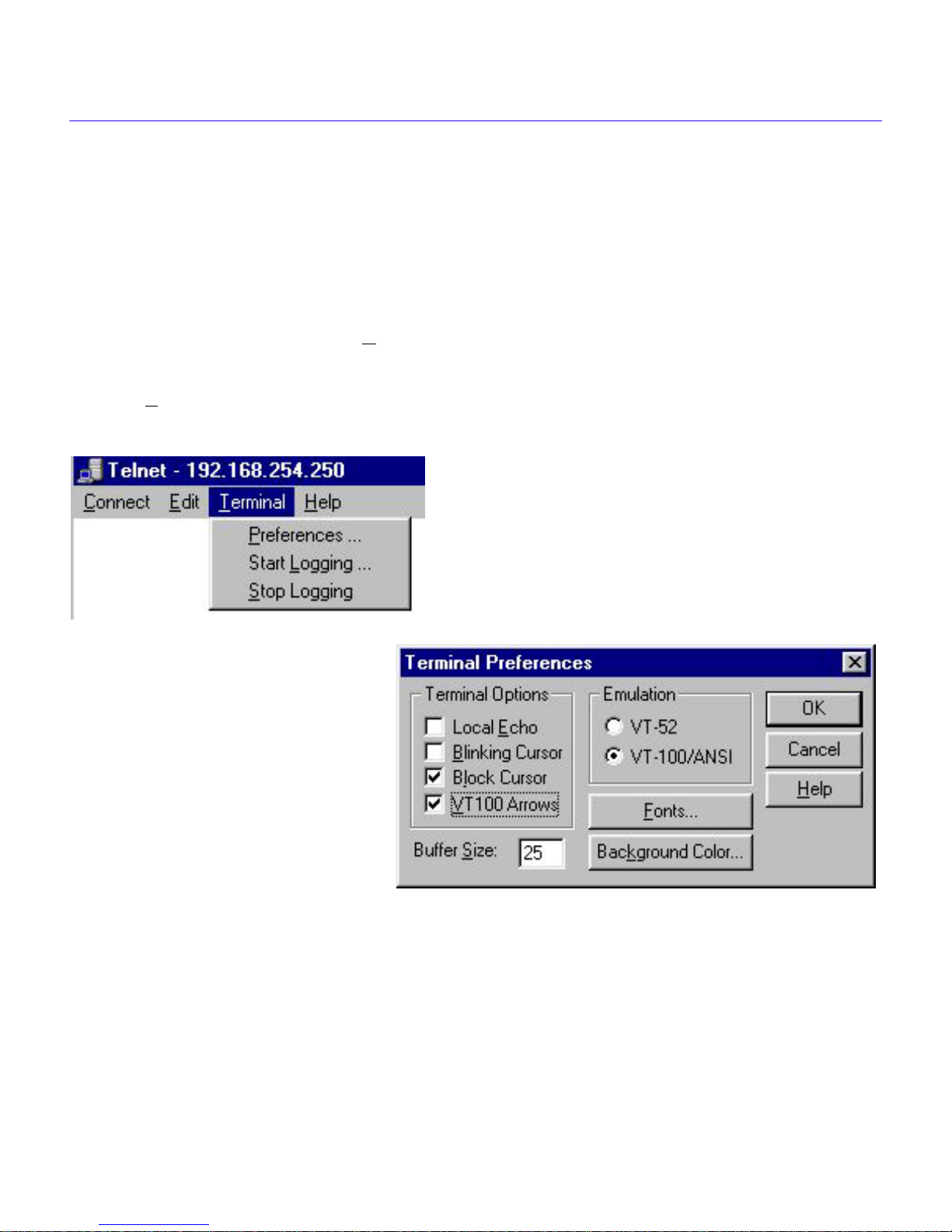
Start QuickSET and click the NEXT button on the first two windo ws. Under the File menu on the
title bar of the third window, select T
Terminal and the Terminal menu will display as shown below in Figure 1-2.
Click on Preferences in the Terminal menu, and the Terminal Preferences window will display as
shown below in Figure 1-2.
elnet. In the title bar of the first Telnet screen, click on
Figure 1-2 Terminal Menu and Terminal Preferences
Select VT100 Arr ows in the Terminal Options panel, and then select VT100/ANSI in the
emulation panel if it is not already selected. Click OK when you have finished. You are now ready
to navigate within any of the Local Management screens.
Local Management User’s Guide 1-9
Page 26

Local Management
Navigating Within Local Management Screens
To navigate within a Local Management screen, use the arrow keys of the terminal or the
workstation providing terminal emulation services. The Local Management screen cursor
responds to the LEFT-ARROW, RIGHT-ARRO W, UP-ARROW , and DO WN-ARR O W k eys. Each
time you press an arrow key, the Local Management screen cursor moves to the next a v ailable field
in the direction of the arrow key.
The Local Management screen cursor only moves to fields which can be selected or used for input.
This means that the cursor jumps over display fields and empty lines on the Local Management
screen.
The Local Management screen cursor provides wrap-around operation. This means that a cursor
located at the edge of a screen, when moved in the direction of that edge, “wraps around” to the
outermost selectable item on the opposite side of the screen which is on the same line or column.
Selecting Local Management Menu Screen Items
To select items in a Local Management menu screen, perform the following steps:
1. Use the arrow keys to highlight a menu item.
2. Press ENTER. The selected Local Management menu screen displays.
Exiting Local Management Screens
To exit any of the Local Management screens, perform the following steps:
1. Use the arrow keys to highlight the RETURN command at the bottom of the Local
Management screen.
2. Press ENTER. The previous screen in the Local Management hierarchy displays.
You can also exit Local Management screens b y pressing ESC twice. This exit method
NOTE
Exiting the Local Management Session
does not warn you about unsaved changes, and all unsaved changes will be lost.
To exit from HSIM or CyberSWITCH Local Management, perform the following steps:
1. Use the arrow keys to highlight the RETURN command at the bottom of the Local
Management screen.
2. Press ENTER. The previous screen in the Local Management hierarchy displays.
1-10 Local Management User’s Guide
Page 27

Local Management Overview
3. Repeat steps 1 and 2 until the Main Menu screen displays.
4. Use the arrow keys to highlight the EXIT command at the bottom of the Main Menu screen.
5. Press ENTER. The HSIM or CyberSWITCH Local Management Password screen displays
and the Local Management session ends.
Establishing a TELNET Connection
The HSIM or CyberSWITCH is shipped with a temporary IP Address of 192.168.254.254 so that
your computer can communicate with it over your Local Area Network (LAN) through a TELNET
connection. However, to establish a TELNET connection, your computer must be on the same
subnet as the HSIM or CyberSWITCH. Cabletron Systems recommends that you assign a
temporary IP Address of 192.168.254.253 to your computer to ensure that both devices are on the
same subnet. TELNET connections to the host device require the community name passwords
assigned at the SNMP Community Names screen or if you are doing an initial configuration, you
can use the default password public.
See the instructions included with the TELNET application for information about
NOTE
establishing a TELNET session.
Local Management Screen Hierarchy
Local Management consists of a series of menu screens that provide a path to each of the Local
Management function screens. Navigate through Local Management by selecting items from the
menu screen. Figure 1-3 shows the hierarchy of the Local Management screens.
System Level
SNMP Community Names
Password
Main Menu
Setup Menu
MIB Navigator
SNMP Traps
Flash Download
WAN Setup
Bridge Setup
Router Setup
IP
IPX
IP General Config
IP RIP
IP OSPF
IPX General Config
IPX SAP
IPX RIP
Figure 1-3 Hierarchy of Local Management Screens
Local Management User’s Guide 1-11
2012_20
Page 28

Local Management
Accessing Local Management
This section explains how to access and use the Local Management menu screens. Menu screens
provide a path to the setup screens and status screens.
Using the Menu Screens
Once you have accessed the HSIM or CyberSWITCH through a TELNET connection, the
Password screen, shown in Figure 1-4, displays.
Local Management
CABLETRON Systems, Incorporated
P.O. Box 5005
Rochester, NH 03866-5005 USA
(603) 332-9400
(c) Copyright CABLETRON Systems, Inc. 1999
Device Model Number:
Serial Number:
Functionality Level:
Flash Image Version:
BOOTPROM Version:
Board Revision:
Enter Password:
XXXXXXX
XXXX
XXX
02.XX.XX
XX.XX.XX
201201
Figure 1-4 Password Screen
Type in your password and press ENTER. If you are doing an initial configuration, you can type
the default super-user access password “public” or just press ENTER.
Your password is one of the community names specified in the SNMP Community
NOTE
Names screen. Access to certain Local Management capabilities depends on the
degree of access accorded that community name. See the SNMP Community Names
section.
1-12 Local Management User’s Guide
Page 29

Accessing Local Management
• If you enter a valid password, the associated access level displays at the bottom of the screen
and the Main Menu screen, shown in Figure 1-5, on the following page, displays.
• If you enter an inv alid password, the cursor returns to the be ginning of the password entry field.
• If no activity occurs for several minutes, the Password screen displays again, ending your
current session. You must reenter the password to perform Local Management tasks.
Main Menu Screen
The Main Menu screen is the starting point from which all the Local Management screens are
accessed. Figure 1-5, below, shows the Main Menu screen.
<host name> Local Management
Flash Image Version: 02.XX.XX
MAIN MENU
SETUP MENU
MIB NAVIGATOR
EXIT
2012_02
Figure 1-5 Main Menu Screen
The Main Menu screen displays the following menu items:
Setup Menu — The Setup Menu provides access to Local Management screens that are used to
configure the HSIM or CyberSWITCH.
Local Management User’s Guide 1-13
Page 30

Local Management
MIB Navigator — The MIB Navigator is a Local Management utility that lets you access,
monitor, and set specific Management Information Base (MIB) items within the HSIM or
CyberSWITCH.
Setup Menu Screen — The Setup Menu screen provides access to the Local Management
screens that are used to configure the HSIM or CyberSWITCH. Examples of functions accessible
through the Setup Menu include configuring the host IP address and Subnet Mask, assigning the
SNMP community names, and configuring the SNMP trap notification. Figure 1-6 shows the
Setup Menu screen.
<host name> Local Management Flash Image Version 02.XX.XX
<host name> Local Management Flash Image Version 02.XX.XX
SETUP MENU
SETUP MENU
SYSTEM LEVEL
SYSTEM LEVEL
SNMP COMMUNITY NAMES
SNMP COMMUNITY NAMES
SNMP TRAPS
SNMP TRAPS
FLASH DOWNLOAD
FLASH DOWNLOAD
WAN SETUP
WAN SETUP
BRIDGE SETUP
BRIDGE SETUP
ROUTER SETUP
ROUTER SETUP
The Setup Menu screen displays the following menu items:
System Level — The System Level screen allows you to configure basic operating parameters
for the HSIM or CyberSWITCH.
SNMP Community Names — The SNMP Community Names screen allows you to change or
review the community names used as access passwords for local management operation.
1-14 Local Management User’s Guide
Figure 1-6 Setup Menu Screen
RETURN
RETURN
2012_03
2012_03
Page 31

System Level Screen
SNMP T raps — The SNMP Traps screen pro vides display and configuration access to the table of
IP addresses used for trap destinations and associated community names.
Flash Download — The Flash Download screen lets you download a firmware image from a
TFTP server to the HSIM or CyberSWITCH.
WAN Setup
— The WAN Setup menu item accesses two other screens that provide WAN
physical configuration and WAN Interface configuration access to enable a WAN link to be set up.
Bridge Setup — The Bridge Setup screen lets you select a Spanning Tree protocol and enable/
disable switch ports.
Router Setup — The Router Setup screen accesses two other screens that provide general IP or
IPX routing configuration and allow you to enable or disable the Routing Information Protocol
(RIP) and the Service Advertising Protocol (SAP) features.
If you have a WPIM-T1, WPIM-DDS, or a WPIM-HDSL installed in your HSIM or
NOTE
CyberSWITCH, refer to the WAN Setup section of this chapter for configuration
information. For all other WPIMs, refer to your specific WPIM(s) Local Management
Guide or the Appendix for information on configuring the WPIM for a Wide Area
Network Interface.
System Level Screen
The System Level screen displays the physical address (MAC address) of the HSIM or
CyberSWITCH and allows you to set the following parameters:
• System Date
• System Time
• Host IP Address
• Subnet Mask
• Physical Address
• Default Gateway
• Default Interface
Local Management User’s Guide 1-15
Page 32

Local Management
Access the System Level screen (Figure 1-7) from the Setup Menu screen by using the arrow keys
to highlight the System Level option and pressing ENTER. The System Level screen displays.
<host name> Local Management Flash Image Version 02.XX.XX
<host name> Local Management Flash Image Version 02.XX.XX
SYSTEM LEVEL
SYSTEM LEVEL
System Date:
System Date:
Host IP Address 0.0.0.0
Host IP Address 0.0.0.0
Subnet Mask 255.255.0.0
Subnet Mask 255.255.0.0
Phys Address 00-00-1D-16-26-F8
Phys Address 00-00-1D-16-26-F8
03/25/1999
03/25/1999
SAVE RETURN
SAVE RETURN
Default Gateway NONE DEFINED
Default Gateway NONE DEFINED
Default Interface NONE DEFINED
Default Interface NONE DEFINED
14:23:00System Time:
14:23:00System Time:
2012_04
2012_04
Figure 1-7 System Level Screen
The following definitions explain each System Le v el screen field. The sections which follow these
definitions explain the use of these fields.
System Date — Use this field to enter the system date, as described in Setting the System Date.
System Time — Use this field to enter the system time, as described in Setting the System
Time.
Host IP Address — Use this field to enter the IP address of the HSIM or CyberSWITCH, as
described in Setting the Host IP Address.
1-16 Local Management User’s Guide
Page 33

System Level Screen
Subnet Mask — This field displays the default Subnet Mask, and allows you to enter a ne w v alue
for the Subnet Mask if necessary. Subnets are logical divisions of the network that isolate groups
of devices. A subnet mask “masks out” the network bits of the IP address by setting the bits in the
mask to 1 when the network treats the corresponding bits in the IP address as part of the network
or subnetwork address, or to 0 if the corresponding bit identifies the host. The default subnet mask
uses the first two portions of the IP address to identify the net id, leaving the rest of the IP address
to identify specific nodes.
• When the management workstations designated to receive SNMP traps reside on the same
network as the HSIM or CyberSWITCH, use the Subnet Mask default setting for the IP address
entered on the System Level screen.
• Set a new value for the Subnet Mask when the management w orkstations designated to recei ve
SNMP traps reside on a different subnet (for example, across a gateway or router).
To set a Subnet Mask, refer to Setting the Subnet Mask.
Phys Address — This field displays the physical address of the HSIM or CyberSWITCH. You
cannot modify the physical address.
Default Gateway — Use this field to enter the IP address for the Default Gateway, intended for
bridging only mode. For routing use a default route entry in your routing table. This field contains
the IP address of the device to which all packets addressed to an unkno wn network or host are sent.
The HSIM or CyberSWITCH relies on a Default Gateway to pro vide the routes to destinations that
are not listed in its own IP Forwarding Table, and to forward SNMP traps to a management station.
The default setting for this field is NONE DEFINED. To set the Default Gateway, refer to Setting
the Default Gateway.
Default Interface — Use this field to select the default interface for the HSIM or CyberSWITCH
Default Gateway, intended for bridging only mode. For routing use a default route entry in your
routing table. The default interface is the channel which is set up to handle SNMP traps sent to an
IP station that is not on the same subnet as the HSIM or CyberSWITCH in an IP routed
environment. The default setting for this field is NONE DEFINED. To set the default interface for
the Default Gateway of the HSIM or CyberSWITCH, refer to Setting the Default Interface.
Local Management User’s Guide 1-17
Page 34

Local Management
Setting the System Date
The HSIM or CyberSWITCH is year 2000 compliant so that the System Date field can be set
beyond the year 1999. To set the system date, perform the following steps:
1. Use the arrow keys to highlight the System Date field.
2. Enter the date in an MM/DD/YYYY format.
When entering the date in the system date field, you do not need to add separators
NOTE
3. Press ENTER to set the system date.
4. Use the arrow keys to highlight the SAVE command at the bottom of the screen and press
ENTER.
between month, day, and year numbers, as long as the entire entry uses eight decimal
numbers. For example, to set the date to 06/17/1999, type “06171999” in the System
Date field.
If the date entered was a valid format, the Event Message field at the top of the screen displays
“SAVED OK”. If the entry was not valid, Local Management does not alter the current value and
refreshes the System Date field with the previous value.
Setting the System Time
To set the system time, perform the following steps:
1. Use the arrow keys to highlight the System Time field.
2. Enter the time in a 24-hour format, HH:MM:SS.
When entering the time in the system time field, you do not need to add separators
NOTE
3. Press ENTER to set the system time.
4. Use the arrow keys to highlight the SAVE command field at the bottom of the screen and press
ENTER. If the time entered was a valid format, the Event Message field at the top of the screen
displays “SAVED OK”. If the entry was not valid, Local Management does not alter the current
value and refreshes the System Time field with the previous value.
between hours, minutes, and seconds, as long as each entry uses two decimal
numbers. For example, to set the time to 6:45 a.m., type “064500” in the System Time
field.
1-18 Local Management User’s Guide
Page 35

System Level Screen
Setting the Host IP Address
To set the host IP address, perform the following steps:
1. Use the arrow keys to highlight the Host IP Address field.
2. Enter the IP address using Decimal Dotted Notation (DDN) format.
For example: 168.192.25.17
3. Press ENTER. If the IP address entered was a valid format, the cursor returns to the beginning
of the Host IP Address field. If the entry was not valid, the Event Message field displays
“INVALID IP ADDRESS OR FORMAT ENTERED”. Local Management does not alter the
current value and refreshes the Host IP Address field with the previous value.
4. Use the arrow keys to highlight the SAVE command field.
5. Press ENTER. The Event Message field at the top of the screen displays “SAVED OK”.
Setting the Subnet Mask
Subnets are logical divisions of the network. To change the Subnet Mask from its default value,
perform the following steps:
1. Use the arrow keys to highlight the Subnet Mask field.
2. Enter the Subnet Mask using Dotted Decimal Notation (DDN) format. Values for each decimal
can be from 0 to 255.
For example: 255.255.0.0
3. Press ENTER. If the Subnet Mask entered was a valid format, the cursor returns to the
beginning of the Subnet Mask field. If the entry was not valid, the Event Message field displays
“INVALID SUBNET MASK OR FORMAT ENTERED”. Local Management does not alter
the current value and refreshes the Subnet Mask field with the previous value.
4. Use the arrow keys to highlight the SAVE command field.
5. Press ENTER. The Event Message field at the top of the screen displays “SAVED OK”.
Setting the Default Gateway
To set the Default Gateway, perform the following steps:
1. Use the arrow keys to highlight the Default Gateway field.
Local Management User’s Guide 1-19
Page 36

Local Management
2. Enter the IP address of the Default Gateway using DDN format.
For example: 168.192.79.121
3. Press ENTER. If the Default Gateway address entered was a valid format, the cursor returns to
the beginning of the Default Gateway field. If the entry was not valid, the Event Message field
displays “INVALID DEFAULT GATEWAY OR FORMAT ENTERED”. Local Management
does not alter the current value and refreshes the Default Gateway field with the previous value.
4. Use the arrow keys to highlight the SAVE command field.
5. Press ENTER. The Event Message field at the top of the screen displays “SAVED OK”.
The default gatew a y is intended f or bridging only mode. For routing use a default route
NOTE
entry in your routing table.
Setting the Default Interface
To set the default interface, perform the following steps:
1. Use the arrow keys to highlight the Default Interface field.
2. Enter the interface number for the Default Gateway in this field.
3. Press ENTER. If the interface entered was a valid format, the cursor returns to the beginning of
the Subnet Mask field. If the entry was not valid, the Event Message field displays
“PERMISSIBLE RANGE: 1...X”. Local Management does not alter the current value and
refreshes the Default Interface field with the previous value.
4. Use the arrow keys to highlight the SAVE command field.
5. Press ENTER. The Event Message field at the top of the screen displays “SAVED OK”.
Both the default gatew a y and def ault interf ace must be changed or an error results . To
NOTE
return to the default state, select NONE DEFINED for both the default gateway and
default interface selections.
The default gatew a y is intended f or bridging only mode. For routing use a default route
entry in your routing table.
1-20 Local Management User’s Guide
Page 37

SNMP Community Names Screen
SNMP Community Names Screen
This section explains how to assign community names. Community names allow you to control
Local Management access by establishing three passwords. Each password controls a different
level of access to HSIM or CyberSWITCH Local Management.
Access the SNMP Community Names screen, shown in Figure 1-8, from the Setup Menu screen
by using the arrow keys to highlight the SNMP Community Names option and pressing ENTER.
The SNMP Community Names screen displays.
<host name>Local Management Flash Image Version: 02.XX.XX
<host name>Local Management Flash Image Version: 02.XX.XX
SNMP COMMUNITY NAMES
SNMP COMMUNITY NAMES
Community Name
Community Name
public
public
public
public
public
public
SAVE RETURN
SAVE RETURN
Access Policy
Access Policy
read-only
read-only
read-write
read-write
super-user
super-user
2012_05
2012_05
Figure 1-8 SNMP Community Names Screen
Community Name Access Policy
To perform any operations on the SNMP Community Names screen, you must have used the
superuser community name at the User Password prompt when initiating the Local Management
session. The default community name for each access le vel is public. If you wish to use the default,
you can type public, or just press ENTER.
Local Management User’s Guide 1-21
Page 38

Local Management
The following explains each of the SNMP Community Names screen fields:
Community Name — Displays the user-defined names through which a user accesses the HSIM
or CyberSWITCH Local Management. Any community name entered here acts as a password to
Local Management.
Access Policy — Indicates the access status accorded each community name. Possible status
conditions are:
read-only - This access level allows reading of device parameters not including
community names.
read-write - This access level allows editing of some device configuration parameters not
including changing or viewing community names.
superuser - This access level allows full management privileges.
Setting SNMP Community Names
To set a community name, perform the following steps:
If you edit the super-user community name, be certain you do not forget it. If you do, y ou
!
CAUTION
cannot perform Local Management functions without returning the device to its factory
default configurations. This effectively erases any configuration work you have done.
1. Use the arrow keys to highlight the community name you want to change.
2. Type the new community name and press ENTER. The old community name is replaced by the
new community name.
3. Use the arrow keys to highlight the SAVE command field.
4. Press ENTER. The Event Message field at the top of the screen displays “SAVED OK”.
1-22 Local Management User’s Guide
Page 39

SNMP Traps Screen
SNMP T raps Screen
The SNMP Traps screen, shown in Figure 1-9, allows the user to configure the HSIM or
CyberSWITCH to send traps to as many as eight remote management workstations. SNMP traps
are messages about network events and device operational statistics. Access the SNMP Traps
screen from the Setup Menu screen by using the arrow keys to highlight the SNMP Traps option
and pressing ENTER. The SNMP Traps screen displays.
<host name> Local Management Flash Image Version: 02.XX.XX
SNMP TRAPS
Trap Community NameTrap Destination Enable Traps
0.0.0.0
0.0.0.0
0.0.0.0
0.0.0.0
0.0.0.0
0.0.0.0
0.0.0.0
0.0.0.0
SAVE
public
public
public
public
public
public
public
public
(NO)
(NO)
(NO)
(NO)
(NO)
(NO)
(NO)
(NO)
RETURN
201206
Figure 1-9 SNMP Traps Screen
Trap Table Screen Fields
The following definitions explain each of the SNMP Traps screen fields:
Trap Destination — Use this field to enter the IP address of the management workstation
designated to receive SNMP traps from the HSIM or CyberSWITCH.
Trap Community Name — Use this field to enter the community name of the management
workstation with the associated IP address. The community name indicates the “access level” of
traps that will be forwarded to the Trap destination.
Enable T raps — Use this field to enable the transmission of SNMP traps to the management
workstation.
Local Management User’s Guide 1-23
Page 40

Local Management
Setting the SNMP Trap Destination
Each management workstation designated to receive SNMP traps from the HSIM or
CyberSWITCH must have a valid IP address and community name. To set and enable SNMP trap
destination, perform the following steps:
1. Use the arrow keys to highlight the Trap Destination field that you want to modify.
2. Type the IP address of the management workstation designated to receive SNMP traps from the
HSIM or CyberSWITCH. This address must be entered in DDN format.
For example: 168.192.25.17
3. Press ENTER. If the IP address entered was a valid format, the cursor returns to the beginning
of the Trap Destination IP address field. If the entry was not valid, the Event Message field
displays “INVALID IP ADDRESS OR FORMAT ENTERED”. Local Management does not
alter the current value and refreshes the Trap Destination IP address field with the previous
value.
4. Use the arrow keys to highlight the Trap Community Name field (on the same row as the Trap
Destination field).
5. Type the community name of the management workstation. The community name indicates the
“access level” of traps that will be forwarded to the Trap destination.
6. Press ENTER.
7. Use the arrow keys to highlight the Enable Traps field (on the same row as the Trap
Destination and Trap Community Name you have just configured). The default setting for this
field is NO.
8. Press the SPACE bar or BACKSPACE to set the field to YES.
9. Use the arrow keys to highlight the SAVE command field.
10. Press ENTER. The Event Message field at the top of the screen displays “SAVED OK”.
11. Repeat this procedure as necessary to set each Trap Destination.
1-24 Local Management User’s Guide
Page 41

Flash Download Screen
Flash Download Screen
The Flash Download screen (Figure 1-10) allo ws you to do wnload a firmware image from a TFTP
server to the HSIM or CyberSWITCH.
Access the Flash Download screen from the Setup Menu screen by using the arrow keys to
highlight the Flash Download option and pressing ENTER. The Flash Download screen, sho wn in
Figure 1-10, displays.
Flash download operations require a properly named download file and a properly
NOTE
configured download server.
<host name> Local Management Flash Image Version: 02.XX.XX
<host name> Local Management Flash Image Version: 02.XX.XX
FLASH DOWNLOAD
FLASH DOWNLOAD
Download Method:
Download Method:
Reboot After Download:
Reboot After Download:
Last Image Server IP:
Last Image Server IP:
Last Image File Name:
Last Image File Name:
Download Server IP:
Download Server IP:
Download File Name:
Download File Name:
EXECUTE RETURN
EXECUTE RETURN
[RUNTIME]
[RUNTIME]
[YES]
[YES]
XXX.XXX.XXX.XXX
XXX.XXX.XXX.XXX
c:/tftpboot/csx400.hex
c:/tftpboot/csx400.hex
XXX.XXX.XXX.XXX
XXX.XXX.XXX.XXX
c:/tftpboot/csx400.hex
c:/tftpboot/csx400.hex
Figure 1-10 Flash Download Screen
201207
201207
Local Management User’s Guide 1-25
Page 42

Local Management
The following definitions explain each of the Flash Download screen fields.
Download Method — Use this field to select the method you wish to use to download the
firmware image to the HSIM or CyberSWITCH.
• Reboot After Download — This field displays when the RUNTIME Download Method is
chosen. Selecting YES forces the HSIM or CyberSWITCH to reboot and use the new firmw are
image immediately. Selecting NO allows the HSIM or CyberSWITCH to continue using the
existing firmware image without interrupting network operation.
• Commit to Flash — This field displays when the BOOTPROM Download Method is chosen.
Selecting YES allows the HSIM or CyberSWITCH to continue using the existing firmware
image without interrupting network operation and selecting NO allows the HSIM or
CyberSWITCH to reboot and use the new firmware image immediately.
• TFTP Gateway Server IP — This field displays when the BOOTPROM Download Method
is chosen. Use this field to enter the IP address of the TFTP Gateway Server.
Last Image Server IP — Displays the IP address of the last server used to download a firmware
image to the HSIM or CyberSWITCH.
Last Image File Name — Displays the file name of the last firmware image downloaded to the
HSIM or CyberSWITCH.
Download Server IP — Use this field to type in the IP address of the server from which you wish
to download the firmware image.
Download File Name — Use this field to type in the file name of the firmware image you wish to
download to the HSIM or CyberSWITCH.
Selecting a Flash Download Method
1. Use the arrow keys to highlight the Download Method field.
2. Press the SPACE bar or BACKSPACE to select a flash download method.
• If you select RUNTIME, the Reboot After Download field displays.
• If you select BOOTPROM, the Commit to Flash field and the TFTP Gateway Server IP
field display.
1-26 Local Management User’s Guide
Page 43

Flash Download Screen
RUNTIME Download
If you select RUNTIME Download, perform the following steps:
1. Use the arrow keys to highlight the Reboot After Download field.
2. Press the SPACE bar or BACKSPACE to select one of the following:
• YES, if you want the HSIM or CyberSWITCH to reboot and use the new firmware image
immediately.
• NO, if you want the HSIM or CyberSWITCH to continue using the existing firmware
image without interrupting network operation. The HSIM or CyberSWITCH stores the ne w
firmware image in flash memory. When you reset the HSIM or CyberSWITCH, it boots
from flash memory using the new image.
3. Use the arrow keys to highlight the Download Server IP field.
4. Type the IP address of the download server and press ENTER.
5. Use the arrow keys to highlight the Download File Name field.
6. Type the complete path and filename of the new image file to be downloaded. You must include
all directories and subdirectories involved in accessing the file. Type the new entry over the
previous entry. For example: c:\images\cyberswitch\11011.hex
7. Press ENTER.
8. Use the arrow keys to highlight the EXECUTE command located at the bottom of the Flash
Download screen.
9. Press ENTER to begin the download. The HSIM or CyberSWITCH attempts to download the
file using the IP address, filename, and path provided. This file is assigned to the Flash memory
of the HSIM or CyberSWITCH.
Local Management User’s Guide 1-27
Page 44

Local Management
BOOTPROM Download
If you select a BOOTPROM Download, perform the following steps:
1. Use the arrow keys to highlight the Commit to Flash field.
2. Press the SPACE bar or BACKSPACE to select one of the following:
• YES, if you want the HSIM or CyberSWITCH to continue using the existing firmware
image without interrupting network operation. The HSIM or CyberSWITCH stores the ne w
firmware image in flash memory. When you reset the HSIM or CyberSWITCH, it boots
from flash memory using the new image.
• NO, if you want the HSIM or CyberSWITCH to reboot and use the new firmware image
immediately.
3. Use the arrow keys to highlight the Download Server IP field.
4. Type the IP address of the download server and press ENTER.
5. Use the arrow keys to highlight the Download File Name field.
6. Type the complete path and filename of the new image file to be downloaded. You must include
all directories and subdirectories involved in accessing the file. Type the new entry over the
previous entry. For example: c:\images\cyberswitch\11011.hex.
7. Press ENTER.
8. Use the arrow keys to highlight the TFTP Gateway Server IP field.
9. Enter the IP address of the TFTP gateway server.
10. Use the arrow keys to highlight the EXECUTE command located at the bottom of the Flash
Download screen. The HSIM or CyberSWITCH attempts to download the file using the IP
address, filename, and path provided. This file is assigned to the Flash memory of the HSIM or
CyberSWITCH.
The WAN Setup portion of Local Management is detailed in Chapter 2, WAN
NOTE
Configuration.
1-28 Local Management User’s Guide
Page 45

Bridge Setup Screen
Bridge Setup Screen
The Bridge Setup screen enables you to select a Spanning T ree protocol and enable/disable bridge
ports. Access the Bridge Setup screen, shown in Figure 1-11, by using the arrow keys to highlight
the Bridge Setup option and pressing ENTER. The Bridge Setup screen displays.
<host name> Local Management Flash Image Version: 02.XX.XX
BRIDGE SETUP
SPANNING TREE PROTOCOL:
BRIDGE PORT ADMIN STATUS:
BRIDGE PORT PAIR ADMIN STATUS:
SAVE
Figure 1-11 Bridge Setup Screen
Bridge Setup Screen Fields
[IEEE 802.1]
PORT 01 --> ALL PORTS
PORT XX --> PORT [02]
BRIDGE_PORT [01]
[ENABLED]
[ENABLED]
RETURN
201208
The following list describes each of the Bridge Setup screen fields:
SP ANNING TREE PROT OCOL — Use this field to select a Spanning Tree protocol. Possible
selections for this field are IEEE 802.1, DEC, or NONE.
BRIDGE PORT ADMIN STATUS — Use this field to enable or disable individual HSIM or
CyberSWITCH bridge ports. Possible selections for this field are ENABLED or DISABLED.
BRIDGE PORT PAIR ADMIN STATUS — Use this field to enable or disable bridging between
bridge port pairs. For example, you can enable Port 1 to bridge traffic to all ports except Port 2.
BRIDGE_PORT
XX
— Use this command field to select the HSIM or CyberSWITCH bridge port
you want to configure.
Local Management User’s Guide 1-29
Page 46

Local Management
Selecting a Spanning Tree Protocol
To select the Spanning Tree protocol to be used by the HSIM or CyberSWITCH, perform the
following steps:
1. Use the arrow keys to highlight the SPANNING TREE PROTOCOL field.
2. Press the SPACE bar or BACKSPACE to select [IEEE 802.1], [DEC], or [NONE].
3. Use the arrow keys to highlight the SAVE command field.
4. Press ENTER. The Event Message field at the top of the screen displays “SAVED OK”.
Selecting the Bridge Port Administrative Status
To select the bridge port administrative status, perform the following steps:
1. Use the arrow keys to highlight the [BRIDGE_PORT XX] field at the bottom of the Bridge
Setup screen.
2. Press the SPACE bar or BACKSPACE to select the bridge port you want to configure. The
selected bridge port displays in the Bridge Port Admin Status field.
3. Use the arrow keys to highlight the BRIDGE PORT ADMIN STATUS: PORT X - - > ALL
PORTS [ENABLED] field.
4. Press the SPACE bar or BACKSPACE to select ENABLE or DISABLE.
For example, the following bridge setup indicates that bridge port 01 is configured to bridge
traffic to all ports:
BRIDGE PORT ADMIN STATUS: PORT 01 - - > ALL PORTS [ENABLED]
5. Use the arrow keys to highlight the SAVE command field.
6. Press ENTER. The Event Message field at the top of the screen displays “SAVED OK”.
1-30 Local Management User’s Guide
Page 47

Bridge Setup Screen
Selecting the Bridge Port Pair Administrative Status
To select the bridge port pair administrative status, perform the following steps:
1. Use the arrow keys to highlight the [BRIDGE_PORT XX] field at the bottom of the Bridge
Setup screen.
2. Press the SPACE bar or BACKSPACE to select the bridge port you want to configure. The
selected bridge port displays in the Bridge Port Pair Admin Status field.
3. Use the arrow keys to highlight the BRIDGE PORT PAIR ADMIN STATUS: PORT X - ->
PORT [Y] field.
4. Press the SPACE bar or BACKSPACE to select the port you want to enable or disable bridge
traffic.
5. Use the arrow keys to highlight the BRIDGE PORT PAIR ADMIN STATUS: PORT X - ->
PORT [Y] [ENABLED] field.
6. Press the SPACE bar or BACKSPACE to select ENABLE or DISABLE.
For example, the following bridge setup indicates that bridge port 01 is configured NOT to
bridge traffic to bridge port 02:
BRIDGE PORT PAIR ADMIN STATUS: PORT 01 - - > PORT [02] [DISABLED]
7. Use the arrow keys to highlight the SAVE command field.
8. Press ENTER. The Event Message field at the top of the screen displays “SAVED OK”.
Local Management User’s Guide 1-31
Page 48

Local Management
Router Setup Screen
The Router Setup menu screen allows you to choose either IP or IPX routing for your HSIM or
CyberSWITCH.
Access the Router Setup screen, shown in Figure 1-12, by using the arrow keys to highlight the
ROUTER SETUP menu item in the Setup Menu and pressing ENTER. The Router Setup menu
screen displays.
<host name> Local Management Flash Image Version 02.XX.XX
ROUTER SETUP
IP
IPX
INITIALIZE
Figure 1-12 Router Setup Screen
RETURN
IP/IPX
Router Setup Fields
The following list describes the Router Setup menu screen.
IP — Use this field to access the IP Configuration Screen to configure the HSIM or
CyberSWITCH for IP routing.
IPX — Use this field to access the IPX Configuration Screen to configure the HSIM or
CyberSWITCH for IPX routing.
INITIALIZE — The device does a soft reset to allow any setting changes to be saved, no
diagnostics are performed.
1-32 Local Management User’s Guide
Page 49

IP Configuration Screen
IP Configuration Screen
The IP Configuration menu screen enables you to access the IP General Config and IP RIP screens
to configure the HSIM or CyberSWITCH for IP Routing and enable RIP on the HSIM or
CyberSWITCH.
Access the IP Configuration menu screen, shown in Figure 1-13, by using the arrow keys to
highlight the IP menu item on the Router Setup screen and pressing ENTER. The IP Configuration
screen displays.
<host name> Local Management Flash Image Version 02.XX.XX
IP CONFIGURATION
IP General Config
IP RIP
OSPF
RETURN
201209
Figure 1-13 IP Configuration Screen
IP Configuration Screen Fields
The following list describes each of the IP Configuration screen fields.
IP General Config — Use this field to access the IP General Configuration Screen and
configure the HSIM or CyberSWITCH for IP routing.
IP RIP — Use this field to access the IP RIP screen and enable Routing Information Protocol
(RIP) routing on the HSIM or CyberSWITCH.
IP OSPF — Use this field to access the IP OSPF Configuration screen to configure and enable
OSPF for IP routing on the HSIM or CyberSWITCH.
Local Management User’s Guide 1-33
Page 50

Local Management
IP General Configuration Screen
The IP General Configuration screen allows you to configure the HSIM or CyberSWITCH for IP
routing.
Access the IP General Configuration screen by using the arrow keys to highlight the IP General
Config menu item and pressing ENTER. The IP General Configuration screen shown in
Figure 1-14 displays.
<host name> Local Management Flash Image Version 02.XX.XX
<host name> Local Management Flash Image Version 02.XX.XX
IP Router ID: XXX.XXX.XXX.XXX
IP Router ID: XXX.XXX.XXX.XXX
IP GENERAL CONFIGURATION
IP GENERAL CONFIGURATION
Router Name: IP
Router Name: IP
Version: 02.XX.XX
Version: 02.XX.XX
IP Routing: ENABLED
IP Routing: ENABLED
Redirector: FORWARD
Redirector: FORWARD
Description: Ctron CSX400 EnetPort
Port: 1
Port: 1
MAC Address: 00-00-1D-22-46-B0
MAC Address: 00-00-1D-22-46-B0
Oper Status: Enabled
Oper Status: Enabled
Address: XXX.XXX.XXX.XXX Mask: 255.255.0.0 Address Type: Primary
Address: XXX.XXX.XXX.XXX Mask: 255.255.0.0 Address Type: Primary
IP Routing: ENABLED IP Forwarding: ENABLED Proxy ARP: DISABLED
IP Routing: ENABLED IP Forwarding: ENABLED Proxy ARP: DISABLED
+PORT- +REDIRECTOR-
+PORT- +REDIRECTOR-
Description: Ctron CSX400 EnetPort
Status: Enabled
Status: Enabled
AdminStatusTime: 0 days 0 hours 39 min
AdminStatusTime: 0 days 0 hours 39 min
System Level Setup
Server: 000.000.000.000
Server: 000.000.000.000
UDP Port: 37
UDP Port: 37
Network Bcast: Ones
Network Bcast: Ones
System Level Setup
Port Level Setup
Port Level Setup
Framing: Ethernet MTU: 1500
Framing: Ethernet MTU: 1500
SAVE RETURN
SAVE RETURN
UpTime: 0 days 0 hours 39 min
UpTime: 0 days 0 hours 39 min
37 of 999
37 of 999
UDP Type: time
UDP Type: time
Interf. Type: ethernet-csmacd
Interf. Type: ethernet-csmacd
2012_11
2012_11
Figure 1-14 IP General Configuration Screen
IP General Configuration Status Fields
The following list describes each of the IP General Configuration status fields. The status fields are
for informational purposes only and cannot be modified.
Router Name — Displays the type of routing used.
Status — Displays the status of IP Routing.
UpTime — Displays the amount of time elapsed since the last time the HSIM or CyberSWITCH
was rebooted.
1-34 Local Management User’s Guide
Page 51

IP Configuration Screen
Version — Displays the IP Routing version number used on the HSIM or CyberSWITCH.
AdminStatusTime — Displays the amount of time elapsed since an IP address was assigned to
the HSIM or CyberSWITCH.
UDP T ype — Displays the User Datagram Protocol (UDP) Service to which the selected UDP
Port number corresponds.
Description — Describes the selected Port.
MAC Address — Displays the physical (MAC) address of the HSIM or CyberSWITCH.
Interf. T ype — Displays the type of interface used by the specified port.
Oper Status — Displays the operational status of the selected port.
IP General Configuration Fields
This section provides a general overview of the procedures required to configure the HSIM or
CyberSWITCH. The following describes each of the modifiable IP General Config Screen fields.
+PORT- — Use this field to select the routing port you wish to configure.
+REDIRECTOR- — Use this field to toggle through a list of commonly used UDP port numbers.
UDP port numbers are associated with the relay agent functionality of the router.
UDP Port — User Datagram Protocol (UDP) Port affected.
Framing — Use this field to select the format of the frame in which IP packets are encapsulated
for transmission.
MTU — Use this field to set the Maximum Transmission Unit (MTU).
IP Routing — Use this field to enable IP Routing Services.
IP Forwarding — Use this field to enable IP Forwarding.
Proxy ARP — Use this field to enable Proxy Address Resolution Protocol (ARP).
Address — Use this field to assign an IP address to the port that you wish to configure.
Mask — Use this field to set the Subnet Mask for the port that you wish to configure.
Local Management User’s Guide 1-35
Page 52

Local Management
Selecting a Port for Configuration
Routing Services allows you to choose the ports that you want to configure for IP routing. To select
a router port to configure for IP routing, complete the following steps:
1. Use the arrow keys to highlight the PORT option.
2. Type in the number of the port that you want to configure for IP routing and then press ENTER.
You can type in the port number, or you can use the +PORT- option at the bottom of
NOTE
the screen to scroll through the list of the ports on your device. To use the +PORT-
option, use the arrow keys to highlight the + (to go forward), or the - (to go backward),
and then press ENTER to scroll through the available ports in the direction you have
selected. You can also use the + and - keys to scroll through the available ports.
If you type in an invalid port number, the error message “PORT NUMBER IS OUT OF RANGE”
displays. Perform steps 1 and 2 again.
Entering the IP Address and Subnet Mask
All IP hosts must have an IP Address for each network interface. These addresses identify each
network connection.
To enter the IP address for a router port, complete the following steps:
1. Use the arrow keys to highlight the ADDRESS option.
2. Type in the IP address and then press ENTER.
Once an IP address is entered, the default Subnet Mask automatically enters into the Mask field. To
to change the default Subnet Mask for a router port, complete the following steps:
1. Use the arrow keys to highlight the MASK option.
2. Type in the Subnet Mask for the IP address that you have assigned.
Selecting the Frame Type for a Port
On each port, Frame Type specifies the format of the frame in which IP packets are encapsulated
for transmission. The Frame Type options available for each router port are dependent on the type
of media supported by that router port. The choices are: Ethernet, SN AP, i8022, Nov ell, Localtalk,
Native-wan, Encap-enet, Encap-enet-8022, Encap-enet-snap, Encap-enet-novell,
Encap-tokenring-8022, Encap-tokenring-snap, Encap-fddi-8022, Encap-fddi-snap, Other.
Select the Frame Type based on your implementation, for example: Native-wan for router to router
communication, and Encap-enet or Encap-enet-snap can be chosen for either router to bridge, or
bridge to bridge communication.
1-36 Local Management User’s Guide
Page 53

IP Configuration Screen
To select the Frame Type for a port, complete the following steps:
1. Use the arrow keys to highlight the Framing option.
2. Use the ENTER key to toggle the entry to the correct Frame Type for the port.
3. Use the arrow keys to highlight the SAVE command field at the bottom of the screen and then
press ENTER. The message “SAVED OK” displays.
Setting the Maximum Transmission Unit (MTU)
The Maximum Transmission Unit specifies the maximum packet size for all IP packets that are
transmitted.
To select the MTU for a port, complete the following steps:
1. Use the arrow keys to highlight the MTU option under Port Level Setup.
2. Enter an MTU value for the media used.
3. Use the arrow keys to highlight the SAVE command field at the bottom of the screen, then press
ENTER. The message “SAVED OK” displays.
Enabling IP Routing Services on a Port
The ability to switch IP Routing Services on and off on a port-by-port basis, provides great
flexibility. On the same device, some ports can be routing IP traffic while other ports are bridging
it. As you are in transition from a bridged network to a routed network, this flexibility allows you
to implement IP routing and test your routing configuration on a port-by-port basis. If necessary,
you can temporarily disable the IP routing on any port without losing your configuration, or you
can temporarily switch from IP routing back to bridging.
To enable IP Routing Services on a router port, complete the following steps:
1. Use the arrow keys to highlight the IP Routing option under Port Level Setup.
2. Use the ENTER key to toggle the entry to ENABLED.
3. Use the arrow keys to highlight the SAVE command field at the bottom of the screen, and then
press ENTER. The message “SAVED OK” displays.
Local Management User’s Guide 1-37
Page 54

Local Management
Enabling IP Forwarding on a Port
By default, IP Forwarding is disabled on each router port. Your device cannot begin forwarding IP
data packets on any router port until you enable IP Forwarding on that port.
To enable IP Forwarding on a router port, complete the following steps:
1. Use the arrow keys to highlight the IP Forwarding option.
2. Use the ENTER key to toggle the entry to ENABLED.
3. Use the arrow keys to highlight the SAVE command field at the bottom of the screen and then
press ENTER. The message “SAVED OK” displays.
Configuring the UDP Broadcast Redirector
To locate a server that can provide a particular network service, many IP hosts rely on the use of
LAN broadcasts to send UDP service requests. The UDP port number contained in the broadcast
request packet identifies the service being requested. Table 1-4 shows the port numbers and their
corresponding requested services.
Table 1-4 UDP Port Numbers
UDP Port # UDP Services
37 Time
42 Host Name Server
53 Domain Name Server
65 TACACS-Database Service
67 Bootstrap Protocol/Dynamic Host Control Protocol Server
68 Bootstrap Protocol/Dynamic Host Control Protocol Client
69 Trivial File Transfer
137 NETBIOS Name Server
138 NETBIOS Datagram Server
111 Sunrpc (NIS)
1-38 Local Management User’s Guide
Page 55

IP Configuration Screen
The UDP Broadcast Redirector enables you to configure any Routing Services enabled device to
forward the UDP packets that it receives as LAN broadcasts, directly to the appropriate server.
UDP service requests that are sent as LAN broadcasts by clients of applications such as Host
Name, Domain Name, and Bootstrap servers, can be redirected to any server on any network
segment.
To configure the UDP Broadcast Redirector, complete the following steps:
1. Use the arrow keys to highlight the UDP Port option under System Level Setup.
2. Enter the UDP port number of the UDP service request packets that you want to redirect (refer
to Table 1-4) and then press ENTER.
3. Use the arrow keys to highlight the SAVE command field at the bottom of the screen and then
press ENTER. The message “SAVED OK” displays.
You can type in the UDP port number, or you can use the +REDIRECTOR- option at
NOTE
the bottom of the screen to scroll through a list of commonly used UDP port numbers.
To use the +REDIRECTOR- option, use the arrow keys to highlight the + (to go
forward), or the - (to go backward), and then press the ENTER key to scroll in the
direction that you selected.
The entry for the UDP Port option reflects the UDP port number that is currently selected. The
entry for UDP Type names the UDP service to which that port number corresponds.
Enabling Proxy ARP on a Port
By default, Proxy Address Resolution Protocol (ARP) is disabled on all ports, and IP Routing
Services respond only to ARP requests addressed to its own IP address.
For one IP host to communicate with another IP host, knowledge of the tar get host’s MAC address
must be known. To learn this MAC address, the IP host sends an ARP request packet as a LAN
broadcast with the destination IP address of the target IP host. All hosts receive this broadcast and
the one host that matches the target IP address responds with its MAC-layer address.
However, because each subnet constitutes a separate broadcast domain and LAN broadcasts are
not forwarded across routers, ARP does not work beyond a host’s local network or subnetwork.
One of the primary purposes of a router is to confine LAN broadcast traffic to each local network
or subnetwork.
Local Management User’s Guide 1-39
Page 56

Local Management
A proxy ARP response is generated when the following occurs:
• Proxy ARP is enabled on a router port.
• An ARP request is received as a LAN broadcast (looking for the MAC-layer address of an IP
host on another network segment).
• An entry exists in the IP Forwarding Table for the destination host’s network.
Enabling Proxy ARP on a router port allows IP hosts to dynamically obtain the MA C-layer address
of other IP hosts attached to different networks or subnetworks by using broadcast ARP request
packets. With Proxy ARP enabled, IP hosts are not required to maintain knowledge of specific
subnetworks.
To enable Proxy ARP on a router port, complete the following steps:
1. Use the arrow keys to highlight the Proxy ARP option.
2. Use the ENTER key to toggle the entry to ENABLED.
3. Use the arrow keys to highlight the SAVE command field at the bottom of the screen, and then
press ENTER. The message “SAVED OK” displays.
Configuring the Network Broadcast Type on a Port
IP Routing Services recognizes and accepts network broadcasts, IP packets with the host portion
of the IP address as either all 1’s or all 0’s. Other networking devices only recognize all 0’s as a
network broadcast.
To configure IP Routing Services to send network broadcasts addressed to all 0’s, complete the
following steps:
1. Use the arrow keys to highlight the Network Bcast option.
2. Use the ENTER key to toggle the entry to ZEROS.
3. Use the arrow keys to highlight the SAVE command field at the bottom of the screen and then
press ENTER. The message “SAVED OK” displays.
IP RIP
Routing Information Protocol (RIP) is a widely implemented routing protocol that is used
extensively on IP internetworks. IP Routing Services uses the RIP routing protocol to send and
gather information about the internetwork topology. This information is used to construct and
maintain a database called RIP Route Table, which contains the addresses of the available routes to
all the networks and hosts that RIP has learned.
1-40 Local Management User’s Guide
Page 57

IP Configuration Screen
Enabling the RIP routing protocol allows IP Routing Services to build and maintain a dynamic
database of route information. The best routes learned by the RIP routing protocol are added to the
IP Forwarding Table to forward IP packets. The ability to switch the RIP routing protocol on and
off on a port-by-port basis provides great fle xibility. On the same device, some router ports can be
running the RIP routing protocol while other router ports are not. If necessary , you can temporarily
disable the RIP routing protocol on any port without affecting the rest of your configuration.
RIP-2
The following definitions compare and contrast some of the features of the RIP-1 and RIP-2
protocols.
RIP-1 vs. RIP-2 — A comparison of the features of RIP-1 and RIP-2 protocols (excerpted from
RFC 1722, and RFC 2080) follows:
RIP-2 is essentially an extension of RIP-1; it is not a new protocol. It is a superset of the
environments in which RIP-1 has been traditionally used. It should be noted that RIP-2 is not
intended to be a substitute for OSPF (Open Shortest Path First) protocol in large autonomous
systems. The restrictions on autonomous system diameter and complexity which applied to RIP-1
also apply to RIP-2.
Subnet Masks — RIP-2 allows the smaller, simpler, distance-vector protocol to be used in
environments that require authentication or the use of variable length subnet masks, but are not of
a size or complexity that requires the use of the larger, more complex link-state OSPF protocol.
The original impetus behind the creation of RIP-2 was the desire to include subnet masks in the
routing information exchanged by RIP, as this was not included in the original definition of RIP. As
long as the subnet mask was fixed for a network, and well kno wn by all the nodes on that netw ork,
a heuristic could be used to determine if a route was a subnet route or a host route.
The inclusion of the subnet mask in RIP-2 effectively creates a 64-bit address, which eliminates
the network, subnet, and host distinction. Therefore the inclusion of a subnet mask in RIP-2 allo ws
it to be used in an autonomous system which requires precise knowledge of the subnet mask for a
given route, but does not otherwise require OSPF protocol.
Next Hop — Entries in RIP-2 routing tables always have a Next Hop field. The Next Hop is the
IPv6address of the next router along the path to the destination. The purpose of the Next Hop in
the routing table is to prevent packets from being routed through extra hops in the system. The
limitation of a maximum network diameter of 15 hops for the Next Hop field is common to both
RIP-1 and RIP-2. This statement of the limit assumes that a cost of 1 is used for each network (see
Metrics, below).
Local Management User’s Guide 1-41
Page 58

Local Management
Metrics — The RIP-1 and RIP-2 protocols use fixed “metrics” to compare alternativ e routes. This
is not appropriate where routes need to be chosen based on real-time parameters such as measured
delay, reliability, or load. RIP is intended to allow routers to exchange information for computing
routes through an IPv6-based network. Any router that uses RIP is assumed to have interfaces to
one or more networks, otherwise it isn’t a router. These are referred to as directly connected
networks.
The RIP protocol relies on access to certain information about each of these networks, the most
important of which is its metric. This metric represents the total “cost” of getting a datagram from
the router to that destination.
The routing table has the entries listed below for each destination that is reachable:
• The IPv6 prefix of the destination
• A metric, described above
• The IPv6 address of the next router along the path (the Next Hop)
• A flag to indicate the information about the route has changed recently
• Various timers associated with the route
Split Horizon — Split Horizon is an algorithm for avoiding problems caused by including routes
in the updates sent to the gateway from which they were learned. The basic split horizon algorithm
omits routes learned from one neighbor in updates sent to that neighbor.
Authentication — Authentication is a function of RIP-2 protocol only. It is not usually important
to conceal the information in the routing messages, but it is essential to prevent the insertion of
bogus routing information into the routers. Authentication prevents someone who cannot directly
access the network (i.e., someone who cannot sniff the packets to determine the password) from
inserting bogus routing information. Currently the authentication type is simple password and
MD5.
Multicasting — The RIP-2 protocol provides for the IP multicasting of periodic advertisements.
This feature was added to RIP-2 to decrease the load on systems that do not support RIP-2. It also
provides a mechanism whereby RIP-1 routers will never receive RIP-2 routes. This feature is
useful when the correct use of an advertised route depends on knowing the precise subnet mask,
which would be ignored by a RIP-1 router.
1-42 Local Management User’s Guide
Page 59

IP Configuration Screen
Compatibility Switch — A compatibility switch is necessary for two reasons. First, there are
implementations of RIP-1 in the field that do not follow RFC1058, and second, the use of
multicasting would prevent RIP-1 systems from receiving RIP-2 updates (which may be a desired
feature in some cases). This switch is configurable on a “per-interface” basis.
The switch has four send settings:
• RIP-1, in which only RIP-1 messages are sent (and received)
• RIP-1 Compatible, in which RIP-2 messages are broadcast
• RIP-2, in which RIP-2 messages are multicast
• DON’T SEND, which disables the sending of all RIP messages
The receive control has four settings:
• RIP1, only accept RIP-1 messages
• RIP2, only accept RIP-2 messages
• RIP1/RIP2, accept both RIP-1 and RIP-2 messages
• DON’T RCV, do not accept any type of RIP messages
This control is also configurable on a “per-interface” basis.
If the router is not configured to authenticate RIP-2 messages, then RIP-1 and unauthenticated
RIP-2 messages will be accepted. Authenticated RIP-2 messages will be discarded. If the router is
configured to authenticate RIP-2 messages, then RIP-1 messages and RIP-2 messages which pass
authentication testing will be accepted. Unauthenticated and failed authentication RIP-2 messages
shall be discarded.
Local Management User’s Guide 1-43
Page 60

Local Management
<host name> Local Management Flash Image Version: 2.XX.XX
IP Router ID: XXX.XXX.XXX.XXX
IP RIP CONFIGURATION
IP Address: XXX.XXX.XXX.XXX
Port: 1
System Level RIP: DISABLED
+PORT- SAVE RETURN
Port Level RIP: DISABLED
RIP send info:
RIP receive info:
RIP 2 auth type:
RIP 2 auth string:
Figure 1-15 IP RIP Configuration Screen
To enable RIP Routing, complete the following steps:
1. From the IP Configuration screen, highlight IP RIP and then press ENTER.
The IP RIP Configuration screen, shown in Figure 1-15, displays.
2. Use the arrow keys to highlight the System Level RIP option.
3. Use the ENTER key to toggle the entry to ENABLED.
4. Use the arrow keys to highlight the Port Level RIP option.
5. Use the ENTER key to toggle the entry to ENABLED.
6. Use the arrow keys to highlight the SAVE command field at the bottom of the screen, and then
press ENTER. The message “SAVED OK” displays.
7. Exit back out to the Router Setup screen, use the arrow keys to highlight the INITIALIZE
command, and use the ENTER key to initialize the device. The connection to Local
Management will disconnect and re-entry is necessary for any further configuration.
Access the IP RIP Configuration screen as before in order to continue configuration.
8. Use the arrow keys to highlight the RIP send info option.
1-44 Local Management User’s Guide
Page 61

IP Configuration Screen
9. Use the ENTER key to toggle the entry. RIP1 is the default, the other choices are RIP2,
DON’T SEND, and RIP1 COMPATIBLE. Make the proper selection for your network.
10. Use the arrow keys to highlight the RIP receive info option.
11. Use the ENTER key to toggle the entry. RIP1 is the default, and the other choices are RIP2,
RIP1/RIP2, and DON’T RCV.
12. Use the arrow keys to highlight the RIP2 auth type option.
13. Use the ENTER key to toggle the entry. NONE is the default, and the other choices are
PASSWORD and MD5.
14. If PASSWORD or MD5 is chosen, the next selection is the user defined choice of the password
in the RIP2 auth string field. Use the arrow keys the highlight the RIP2 auth string field.
15. The password, up to 16 characters in length, may be entered here.
16. The +PORT- command can be used to go to the next available port, when there is a port
configured. Use the SPACE bar to advance to the next port for configuration. Repeat the entire
procedure as above in order to configure the new selected port.
IP OSPF Configuration
OSPF (Open Shortest Path First) is a Link-State Protocol. OSPF distributes routing information
between routers belonging to a single Autonomous System (AS). In an Autonomous System,
routers exchange routing information through a common routing protocol.
An Autonomous System may contain one or more networks, but each network within the AS may
or may not support subnetting. Every OSPF routing domain must have a “Backbone”. An OSPF
backbone distributes routing information between areas in an OSPF routing domain. The
backbone of an OSPF routing domain is an OSPF area possessing an area ID of 0.0.0.0. Because
OSPF protocol only broadcasts link state updates when topology has changed, it is considered
“quiet” when compared to RIP protocol, which has to periodically send a portion, or all of its
routing table to its neighbors.
Conv ergence (the time it takes to recalculate routing tables) under OSPF protocol is instantaneous
and not periodic because of the use of IP Multicast to send the link-state updates. Updates are only
sent when routing changes occur instead of periodically, ensuring better use of available
bandwidth.
OSPF employs “flooding” to exchange link-states with other routers. Any change in routing
information is flooded to all routers in the network. The use of “areas” puts a boundary on the
explosion of link-state updates. All routers within an area will have the exact link-state database.
Local Management User’s Guide 1-45
Page 62

Local Management
<host name> Local Management Flash Image Version: 02.XX.XX
IP Router ID: XXX.XXX.XXX.XXX
IP OSPF
OSPF: DISABLED
------OSPF Area Setup-----Area ID: 0.0.0.0 Import As Extern: true
------OSPF Port Level Setup----Admin Status: ENABLED Port: 1 IP Address: XXX.XXX.XXX.XXX
I/F Area ID: 0.0.0.0 Type: broadcast
Router Priority: 1 Transit Delay: 1 Poll Interval: 120
Retrans Interval: 5 Hello Interval: 10 Router Dead Intvl: 40
Auth Key Type: none
Active Auth Key: none Auth Key(2): none
Auth Key ID: Auth Key(2) ID:
State: down
Designated Rtr: 0.0.0.0 Backup Designated Rtr: 0.0.0.0
+PORT- KEY2 ACTIVE SAVE RETURN
ipospf
Figure 1-16 IP OSPF Configuration Screen
To enable OSPF complete the following steps:
1. From the Router Select screen, select IP and press ENTER. The IP Configuration screen
displays.
2. From the IP Configuration screen, use the arrow keys to select IP OSPF. Press ENTER, and
the IP OSPF Configuration screen shown in Figure 1-16, displays.
3. Use the arrow keys to select OSPF: Disabled. Press ENTER. The selection will toggle to
Enabled.
4. Use the arrow keys to select Area ID: 0.0.0.0. Enter the Area ID number in dotted decimal
format (000.000.000.000). When you have finished entering the area ID number, use the arrow
keys to select Admin Status:. If Admin Status is Disabled, press ENTER to toggle the status
to Enabled. Use the arrow keys to select Port:. Type the port number you wish to use. Press
ENTER, and the port will be changed to the number that you typed.
1-46 Local Management User’s Guide
Page 63

IP Configuration Screen
5. Use the arrow keys to select I/F Area ID. Enter the I/F Area ID in dotted decimal notation
(000.000.000.000). When you have finished, use the arrow keys to select Router Priority.
6. Type in the number representing the router priority you desire. When you have finished, use the
arrow keys to select Retrans Interval. Enter the number of seconds of delay between
retransmission of link-state advertisements. When you have finished, use the arrow keys to
select Transmit Delay.
7. Type the number of seconds you wish to set for transmit delay. Transmit delay represents the
estimated number of seconds it takes to transmit a link-state update packet over this interface.
Link-state advertisements contained in the Link-state update packet will have their age
incremented by this amount before transmission. This value must take into account
transmission and propagation delays. When you have finished, use the arrow keys to select
Hello Interval.
8. Type the number of seconds that you wish to use for the Hello Interval. The Hello Interval is
the length of time in seconds between Hello packets that the router sends on this interface,
advertised in Hello packets sent out of this interface. When you have finished use the arrow
keys to select Poll Interval.
9. Type the number of seconds that you wish to use for Poll Interval. If a neighboring router has
become inactive (Hello packets have not been sent for [router dead] seconds, it may be
necessary to send Hello packets to the dead neighbor. The packets will be sent at a reduced rate
[Poll Interval}, which should be much larger than the Hello Interval. A typical Poll Interval for
an X.25 network is 120 seconds. When you have finished, use the arrow keys to select Router
Dead Interval.
10. Type the number of seconds that you wish to use for Router Dead Interval. Router Dead Interval
is the number of seconds before the router’s neighbors will declare it down, when they stop
hearing the router’s Hello packets. When you have finished entering the Router Dead Interval,
use the arrow keys to select SAVE. Press ENTER. The event message field at the top of the
screen displays “SAVED OK”.
Local Management User’s Guide 1-47
Page 64

Local Management
IPX Configuration Screen
The IPX Configuration screen enables you to access the IPX General Config, IPX RIP, and IPX
SAP screens to configure the HSIM or CyberSWITCH for IPX Routing and enable RIP routing or
Source Advertisement Protocol (SAP) routing on the HSIM or CyberSWITCH.
Access the IPX Configuration screen, shown in Figure 1-17, by using the arrow keys to highlight
the IPX menu item on the Router Setup and pressing ENTER. The IPX Configuration screen
displays.
<host name> Local Management Flash Image Version 2.XX.XX
Figure 1-17 IPX Configuration Screen
IPX Router ID: 0.0.0.0
IPX CONFIGURATION
IPX General Config
IPX SAP
IPX RIP
RETURN
IPX Configuration Fields
The following list describes each of the IPX Configuration screen fields.
IPX General Config — Use this field to access the IPX General Config screen and configure the
HSIM or CyberSWITCH for IP routing.
IPX SAP — Use this field to access the IPX SAP screen and enable Source Advertisement
Protocol (SAP) routing.
IPX RIP — Use this field to access the IPX RIP screen and enable the Routing Information
Protocol (RIP).
1-48 Local Management User’s Guide
Page 65

IPX Configuration Screen
IPX General Configuration Screen
The IPX General Configuration screen allows you to configure the HSIM or CyberSWITCH for
IPX routing.
To access the IPX General Configuration screen, use the arrow keys to highlight the IPX General
Config menu item and press ENTER. The IPX General Configuration screen shown in
Figure 1-18 displays.
<host name> Local Management Flash Image Version 02.XX.XX
<host name> Local Management Flash Image Version 02.XX.XX
Router Name: IPX
Version: XX.XX.XX
Router Name: IPX
Version: XX.XX.XX
IPX Routing:ENABLED
Port: 1
IPX Routing:ENABLED
MAC Address: 00-00-1D-22-46-B0
Oper Status: Enabled
Port: 1
IPX Address:
MAC Address: 00-00-1D-22-46-B0
Oper Status: Enabled
IPX Address:
+PORT-
+PORT-
Description: Ctron CSX400 EnetPort 1
Description: Ctron CSX400 EnetPort 1
IPX Routing: DISABLED
IPX Routing: DISABLED
IPX General Configuration
IPX General Configuration
Status: Enabled
AdminStatusTime: 0 days 0 hours 39 min
Status: Enabled
AdminStatusTime: 0 days 0 hours 39 min
MTU: 1500
MTU: 1500
System Level Setup
Port Level Setup
System Level Setup
Port Level Setup
Interf. Type: ethernet-csmacd
Interf. Type: ethernet-csmacd
SAVE RETURN
SAVE RETURN
UpTime: 0 days 0 hours 39 min
UpTime: 0 days 0 hours 39 min
Framing: Novell
Framing: Novell
IPX Forwarding: DISABLED
IPX Forwarding: DISABLED
Figure 1-18 IPX General Configuration Screen
IPX General Configuration Status Fields
The following list describes each of the IPX General Config status fields. The status fields are for
informational purposes only and cannot be modified.
Router Name — Displays the type of routing used.
Status — Displays the status of IPX Routing.
UpTime — Displays the amount of time elapsed since the last time the HSIM or CyberSWITCH
was rebooted.
Local Management User’s Guide 1-49
Page 66

Local Management
Version — The version number of the IP Routing used on the HSIM or CyberSWITCH.
AdminStatusTime — Displays the amount of time elapsed since an IP address was assigned to
the HSIM or CyberSWITCH.
Description — Describes the selected Port.
MAC Address — Displays the physical (MAC) address of the HSIM or CyberSWITCH.
Interf. T ype — Displays the type of interface used by the specified port.
Oper Status — Displays the operational status of the selected port.
IPX General Configuration Fields
This section provides a general overview of the procedures required to configure the HSIM or
CyberSWITCH. The following list describes each of the IPX General Config fields.
+PORT- — Use this field to select the routing port that you wish to configure.
Framing — Use this field to select the format of the Frame in which IPX packets are
encapsulated for transmission.
MTU — Use this field to set the Maximum Transmission Unit (MTU).
IPX Routing — Use this field to enable IPX Routing Services.
IPX Forwarding — Use this field to enable IPX Forwarding.
IPX Address — Use this field to assign an IPX Address to the port that you wish to configure.
Selecting a Port for Configuration
Routing Services allows you to choose the ports that you want to configure for IPX routing. To
select a router port to configure for IPX routing, complete the following steps:
1. Use the arrow keys to highlight the PORT option.
2. Type in the number of the port that you want to configure for IPX routing, then press ENTER.
1-50 Local Management User’s Guide
Page 67

IPX Configuration Screen
You can type in the port number, or you can use the +PORT- option at the bottom of
NOTE
the screen to scroll through the list of the ports on your device. To use the +PORT-
option, use the arrow keys to highlight the + (to go forward), or the - (to go backward),
and then press ENTER to scroll through the available ports in the direction you have
selected. You can also use the + and - keys to scroll through the available ports.
If you type in an invalid port number the error message: “PORT NUMBER IS OUT OF RANGE”
displays. Perform steps 1 and 2 again.
Entering the IPX Address
All IPX hosts must have an IPX Address for each network interface. These addresses identify each
network connection.
To enter the IPX Address for a router port, complete the following steps:
1. Use the arrow keys to highlight the IPX ADDRESS option.
2. Type in the IPX Address in Dotted Decimal Notation (DDN) format and then press ENTER.
Selecting the Frame Type for a Port
On each port, Frame Type specifies the format of the frame in which IPX packets are encapsulated
for transmission. The Frame Type options available for each router port are dependent on the type
of media supported by that router port. Select the Frame Type based on your implementation, such
as Encap-enet for bridging and Native-wan for routing. The choices are: Ethernet, SNAP,
i8022,Slip, Novell, Localtalk, Native-wan, Encap-enet, Encap-enet-8022, Encap-enet-snap,
Encap-enet-novell, Encap-tokenring-8022, Encap-tokenring-snap, Encap-fddi-8022,
Encap-fddi-snap, Other.
To select the Frame Type for a port, complete the following steps:
1. Use the arrow keys to highlight the Framing option.
2. Use the ENTER key to toggle the entry to the correct Frame Type for the port.
3. Use the arrow keys to highlight the SAVE command field at the bottom of the screen and then
press ENTER. The message “SAVED OK” displays.
Local Management User’s Guide 1-51
Page 68

Local Management
Setting the Maximum Transmission Unit (MTU)
The Maximum Transmission Unit specifies the maximum packet size for all IPX packets that are
transmitted.
To select the MTU for a port, complete the following steps:
1. Use the arrow keys to highlight the MTU option under Port Level Setup.
2. Enter an MTU value for the media used.
3. Use the arrow keys to highlight the SAVE command field at the bottom of the screen and then
press ENTER. The message “SAVED OK” displays.
Enabling IPX Routing Services on a Port
The ability to switch IPX Routing Services on and off on a port-by-port basis provides great
flexibility . On the same de vice, some ports can be routing IPX traf fic while other ports are bridging
it. As you are in transition from a bridged network to a routed network, this flexibility allows you
to implement IPX routing and test your routing configuration on a port-by-port basis. If necessary ,
you can temporarily disable IPX routing on any port without losing your configuration, or you can
temporarily switch from IPX routing back to bridging.
To enable IPX Routing Services on a router port, complete the following steps:
1. Use the arrow keys to highlight the IPX Routing option under Port Level Setup.
2. Use the ENTER key to toggle the entry to ENABLED.
3. Use the arrow keys to highlight the SAVE command field at the bottom of the screen and then
press ENTER. The message “SAVED OK” displays.
Enabling IPX Forwarding on a Port
By default, IPX Forwarding is disabled on each router port. Your device cannot begin forwarding
IPX data packets on any router port until you enable IPX Forwarding on that port.
To enable IPX Forwarding on a router port, complete the following steps:
1. Use the arrow keys to highlight the IPX Forwarding option.
2. Use the ENTER key to toggle the entry to ENABLED.
3. Use the arrow keys to highlight the SAVE command field at the bottom of the screen and then
press ENTER. The message “SAVED OK” displays.
1-52 Local Management User’s Guide
Page 69

IPX Configuration Screen
IPX Routing over Frame Relay
An additional step is required when routing IPX over Frame Relay. This step requires that entries
are created in the IPX Host Map. The IPX Host Map is a database of remote IPX hosts that are
defined generally by the WAN Network number and MAC Address, and more specifically by the
Interface Number and Data Link Connection Identifier (DLCI). The IPX Host Map helps a routing
decision by determining which circuit a packet should be forwarded to in a point to multi-point
Frame Relay connection.
Figure 1-19 shows how IPX Host Map entries are entered using the circuitmap command. The
circuitmap command is accessed from the MIB Navigator Screen. Refer to Chapter 2 for more
information on the circuitmap command.
MIBNav-> circuitmap -s IPX 2 00000172 00:00:1d:02:d1:7a 102
# Interface
# 2
Network
00000172
Figure 1-19 Circuitmap Command
Node
00:00:1d:23:a1:5b
Circuit ID
102
circuitmap
The circuitmap command contains the following fields:
# Interface — An entry must be created for each remote Router connected via the Frame Relay
interface.
Network — The Network is the IPX Network number associated with the Frame Relay network.
Node — The Node is the MAC address of the remote router on the other end of the WAN link.
Circuit ID — The Circuit ID is the DLCI identifying the virtual circuit connection to the Telco.
Local Management User’s Guide 1-53
Page 70

Local Management
Enabling the IPX SAP Routing Protocol on a Port
IPX Source Advertisement Protocol (SAP) is used by IPX to exchange information about Novell
service providing nodes, such as file servers and print servers that are available. IPX SAP builds
and maintains a database, the Service Advertisement Table, containing the addresses and routes to
specific service providing nodes, and advertises this information over the network.
Each router running IPX SAP gathers this LAN based information from the locally connected
network segments and adds it to its Service Advertisement Table. Each table contains the Novell
Network Number and type of services available on all Novell servers known to the IPX SAP. IPX
routing services uses this information to provide internetworked NetWare clients with access to
these services.
To enable SAP Routing, complete the following steps:
1. From the IPX Configuration screen, highlight IPX SAP and then press ENTER.
The IPX SAP Configuration screen, shown in Figure 1-20, displays.
<host name> Local Management Flash Image Version 02.XX.XX
IPX Address: xxx.xxx.xxx.xxx
Port: 1
IPX Router ID: 0.0.0.0
IPX SAP CONFIGURATION
System Level SAP:
Port Level SAP:
SAVE+PORT-
ENABLED
ENABLED
RETURN
Figure 1-20 IPX SAP Configuration Screen
1-54 Local Management User’s Guide
Page 71

IPX Configuration Screen
2. Use the arrow keys to highlight the Port option.
3. Type in the number of the port that you wish to enable SAP routing, then press ENTER.
4. Use the arrow keys to highlight the Port Level SAP option.
5. Use the ENTER key to toggle the entry to ENABLED. Use the arrow keys to highlight the
SAVE command field at the bottom of the screen, and then press ENTER. The message
“SAVED OK” displays.
Enabling RIP on a Port
IPX RIP (Routing Information Protocol) is a widely implemented routing protocol that is used
extensively on IPX intermediations. IPX Routing Services uses the RIP to send and gather
information about the internetwork topology. This information is used to construct and maintain a
database, called the RIP Route Table, containing the addresses and available routes to all the
networks and hosts that RIP has learned.
Enabling RIP allows IPX Routing Services to build and maintain a dynamic database of route
information. The best routes learned by RIP are added to the IPX Forwarding Table to be used to
forward IPX packets. The ability to switch RIP on and off on a port-by-port basis provides great
flexibility. On the same device, some router ports can be running RIP while other router ports are
not. If necessary, you can temporarily disable RIP on any port without affecting the rest of your
configuration.
To enable RIP Routing, complete the following steps:
1. From the IPX Configuration screen, highlight IPX RIP and then press ENTER. The IPX RIP
Configuration screen, shown in Figure 1-21, displays.
Local Management User’s Guide 1-55
Page 72

Local Management
<host name> Local Management Flash Image Version 02.XX.XX
IPX Address: xxx.xxx.xxx.xxx
Port: 1
IPX Router ID: 0.0.0.0
IPX RIP CONFIGURATION
System Level RIP:
Port Level RIP:
DISABLED
DISABLED
RETURNSAVE+PORT-
Figure 1-21 IPX RIP Configuration Screen
2. Use the arrow keys to highlight the Port option.
3. Type in the number of the port that you wish to enable RIP routing and then press ENTER.
4. Use the arrow keys to highlight the Port Level RIP option.
5. Use the ENTER key to toggle the entry to ENABLED. Use the arrow keys to highlight the
SAVE command field at the bottom of the screen, and then press ENTER. The message
“SAVED OK” displays.
1-56 Local Management User’s Guide
Page 73

2
This chapter explains how to configure the HSIM or CyberSWITCH through Local Management
for WAN service. The WAN Setup menu item accesses screens which allow you to configure the
HSIM or CyberSWITCH for a WAN Physical Interface Module (WPIM).
Refer to the host platform User’s Guide for instructions about how to set up and access Local
Management.
WAN CONFIGURATION
NOTE
Refer to the Cabletron Systems
HSIM-SSA710.
HSIM-SSA710 User’s Guide
Chapter Organization
The following list shows the organization of this chapter:
• The WAN Physical Configuration screen
• WPIM Timeslot Configuration Table
• The WAN Interface Configuration screen
• Remote Profiles Setup
• Bandwidth-on-Demand (Multilink Protocol) Configuration
• T1 Configuration
• Frame Relay Configuration
for information on the
• DDS Configuration
• Troubleshooting the Frame Relay Connection
• Call Backup Configuration
Local Management User’s Guide 2-1
Page 74

WAN Configuration
The WAN Physical Configuration Screen
To access the WAN Physical Configuration screen, use the arrow keys to highlight the WAN
SETUP menu item, then press ENTER. The screen shown in Figure 2-1 displays.
When there is more than one WPIM installed into the host platform, information for
NOTE
The HSIM or CyberSWITCH supports a variety of WPIMs with the exception of the HSIM-W84
which always employs four T1 WPIMs. Figure 2-1 shows the WAN Physical Configuration screen
for a device containing a WPIM-HDSL and a WPIM-T1. To select the WPIM you wish to
configure, use the arrow keys to highlight the [WPIM #] field at the bottom of the screen. Use the
SPACE bar to select the appropriate WPIM, then press ENTER.
the second WPIM will display next to WPIM 1.
Figure 2-1 WAN Physical Configuration Screen
2-2 Local Management User’s Guide
Page 75

The WAN Physical Configuration Screen
WAN Physical Configuration Screen Fields
The following sections describe WAN Physical Configuration screen fields and provide
instructions for setting them. The WAN Physical Configuration screen lets you configure the
WPIM or “Physical Interface.”
To select the WPIM you wish to configure, proceed as follows:
1. Use the arrow keys to highlight the WPIM X command field at the bottom of the screen.
2. Use the SPACE bar to select the appropriate WPIM, then press ENTER. The WAN
Configuration screen automatically displays unique configuration fields for each WPIM as
shown in Figure 2-1.
The WAN Physical Configuration screen displays the following information for each WPIM:
WPIM
Type (Read-Only) — Displays the type of WPIM installed in the slot.
WPIM # (Read-Only) — Displays the number of the slot in which the WPIM resides.
Mgr T ype (Selectable) — Used to select the type of protocol manager. The available options are
1-2
(Read-Only) — Displays configuration information for up to two different WPIMs.
PPP, FR PtoMP, FR PtoP, HDLC and NONE. The field defaults to NONE.
Max VCs (Modifiable) — Displays the maximum number of virtual circuits (interfaces) available
to be configured. The default number displayed depends on the Protocol Manager chosen. The
MAX VC value associated with a physical WAN interface is set to a default value based on the
number of possible ports available and the protocol manager selected. If, in the case of Frame
Relay or ISDN BRI, more PVCs/DLCIs exist than the default MAX VC value will allow, the
MAX VCs may be changed.
Next IF (Read-Only) — Displays the next interface available to be used.
Command Fields:
SAVE (Command) — Saves the chosen configuration.
[WPIM X] (Toggle) — Enables the user to select the WPIM to be configured. Once it is selected,
the user can enter the screens of the WPIM selected to modify the data.
Local Management User’s Guide 2-3
Page 76

WAN Configuration
WAN INT CONFIG (Command) — When this field is highlighted and the ENTER key is pressed,
the WAN Interface Configuration screen displays. Refer to the WAN Interface Configuration
Screen section.
REMOTE SETUP (Command) — Used to access and modify remote profiles information.
RETURN (Command) — Returns user to the previous screen in the hierarchy.
HDSL Line Configuration Fields
HDSL Tx Clock Source — Displays the HDSL Transmit Clock Source. The selections for this
field toggle between Loop-Timing (Extracted Line Data) and Local-Timing (Internal Clock). The
default setting for this field is Loop-Timing.
HDSL Loopback — This is set to test the local loop for error conditions for the WPIM-HDSL.
The available options are: NLOC, NREM, CLOC, CREM, CDU1, CDU2, NDU1, NDU2, and
None. The field defaults to None.
For more information, see the Cabletron Enterprise WAN MIB ctwan-mib.txt for the HDSL
loopback option information
The Loop-Timing selection in this Local Management screen corresponds to the Slave
NOTE
HDSL Timeslot Configuration — Displays the timeslot configuration for the WPIM-HDSL. The
selection in the QuickSET HDSL WAN Configuration window; the Local-Timing
selection corresponds to the Master selection.
selections for this field toggle between Full and Fractional. The default setting for this field is Full.
Full uses all 24 timeslots and Fractional uses the first 12 timeslots.
2-4 Local Management User’s Guide
Page 77

The WAN Physical Configuration Screen
T1 Line Configuration Fields
The configuration fields displayed on the WAN Physical Configuration screen shown in
Figure 2-3 are specific to the T1 mode of the HSIM or CyberSWITCH.
The service provider (i.e., AT&T, Sprint, MCI, Bell Atlantic, etc.) determines the
NOTE
T1 Timeslot View (T oggle) — Displays the status of the Timeslot Configuration Table. This field
toggles between Active and New. The field comes up with the default setting Active. The Activ e
setting displays current Timeslot Configuration table settings. The New setting allows you to
change Timeslot Configuration table settings. The default setting for the Timeslot Configuration
table is all timeslots not assigned (000).
T1 Line Coding (Toggle) — Displays the line coding for the physical T1 line. This field toggles
between B8ZS and AMI. The default setting is B8ZS.
settings for the following fields. Consult the service provider for the correct settings.
T1 Frame Type (Toggle) — Displays the T1 Frame type. This field toggles between ESF and D4.
The default setting is ESF.
T1 Tx Clock Source (Toggle) — Displays the T1 Transmit Clock Source. This field toggles
between Loop-Timing (Extracted Line Data) and Local-Timing (Internal Clock). The default
setting is Loop-Timing.
T1 Line Buildout (Selectable) — Displays the line coding for the physical T1 line. Set this to 0
dB unless the service provider recommends another setting. The default setting for this field is 0
dB. The following settings are available in this field:
• 0 dB
• -7.5 dB
• -15 dB
• -22.5 dB
• 133-266 Ft
• 267-399 Ft
• 400-533 Ft
• 534-655 Ft
Local Management User’s Guide 2-5
Page 78

WAN Configuration
T1 Loopback (Selectable) — Network Loopback is a testing procedure that segments the line
and allows the user to isolate faults. The selections for this field are None, Line-Loop, and
Payload-Loop. In Line-Loop the entire T-1 line is looped back, including the framing bits, CRC,
and the facility data link. This happens before the framer. In Payload-Loop, only the 24 time slots
are looped back, which happens behind the framer, and does not include the framing bits, CRC,
and facility data link. The HSIM or CyberSWITCH must be in Loop-Timing mode to use this
option. The default setting is None.
Timeslot Configuration Table — The Timeslot Configuration Table (WPIM-T1 for the
HSIM-W84) lets you configure the way in which the T1 time slots are used. The Configuration
Table contains 24 time slots. You must assign each time slot an Interface Number. Time slots not
used will be assigned a value of 000. If you lease an entire T1 line you can use all 24 time slots (the
full T1 bandwidth). In the case of the HSIM-W84, available interfaces for T1-1 are 002 through
025, T1-2 are 026 through 049, T1-3 are 050 through 073, and T1-4 are 074 through 097.
DDS Line Configuration Fields
The configuration fields displayed on the WAN Physical Configuration screen shown in
Figure 2-2 are specific to the DDS mode of the HSIM or CyberSWITCH.
<host name> Local Management Flash Image Version: 02.xx.xx
WAN PHYSICAL CONFIGURATION
WPIM 1
Type: DDS
WPIM #: 1
MgrType: [None]
Max VCs: 000
Next IF: N/A
WPIM 1 Line Configuration
DDS Line Mode:
DDS Tx Clock Source:
DDS Loop-Back:
SAVE WAN INT CONFIG RETURN
[WPIM 1]
[DDS-PRI]
[Loop-Timing]
[NONE]
DDS In-Speed:
DDS Out-Speed:
REMOTE SETUP
56000
56000
Figure 2-2 WAN Physical Configuration Screen for DDS Service
2-6 Local Management User’s Guide
2750_01
Page 79

The WAN Physical Configuration Screen
DDS Line Mode (Toggle) — Displays the DDS Line Mode. The selections toggle between
DDS-PRI (primary) and DDS-CC (clear channel). This field should be set according to
information from the service provider. The default setting for this field is DDS-PRI.
DDS Tx Clock Source (Toggle) — Displays the clock source as either Loop-Timing or
Local-Timing. The Loop-Timing setting allows the HSIM or CyberSWITCH to receive its timing
information from the service provider, and the Local-Timing setting allows the HSIM or
CyberSWITCH to receive its timing information internally. If DDS-CC is chosen for the DDS
Line Mode then this field must be set to Loop. The default setting is Loop.
DDS Loop-back (Toggle) — Displays the internal Loopback as either Line-Loop or None. Line
loopback is reserved for network diagnostics only. The default is None.
DDS In-Speed (Read-Only) — Displays 56000 (bps) for Primary DDS Line Mode and 64000
(bps) for Clear Channel DDS Line Mode upon start-up.
DDS Out-Speed (Read-Only) — Displays 56000 (bps) for Primary DDS Line Mode and 64000
(bps) for Clear Channel DDS Line Mode upon start-up.
Local Management User’s Guide 2-7
Page 80

WAN Configuration
WPIM Timeslot Configuration T able
The WPIM Timeslot Configuration table allows the user to configure the way in which the
Cabletron Systems WAN module uses the T1 line. The configuration table consists of 24 timeslots.
Each timeslot must be assigned an Interface number (for example, 002 for an active Interface
number or 000 if the timeslot is not used). When an entire T1 line is leased, all 24 timeslots (the
full T1 bandwidth) can be used. If only a fraction of the T1 line is leased, the service provider
indicates which timeslots to use.
Figure 2-3 displays the T1 Line Configuration with the Timeslot View.
<host name> Local Management Flash Image Version: 02.xx.xx
WAN PHYSICAL CONFIGURATION
WPIM 1
Type: T1
WPIM #: 1
Mgr Type: [PPP]
Max VCs: 024
Next IF: 003
WPIM 1 Line Configuration
T1 Timeslot View:
T1 Line Coding:
T1 Frame Type:
T1 Tx Clock Source:
T1 Line Buildout:
T1 Loopback:
SAVE WAN INT CONFIG RETURN
[WPIM 1]
[Active]
[B8ZS]
[ESF]
[Loop-Timing]
[0 db]
[None]
01-08
09-16
17-24
WPIM 1 Timeslot Configuration
000 000 000 000 000000 000 000
000 000 000 000 000000 000 000
000 000 000 000 000000 000 000
REMOTE SETUP
275002
Figure 2-3 T1 Line Configuration showing Timeslot
Timeslots can be utilized in any way chosen. The HSIM or CyberSWITCH supports Time
Division Multiplexing (TDM) allowing demultiplexing of circuits (timeslots) within the public
network. For example, if the HSIM or CyberSWITCH has access to a full T1 (24 timeslots), and
the user wants to communicate with two other sites, the configuration might look like the one
shown in Figure 2-4.
2-8 Local Management User’s Guide
Page 81

WPIM Timeslot Configuration Table
SITE #2
SITE #1
16 Timeslots
Telco Cloud
24 Timeslots
SITE #3
8 Timeslots
1482_02
Figure 2-4 Sample Timeslot Configuration
Figure 2-5 shows a sample configuration for three sites. Of the 24 timeslots, Site #1 uses 16 to
communicate with Site #2 and the remaining 8 to communicate with Site #3. This configuration
varies tremendously depending on how the service pro vider maps out the T1 timeslots. The service
provider indicates which timeslots are active.
005
005
005
005
005
005
005
005
000
005
005
000
01-08
005
005
005
005
005
005
005
005
01-08
09-16
17-24
005
000
005
000
005
000
005
000
005
000
005
000
09-16
17-24
005
006
005
006
005
006
SITE #1
005
006
005
006
005
006
005
006
005
006
01-08
09-16
17-24
000
000
006
000
000
006
SITE #2
000
000
006
SITE #3
000
000
006
000
000
006
000
000
006
000
000
006
000
000
006
1482_03
Figure 2-5 Sample Configuration
Site #1 is using the full T1, so all the timeslots must hav e an Interface assignment. Site #2 and Site
#3 use only a fraction of the T1, but the total quantity of timeslots must match those of Site #1.
Unused timeslots receive an Interface number of 000.
The Interface numbers of Site #1, Site #2 and Site #3 do not ha v e to match. Only the
NOTE
quantity and position of timeslots must match (the service provider assigns the
timeslots).
Local Management User’s Guide 2-9
Page 82

WAN Configuration
WAN Interface Configuration Screen
This section describes the features of the WAN Interface Configuration screen. Access the screen
by using the arrow keys to highlight the WAN INT CONFIG command field at the bottom of the
WAN Physical Configuration screen, then press ENTER. The WAN Interf ace Configuration screen
displays, as shown in Figure 2-6.
<host name> Local Management Flash Image Version: 02.xx.xx
WAN INTERFACE CONFIGURATION
Interface Number: 000
Max Xmit Unit: 0
ProtMgr Iface: [0]
Active Protocol: FR
FR LMI: [ANSI_94]
DLCI Address: 0
DLCI DCP En:
DLCI DCP Stat:
Comp Ratio:
Circuit State: [Invalid]
PORTS:
SAVE
[1-32 ]
RETURN
CKT# IF# LID STATE
001
001 Enet UP
002
002
003
004
005
006
007
008
009
010
011
012
013
014
015
016
Enet DOWN
CKT# IF# LID STATE
017
018
019
020
021
022
023
024
025
026
027
028
029
030
031
032
Figure 2-6 WAN Interface Configuration Screen
WAN Interface Configuration Screen Fields
This section describes the WAN Interface Configuration screen fields.
2750_04
Interface Number (Modifiable) — Displays the active Interface Number. Use this field to
configure the Interface Numbers assigned on the WAN Physical Configuration screen.
Max Xmit Unit (Modifiable) — User-configured field that displays the maximum packet size that
can be transmitted on the selected Interface. Defaults are 1506 for PPP and 4095 for Frame Relay.
The default settings for this field depend on the Protocol Manager chosen.
2-10 Local Management User’s Guide
Page 83

WAN Interface Configuration Screen
ProtMgrIface (Selectable) — Protocol Manager assigned for the interface number displayed. In
the case of Frame Relay the Protocol Manager assigned to the FR link is automatically selected.
This allows for mapping FR DLCI(s) when the interface number field has a 000 typed into it. Type
the DLCI address into the DLCI address field. Press the SPACE bar to display “Inactive” in the
Circuit State field, and then SAVE these changes.
Active Protocol (Read-Only) — Displays the active OSI layer protocol (Protocol Manager)
chosen for the HSIM or CyberSWITCH. There is one set of parameters displayed for FR, and one
set for PPP. Refer to the section titled Frame Relay as the Protocol Manager for information on
the Active Protocol set to Frame Relay, and the section titled PPP as the Protocol Manager for
PPP information.
Command and Interface Table Fields
SAVE (Command) — Saves the configuration changes.
PORTS: [1-32], [33-64], [65-96], [97-128] (Command) — Interface table displays the range of
circuits shown in the command field. Use the SPACE bar and either the B A CKSPA CE or DELETE
key to step through the displays.
RETURN (Command) — Returns user to the previous screen.
CKT# (Read-Only) — Displays the circuit number of the application ports available from the host
platform. If the active protocol is PPP or FR PtoP, only one application port per interface number
(IF#) is assigned. If the active protocol is FR PtoMP, the available WAN ports from the host
platform may be assigned, one per DLCI.
IF# (Read-Only) — Displays the MIB II Interface number that is associated with the application
port (CKT#).
LID (Read-Only) — Displays the Link Identifier. If the active protocol is Frame Relay, the Data
Link Connection Identifier is displayed. If the active protocol for this interface is PPP, then PPP
displays in this field. For Ethernet ports, Enet is displayed.
STATE (Read-Only) — Displays the status of the application port. If the active protocol is Frame
Relay , this field displays the status as Active, Inactiv e, or Invalid (no LMI). If the active protocol is
PPP or Ethernet, this field displays the Link Control Protocol (LCP) state, either UP (active) or
DOWN (inactive). See PPP or FR commands within the MIB Navigator for more information on
link status.
Local Management User’s Guide 2-11
Page 84

WAN Configuration
Frame Relay as the Protocol Manager
Refer to Figure 2-3 for the following parameters displayed for FR.
In FR PToMP mode, DLCI’s can be learned dynamically and do not need to be
NOTE
FR LMI (Selectable) — Frame Relay Link Management Interface. Selectable states are based on
the applicable RFC selections. The applicable switch type is chosen based on the switch type used
by the Service Provider. The choices are: No LMI, T1.617-D, Q.933-A, and ANSI_94. The
NO LMI setting is for specialized applications in which no Frame Relay Link Management is
available or required.
DLCI Address (Modifiable) — Data Link Connection Identifier given by the Service Provider. It
is the PVC mapped index number of the connection identifier. The Telco switch assigns a virtual
port to each DLCI. Can be set to values from 0-1023, depending on the protocol, when available
for modification with certain protocol modes. The values 0-15 and 1008-1022 are reserved DLCI
addresses. When using FR PtoMP as the Protocol Manager, the HSIM or CyberSWITCH can learn
the DLCIs dynamically from the switch.
entered in the screen. Once a DLCI is entered, it becomes a “statically” entered DLCI.
To remove a statically-entered DLCI, enter the IF# of the DLCI (see the Interface
Screen), then enter “Invalid” into the Circuit State field, and then SAVE the changes.
DLCI DCP En (Toggle) — The Data Compression Protocol (DCP) can be enabled or disabled in
this field, on an application port per application port basis, when available. The DLCI port must be
entered to change compression. Use the SPACE bar to toggle the field and ENTER to select either
On or Off.
DLCI DCP Stat (Read-Only) — Displays the current negotiated status of compression.
Comp Ratio (Read-Only) — Displays the Compression Ratio, which is the ratio of
uncompressed to compressed data.
Circuit State (Selectable) — The field initially displays the state of the DLCI circuit, and can be
modified. Steps through Active, Inactive and Invalid.
2-12 Local Management User’s Guide
Page 85

PPP as the Protocol Manager
<host name> Local Management Flash Image Version: 02.xx.xx
WAN INTERFACE CONFIGURATION
WAN Interface Configuration Screen
Interface Number: 003
Max Xmit Unit: 1526
ProtMgrIface: [0]
Active Protocol: PPP
PPP MRU: 1520
ECP Enable: [Off]
ECP Status: Off
CCP Enable: [Off]
CCP Status: Off
Comp Ratio: 1:1
SAVE
PORTS:
[1-32]
RETURN
CKT# IF# LID STATE
001
001 Enet UP
002
003
004
005
006
007
008
009
010
011
012
013
014
015
016
002
Enet
CKT# IF# LID STATE
017
018
DOWN
019
020
021
022
023
024
025
026
027
028
029
030
031
032
2750_02
Figure 2-7 WAN Interface Configuration Screen (PPP)
Refer to Figure 2-7 for the following parameters displayed for PPP.
PPP MRU (Modifiable) — Displays the modifiable Maximum Receive Units that PPP can handle.
ECP Enable (Toggle) — Toggles between On and Off to enable or disable encryption.
ECP Status (Read-Only) — Displays the status of encryption.
CCP Enable (Toggle) — Toggles between On and Off to enable or disable compression.
CCP Status (Read-Only) — Displays the status of compression.
Comp Ratio (Read-Only) — Displays the Compression Ratio, which is the ratio of
uncompressed to compressed data.
Local Management User’s Guide 2-13
Page 86

WAN Configuration
Remote Profiles Setup
To access the Remote Profiles Setup screen from the WAN Physical Configuration screen, use the
arrow keys to highlight the Remote Setup option, then press ENTER. The screen shown in
Figure 2-8 displays.
CSX400 Local Management Flash Image Version: 02.XX.XX
REMOTE PROFILES SETUP
REMOTE PROFILE CONFIGURATION REMOTE PROFILE SELECTION(S)
Profile Number IF#: 5 Name: line1 RID: 1 PF#: 1
IF#: 5 Name: line2 RID: 1 PF#: 3
Profile Name [ ] IF#: 6 Name: RID: 2 PF#: 2
Maker Name [ ] IF#: 6 Name: RID: 2 PF#: 4
DialOut Phone Number
[ ]
DialIn Phone Number
[ ]
BoD Configuration
SAVE CLEAR SELECT EXIT
Figure 2-8 Remote Profiles Setup Screen
Remote Profiles Setup Screen Fields
The following section describes the Remote Profiles Setup screen fields and instructions for
navigating in the Remote Profiles table.
Once in the Remote Profiles Setup screen, use the arrow keys to navigate to and highlight the
SELECT option. Press ENTER to allow navigation in the Remote Profiles Selection(s) area of the
screen. Choose the profile that is to be modified using the arrow keys and press ENTER once it is
highlighted.
2-14 Local Management User’s Guide
Page 87

Remote Profiles Setup
The fields in the Remote Profiles Selection(s) are defined as follows:
IF# — Interface number of the profile.
Name — The name of the profile as defined by the user.
RID — Remote Identifier.
PF # — Profile number, the information used to describe a possible connection.
Once the desired profile is selected, the following fields of the selected profile can be set or
modified as desired: Profile Name, Maker Name, Calling Number, and Caller Number.
The BoD Configuration selection leads to a menu that allows you to set and configure Multilink
Protocol (MP) support. This menu is described in the section titled Bandwidth-on-Demand
(Multilink Protocol) Configuration.
The command fields at the bottom of the screen are defined as follows:
SAVE — Allows the user to save the configuration in NVRAM once changes have been made.
CLEAR — Allows the user to clear an entire profile.
SELECT — Allows the user to enter the Remote Profile Selection(s) area in order to choose the
profile to configure or modify.
EXIT — Exits the current screen.
PREV/NEXT — The Remote Profile Selection(s) screen will not display more than 10 profiles at a
time. When there are more than 10 profiles to be displayed, the choices PREV and NEXT will
display at the bottom of the screen. Highlight NEXT to go to the screen after the currently
displayed screen, and PREV to go to the screen before the currently displayed screen. There is a
maximum of 20 profiles.
Local Management User’s Guide 2-15
Page 88

WAN Configuration
Bandwidth-on-Demand (Multilink Protocol) Configuration
T o access the Bandwidth-on-Demand Configuration screen from the Remote Profiles Setup screen,
use the arrow keys to highlight the BoD Configuration option, then press ENTER. The screen
shown in Figure 2-9 displays. The screen is laid out with the parameter name in the left column,
the min-max settings in the second column, and the modifiable display field in the third column.
Figure 2-9 Bandwidth-on-Demand Configuration Screen
The Bandwidth-on-Demand Configuration screen allows BoD parameters to be easily
programmed and displayed. The display shows the minimum and maximum settings that the
parameters can be set to, and the current value is displayed after the min-max settings.
Use the arrow keys to select and highlight the desired parameter to modify. The first and last
parameters, “BoD option” and “Either side controls Bandwidth” option, are modified by using the
SPACE bar to select the option desired once the field is highlighted. The default for these fields is
DISABLE.
Use the numerical input keys to enter the desired number for all the numerical input fields when
selected.
2-16 Local Management User’s Guide
Page 89

Bandwidth-on-Demand (Multilink Protocol) Configuration
The fields for the BoD feature are described as follows:
Bandwidth-on-Demand (BoD) option — Specifies whether or not MP support is desired. To
successfully negotiate MP, both devices must support MP. The default setting is DISABLE.
Line Utilization (LU) Threshold (LUT)% — Specifies a line utilization threshold (%) value to
compare against the linear weighted percentage by which to determine when more or less
bandwidth is to be added or removed. The default setting is 50.
History time in seconds to compute LU Avg. (LUA) — Specifies a time value in seconds over
which the line utilization percentage is averaged by the linear weighted percentage algorithm. The
default setting is 5.
# of LUA computation(s) > LUT for when to add BW — Specifies the number of samples for
which the condition for adding more bandwidth must persist before additional bandwidth is added.
This parameter is used to filter out traffic bursts. The value should be chosen such that the time it
takes to add more bandwidth is less than the time the traffic will exceed the “line threshold”. This
will avoid the additional cost of adding unnecessary bandwidth. The default setting is 1.
# of LUA computation(s) < LUT for when to remove BW — Specifies the number of seconds
that the output has fallen below the line threshold before possible previously added additional
bandwidth is removed. The default value is 5.
Maximum # of calls allowed including the 1st call — Specifies the maximum number of
channels an MP call is allowed. The value accounts for the channel used to establish the original/
first link. The default setting is 1.
When modifying the “Maximum # of calls allowed” parameter, which accounts for the first call, a
check is first made against the maximum profiles setting for that interface. Although the maximum
possible value allowed is shown to be 20, the true maximum is the current maximum profiles
setting for that interface (which cannot exceed 20).
# of calls to increase by — Specifies the incremental number of channels by which to increase
additional bandwidth. Specifically, channels can be added in multiples. The default setting is 1.
# of calls to decrease by — Specifies the decremental number of channels by which to remove
bandwidth. Specifically, channels can be removed in multiples. The default setting is 1.
Avg packet size used to determine when to fragment — Specifies the average packet size by
which to determine when it is best to split a packet. This minimizes the amount of buffering
necessary at the remote device to maintain packet sequentiality. The default setting is 260.
Local Management User’s Guide 2-17
Page 90

WAN Configuration
Either side controls Bandwidth — Specifies whether or not bandwidth changes are permitted
by either side, i.e., both parties. Normally only the caller controls the bandwidth. The default
setting is DISABLE.
Configuration: Full T1 Configuration Using PPP
This section provides step-by-step instructions for configuring the HSIM or CyberSWITCH to use
a full T1 circuit in a PPP environment. This simplified example assumes the setup shown in
Figure 2-10 using a CSX400 with a HSIM or CyberSWITCH installed at Site #1. Configurations
may vary depending on the host platform.
SITE #1
24 Timeslots
Figure 2-10 Full T1 Configuration
Telco Cloud
SITE #2
24 Timeslots
1482_05
The line configuration information shown in Table 2-1 must be supplied by the service provider.
Table 2-1 Telco Configuration Information
Configuration Information
Required by User
Line Coding B8ZS or AMI
Frame Type ESF or D4
Configuration Information
Supplied by Service Provider
Clock Source Loop Timing or Local Timing
2-18 Local Management User’s Guide
Page 91

Configuration: Full T1 Configuration Using PPP
T1 Physical Configuration
Begin the T1 configuration by accessing the WAN Physical Configuration screen through Local
Management (Figure 2-3). Access the WAN Physical Configuration screen from the WAN SETUP
menu item in the host platform.
Proceed with the following steps:
1. Use the arrow keys to highlight the [WPIM X] field at the bottom of the screen. Press the
SPACE bar to select the number of the WPIM to be configured, then press ENTER.
2. Use the arrow keys to highlight MgrType. Select PPP.
When changing from one protocol to another on a HSIM or CyberSWITCH that has
NOTE
3. Use the arrow keys to highlight Timeslot View. Press the SPACE bar to select New, then press
ENTER. The cursor moves to timeslot #1 of the Timeslot Configuration Table.
been operational, save NONE as the protocol before changing to another protocol.
4. Insert an interface number into every timeslot as needed (refer to the note below). Type the
number, press ENTER, then use the arrow keys to highlight the next timeslot field. Exit this
field by using the arrow keys. The cursor automatically moves to the T1 Line Coding field.
The value assigned to the timeslots is the interface being used for WAN
NOTE
communication. The next available interface is displayed on the WAN Physical
Configuration screen in the Next IF field (see Figure 2-3). The Ne xt IF number shown
must be used to add a new interface. The Next IF will increment as interfaces are
added. The previously entered interfaces can be modified by entering the interface
number.
The following four steps are based on information supplied by the service provider. Consult the
service provider for the correct settings.
5. Use the arrow keys to highlight T1 Line Coding. Press the SPACE bar to select B8ZS or AMI,
then press ENTER.
6. Use the arrow keys to highlight T1 Frame Type. Press the SPACE bar to select ESF or D4,
then press ENTER.
7. Use the arrow keys to highlight T1 TX Clock Source. Press the SPACE bar to select Local (no
clock source provided by telephone company) or Loop (clock source provided by telephone
company), then press ENTER.
Local Management User’s Guide 2-19
Page 92

WAN Configuration
If you are using a Local clock source, set only one end of the circuit f or Local, and the
!
CAUTION
other end must be set for Loop.
8. Use the arrow keys to highlight T1 Line Buildout (LBO). Press the SPACE bar to select 0 dB
unless the service provider recommends another setting, then press ENTER.
9. Use the arrow keys to highlight T1 Network Loopback. Press the SPACE bar to select None,
then press ENTER.
10. Use the arrow keys to highlight the SAVE command, then press ENTER. The message “SAVE
DONE!” displays and Local Management saves the changes to memory. “REBOOT IN
PROGRESS......” displays and the host platform reboots. Re-entry to management is necessary
for any further configuration.
11. Proceed to the next section to continue configuration.
T1 Interface Configuration
The WAN Interface Configuration screen is accessed through the WAN Physical Configuration
screen. Access the WAN Interface Configuration screen by using the arrow keys to highlight the
WAN INT CONFIG command and press ENTER. Refer to Figure 2-6 and proceed with the
following steps to configure the WAN Interface.
1. Set the WAN connection Interface Number by typing the same number into the Interface
Number field that was input into the timeslots in the WAN Physical Configuration screen, then
press ENTER (see the Note on page 2-19).
2. Unless the user sets the Max Xmit Unit, the HSIM or CyberSWITCH automatically sets the
Max Xmit Unit to 1526 (default for PPP) after the protocol manager type is selected.
3. Make any changes to the available settings as desired.
4. Use the arrow keys to highlight the SAVE command, then press ENTER. The message “Save
Done!” displays and Local Management saves the changes to memory.
The WAN configuration is complete. It takes up to 60 seconds for the WAN Interface to come out
of standby and for communications to begin.
2-20 Local Management User’s Guide
Page 93

Configuration: Fractional T1 Configuration Using PPP
Configuration: Fractional T1 Configuration Using PPP
This section provides step-by-step instructions for configuring the HSIM or CyberSWITCH to use
a fractional T1 circuit in a PPP environment. This example assumes the setup shown in
Figure 2-11 using two CSX400s with each containing a HSIM or CyberSWITCH. Configurations
may vary depending on the host platform. In a fractional T1 setup, only a portion of the 24
timeslots or DS-0s are used.
The terms DS-0 (Digital Signal, level 0) and timeslot are used synonymously in this
NOTE
guide to represent a standard 64,000 bps channel.
SITE #1
with WPIM-T1/DDS
16 Timeslots
Telco Cloud
SITE #2
with WPIM-T1/DDS
16 Timeslots
1482_06
Figure 2-11 Fractional T1 Configuration
The line configuration information shown in Table 2-2 must be supplied by the service provider.
Table 2-2 Telco Configuration Information
Configuration Information
Required by User
Line Coding B8ZS or AMI
Frame Type ESF or D4
Clock Source Loop Timing or Local Timing
DS-0s (timeslots)
Information Supplied by
Service Provider
Timeslots being used for each end of
the circuit
Local Management User’s Guide 2-21
Page 94

WAN Configuration
T1 Physical Configuration
Begin the HSIM or CyberSWITCH physical configuration by accessing the WAN Physical
Configuration screen through Local Management (Figure 2-1).
Proceed with the following steps:
1. Use the arrow keys to highlight the [WPIM X] field at the bottom of the screen. Press the
SPACE bar to select the number of the WPIM being configured, then press ENTER.
2. Use the arrow keys to highlight MgrType. Select PPP.
When changing from one protocol to another on a HSIM or CyberSWITCH that has
NOTE
3. Use the arrow keys to highlight Timeslot View. Press the SPACE bar to select New, then press
ENTER. The cursor moves to Timeslot #1 of the Timeslot Configuration Table.
been operational, save NONE as the protocol before changing to another protocol.
4. Insert an interface number (see the Note on page 2-22) into every timeslot being used (in the
example shown in Figure 2-11, 16 timeslots are used, the rest have zeros in them). Type the
number, press ENTER, then use the arrow keys to highlight the next timeslot field. Exit this
field by using the arrow keys.The cursor automatically moves to the T1 Line Coding field.
The value assigned to the timeslots is the interface being used for WAN
NOTE
communication. The next available interface is displayed on the WAN Physical
Configuration screen in the Next IF field (see Figure 2-3). The Next IF number
shown must be used to add a new interface. The Next IF will increment as interf aces
are added. The previously entered interfaces can be modified by entering the
interface number.
The following four steps are based on information supplied by the service provider. Consult the
service provider for the correct settings.
5. Use the arrow keys to highlight T1 Line Coding. Use the SPACE bar to select B8ZS or AMI,
then press ENTER.
6. Use the arrow keys to highlight T1 Frame Type. Use the SPACE bar to select ESF or D4, then
press ENTER.
2-22 Local Management User’s Guide
Page 95

Configuration: Fractional T1 Configuration Using PPP
7. Use the arrow keys to highlight T1 Tx Clock Source. Use the SPACE bar to select Local (no
clock source provided by telephone company) or Loop (clock source provided by telephone
company), then press ENTER.
If you are using a Local clock source, set only one end of the circuit for Local, the
!
CAUTION
other end must be set for Loop.
8. Use the arrow keys to highlight T1 Line Buildout (LBO). Press the SPACE bar to select 0 dB
unless the service provider recommends another setting, then press ENTER.
9. Use the arrow keys to highlight T1 Network Loopback. Press the SPACE bar to select None,
then press ENTER.
10. Use the arrow keys to highlight the SAVE command, then press ENTER. The message “Save
Done!” displays and Local Management saves the changes to memory. The host platform
reboots, and re-entry to Local Management is necessary for any further configuration.
11. Proceed to the next section to continue configuration.
T1 Interface Configuration
The WAN Interface Configuration screen is accessed through the WAN Physical Configuration
screen. Access the WAN Interface Configuration screen by using the arrow keys to highlight the
WAN INT CONFIG command and press ENTER. Refer to Figure 2-6 and proceed with the
following steps to configure the WAN Interface.
1. Set the WAN connection Interface Number by typing the same number into the Interface
Number field that was input into the timeslots in the WAN Physical Configuration screen, then
press ENTER (see the Note on page 2-22).
2. Unless the user sets the Max Xmit Unit, the HSIM or CyberSWITCH automatically sets the
Max Xmit Unit to 1526 (default) after the active protocol (PPP) is selected.
3. Make any changes to the available settings as desired.
4. Use the arrow keys to highlight the SAVE command, then press ENTER. The message “Save
Done!” displays and Local Management saves the changes to memory.
The WAN configuration is complete. It takes up to 60 seconds for the WAN Interface to come out
of standby and for communications to begin.
Local Management User’s Guide 2-23
Page 96

WAN Configuration
Configuration: Frame Relay
This section provides step-by-step instructions for configuring the HSIM or CyberSWITCH to use
a T1 circuit in a Frame Relay en vironment. This e xample assumes the setup shown in Figure 2-12
using two CSX400s, each with an HSIM or CyberSWITCH installed. Configurations may vary
depending on the host platform.
SITE #1
24 Timeslots
Figure 2-12 Frame Relay Configuration
Telco Cloud
SITE #2
24 Timeslots
1482_05
The line configuration information shown in Table 2-3 must be supplied by the service provider.
Table 2-3 Telco Configuration Information
Configuration Information
Required by Customer
Line Coding B8ZS or AMI
Frame Type ESF or D4
Clock Source Loop Timing or Local Timing
Information Supplied by
Service Provider
DS-0s (Timeslots)
2-24 Local Management User’s Guide
Timeslots being used for each end of
the circuit
Page 97

Configuration: Frame Relay
Frame Relay Physical Configuration
Begin the HSIM or CyberSWITCH physical configuration by accessing the WAN Physical
Configuration screen through Local Management (Figure 2-6). Proceed with the following steps:
1. Use the arrow keys to highlight the [WPIM X] field at the bottom of the screen. Press the
SPACE bar to select the number of the WPIM to be configured, then press ENTER.
2. Use the arrow keys to highlight the MgrType field. Configure the Protocol Manager Type as
either Frame Relay Point to Multipoint (FR PtoMP), or Point to Point (FR PtoP).
FR PtoMP and FR PtoP are the two settings for Frame Relay. Frame Relay Point to Point has one
Interface per DLCI assigned when DLCIs are created by the Service Provider. In Frame Relay
Point to Multipoint, there is one interface to multiple DLCIs, and the DLCIs are dynamically
learned. When backing Up a Frame Relay Primary circuit it is best to configure the Frame Relay
protocol manager for Point to Point mode. If the Primary Frame Relay interface has only one
DLCI it can work in Point to Multi-Point mode.
The concept of a Manager for each configured protocol also exists. Each physical connection has
one or more (more if a protocol is encapsulated, such as PPP encapsulated within ISDN) Protocol
Managers that control protocol operation.
Point to MultiPoint Configuration (LM WAN Physical Configuration)
1. Set the MgrType to FR PtoMP.
2. If more than 32 DLCIs are required, set the Max VCs value (up to a maximum of 125 on the
CSX400/HSIM-W6).
The MAX VC value associated with a physical WAN interface is set to a default value
NOTE
based on the number of possible ports available and the protocol manager selected. If
more PVCs/DLCIs exist than the default MAX VC value will allow, the MAX VCs may
be changed.
3. The next IF will display the value that should be entered into the timeslots, if T1 or E1. This
should be done now.
4. Configure any other required physical parameters for that interface. Such as: Sync Port Type,
or clock speeds (Sync WPIM), T1 or E1 timeslot configurations etc. REMEMBER: if using the
Sync WPIM, always manually setup the Sync Clock Speeds to match the actual line
configurations.
Local Management User’s Guide 2-25
Page 98

WAN Configuration
Point to MultiPoint Configuration (LM WAN Interface Configuration) LMI Type
1. If the LMI type required is ANSI T1-617 Annex D version 1994, no more configuration is
needed. It is recommended that the box be reset after the DLCIs are known by the HSIM or
CyberSWITCH. The DLCIs will show up on the LM Interface screen when they are sent in
STATUS messages from the FR switch.
2. If another selection is required this can be done by toggling the FR LMI (Link Mgt Protocol)
field.
If you toggle the LMI type, all DLCI information will be removed.
NOTE
Point to MultiPoint Configuration (DLCI Address)
1. If the DLCI LMI type is NO_LMI, or you wish to have STATIC DLCIs (that will not have
information deleted when the switch does not send a report on them, or if QUICKSET
configured the DLCIs), then you would add the DLCIs using this field.
2. Type in the DLCI number you wish to use here, and arrow down to the Circuit State. Add the
DLCI in the inactive state (if NO_LMI it can be added in the active state) and SAVE. The DLCI
will show up as a STATIC DLCI.
3. If a switch is attached the DLCI should dynamically change state to active, and then data can
be received and transmitted. In NO_LMI mode, the state must be changed manually.
4. To remove a STATIC DLCI, arrow to the Circuit State field and select invalid and SAVE. This
will remove the DLCI from the system. NOTE: This does not apply to DYNAMIC DLCIs.(c)
CKT_DCP enable: This will turn Fr Data Compression negotiation on or off. The next two
fields, Status and ratio, display whether or not DCP successfully negotiated. If successful, the
Compression ratio is displayed.
In Point To MultiPoint mode the DLCIs will be dynamically added (unless the DLCI has been
tagged STATIC or deleted. This allows you to actually see the DLCI information provided by the
Frame Relay DCE Switch in the WAN cloud that the CSX is connected to.
Point To Point Mode (LM WAN Physical Configuration)
Set the MgrType to FR PtoP. All the other information in FR PtoMP configuration is applicable.
2-26 Local Management User’s Guide
Page 99

Configuration: Frame Relay
Point To Point Mode (LM WAN Interface Configuration)
The difference in configuration between PtoP and PtoMP is that DLCIs are not learned
dynamically . DLCI information must be entered in statically, even if in an LMI mode. All the other
information in FR PtoMP configuration is applicable.
Since in Point To Point mode the DLCI is static, it will not be deleted if the switch sends no
information on the DLCI, but must be deleted manually through LM or SNMP, nor will DLCIs be
added dynamically. The state will reflect the correct value that the FR DCE Switch reports, and
static circuits will go “Invalid” if there is a physical connection problem.
When changing from one protocol to another on a HSIM or CyberSWITCH that has
NOTE
been operational, save NONE as the protocol before changing to another protocol.
The previous version of firmware allo wed m ultiple F r ame Rela y Protocols running on
different T1 or E1 channel groups. This is no longer possible. Therefore, only one
Frame Relay Protocol can be configured per physical interface.
5. Use the arrow keys to highlight Timeslot View. Press the SPACE bar to select New, then press
ENTER. The cursor moves to the first timeslot available in the Timeslot Configuration Table.
6. Insert the interface number (refer to NOTE below) into the timeslot being used. Type the
number, press ENTER, then exit this field by using the arrow keys. The cursor automatically
moves to the T1 Line Coding field.
The value assigned to the timeslots is the interface being used for WAN
NOTE
communication. Only one interface can be assigned to the timeslot when running
Frame Relay.
The next four steps are based on information supplied by the service provider. Consult the service
provider for the correct settings.
7. Use the arrow keys to highlight T1 Line Coding. Press the SPACE bar to select B8ZS or AMI,
then press ENTER.
8. Use the arrow keys to highlight T1 Frame Type. Press the SPACE bar to select ESF or D4,
then press ENTER.
9. Use the arrow keys to highlight T1 Tx Clock Source. Press the SPACE bar to select Local (no
clock source provided by telephone company) or Loop (clock source provided by telephone
company), then press ENTER.
Local Management User’s Guide 2-27
Page 100

WAN Configuration
10. Use the arrow keys to highlight T1 Line Buildout (LBO). Press the SPACE bar to select to 0
dB unless the service provider recommends another setting, then press ENTER.
11. Use the arrow keys to highlight the SAVE command, then press ENTER. The message “SAVE
DONE!” displays and Local Management saves the changes to memory. “REBOOT IN
PROGRESS......” displays and the host platform reboots. Re-entry to management is necessary
for any further configuration.
12. Proceed to the next section to continue the configuration.
Frame Relay Interface Configuration
Access the WAN Interface Configuration screen through the WAN Physical Configuration screen,
by using the arrow keys to highlight the WAN INT CONFIG command, then press ENTER.
Proceed with the following steps to configure the WAN Interface.
1. Set the Interface Number that is being used for the WAN connection by typing the same number
into the Interface Number field that was input into the timeslots in the WAN Physical
Configuration screen, then press ENTER (see the Note on page 2-27). For Frame Relay PtoP:
The interfaces are assigned when DLCIs are created (in this case a zero needs to be entered in
this field).
2. Use the arrow keys to highlight FR LMI. Press the SPACE bar to select ANSI_94, T1.617-D
or Q.933-A, then press ENTER.
The choice NO LMI under FR LMI is a test mode only and should not be used in a
NOTE
practical application.
3. Make any changes to the available settings as desired.
4. Use the arrow keys to highlight SAVE, then press ENTER. The message “SAVE DONE!”
displays and Local Management saves the changes to memory.
In FR PtoP, the DLCIs must be entered statically, as they will not come up dynamically as in
FR PtoMP.
2-28 Local Management User’s Guide
 Loading...