

Page 1

CENTRAL SITE
REMOTE ACCESS SWITCH
CSX7000 GUIDE
A supplement to the User’s Guide
Release 7.4
Cabletron Systems
(603) 332-9400 phone
(603) 337-3075 fax
support@ctron.com
Page 2

CSX7000 Guide
2 CyberSWITCH
NOTICE
You may post thi s do cume nt on a n etwo rk serv er for publ ic use as l o ng
as no modifi cations are ma de to the document.
Cabletron Systems reserves th e right to make changes in specifications
and other information contained in this document without prior notice.
The reader should in all cases consult Cabletron Systems to determine
whether any such changes have been made.
The hardware, firmware, or software described in this manual is
subject to cha n ge withou t n ot i ce .
IN NO EVENT SHALL CABLETRON SYSTEMS BE LIABLE FOR ANY
INCIDENTAL, INDIRECT, SPECIAL, OR CONSEQUENTIAL
DAMAGES WHATSOEVER (INCLUDING BUT NOT LIMITED TO
LOST PROF ITS) ARIS ING OUT OF OR RELAT ED TO TH IS MANUA L
OR THE INFORMATION CONTAINED IN IT, EVEN IF
CABLETRON SYSTEMS HAS BEEN ADVISED OF, KNOWN, OR
SHOULD HAVE KNOWN, THE POSSIBILITY OF SUCH DAMAGES.
©Copyright 1999 by Cabletron Systems, Inc. All rights reserved.
Cabletron Systems, Inc.
P.O. Box 5005
Rochester, NH 03866-5005
Order Number: 9032112-04
VIRU S D ISCLAIMER
Cabletron Systems has tested its software with current virus checking
technologies. How ever, because no anti-virus system is 100% reliable,
we strongly caution you to write protect and then verify that the
Licensed Software, prior to installing it, is virus-free with an anti-virus
system in which you have confidence.
Cabletron Systems makes no repr esentations o r warranties to t he effect
that the Licensed Software is virus-free.
Copyright © July 1997, by Cabletron Systems, Inc. All rights reserved.
Only qualified personnel should perform installation
procedures.
!
CAUTION
Page 3

CSX7000 3
TRADEMARKS
Cabletron Systems, CyberSWITCH, MMAC-Plus, SmartSWITCH,
SPECTRUM, and SecureFast Virtual Remote Access Manager are
trademarks of Cabletron Syst ems, Inc.
All other produc t names men tioned in th is manual ar e tradem arks or
registered trademarks of their res p e ctive companies.
COPYRIGHTS
All code for this product is copyr ighte d by Cabl etr on Systems , Inc.
© Copyright 1991-1997 Cabletron Systems, Inc. All rights reserved.
Printed in the United States of America.
Portions of the code for this product are copyrighted by:
Epilogue Technolo gy Co rpor atio n
Copyright 1991-1993 by Epilogue Technology Corp. All rig hts reserved.
Livingston Enterprises, Inc .
Copyright 1992 Livingston Enterprises, Inc.
Security Dynamics Technologies Inc.
Copyright 1995 by Security DynamicsTechnologies Inc. All rights
reserved.
Stac Electronics
Stac Electronics 1993, including one or more U.S. Patents No. 4701745,
5016009, 5126739 and 5146221 and other pending patents.
Telenetw orks
Copyright 1991, 92, 93 by Telene tworks. All rights reserved.
FCC NOTICE
This device complies with Part 15 of the FCC rules. Operation is subject
to the fol l owing two co n ditions : ( 1) this dev ice m ay not caus e h a rm f u l
interference, and (2) this device must accept any interference received,
including interference that may cause undesired operation.
NOTE: This equipment has been tested and found to comply with the
limits for a Cl ass A dig ital dev ice , pur suant to Part 15 of the FCC rul es .
These limits are designed to provide reasonable protection against
harmful interference when the equipment is operated in a commercial
environment. This equipment uses, generates, and can radiate radio
frequency energy and if not installed in accordance with the operator’s
manual, may cause harmful interference to radio communications.
Operation of this equipment in a residential area is likely to cause
interference in which case the user will be required to correct the
interference at his own expense.
Page 4
CSX7000 Guide
4 CyberSWITCH
WARNING: Changes or modifications made to this device which are
not expressly approved by the party responsible for compliance could
void the user’s authority to operate the equipment.
DOC NOTICE
This digital apparatus does not ex ceed the Class A limits for r adio noise
emissions from digital apparatus set out in the Radio Interference
Regulat ions of the Canadian Departmen t of Communications.
Le présent appareil numérique n’émet pas de bruits radioélectriques
dépassant les lim ite s applicables aux ap pa r eils num ériq ue s de la c la ss
A prescrites dans le Règlem ent sur le brouill ag e radio élect riq ue éd icté
par le ministère des Communications du Canada.
VCCI NOTICE
This is a Class 1 product based on the standard of the Voluntary
Control Council for Interference by Information Technology
Equipment (VCCI). If this equipment is used in a domestic
environment, radio disturbance may arise. When such trouble occurs,
the user may be required to ta ke corrective actions.
CABLETRON SYSTEM S, INC. PROGRAM LI C ENSE
AGREEMENT
IMPORTANT: Before utilizing this product, carefully read this License
Agreement.
This document is an agreement between you, the end user, and
Cabletron Systems, Inc. ("Cabletron") that sets forth your rights and
obligations with respect to the Cabletron software program (the
"Program") contained in this package. The Program may be contained
in firmware, chips or o ther media. BY UTILIZING TH E ENCLOS ED
PRODUCT, YOU ARE AGREEING TO BECOME BOUND BY THE
TERMS OF THIS AGREEMENT, WHICH INCLUDES THE LICENSE
AND THE LIMITATION OF WARRANTY AND DISCLAIMER OF
LIABILITY. IF YOU DO NOT AGREE TO THE TERMS OF THIS
AGREEMENT, PROMPTLY RETURN THE UNUSED PRODUCT TO
THE PLACE OF PURCHASE FOR A FULL REFUND.
Page 5

CSX7000 5
CONTENTS
The CSX7000 8
Overview 8
The CSX7000 Chassis 9
Processor Module 9
Environmental Module 9
Interface Modules 9
Platform Description 11
CSX7000 Platform Characteristics 11
CSX7000 Processor Module Characteristics 12
CSX7000 Front Panel 13
BC Group Push Buttons 13
Multipor t Board / MP Serial Port Push Buttons 14
Group Power Switch 14
BC Reset Switch 14
Audible Clear Switch 14
BC and MP LEDs 15
LAN Attach e d LED 15
Disk Activ ity LED 15
Subsystem D a ta LEDs 16
Console Ke y Lock 16
Video Select Push Button 17
Disk Drive Bay 17
CSX7000 Back Panel 17
Backplane 18
System Monitoring Connectors 18
Video Connectors 18
Power Supply 18
Internal Platform Components 19
Power Supply and Cooling System 19
Backplane Bay 20
The EMS 22
BC Processor Modules 23
Platform Multiplexor 24
Interior LEDs 24
CSX7000 Cabling 25
Setup for a Single CSX7000 25
Video Connections 25
Connections for System Monitoring 26
Power Supply Connections 26
Setup for a Cluster of CSX7000s 27
Video Connections 27
Connections for System EMS Monitoring 27
Power Supply Connections 29
The CSX7000 Rack or Cabinet 29
Page 6

CSX7000 Guide
6 CyberSWITCH
Monitoring Systems 31
The EMS Bus 31
Setti n g th e I ES A ddres s 32
Accessing th e EMS Modu le 35
Front Panel 35
SNMP Interface 35
BCVision Program 35
Administ ration through BCVision 37
IES Status Screen 37
Menu Operations 39
BC Processor Status Screen 45
BC Processor Menu Operations 47
Appendix: SNMP Agent Support 51
Configure IP Routing for the EMS Module 51
Customizing SNMP Agent Parameters for the EMS 52
Compiling the Enterprise MIBs on your SNMP Manager 52
Appendix: EMS Installation 53
Overview 53
EMS Processor board Installation 54
Disk Drive Installation 55
IES Converter Module Installation 56
Installing Interface Cables 57
Software Installation 58
CMOS Setup 58
Hard Disk Drive Initializ ation a nd DO S install atio n 58
BCVision Insta llation and SNMP Agent Support 59
The EMS Bus Setup 60
Initializing the EMS Bus 61
Appendix: Processor Module Installation 62
Processor Modules 62
System Groups 62
PM Install ation Summary 63
PM Board Installation 64
PM Disk Drive Installation 65
Interface Cables 65
Software Setup 66
CMOS Setup 66
Hard Disk Drive Initializ ation a nd DO S install atio n 67
PM Software Initialization 68
Interface Adapters 68
Appendix: Power Supply Replacement 70
Diagnosing a Faulty Power Supply 70
Replacing a Faulty Power Supply 70
Index 72
Page 7

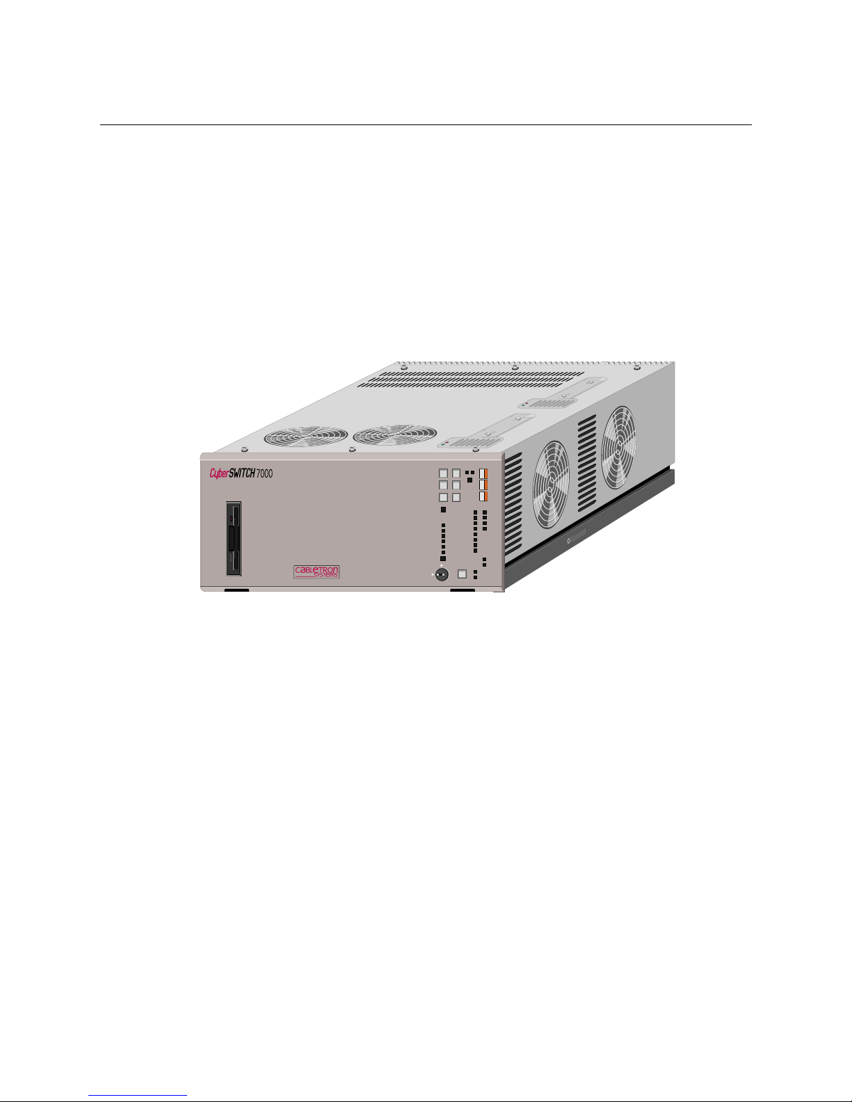
CSX7000
The CSX7000 is Ca blet ron’s High Availability, Remote Access Switc h. Because it is a mult i-system
platform with many unique features, we are devoting this entire supplement to its description.
This supplemen tal guide includes the following chapters:
• What is the CSX7000?
This chapter provides an overview of the CSX7000 in cl uding a brief description of i ts features.
• Platform Description
This chapter details CSX7000 hardware, including a description of the front panel, back panel,
and internal platform components.
• CSX7000 Cablin g
This chapter describes the cabling connections necessary for a single CSX7000, as well as a
cluster setup for multiple CSX7000s.
• Monitoring Systems
An optional management module, the EMS, provides environmental management for one or
more CSX7000s in a cluster. This chapter describes how to set up the module, and use it
appropriately to administer your system.
• CSX7000 Appendices
In the event you decide to use an SNMP agent for your EMS module, or install upgrade
modules to your existing CSX7000, these appendices provide the necess ary information . They
describe:
• SNMP Agent Support
• EMS Installation
• Processor Modul e In stal latio n
• Power Supply Replacement
Page 8
T
HE
CSX7000
OVERVIEW
The CSX7000, the high availability, remote access switch, is a multi-system platform intended for
large, central sites and Internet Service Providers. It is both modular and flexible, with capabilities
and performance to match the requirements of high-end network connectivity customers. The
CSX7000 supports a hi gh density of LAN segments, ISDN BRI or PRI, and digi tal modems , as well
as RS232, V.35, Frame Relay and X.25 interfaces. It also offers an effective means of system
manageme nt through it s optional Env ironmenta l Management System (EMS) module.
Modularity: An important feature of the CSX7000 is its ability to support multiple system groups.
Each group is a stand-alone CSX “system” based on a Pentium processor module. Use the sixteen
ISA slots of the CSX7000 as a single system group, or partition it into as many as four system
groups. A combi nation of module s ( including a processor module ) makes up a system group.
Flexibility: The CSX7000 supports a flexible setup for system groups; mix and match individual
LAN and WAN interface modules within a group to support specific needs.
High Availab i li t y : Local Area Network (LAN) and Wide Area Network (WAN) int erface modul es
have their own dedicated on-board processors and memo ry, thus lesse ning the load on the ma in
processor. TDM and MVIP bus connections al low the transfer of data betwee n cards to improve
throu g hp u t wi t h o u t u s i ng th e IS A b u s.
The fault-tolerant platform provides redundant, hot-swappable power suppli es and cooling fans.
The pla tf o rm supports bu s se g m e n t a ti o n a nd load sha ring. Fo r ba c k u p or pa ra l le l opera t i ons,
configu re re dundant system g rou p s.
Environmental Management: The platform cont ains inte lligent envir on men tal sens ors to monitor
power, temperature and other environmental functions.
GROUP PWR
ON OFF
BC GROUP
MULTIPORT BOARD
MP SERIAL PORT
BC RESET
PWR SUPPLY 1
PWR SUPPLY 2
FANS
DATA HIGHWAY
SUBSYSTEM FAULT
ENVIROMENTAL ALLERT
AUDIBLE CLEAR
TRANSMIT
RECIEVE
CARRIER
DTR
DSR
RING
RTS
CTS
LAN ATTATCHED
DISK ACTIVITY
ENABLED
DISABLED
VIDEO SELECT
UNLOCK
LOCK
MP BC
SUBSYSTEM DATA
CONSOLE
Page 9

CSX7000 9
THE CSX7000
The CSX7000 Chassis
THE CSX7000 CHASSIS
The CSX7000 is a self-contained 16 slot rack-mount unit with a passive segmentable backplane. It
can support multiple system grou ps using multip le proces s or module s. It is capable of runn ing
completely independent applic ations within the same chassis. An internal , multiplexed bus system
allows all pr ocessor modules within the chas sis to share a single f lexible disk, monitor, and
keyboard.
The CSX7000 is built with heavy industrial mater ial and includes a cooling sy stem which can
accommodat e the full chass is. The two redu ndant integral pow er supplies prov ide high availa bility
processing. You ca n hot swap each supply without affecting the CSX7000’s functions. You can
power on or off individual groups, which allows you to maintain a selected group while other
groups in the chassis rema in operational.
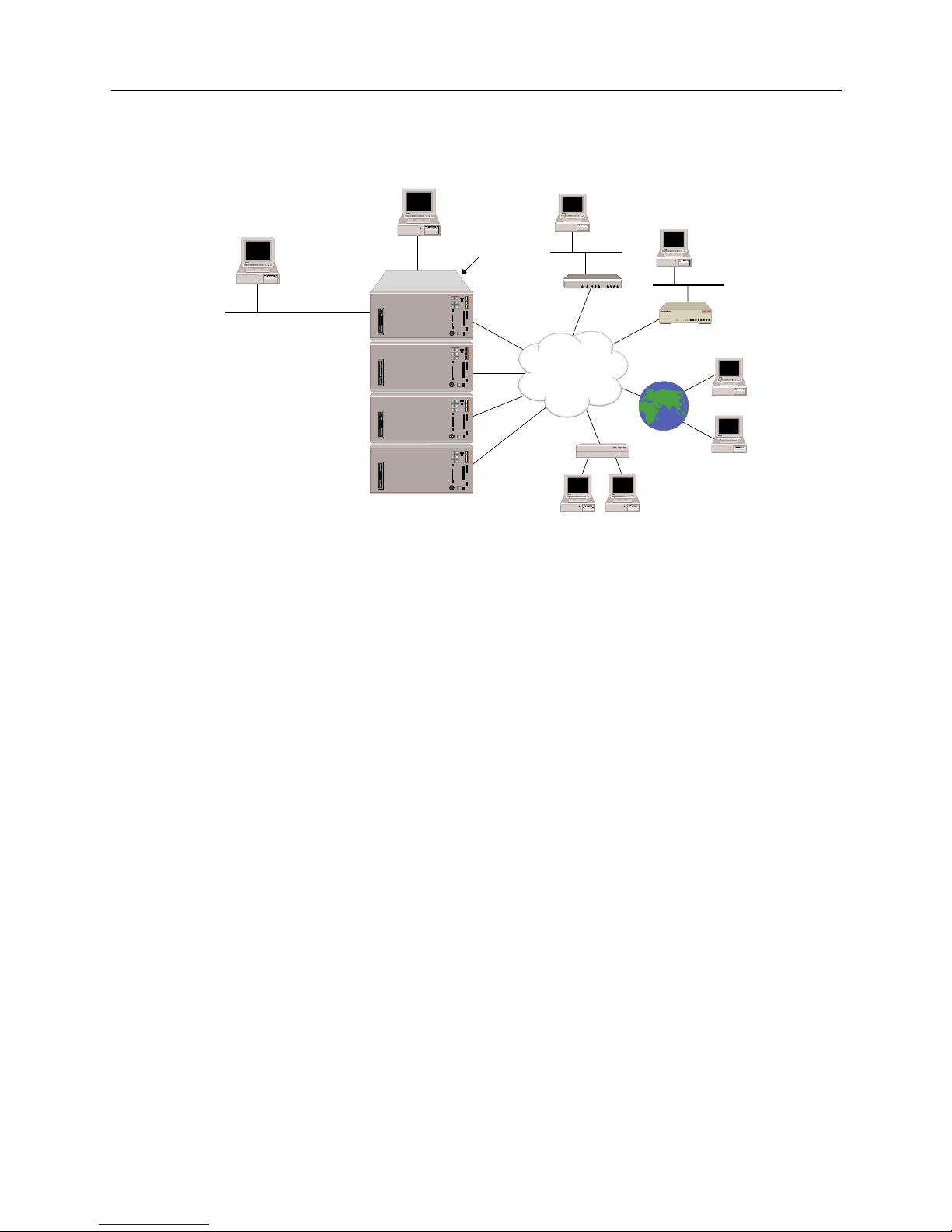
The CSX7000 contain s a sl ide rail assembly to allow for its mounting in a 19 inch RETMA rack or
cabinet. (Refer to chassis dimensions and rack/cabinet recommendations.) You can create a cluster of
CSX7000s by stacking multiple chassis and connecting them with a chassis-to chassis daisy chain
bus. (See following illustration.)
PROCESSOR MODULE
Cabletron offers two different processor modules for the CSX7000: the CSXPRO-8 and the
CSXPRO-32. These Pentium single-board CPUs are self-contained computers that include
processor, memory, and I/O. Th e amount of RAM and the speed of the processor differentiate the
available CPUs:
• CSXPRO7-8 sufficient for most remote access applications
• CSXPRO7-32 for densely-populated PRI configuration s
ENVIRONMENTAL MODULE
For each cluster of connected CSX7000s, an optional Environmental Management System (EMS)
module manages the intel ligent environmental sensors located throughout the cluster. Th e se
sensors monitor system status, including CPU operation, voltages, fuses, temperature and fans.
The EMS module c an monit or and con trol up to 31 CSX7000s connect ed as a s ingle cl uster. The EMS
module can al so b e configured as an SNMP agent for management of the environmental sensors
throu gh a rem o te S NMP man a ge r.
INTERFACE MODULES
The CSX7000 supports multiple interface modules. These interface modules combine with a
processor module to form a system group. The in t e rfa ce mo dules can include:
• Ethernet Local Area Network (LAN) Interface (singl e p ort or two port)
• ISDN Basic Rate Interface (BRI)
• ISDN Primary Rate Interface (PRI)
• digital modem (DM-8, DM-24, DM-24+, DM-30+)
• dedicated line connectivity through RS232 and V.35
• Frame Relay and X.25 support
For detailed information on these and other features of the CSX7000, refer to the User’s Guide.
Page 10
CSX7000 Guide
10 CyberSWITCH
Four Clustered CSX7000s
LAN (SNMP)
Local Console
Remote Console
(Network Administrator)
ISDN
1
2
3
4
EMS Module
B25B27
B26B28
WORKGROUP REMOTE ACCESS SWITCH
B29
E1 ONLYB-CHANNELS
LAN
10BASE-TRXTXSERVICE
B31
B30L1
B21B23
B22B24
B17B19
B18B20
B13B15
B14B16
E1DT1
D
B9B11
B10B12
B5B7
B6B8
B1B3
B2B4
POWER
Page 11

P
LATFORM DESCRIPTION
The CSX7000 consists of a platform, one or more processor modules, an optional Environmental
Manag ement System (EM S) module, and LAN/WAN int erfac e modules.
This chapter takes a closer l ook at the platform. It describes the front panel, back panel, int e rnal
platform components, and processor modules. The internal components of the platform include the
power supply, cooling system, and backplane bay.
CSX7000 P LATFORM CHARACTERISTICS
Environmental Charact e ristics
Operating Temperature : 0° to 45° C (32° to 113° F)
Storage Temperature: -20°+70°C
Operating Humidity: 20-85% non-condensing
Operating Altitude: Up to 3048 m max. (10,000 ft max.)
Non-operating Shock: 40 G, 11 ms
Physical Char acteristic s
Height: 218 mm (8.60 in)
Width: 483 mm (19.0 in)
Leng th : 641 mm (25.25 in)
Weight: 36 kg max. (80 lb. max.)
Power Supply Specifications (two power supplie s per CSX7000)
350 Watt power supply; two versions with different input AC voltages:
• Version 1
AC Input Voltage: 90 to 135 V
AC Input Current: 7.5 A
AC Input Frequency: 47 - 63 Hz
• Version 2
AC Input Voltage: 180 to 264 V
AC Input Current: 4.0 A
AC Input Frequency: 47 to 63 Hz
Regulatory Compliance
Safety: UL478, CSA C22.2 No.154, IEC 435, VDE 0806
EMI/RFI: FCC47 CFR Part 15 Subpart B Class A
System Susceptibility Specifications
Static Discharge: IEC 801-2, Severity Leve l 3
Electromagnetic Susceptibility: IEC 801-3, Severity Level 2
Frequency Band: 27 MHZ to 500 MHZ
Electrom agnetic Couplin g
Susceptibility: IEC 801-4, Severity Level 2
Disk Drives
Number of 1/3 height, IDE disk drives supported: 8
Page 12

CSX7000 Guide
12 CyberSWITCH
CSX7000 P ROCESS O R MODULE CHARACTERISTICS
Physical Char acteristic s
Height, width and length: Standa rd, full-length ISA bus card for proce ssor
Weight: 2.0 kg max. (4.4 lb. max.)
Power Requirements
90 MHZ Pentium +5V at 4.2 amp, +12V at 0.05 amp,
Processor Board: and -12V at 0.6 amp
Hard Drive (500MB):
RUN: +5V at 0.4 amp, and +12V at 0.75 amp
STARTUP: +5V at 0.4 amp, and +12V at 3.0 amp
Hard Drive (1.2GB):
RUN: +5V at 0.4 amp, and +12V at 0.75 amp
STARTUP: +5V at 0.4 amp, and +12V at 3.0 amp
Regulatory Compliance
Safety: UL478, CSA C22.2 No.154, IEC 435, VDE 0806
EMI/RFI: FCC47 CFR Part 15 Subpart B Class A
System Susceptibility Specifications
Static Discharge: IEC 1000-4-2, Severity Level 2
Electromagnetic Susceptibility: IEC 1000-4-3, Severity Level 2
Frequency Band: 27 MHZ to 500 MHZ
Page 13
CSX7000 13
P
LATFORM DESCRIPTION
CSX7000 Front Panel
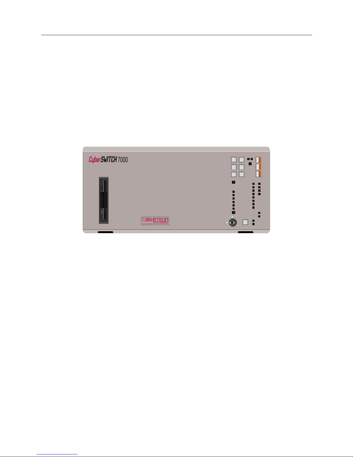
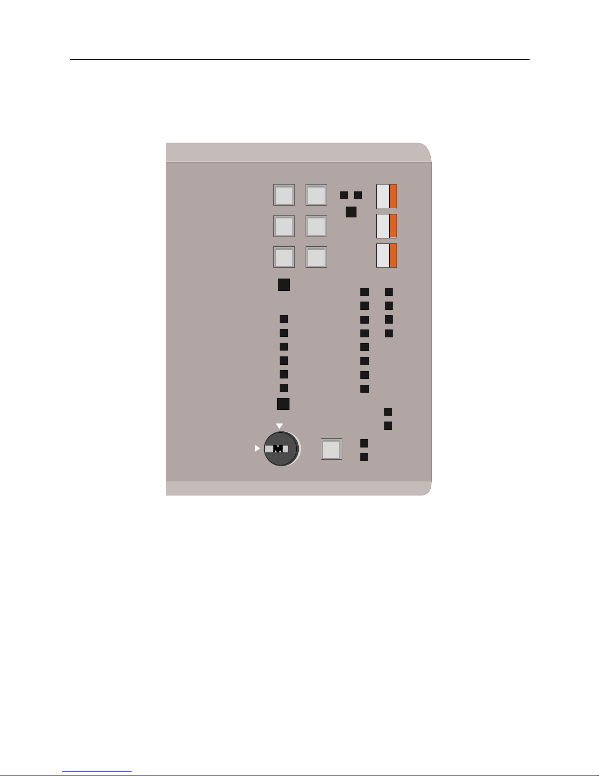
CSX7000 FRONT PANEL
The front panel of the CSX7000 consists of the following:
• push buttons which co ntrol a BC Group and Video Select
• LED indicators which identify operation of po wer supply, fans, environmental se nsors and data
highway (EMS bus)
• recessed Group Power, Group Reset, and Aud ible Clear switches
• a master console key lo ck
• a 3.5" flexible disk drive
Refer to the following illustrations and the descriptions of ea ch element on the f ront panel. In
addi tion to the fr ont pan e l LE Ds, the re i s a lso a seri e s of interior LEDs.
BC GROUP PUSH BUTTONS
BC GROUP refer s t o th e s egmen ted bac kpl ane pos it ion f or a g rou p o f ca rds that make u p a syst em.
BC stands for Bus Controller, which is the name of the pro cessor module (o r single board co mputer)
which runs the specific system within the CSX7000. Group refers to the syste m g rou p of slots
isolated on the backplane; these slots are connected together and contain a processor module. Up
to four system groups are supported per CSX7000.
The BC GROUP push buttons are the t op two pus h buttons i n the group of six. (S ee top ri ght corn er
of the fr ont p anel ). U se t he BC GROUP push butto ns to s el ect a par ti cular group fo r obs erv atio n or
administr ation when vid eo is enabl ed. By p ressing the up and down BC GRO UP push but tons, you
can swit ch be twe en t he poss ib le g roups wit hin t he pl atfo rm. The ind ica tor s t o th e r ight of t h e push
buttons display the number of the currently-selected group. (Note that the systems are numbered
1 to 4 from the le f t to the right in t he ba ckplane as viewed from the front of the platform.)
When a group is selected, its channel on the multiplexor is enabled, con necting this module to the
monitor/keyboard bus and the local flexible disk drive. Sev eral of the other fro nt panel operations
apply only to the group selected.
GROUP PWR
ON OFF
BC GROUP
MULTIPORT BOARD
MP SERIAL PORT
BC RESET
PWR SUPPLY 1
PWR SUPPLY 2
FANS
DATA HIGHWAY
SUBSYSTEM FAULT
ENVIROMENTAL ALLERT
AUDIBLE CLEAR
TRANSMIT
RECIEVE
CARRIER
DTR
DSR
RING
RTS
CTS
LAN ATTATCHED
DISK ACTIVITY
ENABLED
DISABLED
VIDEO SELECT
UNLOCK
LOCK
MP BC
SUBSYSTEM DATA
CONSOLE
Page 14

CSX7000 Guide
14 CyberSWITCH
The group numbers correspond to the number of systems configured on the backplane. You may
need to reset this value ( i.e., enter Autoconfiguration Mode) due to a change in your backplane
segmentation. To do so, perform the following:
• Power down the CSX7000.
• Power up the CSX7000. Press and hold the BC Group “select up” button during the first 5 seconds of the in itial pow e r-up cycle .
The BC Group numbers will then reset per the current backplane configuration.
MULTIPORT BOARD / MP SERIAL PORT PUSH BUTTONS
These four remaining push buttons (in the group of six) are not used with the CSX7000.
GROUP POWER SWITCH
The selected group may have the power turned on or off via the recessed GROUP POWER switch
on the front panel. This power on/off function is operational only for the specific group selected
(with BC GROUP pus h buttons) and only if the console is unlocked. This switch allows you to turn
off a specific group for maintenance purposes while other groups continue to operate.
BC RESET SWITCH
Individu al groups may be reset using the BC RESE T switch. The BC RESET switch is re ce ssed to
prevent accidental r esets. This reset funct ion is operational only for the specific group selected (with
BC GROUP push buttons), and only if the console is unlocked.
WARNING:
Even though BC RESET is avail able, we do not recomm end its use with the Cy berSWIT CH
system groups. We recommend individual power on/off cycles to ensure proper system
reset/restart.
AUDIBLE CLEAR SWITCH
AUDIBLE CLEAR i s a recess ed push-butt on switc h. It is used to clea r an envir onmental al arm only
if an audible al arm is enabled by BCV i sion.
When an environmental parameter exceeds its system limits, the environmental al ert LED displays
an amber light, and an audible alarm sounds. This alarm continues to sound until the
environme ntal parameter again falls within syst em limits, or the AUDIBLE CLEAR swit ch is
pressed.
Page 15
CSX7000 15
P
LATFORM DESCRIPTION
CSX7000 Front Panel
BC AND MP LEDS
The two columns of LEDs labeled BC and MP are not currently used on Cabletron-provided
groups. You may notice these LEDs flashing during platform power-on and system diagnostics.
Close-up of Front Panel
LAN ATTACHED LED
LAN ATTACHED illuminates when the integrated Ethernet controller in a group is attached to a
LAN.
TheCSX7000 only uses an integ rated Ethernet controller LAN con nection for the EMS.
DISK ACTIVITY LED
DISK ACTIVITY illumina te s any time hard dis k access occurs on the select ed group .
GROUP PWR
ON OFF
BC GROUP
MULTIPORT BOARD
MP SERIAL PORT
BC RESET
PWR SUPPLY 1
PWR SUPPLY 2
FANS
DATA HIGHWAY
SUBSYSTEM FAULT
ENVIROMENTAL ALLERT
AUDIBLE CLEAR
TRANSMIT
RECIEVE
CARRIER
DTR
DSR
RING
RTS
CTS
LAN ATTATCHED
DISK ACTIVITY
ENABLED
DISABLED
VIDEO SELECT
UNLOCK
LOCK
CONSOLE
SUBSYSTEM DATA
MP BC
Page 16

CSX7000 Guide
16 CyberSWITCH
SUBSYSTEM DATA LEDS
The term subs yste m refers to a specific CSX7 000. You will find this term use d both on the front
panel of the CSX7000, as well as in the BCVision program d e scribed late r in this guide.
P
OWER SUPPLY 1 /POWER SUPPLY 2
These LED s indi ca te th e power supply status. A green LED indicates that the supply is fun ctioning
normally. An amber or red LED indicates that there is a power supply fault.
F
ANS
This LED indicates the statu s of the fans. A green LED i ndicates that the fans are function ing
normally. An amber or red LED indicates that a problem exists.
D
ATA HIGHWAY
This LED indicates the statu s of the data highway (the EMS bus). A green LED i nd icates that
everything is functioning normally. An amber or red LED indicates that a problem exis ts.
S
UBSYSTEM FAULT
A green LED indicates that the electronics of the platform (i.e., subsystem) are functionin g
properly. An amber LED indicates that a fai lure has occurred.
E
NVIRONMENTAL ALERT
This LED works in conjunction with the au di b le alarm to aler t the administrator of a proble m. A
green LED indicates that no environmental alarms exi st. An amber LED indicates that an
environme ntal paramet er exceed s system limi ts, or a proce ssor module is not respon ding to querie s
by the IES. The specific alarm condition is reported to EMS, and available for display on the monitor
throu gh the BCVi s ion prog ra m.
CONSOLE KEY LOCK
The CONSOLE key lock is available to prevent unauthorized users from resetting or powering
down a group. When the key lock is in the LOCKed position, there are three functions disabled:
• BC GROUP up/down p ush buttons
• GROUP POWER push but ton
• BC RESET push-button
When the CONSOLE is LOCKed, and the VIDEO SELECT push button is used to di sable a group,
all console functions are disabled. The panel displays “LOC” in the three positions normally used to
display th e BC Group, Multi port Gr oup and MP Serial Port number s. In thi s state , none of the push
buttons are operational.
Page 17
CSX7000 17
P
LATFORM DESCRIPTION
CSX7000 Back Panel
VIDEO SELECT PUSH BUTTON
The VIDEO SELECT pus h button contr ols ac ces s to the adm inist ra tion moni tor ( the lo cal co nsol e).
It is a toggle switch; if the monitor is disabled, pressing the button will enable the monitor. If the
monitor is enabled, pres sing the but ton will disable the monit or. The c urrent state of the monit or is
displayed with the LEDS dire ctly to the ri g ht of the push button.
If the platform is in a cluster, pressing the VIDEO SELECT push button of a particular platform
supersedes any previously-selected platform. The previously-selected platform is disabled upon
making the new selection.
DISK DRIVE BAY
The flexible disk drive located on the left side of the front panel is available to all groups within the
platfor m (subsystem). When a gr ou p is selected, its channel on the multiplexor is enabled,
connecting the selected system group to this local fle xible disk drive.
The disk drive bay is located in the front of the platform behind the front panel. It provides a
location not only for the flexible disk drive, but also for the hard disk drives used by the groups in
the CSX7000. Eight t hird- height 3 .5 inc h disk driv es (IDE hard drives ) can be a ccommodated. E ach
group has one fi xed disk drive.
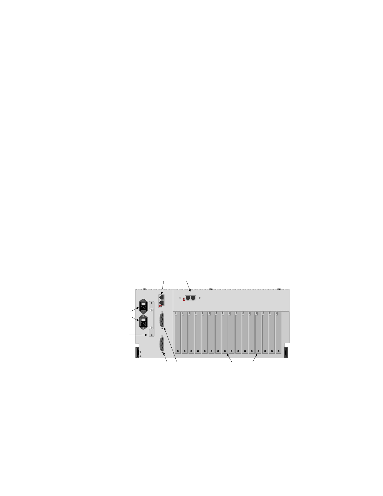
CSX7000 BACK PANEL
The CSX7000 back panel consists of a backplane bay, connectors for video as well as system
moni to ring, and AC power in p u t a nd on/of f sw itches fo r th e tw o a va i lable power su p pl ie s.
CAUTION: 1 MINUTE
POWER OFF REQUIRED
I
N
O
U
T
I
E
S
V
I
D
E
O
O
U
T
V
I
D
E
O
I
N
ERS / FT
IES SUPERVISOR
IN OUT
9 8 7 6 5 4 3 2 1
16 15 14 13 12 11 10
PS2
PS1
System Monitoring
Connectors
Power
Video
Connectors
Backplane
Slots
Install power cord
strain relief here
Page 18

CSX7000 Guide
18 CyberSWITCH
BACKPLANE
The backplane will accommodate a total of four system groups through its 16 adapter slots. The
backplane slots are numbered 1 through 16, right to left, as viewed from the rear panel. The slots
are electri cally connected in pairs of two: slots 1 and 2, slots 3 and 4, and so on. Therefore, the
backplane is configurable in multiple groups of two slots each, resulting in configurations of 2, 4, 6 or
8 slots per gro up. The processor module should alway s be located in the first slot of th e gr oup.
In most installations, slot one will provide connections for the processor module for the first group,
and slot fifteen will provide connections for the EMS processor module. Note that slot 15 is always
used for the EMS when the EMS is present.
SYSTEM MONITORING CONNECTORS
The Environmental Manage ment System (EMS) manages all the intelligen t se nsors locate d
throughout the cluste r of CS X7000s. In order to function, the EMS must properly connect to each
CSX7000 within the cluster.
The EMS connections consist of RJ-11 jacks located on the upper-left side of the back panel. The
EMS module itself is identified as IES Supervisor, and has an IN and OU T connection. To the left
of the IES Sup er viso r is t he conn ect ion to t he IES ci r cuitr y f or th e ind ivid ual pla tfor m (subs y stem ).
These IN and OUT co nnec tio ns ar e in a vertical p osit io n, and are labelled IES. For more
information, refer to EMS and Monitoring Systems.
If multiple CSX7000s make up a cluster, IES connections are daisy-chained together. Refer to
CSX7000 Cabling for further deta ils.
VIDEO CONNECTORS
The monitor connections (i.e., VIDEO) are located to the l e f t of the back panel, an d are labelled
VIDEO IN and VIDEO OUT. The VI DEO OUT c onnectio n of th e first CSX70 00 connect s to the vi deo
monitor, while th e VIDEO IN connecti on connects to th e VIDEO OUT of the second CSX7000 in the
cluster. This type of daisy-chain connection continues throughout the cluster. Refer to CSX7000
Cabling for further details.
POWER SUPPLY
To the far left of the back panel is a vertical column for the power supply bay. The bay houses dual
350 watt power supplie s (PS1 an d PS2) , which provide fault tolerance in the event of a single power
supply failu re. Each power ou tlet on the C SX7000 can be conn ected to a separate power source for
additional protection. Once the outlet s are properly connect ed to an AC power source, the power
supplies may be controlled by the switches above the outlets.
Page 19
CSX7000 19
P
LATFORM DESCRIPTION
Internal Platform Components
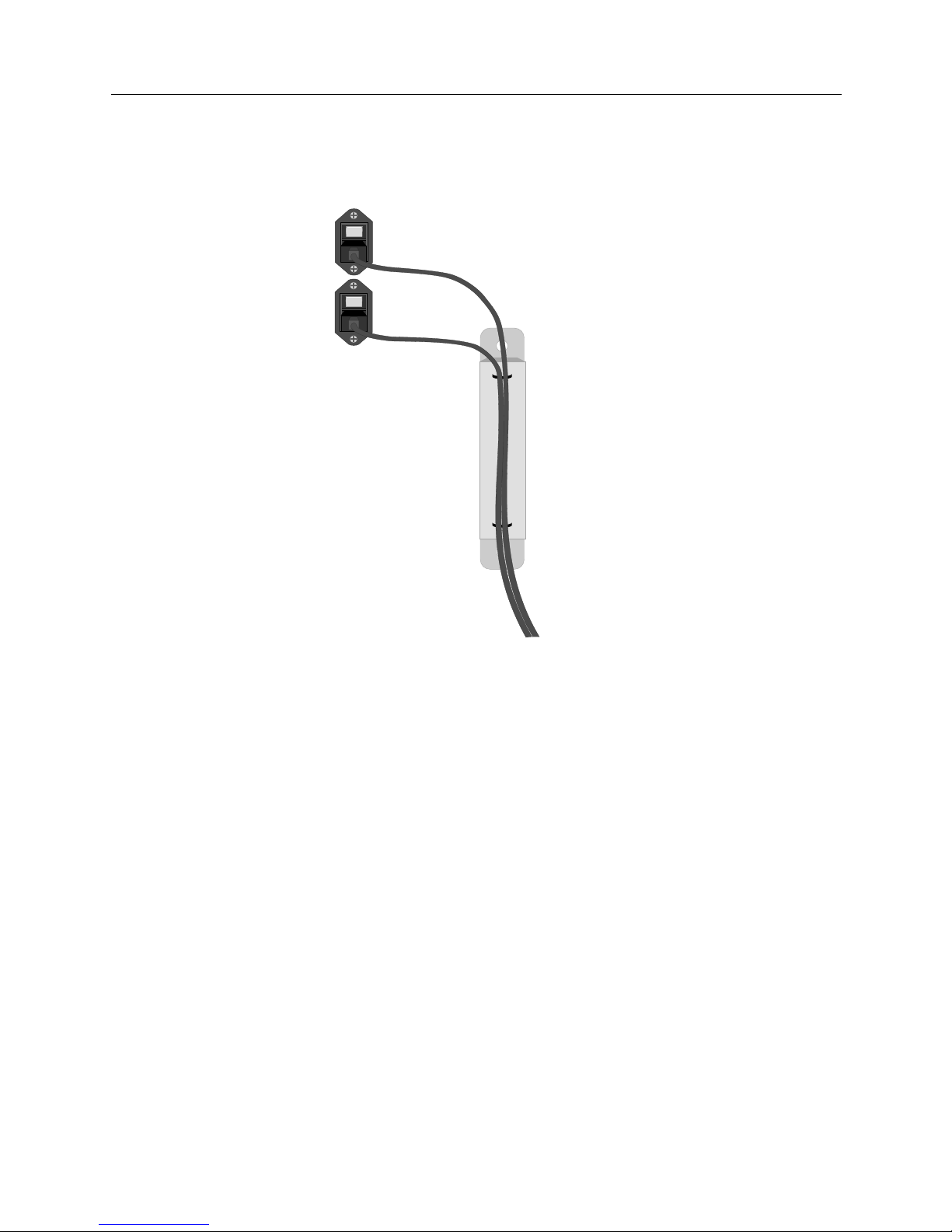
To help prevent accidental disconnec tion, we provide a strain relief bar with th e powe r co rd s. Refe r
to CSX7000 Cabling for instructions on this bar’s attachment to the back panel.
Strain Relief Bar for Power Cords
INTERNAL PLATFORM COMPONENTS
The CSX7000 consists of the following internal components:
• power supply and cooling system
• backplan e bay to su p p ort modules, including a strain re lief cross bar
• the EMS and/or IES circuitry
• one or more system groups (each including a processor module)
• platform Multiplexo r
•interior LEDs
POWER SUPPLY AND COOLING SYSTEM
The CSX7000 is built with heavy ind u strial material includi ng a cooling system which can
accommodate a full chassis. The cooling system includes tw o f ans specifically for the boar ds an d
drives, and two fans for the power supplies.
The CSX7000 has two redundant power supplies providing fault tolerant processing. Both power
supplies should always be operational. The power supplies are set up to share the power load of
the platform (subsystem), yet each power supply is big enough to manage the enti re power load, if
necessar y. Ea ch sup ply can be power ed off and re place d wit hout af fecti ng the C SX7000’s funct ions.
PS1
PS1
Page 20
CSX7000 Guide
20 CyberSWITCH
The power supply is contained in a canister type of enclosure to make the replacement as easy as
possible. (See Power Supply Installation for details.)
Note that there ar e two LEDs o n each power supply: one red and one green. When power i s on, the
green LED is lit to indicate a no-fault cond ition. If power is on and the red LE D is lit, a proble m
exists. If power is off, the LEDs will not light.
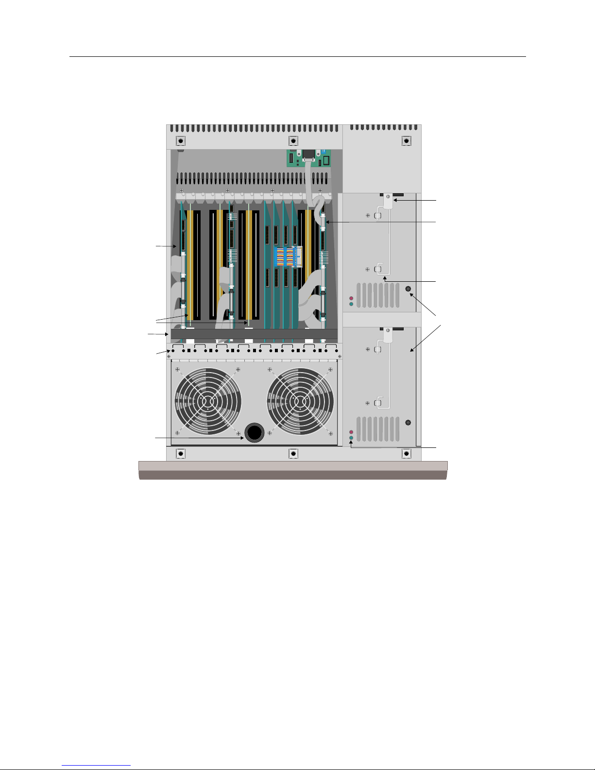
BACKPLANE BAY
The segmentable CSX7000 ISA backplan e technology is based on the conc ept of joining or shunti ng
groups of slots together. The backplane consists of eight g roups of paired slots that are isolated: a
total of 16 slots. These paired slots can be electrically joined together with special shunt boards
inserted between the standa rd ISA slots.
An ISA strain relief cross-bar runs across the top of the cards in the backplane. This bar is intended
to stabilize the backplane to avoid intermittent connections. This is especially valuable in cabinet
or rack setups in which the unit may be pushed in and pulled out repeatedly.
SAFETY LATCH- SECURE AND TIGHTEN
SCREW FOR POWER SUPPLY OPERATION.
1 MIN. POWER OFF TIME REQUIRED FOR
OPERATION- SEE MANUAL.
SAFETY LATCH- SECURE AND TIGHTEN
SCREW FOR POWER SUPPLY OPERATION.
1 MIN. POWER OFF TIME REQUIRED FOR
OPERATION- SEE MANUAL.
1 2
3 4
5 6 7 8
9 10
11 12
13 14 15 16
GREEN LIGHT = SLOT POWER ON FLASHING GREEN LIGHT = GROUP SELECTED AMBER LIGHT = SLOTS CONNECTED
Backplane
Bay
EMS Processor
Card
Dual Power
Supply
Shunts
Interior LEDs
Stopper
(Used to
Lift Fans)
Handle
Safety Latch
Power Supply
LEDs
Strain-Relief
Cross Bar
Page 21
CSX7000 21
P
LATFORM DESCRIPTION
Internal Platform Components
SEGMENTATION OF BACKPLANE
The various modules in the platform (subsystem) are preinstalle d. However, it is important to
know how the backplane is segmented for maintenance purposes. From the inside of the platf orm,
the backplane slots are numbered 1 through 16, left t o right. The slots are electrically connected in
pairs of two : slots 1 and 2, slots 3 and 4, and so on.
A system grou p ma y req uire more than 2 ca rd slot s. I n th is c ase, a pai r of slot s co uld b e ele ctri ca lly
connected together with a shunt. A group with 5 cards, fo r example, could occup y slots 1 through
5, with shunts forming the electrical connection between slots 2 and 3, and slots 4 and 5 (resulting
in a group of 6 slots). Slot 6 would remain vacant.
If you need to install a shunt, insert it into the backplane bay between the appropriate slots.
Shunt Illustration
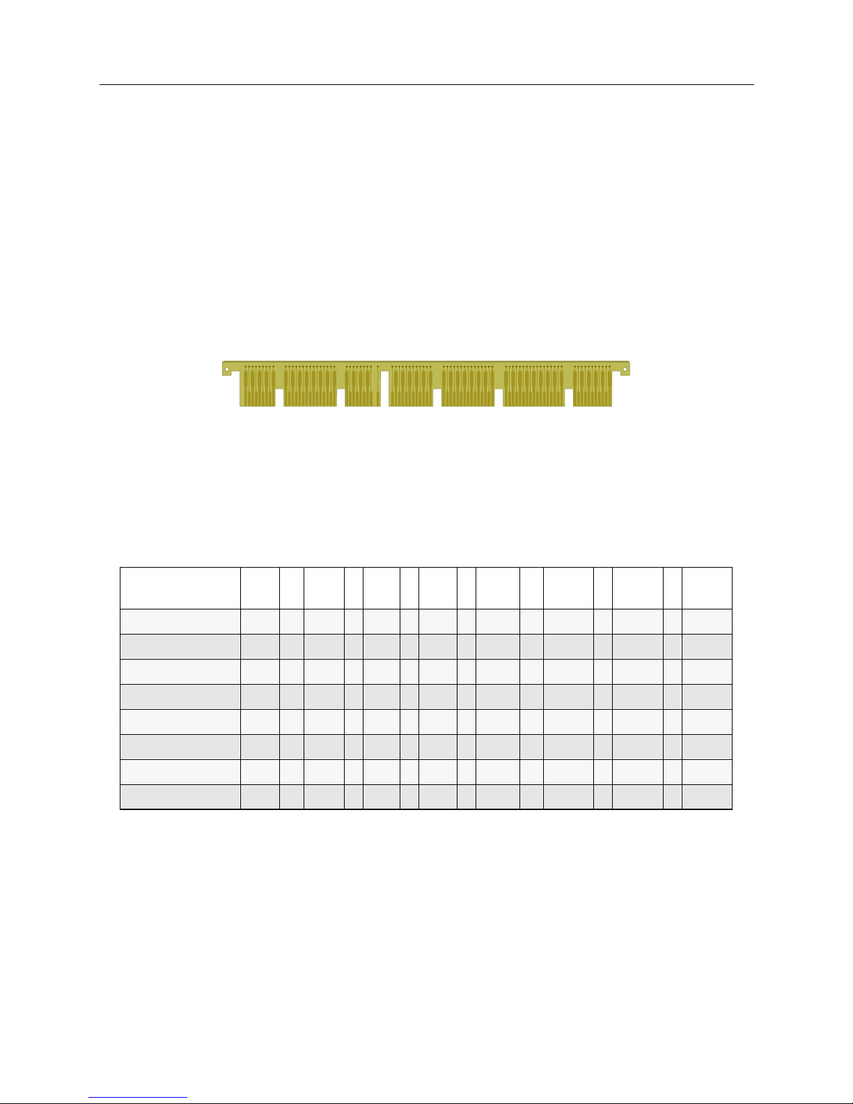
The following table lists poss ible con figuratio ns for the CSX7000. It lists t he electrical ly-pai red slot
numbers ho rizontally, and the possible group combin ations (i.e., number of car ds per group)
vertically. It identifies with an “x” where shunts are necessary for these configurations. Keep in mind
that slot 15 is reserved for the EMS processor board if EMS is to be part of the system.
Electrically Connected Slots -->
"x" indicates required shunt
Let’s consi der an example installation which supports two CSX7000s.
System Group
Segmenting
1-2 3 -4 5 - 6 7-8 9-10 11-12 13-14 15-16
4+4+4+4 x x x x
6+6+2+2 x x x x
8+4+2+2 x x x x
6+6+4 x x x x x
8+4+4 x x x x x
8+6+2 x x x x x
8+8 x x x x x x
8 +2 x x x EMS
Page 22
CSX7000 Guide
22 CyberSWITCH
The first CSX7000 is conf igured with two groups and an EMS processor:
• First group: the pro cessor board must be in sl ot 1, with the remain ing boar ds in slot s 2 throu gh
8. Shunts are required between 2 and 3, 4 and 5, 6 and 7.
• Second group: the processor board will go in slot 9, followed by the remaining two boards in
slots 10 and 11. A shunt is required between 10 and 11.
• Since this is the first of two CSX7000s, the EMS module must be located in slot 15 of this first
platform.
Our second CSX7000 is configured with four groups, as fol l ows:
• First group: the processor boa rd is loca ted in sl ot 1, wi th the r emaini ng boards i n slots 2 throu gh
6 (shunts between 2,3 and 4,5).
• Second group: the processor boar d is loca ted in sl ot 7, with th e remain ing board s in slots 8, 9 and
10 (shunt between 8,9)
• Third group: the p rocessor board is loca ted in slo t 11, with th e remaining b oards in slots 12, 13,
and 14 (shunt between 12,13)
•The last group: the processor board is located in slot 15, and the secon d board is locat e d i n slot
16.
Note that sin ce the secon d CSX7000 i s also contr olled by the EMS mod ule in the f irst CSX700 0, slo ts
15 and 16 on the second CSX7000 are available for another group.
S
YSTEM GROUP/PROCESSOR MODULE INSTALLATION
System groups (including processor modules) will be factory preinstalled. However, in the event
of an on-site upgrade, refer to EMS Installation or Processor Module Instal l ation . Note that nonconducti ve mylar shee ts should be used between PM boards and ad jacent cards; and the entire
backplane should be secure d with the str a in relief cross-bar once al l system groups are installed .
THE EMS
The Environmental Management System (EMS) is a combination of hardware and software
features that collect information and alarms, as well as carry out processor control commands in
the CSX7000 (subsys tem). The EMS Module may monitor and control up to 31 CSX7000s as a single
cluster. Howev e r, a typical cluster con f iguration cont rolled by EMS would contain a ma ximum of
eight platforms.
1st group 8 boards (maximum
allowed per system)
2nd group 3 boards
EMS module 1 boar d
1st group 6 boar d s
2nd group 4 boards
3rd group 4 boards
4th gro u p 2 boar d s
Page 23

CSX7000 23
P
LATFORM DESCRIPTION
Internal Platform Components
The EM S con s i s ts of th e f ollowin g hardw ar e c o mp o n e nts:
•an EMS processor card with its own memory and hard disk drive;
• Intelligent Electronic Sensor (IES) circuitry, which includ es an IE S card , the sensory circui ts on
the platform’s backplane which feed into this card, and an IES converter attached to the back
panel of the platform; and
• a dedicated EMS bus (data highway) for trans porting IES data from each individual platform
and group in the cluster to the EMS processor card.
Since the EMS i s an integr al part of th e primary CSX7 000, it can monitor all systems in t hat platfor m
directly. Subsequent platforms come with the necessary EMS bus, and video/keyboard I/O
cabling connections for indirect monitoring and control. (Refer to CSX7000 Cabling.) You’ll need a
local cons ole to view sta tus and perform administrat ive functio ns provided by the EM S.
Through EMS, you can power on or off individual chassis groups, allowing you to maintain one
system in the platform while others remain operational.
EMS also monitors internal parameters including temperature, voltage, fuses and CPU status.
The functions of the EMS are describ e d in de tail in Monitoring Systems.
BC PROCESSOR MODULES
A BC Processor Module consis ts of:
• a CPU or processor module card that controls a particular group,
• its associated hard disk drive, and
• appropriate cabling.
The processor module cards are designed around the concept o f h ousing a si n gl e board computer
in a small, manageable space. The processor module cards are Pentium-based processors, and
includ e stan dard PC compon ents s uch as s ystem memory, v ideo suppor t, ke yboard contr olle r, IDE
hard disk controller, diskette drive controller, serial and parallel ports. An Ethernet interface,
specifically used with the Environmental Management System (EMS), is also integrated into the
board.
The CSX7000 Processor Modules come in two different versions:
• CSXPRO7-8 (8 Megabytes RAM and a 500 Megabyte hard drive)
• CSXPRO7-32 (32 Megabytes RAM, 1.2 Gigabyte hard drive)
A single processor module supports up to seven WAN/LAN interface modules /adapter cards to
form a group. A single platform (s ubsystem) sup p orts a maximum of four groups, includin g both
system groups and EMS configurations. Once installed, the BC Processor Module is integrated with
the Platform Multiplexor for access by the local monitor, keyboard and diskette drive, as well as
access by the EMS module for monitoring and control.
Page 24

CSX7000 Guide
24 CyberSWITCH
PLATFORM MULTIPLEXOR
The multiplexor is an integral part of the CSX7000. It allows multiple groups within the CSX7000
to share a single monitor, keyboard and diskette drive. The multiplexor card operates on the
concept of channels, with one channel for each group in the platform. The multiplexor connects
each of the groups to the monitor, keyboard and diskette drive through the individual processor
module of the particular group. In order to select these multiplexed peripherals for a specific group,
use the fron t panel B C GROUP push bu ttons. When a group i s selecte d, the multiple xor enable s the
signals for the monitor, keyboard and di skette drive to pass through the selected pro cessor module.
One flexible disk dri ve is required per platf orm to service all of the processors in that platform.
INTERIOR LEDS
A strip of LEDs is located directly above the multiplexor assembly and adjacent to the dual fans on
the inside of the platform. (Refer to the illustration on page 20). These LEDs provide information
about the cards in individual slots, as well as the groups plugged into the platform’s backplane.
The numbered, circular LEDs represent the slots, and the square LEDs represent the connections
between pairs of slots.
•The circular LEDs have three states: on, off or flashing. If the LED is on (green), it indicates power
to the specific slot. If it is flashing, it indicates the slot is part of a front-panel selected group. If
it is off, there is no power to the slot.
•The square LEDs are either on or off. If on (amber), it indicates a connection between the pairs
of slots whi ch are a dja cent t o th e LED , thus form i ng a gr oup inc ludi ng the two p a irs of sl ots. I f
off, there is no connection.
1 2
3 4
5 6 7 8
9 10
11 12
13 14 15 16
GREEN LIGHT = SLOT POWER ON FLASHING GREEN LIGHT = GROUP SELECTED AMBER LIGHT = SLOTS CONNECTED
Page 25

CSX7000 C
ABLING
This chap t e r de s cribes ho w to make the cable co n nections to acco m modate the CS X 7 00 0 . It
addresses the installation of a single CSX7000 (a table top installation) as well as a cluster
installation.
For both types of installations, you will need a local console (monitor and keyboard) which
connects directly to the CSX7000. You may also have a remote console connection for network
administration, although this is not required. This remote console connection is more typical in
sites that suppo rt multiple CSX7000s, with a network administrator located in an office separate
from the equipment room.
You will also need to set the IES address for each CSX7000 in your cluster. Especially in a rack
install ati on, you shoul d se t thes e add res ses pr ior to compl et ing th e ca bl ing. For mor e info rma ti on,
refer to the EMS bu s and setting the IES address.
SETUP FOR A SINGLE CSX7000
In a syst em with a single CSX7000, cabl ing is necessary for video hookup, system monitoring, and
power supply connection. These connections are described in Platform Descr iptio n.
VIDEO CONNECTIONS
LOCAL CONSOLE CONNECTION
To set up your local console cable connection, follow these steps:
• You will be supplied with a DB-25 male-to-male cable. Connect one end of this cable to the VIDEO OUT connector on the rear of the CSX7000.
• Connect the other end of the DB-25 cab le to the video/ k e yboard breakou t b ox.
• Connect the monitor and keyboard cables fr om the local con sole to the breakout box.
CAUTION: 1 MINUTE
POWER OFF REQUIRED
I
N
O
U
T
I
E
S
V
I
D
E
O
O
U
T
V
I
D
E
O
I
N
ERS / FT
IES SUPERVISOR
IN OUT
9 8 7 6 5 4 3 2 1
16 15 14 13 12 11 10
PS2
PS1
System Monitoring
Connectors
Power
Video
Connectors
Backplane
Slots
Install power cord
strain relief here
Page 26

CSX7000 Guide
26 CyberSWITCH
REMOTE CONSOLE CONNECTI ON
To support a remote SNMP administration console, connect the CSX 7000 to the Local Area
Network (LAN) via the LAN connector on the EMS processor board. Note that this is a 10-Base T
connection.
CONNECTIONS FOR SYSTEM MONITORING
In order for the EMS to properly operate, you must set up the EMS bus (or data highway) to provide
connection from the IES of eac h subsystem to the EMS processor. With a single CSX7000, there is
no daisy-chained data highway. Yet the subsystem’s IES must still be connected to the EMS
processor. To make this connection, perform the following:
• Connect the tw o RJ-11 conne ctors l abeled IES OUT and IES SUPERVISOR IN (on the rear pan-
el), using the IES-compatible cable supplied with the CSX7000. (The cable is marked.)
• Terminate the highway by properly setting switch 1 (under the IES IN/OUT connectors) to
ON. The switch is ON when it is pointing to the left when viewed from the rear panel. Switch
2 is not used.
POWER SUPPLY CONNECTIONS
The CSX7000 has two separate powe r suppl i e s to provide fault tolerance in the event of a sin gle
power failure. For the utmost protect ion, connect eac h of the two su pplies (labeled PS1 and PS2 on
the rear panel) to a different AC power source.
To help prevent accidental disconnection, we provide a strain relie f ba r for each dual p o we r cord
pair. (This strain relief bar ships with the p ower cor ds pre a tta ched .) T o in stall , rem ove t he scre ws to
the immediate right of the AC power outlets on the back panel of the CSX7000. Align str ain relief
bar with th e exposed holes, and attach bar with screws. Then plug attach ed power cords i nto unit.
CAUTION: 1 MINUTE
POWER OFF REQUIRED
I
N
O
U
T
I
E
S
V
I
D
E
O
O
U
T
V
I
D
E
O
I
N
ERS / FT
IES SUPERVISOR
IN OUT
Power
Install power cord
strain relief here
Strain Relief Bar
for power cords
Page 27

CSX7000 27
CSX7000 C
ABLING
Setup for a Cluster of CSX7000s
SETUP FOR A CLUSTER OF CSX7000S
To set up a cluster of CSX7000s , you will need to daisy-chain together each of the system’s VIDEO
IN/OUT connectors, as well as each of the system’s IE S IN/OUT connectors (if usi ng an EMS
processor). The first CSX7000 in the cluster is called the primary subsystem, and must host the E MS
processor (if applicable).
VIDEO CONNECTIONS
LOCAL CONSOLE CONNECTION
To set up your local console cable connection on the primary subsystem, follow these steps:
• You will be supplied with DB-25 male-to-male cables. Connect one end of one of these cables
to the VIDEO OUT connector on the rear of the primary CSX7000.
• Connect the other end of the same DB-25 cable to the video/kybd breakout box.
• Connect the monitor and keyboard cables fr om the local con sole to the breakout box.
To connect remaining CSX7000s:
• For the second CSX7000, connect o ne end of an other DB-25 c able t o the VI DE O OU T co nnec tor
on the rear p anel of the subsystem.
• Connect the other end of the same cable to the VIDEO IN connector of the primary CSX7000.
• For the third CSX 7000, c onnect one end o f a th ird DB-25 cable to t he VI DE O OU T connec tor on
the rear panel of the subsys t e m.
• Connect the other end of the same cable to the VIDEO IN conn ector of th e se cond CS X7000 .
Continue this daisy-chain ing for all remaining CS X7 000s in the cluster.
R
EMOTE CONSOLE CONNECTION
To support a remote administration console, connect the primary CSX7000 to the Local Area
Network (LAN) connector on the EMS Processor Board.
CONNECTIONS FOR SYSTEM EMS MONITORING
PRELIMINARIES
In a system with multiple CSX7000s, only the primary subsystem will host the EMS processor. In
order to have the EMS processor monitor the other CSX7000s in the cluster, each CSX7000 must
have a uni que IES addr ess (for identif icati on), and each mus t be atta ched to t he dat a highway (EMS
bus). Be fore estab lishing the bus, you must be sure that the IES addresses are properly set on ea ch
CSX7000. Refer to Setting the IES Address (Monitoring Systems chapter) for de t a il s .
S
ETTING UP THE DATA HIGHWAY
Refer to the following f igure. To provide connection from the IES of ea ch subsystem to the EMS
processor, perform the following:
1. First, connect the IES of the primary CSX7000 to the EMS processor:
• On the primary CSX7000, (Sys tem 1 in th e figure, ) connect the two RJ-11 connector s labeled
IES OUT and IES SUPERVISOR IN.
• Set both switches of the IES Supervisor to the ON position (down).
Page 28

CSX7000 Guide
28 CyberSWITCH
2. Next, set up the data highway between CSX7000s :
• On the primary CSX7000 (System 1), set the termination switches f or the da ta highway to
OFF. The te r m i n a ti o n sw i t ches are under th e IES IN/OUT connectors. The switches are
OFF when pointing to the right when viewed from the rear panel.
• Make a connection between the tw o RJ - 11 connectors l ab e led IES OUT on the secon d
CSX7000 (System 2), and IES IN of the primary CSX7000 (System 1). Continue this daisychaining process until all CSX7000s are connected, setting termination switches appropriately.
On the last CSX7000 in the chain (System 4 in the figure), terminate the highway by turning ON
both of the termination switches. The switches are ON when pointing to the left as viewed from the
rear pan el .
I
N
O
U
T
I
E
S
V
I
D
E
O
O
U
T
V
I
D
E
O
I
N
ERS / FT
IES SUPERVISOR
IN OUT
PS2
PS1
I
N
O
U
T
I
E
S
V
I
D
E
O
O
U
T
V
I
D
E
O
I
N
ERS / FT
PS2
PS1
PS1 PS2
Video/Keyboard
Breakout Box
I
N
O
U
T
I
E
S
V
I
D
E
O
O
U
T
V
I
D
E
O
I
N
ERS / FT
PS2
PS1
I
N
O
U
T
I
E
S
V
I
D
E
O
O
U
T
V
I
D
E
O
I
N
ERS / FT
PS2
PS1
ON OFF
ON OFF
ON OFF
ON OFF
Termination
Disabled
Termination
Disabled
Termination
Disabled
Termination
Enabled
(last platform on EMS bus)
#1
#2
#3
#4
IES Address = 1
1: OFF (right)
2: OFF (right)
1: OFF (right)
2: OFF (right)
1: OFF (right)
2: OFF (right)
1: ON (left)
2: ON (left)
1: ON (down)
2: ON (down)
OFF
ON
Page 29

CSX7000 29
CSX7000 C
ABLING
The CSX7000 Rack or Cabinet
POWER SUPPLY CONNECTIONS
In the CS X 7 000 clus te r, each sub system has its own dua l p ower sup p l y , a nd e ac h mu s t be
connected to an AC power source. Lik e the single CSX7000, be sure to install the strain relief bar
(provided with each dual power cord pair) on each subsystem. Then plug the power cords into PS1
and PS2 respecti vely. For th e utmost prot ection, co nnect each of the two supplies (coming from PS1
and PS2) to a differen t AC po wer sourc e. Refer to prev iou s illustr ation.
THE CSX7000 RACK OR CABINET
The CSX7000s are standar d 19" RETMA units and may be mounted into any cabinet that
accommodates 19" RETMA devices. (See dimensions on following illustration). To install platforms
into the rack or cabinet, follow this procedure:
1. Be sure that the CSX7000 s are set up correctly (i.e., processor modules and interface modules
properly installed). If using the EMS module, Set the IES addresses appropriately on all
platforms. If you do not set the IES addresses now, you will need to slide the platform out after
installation to set this address.
2. Remove the middle and rear sliding rails from the sides of the platform.
3. With the middle rails still inserted into the rear rails, mount them into the cabinet using the four
brackets provided.
4. Slide the CSX7000 on the front rails into the mounted middle rails.
5. Make back panel connections.
6. When installation is complete, we s u ggest you bolt th e rack to the floo r.
CAUTION:
Do not leave the platform unattended while it is at full extension (slid out/pulled out of
the rack or cabinet). The weight of the platform may cause the rack/cabinet to tip.
Note: CSX7000 dimensions ar e larg er th an standard rack-mount PCs.
Page 30

CSX7000 Guide
30 CyberSWITCH
19.031" -0.00
483mm -0.00
Cabinet Opening
17.72" +.00/-.02
450mm +0/-.5
Top Cover Width
18.90" (480mm)
Front Panel Width
Top View
7000 Platform
EIA Standard
RS-31 O-C
18.312" +/- 0.032
465mm +/- 0.8
Center to Center
Hole Spacing
17.75" -0.00
451mm -0.00
Opening Between
RETMA Rails
Page 31

M
ONITORING SYSTEMS
You can monitor the CSX7000 cluster (each of its platforms or subsystems and each of its groups)
through the Envir onmental Manag e me nt System, or EMS. On ly one EMS module is necessary per
cluster ; it resides in slot 15 of the firs t p latform of the cluster. Th e EM S module monitors i nternal
fans and temperature, and controls the capability to power on (or off) individual platforms or
groups. It also carries out processor control commands in the CSX7000.
The EMS Processo r Module is based on the Intelligent Environmental Sensor (IES) Supervisory System.
The sens ors fo r the E MS Mod ule ar e in tegr ated into t he IES p rint ed cir cui t b oard, whic h i s adja cent
to the multiplexor board. There is an IES printed circuit board in every CSX7000. These sensors
continuously monitor the environmental conditions of the platform, including the temperature,
voltages, fan r otation and f uses. The activity of the processors in each g roup is monitored through
the EMS processor. If a fault occurs, the condition is reported to the EMS processor.
There are three different ways to interface the EMS:
• through the front panel LEDs
•with SNMP
•via BCVision
In order to interface with EMS through BCVision, you must have a valid keyboard and monitor
connection. All func tions of EMS are monitored through the video/ke yboard interf ace on the
CSX7000 primary platform. In the CSX7000 cluster, all CSX7000s must be connected through the
EMS bus (data highway). All resets and commands that are carried out on the primary platform
(through the IES and the Multiplexor) may be carried out on all other devices on the bus.
THE EMS BUS
The EMS bus is an out-of-band data highway dedicated to communication between the EMS and
the IES c irc uitry on ev ery C SX70 00 ( su bsyst em) i n a c lu ste r. I n o rde r to co mmu nicat e w it h eac h IE S
board, you must set a uni que IES address on each platform. The primary plat form (i.e., the pl atform
with the EMS processor) will always have an IES address of 1. In a cluster of platforms linked
together through the EMS bus, you can set a maximum of 31 addresses.
The EMS bus is a daisy-chained bus. Its cir cu itry includes pass- t hrough circuits that allow the bu s
to continue functioning in the event of a failure on any individual platform. However, if the daisy
chain is interrupted (disconnected) at a platform, all platforms beyond the break will be
disconnected.
Page 32

CSX7000 Guide
32 CyberSWITCH
top View of the Compartment Under the Fans
SETTING THE IES ADDRESS
The switch to set the IES addr ess is l ocated insi de the CSX7000, under th e dual fans. Lift up the fan
compartment by the round black stopper. You will find a pair of switches on the right side of the
inner co mp artment. The IE S address switch is to the far right, and is lab e led.
The IES address values are in hexadecimal. When setting the values, note the following:
• The address of the primary platform (which houses the EMS processor) must have an IES address of 1.
• Each additional CSX7000 must have a unique IES address. We suggest you number them from
2 to 31.
• You may have up to 31 platforms (and therefore, 31 IES addresses ) per cluster.
Fans
(lifted)
IES Address
Switches
Disk Drive
Bay
Disk Drive
Support
Bracket
Page 33

CSX7000 33
M
ONITORING SYSTEMS
The EMS Bus
To set the switch, perform the followi ng:
• Release the six quarter-turn fasteners on the top of the platform and remove the cover.
• Lift the front fan panel.
• Locate the I ES ad dress switches. This setting consists of eight individual switches, numbe red
one to e igh t from l eft t o r ight when vi ewed f rom t he fron t of the p lat for m. Note that switches six,
seven and eight are not used. A switch is ON when it is in the up position, and OFF when it is in
the down posi tion. To set an IES address, refer to the following table:
F
R
O
N
T
FACTORY TEST
DOWN = NORMAL
OPERATION
SPEAKER
FAN 1 FAN 2
MUX IES
OPTIONS ADDRESS
MUX OPTIONS
1: DOWN = MONITOR ONLY
2: DOWN = MON / KB / MOUSE ONLY
3: DOWN = FLOPPY ON / GROUP 1
4: DOWN = MASTER KEYSWITCH
5: DOWN = CUSTOM CHANNEL
IES
DATA BUS MUX POWER
TEMPERATURE
SENSOR
P/S
STATUS
IES
POWER
RX
TX
TX
RX
ACTIVE
ENABLED
1 2 3 4 5 6 7 8
IES Address Switch
Page 34

CSX7000 Guide
34 CyberSWITCH
IES Address Switch Settings
IES
Address
Switch 1 2 3 4 5
1 DOWN UP UP UP UP
2 UP DOWN UP UP UP
3 DOWN DOWN UP UP UP
4 UP UP DOW N UP UP
5 DOWN UP DOW N UP UP
6 UP DOWN DOWN UP UP
7 DOWN DOWN DOWN UP UP
8 UP UP UP DOWN UP
9 DOWN UP UP DOWN UP
10 UP DOWN UP DOWN UP
11 DOWN DOWN UP DOWN UP
12 UP UP DOW N DOWN UP
13 DOWN UP DOWN DOWN UP
14 UP DOWN DOWN DOWN UP
15 DOWN DOWN DOWN DOWN UP
16 UP UP UP UP DOWN
17 DOWN UP UP UP DOWN
18 UP DOWN UP UP DOWN
19 DOWN DOWN UP UP DOWN
20 UP UP DOW N UP DOW N
21 DOWN UP DOWN UP DOWN
22 UP DOWN DOWN UP DOWN
23 DOWN DOWN DOWN UP DOWN
24 UP UP UP DOWN DOWN
25 DOWN UP UP DOWN DOWN
26 UP DOWN UP DOWN DOWN
27 DOWN DOWN UP DOWN DOWN
28 UP UP DOW N DOWN DOWN
29 DOWN UP DOWN DOWN DOWN
30 UP DOWN DOWN DOWN DOWN
31 DOWN DOWN DOWN DOWN DOWN
Page 35

CSX7000 35
M
ONITORING SYSTEMS
Accessing the EMS Module
ACCESSING THE EMS MODULE
FRONT PANEL
The front panel pr ovides E MS infor mation on system activi ty th rough the acti vity i ndicato rs (LED s).
These LEDs provide information on status of power, EMS bus, processor activity, current video
and group select, and fans.
You may interact with th e EMS Modul e through the co ntrol button s f o r GROUP POWER, BC
RESET, BC GROUP select and VIDEO SELECT, as well as the Key Lock.
SNMP INTERFACE
You can configure EMS as an SNMP Agent. As an SNMP agent, EMS will send out all information
gathered on the groups in response to SNMP GET and GET_NEXT commands. EMS will then send
out alarms and acknowled gments throug h SN MP TRA Ps. As administrator, you can carry out
resets and commands through SNMP SETs.
In order to utilize this interface to EMS, you must have the Novell TCP/IP stack installed on EMS.
You must also c ustomize th e EMS module to ac commodate SNMP, as well as impor t the enter prise
MIBs (cbxbc.mib and cbxies.mib) to the network’s SNMP Manager. Refer to SNMP Agent Support
for more information.
BCVISION PROGRAM
The BCVision program is auto matically executed each time the CSX7000 is power ed on. The
program provides the user interface for information compiled by the EMS module. This includes
cluster information (on the global level), as well as more specific information on the various groups
within a particular CSX7000.
Page 36

CSX7000 Guide
36 CyberSWITCH
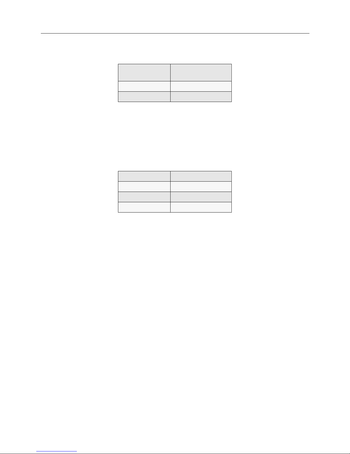
The BCVisi on pr og ram u s es ter minol ogy that ma y n eed int erpr eta tion . The fol lowi ng c ha rt sh oul d
provide clarification on the following terms:
The BCVision program runs on the BC Supervisor. To vie w and control BCVision, you must have
the BC Supervisor group (i.e., the EMS module) selected.
Because of the importance and the extent of the BCVision program, the remainder of this chapter
will describe administration through BCVision. It will address the various screens and features of
the program.
BCVision term Corre spond ing term/ explanat ion for the
CSX7000
BC (bus controller) generic term referring to a CPU. For the
CSX7000, it refers to a processor module.
BC Group system group (inclu des proce ssor modul e and
interface modules to make up a system)
BC Processor processor module for a specific syste m group
BC Supervisor processor board for the EMS module
BC Supervisory System EMS module
data highway EMS bus
ERS/FTII CSX7000
IES refers to the Intelligent Electronic Sensor
circuitry which feed s into the EM S mo dule.
Generally, “IES” refers to the circuitry for a
specific platf o rm.
subsyste m platform (generic)
Page 37

CSX7000 37
M
ONITORING SYSTEMS
Administration through BCVision
ADMINISTRATION THROUGH BCVISION
BCVision provides the user interface for the CSX7000’s EMS module. In order to view the status
screens provided by BCVision , the VIDEO SELECT switch on the front panel of your primary
CSX7000 must be enabled, and the BC Supervisor group must be select ed. Once en abl e d and
properly selected, the IES Status Screen is displayed on the monitor.
IES STATUS SCREEN
The first status screen that is displayed is t he IES Status Screen. It pr ovides general i nformation on
the various platforms (subsystems) which comprise the CSX7000 cluster. It should appear similar
to the following:
The status screen is divided into four parts:
• The first pa rt (or line, i n this case) identifies the program (BCVision) and sta tus screen (IES
Modules).
• The second part provides four menu operations: File, Supervisor, Functions , and Help.
• The third part provides general information on conditions within the platforms.
• The fourth part displays a quick reference of available ke ystroke operations - in this case, Help,
Mark and Exit .
G
ENERAL INFORMATION DISPLAY
The general information on conditions within the platforms includes: the subsystem in which the
IES is inst alled, the data highway ID of each IES, the current voltages of each subsyste m, and a
description associated with each IES.
Subsystem: This column identifies each CSX7000 in the cluster. The CSX7000 is based upon the
subsystem ERS/FT II, and will be identified as such in this column.
ID: This column ident ifies the platform or subsystem by IES address. These add resses are
determin ed by a hard ware switc h se ttin g. (Refe r to page 32 for details.) These Id numbers must be
unique.
Temperature: The temperature is displayed in degrees Celsius and reflects the temperature of the
platfo rm in whic h the I ES i s lo ca te d. (For a co nv enient con v e rsion cha rt, refer to the Help Menu.)
Voltages: The +12, -12, +5, and -5 voltages are displayed. These values reflec t the voltage levels on
the bus in the platform or subsystem containing the IES.
BCVision - IES Modules
File Supervisor Functions Help
Subsystem ID
°C +5v -5v +12v -12v Description
ERS/FT II
ERS/FT II
ERS/FT II
F1-Help | Space - Mark | F3 or Alt+F4 - Exit |
Page 38

CSX7000 Guide
38 CyberSWITCH
Description: This is a user-defined area. You may enter a text description (a maximum of 31
characters) to descri be the platform.
If a Fault Condition Exists
If a fault condition exists, the IES Status Screen will display the corresponding platform/subsystem
information in red. For detail s on the f aul t con di tion , you m ust g o to t he Functions Menu described
beginning on page 39.
Keystroke Description
The following keystrokes (or key sequences) provide access to the Main Menu options:
The following keystrok e s p rovide acce ss to the remaining interacti ve function s:
Exit BCVision
In addition to the <Al t> + <F4> key sequ ence, you may exit BC Visi on throu gh th e File Menu or via
<F3>.
Mark
Some Functions Menu options operate on the platform (actually, the IES circuitry) that is “marked”.
To mark a sensor, use the arrow keys to hi ghlight the IES to be marked, a nd press the <Space Bar >.
If an alarm condition exists, a marked IES displays on a black background. If not, it displays on a
dark blue b ack g r o u nd. To unma rk a n IES , pr e ss the < S pa ce Ba r> a g a in . The color retu rns to its
previous state.
You may perform Functions Menu operations on multiple subsystems simultaneously. To do this,
mark each IES to which the function applies, then execute the function. For example, assume that
<Alt>
This key moves the cursor to the menu bar. Use arrow
keys to th e n se l e c t a menu op tion.
<Alt> + F
Use this key se q ue nce to access th e File Menu.
<Alt> + S
Use this key se q ue nce to access th e Supervisor Menu.
<Alt> + N
Use this key se q ue nce to access th e Functions Menu.
<Alt> + H
Use this key se q ue nce to access th e Help Menu.
<Alt> + <F4>
Use this key sequence to exit BCVision. (See following).
<F1>
Use this key to view help information des cr ibing
BCVision.
<Space Bar>
To ma rk a se nsor, use the a rrow ke y s to h ig h li ght the
IES to be marked, and press the <Space Bar>. (See
following discussion).
Page 39

CSX7000 39
M
ONITORING SYSTEMS
Administration through BCVision
all sensors are marked and the maximum temperature threshold is set to 60 degrees. The new
threshold will be applied to al l of the sensors, causing BCVision to generate a tempe rature alarm
only if the temperature in one of the subsystems exceeds 60 degrees Celsius.
You also have the ability to Mark All sensors u nder the Functions Menu. This is a convenient way of
performi ng a single functi on for all of the subs ystems in the IES Supervisory System.
MENU OPERATIONS
FILE MENU
The File Men u all ows you to exit BCVi sion and return to DOS. Press <Esc> to e xit the menu.
S
UPERVISOR MENU
The options available for m th e Supervisor Menu include:
• Set Password
• Enable/Disable Conf irmation
• Enable/Disable SNMP Support
• Enable/Disable Alarm Notification
• Set Refresh Rate
• Set SNMP Status Trap Rate
Press <Esc> to exit the menu.
Set Password
This option allows you to create or m odify a password. You are prompted to enter existing and new
passwords. This added l ayer of security prevents unau thorized users from modifying the system
password.
Enter current password i f one exist s. Enter the new password. Verify the n ew password by ent ering
it a second time. Once the same password is entered twice, it becomes the new BCVision password.
A password may contain any printable ASCII character (20 - 7F hexadecimal). Passwords are not
case sensitive.
To create or modif y a BCVision passwor d, use the Set Password option from t he Supervisor Menu.
Enable/Disable Confirmation
Throughout the program, execution of any critical function is preceded by a confirmation message.
For example, if you instruct BCVision to reset a p rocessor, the p rog ram displays a mes sage
requesting you to verify the reset before the command is actually executed. This is to prevent
accidental functions fr om disrupting the system.
Page 40

CSX7000 Guide
40 CyberSWITCH
Functi ons protected wi th the confir mation message include:
• processor reset
• placing processors onl ine
• taking processors offline
• clearing res e t co u nt e rs
• CPR enable/disable
• pending offline enable/disable
• group power on/off
You may enable or disable BCVision’s confirmat ion messages. To do so, select the Enable/Disable
Confirmation option from the Supervisor Menu.
Enable/Disable SNMP Support
If you use SNMP, you may enable/disable it through this selection.
With SNMP support e nabled, BCVisio n attempts to loc ate an SNMP agent on the workstation. If
BCVision does not find an SNMP agent, an error message is displ ayed. If SNMP support is not
required, the support can be disabled and the error will be avoided.
SNMP support is enabled by default. Therefo re, the SNMP error message may occur the first time
BCVision is run, but will not occur after SNMP support is disabled.
To enable or disable SNMP support, select the Enable/Disable SNMP Support optio n fr om th e
Supervisor Menu.
Enable/Disable Alarm Notification
This capability allows you to turn on or off warning messages at the IES supervisory level. When
this capability is enabled (i.e., warning messages on), and EMS detects an alarm condition, it will:
• generate an audible alarm,
• illuminate the appropriate LED, and
• display a message on the BCVision console
Alarm notification is enabled under the follow ing condit ions:
• IES communicat ion failur e
• temperature threshold exceeded
• voltage threshold exceeded
• fan failure
• power supply failure
• nonfatal POST test failure
• bus terminator is installed backwards
• auto-configuration failure
• power down test failure
To enable or disable alar m notification, select the Enable/Disable Alarm Notification option from
the Supervisor Menu. If the option is currentl y disabled, the message Alarms Disabled will appear
in the lower right corner of the screen. If the option is currently enabled , no messa ge will app ear.
Page 41

CSX7000 41
M
ONITORING SYSTEMS
Administration through BCVision
You will be presented with a warning prompt, asking you to Acknowledge or Disable Notification. To
enable the feature, select Acknowledge. This response closes the warning scree n an d enables the
system to continue with alarm notification whenever an alarm condition occurs.
To disable the feature, select Disable Notification. Th is response closes the warning scree n,
displays th e Alarms Disabled message at the bottom of the screen, and prevents further alarm
notifications.
Set Refresh Rate
The refresh rate determines how often each IES is polled by the BC Supervisor over the data
highway, and h ow of ten the BCVision di sp lay is refreshed.
To modify the refresh rate, select Set Refresh Rate fro m the Supervisor Menu. The rate may range
from 1 to 60 seconds. The default is two seconds.
Set SNMP Status Trap Rate
SNMP is an option. If you have SNMP, you may set the status trap rate through thi s se lection.
This status trap rate is initially set to zero.
F
UNCTIONS MENU
The options available fr om the Functions Menu include:
•Set Poll Interval
• Set Reboot Timeout
• Set Temperature Threshold
•Set Date and Time
•View IES Detail
• View BC Processors
•Setup
• Scan Data Highway
•Mark All
The first t hree me nu item s (Set P oll Int erv al , Set Reboot Tim eout, and Set Temp e ratu re Thre shold)
will apply to each marked IES. (See page 38). If no IES is marked, the function will apply to the
currently highlighted IES.
Press <Esc> to exit the menu.
Set Po l l Interv a l
To monitor status, the IES is const an tly polling e ach pro cess or mo dule in the su bsyst em. The
default poll interv al is one second.
If an application is running on a processor module which keeps interrupt s dis abled fo r more t han
one second, the IES detects a processor fa ilure. EMS will au tomatically reset the pr oce ssor (which
is not recom mended), or display Inactive on the status screen.
Page 42

CSX7000 Guide
42 CyberSWITCH
If insta llations need unusual amounts of time ( more than one secon d), use the Set Poll Interval
from the Functions Menu to extend the poll interval use by IES. The new poll interval is assigned
to all marked sensors. (See page 38). If no IES is marked when this menu item is invoked, the new
poll interval is set for the currently highlighted IES on l y. The interval may range from 1 to 60
seconds.
Set Reboot Timeout
If a process or module fails to respond to a reques t by the IES, the IES ass ume s that the proces sor
has been reset. The IE S waits t he amount o f time spec ified by the “reb oot t imeout” for the proce ssor
to reboot and load the appropriate software. After this time period, if the device is still not
respondi ng, the IES resets th e p rocessor. The def au lt reboot ti me ou t is 60 seconds.
The observed reboot tim e out i s dependent upon the poll interval. After re setting a processor, the
IES checks once per poll to determine if the time specified by the reboot timeout has elapsed, at
which ti me the IES res u m e s mo n itorin g the pr ocesso r module activit y . Therefore, th e reb o o t
timeout spe cified should be greater th an the poll interval.
To modify the reb oot timeo ut, se lect Set Reboot Timeout from the Functions Menu. The new reboot
timeout will be assigned to all marked sensors. (See page 38). If no IES is marked when this menu
item is invoked, the new reboot timeout is set for the currently highlighted IES only. Specify a
timeout value in the range of 1 to 3600 seconds.
Set Temperature Threshold
Each IES constantly monitors the temperature of the subsystem in which it resides. The current
temperature is displayed on the IES Status Screen. If the temperature exceeds a maximum
threshold, an alarm is generated. The default temperature threshold is 50 degrees Celsius; we
recommend a setting of 50 degrees if no air conditioning, and 40 degrees with air conditioning.
To modif y the maximum temp e rature threshold, select Set Temperature Threshold from the
Functions Menu. The new threshold is assigned to all marked sensors. (See page 38). If no IES is
marked when this menu item is invoked, the new threshold is set for the currently highlighted IES
only. Speci f y a te mp e rature threshold from 1 to 70 degrees Celsius.
Note: Temperature is monitored in degrees Celsius only. A conversion chart (from degrees
Celsius to degrees Fahrenheit) is available through the Help Menu.
Set Date and Time
The dat e an d ti me o f the cloc k i mb e dded in th e IES ma y b e se t to th e da t e an d time of the EMS
module. Mark the IES, and then select the Set Date and Time option from the Functions Menu. The
IES clock is use d to time-stamp al arms.
To deter mine the c urr ent set tin g of t h e dat e and time in a s u bsyst em, ref er t o th e IE S De tail d i splay
(from the View IES Detail function).
Page 43

CSX7000 43
M
ONITORING SYSTEMS
Administration through BCVision
View IES Detail
You may view information describing each IES (i.e., each CSX7000) on the IES Status Screen.
Highlight the IES you wish to disp lay, and then select the View IES Detail option from the
Functions Menu. You may also use the key sequence <Alt> + V, if you prefer. The following
illustrates a sample IES Detail Display screen:
This screen displays IES conditions at the time the screen is invoked. The information displayed is
static. To update the screen, exit b y select ing the OK or Cancel butto n, and reques t to vi ew the IES
again. The fields displayed include:
• Data Highway ID of the IES as determined by its switch settings
• Description field (which may be modified form this screen)
•current Date and Time of th e real-time clock
• current +12, -12, +5, and -5 Voltages for the subsystem
• subsystem’s current temperatur e (i n degrees Celsius)
• Maximum Temperature Th reshold. When th is thre shold i s excee ded, an al arm i s genera ted by
the IES Super visory Syst e m. The user may modify this thres hold via the Functions Menu.
• Reboot Timeout, which is the amount of time that the IES will wait for a processor module to
boot. I f the p rocess or does n ot go ac tive within this in terval , the IES wil l genera te an al arm. You
may modify this thresho ld via the Functi ons Menu.
• Poll Interval, which determines how often th e IE S requests i nformation from each processor
residing in the subsyste m. You may modify th is threshol d vi a the Functions Menu.
• list of all active Alarms
View BC Processors
To monitor and control the processor modules within a platform, highlight the IES (i.e., platform),
and select View BC Proc esso rs f rom th e Fun ctions Menu (or press <Enter>). Th e BC Status Screen,
which disp lays all processo r module s or groups wi thin th e platfor m, is displ ayed. Re fer to page 45,
which describes this screen in detai l.
View SCSI Drives
This option i s no t su ppor te d on the CS X 7 00 0; SCSI is n o t cu rren tly u s ed wi t h the p roduct.
View IES Detail
Data Highway Address:
Description:
F1-Help | Tab-Next Field |
Page 44

CSX7000 Guide
44 CyberSWITCH
Setup
Use this function to configure each platform. Once you’ve selected this option, you are prompted
to select a data highway Id number. B CVision then lis ts the sub sys tem typ e and pro ces sor lo cati ons.
You can then specify the following options:
• number of power supplies to be monitored
• num b er of f ans to be m on i to re d
• "other" options (Group, Floppy, Keyboard power; Speaker On)
Choose Setup from the Functions Menu. Whe n this funct i o n is se l ected, BCVisi on determ i n es the
validity of the softwar e running on the IE S. The BCVision software revisi on must match t he I ES
software installed on the IES. If there is no match, B CVi sion prompts you to transfer ne w software
to the IES.
When prompted for the data highway id number, enter the number (1 to 31) set on the hardware
switch of the IES to be configured. If this IES has been configured previously, its current setup will
display. Refer to the following screen illustrations:
Specify the number of power supplies that are to be monitored by the IES. You may select Power
1, Power 2, or both. No selection mean s no power suppli e s are to be monitored. An alarm is
generated if a power supply fails.
Specify th e nu mber of fa ns th at are to be moni tore d by the I ES. T his fie ld defaul ts t o tw o. An alar m
will be generated if a fan fails.
Other miscellane ous options include:
• Floppy Power: Each platform contains a flexible disk drive fuse. If this option is configured, an
alarm is generate d if this f u se f ai l s.
• Keyboard Power: Each platform contains a keyboard fuse (or circuit breaker). If this option is
configured, an alarm is generated if the keyboard fuse fails.
• Speaker On: Each platform is equipped with a speaker. If the speaker is enabled, it will sound
in the event of an IES alarm.
Scan Data Highway
During a data highway scan, the BCVision program attempts to communicate with each IES.
BCVision builds an internal list of all sensors found during an initial scan. If an IES responds, it is
added to the list; otherwise a communication ti me out occurs and BCVision proceeds to the next
IES. BCVision will poll each IES on this list for status and alarm conditions. To initiate a data
Setup
Subsystem Type:
Backplane Configuration:
Power Supplies: Fans: Other:
F1-Help | Tab-Next Field |
Page 45

CSX7000 45
M
ONITORING SYSTEMS
Administration through BCVision
high wa y scan, sel e c t the Scan Data Highway option from the Functions Menu. Th is cau s es
BCVision to reb uild its intern al list of IES.
If an IES is not listed, verify its connection to the data highway. Also confirm that it is assigned a
unique identification number by inspect in g its switch setting (page 32).
Note: You can specify an IES address to scan for a specific IES, if desired.
Mark All
To select a ll se nsors list e d on the IES Status Scree n, select Mark All from the Functions Menu.
You may mark individual sensors by h ighlighting the IES on the IES Status Scr een and pressing the
<Space Bar>. (Also refer to Mark All Processors.)
H
ELP MENU
The options on the Help Menu are:
•About Help
•Overview
• Menu Commands
• ° C to ° F Conversion Chart
In addition, the <F1> function key provides help on the current function.
Press <Esc> to exit this menu.
BC PROCESSOR STATUS SCREEN
This screen displays status information on all of the BC processors installed in the subsystem of the
curren t IES. You may access this screen in one of two ways:
• highlight the desired IES and press <Enter>
• select View BC Processors from the Functions Menu
A screen similar to the following will be displayed:
G
ENERAL INFORMATION DISPLAY
For each processor module in the platform subsystem, the BC Status Screen displays the IES
identification number, the group number, the status, CPR condition, Pending Offline condition,
and descripti on.
BCVision - BC Processors controlled by IES Modules
File Supervisor Functions Help
F1 - Help | Space - Mark | Esc - return to IES Module Screen |
Page 46

CSX7000 Guide
46 CyberSWITCH
The ID refers to the da ta highway identification of th e current I ES as determined by the hardware
switch setting (page 32). Since the processor modules are in the same subsystem, the ID number is
the same for all of them.
The group number identifies which group in the segmented backplane of the subsystem contains
the processor. Groups are defined for each subsystem as part of the Setup option (from the
Functions Menu of the IES Status Screen).
The current status of each processor is displayed as follows:
Active The Processor is running.
Inactive The Processor does not respond to the IES.
Reset The Processor is resetting.
Offline The IES is holding the Proces sor offline.
Startup The supervisory softwar e is initializi ng. Status of the processor is not yet known.
Not Attached No Processor is physically attached to this connector on the multiplexor.
Group Off Power to the group of slots containing the Processor is turned of f .
The CPR field should be disabled. Cabletron does not recommend enabling this field for the
CSX7000.
The POL field indicates whether the Pending Offline function is enabled on this processor.
The Description is a “name” specified by the user to describe and identify each Processor.
Note: When naming the EMS processor, include the key word super (case insensitive) in its
description field. When BCVision automatically checks this field and finds this keyword ,
it will not allow this processor to be placed offline.
BC S
TATUS SCREEN FUNCTIONS
From the BC Status Screen the following interactive functions are ava ilable :
• Return to IES Screen
•Help
•Mark
Help
Press <F1> to view help information describing BCVision.
Page 47

CSX7000 47
M
ONITORING SYSTEMS
Administration through BCVision
Mark
Some of the op tions availa ble from the Func tions Menu operate on Processors that are “marked”.
To mark a pro cessor us e the arrow keys to po sition th e highli ght bar on the pro cessor to b e marked ,
and press the <Space Bar>. Marked processors are indicated by a background color of dark blue.
To unmark a Processor, press the <Space Bar> again, and the color will return to its previous state.
BC PROCESSOR MENU OPERATIONS
The menus are accessed from the BC Status Screen the same way they are accessed from the IES
Status Screen (pa ge 37). The options availa ble form each menu are al so the same, w ith the exception
of the Functions Menu, descr ibed immediately following.
F
UNCTIONS MENU
The options available for m th e Functions Menu include:
• Reset Processors
• Clear Rese t Counters
• Set Processor Online
• Set Processor Offline
•Enable CPR
• Disable CPR
• Enable Pending Offline
• Disable Pending Offline
• Group Power Off
• Group Power On
• View Processor Detail
•Mark All
All of the functions except Mark All will apply to all marked Processors. Marke d processor s are
indicated by a dark blue background. If no processors are marked, the function will be performed
on the currently highlighted processor.
Press <ESC> to e xi t the menu.
Reset Processor
This option resets the specified processor.
CAUTION :
Although this option is available, Cabletron does not recommend its use. To reset a
proces s or , we re c ommend a power on/off cycle for reset.
Page 48

CSX7000 Guide
48 CyberSWITCH
Clear Reset Counters
Each IES maintains three counters for each processor under its control:
• CPR Resets: th e numb er of time s th e IES ha s dete cte d a failu re and auto mat ical ly reset the processor
• Manual Resets: the number of times the user has requested the processor to b e re set through
BCVision or SNMP
• Normal Rese ts: th e number of ti mes th e proces sor has been re set du e to a c ause not listed above
(for exa mp le, upon loss of carrier function)
This optio n in iti ali zes al l of t he counte rs t o ze ro f or t h e mar ked Pr oces sor s. To pe rfo rm th is op tio n,
select Clear Reset Cou nter s from the Functions Menu.
Set Processor Online
To place an offline processor on-line, select this option. Only marked processors with a status of
“Offline” will be affecte d by execution of this function. Any processor th at is displayed on the BC
Status Screen that is not indicated as “Offline” is consider ed to be on-line , even if its status is
“Inactive”.
The status of Pending Offline will be set to Disabled by the Set Processors Online option.
Set Processor Offline
Although this option is availab le, Cablet ron do es not recomm end its use.
When this option is selected, the IES places the processor into a reset state and holds it in this
condition until the processor is once again placed online using the Set Processor Online option.
WARNING:
Pr oce ssors shoul d not be placed offline while th ey are currentl y in use. To safegu ard the
EMS processor, include the key word super in the description fiel d f or the processor. (See
page 46).
Enable CPR
CPR refers to Processor Recovery. CPR enables a processor to automatically reset a failed
processor.
CAUTION :
Although this option is available, Cabletro n does not r ecommend its use. We recommend
power on/o f f cycles to ensure proper sy stem reset/restart.
WARNING:
Do not enable CPR on processors functioning as NetWare file servers. File se rvers should
be brought down in an orderly manner by the system administrator.
Disable CPR
Select thi s op tion from the Functions Menu to disable the CPR feature on the marked processors.
We recommen d y ou disable CPR on all processors.
Page 49

CSX7000 49
M
ONITORING SYSTEMS
Administration through BCVision
Enable Pending Offline
Pending Offline allows the IES to monitor a specifically marked processor until it is reset. Once a
marked processor is inactive for any reason, IES holds the processor offline, and issues an alarm
stating that the processor is offline. This feature is recommended for all processors residing in a
platfo rm used for re mote co mm u nicat ions to all ow an ord er ly shutdow n of that plat f o rm.
Mark the processors you wish to place in the pending offline state. Select the Enable Pending
Offline option from th e Functions Menu.
Note: You cannot enable Pending Offline if a processor has the key word super in its description
field.
Disable Pending Offline
Select thi s op tion from the Functions Menu to disable the Pending Offline feature on the marked
processors.
Note: If a processor is offline when you disable Pending Offline, IES will attempt to place the
processor online.
Group Power Off
The Group Powe r Off option from the Functions Menu all o ws y ou to remo te l y turn off a g ro u p
containing a marked processor.
You may also power off multiple groups at a time by marking multiple processors.
WARNING:
Do not power of f the EMS (BC Supervisor processor) while other groups remain on.
Note: If the key word super appears in the description field of the marked processor, you will first
receive a warning message before the processor is powered off.
Group Power On
The Group Powe r On option from the Functions Menu allows you to re motely turn on a group
containing a marked processor.
You may power on multiple groups at a time by m a rk ing multip le processors. This option has the
same affect as pressing the Group Power On switch on the front panel.
WARNING:
Although you have the option to power on multi p le groups at a time, Cabletron does not
recommend this action. We recommend individ u al power on/off cycles to ensure proper
system rese t/ restart.
In addition, do NOT turn gro up power on to a grou p in a pl atform being ser viced ! If powe r
is applied to a group while boards are being inst alled or mov ed, or slot s are bein g accessed
for any other reason, damage may occur to the equipme nt.
Page 50

CSX7000 Guide
50 CyberSWITCH
View BC Processor Detail
You may view detailed information describing each processor displayed on the BC Status Screen.
Access the Processor Detail Display from the Functions Menu, or use the <Alt> + V key sequence.
The Processor Detail Display is generated for all currently highlighted processors. The following
illustrates a sample screen:
This screen displays the details of the selected processor at the time the screen is invoked. This
displayed information is static. To update the screen, exit by selecting the OK or Cancel button, and
request to v iew the processor again.
The fields displayed include:
•the Data Hi ghway ID of the sub system platfo rm as de termin ed by th e IES ha rdware swi tch s et-
ting
•the Group Nu m ber identifying the group in which the processor is installed
•the Description field, which may be modified from this screen. (Refer to description on page
46).
•the Status of the processor
• the current CPR condition
•the Pending Offline condition
•the Reset Counters: CPR Resets - the number of resets perfor med automaticall y; Manual resets -
the number of reset s reques ted via SNMP or BCVis ion; Normal Resets - t he number of resets performed due to loss of ca rrier. You may c lear t he Reset C ounter s from the Functions Menu (page
47). The counters are also cleared automatically each time new IES software is transferred to
the IES.
Note: The Normal R eset s cou nter is i ncr emen te d when a pro cess or tr ansi tio ns betw een D OS
and NetWare 3.x /4. x. Duri ng th is tr ansi tion t he pr oce ssor i s not abl e to res pond t o the
IES, and ther e f ore the IES detects a processor reset.
Mark All
To mark all processors listed on the BC Status Screen, select this option from the Functions Menu.
All other options availab le from the Functions Menu apply to these “marked” processors.
To mark individual processors, highlight the processor on the BC Status Screen and press the
<Space Ba r>.
BCVision - BC Processors controlled by IES Modules
File Supervisor Functions Help
** View BC Detail **
F1 - Help | Space - Mark | Esc - return to IES Module Screen |
Page 51

A
PPENDIX
A: SNMP A
GENT SUPPORT
This appendix describes the configuration necessary for SNMP agent support on the EMS. The
configu ration consists of three parts:
1. Configuring IP routing for the EMS module (BC Sup erv isor )
2. Customizing SNMP agent parameters for EMS, and
3. Compiling the Enterprise MIBs on your SNMP Manager
The first two st eps are i ntended to be ru n from DOS on the EMS module ( BC Supe rvisor Process or).
To prepare for this, you must guarantee that the CSX7000 containing the EMS module is selected
for video, an d the EMS mod ule (BC Su perv isor group) is t h e sele ct ed gr oup wi thin the platf orm . If
you need to set this up, pe rf orm the foll o wing:
• Press VIDEO SELECT on the platform containing the EMS module. The ENABLED LED
should light.
• Use the BC GROU P push buttons to select the BC Supervisor group (i.e., the EMS module)
within the platform.
• If BCVision is running, press <F3> to exit to DOS.
CONFIGURE IP ROUTING FOR THE EMS MODULE
The EMS module (BC Superviso r) must be connec t ed to an Et hernet LAN and configured for IP to
allow the SNMP agent to communicate with an SNMP manager.
Note: The following procedure assumes you know how to use the DOS editor and the setup
utility.
1. If the BC Supervisor’s default fram e type (ETHERNET _802. 3) does not matc h t he frame type
of your LAN, run the setup utility for the BC Supervisor’s on-board Ethernet controller to set
the desired frame type. Also edit t he file \N WCL IENT\ NET .CF G, specifying th e desired frame
type in the Link Driver section.
2. Once Ethernet support is configured, you can configure IP support. To do this, make the
following changes to the file\N WC LI EN T\NET.CFG:
a. Change the trap target parameter of the Transp ort Provider U DP section to ref lect the IP
address of the SNMP trap target (i .e., the SNMP Management station).
b. In the Proto col TCPIP secti on:
• Change ip_address to the IP address y o u wish to assign to the BC Supervisor.
• Change ip_netmask to the def a u l t subnetwork m as k .
• Change ip_router parameter to the IP address of the default r outer for al l packets being
sent to remote networks.
Page 52

CSX7000 Guide
52 CyberSWITCH
CUSTOMIZING SNMP AGENT PARAMETERS FOR THE EMS
You must customize the EMS’ S NMP Agent to reflect the requirements of your installatio n. To do
this, you mu s t modif y th e p a ra meter s in th e De sktop SNMP section of th e file
\NWCLIENT \NE T.C FG .
Note: Complete information concerning the format of the NET.CFG file and the meaning of all
its opt ions is available in th e Novell m a nual NetWare Client for DOS and MS Windows User
Guide. This manual is currently available on the World Wide Web. Locate it by starting at
Novell’s home page (htt p ://www.nove ll.com) and choosing the “doc” icon.
Note: Yo u must p ut a re turn at the end of th e last l in e of th e NET.CF G fil e, or that line i s ignor ed .
COMPILING THE ENTERPRISE MIBS ON YOUR SNMP MANAGER
The SNMP Manager needs to compile the enterprise MIBs from the CSX7000:
• First, import t he enterp rise MIBs ( cbxbc .mib and cbx ies.m ib) to the network’ s SNMP Manage r.
Refer to the Release Notes for the exact loca tion of these MIBs.
• Next, compile the enterprise MIBs on the SNMP Manager using the instructions of your particular application.
Page 53

A
PPENDIX
B: EMS I
NSTALLATION
If ordered on your initial system, the EMS module will be installed at the factory. In the event you
choose to add the EMS module at a later date, the module will be available as an upgrade. This
appendix describes the installation of the upgrade module.
OVERVIEW
The EM S con s i s ts of th e f ollowin g hardw ar e c o mp o n e nts:
•an EMS processor board with its own memory and hard di sk drive;
• Intelligent Electronic Sensor (IES) circuitry, which includes an IES boar d, the sensory circuits
on the platform’s backplane which feed into this board, and an IES converter attached to the
back panel of the platform; and
• a dedi cate d EMS bus for transporting IES data from each individual platform and group in the
cluster to the EMS processor board.
Since the EMS i s an integr al part of th e primary CSX7 000, it can monitor all systems in t hat platfor m
directly. Subsequent platforms should come with the necessary EMS bus, and video/keyboard I/
O cabling connections for indirect monitoring and control.
The steps for installation of the EMS module are:
• install the EMS processor board
• install the EMS disk drive
• install the IES converter module
• install interface cables for all components
• install software
• set up EMS bus
Note the IES board and circuitry are imbedded within the platform and do not need installation.
Page 54

CSX7000 Guide
54 CyberSWITCH
EMS PROCESSOR BOARD INSTALLAT ION
Illustration of EMS Board
The EMS processor board is a 386S X or 486-base d board wi th 4MB RAM. I t comes from t he fact ory
with defau lt switch and ju mp e r settings for EMS use. These de f a u lt settings a re :
The jumper JP1 configures the processor board for the speed of the installed CPU. Do not change
this ju mp e r settin g!
To install the EMS processor board, perform the following:
1. Check switch settings on board to assu re they conform to th e values on the previous chart.
2. Turn off power to the platform.
3. Remove top cover of platf orm.
4. Disengage the screw securing the end bracket from the rear I/O panel in line with slot 15.
5. Install the board into the CSX7000 backplane in slot 15. Secur e the board wi th the scr ew loca ted
in the end bracket.
Switch Position 1Position 2Position 3Position 4Position 5Position 6Position
7
S1 off off n/a n/a n/a n/a n/a
S2 on on off on on off on
J1 Flexible Diskette
Drive Connector
J2 IDE Hard Disk
Drive Connector
J3 BC I/O
Connector
JP1
(note: DO NOT CHANGE THE SETTING.
SET FOR CPU SPEED.)
S2
S1
Page 55

CSX7000 55
A
PPENDIX
B: EMS I
NSTALLATION
Disk Drive Installation
DISK DRIVE INSTALLATION
To install the hard disk drive, perform the following:
1. First, record the disk drive parameters (on the drive itself) for later use. These include:
cylind e r s, he a d s, wprec o mp , la nding zone and sectors.
2. Lift the dual-fan compartment.
3. Remove the top disk drive support bracket.
4. Attach the disk drive to the drive mounting bracket with four mount ing screws.
5. Install the drive into the disk drive support bracket in line with the processor slot 15. Seat the
drive by placing the two lower drive mounting bracket pins into the holes in the bottom disk
supp ort brac k e t.
6. Replace the top disk drive support by aligning the upper drive mounting bracket pin into the
proper hole on the top disk drive support. Secure this support.
SAFETY LATCH- SECURE AND TIGHTEN
SCREW FOR POWER SUPPLY OPERATION.
1 MIN. POWER OFF TIME REQUIRED FOR
OPERATION- SEE MANUAL.
SAFETY LATCH- SECURE AND TIGHTEN
SCREW FOR POWER SUPPLY OPERATION.
1 MIN. POWER OFF TIME REQUIRED FOR
OPERATION- SEE MANUAL.
1 2
3 4
5 6 7 8
9 10
11 12
13 14 15 16
GREEN LIGHT = SLOT POWER ON FLASHING GREEN LIGHT = GROUP SELECTED AMBER LIGHT = SLOTS CONNECTED
Backplane
Bay
EMS Processor
Card
Dual Power
Supply
Shunts
Interior LEDs
Stopper
(Used to
Lift Fans)
Handle
Safety Latch
Power Supply
LEDs
Strain-Relief
Cross Bar
Page 56

CSX7000 Guide
56 CyberSWITCH
7. Connect the disk power cable to the Group 8 drive power connector on the e dg e of the
backplane assembly.
8. Connect the drive I/O cable to the disk and route the other end under the IES/MUX board
assemblies to the backplane slot area.
Disk Drive Bay
IES CONVERTER MODULE INSTALLATION
The EMS pro cess or i nterf a ces with the I ES ci rcu itr y vi a the COM2 por t. (Se e pr oce ssor boar d, page
54.) This requires a converter module to change the COM2 si gnal protoco l to the IES signal
protocol. T he I ES co nver ter moun ts on t he i nsi de of th e r ear panel abov e bac kpl ane sl ot 15 . Th e IE S
converter module connects to the EMS processor board with a ribbon cable. (See following
discussion.)
Fans
(lifted)
IES Address
Switches
Disk Drive
Bay
Disk Drive
Support
Bracket
Page 57

CSX7000 57
A
PPENDIX
B: EMS I
NSTALLATION
Installing Interface Cables
INSTALLING INTERFACE CABLES
The EMS processor board requires four I/O cables for interface with:
•IES converter
•IDE hard drive
• MUX for the flexible diskette drive
• MUX f or IE S ci rc u itry
In order to make the proper in te rface conne ctions, you must locate the mul tiplexor (MUX) b o ard.
Refer to the previous illustrations of the backplane bay and the disk drive bay. The multiplexor
board (MUX) is located between the disk drive bay and the backplane bay. It is installed vertically
and crosswise in the platform. The connectors of the MUX face the backplane bay. The following
identif ies the connectors on the MUX boar d:
To install the interface cables, follow these steps:
1. Connect J1 34-pin header, flexible diskette d rive, to the MUX-floppy connector for slot 15
(between J13 and J20) on the MUX board.
2. Connect J2 40-pin header, IDE hard disk drive, to the EMS hard disk I/O cable.
3. Connect J3 26-pin header, BC I/O, to the MUX-IES circuitry connector (BC I/O jumper) J13 on
the MUX board.
4. Connect J8 10-pin header, COM 2, to the IES converter module ribbon cable.
Floppy Drive
Custom Channel
BC I/O
Custom Channel
QL I/O
Custom Channel
MP I/O
Group 1
Floppy Drive
Group 8
BC I/O
Group 8
MP I/O
Group 8
Floppy Drive
Group 1
BC I/O
Group 1
Video I/O
Power IES Connection
Muxed Flopp
y
Drive
J
2
0
J
1
3
J
2
1
J
1
4
J
2
2
J
1
5
J
2
3
J
1
6
J
2
4
J
1
7
J
2
5
J
1
8
J
2
6
J
1
9
J
2
7
J11
Page 58

CSX7000 Guide
58 CyberSWITCH
SOFTWARE INSTALLATION
The EMS software installation is a multi-part process. It includes:
•CMOS setup
• hard disk drive initialization
• DOS 6.22 installation
• BCVision inst alla tion an d SNMP Ag ent sup por t
CMOS SETUP
Before performing disk drive functions, the EMS processor requires CMOS memory setup for the
proper disk drive type:
1. Power on the CSX7000. The error message no hard disk should be displayed.
2. Press and hold the <DELETE> key during boot up. This invokes the CMOS setup utility.
3. Accept all default parameters until you reach the Sta ndard Setup section. This is where you
define the hard disk parameter for EMS use.
4. In the Standard Setup area, tab down to Hard Disk C: Type field.
5. Select type 47=User, and enter the disk drive parameters: cylinders, heads, wprecomp, landing
zone, sectors.
6. Press <ESC> when complete.
7. Exit and save CMOS settings. The system will reboot and display an error of no boot sector or
missing operating system.
HARD DISK DRIVE INITIALIZATION AND DOS INSTALLATION
The disk must be initialized for use with DOS 6.22:
1. Power on the CSX7000.
2. Press the ENABLE VIDEO control b utton.
3. Select the EMS process or (usi ng the BC GROU P butto ns) for dis play on the Local Console. (The
system groups are identified by number. They are numbered in the backplane from left to
right) . An error message of no boot sector or missing operating syst em may be dis played . Note:
This process will also select the flexible diskette drive for use with the EMS processor.
4. Install the DOS 6.22 Setup diskette in the flexible diskette drive.
5. Press the BC RESET button to reboot the EMS processor with the DOS 6.22 diskette.
6. Follow the MS-DOS prompts to ru n the Setup utility. The EMS processor should reboot at the
end of the DOS 6.22 installati on.
Page 59

CSX7000 59
A
PPENDIX
B: EMS I
NSTALLATION
Software Installation
7. At the C:> prompt, type ver and press ENTER.
8. Verify the version of DOS; it should now be 6.22.
BCVISION INSTALLATION AND SNMP AGENT SUPPORT
The BCVision program provides the user interface for information compiled by the EMS module.
The BCVision software must be i nstalled on the EMS disk drive. The BCVision software inc ludes
the following applications:
• BCVISION.EXE must run on the EMS processor to provide a user interface for IES
circuitry. Also provides suppor t f or SNMP instrumen tation.
• BCVISION.DAT support file for BCVision
• BCVISION.HLP support file for BCVision
• BCMASTER.EXE must run on the EMS processor to provide EMS bus communica-
tions
• IESFRM WR. BIN support f ile t h at co n tai ns th e so ft wa re whi c h wil l b e d ownl oad ed
and run on each IES circuitry
When the CSX7000 is powered up for the first time, an install script guides you through the steps
needed to install BCVision and IPX support. However, the script does not allow you to configure
the IP-based SNMP agent support. T o include this suppo rt, perform the followi ng procedures prior
to running the install script:
1. Power on the CSX7000.
2. Select the EMS processor for connection to the Local Console, video/keyboard, and flexible
diskette dr ive:
• Press the ENABLE VIDEO control bu tton.
• Select t he EMS m odule wi th th e BC GROUP push b utt ons. Be sure the E MS g roup number
is displayed on the front panel LED.
The console should display a messa ge simila r to the foll owing : BC Series Processor Installation.
The following software has been installed on this drive... Since this install process will be run later,
press A to abort it.
3. Insert the proper installation diskette (EMS setup) into the flexible diskette drive.
4. Type: A:\SETUP. When you see the message Press any key to continue, press any key.
5. When SETUP completes, you are ready to run the BC Series Processor install procedure.
Remove the diskette from the flexible di skette drive, and reboot the BC Superviso r ( <CTRL>
<ALT> <DEL>).
Page 60

CSX7000 Guide
60 CyberSWITCH
6. The interactive prompting begins:
• The following software has been installed on this drive... Press C to continue.
• The installation program will perform the following functions on this BC Series Processor... Press
any key.
• CREATING AUTOEXEC.BAT & CONFIG.SYS FILES. Will this system be used as a Novell Net-
Ware Workstation? Press Y.
• Select the NIC that is installed... Press 1 (for BC Series board with on-board 10Base- T Ether -
net).
• Select the VGA monitor type that is connected to this BC Series Processor... Press 2 (for mono-
chrome). This will allow the setup to work with either a color or monochrome monitor.
• Optimizing AUTOEXEC.BAT & CONFIG.SYS files. Do you want to run MemMaker to optimize
the memory configuration? Press Y, then press any key to run in batch mode and start Mem-
Maker. Mem Maker prompts are answered automatically; don’t attempt to answer them
yourself . While runni ng, MemMaker restarts the system twice.
7. Final ly , B CV is i o n should c o me up . E x i t BCVisi on (<F3>) to all o w M e mMake r to finish.
8. MemMaker displays a summary of memory use. Press <Enter> to exit MemMaker.
9. To test the complete d setup, restart the system (<CTRL> <ALT> <DEL>), and verify that
BCVision comes up.
The EMS processor is now ready for running EMS functions within the CSX7000.
Note: Control software must be loaded on each Processor Module connecte d to the IES circui try
before EMS operations will monito r the status of the Processo r Module s correc tl y. The
Processor Modules will display as INACTIVE if this control software is not running. If the
EMS module has CPR enabl ed, the E MS module re sets any INACTIVE Pr ocessor M odules.
CPR should be disabled to avoid these resets.
THE EMS BUS SETUP
The final steps to the EMS Module installation involve the setup of the EMS bus. The IES circuitry
must connect to the EMS processor via the out-of-band EMS bus. Pertinent switch settings and
physical cabling of this bus are desc ribed in the CSX7000 Ca bling and Monitoring Systems chapters.
Refer to these chapters to:
• set the IES address for each CSX platform (See Setting the IES address)
• make the proper RJ-11 connections (Setup for a Cluster of CSX7000s)
• set up the daisy-chain for multiple platforms, if applicable (Connections for System EMS Moni-
toring), and
• prop e rly set th e termina ti o n switch e s
Once you’ve p hysically se t the switches and made these co nne ctions, yo u must then initia lize the
EMS bus (following).
Page 61

CSX7000 61
A
PPENDIX
B: EMS I
NSTALLATION
The EMS Bus Setup
INITIALIZING THE EMS BUS
Use BCVision to initialize the bus :
1. From the DOS prompt, run BCVision.
2. Select Supervisor, then Enable/Disable Alarm Notification. Disable all alarms.
3. Select Function, then Scan Data Highway. Use the range “1” through “31”. A list of all the
CSX7000s and their associated IES addresses will display on the screen.
4. Select Functions, th e n Setup. Enter the address of the firs t processor module (i.e., “1”). At this
point, a dialog box may prese nt a warning that the firmware i s out-of-date. If this occu rs,
proceed with the downloading of firmware.
5. Select Functions, th e n Setup. Configure the alarm parameters with the following defaults:
• Cubix ERS/TFII (This parameter cannot be changed)
• Power Supplies:
[X] Power1
[X] Power2
•Fans:
[X] Fan1
[X] Fan2
•Other:
[X] Slot Power
[X] Floppy Power
[X] Keyboard Power
[X] or [ ] Speaker On
6. Select Functions, then Set Temperature Threshold. A dialog box will display. Set the Threshold to
“50”, then select “OK”.
7. Repeat steps 4, 5 and 6 for each succeeding processor module (i.e. , each unique IES address) in
the cluster.
8. Select Superviso r, then Enable/Disable Alarm Notification. Enable all alarms.
The EMS bus should now b e initialized.
Page 62

A
PPENDIX
C: P
ROCESSOR
M
ODULE INSTALLATION
If ordere d on you r initia l syste m, the Proc essor M odules wi ll be in stalle d at the fa ctory. In the eve nt
you choose to add a Proce ssor Module at a later date, th e module will be available as an upgrade.
This appendix describes the installatio n of the upgrade module.
PROCESSOR MODULES
A Processor Module consists of:
• a CPU or proces sor module board that controls a particular group,
• its associated hard disk drive, and
• appropriate cabling.
The proces sor module boards house Pentium-b a se d processors, and include standa rd PC
components such as system memory, video support, keyboard controller, IDE hard disk controller,
diskette drive co ntro ller, serial a nd par alle l por ts.
The CSX7000 Processor Modules come in two different versions:
• CSXPRO7-8 (8 Megabytes RAM, 500 Megabyte hard drive)
• CSXPRO7-32 (32 Megabytes RAM, 1.2 Gigabyte hard drive)
A single proce ssor module supports up to six WAN and one LAN inte rface modules/adapter
boards to form a system group. A single platform supports a maximum of four groups, incl ud ing
both system groups and EMS configurations. Once installed, the Processor Module is integrated
with the Platform Multiplexor for access by the local monitor, keyboard and diskette drive, as well
as access by th e EMS mo dule for mo nitor ing an d co nt rol.
SYSTEM GROUPS
Before installing a Processor Module, you will need the overall plan for the CSX7000. The platform
will accommodate from one to eight system groups. Each group may require a different number of
backplane slots.
Page 63

CSX7000 63
A
PPENDIX
C: P
ROCESSOR MODULE INSTALLATION
Processor Modules
Backplane Illustration
The CSX7000 uses a 8 x 2 ISA backplane configuration, which means the slots are electrically
connected in pairs of two (slots 1 and 2, slots 3 and 4, and so on). In the event that a system group
requires more than two slots, a shunt must be installed between the pairs. The shunt, resembling
an electronic comb, would be installed in the slot between the adjoining pair of slots.
Shunt Illustration
Refer to Platform Description chapter, which includes a table of possible configurations.
PM INSTALLATION SUMMARY
The installation of the Processor Module involves the following:
• Processor Module (PM) board installation
• PM di s k dr i v e in st allation
• inte rf a ce ca b le i nstalla t ion
• software setup (CMOS setup, disk drive initialization, software initialization)
1 2
3 4
5 6 7 8
9 10
11 12
13 14 15 16
GREEN LIGHT = SLOT POWER ON FLASHING GREEN LIGHT = GROUP SELECTED AMBER LIGHT = SLOTS CONNECTED
Backplane
Bay
Electrically
connected
pair of slots
Potential shunt location
(Illustrated with shunt)
Strain-Relief
Cross Bar
Page 64

CSX7000 Guide
64 CyberSWITCH
PM BOARD INSTALLATION
Illustration of the Processor Module (PM) Board
To install the Processor Module board, perform the following:
1. Locate switch 1 (S1) and switch 2 (S2) on the processor board. Set switches as fo llows:
2. Turn off power to the platform.
3. Remove top cover of platf orm.
4. Based on the number of system group s to be accommodate d within the pla tform, select an open
backplane slot. Disengage the screw securing the end bracket from the rear I/O panel in line
with selected slot.
5. Insta l l the PM bo ard int o th e se l e ct e d sl o t. Secu re the boar d with th e scr e w l o ca te d in the en d
bracket.
Note: A non-con ductive mylar sheet accompa ni e s the PM board. When in stalling the board,
place the sheet betw een the PM board an d its adjacent ca rd in t he system group. This sheet
will help protect the PM board and cards from shorting out.
Switch
Label
Position 1Position 2Position 3Position 5Position
6
S1 OFF OFF N/A N/A N/A
S2 OFF ON OFF OFF ON
J1 Flexible Diskette
Drive Connector
J2 IDE Hard Disk
Drive Connector
J3 BC I/O
Connector
S1
1 Off
2 Off
O
F
F
1 2 3 4 5
Off
On
Off
Off
On
S2
Page 65

CSX7000 65
A
PPENDIX
C: P
ROCESSOR MODULE INSTALLATION
PM Disk Drive Installation
PM DISK DRIVE INSTALLATION
To install the hard disk drive for the Processor Module, perform the following:
1. First, record the disk drive parameters (on the drive itself) for later use. These include:
cylind e r s, he a d s, wprec o mp , la nding zone and sectors.
2. Lift the dual fan compartment.
3. R emove the top disk drive support bracket (See Disk Drive Bay illustration).
4. Attach the disk drive to the drive mounting bracket with four mount ing screws.
5. Install the drive into the d isk drive support i n line with the slo t of t he Processor Module board.
Seat the driv e by placing the two lower drive mounting bracket pins i nto the holes in the
bottom disk support bracket.
6. Replace the top disk drive support by aligning the upper drive mounting bracket pin into the
proper hole on the top disk drive support. Secure the support.
7. Based on the slot number of the Proce ssor Modul e board, dete rmin e to which powe r conne ctor
group it belongs:
• slots 1 or 2: Group 1
• slots 3 or 4: Group 2
• slots 5 or 6: Group 3
• slots 7 or 8: Group 4
• slots 9 or 10: Group 5
• slots 11 or 12: Group 6
• slots 13 or 14: Group 7
• slots 15 or 16: Group 8
8. Connect the disk power cable to the Group “x” (determined in previous step) drive power
connector on the edge of the backplane assembly.
9. Connect the drive I/O cable to the disk and route the other end under the IES/MUX board
assemblies to the backplane slot area.
INTERFACE CABLES
The Processor Module board requires three I/O cables for interface with:
•IDE hard drive
• MUX for the flexible diskette drive
• MUX for the IES ci rcuitry
Refer to the Multiplexor board illustration, as well as the Processor board illustration, page 64. To
install the interface cables, follow these steps:
Page 66

CSX7000 Guide
66 CyberSWITCH
1. Connect, the J1 34-pin header , flexible disket te drive, to t he MUX flexible-diskett e connector for
slot "x" of the processor board. Refer to the following chart:
2. Connect J2 40-pin header, IDE hard disk drive, to the PM hard disk I/O cable.
3. Connect J3 26-pin header, BC I/O, to the MUX BC I/O connec tor for slot “x” of the processor
board. Refer to chart, step 1.
SOFTWARE SETUP
Software setup includes a three-step process:
• Proces sor Module CMOS se tu p
• hard disk drive initialization (PM)
• software initialization (PM)
CMOS SETUP
CMOS must be configured for proper operation of the CSX7000. Default values may be accepted
for all except the following parameters:
Slot # Group
Power
Connection
#
MUX flexible-diskette
Connector
MUX BC I/O Connector
1 or 2 1 between J27 and J11 J11
3 or 4 2 between J26 and J19 J19
5 or 6 3 between J25 and J18 J18
7 or 8 4 between J24 and J17 J17
9 or 10 5 between J23 and J16 J16
11 or 12 6 between J22 and J15 J15
13 or 14 7 between J21 and J14 J14
15 or 16 8 between J20 and J13 J13
CMOS setup section BIOS parameter CSX7000 Setting
Standard Setup date and time
Master Disk
set correct date and time; provide
type and disk parameters
Advanced Setup mouse support disabled
Chipset Setup onboard PCI ethernet disabled
Peripheral Setup serial port 2
parallel port
disabled
disabled
Page 67

CSX7000 67
A
PPENDIX
C: P
ROCESSOR MODULE INSTALLATION
Software Setup
The procedure to run the CMOS Setup information is as follows:
1. Power on the CSX7000. An error message no hard disk should be disp layed for the se lected
Processor Module board.
2. Reset the processor module by pressing the BC RESET button.
3. Press and hold the <DELETE> key during boot up. This will invoke the CMOS utility.
4. In the Standard Setup sec tion:
• set the correct time and date.
•tab down to Hard Disk C: . Type field.
• Select type 47=User, and enter the disk drive parameters (cylinders, heads, wprecomp,
landing zone, sectors).
5. In the Advanced Setup section, disable mouse support.
6. In the Chipset Setup section, disable Onboard PCI ethernet.
7. In the Peri p hera l Setup section, disable serial port 2 and the parallel port.
8. No changes need to be made to the Power Management Setup section. Press <ESC> when done.
9. Exit and save CMOS settings. The system will reboot and display an error of no boot sector or
missing operating system.
HARD DISK DRIVE INITIALIZATION AND DOS INSTALLATION
The disk must be initialized for use with DOS 5.0.
1. Power on the CSX7000.
2. Select the Processor Module (using the BC GROUP buttons) f or display on th e Local Console.
(The system groups are identified by number. They are numbered in the backplane from left to
right) . An error message of no boot sector or missing operating syst em may be displayed. This
process will also select the flexible diskette drive for use with the Processor Module.
3. Install the DOS 5.0 Setup diskette in the flexible diskette drive.
4. Press the BC RESET button to reboot the PM processor with the DOS 5.0 diskette.
5. Follow the MS-DOS prompts to ru n the Setup ut ility. The PM proc e s sor should reboot at the
end of the DOS 5.0 inst allation.
6. At the C:> prompt, type ver and press ENTER.
7. Verify the version of DOS; it should now be 5.0.
Page 68

CSX7000 Guide
68 CyberSWITCH
PM SOFTWARE INITIALIZATION
For instru ctions on Central Site software installation onto t he Processor Modu le, refer to the
Upgrading Sys t em Software chapte r o f th e User’s Guide.
Note: DOS 5.0 must be used wit h Central Site syst e m sof tware.
INTERFACE ADAPTERS
Interface adapters combine with processor modules to form "system gro u ps". Each sys tem group
typically has a LAN adapter and at least one WAN adapter. The interface adapters include:
LAN adapters:
• Ethernet - one port (EN-1)
• Eth e rnet - two port (EN-2)
WAN adapters:
• Basic Rate Interface (BRI-4)
• Primary Rate Interfaces (PRI-8, PRI-23, PRI-23/30)
• Protocol Expansion board (PXC)
Other:
• Digital Modem (DM-8, DM-24, DM-24+, DM-30+)
• RS232 serial inter face (RS232)
• V.35 serial interface (V.35)
Page 69

CSX7000 69
A
PPENDIX
C: P
ROCESSOR MODULE INSTALLATION
Interface Adapters
The following is an example of a typical CSX7000 arrang ement with a full array of interface
adapters. Note that the LAN adapte r is always positi oned in the slot farthest from its processor
module board:
Sample CSX7000 Setup
For specific information on interface board installation, switch settings, jumper settings, and
cablin g , re f er to the Har dw are Overv iew and H ar dwa re In stal latio n chapters of the User’s Guide.
Slot Board
1 Processor Module (System Group 1)
2 WAN
3 WAN
4 WAN
5 WAN
6 WAN
7 WAN
8 LAN
9 Processor Module (System Group 2)
10 WAN
11 WAN
12 WAN
13 WAN
14 LAN
15 EMS Module (System Group 3)
16 empty
Page 70

A
PPENDIX
D: P
OWER SUPPLY REPLACEMENT
Both power supplies shou ld always be opera tional. The pow e r supplies are set up to share the
power load of the platform (subsystem), yet eac h power supply is big enough to manage the entire
power load, if necessary. If there is a fa ilure with one of the power supplies, you may power off the
supply in question , and replace it without af fecting the CSX7000’s functions. The power supply is
contained in a canister type of enclosure to make the replacement as easy as possible.
DIAGNOSING A FAULTY POWER SUPPLY
LEDs on each power supply reflect the status of the supply. These LEDs are located on the top of
each supply. When power is on, the green LED is lit to indicate the supply is functioning and
providing power to the pl atform. The red LED is li t to indicate a power suppl y fault. When power
is off, neither LED will light. Because the LEDs on the power supplies are only visible when the top
panel is removed from the platform, the CSX7000 provides a duplicate set of LEDs on the front
panel.
REPLACING A FAULTY POWER SUPPLY
1. Turn off the power to the faulty power supply via the appropriate PS switch on th e upper lefthand corner of the platform’s backplane:
2. Remove the cover to the CSX7000:
• Release the six quarter-turn fasteners securing the cover.
• Lift the cover off the platform.
3. Verify that the power supply is indeed off. The LEDs on the faulty power su pply shoul d NOT
be lit.
CAUTION: 1 MINUTE
POWER OFF REQUIRED
PS2
PS1
Power
Supply2
Power
Supply1
Page 71

CSX7000 71
A
PPENDIX
D: P
OWER SUPPLY REPLACEMENT
Replacing a Faulty Power Supply
4. Unscrew the safety latch securing the faulty power supply.
5. Pull up on the handle to remove the power supply.
6. Insert the new power supply. Ensure that it is firmly seated.
7. Secure the power supply with the safety latch released in step 3.
8. R eplace the top cover and secure with the quarter-turn fasteners.
Page 72

CSX7000 Guide
72 CyberSWITCH
I
NDEX
A
adapters 68
alarm notification 40
audible clear switch 14
B
back panel 17
backplane 18, 63
cross-bar 20
BC group 13
BC LEDs 15
BC processor detail 50
BC reset switch 14
BCVision
administration
37
BC status scre en 45
exit 38
installation 59
BCVision program 35
bus controller 13
C
cabling 25
for a single platform 25
for multiple platforms 27
CMOS 66
CMOS set u p 58
COM2 por t 56
compliance notices 3
configurations of system groups 21
confirmation 39
CPR 48
cross-bar 20
D
daisy-chain 27
data highway 16, 23, 31, 44, 53
cable connections 27
initializing the bus 60
date 42
disk drive bay 17, 56
disk drive initialization 58
disk drive insta lla tion 55, 65
EMS 55
disk drives 11
DOC notice 4
E
EMS 18, 22, 31
cabling 57
DOS installation 58
EMS bus 31
initializing the bus 61
processor board installation 54
software installation 58
EMS bus , See data high way.
EMS disk drive
55
EMS installation 53
EMS interface cables 57
EMS processor board 54
enterprise MIBs 52
environmental alert 16
enviro nmental ch a racteri stics 11
Environmental Management System, See EMS.
Ethernet support
51
F
fans 16, 19
FCC notice 3
file menu 39
frame type 51
fun ct i ons men u 41, 47
G
group power 49
group power switch 14
H
help m enu 45
I
IES 23, 31
IES address 31, 32
IES conve rter module 56
IES detail 43
IES supervisor 18
installation 22
BCVision 59
Intelligent Electronic Sensor (IES) circuitry, See IES.
interface adapters
68
interface cables 65
IP routing 51
K
key lock 16
Page 73

CSX7000 73
I
NDEX
L
LAN adap ter s 68
LEDs 15
M
menu operations 39
MIBs 52
monitoring systems 31
MP LEDs 15
MP serial port 14
multiplexor (MUX ) board 24, 57
multiport board 14
MUX con ne ction cha rt 66
N
net.cfg file 52
P
password 39
pending offline 49
physical characteristics 11
platfo rm ch a r ac te r i s tics 11
platform description 11
platform multip le xor 24
platform, typical setup 69
polling interval 41
power requirements 12
power supply 16, 18, 19, 29
LEDs 20
Power Supply installation 70
power supply specifications 11
processor module 22
board illustration 64
cabling 65
components 23
descripti on 62
disk drive insta lla tion 65
DOS 67
installation 62
software setup 66
product ove rview 8
push buttons 13, 14
R
refresh ra t e 41
regulatory compliance 11, 12
remote co n s ole conn e ct i o n 27
reset processor 47
S
SCSI drives 43
set processor online/offl ine 48
setup 44
shunt 21, 63
SNMP agent support 51, 59
SNMP interface 35
strain relief bar 19, 26
subsystem 16
primary 27
subsystem data LEDs 16
supervisor menu 39
switches 14
system group 22, 62
T
temperature 42
time 42
V
VCCI notice 4
video connections 27
video conn e ctors 18
video sele ct 17
W
WAN ada pters 68
 Loading...