

Cabletron Systems CyberSWITCH CSX150, CyberSWITCH CSX154, CyberSWITCH CSX155, CyberSWITCH 150 User Manual
Page 1

SMALL OFFICE
REMOTE ACCESS SWITCH
USER’S GUIDE
Release 7.2
Cabletron Systems
(603) 332-9400 phone
(603) 337-3075 fax
support@ctron.com
Page 2

USER’S GUIDE
2 CyberSWITCH
NOTICE
You may post this document on a network server for public use as long as no
modificati ons are ma de to th e docume n t .
Cabletron Systems reserves the right to make changes in specifications and other
information contained in this document without prior notice. The reader should in
all cases consult Cabletron Systems to determine whether any such changes have
been made.
The hardware, firmware, or software described in this manual is subject to change
without notice.
IN NO EVENT SHALL CABLETRON SYSTEMS BE LIABLE FOR ANY
INCIDENTAL, INDIRECT, SPECIAL, OR CONSEQUENTIAL DAMAGES
WHATSOEVER (INCLUDING BUT NOT LIMITED TO LOST PROFITS) ARISING
OUT OF OR RELATED TO THIS MANUAL OR THE INFORMATION
CONTAINED IN IT, EVEN IF CABLETRON SYSTEMS HAS BEEN ADVISED OF,
KNOWN, OR SHOULD HAVE KNOWN, THE POSSIBILITY OF SUCH
DAMAGES.
©Copyrigh t 1998 by Cabletron Sy stems, Inc. All rights reserved.
Cabletron Systems, Inc.
P.O. Box 5005
Rochester, NH 03866-500 5
Order Number: 9032450
VIRU S D ISCLAIMER
Cabletron Systems has tested its software with current virus checking
technologies. H owev er, because no anti-vir us sy stem is 100% reliable, we strongly
cauti on you to wr ite pro tect and th en verif y that th e Licen sed Sof tware, pr ior to
installing it, is virus-free with an anti-viru s system in which yo u have confi denc e.
Cabletron Systems makes no representations or warranties to the effect that the
Licensed Software is virus-free.
Copyright © July 1997, by Cabletron Systems, Inc. All rights reserved.
Only qualified personnel should perform installation
procedures.
!
CAUTION
Page 3

Small Office Remote Access Switch 3
TRADEMARKS
Cabletron Systems, CyberSWITCH, MMAC-Plus, SmartSWITCH, SPECTRUM,
and SecureFast Virtual Remote Access Manager are trademarks of Cabletron
Systems, Inc.
All other product names m entioned in this manual are tradema rks or registered
trademarks of their re sp e ctive companies.
COPYRIGHTS
All of the code for this product is copyright ed by Cable tron System s , Inc.
© Copyright 1991-1997 Cabletron Systems, Inc. All rights reserved. Printed in the
United States of America .
Portio ns of the code for this p roduct are co pyrighted by the follow ing corpor ations:
Epilogue Technolo gy Co rporat io n
Copyright 1991-1993 by Epilogue Technology Corporation. All rights reserved .
Livingston Enterprises, Inc.
Copyright 1992 Livingston Enterprises, Inc.
Security Dynamics Technologies Inc.
Copyright 1995 by Security Dynamics Technologies Inc. All rights reserved.
Stac El e c troni cs
Stac Electronics 1993, including one or more U.S. Patents No. 4701745, 5016009,
5126739 and 5146221 and other pending patents.
Telenetw orks
Copyright 1991, 92, 93 by Telene tworks. All rights reser ved .
FCC NOTICE
This device complies with Part 15 of th e FC C rules. Operation is subject to the
following two conditions: (1) this d e vice m ay no t cause har mful interference, and
(2) this device must accept any int erference received, includ ing interference that
may caus e undesire d o pe ra ti on.
NOTE: This equipment has been tested and found to comply with the limits for a
Class A digital device, pursuant to Part 15 of the FCC rules. These limits are
designed to provide reasonable protection against harmful interference when the
equipment is operated in a commercial environment. This equipment uses,
generates, and can radiate radio frequency energy and if not installed in
accordance with the operator’s manual, may cause harmful interference to radio
communications. Operation of this equipment in a residential area is likely to cause
interference in which case the user will be required to correct the interference at his
own expense.
Page 4

USER’S GUIDE
4 CyberSWITCH
WARNING : Changes or modific ations made to this d evice wh ich ar e not expr essly
approved by the party responsible for compliance could void the user’s authority
to operate the equipment.
DOC NOTICE
This digital apparatus do es not exceed the Class A limits for radio noise emissions
from digital apparatus set out in the Radio Interference Regulations of the
Canadian Departme nt of Commun ications.
Le présent appareil numérique n’émet pas de bruits radioélectriques dépassant les
limites applicables aux appareils numériques de la class A prescrites dans le
Règlement sur le brouillage radioélectrique édicté par le ministère des
Communicatio ns du Cana d a.
VCCI NOTICE
This is a Class 1 product based on the standard of the Voluntary Control Council
for Interference by Information Technology Equipment (VCCI). If th is equipment
is used in a domestic environment, radio disturbance may arise. When such
trouble occurs, th e user may be requir e d to take correc tive actions.
CABLETRON SYSTEMS, INC. PROGRAM LICENSE AGREEMENT
IMPORTANT: Before utilizing this product, carefully read this License Agreement.
This document is an agreement between you, the end user, and Cabletron Systems,
Inc. ("Cabletron") that sets forth your rights and obligations with respect to the
Cabletron software program (the "Program") contained in this package. The
Progra m may be contai ned in fi rmware, ch ips or ot her media. BY UTILIZ ING THE
ENCLOSED PRODUCT, YOU ARE AGREEING TO BECOME BOUND BY THE
TERMS OF THIS AGREEMENT, WHICH INCLUDES THE LICENSE AND THE
LIMITATION OF WA RRANTY A ND DISCLAIMER O F LIABILITY. IF YOU DO
NOT AGREE TO THE TERMS OF THIS AGREEMENT, PROMPTLY RETURN
THE UNUSED PRODUCT TO THE PLACE OF PURCHASE FOR A FULL
REFUND.
Page 5

Small Office Remote Access Switch 5
CONTENTS
Using this Guide 22
Documentation Set 23
Guide Conventions 24
SYSTEM OVERVIEW 25
The CyberSWITCH 26
The Cybe rS W I TC H Ne t w or k 26
Unique System Featur es 27
Interoperability Overv iew 29
Interoperability Protocols 29
Interoperability Devices 30
Security Overview 31
Network Interface Overview 31
System Compon e nts 32
Remote ISDN Devices 32
Switches Supported 33
Hardware Overvi ew 34
Safety Considerations 34
System Platforms 35
CyberSWIT CH Cha r acteristics 35
CyberS WITCH Series 36
CyberSWITCH Front Panel 36
CyberSWITCH Back Panel 37
Software Overview 39
Overview 39
System software 39
System Files 39
Configuration Files 39
Operational Files 40
User Level Security Files 41
SYSTEM INSTALLATION 42
Orderi n g IS DN Service (US Only ) 43
Overview 43
Orde ring NI-1 Lines Using EZ-ISDN Code s 43
Orde ring NI-1 Lines Using NI-1 ISDN Ordering Codes 43
For Non-POTS Devices 43
For Single POTS Devices 43
For Dual POTS Devices 44
Page 6

USER’S GUIDE
6 CyberSWITCH
Ordering BRI ISDN Lines using Provisioning Settings 44
Provisioning Settings for AT&T 5ESS Switches 45
AT&T 5ESS NI-1 Service 45
AT&T 5ESS Custom Point-to-Poin t Service 46
Provision Sett ings for Northern Telecom DMS-100 Switches 46
Northern Telecom DMS100 NI-1 Service 47
Northern Telecom DMS100 Custom Service 48
Hardware Installat ion 49
Pre-Installation Requirements 49
Accessing the CyberSWITCH 50
Overview 50
Making Connections 50
Direct Co nne ction 50
Null-Modem Connection to a PC 50
Chan g i n g th e B a u d Rate 52
Remote Connec tion using Telne t 52
Establishing an Administration Session 53
Powering On 53
Accessing th e Re lease Notes 54
Upgrading System Software 56
Overview 56
Upgrading Software 56
Local Software Upgrade 57
Local Upgrade of the Second Stage Boot (SSB) 57
Local Upgrade of the Operational Software (OSW) 58
Remote Software Upgrade 58
Remote Upgrade of the Second Stage Boot (SSB) 59
Remote Upgrade of the Operational Software (OSW) 60
Chan g e De fault s to Se c u re Syste m 61
Return Conf iguration to Factory Defaults 62
Accessing th e Re lease Notes 62
BASIC CONFIGURATION 63
Configuration Tools 64
Overview 64
CFGEDI T 64
Executing CFG EDIT 64
Saving CFGEDIT Changes 65
Dynamic Management 65
Executing Dynamic Management 65
Utility Dynamic Management Commands 66
Saving Dynamic Managem e n t Changes 66
Default Configuration 67
Using the Network Worksheets 67
Using the Configuration Chap ters 68
Page 7

Small Office Remote Access Switch 7
Configuring Resources and Lines 69
Overview 69
Resources 69
Configuring Resour ces 69
Resource Configuration Elements 71
Resource B ackground Information 71
Lines 72
Configuring Line s 72
Configuring Changes fo r a COM M P O RT Res ou rc e 73
Line Configuration Elements 74
Line Background Information 77
Subaddresses 78
Configuring a Subaddress 78
Subaddress Configuration Elements 78
Subaddresses Background Information 78
POTS Option 78
Configuring the POTS Option 78
POTS Configuration Ele m ent s 80
POTS Background Information 80
Configuring Basic Bridging 81
Overview 81
MAC Layer Bridging Option 81
Enabling/Disabling Bridging 81
MAC Layer Bridging Configuration Elements 81
MAC Layer Bridging Background Info rma tion 82
Configuring Basic IP Rou ting 83
Overview 83
Interne t P rotocol (IP) Option 83
Enabling IP 83
IP Option Configuration El e ments 84
IP Background Information 84
IP Operating Mode 84
Configuring the IP Operating Mode 84
IP Operating Mode Configuration Elements 85
IP Operating Mode Background Information 85
IP Network Interfaces 86
Configuring Interfaces 86
Network Interface Configuration Elements 88
IP Network Inte rface Background Inform ation 93
IP RIP and the IP Network Interf aces 97
IP RIP over Dedicated Connections 101
IP Host Operating Mode and the IP Network Interfaces 103
Using Multiple IP Addres ses 103
Static Routes 105
Configuring Static Routes 105
Static Route Configurati on Elements 107
Static Route Background Information 109
Default Routes 110
Configuring Default Routes 110
Default Route Configuration Elements 110
Page 8

USER’S GUIDE
8 CyberSWITCH
Routing Information Protocol (RIP) Option 111
Enabling/Disabling IP RIP 111
IP RIP Configuration Elements 112
IP RIP Background Information 112
SECURITY 113
Security Overview 114
Overview 114
Security Level 114
Syste m Opti ons an d I n f or mation 115
Device Level Databases 115
User Level Databases 116
Off-node Server Information 116
Network Login Information 116
Configuring Security Level 117
Overview 117
No Security 119
Configuring No Secur ity 119
Device Level Security 120
Configuring Device Level Security 120
Device Level Security Backgr ound Info rma ti on 120
Overvie w of Device Auth e ntication Pr ocess 121
User Level Security 121
Configuring User Lev e l Securit y 121
User Level Security Backgr ou nd Info rma tion 121
Authentication Using a Security Token Card 122
System Requirements 123
Authenti cation Process with User Level Securi ty 124
Device and User Level Security 125
Configuring Device an d Us er Level S ecur ity 12 5
Device and User Level Backgroun d In formation 126
Configuring System Options and Information 127
Overview 127
System Options 127
Configuring System Options 127
Syste m Opti ons Conf i g u r a ti o n E le ment s 1 2 8
System Options Background Information 130
System Information 131
Configuring Syst em Information 131
System Information Configuration Elements 131
System Information Background Information 132
Administ rative Session 132
Configuring Administrative Sessions 132
Administrativ e Sessio n Conf igur ation Ele m ent s 133
Administrative Session Backgroun d In formation 134
Alterna tive Database Location Background Information 134
Session Inactiv i ty Background Information 134
Number of Administrat ive Telnet Sessions Background Information 134
Page 9

Small Office Remote Access Switch 9
Telnet Server TCP Port Number Background Information 134
Emergency Telnet Server Port Number Background Information 135
Configuring Device Level Databas e s 13 6
Overview 136
On-node Devi ce Database 136
Configuring an On-node Device Database 136
On-node Device Entries 137
Configuring On-node Device Entries 137
On-node Dev ice Database Con f iguration Elements 14 4
General Configuration Ele m ent s 144
ISDN Configuration Elements 144
Frame Relay Access Configur ation Ele m ent s 146
X.25 Access Configur ation Elements 146
Authentication Configuration Elements 146
IP Information Configuration Elements 148
IPX Information Configur ation Elements 148
AppleTalk Information Configuration Elements 149
Bridge Information Co nfiguration Element s 150
POTS Information 151
Compression Configuration Elements 151
On-node Device Database Background Information 151
On-node Dev ice Database Se cu rity Requirements 152
Off-node Device Database Location 156
Configuring Off-node Device Database Location 156
Off-node Device Database Location Configuration Elements 156
Off-node Device Database Location Background Information 156
Configuring User Level Databases 157
Overview 157
User Le vel Au th e ntica ti o n D a ta b a se Loc at i o n 15 7
Configuring Authentication Database Location 157
User Level Authen tica tion Datab as e Loc ation Co nfigur a tion Ele me nt s 158
User Level Authentication Database Location Background Information 158
Configuring Off-node Server Information 159
Overview 159
Multiple Administration Login Names 159
VRA Manager Authentication Serv e r 160
Configuring VRA Manager Authentication Server 160
VRA Manager Authentication Serv e r Configuration Elements 161
VRA Manager Authentication Se rver Background Informati on 161
RADIUS Authe ntication Server 161
Configuring a RADIUS Authentication Server 161
RADIUS Authentication S e rver Configuration Elements 163
RADIUS Authentication Server Background Information 163
TACACS Authenti cation Server 164
Configuring a TACACS Authenti cation Server 164
TACACS Authentication Server Configuration Elements 165
TACACS Authentication Server Background Information 165
Page 10

USER’S GUIDE
10 CyberSWITCH
ACE Authentication Server 166
Configuring an ACE Authenti cation Server 166
ACE Authentication Server Configuration Elements 167
ACE Authentication Server Background Information 168
Configuring Network Login Infor mation 169
Overview 169
Network Login General Configuration 169
Configuring General Network Login Information 169
Network Login General Configuration Background Information 170
Network Login Banners 171
Configuring Netw ork Lo gin Banner s 171
Network Login Banners Background Information 171
Login Configuration Specific to RADIUS Server 172
Configuring RADIU S Serve r Login Info rma tion 172
Login Configuration Specific to RADIUS Server Background Information 173
Login Configuration Specif i c to TACAC S Serv er 173
Configuring TACACS Server Login Information 173
Login Configuration Specif i c to TACAC S Serve r Backg round Information 175
ADVANCED CONFIGURATION 176
Configuring Alternate Accesses 177
Dedi ca te d Acce ss e s 1 7 7
Configuring a Dedicat ed Acc es s 177
Dedicated Access Configurat ion Element s 177
Dedicated Access Background Information 178
X.25 Accesses 179
Configuring an X.25 Ac cess 179
Basic Configuration Inf orm a tion 179
LAPB Configura tion Info rma tion 1 80
X.25 Configuration Information 180
Permanent Virtual Circuit Information 182
X.25 Configuratio n Elements 182
X.25 Line Configuration Elements 182
LAPB Configuration Elements 183
X.25 Access Configur ation Elements 184
PVC Configuration Elements 187
X.25 Access Background Inf orm ation 188
Current X.25 Restrictions 190
Frame Relay Accesses 190
Configurin g a Frame Relay Access 190
Configuring General Ac ces s Informa tion 190
Configuring a PVC 191
Frame Relay General Configuration Elements 192
Frame Relay PVC Configuration Elements 193
Frame Relay Access Background Information 195
The Local Management Interface Overview 196
Data Rate Control Overview 196
Congestion Control Overview 197
Curren t Re strictions 197
Page 11

Small Office Remote Access Switch 11
Configuring Advanced Bridgin g 19 9
Overview 199
Bridge Dial Out 199
Configuring the Device List for Bridge Dial Out 200
MAC Hardware Filtering 201
Enabling/Disab lin g MAC Ha r dwa re Filt ering 201
MAC Hardware Filtering Background Information 201
Spanning Tr ee Protocol 202
Configuring Spanning Tree Protocol 202
Spanning Tree Protocol Co nfigura tion Elem e nts 202
Bridge Mode of Operation 202
Configuring the Bridge Mode of Operation 202
Bridge Mode of Opera tion Co nfigu ra tion Elem ent s 202
Bridge Mode of Operation Background Infor matio n 202
Unrestricted Bridge Mode 202
Restricted Bridge Mode 203
Mode of Hardwa re Filtering 2 03
Configuring Mode of Har dwa re Filte ring 203
Hardware Filtering Mode Backgrou nd Informatio n 203
Manual Mode Hardware Filtering 204
Auto Mode Hardware Filtering 204
Bridge Filters 204
Configuring Bridge Filters 204
Bridge Filter Configur atio n Elem ent s 207
Protocol Definition Configuration Elements 207
Bridge Filter Configur atio n Elem ent s 207
Hardware Filter Conf iguratio n Elem ents 208
Bridge Filters Backgrou nd Info rma tion 209
Protocol Definitions 209
Bridge Filter Definitions 210
Dial Out Using Bridge Filters 216
Example: Bridge Dial Out Using a Destina tion MAC Add ress Filter 216
Known Connect List 218
Configuring the Known Co nnec t List 218
Known Connect List Configur ation Ele m ent s 219
Known Connect List Back ground Infor matio n 219
Configur in g A dva n c ed IP Ro uting 220
Overview 220
Static ARP Table Entries 220
The Isolate d M ode 220
Configuring the Isolate d Mode 220
Isolated Mode Configuration Elements 221
Isolated Mode Backgroun d In formation 221
Static Route Lookup via RADIUS 221
Configuring Stati c Route Lookup via RADIUS 221
Static Route via RADIUS Configuration Elements 221
Static Route Lookup via RADIUS Background Information 221
IP Address Pool 222
Configuring an IP Address Pool 222
IP Address Pool Configuration Elements 222
IP Address Pool Background Information 222
Page 12

USER’S GUIDE
12 CyberSWITCH
IP Filters 223
Initiating the IP Filter Configuration 223
Configuring Packet Types 224
Configuring the Comm on IP Portio n 225
Configuring TCP 226
Configuring UDP 226
Configuring ICMP 227
Configuring Forward ing Filt ers 228
Configuring Connection Filters 229
Using CFGEDIT 22 9
Configuring Exception Filter 230
Modifying the Final Condition for a Filter 231
Applying Filters 231
Applying Filters to Network Interfaces 231
Applying the Global Forwarding Filter 231
Applying per-device Forwarding Filters 231
IP Filters Configuration Elements 232
IP Filters Background Information 233
Filter Compositio n 234
Types of Filters 234
Role of Filters in the IP Processing Flow 235
Packet Types 236
Limitations 237
Example of an IP Filter Configuration 238
DHCP Relay Agent 240
Configuring a DHCP Relay Agent 240
DHCP Configuration Elements 241
DHCP Background Information 241
DHCP/BOOTP Relay Agen t Env ironm ent s 241
Example DHCP Configurations 243
DHCP Proxy Client 247
Configuring the DHCP Proxy Client 247
DHCP Configuration Elements 248
DHCP Background Information 248
Sample Configuration: IP Router with DHCP Proxy Client 249
Configuring IPX 251
Overview 251
Configuring IPX Information 252
IPX Routing Op tion 253
Enabling/Disabling IPX 253
IPX Option Configuration Element 253
IPX Option Background Information 254
IPX Internal Network Number 254
Configuring the IPX Internal Network Number 254
IPX Internal Network Number Configuration Element 254
IPX Network Number Background Information 255
Page 13

Small Office Remote Access Switch 13
IPX Network Interf aces 255
Configurin g IPX Net work Interfaces 255
IPX Network Interface Configuration Elements 257
General IPX Network Interface Configuration Elements 257
RIP IPX Network Interface Configuration Elements 257
SAP IPX Network Interface Configuration Elements 258
IPX Network Interface Background Informatio n 259
IPX Routing P rotocols 260
Configuring IPX Routing Pr otocols 260
IPX Routing P rotocol Configuration Ele ments 260
IPX Routing P rotocol Background Information 261
Routing/Service Tables 261
Special Conside r ations - Remo te LA N Inter f ace 262
IPX Static Routes 263
Configurin g IPX Static Routes 263
IPX Static Routes Confi g uration Elements 264
IPX Static Routes Background Information 264
IPX NetWare Static Servi ces 265
Configuring IPX NetWare Static Services 265
IPX NetWare Static Servi ces Configuration Elements 266
IPX NetWare Static Servi ces Background Information 267
IPX Spoofing 267
Configuring IPX Spoofing 267
IPX Spoofing Configuration Elements 268
IPX Spoofing Background Information 268
Watchdog Protocol 269
SPX Protocol 269
IPX Type 20 Packet Handling 270
Configuring IPX Type 20 Packet Handling 270
IPX Type 20 Packet Handling Configuration Elements 271
IPX Type 20 Packet Handling Device Configuration Elements 271
IPX Type 20 Packet Handling Background Informati on 271
IPX Isolated Mode 271
Configurin g IPX Isolated Mode 271
IPX Isolated Mode Configuration Elements 271
IPX Isolated Mode Background Information 272
IPX Triggered RIP/SAP 272
Displaying WAN Peer List 272
Configuring Triggered RIP/SAP Global Timers 273
Configuration Elements 273
Triggered RIP/SAP Back groun d In formation 274
IPX-Specific Infor mation for Devices 274
Configuring IPX Device s 274
WAN Devices 274
Remote LAN Devices 277
IPX Configuration Elements for Devices 278
IPX Background Information for Devices 279
IPX Triggered RIP/SAP Device Background 279
Page 14

USER’S GUIDE
14 CyberSWITCH
Configuring SNMP 280
Configuring SNMP 280
SNMP Configuration Elements 282
SNMP Background Information 283
Configuring AppleTalk Routing 2 8 7
AppleTalk Rou ting Option 287
Enabling AppleTalk Routing 287
AppleTalk Rou ting Option Configuration El e ment 288
AppleTalk Routi ng Background Inf ormation 288
AppleTalk Ports 288
Configuring AppleTalk Ports 288
AppleTalk Ports Configuration Elements 289
AppleTalk Ports B ackground Information 290
The AppleTalk Network Type 290
Dynami c Node Address Assignment 290
The Zone Concept 291
AppleTalk Remote LAN 291
AppleTalk Static Rout e s 292
Configuring AppleTalk Static Routes 292
AppleTalk Routi ng Static Routes Configurati on El e men ts 293
AppleTalk Routi ng Static Routes Background Information 293
AppleTalk Capacities 293
Configuring AppleTalk Capacities 293
AppleTalk Capacities Configuration Elements 293
AppleTalk Capacities Background Information 294
AppleTalk Isolated Mode 294
Configuring the AppleTalk Isolated Mode 294
AppleTalk Isolated Mode Configuration Elements 294
Configuring Call Control 29 5
Overview 295
Throughput Monitor 295
Configuring the Throughp ut Monitor 295
Throughput Monitor Configuration Elements 296
Throughput Monitor Background Information 297
Overload Condition Monitori ng 298
Underload Condition Monitoring 298
Idle Condition Monit oring 299
Throughput Monitor Configuration Example 299
Call Int erval Parameter s 30 0
Configuring the Call Inter val P arameters 300
Call Interval Config urat ion Element s 300
Call Interval Background Information 300
Monthly Call Charge 301
Configuring Monthly Call Charge 301
Monthly Call Charge Configuration Elements 301
Monthly Call Charge Background Info rmation 301
Call Restrictions 302
Configuring Call Re strict ion s 302
Call Restriction Configuration Element s 302
Call Rest ri c tions Back ground Inf o rm a t i on 30 4
Page 15

Small Office Remote Access Switch 15
Bandwidth Reservation 305
Configuring Bandw idt h Res erv ation 305
Bandwidth Rese rvatio n Configur a tion Elem ent s 307
Bandwidth Reservation Background Information 308
Semipermanent Connections 308
Configuring Semipermanent Connections 308
Semipermanent Connections Configuration Elements 310
Semipermanent Connection s Background Information 310
Interactions with Other Features 310
VRA Manager as a Call Contro l Mana ger 31 2
Configuring VRA Mana ger for Ca ll Contro l 312
Configuration Elements 312
Background Informati on 313
Call Control Manage m ent 313
Limitations/Considerations 314
Configu ring Other Advance d O p tions 315
Overview 315
PPP Configuration 315
Configuring PPP 315
PPP Configuration Elements 316
PPP Background Information 317
PPP Link Failure Detection 317
PPP Reference Documents 318
Default Line Protocol 319
Configuring Default Line P rotocol 319
Default Li ne Protocol Configuration Ele ments 319
Default Line Protocol Background Informatio n 319
Log Options 320
Configuring Log Options 320
Log Options Configuration Elements 320
Log Options B ackground Info rmation 321
Local Log File Overvie w 321
Syslog Server Overview 321
CDR Log Report Overview 322
Compression Options 327
Configur ing Compressi on Options 32 7
Compression Options Configuration Elements 327
Compression Options Background Infor mati on 328
Compr essio n and CCP 329
TFTP 330
Configuring TF TP 330
TFTP Configura tion Elem en ts 331
TFTP Background Information 331
File Attributes 332
Configuring File Attributes 332
File Attributes Configuration Elem ent s 332
File Attributes Background Inf orm ation 3 32
Page 16

USER’S GUIDE
16 CyberSWITCH
TROUBLESHOOTING 334
System Verification 335
Verifying Hardware Resources are Operational 335
Verifying WAN Lines are Available for Use 336
Verifying LAN Connection is Operational 336
Verifying Bridge is Initialized 337
Verifying IP Router is Initialized 337
Verifying a Dedicated Con nection 338
Verifying a Frame Relay Connection 338
Verifying an X.25 Connecti on 339
Verifying Remote Device Connectivity 339
Verifying Multi-Level Security 339
Verifying IP Host Mode is Operational 341
Verifying IP Host is Initialized 341
Verifying IP Host Mode is Operational 341
Verifying I P Host Mode Operation over a LAN connection 341
Verifyi ng I P Host Mode Operatio n ov e r a WAN con nection 342
Verifying IP Routing Over Interfaces 342
Verifying IP Routing Over a LAN Interface 342
Verifying IP Routing Over a WAN Interface 343
Verifying IP Routing Over a WAN (Direct Host) Interface 345
Verifying IP Routing Over a WAN Remote LAN Interface 346
Verifying IP Routing Over a WAN UnNumbered Interface 347
Verifying IP Filters 348
Verifying IP RIP 348
Verifying IP RIP is Initialized 348
Verifying IP RIP Output Processing on a LAN Interface 349
Verifying I P RIP I nput Processing on a LAN Inte rface 350
Verifying IP RIP Output Processing on a WAN Interface 350
Verify IP RIP Inpu t Processing Operational on a WAN Interf ace 351
Verifying IPX Router is Initialized 352
Verifying IPX Routing is Operational 352
Verifying IPX Ro uting over a LA N Connection 353
Verifying an IPX Remote LAN Connection 353
Verifying IPX Rou ti ng over a WAN Connection 354
Verifying Triggered RIP/SA P 354
Verifying the AppleTalk Routing Feature 354
Verifying AppleTalk Routing is Initialized 354
Verifying AppleTalk Routing is Operational 355
Verifying AppleTalk Routing Operational over the LAN connection 356
Verifying AppleTalk Routing Operation over a WAN connection 356
Verifying SNMP is Operational 357
Verifying the Dial Out Feature 358
Verifying Call Detail Recording 358
Verifying Compressio n is Op erational 3 59
Verifying Reserved Bandwidth is Operational 359
Verifying PPP Link Failure Detection is Operational 359
Verifying DHCP Relay Agent 360
Verifying DHCP Relay Agent Initialization 360
Verifying the Relay Agent is Enabled 361
Verifying the Relay Agent is Operational 361
Page 17

Small Office Remote Access Switch 17
Verifying DHCP: Proxy Client 362
Verifying DHCP Proxy Client Initialization 362
Verifying the Proxy Client is Enabled 363
Verifying the Proxy Client is Operational 363
UDP Ports 363
IP Address Pool 364
Verifying a Semipermanen t Conne cti on 364
Verifying Proxy ARP is Operational 364
Problem Diagnosis 366
Overview 366
LAN Adapter 366
Bridge Initializa tion 367
IP Routing Initialization 367
WAN Line Availability 367
Dedicated Co nnections 369
Frame Relay Connections 369
X.25 Connections 370
Remote Device Connect iv ity 371
Multi-Level Security 372
LAN Attach ment 372
IP Host Mode 373
IP Host Initialization 373
IP Host Mode Operation over the LAN connection 373
IP Host Mode Operation over the WAN connection 374
IP Routing Over Interface Connections 374
IP Routing Over the LAN Interf ace Co nnec tion 3 74
IP Routing Over a WAN Interface Connection 375
IP Routing Over a WAN (Direct Host) Interface Connecti on 376
IP Routing Over a WAN RLAN Interface Connection 377
IP Routing Over a WAN UnNumbered Interface Connection 378
IP Filters 378
IP RIP 379
IP RIP Initialization 379
IP RIP Output P rocessing on a LAN Interface 380
IP RIP Input Processing on a LAN Interface 380
IP RIP Output P rocessing on a WAN Interface 381
IP RIP Input Processing on a WAN Interface 381
IPX Routing 382
IPX Routing Initialization 382
IPX Routing ove r the LAN Connection 382
IPX Routing ove r the Remote LAN Connection 383
IPX Routing ove r the WAN Connection 384
IPX Routing and Service Tables 385
Triggered RIP/SAP Start Up 386
Triggered RIP/SAP Operation 386
AppleTalk Routing 386
AppleTalk Routi ng Initialization 387
AppleTalk Routing Operational ov er the LAN connection 387
AppleTalk Routing Operational ov er the WAN connection 389
SNMP 390
Dial Out 392
Page 18

USER’S GUIDE
18 CyberSWITCH
Call Detail Recording 393
Compression 393
DHCP: Relay Agent 395
Relay Agent Initializa tion 395
Enabling the Relay Agent 395
Relay Agent Operatio n 396
DHCP: Proxy Client 396
Proxy Client Initialization 396
Enabling the Proxy Client 396
Proxy Client Operation 397
Proxy ARP Operation 398
LED Indicators 399
Overview 399
Local Area Network LED Indicators 399
WAN LED Indicators 399
Service I ndicator 4 00
Service I ndicator R e ma ins Lit 401
Service Indicator Blinks 401
System Messages 403
Overview 403
Informational Messages 403
Boot Messages 404
Initialization Messages 404
Normal Operation Messages 404
Status Messages 404
Spanning Tree Messages 405
Warning Messages 405
Error Messages 405
System Message Summary 405
Trace Messages 464
Overview 464
Call Trace Messages 465
Call Trace Message Summary 466
IP Filters Trace Messages 471
PPP Packet Trace Messages 472
WAN FR_IETF Trace Messages 474
X.25 Trace Messages 474
X.25 Trace Message Summary 474
X.25 (LAPB) Trace Messages 477
X.25 (LAPB) Trace Message Summary 477
SYSTEM MAINTENANCE 479
Remote Management 480
Overview 480
AMP Ou t-of-Band Management 480
Installation and Configuration 480
Usage Instru ctions 481
Page 19

Small Office Remote Access Switch 19
SNMP 482
Installation and Configuration 483
Usage Instru ctions 483
Telnet 484
Installation and Configuration 485
Usage Instru ctions 485
TFTP 487
Installation and Configuration 487
Usage Instru ctions 488
Remote Installation wi th USER2 489
System Commands 491
Overview 491
Accessing Admin istration Services 491
Setti n g th e I P Ad d r e s s 4 92
Boot Device Comm a nds 492
Accessing Dynamic Managem ent 493
Viewing Operational Inf orm ation 493
Viewing Throughput Information 497
Throughput Monitor Contents 498
Saving Operational Information 499
Clearing Opera tional Inf orm atio n 499
Configuration-R ela te d Comm an d s 500
Restarting the CyberSWITCH 500
Setti n g the D ate an d T ime 501
File Utility Commands 501
Terminating Admin istration Sessions 502
AppleTalk Routing Commands 503
Bridge Commands 507
Call Control Co m ma nd s 508
Call Detail Recording Commands 511
Call Restriction Commands 512
Compression Information Commands 512
DHCP Com m an ds 51 2
Frame Relay Commands 513
IP Routing Commands 515
IPX Rou ting Commands 519
ISDN Usage Commands 521
LAN Commands 522
Log Commands 522
Packet Capture Commands 522
RADIUS Command s 526
SNMP Co mma nds 528
TCP Commands 528
Telnet Commands 528
Termina l Commands 531
TFTP Commands 532
Trace Commands 533
UDP Command s 5 3 4
User Level Security Commands 534
WAN Comm an ds 535
X.25 Commands 535
Page 20

USER’S GUIDE
20 CyberSWITCH
System Statistics 537
Overview 537
Connectivity Statistics 537
Call Restriction Statistics 538
Call Statistics 538
Throughput Monitoring Statistics 538
AppleTalk Statisti cs 539
AppleTalk Protocol Statistics 539
AppleTalk Data Delivery Protocol (DDP) Statistics 539
AppleTalk Echo Protocol (AEP) Sta ti stics 540
AppleTalk Rou ting Table Maintenance Proto col (RTMP) Statistics 541
AppleTalk Zone Informati on Protocol (ZIP) Statistics 541
AppleTalk Name Binding Protocol (NBP) Statistics 542
AppleTalk Transaction Protocol (ATP) Statistics 542
AppleTalk Port Statistics 543
Bridge Statistics 544
Call Detail Recording Stat istic s 544
Compression St atistics 545
Compression Related Statistics 545
Decompressi on Related Statistics 545
DHCP Statistics 546
Common DHCP Statisti cs 546
DHCP Relay Agent Statistic s 547
DHCP Proxy Client Statistics 548
Frame Relay Statisti cs 549
Access Related Statis tics 549
PVC Related Statist i cs 551
LAN Stati st ics 552
IP Statistics 553
IP Group Statistics 553
ICMP Group Statistics 554
IPX Statistics 556
IPX General Statistics 556
IPX Basic System Table Statistics 556
IPX Advanced System Table Stati stics 557
IPX RIP Statis tics 558
IPX Triggered RIP Statisti cs 559
IPX Route Statistics 559
IPX SAP Statistics 560
IPX Triggered SAP Statistics 560
IPX Service Statistics 560
RIP Statist ics 561
RIP Global Stati stics 561
RIP Interface Statistics 561
SNMP Statistics 562
TCP Statistics 564
TFTP Statistics 565
Statistics for Serve r or Rem o te initia ted TF TP Ac tiv ity 565
Statistics for Loca l or Clien t Initia ted TFTP Ac tiv ity 566
Statistics for all TFTP Activity 566
UDP Statistics 567
WAN FR_IETF Statistics 568
Page 21

Small Office Remote Access Switch 21
WAN Statistics 568
X.25 Statistics 569
X.25 Access Related Statistics 569
X.25 Virtual Circuit (VC) Rel ated Statistics 571
Routine Maintena nce 57 2
Overview 572
Installing/Upgrading System Software 572
Executing Configu ration Changes 572
Configuration Files 572
Making Changes Using CFGEDIT 572
Making Changes Using Manage Mode 573
Configuration Backup and Rest ore 573
Obtaining System Custom Information 573
APPENDICES 574
System Worksheets 575
Network Topology 576
System Details 577
Resources 577
Lines 577
Accesses 578
Device Information 579
Bridging and Routing Info rm ation 580
Bridging 580
IP Routing 58 0
IPX Routing 581
AppleTalk Routing 582
CFGEDIT Map 583
Overview 583
Main Menu 583
Physical Resources Menu 584
Options Menu 585
Security Menu 588
Getting Assistance 591
Reporting Problems 591
Contacting Cablet ron Sy stems 591
Administrative Console Commands Table 593
Manage Mode Commands Table 601
Cause Code s Ta ble 605
INDEX 612
Page 22

U
SING THIS GUIDE
The User’s Guide is divided into the following parts:
S
YSTEM OVERVIEW
We begin with an overview of bridging, routing, and specific CyberSWITCH features. Next, we
provide an overview for both the system software and hardware.
S
YSTEM INSTALLATION
In this sec tio n of the User’s Guide we provide guidelines for ordering ISDN service in the US, and a
step-by-step descr iption of installi ng hardw a re and upgrading software.
B
ASIC CONFIGURATION
We define basic configuration as the configura tion n eeded by most devices . These are the areas of
configuration that will get your system up and running. Note that not all configuration steps in this
part are required. For example, if you are only using bridging, you will have no need to complete
the configuration steps included in the chapter titled Configuring Basic IP Routing.
S
ECURITY CONFIGURATION
The CyberSWITCH provides a great variety of security options. For example, you may use device
level se cu rity, use r l eve l secur ity , or i f pr efe rred , no secu ri ty. You m ay al so perfo rm auth enti ca tion
of a device/ user in different ways. The security information may be stored on several differ e nt
types of databases, either local ly or on a variety of remote databases.
System secu rity also allow s the configuration of administrative session (Teln e t se ssion)
enhancements. This provides secure access to the system along with flexible control.
A
DVANCED CONFIGURATION
We defi n e advan c e d co n f igura ti on as a wa y to fine tun e y o u r system, or to co nf i gu re options that
are not necessarily needed by the majority of devices. For example, use this sectio n to configure an
alternate access, or to set up SNMP to manage your syste m.
T
ROUBLESHOOTING
Troubleshooting begins with information for verifying your system installation, and continues
with steps to take if there are problems with the installation. Next, it includes a description of
system LED indicato rs, followed by system messages and trace messag e s. Each message listing in
these chapters provides the message itself, a message definition, and where appropriate, possible
corrective actions.
S
YSTEM MAINTENANCE
In this section, we provide information to help you maintain your CyberSWITCH once it is
operating. System maintenance information includes information regarding remote management,
a chapter on both the system comm ands and the system statistics, and routine maintenance
procedures.
Page 23

Small Office Remote Access Switch 23
U
SING THIS GUIDE
Documentation Set
APPENDICES
The User’s Guide provides the following appendices:
N
ETWORK WORKSHEETS
These worksheets are provided to help you gather pertinent infor mat i on for co n fi guring your
system. We recommend that you print copies of these blank forms and fill in the appropriate
information before you begin configuring your system.
CFGEDI T M
AP
This map provides a guide thro ugh the Conf igur ation Ed itor str ucture, and may be a helpful
reference when configuring the CyberSWITCH using the CFGEDIT utility.
G
ETTING ASSISTANCE
This appendix provides information for getting assistance if you run into problems when
installing your system. A FAX form is included. You can print this form, fill out the information
requested, and FAX it to Cabletron Systems, using the provided FAX number.
A
DMINISTRATION CONSOLE COMMANDS
Provide s a tab ular list ing of the system administration console commands and th e ir uses.
M
ANAGE MODE COMMANDS
Provide s a tab ular list ing of the Manage Mode commands and their uses.
C
AUSE CODES
Provides a tabular listing of Q.931 Cause Codes and their meanings. These cause codes may
appear in call trace messages.
DOCUMENTATION SET
This guide, the User’ s Gu ide, provides information to install and configure your system. It also
provides information you may need to refer to keep your system running efficiently after it is up
and running. For example, it provides a listi ng of system messages. Each message listing provides
a definition of w hat the message means, and where appropriate, corrective action you can take.
Many other subjects are covered, including routine maintenance, hardware information, system
verifi cation, and problem diagnosis.
This gu ide is one in te gral part of the e ntire do cument a tio n se t . P le a se re f e r to th e d o cument s
described below for additional information.
The Example Networks Guide includes several example networks, beginning with a simple network,
and progressing to m ore complex networks. These example network chapters provide
configuration instructions that you may find helpful in configuring your own similar network.
The Quick Star t p rov ides abbr eviat ed inst alla tion and co nfiguration instructio ns for exper ie nced
users. Specific instructions for setti ng u p various types of remote dev ices are also i nc luded.
The R ADIUS Authentication User’s Guide describ e s the setup of the RADIUS server software on a
UNIX-based system. RADIUS (Remote Authentication Dial In User Service) provides multiple
Page 24

USER’S GUIDE
24 CyberSWITCH
systems c entr al databa se ac cess for sec urity authenti catio n purpos es. I nstru ctions for ob tainin g th is
electronic document ca n be found in Co nfiguring Off-node Server Informat ion.
If you have Internet access, you may obtain this guide by following the steps outlined below:
• Use your Web browser to get to the foll owing address:
http:// ser vice.nei.com
• From the re su lting screen, click on Public.
•Click on the Radius director y.
•Click on the Docs directory. The guide will be under this directory.
The Release Notes provide release highlights and important information related to this release. The
Release Notes may be displa yed during sof tware installation (o r upgrade). They may also be
displayed after the system is operatin g by issuing the
list rel_note.txt
console command.
GUIDE CONVENTIONS
The following conven tions are used throughout the documentation:
Syste m Commands
All system comma nds (A dm inist rati on and Mana ge Mo de com mand s) are italic iz ed, and in a
different font than the general text. For example, if you are instruct ed to enter the command to test
for proper LAN connections, the command would appear as follows:
lan stats
CFGEDI T S CREENS
Screens that appear on the monitor as you are configuring your system using the CFGEDIT utility
will be displayed using the style shown b elow:
M
ONITOR DISPLAYS
Any messages or text that is displayed on your monitor w ill be shown in the style be low:
LAN Port <port #> is now in the LISTENING state
WAN Port <port #> is now in the FORWARDING state
LAN Port <port #> is now in the LEARNING state
LAN Port <port #> is now in the FORWARDING state
D
OCUMENTATION TITLES
All references to CyberSWITCH documentation titles will use the same font as normal text, but will
be italicized. For example, all references to the User’s Guide will appear as:
User’s Guide
Main Menu:
1) Physical Resources
2) Options
3) Security
4) Save Changes
Select function from above or <RET> to exit:
Page 25

S
YSTEM OVERVIEW
We inc l u de th e f ollowi ng cha p te r s i n th e Sy stem Ov ervi ew segment of the User’s Guide.
• The CyberSWITCH
Provides the “big picture” view of a CyberSWITCH network. We include an overview of
unique system features, interoperability, security, interfaces, system components, remote
devices, and switches supported.
• Hardware Overview
A description of system platforms.
• Software Overview
A description of the CyberSWITCH’s system and administrative sof t ware. We also include a
description of system files.
Page 26

T
HE CYBER
SWITCH
Because of the strong personal computer presence in the business environment, a move to
graphical user interfaces, and the need to make the best use of available resources, there is a
growing demand for high speed LAN access for remote devices. PC users need to be part of a workgroup or ente rprise LAN, and remote access from home, field office s, and other remote locations
has become a necessity.
With the de mand for remote LAN access, the remote devi ce’s requirement for b a ndwidth has
exceeded the capabilities of traditional analog modems. High-speed digital dedicated lines can
certainly provide su fficie nt band wi dt h for LAN inter con n ect ion . How ever , beca use of the high
monthly charges associated with dedicated services, the costs are prohibitive for individual users.
New forms of networking are now possible and affordable using the Integrated Services Digital
Network (ISDN) . ISDN is being deploy ed by majo r teleco mmunications comp anie s world- w ide.
With ISDN ser vices, t he costs o f LAN inte rconnect ion are b ased on ac tual usa ge — the user gets the
bandwidth of dedicated digital service at dial-up prices.
Our products offer internetworking solutions for small businesses as well as large corporations.
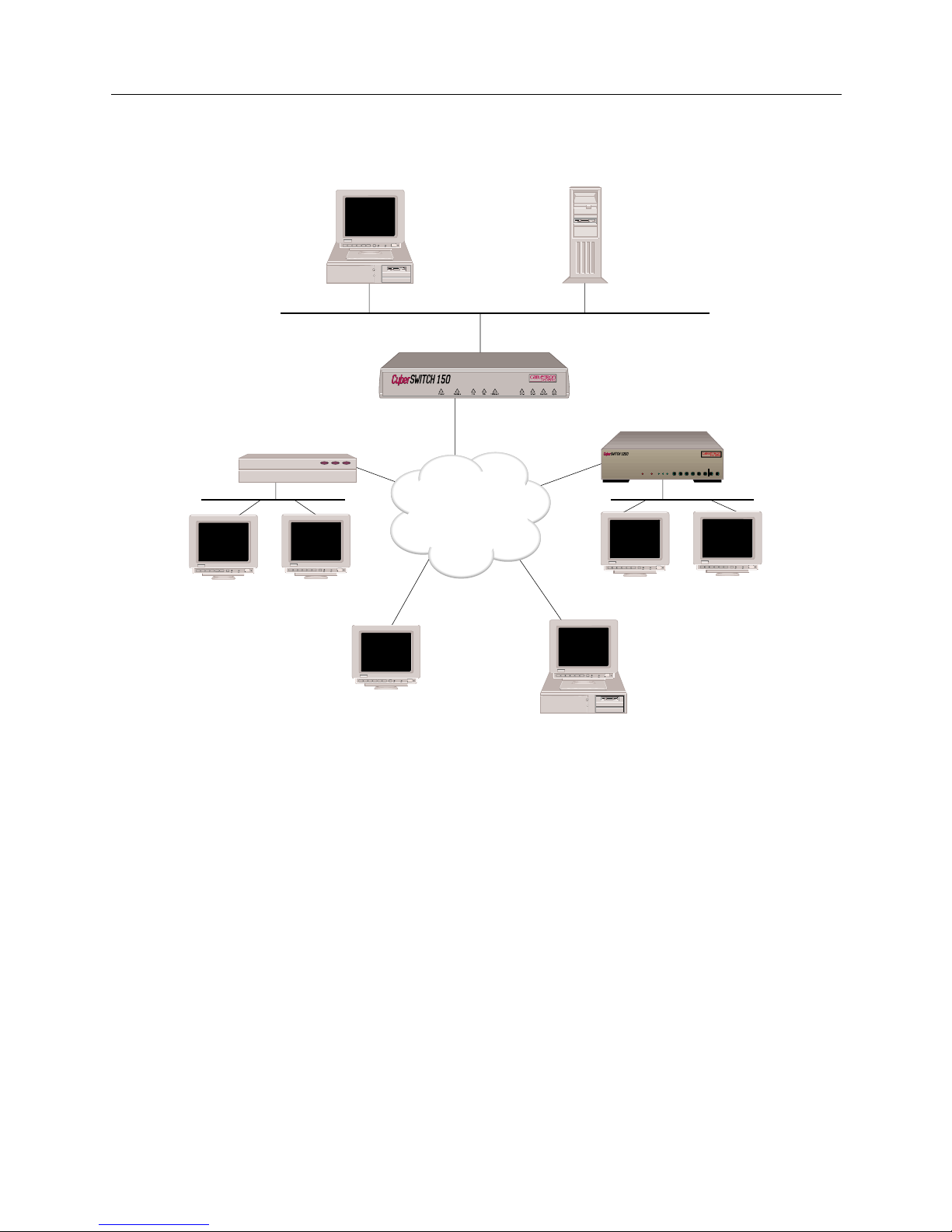
THE CYBER SWI TCH NETWORK
System software has been developed specifically for an embedded communications platform. It
uses a flas h file system (i nstea d of a hard disk) an d a two-st age boot device t o ini tialize t he plat form
and download the system software. The system software is preconfi gured to allow immediate
connect ion to a local area netwo rk (LAN) or a wide area net work (WAN) with Teln et and/or TFTP
access.
This system is geared toward the small office, offering a variety of internetworking capabilities.
Page 27
Small Office Remote Access Switch 27
THE C
YBER
SWITCH
Unique System Features
UNIQUE SYSTEM FEATURES
The CyberSWITCH combines unique features that improve cost-effectiveness, reliability, and
performance for wide area network connections to remote devices. These features include:
• Authentication Servers
Provide a central database for networks with more than one CyberSWITCH. The central
database consists of manageable, informatio nal data (refe rred to as the Device List or Device
Table). This data is acces sed and used for aut hentication when a n ew connection is esta blished
to the system.
• Bandwidth Agility
The system dynamically controls the bandwidth in use between itself and other PPP devices.
This is accomplished by estab lishing a nd dis c onn ecting calls . The num be r of calls is limited
only by the types and number of lines available. The system monitors the connections for
utilization and will add an d remove the connec tions based on use r- configurable throughput
parameters. As network ba ndw id th requirem ent s increa se or decrea se, the system will
ISDN
Host
File Server
Remote ISDN Bridge
Workstation
Workstation
PC
(with BRI ISDN TA)
BRI
BRI
Workstation
BRI
BRI
Workstation
Workstation
CSX150
B25B27
B26B28
WORKGROUP REMOTE ACCESS SWITCH
B29
E1 ONLYB-CHANNELS
LAN
10BASE-TRXTXSERVICE
B31
B30L1
B21B23
B22B24
B17B19
B18B20
B13B15
B14B16
E1DT1
D
B9B11
B10B12
B5 B7
B6 B8
B1 B3
B2 B4
POWER
Page 28

USER’S GUIDE
28 CyberSWITCH
automati cally adju st th e nu mber of ne twork con nect ion s. Thus, your n et work costs w il l ref lec t
the actual bandwidth being used.
• Filtering
Allows you to control the flow of frames through the network. Filtering becom es nec essary if
you need to re strict remote access or con trol widespread transmission of sp oradic messages.
Customer-defined filters can forw ard messages based on addresses, protocol, or packet data.
• Data Compressi on
Allows the system to negotiate compression algorithms with another device on the network.
After successfully negotiating compression, data is compressed by the remote device and
transmi tte d to the system. The system deco mp resses the data, processes the information
contained in the user data, and forwards the data as required. The system can receive data
coming over a WAN or a LAN, and compress the data before transmitting it to another device
on the network. The net ef fect is to i ncrease int erconnect bandwidth by de creasing
transmi ssion time. If negotiati on for compre ssion fails, data is transmitted uncomp ressed.
• Dial Out Capability
The system will dial out to remo te dev ices . Th is featur e allows the sy st em to accep t user data
receiv e d on the Ethernet LA N or I S DN network and initiate a data connectio n to the remote
device specified in the user data. This allows devices on the local LAN to initiate connections
to networks connected to the system ove r the switched digital network. The system monitors
the connection for utilization and will rem ove the connection when it becomes idle.
• Dynamic Management
Provides a “real- time” manageme nt mechan ism that allows many system p arameters to be
changed with out interrupti ng the current execution state of the system software. Th is feature
consists of a series of console comman ds that enable a user to displa y current system
paramet ers , c ha ng e man y par ame ter s d yna mica lly , and wri t e cha ng es t o d isk f il es s o th at the y
remain permanent.
• High Speed Digital Connections
The system supp orts 56Kbps and 64Kbps co nnections to remote locatio ns. These dial- up digital
connections provide re liable high throughpu t connections for effici ent data tran sf e r for the
same cost as analog connections. If any r e mote devices conn e cted to the system support multi-
link PPP, up to 32 parallel connections can be made at either 56Kbps or 64Kbps.
• IP Filters
The IP filters allow you to control the transmission of individual IP packets based on the packet
type. You can specify packet type by IP address (source or destination) or by IP protocol (TCP,
UDP, ICMP).
Once you specify a packet type, two forms of IP filtering are available:
• Forwarding Filters, applied at discrete points of the IP processing path to determine if a
packet continues its normal processing, and a
• Connection Filter, which determines if an IP packet requiring a WAN connection may continue.
•Packet Capture
In order to monitor incoming LAN data, the CyberSWITCH packet capture feature will allow
you to capture, display, save, and load bridged or routed data packets.
Page 29

Small Office Remote Access Switch 29
THE C
YBER
SWITCH
Interoperability Overview
• Protocol Discrimination
It is possible for multiple types of remote devices to use the same line. The system can
determine the device type and the protocol encapsulation used by remote devices.
• RS232 Port: Dual Usage
If your installation requires you to process PPP-Async data, this feature allows you to use the
RS232 port for either console acc ess or a serial data connection. This dual usage is possible
throu gh the Cyb erSWITCH’s s u pp ort of Aut o se nse mode and Te r m i n a l mo d e :
• Autosense mode determines whether you are trying to connect using a VT emulation or PPP-
Async, and connects you appropriately. (VT emulation requires you to perform four carriage returns to receive a login prompt.)
• Terminal mode assumes that you o nly wa nt to connec t usi ng VT emu latio n. A log in p rompt
is displayed as soon as the connec tion is made.
•Security
Security is a key issue for all central site network mana gers and is a priority with the
CyberSWITCHs. The modules provide high level features that help prevent unauthorized or
inadver tent acc ess to c riti cal data and reso urces. The mo dules su pport ex tensiv e secu rity lev els
including:
• PPP PAP and CHAP
• User n a me a n d pa ssword
• Calling Line ID (CLID)
• Ethernet Address
• User Authentication
• Device Authentication
• SecureFas t Virtual Remote Ac cess (SFVRA)
• TACACS Client with Radius Server
•RADIUS
• Security Dynamic’s A CE/SecurID
• Simultaneous Connections
The system su p ports si mu l ta n e o u s con nections to multiple l o ca t i on s. Thes e lo ca t i ons can
connect by using different channels on the same line, or they can connect on different lines. This
pooling of lines among many poten tial locations is more cost e f f e ctive than alternative poin tto-point lines.
INTEROPERABILITY OVERVIEW
“Interoperability” is the ability to operate and exchange information in a heterogeneous network.
The CyberSWITCH supports interoperability with many different remote devices over ISDN.
INTEROPERABILITY PROTOCOLS
In order to commun icate wi th vari ous remot e devic es over I SDN, the CyberSWI TCH must i dentif y
the device type and the protocol it is using.
The CyberSWITCH supports the following line protocols:
• HDLC Ethernet Frames
• Ordered Protocol for Ethernet Frames
• Point-to-Point Protocol (PPP) Encapsulation for IP Datagrams
Page 30

USER’S GUIDE
30 CyberSWITCH
The CyberSWITCH supports the following PPP protocols:
• Link Control Protocol ( LCP)
• Multilink Protocol (MLP)
• Authentication Protocols
Challenge Handshake Authen tication Protocol (CHAP)
Password Authentication Protocol (PAP)
• Network Con trol Protocols (NCP)
Interne t P rotocol Control Protocol for TCP/IP (IPCP)
Intern e t work Packet Exchange Co ntrol Protocol for IPX (I PXCP)
Bridge Control Pro toc ol for bridg es (BCP)
• Compressi on Control Pr otocol (CCP)
• AppleTalk Control Protocol (ATCP)
The CyberSWITCH supports the fo llowing AppleTalk protocols:
• EtherTalk Link Access Protocol (ELAP)
• AppleTalk Address Resoluti on Protocol (AARP)
• PPP AppleTalk/AppleTalk Control Protocol (ATCP)
• Datagram Delivery Protoco l (DDP )
• Routing Tab le Maintenance P rotocol (RTMP)
• AppleTalk Echo Protocol (AEP)
• Name Binding Protocol (NBP)
• Zone Inform ation Protocol (ZIP)
INTEROPERABILITY DEVICES
Remote devi ces that may conn e ct to the CyberSWITCH include the follow ing:
• MAC Lay er Bridges
•IP Host Devices
• IP Router Dev ices
• IPX Route rs
• AppleTalk Routers
MAC layer bridge s connec t to the syste m using the HD LC bridge encap sula tion line p rotoc ol .
These devi ces send transpar ently bridged E therne t frames to the sy stem. MAC layer br idges do not
process ne twork layer protocols. The y forward all packets based on source and destinati on MAC
addresses.
IP Host devices are single workstations or PCs that co nne ct to the system at the IP network layer.
These devices use either the RFC1294 based protocol or PPP to communicate with the system.
IP router devices are single devices that represent many ot her IP hosts and ro uters to the syste m.
They must use the CHAP or PAP protocol to identif y themselves to the system. IP routers usually
provide IP network address information at connection time (and use PPP to send user data to the
system).
IPX routers are single devices that perform network layer tasks (addressing, routing, and
switchin g) to move packet s from one loca tion on the network to another. IPX routers use the
Internetwork Packet Exchange (IPX) protocol, typical of the NetWare environment.
AppleTalk routers route AppleTalk datagrams based on address information. They support the
following protocols: RTMP, NBP, and ZIP.
Page 31

Small Office Remote Access Switch 31
THE C
YBER
SWITCH
Security Overview
SECURITY OVERVIEW
The system provides several options for validati ng remote dev ices and for managing network
security. The security options available are dependen t on the remote device type, type of access ,
and the level of security required.
Levels of security include no security, device level security, user level security, and multi-level
security. Device level security is an authentication process between devices, based on protocol and
preconfigured information. Sec urity information is configured either in the system’s On-node
Device Dat abase, or in a ce ntral database such as the VRA Mana ger. Here the network
administrator specifies all of the security inform ati on for each indiv idua l user. A portion o f this
information is used to identify the remote device. The remaining data is used to perform user
validation after user i dentificati on has been comple te d.
User level security is an interactive process. It is currently supported on the system through the
TACACS or ACE server programmed for use with security to ken cards. With user leve l security,
the potential network user explicitly connects to the server and must properly “converse” with it
in orde r to co n ne c t with oth e r de vi c e s b e y o nd the serv er .
Import ant to user level authentication is th e se curity token card. Th is card, programmed in
conjun ction with the au thentication server, generates random passwords. These passwords must
be supplied correctly at syst em login tim e, or acces s to the networ k will be den ied. The secur ity
token cards should be issu e d to each user on the network to properly maintain system inte grity.
Multi-level security provides device level security for all remote devices. Individual devices may
be configu red for user level authentication as well. In this case , device le ve l authentication takes
place between the system and the remote device. Then a specific user must initiate user level
authentication by sta rting a Telnet session. Both levels of authenti cation must be satisfied before
traff ic can pass.
NETWORK INTERFACE OVERVIEW
The network interface is the physical connection of the CyberSWITCH to a data network. For
example, the Ethernet resource in the system provides a net work interface to an Ethernet LAN. The
ISDN lines in th e s yste m prov i de netw ork i nter fac es t o mu ltip le r emote net wor ks. Beca use of th eir
switched nature, the ISDN lines provide virtual network interfaces. That is, the same physical ISDN
line can actually c onnect to different remote networks by d ialing a different phone number.
The CyberSWITCH provides a set of network interfaces that give you a wide range of flexibility.
The network interfaces provided by the system are:
• LAN IP Network Interface
• LAN IPX Network Interface
• WAN IP Network Inte rface
• WAN (Direct Host) IP Network Interface
• WAN RLAN IP N etwork Interface
• WAN RLAN IPX Network Interface
• WAN (UnNumbered) Network Interface
Page 32

USER’S GUIDE
32 CyberSWITCH
SYSTEM COMPONENTS
The majo r co m p o ne nt s of th e CyberSWITCH are :
• System hardware consisting of a platform and an administration port provided by the
platform.
• Four main categories of system software:
The boot device gains control at power-up. It runs diagnostics, downloads new versions of
operational softwa re , and prepares the host processor for execution of operational so ftware.
The flash file system stor e s a compressed image of operational software an d I/O system
software. It also stores other necessary files for configuration and information storage.
The operational software provides system functionality, such as download and initialization of
the I/O subsystem. The I/O subsystem handles LAN I/O.
• Remote I S DN devices wh ich inter op e rate with the system and allo w device access to n e twork
resources.
More deta iled desc ripti ons of sy stem so ftware an d hardwar e are included in the nex t two chap ters .
The following section describes remote ISDN devices.
REMOTE ISDN DEVICES
The CyberSWITCH provides a centralized concentrator function for remote ISDN devices. The
devices can be separated into the following categories:
• remote ISDN bridge devices
• PC based terminal adapters
• ISDN enabled workstations
• other ISDN routers
Typical remote ISDN bridges provide one Ethernet port and one basic rate ISDN port. The basic
rate port is connected to the switched digital network and is used to make connections to the
CyberSWITCH. The Ethernet port is used to connect to a remote LAN. The remote bridge device
sends Ethernet frame s from devices on the remote LAN over the switched network.
PC-based terminal adapte rs connect to a remote personal compute r an d us e the switche d d igital
network to con nect to the system. The terminal ad ap te r sends network protocol specific frames
from the host PC device over the switched network.
Workstat ion-based terminal adapters connect to a work station and use the switched digi tal
network to con nect to the system. The terminal ad ap te r sends network protocol specific frames
from the wor kstation over the switch e d network.
Page 33

Small Office Remote Access Switch 33
THE C
YBER
SWITCH
Switches Supported
SWITCHES SUPPORTED
Switch types supported by the CyberSWITCH’s basic rate and primary rate ISDN adapters:
Switch support may vary from country to country. Use the following as a guideline:
Type of Switch Basic Rate Primary Rate
AT&T #4ESS NA Yes
AT&T #5ESS Yes Yes
AT&T Definity Yes Yes
AT&T Legend Yes NA
NET3 Yes NA
NET5 NA Yes
NT DMS 100 Yes Yes
NT DMS 250 NA Yes
NT SL-100 Yes Yes
NTT Yes Yes
NI-1 Yes NA
TS013 Yes NA
TS014 NA Yes
1TR6 Yes Yes
Country Switches supported
(BRI lines)
Switches supported
(PRI lines)
Australia TS013
NET3
TS014
NET5
Germany 1TR6
NET3
1TR6
NET5
Japan NTT NTT
United States AT&T 5ESS
AT&T Definity
AT&T Legend
NT DMS 100
NI-1
AT&T 4ESS
AT&T 5ESS
AT&T Definity
NT DMS 100
NT DMS 250
NT SL-100
International NET3 NET5
Page 34

H
ARDWARE OVERVIEW
The Cybe rS W I TC H is an embedded communications platform. It uses a fl ash file system (instead
of a hard disk) an d a two-stage boot device to initialize the platform and downl oad system
softwa re. System software is preconf igured to a llow immediate connection via a Local Area
Network (L AN) or Wid e Ar ea Ne two rk (WAN) wi th Te lnet and/ or TF TP a ccess. T he s oft ware can
also be accessed via the RS232 port on the system, and a te r minal - emula tio n so f tware p a ck a ge .
The CyberSWITCH is ideally suited for the s mall offi ce or home office, providing high speed IS DN
connectivity to centralized networks or the Internet. From a remote si te , the System all ows you to
access corporate LANs as easily as others at the corporate site, using cost-effective high-bandwidth
internetworking technology. The System also offers a Plain Old Telephone Service (POTS)
interface, which supports up to two telephone-type devices, includ in g standard phones, modems,
fax machines, and answering machines. The Sy ste m’s POTS service supports tone dialing only.
System features include:
• a direct Ethernet 10Base-T connection
• optional 10Base-2 (BNC) connection
• a direct ISDN connection
• bridge or router capabilities
• bandwidth management
• data co mpres s ion
• dual POTS interface
• remote ad ministration
• remote upgrades
This chapter include s safe ty conside r a tions and a des crip tion of Sma ll O ffice Cybe rSW ITCH
platforms.
SAFETY CONSIDERATIONS
The CyberSWIT CH contains a lith ium battery to sup p ort its time-keeping functi ons. It is a longlasting battery, and was not intended to be user-replaceable. In the unlikely event that you have a
problem wi th the batte ry , contact your distributor for replacement.
CAUTION: Danger of explosion if battery is incorrectly replaced. Replace only with the same or
equivalent type recommended by the manufacturer. Di scard used batteries according
to the manufacturer’s instructions.
Page 35

Small Office Remote Access Switch 35
H
ARDWARE OVERVIEW
System Platforms
SYSTEM PLATFORMS
The CyberSWITCH platform consists of a single processor (the Intel 386 E X host process or), system
memory, an d i nterface adapte rs. The front of the platform has a series of LED indicators. These
indica t or s li g ht u p to indicat e po we r , se rvice , LAN acces s , and WAN ac ce s s. On the ba ck of the
platfor m are connectors f or power, the LAN, the WAN, a RESET butto n, and an administ ration port
for local or remote administrati on console attachment.
Currently, the following CyberSWITCH models are available:
CYBERSWITCH CHARACTERISTICS
Physical Char acteristics:
Height: 38.1 mm (1.5 in)
Width: 177.8 mm (7 in)
Length: 177.8 mm (7 in)
Weight: approximately 672 g (1.5 lb)
Environmental Characteristi cs:
Operating Temp: 0° to 40° C (32° to 104° F)
Operating Humidity: 5–95% non-condensing
Operating Altitude: 3000 m maximum (10,000 ft maximum)
Non-operating Shock: 30 G, 11 ms, 1/2 sinewave
Storage Temperature: -40° to 85° C (-40° to 185° F)
Electrical AC Power Input (External Power Supply):
Voltage: 90–264 V AC
Frequency: 47–63 Hz
Power: 25 watts
Regulatory Compliance:
Meets or exceeds the following:
Safety: UL 1950, CSA C22.2 No. 950, EN 60950, IEC 950,
and 72/23/EEC
EMI: FCC Part 15, EN 55022, CSA 108.8, EN 50082-1,
VCCI V-3, and 89/336/EEC
POTS Characteristics:
compliant with: A NSI/EIA/TIA-464-A-89
supports phones
compliant with: ANSI/EIA-470-A-1987
Model Mode of Operation Features
CSX154 multiprotocol route r • supports o ne or two c oncurrent
protocol stacks plus bridging
• complete feature support
CSX155 multiprotocol route r • supports o ne or two c oncurrent
protocol stacks plus bridging
• complete feature support
• internal NT-1
Page 36

USER’S GUIDE
36 CyberSWITCH
CYBERSWITCH SERIES
Front & Back Panels:
Back Panel as illustrated suppo rts:
• Wide Area Network (WAN) through 1 BRI line, two connections
• Local Area Network (LAN) through the 10Base-T Ethernet port or th r o u g h the 1 0Base2 Ethernet port
• analog de vices (up to two) through the dual POTS interf ace
C
YBERSWITCH
FRONT PANEL
The front panel of the system has several LED indicators. These include:
• Power - remains lit while the unit is on.
• Service - denotes something needs attention in the syste m. The only red indicator.
• The LAN indicators: TX, RX, and 10BaseT. T hese ligh t to in dica te t ransm issi ons, rec epti ons, or
good link integrity on the 10Base-T port.
• The WAN indicators: CH-1, CH-2, D-Chan, and Sync.
When Sync is lit, it indicates the line is connected and sync hroniz ed .
When D-Chan is lit, it indicates the D channel is up and operational.
When CH-1 or CH-2 blinks, it indicates data traffic on the spec ific ch anne l.
When CH-1 or CH-2 is lit continuously, it indicates that a call has been established.
For more detailed LED indicator information, refer to the LED Indicators chapter.
BRI Term 10BT 10B2 Console DCPower Reset
1 2
Termination switches for
Multipoint Connections
WAN
Port
Ethernet
LAN Port
(
twisted pair
)
Dual
POTS
LAN Port
(thinwire coax)
Console Port / AMP
Small Office Remote Access Switch
Page 37

Small Office Remote Access Switch 37
H
ARDWARE OVERVIEW
System Platforms
CYBERSWITCH BACK PANEL
The back panel provides connectors for WAN and LAN access, as well an RS232 port for an
administration console. It also contains termination switches, a DC power input connector and a
Reset button.
The two connectors available for LAN access are the 10Base-T (RJ-45 Ethernet connector) or the
optional 10Base-2 (Ethernet BNC connector). Only one of the two ports may b e activa te d at a time .
If you attempt to use both, the syste m ha rdware au tomatica lly de faults to the 10Base-T port.
The back panel also provides WAN access via an RJ-45 ISDN interface connector for a BRI line. This
interface supports 2B + D channels, with each of the two B channels capable of providing either
56Kbps or 64Kbps digital transmission.
To the right of the BRI connector is a pair of termination switches for multipoint connections. These
switches are labeled Term. These DIP switches control the terminating resistors for the Ba sic Rate
Interface.
You must set both switches in the same direction or improper operation may result. The small
arrow points in the direction of the on position. When the switches are on, the resistors f or the
connector are providing termination for the BRI line. Conversely, when the switches are off, the
resistors for the connector are not providing termination for the BRI line.
On an S/T interface, it is important to have the termination switches set correctly. On a U interface,
the circuitry is intended to operate properly no matter which setting is used; however, optimum
operation is achieved with the switches off.
The Console connector (an RS232 connector) provides an asynchronous connection for
administration console management, or PPP-Async data transfer.
The power input comes from the provided external power supply, which attaches to the DC Power
connector. Voltages required are +5 volts DC and +12 volts DC.
Note that there is no POWER switch on the back panel. The system has been designed to run
continuously in order to support the Plain Old Telephone Service (POTS) interface. In the event that
the CyberSWITCH is accidently unplugged, you must press Reset once power is reconnected. In
the event you must disconnect the unit from its power supply, unplug the power cord from the wall
(the AC connection) first. Do not remove the DC power input (attached to the CyberSWITCH)
before disconnecting at the wall.
The Reset button is a small, recessed button on the right side of the b ack panel. To reset the unit,
use a pen or a sharp pencil to depress the button.
The RJ-11 connectors for the dual Plain Old Telephone Service (POTS) interface, are identified by
telephone icons, and are labeled 1 and 2.
Page 38

USER’S GUIDE
38 CyberSWITCH
For informational purposes, here are the pin list and sig nal assignments f or the 10Base-T LAN
connector:
Note: T he 10Base -T con necto r an d the W AN conn ect or are both RJ 45 con ne ctors . Ho wever , they
do have different electrical interfaces. Take care to keep these separate.
Pin Signal Function
1 Transmit +
2 Transmit -
3 Receive +
4 NC No Connect
5 NC No Connect
6 Receive -
7 NC No Connect
8 NC No Connect
Page 39

S
OFTWARE OVERVIEW
OVERVIEW
The Cybe rS W I TC H so ft wa r e pro v ide s :
• system so f tware for the CyberSWITCH, LAN and WAN interfaces, and admini stration
function s
• system files containing configuration and operational information
This chapter provides an overview for each of the above software categories.
SYSTEM SOFTWARE
Included with each CyberSWITCH is a CD containing upgrade software and utility software. (Note
that initial system software is factory-installed). The following system software files are available
on the CD:
upgrade.osw
All the system files needed for upgrading the CyberSWITCH are combined in this file.
defltcfg.osw
All of the system files needed to return your system configuration to the factory default are
combined in this file.
SYSTEM FILES
The CyberSWITCH uses a flash file system (instead of a h ard disk) and a two-stage boot d e vice to
initialize the platform and download the system software. The flash file system basically performs
the same as a ha rd d isk, b ut it ha s n o dr ive l et ter . Just as on a har d disk, t he f lash fi le has dir ect ories
with files.
CONFIGURATION FILES
The configuration files store the configuratio n da ta. These files are located in the sy ste m’s
\config directory. You can maintain these files by using the CFGEDIT configuration utility,
which is delivered with the system. You can also make changes to these fil e s through Manage
Mode.
The configuration files associated with the system are:
network.nei
This configuration file contains info rma tion about the switched netw ork.
devdb.nei
This file contains the On-node Device Database configuration information about each remote
device.
Page 40

USER’S GUIDE
40 CyberSWITCH
node.nei
This configuration file contains node -spec if ic informat ion like resou rce s, lines, Cybe rSW ITC H
operating mode and secur ity options, along with the Throughput Monitor Configu ration
information. If enabled, SNMP configuration information is also in this file.
lan.nei
This file contains configuration information used when the bridge is enabled. This file also contains
information for the Spann ing Tr e e protoco l used for the bridge. Information from this file is
configured and used only when the bridge is enabled.
ip.nei
This file contains configuratio n info rma tion used when th e IP routing is enable d. This file also
contains information regarding network interfaces, RIP, and static routes. Information from this file
is configured and used only when the IP routing is enabled.
ipx.nei
This file contains configuration information used when the IPX routing is enabled. This file also
contains information regarding network interfaces, RIP, and static routes. Information from this file
is configured and used only when the IPX routing is enabled.
filter.nei
This file contains all filter configuration information (bridge, hardware, and IP). This file is new to
Release 7.2 software, but is compatible with previous software versions, which contained filter
information in the lan.nei and/or ip.nei files. With Release 7.2 configuration changes and
configuration file updates, this filter information will be moved to filter.nei.
atalk.nei
This file contains configuration information used when AppleTalk Routing is enabled. This file also
contains information regarding ports and static routes. Information from this file is configured and
used only when the AppleTalk routing is enabled.
sdconf.rec
This is not a system file; it is a configuration file delivered on the ACE Server. However, you may
TFTP th i s file to th e sy st e m’s \config directory as an alternate method of providing the system
with ACE Server configurat ion inf ormat ion.
OPERATIONAL FILES
While the Cyb e rSWITCH is running, it col lects syst em statistic s and logs system me ssages. The
system maintains these statistics and messages in two separate memory-resident tables. The ten
most recent versions of each table are available on the system disk.
You can re t ri eve and vie w the current mem o ry- reside n t ta bl e s a t an y tim e by u sing the fo llowing
console commands:
dr
This command will display system messages.
ds
This comma nd will display system stat istics.
You can write the tables to disk by using the following commands:
wr
This command will wri te the curren t system mess ages to disk.
ws
This command will wri te the curren t system statistics to disk.
Note: When the system is shut down, the tables are automatically written to disk.
Page 41

Small Office Remote Access Switch 41
S
OFTWARE OVERVIEW
System Files
The system stores the tables in ASCII format files on the System disk. When the system writes
system messages to disk, it stores the m in the following location:
Directory: \log
File Name: rprt_log.nn
Where “nn” is an integer that is incr ement ed e ach time a new file is written.
When the system writes system statisti cs to disk, it stores them in the following locations:
Directory: \log
File Name: stat_log.nn
Where “nn” is an integer that is incr ement ed e ach time a new file is written.
USER LEVEL SECURITY FILES
As administrator, you may create a welcome banner file as well as a message-of-the-day fil e to
display at login with user level security. Neither file should exceed the limits of 80 characters in
width and 21 lines in length, and must reside in the \config directory. The creation of these files
is option al; if you choose to use them, create the files, and TF TP them to the CyberSWITCH.
welcome.nei
This file co ntain s the text of the admini strat or-defi ned wel come banner. It is displ ayed whe n a user
initiates a network login.
motd.nei
This file contains the text for t he administrator-defined message of the day. It is di splayed when the
user is validated after log-in.
Page 42

S
YSTEM INSTALLATION
We include the followin g chap ter s in this segment of the User’s Guide:
• Ordering ISDN Servic e
Provides guidelines for ordering ISDN service in the United States.
• Hardware Installation
Step-by-step instructions for installing hardware components.
• Accessing the CyberSWITCH
Provides a description of the possible ways to access the CyberSWITCH (for diagnostic
purposes or for software upg rad e s).
• Upgrading S ystem Software
A description of the software upgrade process.
Page 43

O
RDERING
ISDN S
ERVICE
(US O
NLY
)
OVERVIEW
This chapter was designed to be a guideline f or orderin g ISDN serv ice in the United Stat es.
If you are using NI-1 lines, try using EZ-ISDN Code s to order BRI service. If your service provider
does not support EZ-ISDN Codes, try using the NI-1 ISDN Order ing Co de s .
If your ser vice prov iders do es not su pport ei ther type s of codes , or, if you are usin g a non-NI-1 l ine,
refer to Ordering BRI ISDN Lines using Provisioning Information.
ORDERING NI-1 LINES USING EZ-ISDN CODES
If you are using a NI-1 switch type and your service provider supports EZ-ISDN codes, we
recommend using the EZ-ISDN 1 code. EZ-ISDN 1 provid es alternate circuit-switched voice/data
on both B-Channels. There is a CSV/D terminal associated with each of the B-channels.
The B-channels will be given a unique primary directory number capable of making/receiving one
circuit-switched voice or circuit-switched data call. Additionally, calling line Id and additional call
offering (ACO) are also su pp orted . ACO is req uired to allow inc oming voice calls to optionally
preempt or disconnect remote d ata devices (refer to POTS configuration information and to POTS
configuration elements definitions).
ORDERING NI-1 LINES USING NI-1 ISDN ORDERING CODES
If you are using a NI-1 switch type and your service provider supports ordering codes, use this
section when ordering your ISDN line. We provide recommended NI-1 ISDN ordering codes each
category of CyberSWITCH remote device.
FOR NON-POTS DEVICES
If you have a system without the POTS option, w e recom m end NI-1 ISD N Capa bilit y Packag e I.
This package includes circuit-switched data on two B channels. Data capabilities include Calling
Line Id. No voice capabilities are provided. The lack of voice feature may save you money.
However, package K or M will also work.
FOR SINGLE POTS DEVICES
If you have a system with a single POTS connection, use Capability Package K plus the ACO option
(additional call offering). Capability Package K includes alternate voice/circuit-switched data on
one B channel, and circuit-switched data on the other B channel. This package provides non-EKTS
voice features, including Flexible Calling, Additional Call Offering, and Calling Line Id. Data
capabilities include Calling Line Id. The ACO option allows an incoming POTS call to disconnect/
preempt a data call if enabled. If you do not wish to use this feature (i.e., you are not using i ncoming
preemption), dropping ACO may lower your costs.
Page 44

USER’S GUIDE
44 CyberSWITCH
FOR DUAL POTS DEVICES
If you have a system with a dual POTS connection, use Capability Package M, plus the ACO option.
Capability Package M includes alternate voice/circuit-switched data on two B channels. Data and
voice capabilities include Calling Line Id. The ACO option allows an incoming POTS call to
disconnect/preempt a data call if enabled. If you do not wish to use this feature (i.e., you are not
using incoming preemption), dropping ACO may lower your costs.
ORDERING BRI ISDN LINES USING PROVISIONING SETTINGS
If your service provider does not su p por t EZ- IS DN or ISDN Order ing Co de s , or you a re usin g a
non-NI-1 line, use this section when ordering your BRI ISDN line.
When the phone company installs the line, they assign it certai n characteristi cs. These are differ ent
depending on the type of ISDN switch to which the line is attached. AT&T’s 5ESS NI-1 and
Northern Telecom’s DMS100 NI-1 are among the most popular.
When ordering an ISDN line, there are general steps to follow that apply to all types, and there are
steps specific to your line type. The general steps to follow are:
1. Contact your service provider to determine the type of available switch.
2. Ask your service provider for the available types of ISDN services.
If the AT&T 5ESS switch type is available, the ISDN services available will be one of the
following:
•NI-1
• Custom Poi nt-to-Point
If Northern Telecom DMS-100 switch type is available, the ISDN services available will be one
of the following:
•NI-1
• DMS-100 Custom
3. Refer to se ction in this document that applies to you r se rvice type .
4. Order your ISDN service. If available, ask for two telephone numbers and two SPIDs for your
ISDN line.
5. If necessary, provide your service provider with the appropriate provisioning settings in this
document.
6. After installation, make sure you have the following information:
• switch type
• telephone numbers
• SPIDs
The following sections provide provisioning settings for your specific service type.
Page 45

Small Office Remote Access Switch 45
O
RDERING
ISDN S
ERVICE
(US O
NLY
)
Ordering BRI ISDN Lines using Provisioning Settings
PROVISIONING SETTINGS FOR AT&T 5ESS SWITCHES
The ISDN services supported by AT&T 5ESS switches are as follows (in order of preference of
usage):
1. NI-1
2. AT&T Custom Point-to-Point
The sections below provide t he settings f or each 5 ESS servic e type. Note t hat your service provider
may not be able to of f e r all of the features listed.
AT&T 5ESS NI-1 S
ERVICE
Note that some of the elements b elow are set per di rectory number. With NI-1 Se rvice, you will
typica l ly ha ve two dire c to r y numbe r s.
AT&T #5ESS NI-1 Service
Prov isionin g E l e ment Setting
Term Typ e A
CSV 1
CSV ACO unrestricted
CSV limit 2
CSV NB limit 1
CSD 1
CSD ACO unrestricted
CSD limit 2
CSD NB limit 1
EKTS no
ACO yes
Page 46

USER’S GUIDE
46 CyberSWITCH
AT&T 5ESS CUSTOM POINT-TO-POINT SERVICE
Note that some of the elements b elow are set per di rectory number. With Custom Point-to-Point
Service, you will have two directory numbers.
PROVISION SETTINGS FOR NORTHERN TELECOM DMS-100 SWITCHES
The ISDN services supported by Northern Tele com DMS-100 swit ches are as follows (in order of
preference of usage):
1. NI-1
2. Custom Service
The sections below provide the settings for each DMS-100 service type. Note that your service
provider may not be able to offer all of the featur e s listed.
AT&T Custom Point-to-Point Service
Prov isionin g E l e ment Setting
Term Typ e A
CA 1
CA quantity 1
CSV 1
CSV limit 2
CSD 1
CSD limit 2
Page 47

Small Office Remote Access Switch 47
O
RDERING
ISDN S
ERVICE
(US O
NLY
)
Ordering BRI ISDN Lines using Provisioning Settings
NORTHERN TELECOM DMS1 00 NI-1 SERVICE
Note that you mu st set either EKTS or ACO to yes. You may not set both of them to yes.
Northern Telecom DMS100 NI-1 Service
Provisioning Element Setting
signaling functional
PVC 2
TEI assignment dynamic
maxkeys 3 is preferable
1-64 is acceptable
release key no
ringing indicator no
EKTS no
ACO yes
number of call
appearances
2 is standard
number may vary depending
on voice features ordered
notification busy limit 1
(always one less than number
of call appearances)
LCC ISDNKSET
Page 48

USER’S GUIDE
48 CyberSWITCH
NORTHERN TELECOM DM S100 CUSTOM SERVICE
Note that you mu st set either EKTS or ACO to yes. You may not set both of them to yes.
Northern Tel ecom DMS100 Custo m Service
Provisioning Element Setting
signaling functional
PVC 1
TEI assignment dynamic
maxkeys 3 is preferable
1-64 is acceptable
release key no
ringing indicator no
EKTS no
ACO yes
number of call
appearances
2
LCC ISDNKSET
Page 49

H
ARDWARE INSTALLATION
PRE-INSTALLATION REQUIREMENTS
Before you begin the installation process, be sure to:
• Choose a suitable setup location
Make sure the location is dry, ventilated, dust free, static free, an d free from corrosive
chemicals
• Verify system power requirements
The appropriate standard power cord is supplied with the system. The power supply will
accept any input voltage from 85 to 264 volts without the need to select a voltage range.
• Verify cabling requir ements
The cabling shipped with your system should include:
• BRI/PRI/LAN patch cables, 5 meters each.
• RS232 cable, 1.8 meters. This is for the console por t. This cable is a 9-pin female to 9-pin
female nu ll mo dem cabl e . Jack sc re ws are included.
Note: The BRI/PRI/LAN cables are straight-through CAT5 patch cables. The quantity
shipped varies, based on device requirements. Th ese ca ble s ar e not d istin guish ed
from each other in the carton.
We provide a cable for the 10Base-T port since it is typically used for the LAN connection.
However, if you plan to use the A UI port instead, you must provide your own cabling a nd
MAU for this connection. If you need additional cabling (other than what was shipped),
contact you r distributor.
• Verify administration console requirements
There are several ways to connect an administrative console to the CyberSWITCH. For
more information , refer to the Cabling se ction o f the Quick Start.
Voltage Range Current and Frequency
85-264 V .6 A
47-63 Hz
Page 50

A
CCESSING THE CYBER
SWITCH
OVERVIEW
This chapter describes acc essing yo ur Cyber SWIT CH , w hich includes:
• making proper connections
• establishing an administ ration session
• powering on the system
• accessing Release Notes
MAKING CONNECTIONS
There are a numbe r of way s to make a connection to the system, which include:
• direct connection usi ng a termi nal
• null-modem connection using a null-modem cable and a PC
• remote connection us ing Telnet
All connections but the Telnet connection use the serial port (labeled COMMPORT or Console) on
the back of the sy stem. The Telnet connection is made through the syst e m’s ISDN line.
DIRECT CONNECTION
This is t he simp lest co nnecti on; you merel y connec t up an A SCII ter minal to the Co nsole por t. Ho wever, thi s method can only b e used to configu re or man age the sy stem. To install or upgrad e system
software, you must u se the null-modem connec tion.
NULL-MODEM CONNECTION TO A PC
To inst all or upgrade system software, you must use a PC or workstation to connect to the system.
Since the CyberSWITCH does not have a CD-ROM drive, you mus t upgrade or i nstal l the software
through an attached PC, UNIX workstation, or any device that meets the f ollowing requirement s:
• has a CD-ROM drive
• provides an RS232 terminal program
• has X-Modem communications capability (required for software upgrade only)
• has ASCII transfer capability (required for SSB recovery)
Any computer or terminal that meets these requirements and connects to the administrat ion port
on the syste m can op e rate as an administration console.
Page 51

Small Office Remote Access Switch 51
A
CCESSING THE CYBER
SWITCH
Making Connections
Using the provided RS232 null modem cable, attach an administration console to the
CyberSWITCH. The administration port is a 9-pin, male RS232 serial adapter as shown below:
Connect one e nd of a null modem cable to the console port on the Cybe rSWITCH, and the other
end to the communication port on the PC. On the PC you must then execute a communication
package to emulat e a terminal (VT100). Your communication package should suppor t file transfer
(Xmodem a nd ASCII) for software upgrades and installation s.
Use the following default values for your communication package:
Baud rate 9600
Parity None
Data b its 8
Stop bits 1
Duplex Full
BRI Term 10BT 10B2 Console DCPower Reset
1 2
Console DCPower Reset
To PC
Null Modem Cable
Female DB9
Connector
Null Modem Cable
Female DB9
Page 52

USER’S GUIDE
52 CyberSWITCH
CHANGING THE BAUD RATE
The baud rat e is change able. The d efault r ate perfor ms well for config uration ch anges. A faster rate
is useful, however, to download new software upgrades to your system.
To change the b aud rate throu gh CFGEDIT:
1. Select Physical Resourc es from the main menu.
2. Select Data Line from the physical resources menu.
3. Follow the i nstructions to make changes to the ASYNCMDM.
4. When asked, enter the baud rate you want to use.
5. Step through the remaining parameters. The last entry will ask you if you would like to save
your cha n ges. An swer yes.
6. To make the new baud rate effe ctive, restart the system (with the
restart
command).
7. Change the communications package you are using to the same baud rate.
REMOTE CONNECTION USING TELNET
You can access the CyberSWITCH with Telnet. To do this, you must use Telnet client software.The
CyberSWITCH has default IP addresses configured to allow Telnet access. The default LAN IP
address is 1.1.1.1. To access the CyberSWITCH you must set the device’s IP address to be on the
same subnet as th e CyberSWITCH. We recommend that you use 1.1.1.2 and do this on a LAN that
is not connected to the internet. Then place the CyberSWITCH on the LAN and Telnet to the
address.
This default address allows immediate access to the system for installation purposes. Be sure to
change this I P address as soon as possible to one on your local subnet .
Note: Do NOT p lac e mo re than one Cybe rSWIT CH on a LAN wi th the defa ult set ti ng. W ith bo th
having the same IP address, unpredictable results will occur.
You may also Telnet in via the WAN connection. The general procedures are:
1. Connect th e sy stem to the (WAN) ISDN line.
2. From a remote device that supports unnumbered IP connections, dial in as a PPP CHAP device
USER1 (USER1 as sec ret). Provide Telnet with the CyberSWITCH address.
3. From a re mote device only supporting numbered IP connections, set up an IP Address 2.2.2. 3
and have it dial as a PPP CHAP device USER2 (USER2 as secret). Provide Telnet with the
CyberSWITCH address of 2.2.2.2.
After you make a Telnet connection, you will be present ed with a login prom p t. Proceed to
Establishing an Administrative Session.
For more information on Telnet, refer to the Remote Management chapter.
Page 53

Small Office Remote Access Switch 53
A
CCESSING THE CYBER
SWITCH
Establishing an Administration Session
ESTABLISHING AN ADMINISTR ATION SESSION
If a login prompt is di splayed after the power-on initialization, the system software was preinstalled.
Comp l e te the logi n:
1. The login controls which class of commands the user can access. Each access level (guest or
administrator) is protected by a unique login password. This allows managers to assign
different responsibility levels to their system users. Enter the following login:
admin
Note: W hen usi ng off-node authentication, administration acce ss level actually supports up to
101 different login names, from admin and ad mi n0 0 to admin99. These different login
names must be configured on the off-node server in order to function properly. For
local a dminist rati on acces s, onl y the guest and the singular admin login access levels are
valid.
2. All preinstalled systems are preconfigured with the same password. This is the password th at
is used the first time a login occurs. U si ng all lowercase letters, enter the preconfigured
password a s shown b e low:
admin
3. It is recommended that the preconfigured password be changed to a user-defined password.
To do this, e nter the foll owing command at the system prompt:
pswd
Follow the prompts to c hange the current password. A password must be a 3 to 16 nonblank
character string. Passwords are uppercase and lowercase sens it i ve.
Note: User-level security is not available at time of initial installation and configuration.
However, once this option is configured, you will have additional security steps before
establi shing an administrative session. Refer to Responding to LOGIN Prompts in the
Configuring Security Level chapter for more information.
If a DOS pr ompt is di spla yed after the power-on initialization, the software has not been preinstalled.
You must first boot up wi th diskette #1 before conti nuing:
1. Inser t software diskette #1 into the system diskette drive.
2. Reboot the Cyb e rSWITCH.
At this point, if you need to install new or upgraded software, refer to the Upgrading System Software
chapter. I f s oft ware has be en pr eins tall ed by yo ur di stri butor , s kip to Configuration Tools chapter to
begin the configuration process.
POWERING ON
1. Plug t he syst em’s powe r cord into a grounded elec trical outlet. An appr opriate standar d power
cord is supplied with the system for your specific country.
Page 54

USER’S GUIDE
54 CyberSWITCH
2. Turn on the administration console, and execute the communications program so that your
terminal emulator ac cesses the RS232 port connected to the system.
3. During power-on initialization, the First Stage Boot (FSB) displays a brief inventory of the
system. The FSB then writes the following message to the administration console:
Waiting for Commands:
During initial installation, no commands need to be entered at this point. Once this message is
displayed, the system waits 10 seconds before proceeding with the Second Stage Boot (stored
in flash memory ). If th is me ssag e is not displ a yed, and th e Serv ice LE D is blink ing, refe r to t he
LED Indicators chapter f or in st ru c tions.
4. When the Second Stage Boot (SSB) begins executing, it performs a series of diagnostic tests
called the power-on sel f tests (POSTs) . Nothing is displayed while these test s are running
unless a failure is detected. In the unlikely event of a failure, messages are displayed on the
console screen. Imme di ately after the POSTs have be e n c ompleted, a summ ary of availa ble
resources and syste m info rma tion is displa yed sim ilar to the follow ing:
If no First Stage Boot commands were e ntered, and valid system software is detected , the
Second Stage Boot begins to load the system software. Dots (...) are displayed to indicate
progres s. The display will look like th e f ollowing:
5. Log-in and passw ord p rom pts will be displ ayed after completion of power-on initia liz ation
(approximately 15 sec on ds after the “Booting Syste m Softw are” message):
The log-in for the system controls which class of commands users can access. A unique log-in
password protect s each access le vel (“guest” or “administrator”). This le ts managers assign
different responsibi lity leve ls to system users. Enter the follow ing login:
admin
6. Follow the prompts to en ter a new password. A password must be a 3 to 16 character string
without b lanks. Password s are case sensi tive. If your software was pr eviously acce ssed by your
distributor, your passwor d will be adm in (in lower case).
ACCESSING THE RELEASE NOTES
The Rele ase Not es provide release highlights and important information related to this release that
should be re viewed before you begin the system’s installation an d configuratio n.
The Release Notes ar e located on CD, and they are also located on th e system’s FLASH file system.
SSB Ver: 001.003.001
4 MBytes DRAM Detected.
3 MBytes Flash Detected.
512 KBytes I/O DRAM Detected.
512 KBytes BUF DRAM Detected.
Booting System Software...............
Successfully Loaded Release 7.1 Issue 8
Administration session active
Enter login id:
Page 55

Small Office Remote Access Switch 55
A
CCESSING THE CYBER
SWITCH
Accessing the Release Notes
The Release N ote s on C D are loc ate d in th e RE L_NOTE. TXT fil e. This fi le i s a D OS te xt fi le yo u can
read on a DOS mach i ne. Insert the CD into th e drive, change to the proper directory, and en ter the
following command at the DOS prompt:
[CD-ROM drive]:\[platform di rectory][ISDN standard directory][option dir ectory]> ty pe
REL_NOTE.TXT | more
For example, if your CD-ROM is designated as drive D, the platform you are installing is a CSX150,
you are using US ISDN standards, and have purchased the IPX option, you would use the
following path:
D:\CSX150\US\IP X> type REL_NOTE.TXT | more
The release notes located on the system’s FLASH file system are also in a file called
REL_NOTE.TXT. To display the release notes on the system, enter the following command at the
system prompt:
[product name]> LIST REL_NOTE.TXT
Page 56

U
PGRADING SYSTEM SOFTWARE
OVERVIEW
This chapter describes how to install sy stem software onto the CyberSWITCH. Instructions are
included for the following actions:
• upg r ading system s of tware
• changing def a u lts to secure system
• returning configuration to factory defaults
• accessing Release Notes
The following sections provide instructions to help you complete each of these actions.
UPGRADING SOFTWARE
An upgrade o f sys tem soft ware ma y involve the upg rade of two co mponents: the second stage boot
(SSB) and the operational software (OSW). For most upgrades, if you have a working SSB, you will
only need to upgrade the OSW. If the new OSW requires an upgraded SSB, you will be alerted in
the Release Notes.
The Cy b e rS WITCH of f ers two di ffe rent me th o ds of upg ra de—lo cal and remote .
• To perform a local upgrade refer to the section titled Local Software Upgrade. (A local upgrade
is performed via the administration console attached to the system’s RS23 2 port) .
• To perform a remote upgrade refer to the section titled Remote Software Upgr ade. (A remote upgrade is performed over the network using Telnet and TFTP).
The CSX150 Documentation CD contains installation, user documentation and upgrade files. The
CD file structure is as follows:
Directory Contents
<ROOT>\ installation progra m files (SETUP. *)
\CSXDOCS\ CSX150 user documentation and Acrobat reader
\CSX156\JAPAN\ipipx UPGRADE.OSW, DEFLTCFG.OSW, RECOVER1,
RECOVER2, REL_NOTE.TXT
\CSX156\JAPAN\ipipx.fr UPGRADE.OSW, DEFLTCFG.OSW, RECOVER1,
RECOVER2, REL_NOTE.TXT
\CSX156\JAPAN\ipipx.x25 UPGRADE.OSW, DEFLTCFG.OSW, RECOVER1,
RECOVER2, REL_NOTE.TXT
\CSX156\JAPAN\ipipxat UPGRADE.OSW, DEFLTCFG.OSW, RECOVER1,
RECOVER2, REL_NOTE.TXT
\CSX156\JAPAN\ipipxat.fr UPGRADE.OSW, DEFLTCFG.OSW, RECOVER1,
RECOVER2, REL_NOTE.TXT
Page 57

Small Office Remote Access Switch 57
U
PGRADING SYSTEM SOFTWARE
Upgrading Software
For system upgrade, you will need to follow one of the above-mentioned upgrade paths (\product
name\country\protocol or access package). This path not only depends upon product, but also the
ISDN Sta ndard you will be usi ng and the software options you have purchase d. For example:
• If you are installing a CSX156 in a geographical area that uses JAPAN ISDN standards, and you
have purchased the IP/IPX software option, use the files found in the \CSX156\J A PAN\ipip x
directory.
If you choose to install this information onto your hard drive, it will be placed under the following
base di r e ct ory:
([drive]:\Program Files\Cabletron Systems, Inc.\)
Note that th e se f iles will be speci f ic to the confi guration options you choose during installation.
LOCAL SOFTWARE UPGRADE
To perform a local upgrade, use any valid local administration console as described in Making
Connections. Update the SSB first, if the Releas e Notes indicate this is necessary, and then follow
with the update of the OSW.
L
OCAL UPGRADE OF THE SECOND STAGE BOOT (SSB)
1. Restart th e Cyb e rSWITCH.
2. When “Waiting for Commands:” appears on the system screen , enter the following command:
recover
3. Wait for the system to respond with the prompt “Ready for Hex Download”. Using your
communications program:
• Select ASCII to be the protocol used for the file transfer. Note that your communications
program may use other terminology in place of “ASCII,” for example, some programs use
“Send as a text file.”
• Change character spacing to “0”. (This may be called by another name in some
comm un ication s packages . Fo r ex a m p le , so me prog ra ms call it cha racte r pa c in g . )
• Set line spacing (or pacing) to “0”.
• Insert the CSX diskette into th e drive of your administration console.
• Enter the name of the file to be transferred, using the complete pathname. For example,
D:\CSX156\JAPAN\IPIPX\RECOVER1.
4. You will receive a message if the upgrade completes successfully. The system will then
automatically reboot.
\CSX156\JAPAN\ipipxat.pkt UPGRADE.OSW, DEFLTCFG.OSW, RECOVER1,
RECOVER2, REL_NOTE.TXT
\CSX156\JAPAN\ipipx.pkt UPGRADE.OSW, DEFLTCFG.OSW, RECOVER1,
RECOVER2, REL_NOTE.TXT
\CSX156\JAPAN\ipipxat.x25 UPGRADE.OSW, DEFLTCFG.OSW, RECOVER1,
RECOVER2, REL_NOTE.TXT
Page 58

USER’S GUIDE
58 CyberSWITCH
LOCAL UPGRADE OF THE OPERATIONAL SOFTWARE (O SW)
To locally upgrade the operational software (OSW) of your system, follow these steps:
1. Change the Cy b e rSWITCH system’s baud rate to b e the fastest baud rate supported by your
communications package (up to 115.2 Kbps). Use the
autobaud
boot device command to
change the b aud rate.
2. Log in to th e Cy b e r S W ITCH as admin .
3. At the system prompt, enter the command:
flash update
This messa ge is displayed:
4. At this time you should press “Y” <RET>. After 30 seconds, you will see the startup messages.
5. When it disp lays the down load message, “Re a dy for Xmodem Down load,” return to your
communication program and use the “XMODEM ” pr otocol for the software download.
6. Enter the name of the file that is to be downloaded, using the complete pathn ame. For example,
D:\CSX156\JAPAN\IPIPX\UPGRADE.OSW.
Note: Yo ur te rminal progra m may d ispla y a char acter for the NAK contro l co de, t ypicall y the
character “§“. This will be displayed every second until the download has started.
7. After th e f il e has been download e d, the system will re b oot automatically and load using the
new soft ware.
REMOTE SOFTWARE UPGRADE
Note: F or security purpos es, we recommend that you disable the TF TP Se rver after the upg rade
is complete.
To remotely upgrade the system, you are required to have a PC/workstation that is connected to
the system’s network. It must have the following features:
• TELNET client
• TFTP client
To perform a remote upgrade, first upgrade to the latest SSB, if required, then upgrade the OSW.
The Release Notes will indicate whether or not the SSB needs to be upgraded.
Note: I f, du ring a r emote u pgrade, the comp ress ed file set can not be uncomp ressed into t he Flash
File System due to a lack of space, the compressed file set will not be deleted from the Flash
File System and the previous version of the OSW will be booted. If the OSW determines
there is a comp ressed file set (a file suf fix of .OSW) in the Flash File System, th e n the
following message is logged in the system log:
>flash update
WARNING: You are about to restart the system.
You should allow 30 seconds before a system restart occurs.
Do you still wish to restart (Y or N)?
Page 59

Small Office Remote Access Switch 59
U
PGRADING SYSTEM SOFTWARE
Upgrading Software
OSW, <OSWFileName>, found in the Flash File System. The OSW has not been
updated from this file due to insufficient Flash File System space.
Please delete unnecessary files from the system.
It is possible that you will not have enough room in the \SYSTEM director y to T FT P the
upgrade file to the system. In this case:
• Delete all files in the directory except nex.bin and iop.bin.
•Issue a
flash reclaim
command to gai n th e lost sp ace ( t his wi ll d est ro y the backu p
copy of your configuration, you will be unable to issue restore command unle ss you
have sa v e d at least one set of chan g e s) .
• If the upgrade still fails, delete the nex.bin and iop.bin and again reclaim the space.
Your upgr ade shou ld now wor k. I MPORTANT: Do not re start th e CyberSW ITCH unti l
the upgrade is complete.
If you are upgrading from a previous version of system software, the above message will
not be display ed. In this ca se, the system con tinually restarts, att empting to ins tall the OSW
package each time.
R
EMOTE UPGRADE OF THE SECOND STAGE BOOT (SSB)
WARNING:
If power is lost on the remot e CyberSWITCH dur ing this process, a local upgrade of the
SSB may be necessary before the system can again functi on .
To remotely upgrade the SSB, follow these st eps:
1. Telnet to the CyberSWITCH and login as admin.
2. Enable TFTP, the TFTP cli e nt, and the TFTP se rver with admin access righ ts.
3. Using the TFTP clien t on the remote workstation, TFTP the recover1 file to the
CyberSWITCH in binary mode. Be sure to use the file’s full pathname (for example:
D:\CSX156\JAPAN\IPIPX\RECOVER1). The exact method to transfer varies, depending
upon your TFTP client.
4. At the system prompt, recover the SSB by issuing the following command:
flash recover
The system will ask you if you are sure you want to remotely recover the SSB, and warn you
of the potential risk in case of a power fai lure while the SSB is being re covered. Answer “yes”
to the prompt. The window of vulnerability ends after 5 or 10 seconds, when the system tells
you that the SSB was su ccessfull y r e covered.
5. After the recovery, delete the file by issuin g the co mma nd :
del \system\recover1
6. Recove r lost space with the command:
flash reclaim
Page 60

USER’S GUIDE
60 CyberSWITCH
Console Messages during SSB U pgrade:
R
EMOTE UPGRADE OF THE OPERATIONAL SOFTWARE (OSW)
To remotely upgrade the operational software, follow these steps:
1. From the PC/workstation, Telnet to th e Cyb e rSWITCH and login as admin.
2. Verify th at the system is ready to receive TFTP upgrades:
• Enter MANAGE MODE by typing
manage
<RET> at the system prompt.
•Using the MANAGE MODE command
tftp
, verify that:
• TFTP feature is enabled
• TFTP server is enabled
• TFTP server is assigned ADMIN file access rights
•Using the MANAGE MODE command
fileattr
, verify that:
• ADMIN has READ/WRIT E access to CONFIG files
• ADMIN has READ/WRITE access to OT HER files
• Exit MANAGE MODE by typing
exit
<RET>.
3. Using the TFTP clien t on the remote workstation, TFTP the UPGRADE.OSW file to the
CyberSWITCH in binary mode. Be sure to include the file’s full pathname (for example:
D:\CSX156\JAPAN\IPIPX\UPGRADE.OSW). The exact method to transfer varies, depending
upon your TFTP client.
Note: I f you exp erience a transmiss ion ti meout, c heck the r etransmi ssion se tting o n the TFTP
package. A retr ansmi s sion ra te of 10 se conds i s usual ly suffi cien t ; val ues l es s than t ha t
may not work properly.
If you expe rience a proble m transferring the file with TFTP, wait about three minutes
for the TFTP to fail, delete the incomplete file, and try again.
Message Suggested Action
can’t open recover file If you entered a filename after the flash reco ver
command, makes sure that the file exists on the system.
If you did not enter a filena me, make sure that
\SYSTEM\RECOVER 1 exi sts on the system.
not enough DRAM to
create b in a ry i m a g e
Remove DRAM-greedy activities on the system, such as
connec ti on s to ot he r de v ice s , co mpres sio n, and
authentic a tion. Re b o ot if n e ce s s a ry .
error in recovery file Make sure that the recover file that you are using is
correct. Delete, Recover, and reTFTP if necessary.
Unable to remotely
recover SSB
Hardware failu re in the boot device. Contact your
distributor immediately for a replacement.
successfully updated The SSB has been successfully updated.
Page 61

Small Office Remote Access Switch 61
U
PGRADING SYSTEM SOFTWARE
Change Defaults to Secure System
4. Using Telnet, reboo t the system by issuin g the command:
restart
It should take ap p roxim ately 3 mi nu t e s for the sy s t e m to restart and install the upgrade.
5. Login via Telnet and type the
ver
command to confirm that the system software upgraded
correctl y. I f the upgrade did no t occu r, ch eck th e syst em lo g wit h the
dr
command to find any
potential problems , and retry .
CHANGE DEFAULTS TO SECURE SYSTEM
The system is preconfigured with defaults that were designed to make it possible to have your
system up and running quickly. After your machine is functioning properly, some of these defaults
shou ld b e change d to ma ke y our system more se c u re . Th e fol lo wing con f ig u r a tio n cha n ges are
needed to provide this security:
1. Either delete Us er1 and User2 or change their names and secrets.
Use Dynamic Management’s ma nage mode to carry out either of these fun ctions. To enter the
manage mode, type
manage
at the system prompt. If you have no need for these types of
device s ( PPP dev ices) , si mpl y d ele te t hes e two de vi ces . At t he manag e m ode pro mpt, en te r the
following command:
device delete
Follow the onscreen instructions for deleting each device.
To change the preconfigured devices’ names and secre ts to secure the access to th e s y stem,
enter the following command at the manage mode prompt:
device change
Follow the prompts to change the device name and secret for User1 and User2. After you have
either deleted or changed the device information, make these changes permanent by entering
the
commit
command
2. Disable TFTP Server.
Disable through Dynamic Management’s manage mode. This will secure important device
information. Device information must be secure to prevent unauthorized access to the
CyberSWITCH. To disable this access, enter the following command at the manag e mode
prompt:
tftp change
Then follow the onscreen instructions to disable the TFTP feature.
Page 62

USER’S GUIDE
62 CyberSWITCH
3. Change the admin and guest system passwords.
If your system was previously accessed by your distributor, the preconfigured password will
be admin (in low e r cas e ) . Ch a n ge this password to se c u re y o u r system. T o m ake this change ,
enter th e following command at the sy stem prompt:
pswd
Then follow the prompts to enter a new passw ord. Your pa ssword must be a 3 to 16 nonblank
character string. Be careful, passwords are uppercase and lowercase sensitive.
RETURN CONFIGURATION TO FACTORY DEFAULTS
The default configurati on files are locat ed on the CSX150 Document ation and Set-Up dis kettes.
If you wish to return to the default configuration, download the DEFLTCFG.OSW file. Follow
the same steps for Local or Remote Upgrade except download the fil e DEFLTCFG.OSW in stea d
of the UPGRADE.OSW file.
ACCESSING THE RELEASE NOTES
The Rele ase Not es provide release highlights and important information related to this release that
should be re viewed before you begin the system’s installation an d configuratio n.
The Release Notes are located on diskette as well as on the system’s FLASH file system.
The Release Notes on diskette are located in the REL_NOTE.TXT file. This file is a DOS text file you
can read on a DOS machine. Insert the diskette into the drive, change to the proper directory, and
enter the following command at the DOS prompt:
[drive]:\[platform directory][ISDN standard directory][option directory]> type
REL_NOTE.TXT | more
For example, if you are using drive D, you are instal ling a CSX156, using JAPAN ISDN standards
and the IP/IPX option, you would use the following path:
D:\CSX156\JAPAN\IPIPX> type REL_NOTE.TXT | more
Page 63

B
ASIC CONFIGURATION
We define basic configuration as the configuration needed by most users. Basic configuration will
get your system up and running. Note that not all configuration steps in this part are required. For
example, if you are only using bridging, you will have no need to complete the configuration steps
included in Configuring Basic IP Routing.
We inc l u de th e f ollowi ng cha p te r s i n th e Ba sic Configuration segment of the User’s G uide:
• Configuration Tools
A description of the configuration tools provided for configuring the CyberSWITCH.
• Configuring Lines and Resources
Instructions for configurin g your system’s lines and reso u rces.
• Configuring Basi c Bridging
Instructions for configuring your system’s basic bridging information. Basic bridging includes
enabling/disabling bridging and bridge dial-out.
• Configuring Basi c IP Routing
Instructions for configuring your system’s basic IP routing information. Basic IP routing
includes enabling/disabling IP, IP operating mode, network interfaces, static routes, and
enabling/disabling IP RIP.
Page 64

C
ONFIGURATION TOOLS
OVERVIEW
We provide the following configurati on tools to set up and/or alter your configuration:
• CFGEDIT, the configuratio n utility
• Manage Mode, the dynamic management utility
Your CyberSWITCH is shipped with a defau lt set of configuration files that are preinstalled. These
configuration files provide basic functions which will allow you to perform initial installation tests
with no additional configuration. However, on ce you perform the se initial installation tests, you
will need to customize your configuration to suit your needs.
CFGEDIT is the comprehensive utility you use to initially set up your system; you may use it later
to make conf ig ur ati on c hang es as we ll. Ho weve r, CFGE DIT is NOT dy nami c . Th is me a ns yo u will
have to interrupt normal system operations in order to u p date configuration files. (Y ou may do so
by either rebooting, or issuing the
restart
command).
Manage Mode provides a real-time management mechanism that allows you to change the
config uration , withou t inte rrupti ng the curren t exec ution s tate of the s ystem so ftwa re. Bu t, beca use
it is dynamic, Manage Mode does have its limitations. So, when making configuration changes, you
usually ne e d to use a combination of both of these two tools.
You may onl y have one CFGED IT or Dyn amic Mana gement sessio n activ e at a ti me per s ystem. F or
example, if a user is making changes directly to the system using Dynamic Management, and then
a second person at a different location using Telnet attempts changes, access will be denied to the
second person.
With two exceptions, it is possible to completely configure your system using CFGEDIT. The
exceptions are:
1. TFTP configuration
2. file attributes configuration
These two elements can only be configured using Manage Mode.
CFGEDIT
CFGEDIT is a menu-driven utility. It consists of multiple, detailed submenus which allow you to
set up or cha n ge co n f ig urati on parame te r s. To bett e r u ndersta n d th e st ru c tu re of CFGEDIT , re f e r
to the CFGEDIT Map.
CFGEDIT allows you to configure your system while the system software is still executing. These
configuration changes are saved in a temporary copy of configuration data. At a convenient time,
you may then reboot the system to make these changes permanent.
EXECUTING CFGEDIT
After the system software has been loaded, you can start CFGEDIT by entering the following
command at the system prompt as shown below:
[product name]>
cfgedit
Page 65

Small Office Remote Access Switch 65
C
ONFIGURATION TOOLS
Dynamic Management
As long as there is no other “change” session active (CFGEDIT or Manage Mode), access is granted,
and the following menu is displayed:
From this screen you will begin the configuration process. Refer to Basic Configuration and
succeeding chapters for details on using this utility to perform specific configuration tasks.
Remember, changes to CFGEDI T are NOT dynamic. Change s are saved in a temporary copy of
configuration data, and will not affec t the curren t operation of the sy stem in any way.
SAVING CFGEDIT CHANGES
To terminate the session, return to the main CF GED IT menu. If you have made cha nge s, select
option 4 (Save Changes) before exiting. If you attempt to exit without saving, you will be prompted
to do one of the f ollowing:
• save changes (Y) and exit
• do not save changes (N) and exit
• do not save chan ges as yet, but retu rn to the Main Menu for further confi guration <RET>
To save chang e s a t th is poin t, answ e r Y fo r yes:
The save p rocess also includes a ll unsaved Manage Mode changes which were made p rior to the
CFGEDIT session, if any.
At your earliest possible convenience, restart the CyberSWITCH. This will then activate the new
configuration data.
DYNAMIC MANAGE MENT
EXECUTING DYNAMIC MANAGEMENT
The Dynami c Manag emen t fea tur e prov i des a real -t i me man age ment me chan ism; al lo win g yo u to
change th e system’s configuration wit hout interrupting the execution of th e sy stem software. This
feature c onsi sts of con sole co mman ds that en abl e you to d isp lay cu rren t s ystem par amet e r, ch ange
many parame te rs dynamically, and wri te changes to disk files so tha t they remain permanent.
Before using Dynamic Management commands, you must first enter the special Manage Mode by
typing the following command at the system prompt:
>manage
Main Menu:
1) Physical Resources
2) Options
3) Security
4) Save Changes
Select function from above or <RET> to exit:
Save changes and exit (Y or N)? or press <RET> for previous menu:
Page 66

USER’S GUIDE
66 CyberSWITCH
Once Manage Mode is entered, the pr ompt changes from [system name]> to [system name]:
MANAGE>. Whil e opera ting i n Manag e Mode, only Dy namic Manageme nt co mmand s are ava ila ble.
All other system commands are ignored until you exit Manage Mode.
The <CTRL><C> key sequence will terminate the current command and return you to the
MANAGE> prompt. This is useful if you are in the process of responding to a series of prompts and
you wish to abort the command without respo nding to the remaining prompts.
Note: To use a command, you may enter the full command name as it appears in the HELP list,
or you may shorten the command to the point that it can still be distinguished from all
other Dynamic Management commands.
UTILITY DYNAMIC MANAGEMENT COMMANDS
There a re several Manage Mode commands that are used for f unctions other than to configure the
system. They are as follows:
cls
Clears the display screen. This command is also available as an administrati on command.
help
The Manage Mode help comma nd lists the available Dyna m ic Manage m ent comma nds an d
instructs the user to enter the comman d f ollowed by a question mark to see help information
for that specific comman d.
readme
Displays helpful tips on how to use the Dynamic Management commands.
SAVING DYNAMIC MANAGEMENT CHANGES
The Dynamic Manageme nt commands allow system data to be ch a nged in real-time. These
changes take effect immediately upon the execution of the command and remain in effect until the
system is restarted. Once a software restart occurs, the changes are lost because the software reads
its initial system data values from a series of configuration files.
To prevent desired data chan ges from bei ng overwritten by the restart process, the
commit
command should be executed. This command writes the current system data to the appropriate
disk files, thus making all changes pe rmanent, even if the system software is restarted.
The
commit status
command displays the number of dynamic changes that have been made
using ea ch Dynamic Man a gement command since the last
commit
was performed.
To return to the normal oper ating mode after you have commi tted your changes, issue th e
following command:
MANAGE>
exit
Page 67

Small Office Remote Access Switch 67
C
ONFIGURATION TOOLS
Default Configuration
DEFAULT CONFIGURAT ION
Your CyberSWITCH is shipped with a default set of confi guration fil es that ar e preinstalled . These
configuration files provide basic functions which will allow you to perform initial installation tests
with no additional configuration.
The default configuration files will allow IP access over both the LAN and the WAN interfaces. This
will allow you to PING, TELNET and TFTP into the CyberSWITCH. For example, these defaults
will allow you to TELNET into the system and log in. Once logged in, you may execute any of the
console commands available.
Once you perform initial testing, you must set the proper IP addresses. Most of these defaults will
be country-independent. As with any set of defaults, there may be specific cases where these are
not correct and must be changed before th e units are conne cted to the networks.
Default Configuration Summary:
•Bridging Disabled
• IP Routing Enabled
• IP LAN Interface with IP address 1.1.1.1
• Device Level Security
•CHAP enabled
• USER1 configured as PPP device (USER1 as secret) Un Number ed IP
• USER2 configured as PPP device (USER2 as secret) IP address 002.002.002.003
• Single BRI line and resource configured on country - sp ecific basis:
JAPAN: Point-Multipoint Automatic TEI
Switch type: NTT INS
EUROPE: Point-Multipoint Automatic TEI
Switch type: NET3
(default country code: Norway)
U.S.: Point-to-point lines
BRI_5ESS
• Single data link (with no SPID) configur ed
• IP WAN Interface with IP address 2.2.2.2
• TELNET and TFTP enabl ed
• TFTP allows all files to be changed by ADMIN
USING THE NETWORK WORKSHEETS
Please take the time to fill out the requirements worksheets located in System Worksheets. The
requirements worksheets ar e:
• Network Topology Worksheet
• System De tails Worksheet
• System Device List Worksheet(s)
• Bridging/Routing Wor ksheets
These worksheets will be helpful in configur ing an d managing your system. They capture
import ant network information. To see examples of completed worksheets, ref e r to the Example
Networks Guide.
Page 68

USER’S GUIDE
68 CyberSWITCH
USING THE CONFIGURATION CHAPTERS
The configuration chapters follow a basic format for explaining the configuration process of each
system feature. The format is:
1. A brief outline of the configuration procedur e using CFGEDIT (if applicable).
Note: In this guide we have included a map of the configuration utility CFGEDIT.
2. A brief outline of the configuration procedure using Manage Mode (if applicable).
3. A definition of each configuration element.
4. Background feature information providing a more detailed explanation of the feature.
Page 69

C
ONFIGURING RESOURCES AND LINES
OVERVIEW
Resource re fers to the computer resources that are part of the CyberSWITCH. A WAN resource is
the physical interface for the attachment of lines (i.e., connecti ons) to your system.
Lines are communication facilities from the carriers. These lines directly attach to your system.
From the system perspective, lines provide th e physical connection t o switched networks. Lines are
not required for LAN connections.
There is a n optional element, the s ystem suba ddress, that you may confi gure for a p oint- multipoi nt
line. This element is a call screening method. A subaddress is only needed if you have a line
interface type of point-multipoint, and you choose the subaddress call screening method.
RESOURCES
Physical Resources may or may not be configurable, depending upon the country of operation.
The WAN resource, Ethernet resource and Serial resource (COMMPORT) are preinstalled and
preconfigured on all systems. However, switch type selection is country-dependent. Refer to the
country and switch type descriptions bel ow.
CONFIGURING RESOURCES
USING CFGEDIT
To config ure the CyberSWITCH’s resources, select Physical Resources from the Main Menu. The
following will then be displayed:
1. Press 1 to begin the configuration of the resources. This selection will provide a display of
preconfigured resources, and th e p e rtinent slot numbers and switch types for those r e sou rces.
2. Refer to the following country-dependent (or switch type) information to determine which
options are configurable.
Japan, 1TR6, and TS013:
For these configurations, the Current Resource Configuration is not changeable. Upon selection of
this o pti o n , yo u wi ll view a dis p la y of p re confi g u re d r e so u rc e s only.
Physical Resources
1) Resources
2) Data Lines
3) Accesses
4) ISDN Subaddress
Select function from above or <RET> for previous menu:
Page 70

USER’S GUIDE
70 CyberSWITCH
United States:
For the U.S. resource configuration, switch type is configurable, but Ethernet Resource or
COMMPORT is not. Select Resources to display a screen similar to the following:
To configure a different switch typ e, first sele ct (1) to change the Basic Rate resource. Then select
the switch type from the list presented.
If you select the Ethernet or COMMPORT resource, you are informed that there are no userconfig u rab le options fo r this resource. Press any key to continue.
For all others (International configurations other than Japan, US, 1TR6, an d TS013 users):
The defaul t switch ty pe is NET3. You must spe cify th e region a nd then coun try in whic h the switc h
is to operate. Select Resources to display the following:
1. Enter (1) to Change a Resource.
2. Select NET3. This will bring up the following Region Menu:
3. Select the appropriate region. Based upon the region you select, a list of countries will be
displayed.
4. Select the cou ntry of operation.
5. If you canno t f ind your country on any list, return to the Region Menu and se lect the default
value (1).
Notes: In addit ion t o N ET3, som e c ountrie s su ppor t other s witc h typ es (suc h as 1TR6 in Ge rman y
or TS013 in Aust ralia). In order to use you r Cyb e rSWITCH with one of these other
switches, you must download the specific software for the switch you plan to use. Refer to
Upgrading Soft ware for more information. CFGEDIT will then correctly reflect this alternate
switch type.
Preconfigured resources (i.e., the Ethernet or COMMPORT resource) and their slot
numbers are n ot configurable.
id Name Slot Switch Type
1 Basic_Rate 1 BRI_5ESS
2 Ethernet_1 2
3 COMMPORT
Enter(1)to Change a Resource or press <RET> for previous menu:
id Name Slot Switch Type
1 Basic_Rate 1 NET3
2 Ethernet_1 2
3 COMMPORT
Enter(1)to Change a Resource or press <RET> for previous menu:
1) DEFAULT
2) AFRICA
3) AMERICAS
4) ASIA
5) EUROPEAN
6) PACIFIC-RIM
Region from above [default = 1]:
Page 71

Small Office Remote Access Switch 71
C
ONFIGURING RESOURCES AND LINES
Resources
USING MANAGE MODE COMMANDS
resource
Displays the current resource configuration.
RESOURCE CONFIGURATION ELEMENTS
RESOURCE TYPE
The type of adapter (resource) that plug into the system. WAN adapters are the physical int erface
for the attachment of lines (i.e ., connections) to your system.
R
ESOURCE SLOT
The slot number into which the resource is plugged.
I
NTERNAL SWITCH TYPE
For ISDN resources. The switch typ e you wish to configure.
R
EGION
For NET3 and NET5 switchtypes. When configuring switches, first identify the r egion of operation,
and then the country.
C
OUNTRY
For the NET3 and NET5 switchtypes. The country in which the system is operating.
RESOURCE BACKGROUND INFORMATION
The basic rate (BRI) resource directly terminates a standard USOC RJ45 connector. It is supplied
with a standard S/T interface. A U interface option is not available for this adapter. The BRI
resource supports 1 or 4 connections/ports depending on which option you purchase. It provides
support for the following switch types:
•NTT
•5ESS
• DMS100
•NI1
•1TR6
•NET3
• Definity
• Legend
• TS0-13
The ethernet-1 resour ce provides d irect support for one stand ard AUI LAN c onnection. Th ese AUI
interfaces provide connections for 10Base2, 10Base5 or 10BaseT transceivers.
The COMMPORT resource provides access to the Cyb e rSWITCH’s serial port (CO M 1) fo r serial
(asynchronous) communications. This includes access for local console management, as well as
local async-PPP data transfer.
The following figure illustrates how the CyberSWITCH handles this asynchronous data when it is
in autosen se m ode ( the sy ste m defau lt) . T he dat a ar riv es t hroug h th e COM 1 p ort, and i s se nt t o an
Page 72

USER’S GUIDE
72 CyberSWITCH
interna l As y nchrono u s U sag e D is crimin a to r (A UD), which moni t o rs the da ta st re a m. The AU D
determines if this is to be a PPP connection, or a remote console connection. This determination is
made within a configurable time frame:
•if the AUD detects PPP LCP frames, it connects t he data to a PPP stac k. The Cy berSWITCH sen ds
the data to th e LAN as appropriate.
•if the AUD detects four carriage returns from a console device, it will provide analog console ac-
cess by presenting a CyberSWITCH login prompt to the console.
• if neither situation is detected within the configured time frame, the connection is turned over
to PPP.
LINES
To parallel the preconfigured serial resource (COMMPORT), there is also a preconfigured serial
line named ASYNDMPORT. This line may no t be deleted f rom the CyberS W ITC H conf ig urati on ,
but its values (including mode of operation) are changeable.
A single WAN line and resource are also preconfigured.
To change configuration or configure additional lines, follow the instructions below.
CONFIGURING LINES
USING CFGEDIT
To configure lines, select Da ta Lines from the Physical Resources menu.
1. Enter the line name.
2. Select the line’s slot and port combination.
3. Choose either a point-t o- p oint or a point- mu ltipoint in te rface type.
4. If you select a line interface type of point-multipo int, you will need to choose one of the
following call screening methods: none, subaddress, or telephone number. If you choose the
subaddress screening method, you must configu re a su baddress. Re fer to Configuring a
Subaddress.
Null Modem
Connection
Console
Port
PPP
Stack
Console
Manager
(Login Prompt)
Asynchronous
Usage
Discriminator
PPP LCP
Frames
4 CRs
(Carriage Returns)
Page 73

Small Office Remote Access Switch 73
C
ONFIGURING RESOURCES AND LINES
Lines
5. Add the necessary dat a links.
a. Select Automa tic TEI Nego t iation UN LESS this is a point-to-point NTT line.
b. If you need to assign a TEI Negotiation value, the default value of 0 is normally correct.
c. Only if you plan on using X.25 over the D-Channel on this line, answer yes to the fol lowi ng
prompt:
6. If the line uses a NI-1 or a DMS-100 switch type, you must also enter the fol lowing:
a. SPID(s) - supplied by your carrier
b. Directory Number(s) associated with the SPID(s) - supplied by your carrier
c. Number of digits to verify.
C
ONFIGURING CHANGES FOR A CO MMP O R T RESOURCE
1. Select Change from the D ata Lines menu of Physical Resources.
2. Select ASYNCDMPORT.
3. You will be prompted to accept the default or provide n ew inform ation f or the follow ing:
a. baud rate
b. data bits
c. stop bits
d. parity value
e. fl ow co n t ro l ty p e
f. mode:
• Autosense (default): can be either terminal or PPP-async. Requires user interaction
(four carriage returns) to get to terminal mode.
• Term: ter minal mode only. Login prompt automatically sent to remo te console.
U
SING MANAGE MODE COMMANDS
line
Displays the current line configuration.
datalink
Display the current data link configuration.
Will this Data Link support X.25 communications (Y/N)? [default N]
Page 74

USER’S GUIDE
74 CyberSWITCH
datalink add
Allows you to add a data link. The following sample screen shows how a data link is added.
datalink change
Changes an existing data link.
datalink delete
Deletes an existing data link.
ampconf
Allows you to change the AMP port configuration.
LINE CONFIGURATION ELEMENTS
LINE NAME
A 1 to 16 us er-defin ed char acter strin g (using all non -blank char acter s) t hat identifies the l ine. Each
line must have a unique name.
L
INE SLOT
The slot n u m b er as signed to the res ource tha t wi ll term in a t e th i s li ne .
L
INE PORT
The port number of the resource that will terminate this line.
L
INE INTERFACE TYPE
Choice of point-to-point or point-multipoint. The point-to-point interface type is the type most
often used in the U.S.; point-multipoint is most often used in Japan.
A
UTO TEI
The default s etting f or automatic TEI negot iation is “yes”. For #5ESS and DMS100 li nes, you should
not change the setting. For NTT point-to-point lines, you should disable the automatic TEI
negotiation by answering “no” to the prompt for this feature.
Current LINE Configuration:
id LINE NAME TYPE SLOT PORT
-------------------------------------------------------------------------------1 LINE.BASICRATE1 BR_ISDN 1 1
2 LINE.BASICRATE2 BR_ISDN 1 2
3 DMS100.LINE1 BR_ISDN 2 1
Select line id for new data link or press <RET> to cancel: 3<RET>
Automatic TEI negotiation (Y or N) [default = Y]? N<RET>
TEI value [default = 1]? <RET>
Service Profile ID (enter 0 for no SPID)
[default = NO SPID]? 13135551212<RET>
Directory number [default = 13135551212]? 5551212<RET>
Number of digits to verify [default = 7]? <RET>
The DATALINK configuration has been updated successfully.
Page 75

Small Office Remote Access Switch 75
C
ONFIGURING RESOURCES AND LINES
Lines
CALL SCREENING METHODS
If you select a line interface type of point-multipoint , choose on e of the follow ing call screenin g
methods: none, subaddress, or telephone number. The paragraphs below define each method.
1. None
All calls will be accepted.
2. Subaddress
Uses a configured subaddress for this site. If the subaddress method is chosen, and a
subaddres s h as not be en c onf igur ed f or th is s i te, an er ror mes sage w ill be disp lay ed. You mu s t
either choose another method, or configure a subaddress for this site.
3. Telephone Number
Telephone number(s) for your site used for call screening. Only calls directed to that specific
telephone number will be accepted. If there is more than one, enter the list of telephone
numbers separated by commas. After entering the telephone numbers, you will then be asked
to enter the maximum number of digits (st a rting at the rightmost dig it) to be veri f ied.
Note: If the telephone number(s) entered here do not exactly match the number(s) for the site,
you will be warned at this time. (The number of digits compared will be the number of
digits you chose to use for verification.)
D
ATA LINKS
A data link is a data communications link to the telephone switch. Your Carrier Service can provide
you with the data link values you need to configure. All switch types, except th e D MS 100 an d the
NI-1, require a single data link per line. The NI-1 switch type can have either one or two data links
per line. The DMS100s generally require tw o data links per line, one for each B channel. For both
NI-1 and DMS100 switch types, contact your Servi ce Prov i der for the number of data links
required.
The table below summarizes the number of dat a li n ks an d SPIDs that are required for each swit ch
type.
When adding a data l ink for BRI lines, designate whether to use Automatic TEI Negotiation.
Automatic TEI Negotiation is used UNLESS this is a point-to-point NTT line. If you do not use
Automatic TEI Negotiation, a TEI value is required. The default TEI value is 0, which is normally
correct for a point-to-point NTT line. For PRI lines, use the default TEI value of 0.
Data link s are handled differently for DMS an d N I-1 switche s. For most switches, the BRI line has
only one phone number (for the Data Link), but it can handle two calls (one for each bearer
channel). For DMS and NI-1 switches, the BRI li ne has two SPIDs, and two phon e numbers. Note
that either SPID can use either bearer channel. There is no one-to-one correspondence. You must
Switch Type Number of Data
Links
Number of SPIDs Number of
Directory Numbers
DMS100 custom 2 2 2
NI-1 1 or 2 1 or 2 1 or 2
all oth er 1 0 0
Page 76

USER’S GUIDE
76 CyberSWITCH
enter the numb e r of digits to verify (starting at the right-most digit), so t hat when the syst e m
receives a phone call it can determine on which bearer to accept the phone call. The maximum
number of digits should be 7, which is the def a u lt value in most cases.
S
ERVICE PROFILE ID (SPID)
SPIDs are only required for DMS100 and NI-1 switch types. A SPID is a number that identifies
ISDN equipment attached to your ISDN line. Depending on the type of ISDN service you have, you
may have one, 2, or no SPIDs. Whe n ordering your ISDN service, your service provi der should
supply you with SPID information.
A SPID is usually derived from t he ISDN line’s telephone number. It may include the ar ea code. It
may also include a special prefix and/or suffix (for example, a prefix of 9 for Centrex lines).
The SPID format for AT&T 5ESS NI-1 Service is:
01nnnnnnn0tt
where nnnnnnn is the 7 digit phone number (no area code) of the BRI line
tt is a user assigned 2 digit terminal Id code, 00 is normally used
The SPID format for AT&T 5ESS Custom Multipoint Service is:
01nnnnnnn0
where nnnnnnn is the 7 digit phone number (no area code) of the BRI line
The SPID format for Northern Telecom DMS-100 NI-1 Servi ce is:
aaannnnnnnss
where aaa is the 3 digit area code of the BRI line
nnnnnnn is the 7 digit phone number of the BRI line
ss is the SPID suffix (optional, 01 can be used for one number, 02 for the other)
The SPID format for Northern Tel ecom DMS-100 Custom Service is:
aaannnnnnnsstt
where aaa is the 3 digit area code of the BRI line
nnnnnnn is the 7 digit phone number of the BRI line
ss is the SPID suffix (optional, 01 can be used for one number, 02 for the other)
tt is a user assigned 2 digit terminal Id code, 00 is normally used
If the DMS100 requires two data links per line, it will also have two “Service Profile Identifiers
(SPIDs)” and two direct ory numbers. If the NI-1 has two data links per line , two SPIDs and two
directory numbers are required, otherwise one SPID and one directory number is required. A SPID
is paire d wi th a directory number to define a data link.
Note that if you r line does not re qui re a SPID, enter a SPID value of 0.
D
IRECTORY NUMBERS
If your line requires a SPID (if you entered a SPID with a value other than “0”), you will be required
to enter the site's directory number. That directory number is paired with the above entered SPID
for this da ta link. The direc tory number is us ed to match an incomin g call wit h the co rrect data link .
Page 77

Small Office Remote Access Switch 77
C
ONFIGURING RESOURCES AND LINES
Lines
DIGITS VERIFIED
The number of digits to verify (starti ng at the rightmost digit), so that when the system rec e ives a
phone call it can determine on which bearer to accept the phone call. The maximum number of
digits sh ould be 7, which i s the default value in most cases.
The value you i nput (in CFGEDIT) to determine atten uation depends on whether or not you are
using an external Channel Service Unit (CSU).
If you are using an external CSU, you will specify a value under Short Haul Build Out. Specify the
length of the line, in mete rs, from CPE to the CSU by selecting a range fro m zero to 210 meters.
If you are not using an external CSU, specify a value under Long Haul Build Out. COMMPORT I
N-
FORMATION
For systems using the asynchronous management port (COMMPORT) for out-of-band
management. These elements control how the port will function. Elements include:
•modem name
•baud rate
•data bits
• stop bits
• parity value
• flow co n t ro l ty pe
• mode of operation
Mode of operation determines whether this port operates in autosense mode or terminal mode.
Autosense mode offers the flexibility to use this port for console access, or to send PPP-async data.
For console access, the remo te u s er mu s t p re s s <E n t er > or <R e t u rn> four ti m e s upon call
connection. If no carriage returns are detected, the CyberSWITCH assumes it will receive PPP data.
Terminal mode requires no interaction. It automatically sends the attached device a login prompt
for console access.
LINE BACKGROUND INFORMATION
Lines are communication facilities from the carriers. These lines directly attach to the system. From
the system perspective, lines provide the physical connection to switched networks. Lines are not
required for LAN connections.
Page 78

USER’S GUIDE
78 CyberSWITCH
SUBADDRESSES
CONFIGURING A SUBADDRESS
USING CFGEDIT
1. To configure a subaddress, select ISDN Suba d dress fr om th e Physical Resources menu.
2. Enter t he subaddress. The subaddress is supplied by your Carrier S e rvice.
SUBADDRESS CONFIGURATION ELEMENTS
SUBADDRESS
The subaddress for the system.
SUBADDRESSES BACKGROUND INFORMATION
A subaddress may be configured for a point-multipoint line. This element is a call screening
method. A sub address i s only needed if you have a line in terface type of poi nt-multi point , and you
choose the su b a ddress call screening me thod.
POTS OPTION
The dual-line, Plain Old Telephone Service (POTS) feature allows one or both of the ISDN Bchannels to alt ernatively be used with traditional phone equi pment, including faxes and answering
machin es.
There are three parts you must configure for the POTS option: the encoding standard, POTS line
information, and POTS information for individual devices.
CONFIGURING THE POTS OPTION
USING CFGEDIT
Configuring the Encoding Standard
To select the encoding standard:
1. Select Physical Resources from the main CFGEDIT menu.
2. Select POTS from the Physical Resource Menu.
3. Select Encoding Standard from POTS Menu.
4. Enter t he I d of the encoding standard you wish to use (from displayed list).
C
ONFIGURING POTS LINE INFORMATION
To configure the POTS line information:
1. Select Ph ysical Resourc es from the main CFGEDIT menu.
Page 79

Small Office Remote Access Switch 79
C
ONFIGURING RESOURCES AND LINES
POTS Option
2. Select POTS fr om the Physical Resource Menu.
3. Select Lines from the POTS Menu.
4. Press 1 to ad d a P OTS li ne .
5. Select the jack Id from the list of available jacks.
6. Optional: enter the primary phone number of the POTS li ne.
Select your primary phone number from the displayed list. This list is the directory numbers
you configured for your data links. There will be no list displayed if there are no data links
configured.
7. Optional: customize POTS c onfiguration.
a. Enable or d isable Use Alternate Outbound if Primary is Busy.
If you enable th is option, an out b ou nd call from the sp e cified jack can use any availabl e
datalink ( that supports voice or voice+data) if the primary phone number is busy. This
option is necessary for applications using Calling Line Id for the POTS jacks. If you disable
this option, outbound calls will only use the configured datalink and phone number.
b. Enable or disable Forwa rd ing Incoming if Other Jack is Busy.
If you enable this option, incoming calls to a particular jack can be sent to the other jack if
the first jack is busy. If you disable this option, the system will reject the incoming call.
c. Select the Type of Device Connected to this Jack. Select telephone or other.
Configuring POTS Information Per Device
To configure the POTS information per device:
1. Select Security from t he main CFGED IT menu.
2. Select Device Level Databases from the secur ity menu.
3. Select On-node Device Database Entries from the device level database menu.
4. Enter non-POTS dev ice inform ation.
5. To enter POTS information, select POTS Priori ty Information.
6. From the displayed list, select the type of POTS priority you want for this device.
a. You may sele ct Preemption of 2nd B-Channel by POTS when both B-channels are active to this
device. If you select this priority, one of the two active data calls to this device will be
preempted to service an incoming/outgoing phone call.
b. You may select Disconnection by POTS for Last B-Channel when a single B-channel is used
for a data call for this device. If you select this priority, this last B-channel may be
disconnec ted to serv ice a n in comi ng/ou tg oing ph one cal l. B y con fig urin g th is opt i on, you
are implicitly enabling preemption of this device.
c. You may also select None of the above. If you select this priority, the system will not preempt
or disconnect any active data calls to service an incoming/outgoing phone call.
Page 80

USER’S GUIDE
80 CyberSWITCH
POTS CONFIGURATION ELEMENTS
ENCODING STANDARD
The encodin g standa rd is th e ty p e of sta n d a rd for ton e fee ding and ring f e ed . T his shou ld be set
properly on the switchtype. Only change the value of the encoding standard if you are having
difficulties.
J
ACK ID
The Id number of the jack that the POTS device will use. They are labeled as either 1 or 2.
P
RIMARY PHONE NUMBER
Optional element. The primary phone number that applies to the POTS line. You will have a list of
primary phone numbers to choose fr om if you hav e configured data links with directory numbers.
POTS C
USTOMIZATION ELEMENTS
The POTS customization elements are described above in the Configuring POTS Line Information
section.
POTS P
RIORITY INFORMATION
For individual devices. Prioritizes how to handle calls.
POTS BACKGROUND INFORMATION
The dual-line, Plain Old Telephone Service (POTS) feature allows one or both of the ISDN Bchannels to alt ernatively be used with traditional phone equi pment, including faxes and answering
machines. The system can use both B-channels for data until a call is initiated or received. When a
call comes up, it may then drop back to a single B-channel for data, and reserve the other B-channel
for POTS use (such as voice or fax).
The POTS service supports 3.1 Khz Audio or Speech service. This service guarantees the proper
channel bandwidth in regard to the phone companies.
Each of the two POTS ports may have either the same or different phone numbers. If each port has
its own number, each has its own data link allocated to it.
POTS supports the alt ernate outbound an d forward incoming call features. These features, if enabled,
recognize when a second da t a link is avail able, and automa t ically use s it when its allocat ed da ta
link is busy. For example, in a one-per son sales office, you coul d use the fo rwar d i ncomin g feature to
always ri ng on the first line, which would attach to the telephone on your desk. Howeve r, if your
line were busy, the cal l would automatically be routed to the second line, whi ch is attached to an
answering machine.
To use the POTS interface, configure the following:
•POTS devices
• the POTS information inc luding:
the encoding standard
the POTS lines configuration information
• per device POTS prio rity informa tio n
Page 81

C
ONFIGURING BASIC BRIDGING
OVERVIEW
This chapter provides information for configuring basic bridging features. Basic bridging
configuration includes :
• enabling/dis abling b ridging
A separate chapter, Configuring A d van c e d B r i dging, provides information for configuring advanced
bridging features. Advanced bridging features include:
• bri dge dial out
• enabling/disabling hardware filtering
• Spanning Tree Protocol
• mode of operation
• mode of hardware filtering
• bridging filters
• known connect lists
MAC LAYER BRIDGING OPTION
ENABLING/DISABLING BRIDGING
USING CFGEDIT
1. Select Bridging from the Options Menu. The following menu will then be displayed:
2. Select Enable/D i sable Brid g ing .
3. Follow the onscree n i nstructions to complete the configuration.
MAC LAYER BRIDGING CONFIGURATION ELEMENTS
STATUS
The MAC Layer Bridging status i s e ither enabled or di sab led. As a defaul t it is enabled.
Bridging Menu:
1) Enable/Disable Bridging
2) MAC H/W Filtering (Enable/Disable)
3) Spanning Tree
4) Mode of Operation
5) Mode of H/W Filtering
6) Bridge Filters
7) Known Connect List
Select function from above or <RET> for previous menu:
Page 82

USER’S GUIDE
82 CyberSWITCH
MAC LAYER BRIDGING BACKGROUND INFORMATION
You are given the option of either enabling or disabling the MAC layer bridging feature. When
bridging is enabled, the system bridges data packets to the proper destination, regardless of the
network pr otocols being used. The default configurati on is bridging enabled.
Note: If the bridge and the IP options are both enabled, the system will act as a “brouter.” A
brouter operates as a router for protocols it can route, a nd operates as a bridge for protocols
it cannot route.
Page 83

C
ONFIGURING BASIC
IP R
OUTING
OVERVIEW
This chap t e r p ro vi d es informa t i on fo r co nf i gu r i ng ba si c IP ro u t ing fea t u re s . Ba s ic I P routing
configuration includes :
• enabling/disabling the I nternet Protocol (IP)
When you enable thi s option, the syst em opera tes as an IP Router . If you also enabl e brid ging,
it will route IP packets and bridge all other packet types.
• configuring the IP operating mode
The operating mode may be either host or router. The router operating mode is the default. The
IP host mode allows you to use IP applications, such as Telnet and SNMP, without enabling IP
routing.
• configuring network interfaces
Network Interfaces define the IP networks to which the CyberSWITCH provides access. If IP
RIP is enabled, this also includes IP RIP interface informat ion .
• configuring static routes (this includes default routes)
Other routers on the network that support IP RIP will not need static routes; IP RIP will
maintai n tho se rou te s. Howeve r, sta ti c r outes mu s t be con fi gured to i denti fy re mote netw ork s
connected across the WAN, and for routers that do not support IP RIP.
• enabling/disabling IP RIP
IP RIP automat e s the maintenan ce of routing tables on IP devices.
A separate chapter, Configuring Advanced IP Routing, provides information for configuring
advanced IP routing features. Advanced IP routing features include:
• configuring static ARP table entries
• enabling/dis abling th e isolate d mod e
• enabling/disabling static route lookup via RADIUS
• configuring the IP address pool
• configuring IP filters
•configuring DHCP
INTERNET PROTOCOL (IP) OPTION
ENABLING IP
USING CFGEDIT
1. Internet Protocol (IP) routing is disabled as a default. To begin the IP routing configuration, you
must first enable IP routing. Select IP Routing from the Options menu.
2. Follow the onscreen instructions for enabling IP routing. Once IP has been enabled, the full IP
Configuration menu will be displayed as shown below:
Page 84

USER’S GUIDE
84 CyberSWITCH
IP OPTION CONFIGURATION ELEMENTS
IP OPERATIONAL STATUS
You can enable or disable the Internet Protocol (IP) option. The default is disabled.
IP BACKGROUND INFORMATION
When IP is enabled, the system acts as a router, routing IP datagrams based on IP address
information. The default configuration is IP disabled.
Note: If the bridge and the IP optio ns are enab led, the Cyb erSWITCH will act as a brout e r. A
brouter operates as a router for protocols it can route, a nd operates as a bridge for protocols
it cannot route.
IP OPERATING MODE
The operating mode may be either host or router. The router operating mode is the def ault. The IP
host mode (which allows you to use IP applications , such a s Telnet and SN MP, on a bridged
network) is a sele ctable option.
The Simple Remote Bridg ing chapter of the Examples Guide provides an example of a si mple bridged
network that uses the IP host operating mode for the purpose of easy administrative access.
CONFIGURING THE IP OPERATING MODE
USING CFGEDIT
1. Select IP Operating Mode from the IP configuration menu.
2. Select either the IP router or IP host operating mode.
a. If you select IP router, the following menu is displayed:
IP Configuration Menu:
1) IP Routing (Enable/Disable)
2) IP Operating Mode
3) IP Interfaces
4) Static Routes
5) RIP (Enable/Disable)
6) IP Static ARP Table Entries.
7) Isolated mode (Enable/Disable)
8) Static Route Lookup via RADIUS (Enable/Disable)
9) Change IP Address Pool
10) IP filters
11) DHCP
Select function from above or <RET> for previous menu:
Page 85

Small Office Remote Access Switch 85
C
ONFIGURING BASIC
IP R
OUTING
IP Operating Mode
b. If you select the IP host operating mode , an abbrev iated IP configur atio n is displa yed:
Notes: Static ARP entries, isol ated mode, stat ic route lookup v ia RADIUS, and IP a ddress po ol
capabilities are not available in IP host operating mode. IP operating mode can not be
set to host unless bridging is enabled. The network interface information required will
also be different if the IP host operating mode is configured.
IP OPERATING MODE CONFIGURATION ELEMENTS
IP OPERATING MODE
The IP operating mode may be configured as either router or host. The default is IP router operating
mode.
IP OPERATING MODE BACKGROUND INFORMATION
The IP router operating mode provides a broad range of IP routing capabilities, including support for
static ARP entries, isolated mode, static route lookup, and IP address pool. IP router operating
mode requires each network interface to have a different subnet number assigned to it.
The IP host operating mode allows the management of a device using IP applications (such as Telnet
and SNMP) while oper ating as a bridge. IP host mode is useful in situations where segmenting a
network i nto subnets is n o t desirable, but remote management is required. Bridging must be
enabled before IP host mode is enable d. Only one IP add ress is assignab le, and this IP addres s is
not associ ate d with any physical interface . All IP traffic destined for the system is proce ssed
internally, while all other traffic is bridged. With IP host mode, AppleTALK and/or IPX routing
may also be enabled.
IP Configuration Menu:
1) IP Routing (Enable/Disable)
2) IP Operating Mode
3) IP Interfaces
4) Static Routes
5) RIP (Enable/Disable)
6) IP Static ARP Table Entries
7) Isolated Mode (Enable/Disable)
8) Static Route Lookup via RADIUS (Enable/Disable)
9) IP Address Pool
10) IP Filter Information
11) DHCP
Select function from above or <RET> for previous menu:
IP Configuration Menu:
1) IP Routing (Enable/Disable)
2) IP Operating Mode.
3) IP Interfaces
4) Static Routes
5) RIP (Enable/Disable)
6) IP Filter Information
7) DHCP
Select function from above or <RET> for previous menu:
Page 86

USER’S GUIDE
86 CyberSWITCH
Off-node authentication servers are available when IP is enabled regardless of the operating mode.
With IP host mode, all t raffic is considered bridge traffi c, so no IP-specific off-node server lookups
are performed. These include:
• IP lookup by a next hop IP address or a next hop device name
• Route lookup by a destination IP addre ss
When the IP operating mode is changed from one mode to the other, changes are automatically
made to the configuration sensiti ve to the IP operat ing mode.
The IP network interfac e s in the router mo de and the IP network interface in the host mode are
internally stored separately, and therefore they are preserved between the mode switching.
IP static routes are not actually sensitive to the IP operating mode, but they are sensitive to IP
network in te rfaces. As a result, changing the IP operatin g mode (i.e., changing the net work
interface configuration) may result in inva li dating some of the static rou t e s. Be sure to check this.
Correct invalid static routes before restarting the system to avoid the deletion of these routes.
IP NETWORK INTERFACES
CONFIGURING INTERFACES
USING CFGEDIT
Note: I P RIP v1 refers to IP RIP Version 1, and IP RIP v2 refers to IP RIP Version 2. IP RIP v1
support s broadc ast ing, and IP RIP v2 sup ports mult icas tin g. T he Cyber SWITCH suppor ts
either version. If you are using IP RIP, you need to know what version of IP RIP the other
devices using the IP RIP LAN i nterface supp orts.
1. Configure all required IP interfaces. If you previously configured the IP operating mode as
routing, the inter faces described in steps 2 t hrough 6 are av ailable. If you previously confi gured
the IP operating mode as host, only one interface will be available. That interface type is
described in step 7. To begin, select IP Interfa ces from the IP configuration menu. Select Add.
2. For a LAN IP network interface enter the following information. (Note: you may add more than
one LAN IP network interface.)
a. interface name
b. IP address assigned to this interface
c. subnet mask
d. LAN port numbe r
e. packet encapsulation type
f. MTU size
g. enable/d isable Prox y ARP featur e
h. transmit broadcast address
i. input/output filter name
If IP RIP is enabled, enter the following additional inf orm ation:
j. IP RIP send control
k. IP RIP respond control
l. IP RIP receive control
m. IP RIP v2 authentication control
Page 87

Small Office Remote Access Switch 87
C
ONFIGURING BASIC
IP R
OUTING
IP Network Interfaces
n. IP RIP v2 authe nticati on key (re quired only if the I P RIP v2 authent icati on control has been
config u r e d wi th a value other tha n “No Au thenticatio n”
Note: W ith th e S econ dary IP Addr ess ing fe atur e, y ou may add mor e t han one LAN networ k
interface. Upon add ing a second LAN interface, you must prov ide a uniqu e interface
name and address. You will also need to specify whether this new interface is to be the
primary or secondary LAN network interface. Re fer to Multiple IP Addresses in the
Background Information for usage details.
3. For a WAN IP network interface enter the follow ing inform a tion:
a. interface name
b. IP address assigned to this interface
c. subnet mask
d. MTU size
e. transmit broadcast address
Note: I f this interf ace uses RIP over a dedicated connection, s elect “Speci fic Explici tly” for th e
transmit broadcast address. You will then enter one address. This is because the system
can only exchange RIP pa ckets with o ne device over this type of connection. Refer to
IP RIP over Dedicated Connections for more information.
If IP RIP is enabled, enter the following additional inf orm ation:
f. the transmit broadcast IP address (r equested if you selected “Specify Explicitly” for the
transmit broa dc ast address)
g. IP RIP host routes propagation scheme
h. RIP send control
i. RIP receive control
j. RIP respond control
k. IP RIP v2 authentication control
l. IP RIP v2 authenticati on key (req uired only if the I P RIP v2 authent icati on control has been
config u r e d wi th a value other tha n “No Au thenticatio n”
4. For a WAN (Direct Host) IP network interface enter the following information:
a. Direct Host interface name
b. associated LAN i nterface
c. MTU size
5. For a WAN (RLAN) IP networ k interfac e ente r the follow ing informa t ion:
a. interface name
b. IP address assigned to this interface
c. subnet mask
d. packet encapsulation type
e. MTU size
f. enable/d isable Prox y ARP feature
g. transmit broadcast address
Page 88

USER’S GUIDE
88 CyberSWITCH
If IP RIP is enabled, enter the following additional inf orm ation:
h. IP RIP send control
i. IP RIP respond control
j. IP RIP receive control
k. IP RIP v2 authentication control
l. IP RIP v2 authenticati on key (req uired only if the I P RIP v2 authent icati on control has been
config u r e d wi th a value other tha n “No Au thenticatio n”
6. For a WAN IP UnNumbered network interface enter the following information:
a. MTU size
7. For a system configured in the IP host operating mod e, the follow ing info rma tion w ill be
required for a network interface:
a. IP address assigned to this interface
b. subnet mask
c. MTU size
d. transmit broadcast address
If IP RIP is enabled, enter the following additional inf orm ation:
e. IP RIP receive control
f. IP RIP respond con trol
g. IP RIP v2 authentication control
h. IP RIP v2 authe nticati on key (re quired only if the I P RIP v2 authent icati on control has been
config u r e d wi th a value other tha n “No Au thenticatio n”
U
SING MANAGE MODE COMMANDS
ipnetif
This com ma nd disp l a ys the curre n t I P networ k i nte rface configu r at ion.
NETWORK INTERFACE CONFIGURATION ELEMENTS
TYPE
Specifi es the inte rf ace t ype: LA N, WAN, WAN Dir ect Host, WAN RL AN (Re mote LAN), or WAN
UnNumbered. For the LAN, you may configure both primary and secondary interfaces. The
primary inte rface specifies how RIP, IP fil ters, and proxy ARP operate on all LAN network
interfaces for a specified LAN port.
N
AME
User-defined. An interface name is a 1 to 16 character user-defined str i ng that identi fi es the
interface to the system administrator. Each interface (LA N or WAN) must have a uniq ue name.
IP A
DDRESS
The IP address (using dotted decimal notation) assigned to this interface. The IP address applies to
LAN type interfaces and WAN type interfaces only. Each LAN interface must be configured with
a unique IP address.
Page 89

Small Office Remote Access Switch 89
C
ONFIGURING BASIC
IP R
OUTING
IP Network Interfaces
SUBNET MASK
The Subnet Mask value (t he number of significant b its for th e su b net mask) associated wi th the IP
address specified for this interface. T he Subnet mask is specified by entering the number of
contiguous bits that are set for the mask. The mask bits start at the most significant bit of the IP
address f ield a nd procee d to t he leas t sign ificant bit. Su bnet M ask appl ies to LAN, WA N, and WAN
RLAN type interfaces only . WAN D ir e ct Host network inte rfaces use the subnet mask fro m th e
associated LAN network interface.
P
ORT
If the interface type is LAN, then this indicates the port number on the Ethernet-2 resource to which
the physical LAN for this interface is connected. The LAN port can support multiple network
interfaces.
If the interface type is WAN Direct Host, then this indicates the port number on the Ethernet-2
resource of which this interface is a logical extension.
E
NCAPSULATION
If the interface is LAN or WAN RLAN, this specifies the encapsulation type for IP datagrams
transferred on this interface. Ethernet type encapsulation specifies that IP datagrams are
transferred in standard Ethernet frames as spe cified in RFC-894. SNAP type encapsulat ion specifies
that IP datagrams are transferred in 802. 3 fo rmat frames using the Sub Network Acce ss Protocol
(SNAP) as specified in RF C-1042.
For multiple LAN network interfaces, you may specify different encapsulations for each.
MTU
This speci fies the maximum number of byt e s that can be tran smitted on the network interface.
Some devi ces on the network may not be able to receive large d ata packets. This p arameter allows
you to maintain comp atibility with t hese devices by setting the MTU to agr ee with th at supported
by the device. Th is parameter is a decimal value from 60 to 1500, depending on the type of
datagram encapsulation selected.
For multiple LAN network interfaces, you may specify different MTU sizes for each.
P
ROXY ARP
You may enable or disab le proxy ARP f or a LAN or RLAN in te rface. Proxy ARP helps h osts, with
no routi ng knowledg e , communicate with hosts on other IP sub nets. It wor ks as follows: when a
CyberSWITCH receives an ARP request for a host that is not on the same IP subnet as the requester,
the CyberSWITCH checks to see if it provides the best route to the remote host. If it does, the
CyberSWITCH will reply to this ARP request with its own MAC address. The host that has sent the
ARP request then communicates with the remote host by sending packets to th e CyberSWITCH.
The Cyb erS WITCH will forw a rd tho se p a cke t s u s in g st andard IP rou t i ng .
For multiple LAN network interfaces, the setting on the primary network interface also applies to
all secondar y network interfaces configured for the physical LAN port. You cannot change the
proxy ARP setting on secondary network interfaces.
T
RANSMIT BROADCAST ADDRESS
Specifies the transmit broadcast address on numbered inter faces (meaning all interfaces except
interfaces that have been defined as unnum ber ed). Th is info rma tion is used by all netwo rk
applications (protocols) that use broadcasting capabilities. There are five selections available for the
transmit b roadcast address. The first fou r selections are produced from the IP address that is
Page 90

USER’S GUIDE
90 CyberSWITCH
entered for the i nterface. For example, if the IP a ddress of the i nterface is 199. 120.211.98, the portion
of the menu displaying the available transmit broadcast addresses would appear as:
In almost all c ases, the defa ult t ransmit a ddres s is use d (1) . The o nly time any of the o ther n umerica l
addresses are used is if the def ault has been confi gured, and the machines ar e not respondin g to IP
RIP or some other broadcast protocol. If this happens, try the other Transmit Broadcast Address
menu selections. Some older UNIX machines may work with selection (2) or (4). Regardless of
which address is selected, the goal is to allow broadcasts from the defined interface to all devices
on the local network.
If you plan to exchange IP RIP packets with devices connected over dedicated links or semipermanen t connections, select Spec if y Expl ic i t ly . You can then explicitly specify the device (only
one) with which the CyberSWITCH will be exchanging packets. You may also select this option to
support a unicast address feat ure for a numbered WAN interface. (See RIP Sen d Control options.)
This wi l l av oid send i n g p acket s to all re m ote devices on th e IP n e tw o r k.
T
RANSMIT BROADCAST IP ADDRESS
Requested on ly if you selecte d Speci fy Explici tly for the transmit broadcast address. The IP address
of the device with whom the CyberSWITCH will be exchanging RIP packets.
For multip le LAN n etwork in terf ace s, yo u must ha ve an as soc iated tr ansmit br oad cast ad dress f or
each int e rfa ce .
I
NPUT/OUTPUT FILTER NAME
A filter is a list of conditions which modif ies the normal pro cessing flow of packets. You may
specify the name of a predefined input and/or output filter for the primary interface on a LAN port.
All secondary interfaces assigned to the same LAN port are subject to the actions specified by these
filters. When configuring a second ary LAN inter face , you canno t change the filter info rma tion.
RIP I
NFORMATION
(See individual Send Control, Recei ve Control, Respond Control and Authenti cation Control
elements). You may configure one set of RIP parameters for the primary network interface on a
LAN port. All other secondary interfaces assigned to the same LAN port are subject to th e same
actions s pecified by th e se p a rameters. When configuring a secondary LAN interface, you cannot
change the RIP inf ormation.
You may also configure a set of RI P parameter s f o r each RLAN or numbered WAN interface.
Transmit Broadcast Address:
1) 199.120.211.255
2) 199.120.211.0
3) 255.255.255.255
4) 0.0.0.0
5) Specify Explicitly
Enter Transmit Broadcast Address [default = 1]? 1
Page 91

Small Office Remote Access Switch 91
C
ONFIGURING BASIC
IP R
OUTING
IP Network Interfaces
IP RIP SEND CONTROL
If IP RIP is enabled for a specific interface (LAN, WAN RLAN, and/or numbered WAN interfaces),
an IP RIP send cont rol must be se lected . This e lemen t control s how IP RIP upd ate mess ages are s ent
on an IP RIP interface. There is a different default value depending on the type of interface
configured. The default value is automatically preconfigured when IP RIP is enabled.
The following tables pr ovide the possible options for IP RIP send control.
For LAN and WAN RLAN interfaces:
(*) The default switch for WAN RLAN interface.
(**) The default switch for LAN interfaces.
For number ed WAN interfaces:
(*) The default switch for numbered WAN interfaces.
IP RIP R
ESPOND CONTROL
If IP RIP is enabled for a specific interface, then designation of this element is required.
This element controls how the syste m resp onds to IP RIP requests on the interface. The default
value is automatically preconfig u red when IP RIP is enabled.
Send Control Options Description RIP Version Sent
Do Not Send* Indicates no IP RIP packets to be sent. (none)
IP RIP v1** Compliant with RFC 1058. Uses standard
(broadcast) addressing.
RIP v1
IP RIP v1 Compatible Uses RFC 1058 route subsumption rules with
standard (broadcast) addressing
RIP v2
IP RIP v2 Compliant with RFC 1723. Uses standard
(multicast) addressing
RIP v2
Send Control Options Description RIP Version Sent
Do Not Send* Indicates no IP RIP packets to be sent. (none)
IP RIP v1 Compliant with RFC 1058. Use with unicast
addressing onl y (Specify Explicitly option).
RIP v1
IP RIP v1 Compatible Uses RFC 1058 route subsumption rules. Use
with un icast addressing only (Specify Exp lici tly
option)
RIP v2
IP RIP v2 Compliant with RFC 1723. Uses standard
(multicast) addressing
RIP v2
Page 92

USER’S GUIDE
92 CyberSWITCH
The following table pro vides the possi b le choice s f or IP RIP respond con t rol.
*The def a u lt switch.
IP RIP R
ECEIVE CONTROL
If IP RIP is enabled for a specific interface, then this element is required.
This controls which version of IP RIP updates are to be accepted. The default value is automatically
preconfigured when IP RIP is enabled.
The following table provides the possible choices for IP RIP receive control.
* The default switch.
IP RIP
V2 AUTHENTICATION CONTROL
If IP RIP is enabled for a specific interface, this element is required.
This controls the type of authentication th e CyberSWITCH uses on the interface. The default value
is automatically precon figured when IP RIP is enabled.
Switch Meaning
Do Not Respond This switc h indicates resp onding to no IP RIP
requests at all.
IP RIP v1 Only This switch indicates responding on ly to IP RIP
requests compli ant with RFC 1058.
IP RIP v2 Only This switch indicates responding only to IP RIP v2
requests compli ant with RFC 1723.
IP RIP v1 or IP RIP v2 * This switch indicates responding with the same IP
RIP version format as the version of the request.
Switch Meaning
Do Not Receive Th is swi t ch ind icat es ac cepti ng no IP RI P updat es
at all.
IP RIP v1 Only This switch indicates accepting only IP RIP
updates compliant with RFC 1058.
IP RIP v2 Only This switch indicates accepting only IP RIP v2
updates compliant with RFC 1723.
IP RIP v1 or I P RIP v2 * This switch indicat es acce pting eith er IP RIP v1 or
IP RIP v2 updat e s.
Page 93

Small Office Remote Access Switch 93
C
ONFIGURING BASIC
IP R
OUTING
IP Network Interfaces
The following table pro vides the possi b le choice s f or IP RIP v2 authentication control
* This is the default switch.
IP RIP
V2 AUTHENTICATION KEY
If IP RIP is enabled for a specific interface, this key is required if the following condition has been
met: the “IP RIP v2 Authentication Control” has been configured with a value other than “No
Authentication.” The authentication key is a user-defined password , 1-16 characters in length.
IP RIP H
OST ROUTES PROPAGATION SCHEME
If RIP is enabled for a WAN interface, this is required. This controls how the IP RIP packets will be
propagate d. The default va lue is “Host Routes Prop agation is currently DISABLED.” With the
default, WAN local routes are propagated as subnetwork routes. If Host routes propagation is
enabled, host routes will be propagated on other netw ork interfaces only while each remote IP
device is connected to the CyberSWITCH.
When the IP RIP host propagation scheme is enabled, it will allow multiple systems on the same
LAN to work properly. IP RIP information is then advertised as multiple host routes as they
connect to the Cy berSW ITCH.
For more information, refer to the diagrams and explanation provided on WAN interfaces
beginning on page 97.
IP NETWORK INTERFACE BACKGROUND INFORMATION
Network I nterface is a te rm used to represent the physical connec tion of the system to a data
network. For example, the Ethernet resource provides a network interface to an Ethernet LAN. The
ISDN line s provi de network interf aces to mu ltiple re m o te n e tw orks. Because o f their sw i t che d
nature, the ISDN lines provide virtual network interfaces. That is, the same physical ISDN line can
actually connect to diff e rent remote networks by di aling a diffe re nt phone number.
A bridge device refers to its network in terfaces as ports. It simply forward s packets from one port
to another without look ing at the network protocol information . A typ ical ISDN br idge has one
Ethernet port and on e ISDN port.
In a network that use s the IP pr otocol fo r commun icati on, a flex ible netw ork in terfac e struct ure can
be implemented. An IP network uses the IP network address as a basis for device communication.
IP networks can be segmented into a hierarchical structure by using the subnet addressing
provided by the IP protocol. IP hosts can be assigned to a specific subnet based on management
and user nee ds. All IP hosts connected to a vi rtual or physical subnet must have the same subn e t
address.
Type Meaning
No Authentication * This control type indicates that IP RIP v1 and
unauthenti cated IP RIP v2 messages are accepted.
Simple Password This control type indicates that IP RIP v1 messages
and IP RI P v2 mes s a g e s which pass authentica ti on
test are accepted. The authentication test is done
using a simple password.
Page 94

USER’S GUIDE
94 CyberSWITCH
An IP Host device has only one network interface that it uses for data transfer. This network
interface is assigned an IP address and belongs to one subnet. A remote IP host typically uses an
ISDN line for this network interface. All dat a is sent through this net wor k interfac e.
An IP router device can have multiple network interfac es. Each of t hese are assigned an IP address
and belong to a separ ate subnet. The IP router looks at the IP network information i n a packet and
uses this to decide to which network interface the packet should be forwarded.
The CyberSWITCH provides a set of network interfaces that give you a wide range of flexibility.
The network interfaces provided are:
• LAN IP Network Interface
• WAN IP Network Inte rface
• WAN (Direct Host) IP Network Interface
• WA N ( R L AN) IP Ne t work I n te r f ace
• WAN (UnNumbered) IP Network Interface
With IP routing enabled, you must specify each network interface and its associated subnet
information. This al lows the System to route IP data between network interfaces. In this mode, IP
Hosts and IP routers can connect to the system. Even MAC la yer bri dg e devices can connect to the
system and use IP protocols through a IP RLAN Network Interface.
With the LAN, WAN and WAN(RLAN) IP interfaces, you may enable the Routing Information
Protocol (RIP). If RIP is enabled (automatically enabled with new installs; not enabled in upgrades),
there will be extra information required for configuring LAN type interfaces (LAN and RLAN
interfaces) and WAN interfaces. This is because IP RIP uses these types of interfaces to propagate
IP RIP packets. For further information, refer to the section IP RIP and the IP Network Interfaces.
The follo win g table provi des the I P Netw ork In ter faces and th e asso ciat ed r emote devi ce s that use
these interfaces.
The LAN IP Network Interface is used to define the subnet information for an Ethernet port. This
subnet is usually connected to the central IP network. You must configure a LAN IP Network
Interface if you have any d e vices that nee d to communica te ove r the local network. You may
optional ly configure additional sec ondary LAN IP network interfaces on the same LAN port.
Refer to Network Flattening for more information.
IP Network Interface Type Associated Remo te Device
WAN IP Host (RFC1294)
PPP
WAN (Direct Host) IP Host (RFC1294)
PPP
WAN (RLAN ) HDLC Bridge
PPP
WAN UnNumbered PPP
Page 95

Small Office Remote Access Switch 95
C
ONFIGURING BASIC
IP R
OUTING
IP Network Interfaces
The WAN IP Network Interface is used to define re mote IP devices (hosts or routers) that require
access to the ce ntral network. This network interface represents a dif f e rent subnet than that
connect ed to a LA N network i nterfac e. The WAN IP Network Inte rface is u sed f or both I P Host and
PPP remote devices.
The WAN (Direct Host) IP Network Interface allows you to ex ten d t h e LAN su bnet to re mote d evi ces.
The WAN (Direct Host) IP Network Interface is used for IP Host and PPP remote devices. When
configuring a WAN (Direct Host) interface, you must specify the Direct Host interface name and
its associated LAN interface. You may also specify filters and DHCP proxy client information for
this interface type. Note that the RIP feature is not supported for this interface.
The RLAN (Remote LAN) IP Network Interface allows remote MAC layer bridge devices to connec t
to an IP sub net. T he Cyb erSWI TCH tr eat s all devi ces connect ed t o the RLAN Netw ork I nter fac e as
if they were connected to the same Ethernet segment. The system provides an explicit IP router
presence on this RLAN that is implemented over ISDN. IP Address Resolution requests are
intelligently propaga ted to remo te bridge d netwo rks conne cted on the RLAN netwo rk interf ace.
The WAN RLAN Network Interface is used for HDLC Bridge and PPP re mote devices.
The WAN (UnNumbered) Interface allows you to configure an IP WAN interface without assigning
an IP address to it. With this feature, unnecessary logical IP sub-network numbers for the WAN
connections do n ot have to be creat e d; therefore, IP sub-network numbers can be saved. Note that
if a WAN (UnNumbered) Interface is configured, you must first add any devices that will be used
as next h op d evic es ( f or sta ti c rout es), be for e you can c onfi gure t h e st atic ro utes th emsel ves. Thi s is
because you will need to enter the device’s nam e for the next hop device, and you will not be
allowed to do this if you have not already con f igured the device.
The UnNumbered Network Interface allows you to configure an IP WAN Interface without
assigning an IP address to it (for PPP devices only). Unnecessary logical IP (sub-) network numbers
can be saved. The Q ui c k S tar t’s section rega rdingCyberSWITCH Connectivity via PPP illustrates the
associate d steps needed to set up an UnNumber e d Interface f or PPP devices.
Basically, for each PPP device that shares the UnNumbered interface, you must:
• Configure an IP LAN Network Interface (if not already co nfigured).
• Add a WAN UnNumbered Interface (if not already configured).
• Skip ahead to the main menu Security selection (3), and add the device that will be used as the
next hop device. You must do this because to add the static route for an UnNumbered interface,
you need to enter another system’s (a device’s) name for the next hop device. To do this, you
must already have a device configured.
• When entering the device list information for the system that will act as the next hop, enter
0.0.0.0 as the device’s IP address because this is an UnNumbered network interface.
• Return to th e option s config uration an d add a stati c rout e to the ot her sys tem(s) shar ing the Un-
Numbered Interface, using the other system’s name as the next hop device.
Note: The RIP feature is not supported for UnNumbered WAN Interfaces.
The following diagrams provide examples o f each in terface type. The vari ety of net work inter faces
availabl e allows you to instal l a wider range of devices at the rem ote sites.
Page 96

USER’S GUIDE
96 CyberSWITCH
In example 1, we show three different types of network interfaces and t he IP subnets that are used .
It should be noted that even though the CyberSWITCH only has one physical connection to the
WAN, it has more than one logical connection. Also, each one of these logical interfaces can be in
different subnetworks.
• The LAN interface i s the simplest. It specifies the IP address (128.1.1 .1) which connects th e sys-
tem to the Ethernet LAN. In our example, only one LAN interface is configured.
• The Direct Host interf ace do esn’t have an IP ad dress. Devices t hat use the Dir ect Host interfac e
must have an IP add ress that is on the same subnet as on e of the configured LAN interfaces.
Since only one LAN interface is configured, that IP address must correspond to the one configured LAN IP address. (See Secondary IP Addressing for multiple LAN IP addresses).
• The WAN interface in t h is example is used to connect two IP subnets (128.1. 1.0 and 198.1.2.0).
A separate subnet (192.2.2.0) is required to connect the subnets. If the remo te rout er suppor ts
ISDN
Host
File
Server
Host
Router
128.1.1.8 128.1.1.3
Subnet 128.1.1.0
(128.1.1.2 uses WAN Direct Host Interface)
128.1.1.2
Interfaces:
LAN Interface 128.1.1.1
WAN Direct Host Interface
WAN Interface 192.2.2.1
both WAN Interfaces use
one PRI line
198.1.2.3
Subnet 198.1.2.0
(Uses WAN Interface)
192.2.2.1
Subnet 192.2.2.0
Needed for
WAN Interface
128.1.1.1
192.2.2.3
Example 1: LAN, WAN and WAN Direct Host Interfaces
CSX150
Page 97

Small Office Remote Access Switch 97
C
ONFIGURING BASIC
IP R
OUTING
IP Network Interfaces
unnumbered interfaces (such as Example 2), then the connecting subnet would not be required.
In example 2, the WAN UnNumbered interface is used to eliminate an unnecessar y IP Subnet. The
RLAN interface is unique in that it extends the IP network over the WAN to remote devices which
access the network using a bridge device. Thus it makes a simple bridge device appear to be an IP
router. This is accomplished by having the system extend its Ethernet to handle the ARPs for th e
remote b ri d g e .
IP RIP
AND THE IP N ET WORK INTERFACES
Routing Information Protocol (RIP) is a protocol used to exchange routing information among IP
devices. Using I P RIP can au tomat e the mainte nanc e of routi ng table s on IP d evices an d reli eve you
of having to keep the routing tables up to date manually. IP RIP determines the shortest path
between two poi nts on a network in terms of the number of “ho p s” b e tween those points.
LAN type interfaces (LAN and RLAN Interfaces) and WAN interfaces are used by devices to
advertise the IP RIP information. The type of interface used for IP RIP depends on the network
ISDN
Host
File
Server
128.1.1.8 128.1.1.3
Subnet 128.1.1.0
Interfaces:
LAN Interface 128.1.1.1
RLAN Interface
131.3.3.1
WAN UnNumbered Interface
both WAN Interfaces use
one PRI line
Subnet 193.3.3.0
(Uses UnNumbered WAN Interface)
131.3.3.1
128.1.1.1
Host
Bridge
131.3.3.2
Host
193.3.3.1
193.3.3.3
Subnet 131.3.3.0
(Uses RLAN Interface)
Example 2: LAN, WAN UnNumbered, WAN Remote LAN Interfaces
POWER
SERVICE
TX
RX
10BASE - T
LAN B-CHANNELS E1 ONLY
B2 B4
B6 B8
B26 B28
B22 B24
B18 B20
B14 B16
B10 B12
B30 L1
B1 B3
B5 B7
B25 B27
B21 B23
B17 B19
B13 B15
B9 B11
B29 B31
E1
D
T1
D
CSX150
CSX1200
POWER
SERVICE
TX
RX
10BASE - T
LAN B-CHANNELS E1 ONLY
B2 B4
B6 B8
B26 B28
B22 B24
B18 B20
B14 B16
B10 B12
B30 L1
B1 B3
B5 B7
B25 B27
B21 B23
B17 B19
B13 B15
B9 B11
B29 B31
E1
D
T1
D
Page 98

USER’S GUIDE
98 CyberSWITCH
configuration. Different interface informat i on must be configured depending on the type of
interface used to propagate the IP RIP information.
Devices used to directly connect two LANs use a LAN interface for IP RIP information
propagation. The example network shown below illustrate s this type of network.
In the above example, both systems (SITE1 and SITE2) need no static routes. SITE1 will learn about
Network 3 that can be reached via SITE2 by li stening to the IP RIP advertisements from SITE2.
SITE2 will also learn about Network 1 in the same way. After learning this route information, the
routing tables on SITE1 and SITE2 ar e updated. Basically, RLAN IP RIP interfaces function in th e
same man ner.
For both LAN type interfaces to function properly with IP RIP, ad ditional LAN interface
information is configured. The additional information includes: IP RIP Send Control, IP RIP
Respond Control, IP RIP Receive Control, IP RIP v2 Authe ntication Type, and IP RIP v2
Authentication key. The definition s of these configuration elemen ts are included in the section
Network Interface Conf igur ati on Elemen ts .
Devices used to connect a logical network to another network use a WAN interface for IP RIP
advertisements. Example networks follow which illustrate the different types of networks that
would use an IP RIP WAN interface.
Network 1 (1.0.0.0)
Network 3 (3.0.0.0)
Network 2 (2.0.0.0)
LAN Interface 1 1.0.0.1
LAN Interface 2 2.0.0.1
LAN Interface 3 2.0.0.2
LAN Interface 4 3.0.0.2
"SITE1"
"SITE2"
Page 99

Small Office Remote Access Switch 99
C
ONFIGURING BASIC
IP R
OUTING
IP Network Interfaces
See illustration, Example 1. Because SITE1 is the only C yberSWITCH that is co nnected to the lo gical
network, i t is reason able for SITE1 to a dvertis e the IP RIP in format ion on Networ k 3 as subnetw ork
routes, meaning that SITE1 will always advertise the remote IP devices’ IP RIP informati on.
Suppose the re is a second CyberSWITCH that belong s to the logical Net work 3, as shown in
Example 2. It is better for SITE1 and SITE2 to advertise the IP RIP informatio n for each of th e
remote devices on the logical network on each IP Host device as it connects to the system.
i/f 1 1.0.0.1
i/f 2 2.0.0.1
i/f 1 2.0.0.2
3.0.0.11
R 1
"SITE1"
WAN RIP Interfaces: Example 1
ISDN
Network 1 (1.0.0.0)
Network 2 (2.0.0.0)
Network 3
(3.0.0.0)
CSX150
3.0.0.13
3.0.0.12
i/f 2 3.0.0.2
Page 100

USER’S GUIDE
100 CyberSWITCH
For the WAN interface to function properly with IP RIP, additional WAN interface information is
configured. The additional information required involves selecting one of the following: disabling
host routes propagation (needed for Example 1), or enabling host routes propagation (needed for
Example 2). The definition of this c onfiguration element is included in the se ction Network Interface
Configuration Elements.
i/f 1 1.0.0.1
i/f 2 2.0.0.1
i/f 1 2.0.0.2
i/f 2 3.0.0.2 "SITE1"
R 1
WAN RIP Interfaces: Example 2
ISDN
Network 1 (1.0.0.0)
Network 2 (2.0.0.0)
Network 3
(3.0.0.0)
i/f 1 2.0.0.3
"SITE2" i/f 2 3.0.0.3
3.0.0.11
3.0.0.13
3.0.0.12
CSX150
CSX150
 Loading...