

Page 1
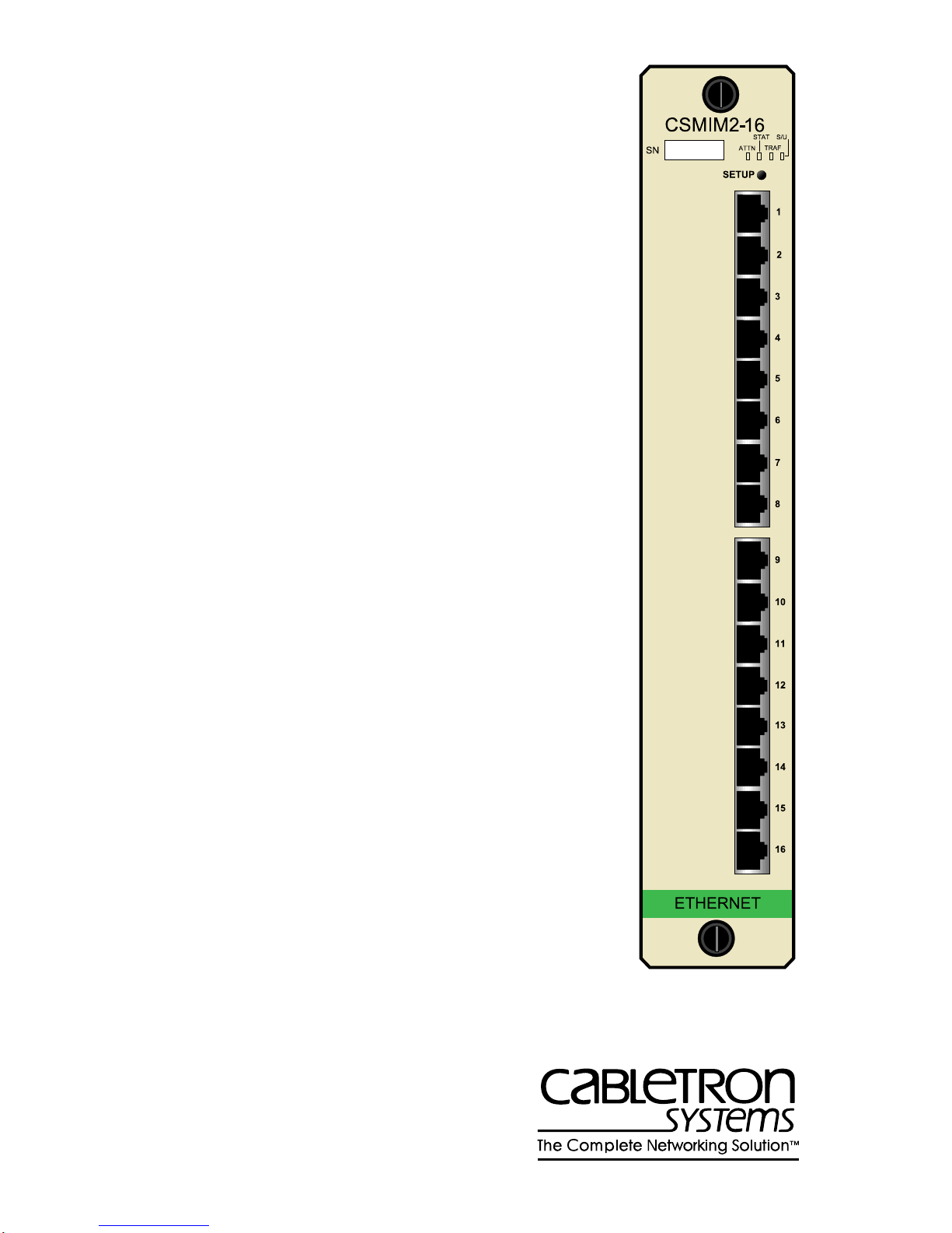
Title Page
CSMIM2 COMMUNICATIONS
SERVER MODULE
INSTALLATION GUIDE
Page 2

Page 3

NOTICE
Cabletron Systems reserves the right to make changes in specifications and other
information contained in this document without prior notice. The reader should in all cases
consult Cabletron Systems to determine whether any such changes have been made.
The hardware, firmware, or software described in this manual is subject to change without
notice.
IN NO EVENT SHALL CABLETRON SYSTEMS BE LIABLE FOR ANY
INCIDENTAL, INDIRECT, SPECIAL, OR CONSEQUENTIAL DAMAGES
WHATSOEVER (INCLUDING BUT NOT LIMITED TO LOST PROFITS) ARISING
OUT OF OR RELATED TO THIS MANUAL OR THE INFORMATION CONTAINED
IN IT, EVEN IF CABLETRON SYSTEMS HAS BEEN ADVISED OF, KNOWN, OR
SHOULD HAVE KNOWN, THE POSSIBILITY OF SUCH DAMAGES.
© Copyright April 1997 by:
Cabletron Systems, Inc.
P.O. Box 5005
Rochester, NH 03866-5005
All Rights Reserved
Printed in the United States of America
Order number: 9032221 April 1995
MicroMMAC, CSMIM2, MODMIM
Cabletron Systems, Inc.
Annex, Annex Three, Annex3,
and
Remote Annex 2000
of Xylogics, Inc.
HST
Standard Fax
Speed Leveling (ASL)
Ethernet
LAT
UNIX
XENIX
is a registered trademark of U.S. Robotics, Inc.
,
Courier V.32 terbo Fax, Total Control
are trademarks of US Robotics, Inc.
is a trademark of Xerox Corporation.
and
ULTRIX
are trademarks of Digital Equipment Corporation.
is a registered trademark of UNIX System Laboratories, Inc.
is a trademark of Microsoft Corporation.
, and
Micro-CS
Courier HST Dual
are trademarks of
are trademarks
, and
Adaptive
Page 4

FCC NOTICE
This device complies with Part 15 of the FCC rules. Operation is subject to the following
two conditions: (1) this device may not cause harmful interference, and (2) this device
must accept any interference received, including interference that may cause undesired
operation.
NOTE
digital device, pursuant to Part 15 of the FCC rules. These limits are designed to provide
reasonable protection against harmful interference when the equipment is operated in a
commercial environment. This equipment uses, generates, and can radiate radio frequency
energy and if not installed in accordance with the operator’s manual, may cause harmful
interference to radio communications. Operation of this equipment in a residential area is
likely to cause interference in which case the user will be required to correct the
interference at his own expense.
WARNING
approved by the party responsible for compliance could void the user’s authority to
operate the equipment.
This equipment complies with FCC Rules Part 68. The FCC Registration Number and
Ringer Equivalence Number (REN) are also located on the MicroMMACchassis rear
panel . You must provide this information to the telephone company if requested.
FCC Registration Number
3N9USA-21775-MM-E
: This equipment has been tested and found to comply with the limits for a Class A
: Changes or modifications made to this device which are not expressly
Ringer Equivalence Number (REN)
0.4B
Insert BookTitle ii
Page 5

SPECIAL REQUIREMENTS FOR CANADA
The Industry Canada Department’s label identifies certified equipment. This certification
means that the equipment meets certain telecommunications network protective,
operational and safety requirements. The Department does not guarantee the equipment
will operate to the user’s satisfaction.
Before installing this equipment, users should ensure that it is permissible to be connected
to the facilities of the local telecommunications company. The equipment must also be
installed using an acceptable method of connection. In some cases, the company’s inside
wiring associated with a single line individual service may be extended by means of a
certified connector assembly (telephone extension cord). The customer should be aware
that compliance with the above conditions may not prev ent de gradation of service in some
situations.
Repairs to certified equipment should be made by an authorized Canadian maintenance
facility designated by the supplier. Any repairs or alterations made by the user to this
equipment, or equipment malfunctions, may give the telecommunications company cause
to request the user to disconnect the equipment. For their own protection users should
ensure that the electrical ground connections of the power utility, telephone lines and
internal metallic water pipe system, if present, are connected together. This precaution
may be particularly important in rural areas.
CAUTION
contact the appropriate electric inspection authority or electrician.
: Users should not make installation connections themselves, but should
Load Number
The Load Number (LN) assigned to each terminal device denotes the percentage of the
total load to be connected to a telephone loop which is used by the device, to prevent
overloading. The termination on a loop can consist of any combination of devices subject
only to the requirement that the total of the LNs of all the devices does not exceed 100.
Industry Canada Certification Number
2179 6467A
LN =
4
Insert BookTitle iii
Page 6

Chapter x chaptitle
IC NOTICE
This digital apparatus does not exceed the Class A limits for radio noise emissions from
digital apparatus set out in the Radio Interference Regulations of the Industry Canada.
Le présent appareil numérique n’émet pas de bruits radioélectriques dépassant les limites
applicables aux appareils numériques de la class A prescrites dans le Règlement sur le
brouillage radioélectrique édicté par le ministère des Communications du Canada.
EXCLUSION OF WARRANTY
AND DISCLAIMER OF LIABILITY
1. EXCLUSION OF
Cabletron in writing, Cabletron makes no warranty , e xpressed or implied, concerning
the Program (including Its documentation and media).
CABLETRON DISCLAIMS ALL WARRANTIES, OTHER THAN THOSE
SUPPLIED TO YOU BY CABLETRON IN WRITING, EITHER EXPRESS OR
IMPLIED, INCLUDING BUT NOT LIMITED TO IMPLIED WARRANTIES OF
MERCHANTABLITY AND FITNESS FOR A PARTICULAR PURPOSE, WITH
RESPECT TO THE PROGRAM, THE ACCOMPANYING WRITTEN
MA TERIALS, AND ANY A CCOMPANYING HARDWARE.
2. NO LIABILITY FOR CONSEQ
CABLETRON OR ITS SUPPLIERS BE LIABLE FOR ANY DAMAGES
WHATSOEVER (INCLUDING, WITHOUT LIMITATION, DAMAGES FOR
LOSS OF BUSINESS, PROFITS, BUSINESS INTERRUPTION, LOSS OF
BUSINESS INFORMATION, SPECIAL, INCIDENTAL, CONSEQUENTIAL, OR
RELIANCE DAMAGES, OR OTHER LOSS) ARISING OUT OF THE USE OR
INABILITY TO USE THIS CABLETRON PRODUCT, EVEN IF CABLETRON
HAS BEEN ADVISED OF THE POSSIBILITY OF SUCH DAMAGES. BECAUSE
SOME STATES DO NOT ALLOW THE EXCLUSION OR LIMITATION OF
LIABILITY FOR CONSEQUENTIAL OR INCIDENTAL DAMAGES, OR ON
THE DURATION OR LIMITATION OF IMPLIED WARRANTEES IN SOME
INSTANCES THE ABOVE LIMITATIONS AND EXCLUSIONS MAY NOT
APPLY TO Y OU.
WARRANTY. Except as may be specifically provided by
UENTIAL DAMAGES. IN NO EVENT SHALL
iv Insert BookTitle
Page 7

SPECIAL INSTALLATION INSTRUCTIONS
MODEM ONLY
CAUTION
CERTIFIED/UL LISTED EQUIPMENT BY QUALIFIED SERVICE PERSONNEL.
CHECK THE EQUIPMENT OPERATING/INSTALLATION INSTRUCTIONS
AND/OR EQUIPMENT MANUFACTURER TO VERIFY/CONFIRM YOUR
EQUIPMENT IS SUITABLE FOR INSTALLED APPLICATION CARDS.
CAUTION
TELEPHONE PLUG/JACK) FROM THE TELEPHONE SYSTEM WHEN
INSTALLING UPGRADE OPTIONS OR WHEN THE COVERS ARE REMOVED
FROM THE HOST PRODUCT.
CAUTION
OUTSIDE OR THE INSIDE OF THE EQUIPMENT ENCLOSURE ADJACENT TO
THE MODEM CARD.
: THIS MODEM CARD IS INTENDED TO BE INSTALLED IN CSA
: ALWAYS DISCONNECT MODEM BOARD (THE ONE WITH THE
: APPLY THE ENCLOSED ADHESIVE WARNING LABEL TO THE
Insert BookTitle v
Page 8

Chapter x chaptitle
vi Insert BookTitle
Page 9

CONTENTS
CHAPTER 1 INTRODUCTION
1.1 General........................................................................................1-1
1.2 Organization of this Document....................................................1-1
1.3 Document Conventions...............................................................1-2
1.4 Getting Help.................................................................................1-2
1.5 CSMIM2 Overview.......................................................................1-3
1.5.1 Remote Network Access ................................................1-3
1.5.2 Dial-Up Routing ..............................................................1-3
1.5.3 Terminal and Communications Access ..........................1-4
1.5.4 Backplane Connectivity and Mangement .......................1-4
1.5.5 System Description......................................................... 1-4
1.5.6 CSMIM2 Front Panel ......................................................1-5
1.5.7 SETUP Switch ................................................................1-6
1.5.8 Port Activity Indicators ....................................................1-7
1.5.9 Console Port...................................................................1-7
1.5.10 Network Connection .......................................................1-7
1.5.11 Modem Connections....................................................... 1-7
1.6 CSMIM2 Physical Characteristics ...............................................1-8
1.7 Environmental requirements........................................................1-8
1.8 Approvals.....................................................................................1-8
1.9 CSMIM2 Front Panel...................................................................1-9
1.9.1 Set Up Switch .................................................................1-9
1.9.2 Port Activity Indicators ....................................................1-9
1.9.3 Console Port...................................................................1-9
1.10 MODMIM Front Panel..................................................................1-9
1.10.1 Reset Switch................................................................. 1-10
CHAPTER 2 INSTALLING THE CSMIM2
2.1 General........................................................................................2-1
2.2 Unpacking the CSMIM2...............................................................2-1
CSMIM2 Installation Guide i
Page 10

Contents
2.3 Pre-Installation.............................................................................2-2
2.3.1 Locating the Ethernet Jumpers .......................................2-2
2.3.2 Setting the Ethernet Jumpers..........................................2-3
2.3.3 Setting the Unmanaged Module Jumper.........................2-4
2.4 Installing the CSMIM....................................................................2-5
2.5 Console Port Terminal .................................................................2-7
2.6 Serial Devices..............................................................................2-7
2.7 Power-up and Test.......................................................................2-8
2.8 Auto-initializing the ROMs..........................................................2-10
2.9 Software Installation Procedures ...............................................2-12
CHAPTER 3 ROM MONITOR COMMANDS
3.1 General ........................................................................................3-1
3.2 Commands...................................................................................3-3
3.2.1 addr.................................................................................3-3
3.2.2 boot .................................................................................3-6
3.2.3 config.............................................................................3-11
3.2.4 console-baud.................................................................3-11
3.2.5 erase .............................................................................3-13
3.2.6 help................................................................................3-14
3.2.7 image.............................................................................3-14
3.2.8 ipx..................................................................................3-15
3.2.9 lat_key...........................................................................3-16
3.2.10 mop ...............................................................................3-17
3.2.11 net .................................................................................3-17
3.2.12 option_key.....................................................................3-18
3.2.13 ping................................................................................3-18
3.2.14 ports ..............................................................................3-19
3.2.15 sequence.......................................................................3-21
3.2.16 slip.................................................................................3-23
3.2.17 stats...............................................................................3-25
CHAPTER 4 TROUBLESHOOTING PROCEDURES
4.1 General ........................................................................................4-1
4.2 Power-up and Boot Procedures...................................................4-1
ii CSMIM2 Installation Guide
Page 11

Contents
4.2.1 Normal Mode ..................................................................4-2
4.2.1.1 Normal Mode Error-free Sequence................4-2
4.2.1.2 Activity N1: Testing Indicators........................4-2
4.2.1.3 Activity N2: Testing the Hardware..................4-2
4.2.1.4 Normal Mode Error States..............................4-3
4.2.1.5 Activity NE2: Hardware Failure ......................4-3
4.2.1.6 Activity NE5: Booted Wrong Image................4-3
4.2.2 Set Up Mode................................................................... 4-4
4.2.2.1 Set Up Mode Error-free Sequence.................4-4
4.2.2.2 Activity T1: Testing Indicators ........................4-4
4.2.2.3 Activity T2: Testing the Hardware ..................4-4
4.2.2.4 Activity T3: At the Monitor Prompt..................4-5
4.2.2.5 Set Up Mode Error States..............................4-5
4.2.2.6 Activity TE2: Hardware Failure.......................4-5
4.2.2.7 Activity TE7: Booted Wrong Image ................4-5
4.3 Boot Failures ...............................................................................4-6
4.3.1 Boot Error Report............................................................ 4-7
4.3.2 Correcting CSMIM2 Parameters..................................... 4-9
4.3.3 Load Server Host Not Responding...............................4-10
4.3.4 UNIX Host on the LAN.................................................. 4-10
4.3.5 UNIX Host on a SLIP Interface.....................................4-11
4.3.6 Another CSMIM2 ..........................................................4-12
4.3.7 CSMIM2 Dumps ...........................................................4-12
4.4 MODMIM Troubleshooting ........................................................4-14
APPENDIX A PORT PIN/SIGNAL ALLOCATIONS
A.1 General........................................................................................A-1
A.2 Console Port................................................................................A-1
A.3 Serial Port....................................................................................A-2
APPENDIX B CONNECTORS
B.1 General........................................................................................B-1
B.2 Additional Cabletron Cables and Connectors..............................B-2
APPENDIX C CSMIM2-16UG/MOD4-UG
PORT UPGRADE INSTRUCTIONS
C.1 General........................................................................................C-1
CSMIM2 Installation Guide iii
Page 12

Contents
C.2 CSMIM2-16UG Upgrade Kit .......................................................C-1
C.2.1 Contents of the Kit..........................................................C-2
C.2.2 Required Tools ...............................................................C-2
C.2.3 Disassembly Instructions................................................C-2
C.2.4 Installation Procedure.....................................................C-3
C.2.5 Power–up and Test.........................................................C-5
C.3 MOD4-UG Upgrade Kit...............................................................C-6
C.3.1 Contents of the MOD4-UG Kit........................................C-6
C.3.2 Required Tools ...............................................................C-7
C.3.3 CSMIM2-16 Disassembly Instructions............................C-7
C.3.4 Installation Procedure.....................................................C-7
C.3.5 MODMIM Power–up and Test......................................C-10
C.3.6 MODEXT-4 Disassembly Instructions ..........................C-11
C.3.7 Installation Procedure...................................................C-11
C.3.8 MODEXT-8 Power–up and Test...................................C-13
APPENDIX D MODEXT-4/MODEXT-8
MODEM UPGRADE INSTRUCTIONS
D.1 General .......................................................................................D-1
D.2 Contents of the Kit ......................................................................D-1
D.3 Required Tools............................................................................D-1
D.4 Installation Procedure .................................................................D-2
D.5 MODMIM Power–up and Test ....................................................D-2
iv CSMIM2 Installation Guide
Page 13

CHAPTER 1
INTRODUCTION
1.1 GENERAL
Welcome to the Cabletron Systems CSMIM2 Installation Guide. Read
through this manual to gain an understanding of the features and
capabilities of the CSMIM2. A general knowledge of Ethernet and IEEE
802.3 type data communications networks and their physical layer
components will be helpful when installing the CSMIM2.
1.2 ORGANIZATION OF THIS DOCUMENT
Chapter 1,
describes CSMIM2 features, installation requirements, network
guidelines, getting help, and operating specifications.
Chapter 2, CSMIM2
connections, attaching to the ports, power up and test information,
initializing the ROM, and preparing to load software.
Chapter 3,
commands and describes them in detail.
Chapter 4,
LANVIEW LED’s to troubleshoot problems.
Appendix A
Appendix B
Appendix C
Introduction
ROM Monitor Commands
T r oubleshooting Procedures
provides port pinout information.
lists cabling and connector specifications.
provides optional Flash Upgrade instructions.
, outlines the contents of this manual, and
Installation
, contains instructions for network
, explains accessing the ROM
, describes how to use the
CSMIM2 Installation Guide 1-1
Page 14

Chapter 1:
Introduction
1.3 DOCUMENT CONVENTIONS
The following conventions are used throughout this document:
Note
symbol. Calls the reader’s attention to any item of
NOTE
information that may be of special importance.
!
CAUTION
Caution
damage to the equipment.
Electrical Hazard Warning
that could result in personal injury or death due to an electrical
hazard.
symbol. Contains information essential to avoid
symbol. Warns against an action
1.4 GETTING HELP
f you need additional support related to this device, or if you have any
questions, comments, or suggestions concerning this manual, contact
Cabletron Systems Technical Support:
Phone (603) 332-9400
A.M
Monday – Friday; 8
CompuServe GO CTRON from any ! prompt
Internet mail [email protected]
FTP ctron.com (134.141.197.25)
Login
Password
anonymous
your email address
BBS (603) 335-3358
Modem setting 8N1: 8 data bits, 1 stop bit, No parity
For additional information about Cabletron Systems products, visit our
World Wide Web site: http://www .cabletron.com/
. – 8 P.M. Eastern Time
1-2 CSMIM2 Installation Guide
Page 15

CSMIM2 Overview
Before calling Cabletron Systems Technical Support, have the following
information ready:
•
A description of the failure
•
A description of any action(s) already taken to resolve the problem
(e.g., changing mode switches, rebooting the unit, etc.)
•
A description of your network environment (layout, cable type, etc.)
•
Network load and frame size at the time of trouble (if known)
•
The serial and revision numbers of all Cabletron Systems products in
the network
•
The device history (i.e., have you returned the device before, is this a
recurring problem, etc.)
•
Any previous Return Material Authorization (RMA) numbers
1.5 CSMIM2 OVERVIEW
The Cabletron Communications Server (CSMIM2) is a Xylogics Remote
Annex 4000™ compatible, multi-port communications server designed to
reside in the MMAC series of Cabletron hubs. The CSMIM2 integrates a
communication server with remote dial-in capabilities into the hub and
allows terminals and serial devices to be connected directly to Ethernet
LANs. It also provides network access for remote or mobile computer
users.
1.5.1 Remote Network Access
The CSMIM2 provides network support for: TCP/IP, Novell Netware, and
AppleT alk.
1.5.2 Dial-Up Routing
The CSMIM2 provides dial-up routing support for UNIX and Novell
networks. Using a CSMIM2, Network Administrators can connect two or
more networks over a standard telephone line.
CSMIM2 Installation Guide 1-3
Page 16

Chapter 1:
Introduction
1.5.3 Terminal and Communications Access
The CSMIM2 provides terminal and communications access to users on a
local area network. The CSMIM2 can connect up to 7 asynchronous serial
devices to host computers on a LAN.
1.5.4 Backplane Connectivity and Mangement
The CSMIM2, through the use of Repeater Interface Controller (RIC)
technology is capable of operating on any one of the three separate
segments (Ethernet channels A, B or C) located on the Multi Media
Access Center (MMAC) backplane. Channels are initially
user-configured using jumpers but may be changed using software
commands via local management with the EMME or EMM-E6 Ethernet
Management Modules.
1.5.5 System Description
The CSMIM2 is a powerful 32-bit device that comes with an Intel 80486
SXLC2 clock-doubled processor. The CSMIM2 read-only memory
(ROM) contains firmw are for performing power-up self-tests and loading
operational code. A non-volatile EEPROM stores the configuration
parameters.
The ROM Monitor is an interacti ve command interpreter that accesses the
ROM’s functions. ROM Monitor commands are issued through a terminal
.
connected to the console port on the CSMIM2
commands, you can:
•
Modify and display a set of EEPROM parameters.
•
Execute interactive diagnostic tests.
•
Receive information and statistics for the hardw are configuration and
the network.
•
Boot the CSMIM2 manually.
Using the ROM Monitor
The CSMIM2 is a diskless device. It obtains operational code either over
the network from a host running Micro Annex Communication Software
Version 9.2.6 or above, another CSMIM2 configured as a load server, or
from self-contained Flash Memory.
1-4 CSMIM2 Installation Guide
Page 17
CSMIM2 Overview
The CSMIM2 has a watchdog timer that is reset by the software at regular
intervals. The watchdog timer reboots the CSMIM2 in the unlikely event
of an internal software error. This feature allows the CSMIM2 to run for
long periods of time without intervention.
A modem upgrade for the CSMIM2 is available for added functionality. It
consists of a single daughter card, and can be user installed. The upgrade
kit can be purchased separately from Cabletron as part number
CSM-V.34-UGK.
LED indicators provide the user feedback on system activity. Each port
connector has an associated LED to indicate activity on the receive data
line. Several other LEDs indicate Netw ork Acti vity, diagnostic failure and
other fault connections.
1.5.6 CSMIM2 Front Panel
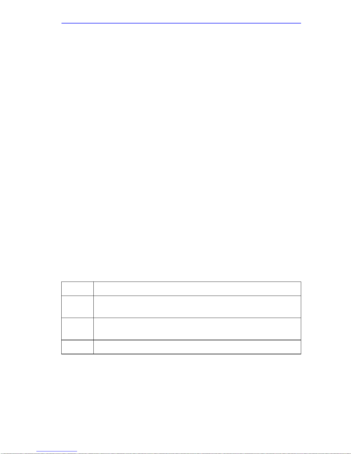
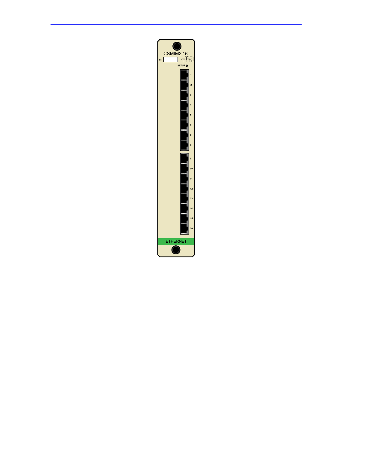
The CSMIM2 (Figure 1-1) front panel contains the following:
•
4 system indicators
•
3 Ethernet segment indicators
•
16 or 32 port LEDs
•
a setup switch (also Reset)
Table 1-1 Front Panel System Indicators
STAT
ATTN
TRAF
S/U On
On after the unit successfully passes its self-test.
On when the unit requires operator attention; on for a short period of
time during Boot; flashing when the unit encounters a problem.
Flashing when the unit successfully transmits data to, and receives
data from, the network.
only
when the board is in Setup mode.
CSMIM2 Installation Guide 1-5
Page 18
Chapter 1:
Introduction
Figure 1-1 CSMIM2-16 front panel
1.5.7 SETUP Switch
The
SETUP
CSMIM2 from Normal to Test. It also functions as a
Note below). The CSMIM2 automatically powers up in normal mode. To
enter test mode, press the SETUP button within three seconds of
powering-up.
Additionally, a Setup signal is provided from the MicroMMAC
motherboard. When this signal is acti ve, it will perform a cold start of the
CSMIM2.
button allows you to change the operational mode of the
Reset
button (see
1-6 CSMIM2 Installation Guide
Page 19

CSMIM2 Overview
1.5.8 Port Activity Indicators
The LED activity indicators associated with ports 1-7 blink to indicate
data either data transmitted to or received by that port. The “M” port
lights to indicate the modem is seeing activity. The 5 modem LED’s blink
to indicate the modem is sending or receiving data from the WAN
network.
1.5.9 Console Port
The CSMIM2 uses port 1 as a console port during SETUP. To access the
console port, press the Setup switch within 5 seconds of powering-up.
The console port provides access to the ROM Monitor commands when
the CSMIM2 is in set up mode. After returning to normal mode, Port 1
functions as a serial port. Refer to Appendix B for console pinout
information.
1.5.10 Network Connection
The CSMIM2 connects to Ethernet networks through its backplane
connection to the MMAC chassis.
1.5.11 Modem Connections
The CSMIM2 supports the addition of Cabletron Systems Modem
Extention Modules, such as the MODMIM and MODEXT series.
CSMIM2 Installation Guide 1-7
Page 20

Chapter 1: Introduction
1.6 CSMIM2 PHYSICAL CHARACTERISTICS
Dimensions:
Height: 10 in (25.4 cm)
Width: 2 in (5 cm)
Depth: 13.4 in (34 cm)
Weight:
CSMIM2-16: 1 lb 11 oz (0.7 kg)
CSMIM2-32: 2 lb 4 oz (1.03 kg)
Power:
CSMIM2-16: 5.8A @ 5V
CSMIM2-32: 6.3A @ 5V
1.7 ENVIRONMENTAL REQUIREMENTS
Operating:
5° to 40°C (41° to 104° F)
10% to 90% relative humidity, noncondensing
Non-operating:
-40° to 73°C (-22° to 164° F)
5% to 95% relative humidity, noncondensing
1.8 APPROVALS
Approvals
Safety:
This equipment meets the safety requirements of
UL 1950, CSA C22.2 No. 950, EN60950, IEC 950,
and 73/23/EEC.
Electromagnetic Compatability:
This equipment meets the requirements of FCC Part
15, EN 55022, VCCI V-3/93.01, CSA C108.8, EN
50082-1, and 89/336/EEC.
Telecom:
1-8 CSMIM2 Installation Guide
FCC Part 68, Industry Canada CS-02/CS-03
Page 21

CSMIM2 Front Panel
1.9 CSMIM2 FRONT PANEL
1.9.1 Set Up Switch
The Set Up switch allows you to change the operational mode of the
CSMIM2 from normal to set up. The CSMIM2 automatically powers up
in normal mode. To enter set up mode, press the Set Up switch within 3
seconds of powering-up. When the S/U indicator lights, the CSMIM2 is
in set up mode.
The Set Up switch provides a dual function. Depressing the Set Up switch
for approximately 3 seconds causes the CSMIM2 to enter a reset state
identified by all port activity indicator LEDs ON, which is the same state
entered after power is turned on.
1.9.2 Port Activity Indicators
These indicators display serial port activity during normal operations.
1.9.3 Console Port
The CSMIM2 uses port 1 as a console port. To access the console port,
press the Set Up switch within 30 seconds of powering-up. The console
port provides access to the ROM Monitor commands when the CSMIM2
is in set up mode. Refer to Appendices A and B for console pinout
information.
1.10 MODMIM FRONT PANEL
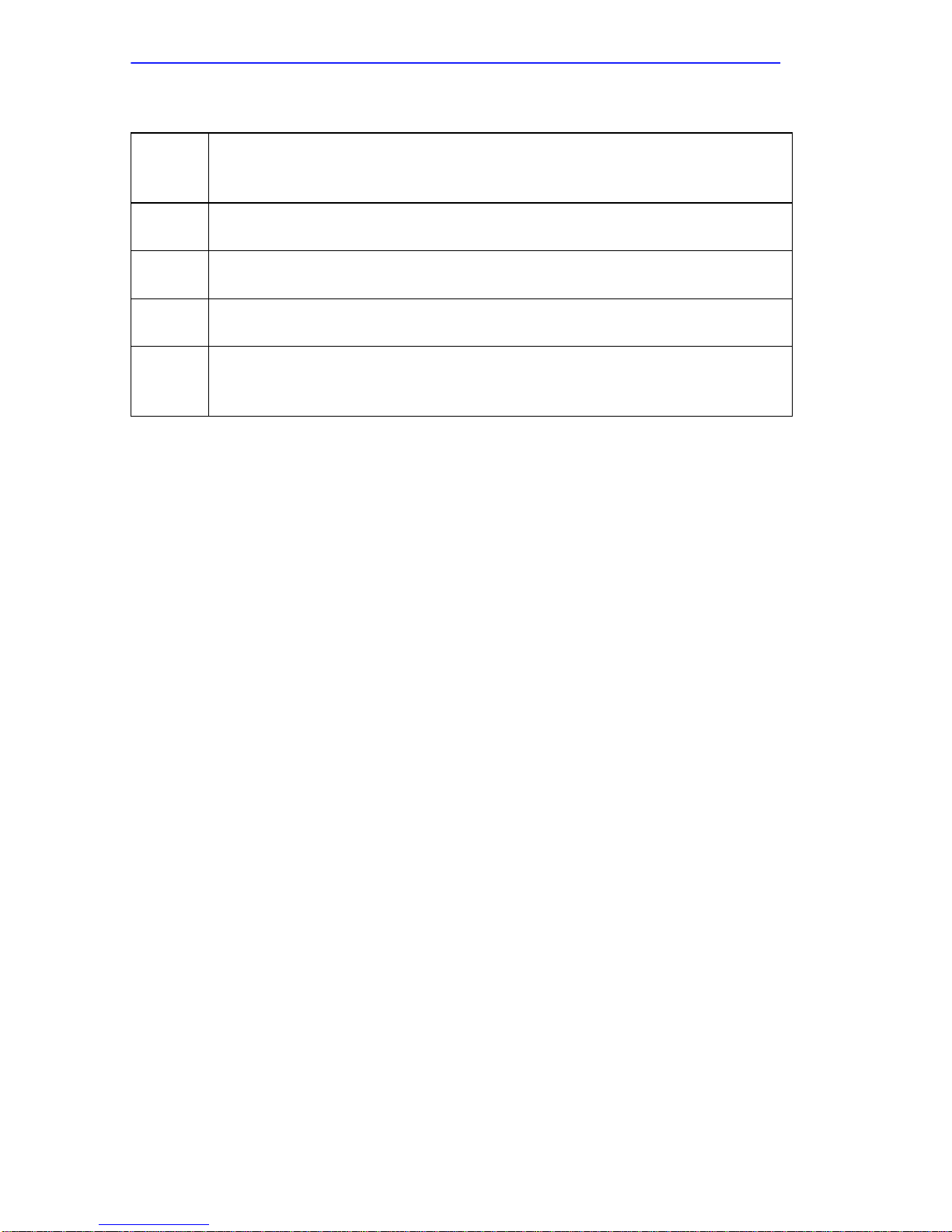
The MODMIM uses the same LEDs as the CSMIM2-16 but adds an
additional five green LEDs and a reset switch for each modem port (refer
to Figure 1-2):
• 5 green LED status indicators
• a reset switch
CSMIM2 Installation Guide 1-9
Page 22
Chapter 1: Introduction
Table 1-2 MODMIM Port Status Indicators
CTS
DTR
TXD
RXD
DCD
Clear to Send
hardware flow control is enabled (&H1, &H3). Always on during
synchronous connections.
Data Terminal Ready
from the computer or terminal.
Send Data.
the MODMIM.
Received Data
passes received data bits to the computer or terminal.
Carrier Detect
(carrier) from a remote modem, indicating that data transmission is
possible.
. ON until the modem lowers CTS when Transmission Data
. ON when the MODMIM receives a DTR signal
Flashes when the computer or terminal sends a data bit to
. Flashes when the MODMIM sends result codes or
. On when the MODMIM receives a valid data signal
1.10.1 Reset Switch
The Reset switch is accessible through the front panel and allows you to
manually reset each individual modem port.
1-10 CSMIM2 Installation Guide
Page 23

CHAPTER 2
INSTALLING THE CSMIM2
2.1 GENERAL
This chapter details the installation and set up procedures for the
CSMIM2 family . Unless otherwise specified, the term CSMIM2 is used to
signify all members of the CSMIM2 family including the MODMIM-4
with its various upgrade options. See appendices for installation
procedures for DVRAM, Flash, and board upgrades.
2.2 UNPACKING THE CSMIM2
Unpack the CSMIM2 as follows:
Observe all antistatic precautions when handling sensitive
!
CAUTION
electronic equipment.
1. Remove the shipping material covering the CSMIM2.
2. Carefully remove the module from the shipping box. Leave the
module in its non-conductive bag until you are ready to install it.
3. Visually inspect the non-conductive bag. If there are any signs of
damage, contact Cabletron Systems Technical Support immediately.
4. Place the static grounding strap properly on your wrist before opening
the non-conductive bag.
5. Open the non-conductive bag by tearing the black and yellow tape
seal.
Do not cut the bag open, as damage to the CSMIM2 may
!
CAUTION
6. Perform a second visual inspection of the module.
result.
CSMIM2 Installation Guide 2-1
Page 24

Chapter 2: Installing the CSMIM2
2.3 PRE-INSTALLATION
Installing the CSMIM2 involves setting jumpers to select an Ethernet
channel and management services for the module.
2.3.1 Locating the Ethernet Jumpers
The CSMIM2/MODMIM has two Ethernet jumpers and one Unmanaged
Module Group jumper. Figure 2-1 shows the locations and jumper
numbers for the Ethernet and Unmanaged Module jumpers.
2-2 CSMIM2 Installation Guide
Page 25

Unmanaged Module Jumper
Pre-Installation
Ethernet Jumpers J11, J12
FUSE
1
2
3
ETHERNET JUMPER SETTINGS
1 2 3
J12 J11
Jumper Settings for
operating on Ethernet A
UNMANAGED MODULE JUMPER SETTINGS
1
2
3
J15
1 2 3
J15
1 2 3
DISABLED
(Normal Setting)
J12
1 2 3
J11
1 2 3
Jumper Settings for
operating on Ethernet B
(factory setting)
1 2 3 1 2 3
J12 J11
ENABLED
1
(Channels B or C only)
2
3
J15
1 2 3
J12 J11
Jumper Settings for
operating on Ethernet C
2.3.2 Setting the Ethernet Jumpers
The Ethernet jumpers determine how your CSMIM2 operates on the
network. You can set the jumpers so that the CSMIM2 operates on
channels A, B, or C. Refer to Figure 2-1 and configure the jumpers as
follows.
CSMIM2 Installation Guide 2-3
Figure 2-1 CSMIM2 Jumper Settings
Page 26

Chapter 2: Installing the CSMIM2
• To operate on Channel A: Place the J11 jumper over the center pin
and pin 3, and the J12 jumper over the center pin and pin 3.
• To operate on Channel B: Place the J11 jumper over the center pin
and pin 1, and the J12 jumper over the center pin and pin 3.
• To operate on Channel C: Place the J11 jumper over the center pin
and pin 3, and the J12 jumper over the center pin and pin 1.
2.3.3 Setting the Unmanaged Module Jumper
CSMIM2s allow grouping of the B and C channels into unmanaged
modules to provide two additional Ethernet networks. All MIMs in the
MMAC to the left of the CSMIM2 become part of the unmanaged module
group. These additional networks cannot be seen or controlled from the
EMME or EMM-E6 installed in the MMAC.
Unmanaged Module Group jumper settings can be overridden
NOTE
by an EMME or EMM-E6 installed in the MMAC.
To set the unmanaged module group jumper, refer to Figure 2-1 and
configure the jumper as follows:
• To operate normally (maintain the continuity of the backplane):
Place the J15 jumper over the center pin and pin 3.
• To operate in Unmanaged Module Group mode: Place the J15
jumper over the center pin and pin 1.
2-4 CSMIM2 Installation Guide
Page 27
Installing the CSMIM
2.4 INSTALLING THE CSMIM
Installing the CSMIM2 into any MMAC hub is an easy operation and
requires no special tools. Howe ver , when you install your de vice, keep the
following in mind:
Any installation operations should be performed only by
qualified personnel.
You may install the CSMIM2 in any slot except for slot 1
!
CAUTION
!
CAUTION
(farthest slot to the right) of the MMAC chassis.
Observe all antistatic precautions when handling sensitive
electronic equipment.
Install the CSMIM2 into the MMAC-FNB (backplane) as follows:
We recommend powering down your MMAC when inserting or
NOTE
removing modules, even though Cabletron Systems modules
have “hot swap” capabilities.
1. Remove the safety bars that protect the chassis and remove any
module to be replaced or blank MMAC slot covers, in accordance with
the installation and removal procedures for these items.
2. Holding the CSMIM2 by the front panel, or by the edges of the board,
align the bottom and top edges of the board with the guides. Make sure
that both the bottom and top edges of the card rest in these guides.
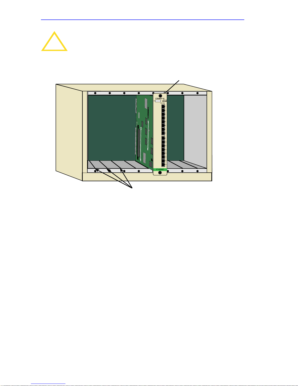
3. Slide the CSMIM2 (Figure 2-2) into the desired slot of the MMAC
card cage.
4. Firmly press the module connections into the backplane. Do not try to
force the module into place or use the knurled knobs to draw the
module into the backplane.
CSMIM2 Installation Guide 2-5
Page 28
Chapter 2: Installing the CSMIM2
Forcing a misaligned module into place can damage the
!
CAUTION
CSMIM2 or the MMAC backplane.
MMAC-M8FNB
Figure 2-2 Installing the CSMIM2
Knurled Knob
07
Module Guide Channels
5. Secure the module to the MMAC chassis by tightening the knurled
knobs. If you do not tighten the knurled knobs, vibration can cause the
module to lose contact with the backplane and disrupt your network.
6. Reinstall the MMAC chassis safety bars.
7. Power-up the MMAC (if it is not already ON).
8. After the system boot procedure, the CPU LED should be indicating
proper CSMIM2 operation.
Proceed to connect the appropriate network segments to the CSMIM2.
2-6 CSMIM2 Installation Guide
Page 29

Console Port Terminal
2.5 CONSOLE PORT TERMINAL
Connect a terminal to port 1. You need this terminal to access the ROM
Monitor and boot the CSMIM2 for the first time. Set the terminal to 9600
baud, eight data bits, no parity, one stop bit, and XON/XOFF flow
control. The ROM Monitor assumes that this terminal is CRT-based and
displays the backspace (BS) character accordingly.
Press Set Up within 3 seconds of powering up, to put the CSMIM2 into
ROM Monitor mode. You can also reset and set up the CSMIM2 by
pressing Set Up until all port activity LEDs are ON, then press Set Up
again within 3 seconds to put the server into ROM Monitor mode.
The red ATTN light is ON when the unit is in ROM Monitor
NOTE
state.
2.6 SERIAL DEVICES
The CSMIM2 provides 16 or 32 connections, depending on the port
configuration. The MODMIM provides 16 serial ports as well as 4 to 12
V.32 bis terbo modems.
The CSMIM2/MODMIM serial cables conform to both the RS232 and
RS423 specifications regarding the data signals (TxD, RxD). However, it
is possible to exceed the specifications’ cable limits given high quality
cables that are run in an electrically quiet environment. Cabletron only
guarantees operation with cables that conform to the appropriate
specification. Table 2-1 lists the maximum recommended cable lengths.
The CSMIM2 can incur damage if the cables conduct transients
!
CAUTION
such as those induced by lightning strikes, etc.
Table 2-1 Maximum Recommended Cable Lengths
Line Speed Cable Length: Feet Meters
50 to 19.2kbps 250 75
38.4kbps 200 60
57.6kbps 100 30
115.2kbps 50 15
CSMIM2 Installation Guide 2-7
Page 30

Chapter 2: Installing the CSMIM2
If you exceed these recommended cable lengths, you must
NOTE
compensate for any resulting problems by reducing the baud
rate, using low capacitance cable, etc. Exceed these distances
at your own risk.
2.7 POWER-UP AND TEST
1. Apply power (insert into MMAC).
The CSMIM2 now runs its ROM-resident power-up diagnostics. The
indicators momentarily light and then turn off, except for the Ethernet
Segment indicator (by default B).
2. Set the CSMIM2 into Set Up mode (S/U LED on).
Press the Set Up switch on the front panel. The S/U indicator lights
when the unit enters Set Up mode.
You must press the Set Up switch within 3 seconds of either
NOTE
powering-up or Reset to enter Set Up mode.
Next, the CSMIM2 runs diagnostic tests causing the Traf indicator to
flash. If the diagnostics complete successfully, the Stat and Attn
indicators light, and the ROM Monitor prompt (
monitor::) appears on
the terminal. The tests complete in approximately one minute. If the
prompt appears, go to Step 3.
If the Stat and Attn indicators do not light within one minute or if the
indicators flash, a hardware failure has occurred. Contact Cabletron
technical support.
2-8 CSMIM2 Installation Guide
Page 31

Power-up and Test
3. Verify the CSMIM2/MODMIM hardware configuration.
At the monitor prompt on the console, type config and press the
Return key. The following is a typical
MODMIM-4 configuration display:
monitor:: config
Revision/Configuration Information
ROM Software Rev #0800
Board ID 42 Ethernet Address 00-80-2D-00-B8-3C
Memory Size:2 Meg
Flash Size: N/A Flash ID: N/A
EEPROM Size: 65504
Total Number of Ports: 20
ASYNC Config
Number of Ports: 16
Max Port Speed: 115.2 Kbps
MODEM Config
Number of Ports: 4
Port # 17 18 19 20
ID 1445 1445 1445 1445
Status OK OK OK OK
To record the CSMIM2’s Ethernet address for future reference: at the
monitor prompt, type addr -d and press the Return key. The display
looks like this:
monitor:: addr -d
Ethernet address (hex): 00-80-2D-00-B8-3C
Internet address: <invalid or uninitialized>
Subnet mask: <invalid or uninitialized>
Preferred load host address: <any host>
Broadcast address: 0.0.0.0
Preferred dump address: 0.0.0.0
Type of IP packet encapsulation: <ethernet>
Load broadcast: N
You are prompted for the gateway address only if the internet
NOTE
address differs from the preferred load host address based on
the subnet mask. If these addresses are the same, the
CSMIM2 assumes there is no gateway.
CSMIM2 Installation Guide 2-9
Page 32

Chapter 2: Installing the CSMIM2
2.8 AUTO-INITIALIZING THE ROMS
The CSMIM2 supports the BOOTP and RARP protocols. The ROMs use
these protocols to obtain boot information without requiring any manual
set-up on the CSMIM2.
• BOOTP is a bootstrap protocol that allows a diskless client to
determine its Internet address, the Internet address of the server, and
the name of the file to be loaded into memory.
•RARP (Reverse Address Resolution Protocol) maps a hardware
•
address into an Internet address.
The ROMs invoke this system of acquiring boot information when a boot
is initiated and the CSMIM2’s Internet Address is not initialized. Under
this condition, the CSMIM2 first tries to get boot information via
BOOTP; if BOOTP fails, it tries to get boot information via RARP. If
neither protocol is successful, the CSMIM2 either prompts the user for
the Internet address (if in Set Up mode) or it lights the Attn LED to
indicate the Internet address is not set (if in Normal mode).
For a successful BOO TP retrie v al, a bootpd must be running on a host on
the same network as the CSMIM2 and must have the appropriate
information in the bootptab file. The CSMIM2’s BOOTP
implementation adheres to rfc951, rfc1048, and rfc1084. Below is a
sample bootptab file entry used to initialize the CSMIM2 named
terminator.
csmimdefault:\
:sm=255.255.255.0:gw=132.245.22.66:\
:hn:vm=auto:to=-18000:
terminator:ht=1:ha=00802d004879:ip=132.245.22.226:tc=csmimdefault:
In the previous example:
• sm is the subnet mask;
• gw is the load/ dump gateway address; ht is host type (1=Ethernet);
• ip is the CSMIM2’s Internet Address; ha is the CSMIM2’s hardware
address (Ethernet Address); and
• vm is the Vendor Magic Cookie.
2-10 CSMIM2 Installation Guide
Page 33

Auto-initializing the ROMs
When the CSMIM2 receives a BOOTP response with the sm, gw, and ip
set, it sets the respective parameters: subnet_mask,
load_dump_gateway, and inet_addr. The Vendor Magic Cookie must
be set to auto. This indicates that bootpd should respond to the client
(CSMIM2 in this case) with whatever format the client requests; the
CSMIM2 (client) always requests in the decimal dot notation format
(99.130.83.99). The bootpd adds the address of the host on which it is
running as the Server Address in the bootp response message. The ROMs
use the Server Address as the preferred load host and store it in the
pref_load_addr parameter.
The bootpd must be running on the CSMIM2’s preferred load
NOTE
host.
If the CSMIM2 does not receive a successful BOOTP response, it uses
RARP to get the boot information. For a successful RARP retrieval,
TCP/IP must be running on a host that is on the same network as the
CSMIM2 and the the host’s ARP table must be initialized with the
CSMIM2’s Internet and Ethernet addresses (see the arp man page,
arp -s).
The only boot information that RARP provides is the CSMIM2’s Internet
address. The ROMs save this information in the inet_addr parameter.
The ROMs use default information for the subnet mask and preferred
load host. This means the ROMs will broadcast their request.
The host serving the CSMIM2 its boot information must be running on
the same network as the CSMIM2 because the CSMIM2 only broadcasts
BOOTP and RARP queries.
CSMIM2 Installation Guide 2-11
Page 34

Chapter 2: Installing the CSMIM2
2.9 SOFTWARE INSTALLATION PROCEDURES
Install the operational code on a UNIX host before loading it on a
CSMIM2. The CSMIM2 Installation Notes describe how to install
software on a host. The CSMIM2 may also be booted from software
loaded on a CSMIM, another CSMIM2 or from Flash memory (see
Chapter 3). When loading the CSMIM2 software for the first time, use the
ROM Monitor commands. At the monitor prompt:
1. Execute the erase command to clear the EEPROM. (See the erase
command in Chapter 3.)
2. Execute the addr command to:
Enter the CSMIM2’s Internet address.
Modify any other parameters that the CSMIM2 may require for the
initial boot, i.e., the preferred load host’s Internet address and the
subnet mask. (See the addr command in Chapter 3.)
3. If you are booting the CSMIM2 using a Serial Line Internet Protocol
(SLIP) network interface, you must:
Use the slip command to modify the port parameters for the SLIP
network interface (see the slip command in Chapter 3).
Use the sequence command to list the SLIP network interface in the
load/dump interface list (see the sequence command in Chapter 3).
4. Execute the boot command (see the boot command in Chapter 3).
After successful execution of the boot command, your CSMIM2 is up
and running.
2-12 CSMIM2 Installation Guide
Page 35

CHAPTER 3
ROM MONITOR COMMANDS
3.1 GENERAL
This chapter describes the ROM Monitor commands. These commands
are accessed through a terminal connected to port 1 when the CSMIM2 is
in SETUP mode. Pressing the SETUP switch within 3 seconds of
powering up puts the CSMIM2 into Set Up mode.
The ROM Monitor commands allow you to set a number of EEPROM
parameters. Some of these parameters, like the unit’ s Internet address, are
required for booting the CSMIM2; some parameters, like the broadcast
address, are required if the network configuration differs from the
supplied defaults. Table 3-1 lists the ROM Monitor commands.
Other parameters, although not required, are recommended for the
CSMIM2’s initial boot. Setting these parameters rather than using the
assigned defaults minimizes errors during the initial boot. For example,
setting the parameter that defines the preferred load host enables the
CSMIM2 to load by requesting assistance from a specific host rather than
by broadcasting that request to all hosts on the Ethernet.
You can define the same parameters using the Network Administrator
(na) program as you can using the ROM Monitor. The CSMIM Network
Administrator’s Guide (p/n 9031101) describes the na program in detail.
ROM Monitor commands generally provide data about current EEPROM
parameters. When appropriate, they also display a prompt that allows the
operator to change those parameters. Default or current values for
parameters are displayed in brackets. For example:
Enter broadcast address [132.245.6.255]:
At the prompt enter a different value or press the Return key <cr> to
leave the displayed value unchanged.
You can use unique abbreviations for all R OM Monitor commands except
erase. For example, enter boot as bo, and enter net as n. If you enter an
abbreviation that is not unique enough, an error message is displayed on
the console terminal.
CSMIM2 Installation Guide 3-1
Page 36

Chapter 3: ROM Monitor Commands
Table 3-1 ROM Monitor Command
addr [-d]
boot [-v] [<file>]
boot [-l] [<file>]
config
Displays and sets EEPROM values relevant to network
addressing, including the CSMIM2’s Internet address.
Manually boots and loads the CSMIM2’s operating
code.
Erases the existing Flash memory and copies a new
image to Flash.
Displays the current hardware configuration and
revision levels.
console-baud Changes the console port’s baud rate.
erase Erases non-volatile memory.
help (or “?”) Display the list of ROM Monitor commands.
image [-d/<file>]
Displays and/or sets the load image and TFTP load
dump names.
ipx [-d] Sets IPX load/dump file server.
lat_key [-d] Sets LAT key.
mop [-d] Sets MOP load/dump address.
net
Executes an Ethernet stand-alone external loopback
test.
option_key [-d] Sets or displays the option key.
ping
ports [-d]
sequence
[-d | <list>]
Sends ICMP ECHO_REQUEST, host [data size]
[npackets].
Shows the current status of all ports and tests specified
port(s).
Displays and edits the load/dump interface list.
slip [-d] <port> Configures an SL/IP interface.
stats [-slip]
Displays current network statistics gathered by the
ROM.
3-2 CSMIM2 Installation Guide
Page 37

Commands
3.2 COMMANDS
Following is an explanation of each of the ROM monitor commands,
syntax and other usage information.
3.2.1 addr
The addr command displays and sets several CSMIM2 operating parameters
(EEPROM values) relevant to IP network addressing:
• Internet address.
• Subnet mask.
• Broadcast address.
• Preferred Load Host address.
• Preferred Dump Host address.
• Load/Dump Gateway address.
• Type of IP Packet encapsulation.
• Load Broadcast
The addr -d command also displays the unit’s ROM-resident Ethernet
address in hexadecimal notation (see the CSMIM/MicroCS
Administrator’s Guide for UNIX). The command syntax is:
addr [–d]
If you enter the addr command without the –d argument, the console
prompts you for each Internet address. Enter Internet addresses using the
standard decimal dot (.) notation.
The addr –d command displays the CSMIM2’s Ethernet address, IP
address, subnet mask, broadcast address, preferred load host address,
preferred dump host address, load/dump gateway address, IP
encapsulation type, and Load Broadcast. The addr -d command cannot
be used to make changes to any of the displayed parameters.
CSMIM2 Installation Guide 3-3
Page 38

Chapter 3: ROM Monitor Commands
The addr command display looks like this:
monitor:: addr
Enter Internet address [<uninitialized>]:: 192.9.200.214
Internet address: 192.9.200.214
Enter Subnet mask [255.255.0.0]::
Enter Broadcast address [0.0.0.0]:: 192.9.200.0
Broadcast address: 192.9.200.0
Enter Preferred Load Host address [<any host>]:: 192.9.200.88
Preferred Load Host address: 192.9.200.88
Enter Preferred Dump Host address [0.0.0.0]:: 192.9.200.88
Preferred Dump Host address: 192.9.200.88
Enter Load/Dump Gateway address [<uninitialized>]:: 192.9.200.
Load/Dump Gateway address: 192.9.200.88
Select type of IP packet encapsulation (ieee802/ethernet)
[<ethernet>]::
Load Broadcast Y/N [Y]::
The addr -d command display looks like this:
monitor:: addr -d
Ethernet address (hex): 00-80-2D-00-C6-1E
Internet address: 192.9.200.214
Subnet mask: 255.255.0.0
Broadcast address: 192.9.200.0
Preferred Load Host address: 192.9.200.88
Preferred Dump Host address: 192.9.200.88
Load/Dump Gateway address: 192.9.200.10
Type of IP packet encapsulation: <ethernet>
Load Broadcast: Y
3-4 CSMIM2 Installation Guide
Page 39

Commands
The CSMIM2 must have an Internet (IP) address in its memory before it
can load its operational image across the Ethernet via the IP protocol.
Therefore, you must enter the IP address before booting the CSMIM2
from a UNIX load host. If you do not define an IP address for the
CSMIM2, it will attempt to learn the address using BOOTP or RARP. If
you do not define a subnet mask, the CSMIM2 uses the generic mask for
the specified IP address.
The CSMIM2 tries to boot from a preferred UNIX load host. If you do not
define a preferred load host, the CSMIM2 broadcasts its load request on
the subnet and loads software from the first host that responds.
If the part of the IP address containing the network address differs from
the preferred load or dump host, that host must be reached through a
gateway. The addr command prompts you for this gateway’s IP address.
The CSMIM2 uses the broadcast address parameter when loading a file.
If this parameter contains a specific address (for example,
132.245.6.255), the CSMIM2 uses only that address for broadcast. If the
value is all zeroes (0.0.0.0), the ROM Monitor tries various combinations
of broadcast addresses and subnet or network broadcasts. The CSMIM2
broadcasts its request three times for each possible combination of
broadcast addresses.
You can specify the IP encapsulation type as either ethernet for Ethernet,
or ieee802 for IEEE 802.2/802.3. The default IP encapsulation is
ethernet. Many systems have hardware Ethernet interfaces that are IEEE
802.3 compliant, but very few actually do 802.3 IP packet encapsulation.
Do not change this parameter unless you know absolutely that
NOTE
your Ethernet does 802.2/802.3 IP packet encapsulation. An
incorrect IP encapsulation type prevents your CSMIM2 from
booting.
CSMIM2 Installation Guide 3-5
Page 40

Chapter 3: ROM Monitor Commands
3.2.2 boot
The boot command requests the loading of appropriate CSMIM2
operating software from the preferred load host. The command syntax is:
boot [–lv | filename]
The boot –l command is supported only if the self-boot option
NOTE
(Flash) is installed.
Typing the letter q or CONTROL-C interrupts the boot.
If you try to boot with a non-existent image file name, the
CSMIM2 will hang as it searches for the image. You must press
RESET button to recover.
the
A successful boot disables the Console and the ROM monitor.
The boot command accepts a file name for the CSMIM2’s image. If the
file name is not specified, boot displays the default file name and prompts
for one. If you do not provide a file name, or have not defined one for the
CSMIM2, boot requests the default file oper.56.enet. You can also enter
a file name using the image command.
The CSMIM2 boots from the defined preferred load host (UNIX/IP,
Novell/IPX, or VAX VMS/MOP). If the preferred load host is not def ined
or does not respond, the CSMIM2 broadcasts on the Ethernet and loads
from the first host that responds.
To initiate loading, the CSMIM2 sends a load request message to the
selected host. After receiving a response, the CSMIM2 loads its
operational code to RAM memory. When loading is complete, it transfers
control to the newly-loaded program. The CSMIM2 displays a symbol on
the console for each data block received during the boot.
When the CSMIM2 begins to boot, it displays the load server host’s IP
address. If the unit does not boot successfully after several attempts, it
displays a boot attempt failed message; if the unit has opened the boot file
and an error occurs during the boot process, it displays a boot error report
on the console and returns to the ROM Monitor. The boot error report can
help determine the cause of the boot failure.
3-6 CSMIM2 Installation Guide
Page 41

Commands
During a boot, the console may display four possible status symbols: “.”
indicates received data blocks, “?” indicates unanswered requests, “*”
indicates transmission errors, and “! ~XXXX~” is a status word from the
Ethernet chip on the CSMIM2 indicating a gross problem with the
Ethernet connection (if this symbol appears in your boot command
display, contact technical support).
The status word “! ~XXXX~”, where XXXX are four hexadecimal digits,
decodes as follows:
8000 = Command complete
4000 = Chip is busy
2000 = Command completed without error
1000 = Command aborted by an abort command
800 = Late collision detected
400 = Carrier lost
200 = CTS lost
100 = DMA underrun
80 = Transmission deferred because link was busy
40 = Collision detected during interframe spacing
(SQE/Heartbeat detected)
20 = Excessive collisions
10 = Reserved
The lowest nibble (bits 3 to 0) are a count of collisions during this
transmission. For example:
~8802~ = Complete, Late collision, 2 collisions
~8841~ = Complete, Late Collision, SQE detected, 1 collision
CSMIM2 Installation Guide 3-7
Page 42

Chapter 3: ROM Monitor Commands
The boot command display (using bfs) looks like this:
monitor:: boot
Enter boot file name[(ip) “oper.56.enet”,\
(mop) “OPER_56_ENET.SYS”]::
Requesting default boot file “OPER_56_ENET.SYS” for MOP/VMS\
loads and “oper.56.enet” for all other protocols.
Unanswered requests shown as ‘?’,transmission errors as ‘*’.
Requesting boot from 192.9.200.88 via Ethernet...
Booting BFS file using open delay of 8
Booting BFS file from 192.9.200.88
Header received OK. Received data blocks shown as ‘.’.
. . . . . . . . . . . . . . . . . . . . . . . . . . . . . .. .
. . . . . . . . . . . . . . . . . . . . . . . . . . . . . . . .
. .. . . . . . . . . . . ? . . . . . . . . . . . . . . . . . .
. . . . . . . . . . . . . . . . . . . . . . . . . . . . . . . .
. * . . . . . . . . . . . . . . . . . . . . . . . . . . . . * .
. . . . . . . . . . . . . . . . . . . . . . . . . . . . . . . .
. . . . . . . . . . . . . . . ? . . . . . . . . . . . . . . . .
. . . . . . . . . . EOF
The next example shows a boot using tftp. The CSMIM2 always tries to
open a file using bfs first. If unsuccessful, the CSMIM2 uses tftp to open
the file.
monitor:: boot
Enter boot file name [(ip) “oper.56.enet”, \
(mop) “OPER_56_ENET.SYS”]::
Requesting default boot file “OPER_56_ENET.SYS” for MOP/VMS\
loads and “oper.56.enet” for all other protocols.
Unanswered requests shown as ‘?’,transmission errors as ‘*’.
Requesting boot from 192.9.200.88 via Ethernet...
Booting BFS file using open delay of 8
?
Booting TFTP file using open delay of 8
Booting TFTP file from 192.9.200.88
Header received OK. Received data blocks shown as ’.’.
.. . . . . . . . . . . . . . . . . . . . . . . . . . . . . . .
. . . . .. . . . . . . . . . . ? . . . . . . . . . . . . . . .
. . . . . . . . . . . . . . . . . . . . . . . . . . . . . . . .
. . . . * . . . . . . . . . . . . . . . . . . . . . . . . . . .
. * . . . . . . . . . . . . . . . . . . . ? . . . . . . . . . .
. . . . . . . . . . . . . . . . EOF
3-8 CSMIM2 Installation Guide
Page 43

Commands
The boot –l command downloads and saves the operational image to
non-volatile memory, erases the existing Flash memory, copies the new
image from non-volatile memory to Flash memory, and then executes the
image.
The boot –l command is supported only if the self-boot option
NOTE
is installed.
After executing a boot –l, the ls command may not show the
newly-loaded image.
The boot –l command display looks like this:
monitor:: boot –l
Enter boot file name [(ip) “oper.56.enet”, \
(mop) “OPER_56_ENET.SYS”]::
Requesting default boot file “OPER_56_ENET.SYS” for \
MOP/VMS loads and “oper.56.enet” for all other protocols.\
Unanswered requests shown as ‘?’, transmission errors as\ ‘*’.
Requesting boot from 192.9.200.88 via Ethernet...
Booting BFS file using open delay of 8
Booting from 192.9.200.88
Header received OK. Received data blocks shown as ‘.’.
. . . . . . . . . . . . . . . . . . . . . . . . . . . . . ..
. . . . . . . . . . . . . . . . . . . . . . . . . . . . . ..
. . . . . . . . . . . . . . . . . . . .EOF
Saving image into storage device ...
Erasing device
|----------------------------|
..............................
Erase completed
Storing image .............
Storage completed
Beginning execution of image...
Annex Command Line Interpreter * Copyright 1993, 1995\ Xylogics,
Inc.
annex:
CSMIM2 Installation Guide 3-9
Page 44

Chapter 3: ROM Monitor Commands
4
4
4
6
4
4
4
Only use the boot -l command when reloading your Flash
NOTE
memory (e.g., when upgrading to a new version of software).
Make sure that you have a properly configured load host
available or you will erase your image from Flash and will not
be able to load a new one.
The boot –v command displays the boot in verbose mode. This output
includes the turnaround time in milliseconds for each request. This value
equals the time lapse between sending the request and receiving the
proper reply from the host.
When the boot is complete, verbose output includes a display of network
statistics:
monitor:: boot –v
Enter boot file name [(ip) “oper.56.enet”, \
(mop) “OPER_56_ENET.SYS”]::
Requesting default boot file “OPER_56_ENET.SYS” for MOP/VMS\
loads and “oper.56.enet” for all other protocols.
Unanswered requests shown as ‘?’, transmission errors as ‘*’.
Requesting boot from 192.9.200.88 via Ethernet...
Booting from 192.9.200.88 (42 msec)
Header received OK. Received data blocks shown as msec
turnaround time.
4 4 6 4 4 4 4 4 4 4 4 4 4 4 4 4 4 4 4 4 4 4 4 4 4 4 4 6 4 4 4 4
4 4 4 4 4 4 4 4 4 4 4 4 4 4 4 4 6 4 4 4 4 4 4 4 4 4 4 4 4 4 5 4
4 4 4 4 4 6 4 4 4 4 4 4 4 4 4 4 4 4 4 4 4 4 4 4 4 4 4 4 4 4 6 4
4 4 4 4 4 4 4 4 4 4 4 4 4 4 4 4 4 4 4 4 4 4 6 4 24 4 4 6 4 10 4
73 4 4 5 4 4 4 4 4 9 4 4 11 4 4 4 4 4 4 4 4 4 4 4 4 4 3 4 4 4 4
4 4 6 4 4 4 4 4 4 4 4 4 4 4 4 4 4 4 4 4 4 4 4 4 4 4 11 6 4 4 4 4
4 4 4 4 4 4 4 4 4 4 4 4 4 4 4 4 6 4 4 4 4 4 4 4 4 4 4 4 4 4 4 4
4 4 4 4 4 6 4 4 4 4 4 4 4 4 4 4 4 4 4 4 4 4 4 4 4 4 4 4 4 4 6 4
4 4 4 4 4 4 4 4 4 4 4 4 4 4 4 4 4 4 4 6 EOF
Ethernet Statistics
Frames Received: 1031 Frames Sent: 1031
CRC Errors: 0 Carrier Sense Losses: 0
Alignment Errors: 0 Clear to Send Losses: 0
Resource Drops: 9 Collisions Detected: 9
Bus Wait Drops: 0 Excessive Collision Losses: 0
Bad Types/Lengths: 0
3-10 CSMIM2 Installation Guide
Page 45

Commands
3.2.3 config
The config command displays the CSMIM2’s total number of ports, total
amount of memory, the ID number, the serial number, the major and
minor hardware revision numbers, and the ROM software revision
number . The config command display contains information describing
whether or not Flash ROM is installed. The command syntax is:
config
The config command display looks like this:
monitor:: config
REVISION/CONFIGURATION INFORMATION
ROM Software Rev: 0901
Board ID: 56 Board Type:
CPU Type: 486SXLC2 Ethernet Address: 00-80-2D-00-C6-1E
Memory Size: 4 Meg
Flash Size: 2 Meg Flash ID: 8989
EEPROM Size: 32736
Micro-CS
Installed Alternate Interface: ThinNet
ASYNC Config
Number of Ports: 16
Max Port Speed: 115.2 Kbps
3.2.4 console-baud
The console-baud command changes the console port’s baud rate. Thus,
the console port can interface with any modem to which it is connected.
When the baud rate is entered as auto, the CSMIM2 detects the baud rate
of the incoming line and adjusts its baud rate accordingly. This command
provides support for remote troubleshooting. The command syntax is:
console-baud
CSMIM2 Installation Guide 3-11
Page 46
Chapter 3: ROM Monitor Commands
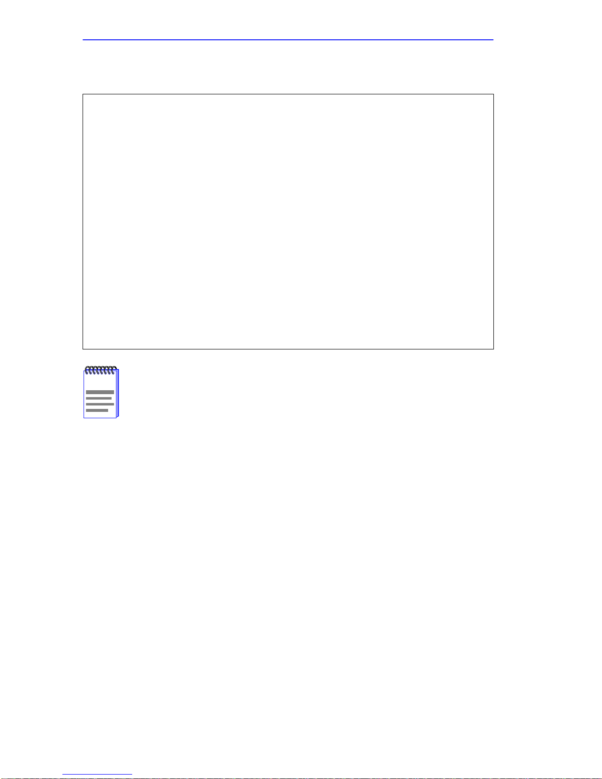
The command display looks like this:
monitor:: console-baud
Remote Diagnostic Test Mode
In order to use the remote diagnostic functionality, you
must first connect a modem to the console port of the
Annex. The modem should be configured such that DTR is
forced on, carrier detect and DSR are set normal, and
auto-answer is enabled. Once this is done, contact your
service representative for remote diagnostic maintenance.
To enter “Autobaud Mode”, please type “Auto”. To
“manually” configure the Annex console port, please type
in the desired baud rate. To return to the “monitor::”
prompt strike the “carriage return <CR>” key.
[Baudrate Range: 50-9600 BAUD]
Select Baudrate []::
This command has no effect on the port’s baud rate after the
NOTE
CSMIM2 is booted
To provide remote access to the CSMIM2 ROMs:
1. From a site local to the CSMIM2:
• Set the CSMIM2 into test mode so the monitor prompt appears on
the console.
• Set the modem into auto-answer mode.
2. From the CSMIM2 console port:
• At the monitor prompt, enter console-baud.
• At the Select baud rate prompt, enter the appropriate baud rate or
auto.
• Connect the modem to the CSMIM2’s console port.
3-12 CSMIM2 Installation Guide
Page 47

3. From the remote site:
• Dial into the modem connected to the CSMIM2.
Commands
• Type
RETURN until the monitor prompt appears.
3.2.5 erase
The erase command erases the contents of non-volatile memory,
including the CSMIM2’s IP address. This command also restores the
parameters to their factory defaults. The syntax is:
erase
If the self-boot option is installed, the erase command prompts for which
non-volatile memory to erase: EEPROM or FLASH. Entering 1 at the
prompt causes the CSMIM2 to erase the EEPROM memory
(configuration information); entering 2 at the prompt causes the CSMIM2
to erase the Flash memory (self-boot image).
The erase command display looks like this:
monitor:: erase
1) EEPROM (i.e. configuration information)
2) FLASH (i.e. self boot image)
Enter 1 or 2 :: 1
Erase all non-volatile EEPROM memory? (y/n) [n]:: y
Erasing <16352 or 8160 bytes> of non-volatile memory.
Please wait . . .
16K->|Data 0xff
. . . . . . . . . . . . . . . . . . . . . . . . . . . . . .
16K->|Data 0x0
. . . . . . . . . . . . . . . . . . . . . . . . . . . . . .
Initialized checksum record installed
.
.
.
CSMIM2 Installation Guide 3-13
Page 48
Chapter 3: ROM Monitor Commands
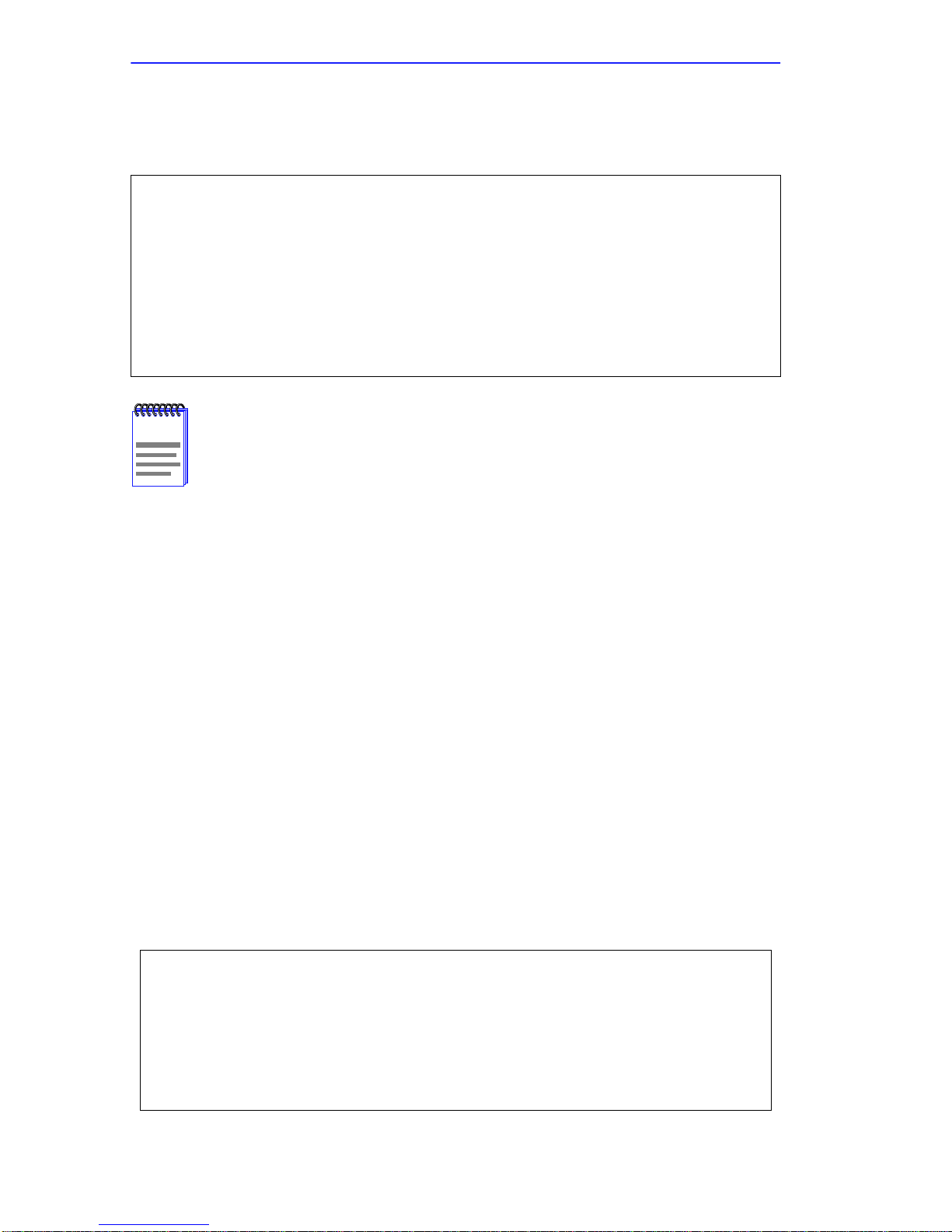
If the self-boot option is not installed, the command display looks
like this:
monitor:: erase
Erase all non-volatile EEPROM memory? (y/n) [n]:: y
Erasing <16352 or 8160 bytes> of non-volatile memory.
Please wait . . .
16K->|Data 0xff
. . . . . . . . . . . . . . . . . . . . . . . . . . . . . .
16K->|Data 0x0
. . . . . . . . . . . . . . . . . . . . . . . . . . . . . .
Initialized checksum record installed
The erase command does not erase the Ethernet address.
NOTE
Since the erase command erases the IP address, you
use the addr command to re-enter the CSMIM2’s IP address
before reloading any software.
must
3.2.6 help
Entering help, or ?, displays brief descriptions of the CSMIM2 ROM
Monitor commands.
3.2.7 image
The image command sets and displays the name of the image file
containing the CSMIM2’s software. The command syntax is:
image [–d | filename]
The filename argument permits up to 100 characters. To return the image
name to its default, enter a pair of double-quote characters (""). The
default image name is oper.56.enet. The image command display looks
like this:
monitor:: image
Enter Image name: [(ip) "oper.56.enet", (mop)
"OPER_56_ENET.SYS"]::
Enter TFTP Load Directory [""]::
Enter TFTP Dump path/filename ["dump.192.9.200.88"]::
3-14 CSMIM2 Installation Guide
Page 49
The image –d command display looks like this:
monitor:: image -d
Image name: Default (ip): "oper.56.enet"
Default (mop): "OPER_56_ENET.SYS"
TFTP Load Directory: ""
TFTP Dump path/filename: "dump.192.9.200.88"
SELF image name: "oper.56.enet"
The
NOTE
SELF image name
is loaded.
appears only if the self-boot image
If the image file name contains more than 16 characters, it is
truncated when MOP is attempted.
3.2.8 ipx
Commands
The ipx command sets several parameters associated with IPX booting
and dumping. This is useful when loading the CSMIM2’s operational
image from a Novell file server. The command syntax is:
ipx [–d]
The ipx command display looks like this:
monitor:: ipx
Enter IPX file server name [<uninitialized>]::mars
Enter Frame type, 0=802.3 1=Ethernet II 2=802.2 3=SNAP\
[802.3]::
Enter IPX dump user name [<uninitialized>]::susans
Enter IPX dump password [<uninitialized>]::********
Verify IPX dump password []::********
Enter IPX dump path [<uninitialized>]::SYS:\user\susans\
CSMIM2 Installation Guide 3-15
Page 50
Chapter 3: ROM Monitor Commands
The ipx –d command displays the current settings for all of the entries.
The command display looks like this:
monitor:: ipx -d
IPX preferred load file server: "MARS"
IPX Frame type: “802.3”
IPX dump user name: "SUSANS"
IPX dump password: <SET>
IPX dump path name: "SYS:\user\susans\"
3.2.9 lat_key
The lat_key command allows you to set the LAT key from the ROM
monitor.
The lat_key command is optional and may be purchased
NOTE
separately.
The command syntax is:
lat_key [–d]
The lat_key command display looks like this:
monitor:: lat_key
Enter LAT_KEY: [<uninitialized>]::
The
lat_key –d command displays the current LAT key setting:
monitor:: lat_key -d
LAT_KEY: <uninitialized>
3-16 CSMIM2 Installation Guide
Page 51
Commands
3.2.10 mop
The mop command sets the MOP load/dump address. This is useful when
the loading the CSMIM2’s operational image from a VAX VMS load
host. The command syntax is:
mop [–d]
The mop command display looks like this:
monitor:: mop
Enter preferred MOP load/dump address [<uninitialized>]::
Load Broadcast Y/N [Y]::
The
mop –d command displays the current MOP settings:
monitor:: mop -d
MOP preferred load/dump address <uninitialized>
Load Broadcast: Y
3.2.11 net
The net command executes an Ethernet transceiver loopback test on the
local area network. The command syntax is:
net
The net command display looks like this:
monitor:: net
Network test – PASSED
This transciever loopback test sends out a short test packet from the
CSMIM2 through the MMAC backplane to test the integrity of the
network. One of the Ethernet backplane channel connections must be
active and valid for this test to pass.
CSMIM2 Installation Guide 3-17
Page 52
Chapter 3: ROM Monitor Commands
If the unit passes this test, the console displays PASSED. If the CSMIM2
fails, the console displays an error message. Failing this test indicates that
the CSMIM2 failed to communicate with the MMAC chassis backplane.
Contact Cabletron Systems Technical Support.
3.2.12 option_key
The option_key command loads an option key from the ROM monitor.
The command syntax is:
option_key [–d ]
The option_key command display looks like this:
monitor:: option_key
Enter option_key [<uninitialized>]::
The option_key –d command displays the current settings:
monitor:: option_key -d
option_key: <uninitialized>
3.2.13 ping
The ping command sends an Internet Control Message Protocol (ICMP)
mandatory ECHO_REQUEST datagram to elicit an ICMP
ECHO_RESPONSE from a host or gateway. ECHO_REQUEST
datagrams (pings) have an IP and ICMP header, followed by a structured
time value and an arbitrary number of pad bytes that fill out the packet.
The syntax for this command is:
ping host_ip_address [data_size] [npackets]
The host_ip_address entry is the Internet address of the host or gateway
from which you wish to elicit a response.
The optional data_size entry is the number of bytes sent in a datagram
packet. The default value is 64 and the maximum value is 1024.
3-18 CSMIM2 Installation Guide
Page 53

Commands
The optional npackets entry is the number of packets to transmit. If you
specify npackets, then you must also specify a data_size.
The ping command display looks something like this:
monitor:: ping 132.245.33.69
PING 132.245.33.69: 64 data bytes
To exit out of
point, type
ping either wait for npackets to be transmitted or, at any
q. The ping statistics display upon exit.
3.2.14 ports
The ports command tests serial line ports, exercising both the data lines
and the control lines for each serial port specified. The syntax for this
command is:
ports [–d]
Each serial port to be tested must be looped-back with a loopback plug to
test both the data lines and the control lines (the accessory kit provides a
loopback plug). Connect this plug to the connector on the CSMIM2 that
corresponds to the port to be tested.
Do not run the ports command for a port to which a device is
NOTE
connected. The test will transmit data to the device and toggle
its control lines.
CSMIM2 Installation Guide 3-19
Page 54

Chapter 3: ROM Monitor Commands
When invoked, the command displays a menu of options.
monitor:: ports
Individual Port Tests (Data and Control Lines)
Some important notes:
- All Serial Ports (1-7) which are to be tested require a
loopback plug in order to pass the Data Line and Control Line
loopback tests.
WARNING. If there is a device instead of a loopback plug
connected to the port being tested, the device will have data
transmitted to it and its Control Line toggled.
Ports with faulty Control Lines:
Ports with faulty Data Lines:
Enter port number or range of ports to test (Return to exit):: 3
Enter the number of times to loop on this test [1]::
Testing data lines on channel 3
ERROR -- Data line loopback failure on port 3 Testing modem
signals on channel 3
ERROR -- No RTS/CTS turning (ON) loopback interrupt sensed on
Chan 3 !
Pressing the RETURN key after the prompt Selection (Return to exit)
returns you to the monitor prompt.
3-20 CSMIM2 Installation Guide
Page 55

Commands
If you enter the ports –d command, only the data lines are tested. The
outgoing control lines are asserted during this test.
monitor:: ports -d
Individual Port Tests (Data Lines)
Some important notes:
- All Asynch Serial Ports (2-16) which are to be tested require a
loopback plug in order to pass the Data Line loopback tests.
WARNING. If there is a device instead of a loopback plug
connected to the port being tested, the device will have data
transmitted to it.
You may enter a list of ports to test separated by spaces/commas.
You may also enter ranges of ports, such as 2-16.
Ports with faulty Data Lines: 3
Enter port number or range of ports to test (Return to exit)::
3.2.15 sequence
The sequence command edits the load/dump interface list. This list
determines the order of the network interfaces, and either the local area
network (LAN) or the SLIP interface the CSMIM2 will use for loading
and dumping. The default, net, uses the LAN interface. The list can
contain up to four interfaces. If the CSMIM2 fails to boot using the first
interface, it will try the next, and then the next interface, and then repeat
the sequence. The command syntax is:
sequence [–d] | [interface[,interface]. . .]
Specify the LAN interface by selecting net; specify each SLIP interface
as slnn, where nn is a port number; and specify self-boot by selecting self.
Separate each interface with a comma or a space. Enter the interface list
as an argument to the command; otherwise, the console displays a list of
available interfaces and prompts for a new list.
In the following example, interfaces are assigned to the load/dump
sequence list. Ports 12, 14, and 15 can be added to the list because they
were configured earlier as SLIP interfaces:
CSMIM2 Installation Guide 3-21
Page 56
Chapter 3: ROM Monitor Commands
monitor:: sequence
Enter a list of 1 to 4 interfaces to attempt to use for
downloading code or upline dumping. Enter them in the order
they should be tried, separated by commas or spaces. Possible
interfaces are:
Ethernet: net
SL/IP: sl12,sl14,s115
SELF: self
Enter interface sequence [net]:: sl12, net
Interface sequence: sl12,net
The
SELF
NOTE
option appears only if the self-boot image is loaded.
If you enter the command with the –d argument, the console displays the
current load/dump interface list. You cannot specify both the –d argument
and the interface list with the same command. The sequence –d
command display looks like this:
monitor:: sequence -d
Interface sequence: sl12,net
Entering a number for a port that has not been configured properly for
SLIP causes the Port nn is not configured for SL/IP message to display,
where nn is the port number.
The CSMIM2 can slip boot over any port except Port 1.
NOTE
3-22 CSMIM2 Installation Guide
Page 57

Commands
3.2.16 slip
The slip command defines a serial port as a Serial Line Internet Protocol
(SLIP) interface. This command defines a number of port parameters.
The command syntax is:
slip [–d] [port]
After entering the command, you are prompted for each parameter. The
port is the number of the serial port to be configured with this command.
If you do not enter a port number, you will be prompted for one. Table
3-2 lists the information for which the slip command prompts.
Entering slip –d causes the command to display all the current settings.
Table 3-2 The slip Command Prompts
Prompt Description
Modifies the port’s mode. A y response changes
the port to a SLIP interface. An n response changes
Allow SLIP on this port
Enter local endpoint
address
Enter remote
endpoint address
Enter remote
load/dump host
address
Should this interface
be used for memory
dumps
the port’s mode to CLI. The port is not available as
a SLIP interface and the SLIP parameters are
ignored. The default is n.
Specifies the CSMIM2 IP address for this SLIP
interface. The CSMIM2 boots over the SLIP
interface only if this address is set.
Specifies the IP address of the remote end of the
SLIP interface.
Specifies the IP address of the remote host to
which load and dump requests are sent. This
address is required only if the remote host is a
gatewa y and not the load host. By def ault, this is the
same as the remote end-point address.
Enables the CSMIM2 to use a SLIP interface for
memory dumps. The default is y.
Enter the baud rate
CSMIM2 Installation Guide 3-23
Specifies the baud rate of the serial interface. The
default is 9600.
Page 58

Chapter 3: ROM Monitor Commands
Table 3-2 The slip Command Prompts
Prompt Description
Enter the number of
stop bits
Pressing the RETURN key accepts the default
(one). Generally, SLIP implementations require
the default.
Pressing the RETURN key accepts the default
Enter the parity
(none). Generally, SLIP implementations require
the default.
The slip command automatically sets the number of data bits to 8 for all
SLIP interfaces. The number of data bits does not include the start, stop,
or parity bits. The slip command display looks like this:
monitor:: slip
Line number (1-16):: 6
Allow SL/IP on this port? (y/n) [n]:: y
Enter local endpoint address [0.0.0.0]:: 192.9.200.214
Local endpoint address: 192.9.200.214
Enter subnet mask [255.255.255.0]::
Constructed new subnet mask.
Enter remote endpoint address [0.0.0.0.]:: 192.9.200.0
Remote endpoint address: 192.9.200.0
Enter remote load/dump host address [default 192.9.200.88]::
Using remote endpoint address: 192.9.200.88
Should this interface be used for memory dumps? (y/n) [y]::
Enter the baud rate [9600]::
Enter the number of stop bits (1,1.5,2) [1]::
Enter the parity (none,even,odd) [none]::
Pressing CONTROL + C interrupts the slip command; the
NOTE
parameters remain unchanged until the command completes
normally.
3-24 CSMIM2 Installation Guide
Page 59

Commands
3.2.17 stats
The stats command displays current network statistics gathered by the
ROM. Use stats along with the boot command to help isolate problems.
Table 3-3 describes the network statistics displayed by the stats
command. The syntax is:
stats [-slip]
The stats command display looks like this:
monitor:: stats
Ethernet Statistics
Frames Received: 398 Frames Sent: 3
CRC Errors: 0 Carrier Sense Losses: 0
Alignment Errors: 0 Clear to Send Losses: 0
Resource Drops: 0 Collisions Detected: 0
Bus Wait Drops: 0 Excessive Collision Losses 0
Bad Types/Lengths: 0
Table 3-3 Network Statistics
Statistic Description
Frames Received The number of frames received.
CRC Errors The number of CRC checksum errors detected.
Alignment Errors
Resource Drops
Bus Wait Drops
The number of frames received misaligned with a CRC
error.
The number of packets dropped because the ROM
code could not buffer them quickly enough. The ROM
code cannot always handle back-to-back incoming
packets. The CSMIM2 accepts the first response it
receives and drops all others. Dropped packets are
normal.
The number of packets dropped due to waiting too
long for a bus to become available.
CSMIM2 Installation Guide 3-25
Page 60

Chapter 3: ROM Monitor Commands
Table 3-3 Network Statistics (Continued)
Statistic Description
The number of unknown packet types if Ethernet IP
Bad Types/
Lengths
Frames Sent The number of frames sent.
encapsulation is being used. The number of packets
with illegal lengths if IEEE 802.2/802.3 IP
encapsulation is being used.
Carrier Sense
Losses
Clear to Send
Losses
Collisions Detected
Excessive Collision
Losses
The number of times packets could not be transmitted
because the CSMIM2 lost the Carrier Sense signal –
usually the result of excessive traffic on the Ethernet.
The number of times packets could not be transmitted
because the CSMIM2 lost the Clear to Send signal –
usually the result of excessive traffic.
The number of times the CSMIM2 had to retry
transmissions automatically – usually the result of
normal Ethernet traffic. These retries do not cause the
boot command to display ‘‘*.”
The number of times the CSMIM2 could not transmit
packets because there were too many collisions –
usually the result of excessive traffic on the Ethernet.
The boot command displays these retries as “*.”
3-26 CSMIM2 Installation Guide
Page 61

CHAPTER 4
TROUBLESHOOTING PROCEDURES
4.1 GENERAL
The CSMIM2’s front panel displays 4 system indicators and 16 or 32
status indicators. The system indicators are labeled Stat, Traf, Attn, and
S/U. The status indicators are numbered 1 through 32. The MODMIM
and the MODEXT cards display 5 LED indicators, CTS, DTR, TXD,
RXD, DCD, per modem port.
The system indicators provide information about normal operations and
about problems that occur. Use these indicators and the ROM Monitor
commands to diagnose problems.
The status indicators display port activity during normal operations; each
indicator supports 1 port.
During power-up and booting, it is more complicated to diagnose
problems because they can originate in the CSMIM2 or the load server
host. However, the indicators provide both a progress report and an error
display to assist you in troubleshooting.
4.2 POWER-UP AND BOOT PROCEDURES
The CSMIM2 has two modes of operation: normal and Set Up. Normal
mode is the standard operational mode. Set Up mode provides access to
the ROM Monitor commands. Pressing the Set Up switch on the front
panel, within 30 seconds of powering–up, puts the CSMIM2 into Set Up
mode. When the CSMIM2 is in Set Up mode, the S/U indicator lights.
Figure 1-3 in Chapter 1 illustrates the CSMIM2’s front panel.
During the power-up and boot sequence, the CSMIM2 performs a set of
diagnostics. The system indicators display the diagnostics’ status. The
CSMIM2 stops when it detects one of two error conditions (see Table
4-2). The pattern of the system indicators identifies the error condition.
CSMIM2 Installation Guide 4-1
Page 62

Chapter 4: Troubleshooting Procedures
4.2.1 Normal Mode
Upon power–up or reset, the CSMIM2 enters normal mode. The
following subsections describe both the possible error, and error-free,
conditions that can occur during power-up and booting in normal mode.
4.2.1.1 Normal Mode Error-free Sequence
Table 4-1 summarizes the indicator display sequences during error-free
power-up in normal mode.
Table 4-1 Normal Mode Error-free Indicator States
Activity
N1: Indicators OK
N2: Hardware OK
Stat
green
● ● ●
● ✕ ■
Attn
red
Traf
green
Key: ● = On continuously ✕ = Off ■ = Flashing irregularly
= Flashing regularly (about 1Hz)
◆
4.2.1.2 Activity N1: Testing Indicators
All front panel indicators light for a few seconds, then all but the
Ethernet channel indicator (segment indicator) turn off, confirming that
all indicators are operational.
4.2.1.3 Activity N2: Testing the Hardware
During the power-up sequence, the CSMIM2 runs a series of self-test
diagnostics. These diagnostics test internal hardware functions. If a test
fails, the Attn and Stat LEDs flash and an error message is displayed if
the console port is selected. The Ethernet Channel indicator lights for a
few seconds, then the Traf indicator flashes during the power-up
self–tests. After the self–tests complete, only the Stat and Ethernet
Channel indicators remain on.
4-2 CSMIM2 Installation Guide
Page 63
Power-up and Boot Procedures
4.2.1.4 Normal Mode Error States
Table 4-2 shows the state of the indicators when an error occurs at given
stages of the start-up process. For example, if the CSMIM2 fails during
the testing hardware state (N2), the error condition is hardware failure
NE2. A description of possible causes and solutions for each error
condition follows Table 4-2.
Table 4-2 Normal Mode Error Indicator States
Activity
NE2: Hardware failure
NE5: Booted wrong image
Stat
green
◆ ◆ ✕
● ◆ ✕
Attn
red
Traf
green
Key: ● = On continuously ✕ = Off ■ = Flashing irregularly
◆ = Flashing regularly (about 1Hz)
4.2.1.5 Activity NE2: Hardware Failure
The ROM diagnostics detected a CSMIM2 hardware problem requiring
service. Call technical support.
4.2.1.6 Activity NE5: Booted Wrong Image
The CSMIM2 has just loaded an inappropriate image. Pressing the Set
Up switch for approximately 3 seconds to generate a reset clears this
error. The CSMIM2 loads inappropriate images if one of the following
operator errors occur:
• Configuring the CSMIM2 with an incorrect file name, or renaming or
copying the image file to the wrong name.
• Supplying the wrong name to any of the boot commands (na boot,
dumpboot, or the superuser CLI boot).
If you are uncertain as to why the CSMIM2 booted the wrong image,
enter Set Up mode and issue an image -d command. This command
shows which host file the CSMIM2 is trying to load.
CSMIM2 Installation Guide 4-3
Page 64
Chapter 4: Troubleshooting Procedures
4.2.2 Set Up Mode
Pressing the Set Up switch within 30 seconds of either a reset or cycling
on power puts the CSMIM2 into Set Up mode. The S/U indicator is on
after pressing the Set Up switch.
4.2.2.1 Set Up Mode Error-free Sequence
Table 4-3 summarizes the indicator sequences that display in test mode
during an error-free start-up. A description of each sequence follows
Table 4-3.
Table 4-3 Test Mode Error-free Indicator States
Activity
T1: Testing Indicators
T2: Testing hardware
T3: At monitor prompt
Stat
green
● ● ●
● ✕ ■
● ● ■
Attn
red
Traf
green
Key: ● = On continuously ✕ = Off ■ = Flashing irregularly
◆ = Flashing regularly (about 1Hz)
4.2.2.2 Activity T1: T esting Indicators
All front panel indicators, except the non-selected segment LEDs, light
for a few seconds, then all but the Ethernet Channel indicators turn off.
This sequence confirms that all indicators are operational. At this point,
the CSMIM2 is in normal mode. Press the Set Up switch to put the
CSMIM2/MODMIM into monitor mode.
4.2.2.3 Activity T2: T esting the Hardware
During power-up, the CSMIM2/MODMIM runs self-tests that execute
CPU diagnostics, ROM and E2 PROM, flash checksums, refresh, internal
serial port and LAN loopbacks, and RAM tests. The Traf indicator
flashes during the tests and after completing the power-up self-tests, the
Stat and Ethernet channel indicators remain on.
4-4 CSMIM2 Installation Guide
Page 65

Power-up and Boot Procedures
4.2.2.4 Activity T3: At the Monitor Prompt
When the Stat and Attn indicators are on, the ROM Monitor prompt
displays on the console terminal. Enter the boot command at the prompt.
If you did not enter a file name with the command, a prompt asks you for
one.
4.2.2.5 Set Up Mode Error States
Table 4-4 describes the state of the indicators if errors occur at different
stages of the start-up process. For example, if the CSMIM2 fails while
testing the hardware (state T2), the error condition is hardware failure
TE2. A description of each error condition follows Table 4-4.
Table 4-4 Test Mode Error Indicator States
Activity
TE2: Hardware failure
TE7: Booted wrong image
Stat
green
◆ ◆ ✕
● ◆ ✕
Attn
red
Traf
green
Key: ● = On continuously ✕ = Off ■ = Flashing irregularly
= Flashing regularly (about 1Hz)
◆
4.2.2.6 Activity TE2: Hardware Failure
The ROM diagnostics detected a CSMIM2 hardware problem requiring
service. Call technical support.
4.2.2.7 Activity TE7: Booted Wrong Image
The CSMIM2 loaded an inappropriate image. Pressing the Set Up switch
approximately 3 seconds to generate a reset clears this error. The
CSMIM2 loads inappropriate images if one of the following operator
errors occurs:
• Configuring the CSMIM2 with an incorrect file name, or renaming or
copying the image file to the wrong name.
• Supplying the wrong name to the boot command.
CSMIM2 Installation Guide 4-5
Page 66

Chapter 4: Troubleshooting Procedures
4.3 BOOT FAILURES
The procedures for troubleshooting a power-up failure established that:
• the hardware is functional
• the Ethernet interface is functional
• the CSMIM2 can communicate with the Ethernet.
If the CSMIM2 still is not booted, you must pinpoint the problem. The
boot error report can help in this process.
The CSMIM2 generates a boot error report only if it opens the
NOTE
boot file and an error occurs during the boot process.
Generally, two problems cause boot failures: the CSMIM2 is not
configured properly, or the load server host is not responding. The
CSMIM2 requests a boot either from a pre-defined load host, or by
broadcasting its boot request. When a host responds, the CSMIM2 loads
its operational code.
The CSMIM2 requires setting certain configuration parameters. Enter
these parameters with ROM Monitor commands for the initial boot
sequence. See Chapter 3 for more information on these commands.
If the problem is a non–responsive host, the boot error report displays that
information under the Rsp T/O’s: field. This field indicates that the
CSMIM2 timed out while waiting for a response to its boot request; if this
field is empty, check the CSMIM2’s configuration parameters.
4-6 CSMIM2 Installation Guide
Page 67

Boot Failures
4.3.1 Boot Error Report
If an error occurs, a boot error report is generated only if the CSMIM2 has
opened the boot file. The report uses the following format:
BOOT ERROR REPORT (for BFS files only)
Boot attempt from host nn.nn.nn.nn:
Errors from Last Open Request:
0 ARP errors 0 ERPC layer errors 0 Aborts rx’d
Errors from Last Read Request:
0 Msgs w/ wrong size 0 ERPC layer errors 0 Aborts rxd
Errors from Last ERPC Layer Invocation:
0 H/W errors 1 Msgs from wrong host 0 Rsp T/O’s
0 Msgs of wrong type
TFTP error reporting complies with the standard, pre-defined
NOTE
TFTP error codes.
The CSMIM2 generates a boot error report for the Internet address from
which it tried, and failed, to boot. Table 4-5 describes the Errors from
Last Open Request; Table 4-6 describes the Errors from Last Read
Request; and Table 4-7 describes the Errors from Last ERPC Layer
Invocation.
The error count pinpoints the error that caused the boot failure. For
example, if the boot failed during a Read Request due to excessive
Expedited Remote Procedure Call (ERPC) layer errors, the Errors from
Last ERPC Layer Invocation lists only errors that occurred during the
failed Read Request. The report does not list errors that occurred during
any other Read Request or during the Open Request.
The Open Request and the Read Request layers communicate with the
block file server (BFS) on the host. The ERPC layer resides below the
Open Request and the Read Request layers. It is responsible for sending a
given message to a specific host UDP port, and for receiving the correct
response to that message from the port.
CSMIM2 Installation Guide 4-7
Page 68

Chapter 4: Troubleshooting Procedures
Table 4-5 Errors from Last Open Request
Address Resolution Protocol (ARP) errors indicate that
the CSMIM2 is configured to boot from a specified host,
ARP errors
ERPC layer errors See Errors from Last ERPC Layer Invocation below.
Aborts rx’d
but the host would not transmit its Ethernet address to the
CSMIM2. Possibly, the CSMIM2 configuration includes
the wrong IP encapsulation.
The host’s BFS transmitted an abort in response to the
CSMIM2’s Open Request. This often means that the
requested file does not exist on that server. Run erpcd -D
on the host to obtain more information.
Table 4-6 Errors from Last Read Request
Msgs with wrong size
The correct host responded to the Read Request, but the
data size is incorrect.
ERPC layer errors See Errors from Last ERPC Layer Invocation below.
The host’s BFS transmitted an abort in response to the
Aborts rx’d
CSMIM2’s Read Request. Run erpcd -D on the host to
obtain more information.
Table 4-7 Errors from Last ERPC Layer Invocation
The CSMIM2 sensed a hardware error during
message transmission or reception. This error
H/W errors
indicates a fault with the CSMIM2 network interface.
Use the net command to isolate the problem (see
Chapter 3).
The CSMIM2 received a message from an incorrect
Msgs from wrong host
host. This indicates that the CSMIM2 received, and
ignored, an unsolicited packet.
The CSMIM2 never received a correctly formatted
Rsp T/O’s
response from the correct host, or any response
from any load server hosts.
Msgs of wrong type
4-8 CSMIM2 Installation Guide
The correct host sent a message to the CSMIM2,
but the message was not a correctly formatted
response to the transmitted request.
Page 69

Boot Failures
4.3.2 Correcting CSMIM2 Parameters
The following parameters must accurately reflect both the CSMIM2 and
the network environment in which it operates:
• Verify the CSMIM2’s Internet address using the addr command.
• If your network configuration does not support the factory defaults,
verify the following parameters using the addr command:
- The broadcast address.
- The subnet mask.
- The load/dump gateway address (which must be specified if the
preferred load server host is located on another network or
subnet).
- The IP encapsulation type. Many systems hav e hardware Ethernet
interfaces that are IEEE 802.3 compliant, but very fe w actually do
802.3 IP packet encapsulation. Use the default, Ethernet, unless
you know absolutely that your LAN does 802.2/802.3 IP packet
encapsulation.
• Unless otherwise stated, if you are using a SLIP interface to boot the
CSMIM2, verify the following using the slip command:
- The port is configured as a SLIP interface.
- The Internet address for the SLIP network interface.
- The Internet address for the remote end of the SLIP connection.
- The Internet address for the load/dump host (this must be specified
if the remote end is a gateway and not a load host).
- The SLIP network interface is included in the load/dump interface
list (use the sequence command).
Both the name of the image file containing the CSMIM2’s software, and
the address of the preferred load server host can be defaulted. If the value
for the image name is incorrect, the CSMIM2 cannot boot. Correct the
name using the image command. If the address for the preferred load
server host is incorrect, the boot takes longer, since the CSMIM2 has to
broadcast for a host. Correct the load host’s address using the addr
command.
CSMIM2 Installation Guide 4-9
Page 70

Chapter 4: Troubleshooting Procedures
Confirm that the CSMIM2 boot parameters are correct by using the
appropriate ROM Monitor commands. Modify any boot parameters that
are incorrect or missing. Boot the CSMIM2 either by entering the boot
command at the console, or by pressing the Set Up switch approximately
3 seconds to generate a reset, followed by an automatic boot.
4.3.3 Load Server Host Not Responding
The CSMIM2 can boot from one of four types of hosts acting as a load
server host:
• A UNIX host on the local area network.
• A UNIX host at the end of a SLIP interface.
• Another CSMIM2.
• Any host (UNIX or non-UNIX, using tftp).
The following subsections discuss troubleshooting for each of these load
server hosts.
4.3.4 UNIX Host on the LAN
When troubleshooting a UNIX host on the LAN, make sure:
• The host is booted and functioning properly.
• The host can communicate with other network nodes using standard
UNIX networking features and utilities.
• All CSMIM2 software is installed properly on the host. (See the
CSMIM2 Installation Notes.)
• The erpcd daemon or tftp server, which loads the operational image
to the CSMIM2, is running.
ps -ef | grep erpcd
4-10 CSMIM2 Installation Guide
Page 71

Boot Failures
In Set Up mode, both the CSMIM2 and erpcd on the load server host
display boot progress reports. The CSMIM2 displays its reports on the
console; erpcd displays its reports on the terminal that invokes test mode.
• To place the CSMIM2 into Set Up mode, press the Set Up switch after
a reset and wait for monitor prompt.
• To place erpcd on the load server host into test mode, kill the erpcd
program (requires superuser privileges) and restart it using the -D
option:
# /etc/erpcd -D
When the CSMIM2 boots in Set Up mode, the console displays the load
server host’s Internet address, and indicates whether it receives a response
to its Open File Request and to any of its Read File Requests. The host’s
progress report indicates receipt of any File Server Requests and its
responses to such requests. The host displays erpc_return 0 if it
successfully receives a request and is sending out an affirmative response.
If any CSMIM2-related files are missing or cannot be installed, contact
technical support.
4.3.5 UNIX Host on a SLIP Interface
When troubleshooting a UNIX host at the end of a SLIP network
interface, make sure:
• The host is booted and functioning properly.
• The SLIP link is connected correctly.
• The Internet addresses are correct for both sides of the SLIP link.
• All CSMIM2 software is installed properly on the host. See the
CSMIM2 Installation Notes.
• The erpcd daemon or tftp server, which loads the operational image
to the CSMIM2, is running.
A PC host running the XENIX operating system has both the erpcd and
slipd daemons (provided with the distribution and installed in the file
/etc) running in the background on the PC. Set the CSMIM2 and the
erpcd on the load host into Set Up mode:
CSMIM2 Installation Guide 4-11
Page 72

Chapter 4: Troubleshooting Procedures
• For the CSMIM2, press Set Up following a reset and wait for the
monitor prompt.
• For erpcd on the load server host, as superuser , kill the erpcd program
and restart it using the -D option:
# /etc/erpcd -D
4.3.6 Another CSMIM2
When troubleshooting a CSMIM2 configured as a load server host:
• Use the CLI telnet command to access the unit and verify that it is up
and running.
• Communicate with the unit on the Ethernet using the superuser CLI
ping command.
• Verify the unit’s configuration using na.
The CSMIM2 Network Administrator’s Guide provides more information
on these commands.
A CSMIM2 that has been reconfigured as a load server host, but not
rebooted, cannot boot another CSMIM2 on the network. Rebooting the
CSMIM2 load server host ensures that the parameters are set.
4.3.7 CSMIM2 Dumps
The CSMIM2 dumps its memory image to a host running load server
software when certain software or hardware events occur. Events that
trigger CSMIM2 dumps are:
• Non-recoverable hardware or software errors.
• Software fails to reset the CSMIM2’s watchdog timer.
• Software fails one or more internal consistency checks.
• Hardware detects an internal fault.
Dump files are generated for use by technical support
NOTE
4-12 CSMIM2 Installation Guide
personnel only.
Page 73

Table 4-8 Indicator States during a Dump
Boot Failures
Activity
Dump l l n
Stat
green
Attn
red
Traf
green
Key: ● = On continuously ■ = Flashing irregularly
The CSMIM2 sends a dump file to a preferred load dump host. If you do
not define this host by specifying an address, the CSMIM2 broadcasts a
request and dumps to the first host that responds.
The dump creates a file in the dump host’s directory, named
/usr/spool/erpcd/bfs, and assigns a unique file name for each CSMIM2
but not for each crash dump. For each dump, the CSMIM2 overwrites the
existing file.
The assigned name depends on the number of characters per file name
that the dump host supports. For hosts supporting file names longer than
14 characters (e.g., BSD hosts), dump files are named dump.addr. The
file extension addr is the CSMIM2’s Internet address.
For hosts that limit file names to 14 characters (e.g., System V hosts), a
dump creates two additional directories under /usr/spool/erpcd/bfs. The
name of the first directory is dump; the second directory uses the
CSMIM2’s Internet network address as its name. The dump file uses the
CSMIM2’s Internet host address as its name.
Each dump file contains a complete image of the CSMIM2 RAM memory
and hardware state. The amount of space required for a dump file varies
according to the port configuration. The ROM Monitor config command
displays the amount of memory for the CSMIM2. Table 4-9 shows
sample dump file names. All pathnames are relative to the file
/usr/spool/erpcd/bfs.
Table 4-9 Dump File Naming Conventions
CSMIM2
Address
63.0.0.75 63 dump.63.0.0.75 dump/63/0.0.75
Network
Address
BSD
Filename
System V
Pathname
131.140.23.1 131.140 dump.131.140.23.1 dump/131.140/23.1
195.46.2.15 195.46.2 dump.195.46.2.15 dump/195.46.2/15
CSMIM2 Installation Guide 4-13
Page 74

Chapter 4: Troubleshooting Procedures
The tftp dump names are user–defined. If a name is not
NOTE
specified, the CSMIM2 uses the bfs convention.
4.4 MODMIM T ROUBLESHOOTING
The MODMIM uses the same indicators as the CSMIM2-16 for its 16
asynchronous ports with the addition of 5 LEDS and a reset switch per
modem port. In normal operation, the port status indicators are as follows:
Table 4-10 MODMIM Port Status Indicators
CTS
DTR
TXD
RXD
DCD
Clear to Send
hardware flow control is enabled (&H1, &H3). Always on during
synchronous connections.
Data Terminal Ready
from the computer or terminal.
Send Data.
the MODMIM.
Received Data
passes received data bits to the computer or terminal.
Carrier Detect
(carrier) from a remote modem, indicating that data transmission is
possible.
. ON until the modem lowers CTS when Transmission Data
. ON when the MODMIM receives a DTR signal
Flashes when the computer or terminal sends a data bit to
. Flashes when the MODMIM sends result codes or
. On when the MODMIM receives a valid data signal
4-14 CSMIM2 Installation Guide
Page 75
APPENDIX A
PORT PIN/SIGNAL ALLOCATIONS
A.1 GENERAL
This appendix identifies the signals and the associated pins used by the
following CSMIM2 ports:
• Console
• Serial
Port 1 of the CSMIM2/MODMIM serves as a console port only
NOTE
during Set Up. At all other times, port 1 acts as a serial port.
A.2 CONSOLE PORT
When the CSMIM2 is in Set Up mode, port 1 becomes the console port.
Table A-1 Console Port Pinouts
RJ45 Pin Signal
1 Unused
2 DTR
3 TXD
4 DCD
5 RXD
6 GND
7 DSR
8 Unused
CSMIM2 Installation Guide A-1
Page 76
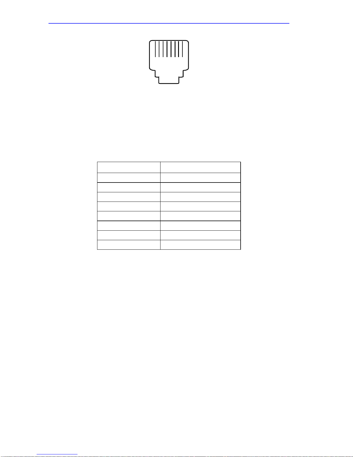
Appendix A: Port Pin/Signal Allocations
1 8
Front
Figure 1-1 RJ45 Console Port Receptacle
A.3 SERIAL PORT
Table A-2 RJ45 Serial Port Pin/Signal Allocations
RJ45 Pin Signal
1 RTS
2 DTR
3 TXD
4 DCD
5 RXD
6 GND
7 DSR
8 CTS
A-2 CSMIM2 Installation Guide
Page 77

APPENDIX B
CONNECTORS
B.1 GENERAL
This appendix describes the wiring for the following connectors:
• DTE (Cabletron part number 9372074) for DB25 female
• DTE (Cabletron part number 9372082) for DB25 male
• DTE (Cabletron part number 9372076) for DB9 female
• DCE (Cabletron part number 9372083) for DB25 female
• DCE (Cabletron part number 9372075) for DB25 male
Table B-1 RJ45 Pinouts
RJ45
Pin
1 RTS OUT 5 4 8
2 DTR OUT 8 + 6 20 6+1 6 DSR
3 TxD OUT 3 2 2 5 RXD
4 DCD IN 20 8 4 1 DTR
5 RxD IN 2 3 3 2 TXD
6 GND GND 7 7 5 3+4 GND
7 DSR IN 20 6 4
8 CTS IN 4 5 7
Signal Direction
DTE
DB25
DCE
DB25
DTE
DB9
MMJ
(RS423)
Use these adapters with Cabletron part number 9360005-X or a
straight-through cable.
CSMIM2 Installation Guide B-1
Page 78

Appendix B: Connectors
B.2 ADDITIONAL CABLETRON CABLES AND
CONNECTORS
50-pin PBX to 6 RJ45 CSMIM2 Plugs part number 9360168-XX
CSMIM2 to CSMIM2 Rollover Cable part number 9360167-XX
CSMIM2 to RJ45 Console Connector part number 9360166-XX
• Connects CSMIM2 slave port to EMME Console to allow Network
Manager to telnet to CSMIM2 and access EMME local management.
CSMIM2 to DB9 Console Connector part number 9372087
• Connects CSMIM2 slave port to IRM/2/3 to allow Network Manager
to telnet to CSMIM2 and access IRM/2/3 local management.
B-2 CSMIM2 Installation Guide
Page 79

APPENDIX C
CSMIM2-16UG/MOD4-UG
PORT UPGRADE INSTRUCTIONS
C.1 GENERAL
This appendix provides instructions on upgrading your CSMIM2-16 into
a 32 port CSMIM2-32 as well as instructions on upgrading the
CSMIM2-16 to a 20 port (16 asynchronous RS232 ports and 4 V.32 terbo
modem ports) MODMIM-4 or upgrading a MODEXT-4 to a 28 port (16
asynchronous RS232 ports and 12 V.32 terbo modem ports).
If you plan to install the Flash upgrade kit or expand the DRAM
NOTE
memory of your CSMIM2, see Appendices E and F. Install the
Flash or additional memory before mounting the
CSMIM2-16UG or the MOD4-UG daughter boards.
C.2 CSMIM2-16UG UPGRADE KIT
The CSMIM2-16UG upgrade kit consists of a 16 asynchronous port
daughter card and a CSMIM2-32 MIM faceplate. This kit allows the
CSMIM2-16 to be field upgraded to a CSMIM2-32. These installation
instructions provide the following:
• Kit contents
• Required tools
• Disassembly instructions
• Installation instructions
• Assembly instructions
• Power-up and test sequence
CSMIM2 Installation Guide C-1
Page 80
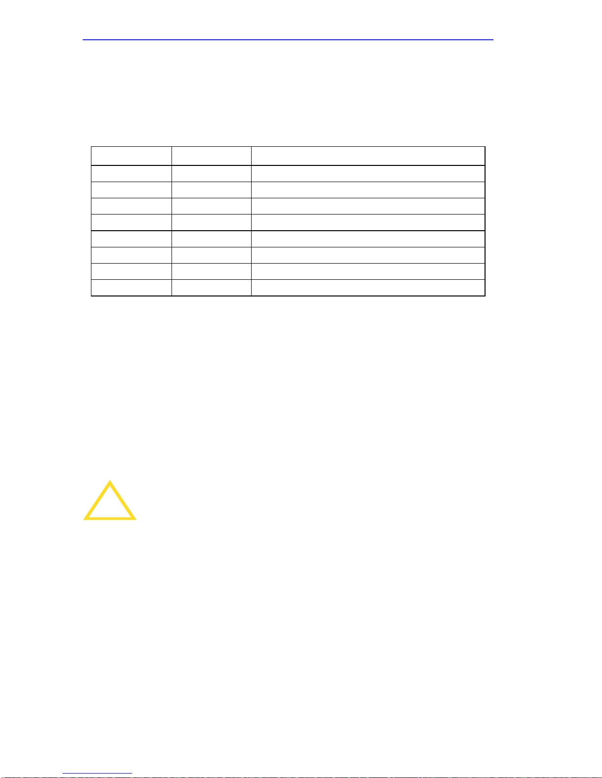
Appendix C: CSMIM2-16UG/MOD4-UG Port Upgrade Instructions
C.2.1 Contents of the Kit
Table C-1 lists the contents of the CSMIM2-16UG upgrade kit.
Table C-1 CSMIM2-16UG Upgrade Kit Contents
Item Qty. Description/Part No.
1 1 Faceplate (32 Port)
2 4 Spacer, Hex 6-32 x 3/4
3 2 Stiffener, Front Panel (32 Port)
4 1 Daughter Board
5 4 Screw, Pan Head 6-32 x 5/16
6 6 Flat Washer , 6
7 2 Screw, Pan Head 6-32 x 3/8
8 1 Label, Blank
C.2.2 Required T ools
The required tools are:
• Phillips screwdriver
C.2.3 Disassembly Instructions
The following instructions describe disassembling the CSMIM2-16.
Refer to Figure C-1 for location of screws and standoffs on CSMIM2-16.
Observe all antistatic precautions when handling electronic
!
CAUTION
1. Remove the unit from the MMAC.
2. Remove the (2) 4-40 flathead screws and (2) 6-32 screws that secure
the stiffeners to the mother board and faceplate. You may discard the
old stiffeners.
equipment.
3. Remove the (3) 6-32 faceplate mounting screws from the topside of
the MIM. Discard the old faceplate.
C-2 CSMIM2 Installation Guide
Page 81

CSMIM2-16UG Upgrade Kit
Do not misplace the screws. You will need them to secure the
NOTE
!
CAUTION
new faceplate.
Observe all antistatic precautions when handling electronic
equipment.
C.2.4 Installation Procedure
The following instructions describe how to install the 16 port daughter
card. The following steps refer to items illustrated in Figure C-1.
1. Install new faceplate (item 1) to mother board. Loosely install the (3)
6-32 mounting screws, then apply slight inward pressure on faceplate
to seat faceplate on grounding fingers and secure (3) 6-32 mounting
screws. Do not allow grounding fingers on the top and bottom of the
asynchronous port assemblies to snap through the faceplate (see
Figure C-1, View A).
2. Install (4) 6-32 x 3/4 Hex spacers (item 2) to mother board using (4)
6-32 screws and washers (items 5, 6) supplied.
3. Install daughter board (item 4) into front panel aligning RJ connectors
in faceplate openings then seating 50-pin stacking connector for final
alignment. Secure daughter board to spacers using 6-32 screws and
washers (items 5, 6) supplied. Do not allow grounding fingers on the
top and bottom of the asynchronous port assemblies to snap through
the faceplate (see Figure C-1, View A).
4. Install stiffeners (item 3) to faceplate and daughter board using
existing 4-40 flathead screws and (2) 6-32 x 3/8 screws and washers
(item 6, 7) supplied.
5. After final assembly, inspect center bar (between upper and lower
connectors) of faceplate to insure that it makes full contact with
grounding fingers of RJ connector.
6. Transfer Ethernet address and serial number on blank label (item 8)
supplied and install on front panel as shown.
CSMIM2 Installation Guide C-3
Page 82
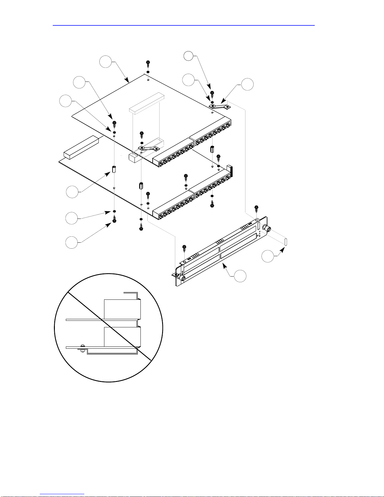
Appendix C: CSMIM2-16UG/MOD4-UG Port Upgrade Instructions
4
7
5
6
3
6
2
6
5
8
1
view A
Figure C-1 CSMIM2 32 Port Assembly
C-4 CSMIM2 Installation Guide
Page 83

CSMIM2-16UG Upgrade Kit
C.2.5 Power–up and Test
The following instructions describe the power–up and test sequence to
verify that the port upgrade was successful:
1. Reconnect all the cables.
2. Connect a terminal to the console port (port 1).
3. Plug the CSMIM2-32 into the MMAC, apply power.
4. Set CSMIM2-32 to Setup mode by pressing the Setup switch on the
front panel. The S/U indicator should light.
Press the Setup switch within 3 seconds of powering–up.
NOTE
5. The CSMIM2-32 runs its ROM–resident power–up diagnostics:
• All indicators light momentarily and then turn off.
• The Traf indicator flashes to show that diagnostics are running.
• If the diagnostics complete successfully, the Stat and Attn
indicators light. After about one minute, the ROM Monitor prompt
appears on the console terminal.
6. Issue the config command to verify the new hardware and port
configuration.
If the config command indicates that the CSMIM2 has 32 ports, then the
installation was successful.
CSMIM2 Installation Guide C-5
Page 84

Appendix C: CSMIM2-16UG/MOD4-UG Port Upgrade Instructions
C.3 MOD4-UG UPGRADE KIT
The MOD4-UG upgrade kit consists of a 4 V.32 terbo modem daughter
card and 2 MIM faceplates. This kit upgrades either the CSMIM2-16 to a
MODMIM-4 or the MODEXT-4 to a MODEXT-8. These installation
instructions provide the following:
• Kit contents
• Required tools
• Disassembly instructions
• Installation instructions
• Assembly instructions
• Power-up and test sequence
C.3.1 Contents of the MOD4-UG Kit
Table C-2 lists the contents of the MOD4-UG upgrade kit.
Table C-2 MOD4-UG Upgrade Kit Contents
Item Qty. Description/Part No.
1 2
2 4 Spacer, Hex 6-32 x 3/4
3 2 Stiffener, Front Panel (32 Port)
4 1 Daughter Board
5 4 Screw, Pan Head 6-32 x 5/16
6 9 Flat Washer
7 2 Screw, Pan Head 6-32 x 3/8
8 1 Label, Blank
9 1 EMI/RFI Shield
10 3 Spacer, M/F, 6-32 x 7/16
11 1 CSA Agency Label
12 1 FCC Identification Label
Faceplate 16 asynch. ports/4 modems
or 8 modem ports
MOD4-UG
C-6 CSMIM2 Installation Guide
Page 85

MOD4-UG Upgrade Kit
C.3.2 Required T ools
The required tools are:
• Phillips screwdriver
• 1/4" Nutdriver
C.3.3 CSMIM2-16 Disassembly Instructions
The following instructions describe disassembling the CSMIM2-16.
Refer to Figure C-1 for location of screws and standoffs on CSMIM2.
Observe all antistatic precautions when handling electronic
!
CAUTION
equipment.
1. Remove the unit from the MMAC.
2. Remove the (2) 4-40 flathead screws and (2) 6-32 screws that secure
the stiffeners to the mother board and faceplate. You may discard the
old stiffeners.
3. Remove the (3) 6-32 mounting screws from the topside of the MIM.
These hold the faceplate on. You may discard the old faceplate.
Do not misplace the screws. You will need them to secure the
NOTE
new faceplate.
C.3.4 Installation Procedure
The following instructions describe how to install the MOD4-UG
daughter card to your existing CSMIM2. The following steps refer to
items illustrated in Figure C-2.
CSMIM2 Installation Guide C-7
Page 86

Appendix C: CSMIM2-16UG/MOD4-UG Port Upgrade Instructions
7
6
5
6
4
3
9
10
5
CSMIM2
MOTHERBOARD
2
6
6
8
5
view A
Figure C-2 MODMIM-4 Assembly
1
11
12
C-8 CSMIM2 Installation Guide
Page 87

MOD4-UG Upgrade Kit
Observe all antistatic precautions when handling electronic
!
CAUTION
equipment.
1. Install the correct faceplate (item 1) to mother board. Loosely install
the (3) 6-32 M/F standoffs and washers (items 10 & 6), then apply
slight inward pressure on faceplate to seat faceplate on grounding
fingers and secure (3) 6-32 M/F standoffs. Do not allow grounding
fingers on the bottom of the asynchronous port assemblies to snap
through the faceplate (see Figure C-2, view A).
2. Install the EMI/RFI shield (item 9) to the M/F standoffs with its silver
side facing upwards, secure shield to standoffs using (3) 6-32 screws
and washers (items 5 & 6).
3. Install (4) 6-32 x 3/4 Hex spacers (item 2) to mother board using (4)
6-32 screws and washers (items 5, 6) supplied.
4. Install daughter board (item 4) into front panel aligning RJ connectors
in faceplate openings then seating 50-pin stacking connector for final
alignment. Secure daughter board to spacers using 6-32 screws and
washers (items 5, 6) supplied.
5. Install stiffeners (item 3) to faceplate and daughter board using
existing 4-40 flathead screws and (2) 6-32 x 3/8 screws and washers
(item 6, 7) supplied.
6. After final assembly, inspect faceplate to insure that it makes full
contact with grounding fingers of RJ connector.
7. Transfer Ethernet address and serial number to blank label (item 8)
supplied and install on front panel as shown.
8. Install CSA Agency Label (item 11) on front panel, with “Maple Leaf”
facing down.
9. Install FCC Identification label (item 12) on faceplate. Align its
bottom edge with the top of the green stripe located at the bottom of
the faceplate and center it as shown.
CSMIM2 Installation Guide C-9
Page 88

Appendix C: CSMIM2-16UG/MOD4-UG Port Upgrade Instructions
C.3.5 MODMIM Power–up and Test
The following instructions describe the power–up and test sequence to
verify that the modem upgrade was successful:
1. Reconnect all the cables.
2. Connect a terminal to the console port (port 1).
3. Plug the MODMIM into the MMAC, apply power.
4. Set MODMIM to Setup mode by pressing the Setup switch on the
front panel. The S/U indicator should light.
Press the Setup switch within 3 seconds of powering-up.
NOTE
5. The MODMIM runs its ROM–resident power–up diagnostics:
• All indicators light momentarily and then turn off.
• The Traf indicator flashes to show that diagnostics are running.
• If the diagnostics complete successfully, the Stat and Attn
indicators light. After about one minute, the ROM Monitor prompt
appears on the console terminal.
6. Issue the config command to verify the new hardware and port
configuration.
7. The console responds with the board configuration. Check the heading
“MODEM Config” to insure that the correct number of modem ports
were recognized (either 4 for the MODMIM-4 or 12 for the
MODEXT-8).
8. At the monitor prompt, execute the boot command.
C-10 CSMIM2 Installation Guide
Page 89

MOD4-UG Upgrade Kit
C.3.6 MODEXT-4 Disassembly Instructions
The following instructions describe disassembling the MODEXT-4.
Refer to Figure C-2 for location of screws and standoffs.
Observe all antistatic precautions when handling electronic
!
CAUTION
1. Remove the unit from the MMAC.
NOTE
equipment.
The MODEXT-4 daughter board must be removed from the
MODMIM-4 before installing the MOD4-UG upgrade. This
involves unplugging the ribbon cable from the back of the
MODEXT-4 and then carefully unsnapping the MODEXT-4 off
of the 4 nylon standoffs by applying gentle upward pressure.
2. Remove the (2) 4-40 flathead screws and (2) 6-32 screws that secure
the stiffeners to the mother board and faceplate. You may discard the
old stiffeners.
3. Remove the (3) 6-32 mounting screws from the topside of the MIM.
These hold the faceplate on. You may discard the old faceplate.
Do not misplace the screws. You will need them to secure the
NOTE
new faceplate.
C.3.7 Installation Procedure
The following instructions describe how to install the MOD4-UG
daughter card to your existing MODEXT-4. The following steps refer to
items illustrated in Figure C-3.
Observe all antistatic precautions when handling electronic
!
CAUTION
equipment.
CSMIM2 Installation Guide C-11
Page 90

Appendix C: CSMIM2-16UG/MOD4-UG Port Upgrade Instructions
1. Install the correct faceplate (item 1) to mother board. Loosely install
the (3) 6-32 mounting screws, then apply slight inward pressure on
faceplate to seat faceplate and secure (3) 6-32 mounting screws.
2. Install (4) 6-32 x 3/4 Hex spacers (item 2) to mother board using (4)
6-32 screws and washers (items 5, 6) supplied.
3. Install daughter board (item 4) into front panel aligning RJ connectors
in faceplate openings then seating 50-pin stacking connector for final
alignment. Secure daughter board to spacers using 6-32 screws and
washers (items 5, 6) supplied.
4. Install stiffeners (item 3) to faceplate and daughter board using
existing 4-40 flathead screws and (2) 6-32 x 3/8 screws and washers
(item 6, 7) supplied.
5. After final assembly, inspect faceplate to insure that it makes full
contact with grounding fingers of RJ connectors.
6. Transfer Revision and serial number to blank label (item 8) supplied
and install on front panel as shown.
C-12 CSMIM2 Installation Guide
Page 91
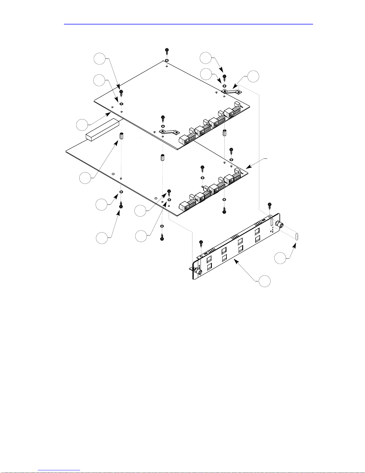
MOD4-UG Upgrade Kit
5
6
7
6
3
4
MODEXT-4
MOTHERBOARD
2
6
5
5
6
8
1
Figure C-3 MODEXT-4 Assembly
C.3.8 MODEXT-8 Power–up and Test
The following instructions describe the power–up and test sequence to
verify that the modem was successfully upgraded to a MODEXT-8.
1. Reconnect all the cables.
2. Connect a terminal to the console port (port 1).
3. Plug the MODMIM into the MMAC, apply power.
CSMIM2 Installation Guide C-13
Page 92

Appendix C: CSMIM2-16UG/MOD4-UG Port Upgrade Instructions
4. Set MODMIM to Setup mode by pressing the Setup switch on the
front panel. The S/U indicator should light.
Press the Setup switch within 3 seconds of powering-up.
NOTE
5. The MODMIM runs its ROM–resident power–up diagnostics:
• All indicators light momentarily and then turn off.
• The Traf indicator flashes to show that diagnostics are running.
• If the diagnostics complete successfully, the Stat and Attn
indicators light. After about one minute, the ROM Monitor prompt
appears on the console terminal.
6. Issue the config command to verify the new hardware and port
configuration.
7. The console responds with the board configuration. Check the heading
“MODEM Config” to insure that the correct number of modem ports
were recognized (12).
8. At the monitor prompt, execute the boot command.
C-14 CSMIM2 Installation Guide
Page 93

APPENDIX D
MODEXT-4/MODEXT-8
MODEM UPGRADE INSTRUCTIONS
D.1 GENERAL
This appendix provides instructions on upgrading your MODMIM-4 by
adding either 4 internal modems with the MODEXT-4 upgrade kit or 8
internal modems with the MODEXT-8 upgrade kit. These installation
instructions provide the following:
• Kit contents
• Required tools
• Installation instructions
D.2 CONTENTS OF THE KIT
Table D-1 lists the contents of the Modem upgrade kit.
Table D-1 Modem Upgrade Kit Contents
Item Qty. Description/Part No.
1 1 4 or 8 port Modem Module Assy
2 4 Standoff, 1-1/8", nylon
3 1 Handle, black, 3"
4 2 Screw, phillips, 6-32 x 1/4
5 1 Disposable wrist strap
D.3 REQUIRED TOOLS
The required tools are:
• Phillips screwdriver
CSMIM2 Installation Guide D-1
Page 94

Appendix D: MODEXT-4/MODEXT-8 Modem Upgrade Instructions
D.4 INSTALLATION PROCEDURE
To install the Modem Module:
1. Attach the black handle (item 3) to the MODMIM-4 module by poking
two (2) holes through the front panel label from the outside of the
handle mounting holes (Figure D-1). The mounting holes are clearly
visible from the back of the front panel. Hold the MODMIM-4 up to
the light, allowing the light to shine through the lexan label from the
front. Poke the two holes through the lexan using the point of your
phillips head screwdriver. Install the two (2) phillips head screws and
tighten.
2. Install the four (4) 1-1/8" threaded nylon standoffs (item 2) into the
four threaded inserts in the MODEXT module and tighten by hand.
3. Install the ribbon cable connector of the MODEXT module into
connector J9 located at the rear of the MODMIM module.
4. Align the four nylon standoffs on the MODEXT module with their
mating holes in the MODMIM-4 module and snap together insuring
that the front panel retaining tabs are aligned and fully seated.
5. Re-install the module into MMAC hub and power up.
Observe all antistatic precautions when handling electronic
!
CAUTION
equipment.
D.5 MODMIM POWER–UP AND TEST
The following instructions describe the power–up and test sequence to
verify that the modem upgrade was successful:
1. Reconnect all the cables.
2. Connect a terminal to the console port (port 1).
3. Plug the MODMIM into the MMAC, apply power.
4. Set MODMIM to Setup mode by pressing the Setup switch on the
front panel. The S/U indicator should light.
D-2 CSMIM2 Installation Guide
Page 95

MODMIM Power–up and Test
Press the Setup switch within 3 seconds of powering–up.
NOTE
5. The MODMIM runs its ROM–resident power–up diagnostics:
• All indicators light momentarily and then turn off.
• The Traf indicator flashes to show that diagnostics are running.
• If the diagnostics complete successfully, the Stat and Attn
indicators light. After about one minute, the ROM Monitor prompt
appears on the console terminal.
6. Issue the config command to verify the new hardware and port
configuration.
7. The console responds with the board configuration. Check the heading
“MODEM Config” to insure that the correct number of modem ports
were recognized (either 8 for the MODEXT-4 or 12 for the
MODEXT-8).
8. At the monitor prompt, execute the boot command.
CSMIM2 Installation Guide D-3
Page 96
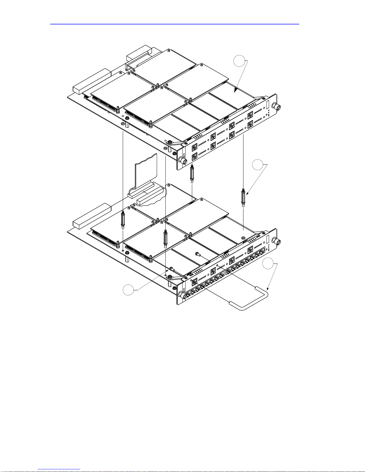
Appendix D: MODEXT-4/MODEXT-8 Modem Upgrade Instructions
1
2
4
Figure D-1 MODEXT Modem Upgrade Kit
3
D-4 CSMIM2 Installation Guide
Page 97

INDEX
A
addr command 3-3
examples 3-4
Approvals
Agency 1-8
B
boot command 3-6
examples 3-10
boot error report 4-7
field descriptions 4-7
boot failures
correcting boot parameters 4-9
error report 4-7
file server hosts not responding
CSMIM 4-12
over SLIP 4-11
UNIX 4-10
troubleshooting procedures 4-6
boot -l command 3-9
booting
sequence 4-1
BOOTP 2-10
broadcast address
setting 3-5
C
Cables
maximum lengths 2-7
cables and connectors B-1
config command 3-11
Connecting CSMIM
to console 2-7
to serial devices 2-7
Console Port A-1
Console port
description of 1-7, 1-9
pin/signal allocations A-1
console port 1-7, 1-9, 2-7
Console terminal
description 2-7
console-baud command 3-11
D
dumps 4-12
files 4-12
E
environmental requirements 1-8
erase command 3-13
Ethernet
transceiver loopback test 3-17
Ethernet address
displaying 3-3
during power-up 2-9
Insert BookTitle Index-1
F
FCC Notice ii
front panel
description of 1-9
H
hardware configuration
displaying 3-11
during power-up 2-9
help command 3-14
Page 98

Index
I
IC Notice iv
image command 3-14, 3-15
examples 3-14, 3-15, 3-16, 3-17,
3-18
image -d command 3-16
image name
default 3-6, 3-14
indicator states
during a dump 4-13
error-free normal mode 4-2
error-free test mode 4-4
normal mode error states 4-3
test mode error states 4-5
Industry Canada Certification
Number iii
initial boot parameters
setting addresses 3-3
Installation ?? to 2-6
installation
instructions 2-1
Internet address
setting 3-5
IP encapsulation
setting 3-5
L
lat -d command 3-16
lat_key command 3-16
Load Number iii
load/dump gateway
setting 3-5
M
manual booting
description 3-6
mop command 3-17
mop -d command 3-17
N
net command 3-17
normal mode
error indicator states 4-3
error-free indicator states 4-2
error-free sequence 4-2
power-up and booting sequence 4-2
power-up error states 4-3
O
option_key command 3-18
option_key -d command 3-18
P
physical characteristics
description of 1-8
ping command 3-18
port pin/signal allocations A-1
port upgrade
instructions C-1, D-1
ports command 3-19
power-up
applying power 2-8
failures during 2-8
in normal mode 4-2
in test mode 4-4
instructions 2-8
running self-tests 2-8
self-testing procedures during 2-8
sequence 4-1
setting to test mode 2-8
power-up and boot sequence 4-1
preferred load host
setting 3-5
R
RARP 2-10
ROM Monitor
command syntax 3-1
commands 3-1
description of 1-4
list of commands 3-1
Index-2 Insert BookTitle
Page 99

Index
S
sequence command 3-21
examples 3-21
Serial Devices 2-7
setting
boot sequence 3-21
broadcast address 3-5
Internet address 3-5
IP encapsulation 3-5
load/dump gateway address 3-5
preferred load host address 3-5
SLIP parameters 3-23
subnet mask 3-5
size 1-8
SLIP
parameters 3-23
slip command 3-23
example 3-24
software installation
executing boot command 2-12
procedures 2-12
setting boot sequence 2-12
setting initial boot parameters 2-12
setting Internet address 2-12
setting SLIP parameters 2-12
stats command 3-25
example 3-25
status indicators
description of 1-7, 1-9
subnet mask
setting 3-5
System Description 1-4
T
test
Ethernet transceiver loopback 3-17
printer port 3-19
serial line ports 3-19
Test Mode 4-4
test mode
entering 4-4
entering during power-up 2-8
error indicator states 4-5
error-free indicator states 4-4
error-free power-up sequence 4-4
power-up and booting sequence 4-4
power-up error states 4-5
Test switch 1-6, 1-9, 1-10
description of 1-9, 1-10
TFTP 3-8
troubleshooting
during power-up and booting 4-1
procedures 4-1
U
Unpacking 2-1
Upgrades
Modem 1-5
Insert BookTitle Index-3
Page 100

Index
Index-4 Insert BookTitle
 Loading...