

Page 1

CRBRIM-W/E
USER’S GUIDE
Page 2

NOTICE
Cabletron Systems reserves the right to make changes in specifications and other
information contained in this document without prior notice. The reader should in all cases
consult Cabletron Systems to determine whether any such changes have been made.
The hardware, firmware, or software described in this manual is subject to change without
notice.
IN NO EVENT SHALL CABLETRON SYSTEMS BE LIABLE FOR ANY
INCIDENTAL, INDIRECT, SPECIAL, OR CONSEQUENTIAL DAMAGES
WHATSOEVER (INCLUDING BUT NOT LIMITED TO LOST PROFITS) ARISING
OUT OF OR RELATED TO THIS MANUAL OR THE INFORMATION CONTAINED
IN IT, EVEN IF CABLETRON SYSTEMS HAS BEEN ADVISED OF, KNOWN, OR
SHOULD HAVE KNOWN, THE POSSIBILITY OF SUCH DAMAGES.
© Copyright October 1994 by:
Cabletron Systems, Inc.
P.O. Box 5005
Rochester, NH 03866-5005
All Rights Reserved
Printed in the United States of America
Part Number: 9031246 October 1994
SPECTRUM
EMME, EMM-E6, ESXMIM, MMAC-8FNB, MMAC-5FNB
MicroMMAC, NBR-420/620
Ethernet
VT-220
CompuServe
and
LANVIEW
is a registered trademark of Xerox Corp.
and
VT-320
are trademarks of Digital Equipment Corp.
is a registered trademark of CompuServe, Inc.
are registered trademarks and
, and
EPIM
are trademarks of Cabletron Systems, Inc.
CRBRIM-W/E, EPIM-3PS,
Printed on
recycled paper.
, and
MMAC-3FNB
,
Hardware User’s Guide
Hardware Installation Guide
i
-i
Page 3

Notice
FCC NOTICE
This device complies with Part 15 of the FCC rules. Operation is subject to the following
two conditions: (1) this device may not cause harmful interference, and (2) this de vice must
accept any interference received, including interference that may cause undesired
operation.
NOTE:
digital device, pursuant to Part 15 of the FCC rules. These limits are designed to provide
reasonable protection against harmful interference when the equipment is operated in a
commercial environment. This equipment uses, generates, and can radiate radio frequency
energy and if not installed in accordance with the operator’s manual, may cause harmful
interference to radio communications. Operation of this equipment in a residential area is
likely to cause interference in which case the user will be required to correct the
interference at his own expense.
WARNING:
approved by the party responsible for compliance could void the user’s authority to operate
the equipment.
This equipment has been tested and found to comply with the limits for a Class A
Changes or modifications made to this device which are not expressly
DOC NOTICE
This digital apparatus does not exceed the Class A limits for radio noise emissions from
digital apparatus set out in the Radio Interference Regulations of the Canadian Department
of Communications.
Le présent appareil numérique n’émet pas de bruits radioélectriques dépassant les limites
applicables aux appareils numériques de la class A prescrites dans le Règlement sur le
brouillage radioélectrique édicté par le ministère des Communications du Canada.
ii
CRBRIM-W/E
Page 4

CABLETRON SYSTEMS, INC.
PROGRAM LICENSE AGREEMENT
Notice
IMPORTANT:
This document is an agreement between you, the end user, and Cabletron Systems, Inc.
(“Cabletron”) that sets forth your rights and obligations with respect to the Cabletron
software program (the “Program”) contained in this package. The Program may be
contained in firmware, chips or other media. BY UTILIZING THE ENCLOSED
PRODUCT, YOU ARE AGREEING TO BECOME BOUND BY THE TERMS OF THIS
AGREEMENT, WHICH INCLUDES THE LICENSE AND THE LIMITATION OF
WARRANTY AND DISCLAIMER OF LIABILITY. IF YOU DO NOT AGREE TO THE
TERMS OF THIS AGREEMENT , PROMPTL Y RETURN THE UNUSED PRODUCT TO
THE PLACE OF PURCHASE FOR A FULL REFUND.
Before utilizing this product, carefully read this License Agreement.
CABLETRON SOFTWARE PROGRAM LICENSE
1. LICENSE.
in this package subject to the terms and conditions of this License Agreement.
You have the right to use only the one (1) copy of the Program pro vided
You may not copy, reproduce or transmit any part of the Program except as permitted
by the Copyright Act of the United States or as authorized in writing by Cabletron.
2. O
disassemble the Program.
3. APPLICABLE LA
under the laws and in the state and federal courts of New Hampshire. You accept the
personal jurisdiction and venue of the New Hampshire courts.
THER RESTRICTIONS. You may not reverse engineer, decompile, or
W. This License Agreement shall be interpreted and governed
Hardware User’s Guide
Hardware Installation Guide
iii
iii
Page 5

Notice
EXCLUSION OF WARRANTY
AND DISCLAIMER OF LIABILITY
1. EXCLUSION OF
Cabletron in writing, Cabletron makes no warranty, expressed or implied, concerning the
Program (including Its documentation and media).
CABLETRON DISCLAIMS ALL WARRANTIES, OTHER THAN THOSE
SUPPLIED TO YOU BY CABLETRON IN WRITING, EITHER EXPRESS OR
IMPLIED, INCLUDING BUT NOT LIMITED TO IMPLIED WARRANTIES OF
MERCHANTABLITY AND FITNESS FOR A PARTICULAR PURPOSE, WITH
RESPECT TO THE PROGRAM, THE ACCOMPANYING WRITTEN MATERIALS,
AND ANY ACCOMPANYING HARDWARE.
2. NO LIABILITY FOR CONSEQ
CABLETRON OR ITS SUPPLIERS BE LIABLE FOR ANY DAMAGES
WHATSOEVER (INCLUDING, WITHOUT LIMITATION, DAMAGES FOR LOSS OF
BUSINESS, PROFITS, BUSINESS INTERRUPTION, LOSS OF BUSINESS
INFORMATION, SPECIAL, INCIDENTAL, CONSEQUENTIAL, OR RELIANCE
DAMAGES, OR OTHER LOSS) ARISING OUT OF THE USE OR INABILITY TO USE
THIS CABLETRON PRODUCT, EVEN IF CABLETRON HAS BEEN ADVISED OF
THE POSSIBILITY OF SUCH DAMAGES. BECAUSE SOME STATES DO NOT
ALLOW THE EXCLUSION OR LIMITATION OF LIABILITY FOR
CONSEQUENTIAL OR INCIDENTAL DAMAGES, OR ON THE DURATION OR
LIMITATION OF IMPLIED WARRANTEES IN SOME INSTANCES THE ABOVE
LIMITATIONS AND EXCLUSIONS MAY NOT APPLY TO YOU.
WARRANTY. Except as may be specifically provided by
UENTIAL DAMAGES. IN NO EVENT SHALL
UNITED STATES GOVERNMENT RESTRICTED RIGHTS
The enclosed product (a) was developed solely at private expense; (b) contains “restricted
computer software” submitted with restricted rights in accordance with Section 52227-19
(a) through (d) of the Commercial Computer Software - Restricted Rights Clause and its
successors, and (c) in all respects is proprietary data belonging to Cabletron and/or its
suppliers.
For Department of Defense units, the product is licensed with “Restricted Rights” as
defined in the DoD Supplement to the Federal Acquisition Regulations, Section 52.2277013 (c) (1) (ii) and its successors, and use, duplication, disclosure by the Government is
subject to restrictions as set forth in subparagraph (c) (1) (ii) of the Rights in T echnical Data
and Computer Software clause at 252.227-7013. Cabletron Systems, Inc., 35 Industrial
Way, Rochester, New Hampshire 03867.
iv
CRBRIM-W/E
Page 6

Contents
Chapter 1 Introduction
1.1 Using This Manual............................................................................1-2
1.2 Document Objectives.......................................................................1-2
1.3 Document Organization....................................................................1-2
1.4 Document Conventions....................................................................1-3
1.5 Related Manuals .............................................................................. 1-5
1.6 Getting Help ..................................................................................... 1-5
Chapter 2 Product Overview
2.1 System Specifications......................................................................2-2
2.2 Memory Configurations....................................................................2-3
Chapter 3 Preparing for Installation
3.1 Preventing Electrostatic Discharge Damage....................................3-1
3.2 System Operation Prerequisites.......................................................3-2
3.3 Distance Limitations.........................................................................3-2
3.3.1 Serial Connections............................................................3-2
3.4 Interference Considerations.............................................................3-4
3.5 Console Considerations...................................................................3-5
3.5.1 Console Port Connections................................................3-5
3.6 Network Connection Considerations................................................3-6
3.6.1 Ethernet Connections.......................................................3-6
3.6.2 Serial Connections............................................................3-6
3.7 Inspecting the System......................................................................3-7
Hardware User’s Guide
Hardware Installation Guide
-v
v
Page 7

Contents
Chapter 4 Installation
4.1 Tools and Parts Required.................................................................4-1
4.2 Installing the CRBRIM-W/E.............................................................. 4-2
4.2.1 Installing a CRBRIM-W/E into a MIM................................4-3
4.2.2 Installing the EPIM-3PS....................................................4-4
4.2.3 Connecting the CRBRIM-W/E to the EPIM-3PS...............4-5
4.3 Making External Connections...........................................................4-6
Chapter 5 Troubleshooting the Hardware
Configuration
5.1 Problem Solving............................................................................... 5-2
5.1.1 Troubleshooting the Network Interfaces and Cables........5-2
5.1.2 Reading LED Indicators....................................................5-3
Chapter 6 Maintenance
6.1 Installing Primary-Memory DRAM SIMMs........................................6-1
6.1.1 Tools and Equipment Required........................................ 6-2
6.1.2 Primary Memory Configurations.......................................6-2
6.1.3 Approved DRAM SIMMs...................................................6-3
6.1.4 DRAM SIMM Installation...................................................6-3
6.2 Replacing System-Code SIMMs ...................................................... 6-5
6.2.1 Tools and Equipment Required........................................ 6-5
6.2.2 System-Code SIMM Replacement ................................... 6-5
6.3 Recovering a Lost Password............................................................6-7
Appendix A Cabling Specifications
Console Port Signals and Pinouts.........................................................A-2
Serial Cable Assemblies and Pinouts.....................................................A-3
EIA-530......................................................................................A-3
RS-232.......................................................................................A-5
RS-449.......................................................................................A-8
V.35 ........................................................................................A-11
X.21 ........................................................................................A-14
vi
CRBRIM-W/E
Page 8

Contents
Appendix B Virtual Configuration Register
Virtual Configuration Register Settings...................................................B-1
Changing Configuration Register Settings.................................B-3
Virtual Configuration Register Bit Meanings..............................B-4
Enabling Booting from Flash......................................................B-8
Copying to Flash........................................................................B-8
Appendix C Bootstrap Program
Entering the Bootstrap Program.............................................................C-1
Available Bootstrap Commands.................................................C-2
Running the Diagnostics............................................................C-5
Hardware User’s Guide
Hardware Installation Guide
vii
vii
Page 9
Chapter 1
Introduction
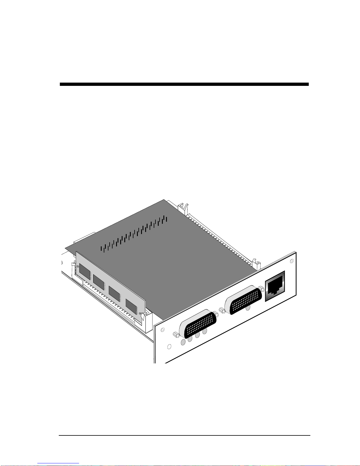
Welcome to the Cabletron Systems CRBRIM-W/E User’s Guide. This manual
describes features, explains installation procedures, and provides specifications for
the Cabletron Systems CRBRIM-W/E. The CRBRIM-W/E is designed to reside
in, and provide additional connectivity/functionality to, various Cabletron MIMs
and hubs (e.g., the EMM-E6, ESXMIM, NBR-420/620 or MicroMMAC).
Figure 1-1. CRBRIM-W/E
Hardware User’s Guide
S0
S1
SYS S1
LANPWR
RESET
Hardware Installation Guide
CONSOLE
TP
S0
1-1
1-1
Page 10

CHAPTER 1: Introduction
1.1 Using This Manual
Read through this manual completely to familiarize yourself with its content and
to gain an understanding of the features and capabilities of the CRBRIM-W/E. A
general working knowledge of data communications networks and their physical
layer components is helpful when using the CRBRIM-W/E.
1.2 Document Objectives
This publication will step you through initial site preparation, installation, and
troubleshooting. It also covers selected maintenance procedures.
1.3 Document Organization
The major sections of this publication follow:
• Chapter 1, “Introduction” outlines the contents, and describes the objectives
and conventions of the
chapter also provides a list of related manuals and
information.
• Chapter 2, “Product Overview, ” contains an o v erview of the router feature set
and physical specifications.
• Chapter 3, “Preparing for Installation, ” includes safety recommendations, site
requirements, an installation checklist, console and auxiliary port cable
connection considerations, network connection considerations, and
instructions for inspecting the new system.
• Chapter 4, “Installation,” provides a list of tools and parts required,
procedures for making external connections, and information about what to
do after installing the hardware.
• Chapter 5, “Troubleshooting the Hardware Configuration,” briefly discusses
troubleshooting, problem solving, and reading LED indicators.
• Chapter 6, “Maintenance,” includes procedures for upgrading system code
SIMMs, replacing DRAM SIMMs, and recovering from a lost password.
CRBRIM-W/E Hardware Installation Guide
GETTING HELP
. This
1-2
CRBRIM-W/E
Page 11

Document Conventions
• Appendix A, “Cabling Specifications,” provides cable illustrations and
pinouts for the console port and serial cables.
• Appendix B, “Virtual Configuration Register,” discusses the settings for and
functions of the virtual configuration register.
• Appendix C, “Bootstrap Program,” contains procedures for testing system
memory and the central processor unit (CPU) by using the bootstrap
diagnostic tests and command options.
1.4 Document Conventions
This publication uses the following conventions to convey instructions and
information:
Command descriptions use these conventions:
• Commands and keywords are in
• Variables for which you supply values are in
boldface
font.
italic
font.
• Elements in square brackets ([ ]) are optional.
• Alternative but required keywords are grouped in braces ({ }) and are
separated by a vertical bar ( | ).
Examples use these conventions:
• Terminal sessions are in
• Information you enter is in
screen
font.
boldface screen
font.
• Nonprinting characters are shown in angle brackets (< >).
• Information the system displays is in
screen
font, with default responses in
square brackets ([ ]).
Hardware User’s Guide
Hardware Installation Guide
1-3
3
Page 12

CHAPTER 1: Introduction
Means reader take note. Notes contain helpful suggestions or
NOTE
references to materials not contained in this manual.
Means the described action saves time. You can save time by
TIP
performing the action described in the paragraph.
Means reader be careful. You are capable of doing something that
might result in equipment damage or loss of data.
!
CAUTION
WARNING
Means danger. You are in a situation that could cause bodily
injury . Befor e you work on any equipment, be awar e of the hazards
involved with electrical circuitry and standard practices for
preventing accidents.
1-4
CRBRIM-W/E
Page 13

Related Manuals
1.5 Related Manuals
Use the following manuals to supplement the procedures and data provided in this
manual. This manual references procedures in these manuals, when appropriate,
but does not repeat them.
Cabletron Systems’
Cabletron Systems’
Cabletron Systems’
Cabletron Systems’
Cabletron Systems’
Cabletron Systems’
Cabletron Systems’
Cabletron System’s
(A compilation of Cisco Systems® Router Products Configuration
and Reference Guides)
EMM-E6 Installation Guide
EMM-E6 Local Management Guide
ESXMIM User’s Guide
ESXMIM Local Management Guide
MicroMMAC User’s Guide
NBR-620/420/220 User’s Guide
NBR-620/420/220 Local Management Guide
CRM-DOC
Set
1.6 Getting Help
If you need additional support related to the Cabletron Systems CRBRIM-W/E, or
if you have any questions or comments related to this manual, contact Cabletron
Systems Technical Support by:
Mail: Cabletron Systems, Inc.,
P.O. Box 5005
Rochester, NH 03866-5005
Phone: (603) 332-9400, Mon-Fri 8AM to 8PM EST
CompuServe®: GO CTRON from any ! prompt
Internet Mail: support@ctron.ctron.com
Hardware User’s Guide
Hardware Installation Guide
1-5
5
Page 14
Chapter 2
Product Overview
Bridge/Router Interface Modules (BRIMs) reside in, and provide additional
connectivity/functionality to, various Cabletron MIMs and hubs (e.g. the EMME6 or MicroMMAC). Cabletron’s CRBRIM-W/E remote access router provides
multi-protocol router capability for Cabletron MMAC (Multi-Media Access
Center) modules with BRIM and EPIM (Ethernet Port Interface Module) slots.
The CRBRIM-W/E utilizes a fixed configuration of two WAN ports, and one
internal Ethernet port. The two high density WAN ports support V.35, X.21,
RS449, RS422, RS530, and RS232 interfaces. The CRBRIM-W/E uses Cisco
Systems ® routing software and is capable of supporting Frame Relay , X.25, DDN
X.25, SMDS, T1/E1, and DDS circuit connections.
The CRBRIM-W/E uses a FLASH EEPROM and is shipped with system code
operating from Flash memory by default. (For more information on system-code
operation, see Chapter 3, section 3.2 “System Operation Prerequisites.”)
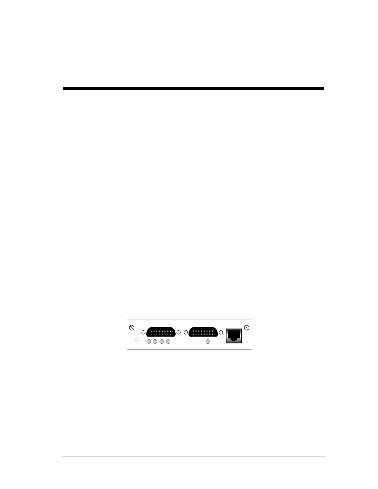
Figure 2-1 shows a front view of the CRBRIM-W/E.
RESET
S1 S0
LANPWR SYS
S1
S0
CONSOLE
Figure 2-1. CRBRIM-W/E
Sections of this chapter follow:
• System Specifications
• Memory Configurations
• Protocol Support
Hardware User’s Guide
Hardware Installation Guide
2-1
2-1
Page 15

CHAPTER 2: Product Overview
This publication takes you through the initial har dwar e installation
NOTE
and selected maintenance procedures. Refer to your specific MIM
or Management Module Installation Guides and Local
Management Guides for software configuration and operating
information.
2.1 System Specifications
System specifications of the CRBRIM-W/E are listed in Table 2-1.
Table 2-1. System Specifications
Description Design Specification
Dimensions H x W x D 3x12.5x15.5cm
Current
Power dissipation
Processor 20-MHz Motorola 68EC030
Network interface 1 Ethernet and 2 synchronous serial (2501)
Ethernet interface (internal) IEEE 802.3 (CRBRIM to EPIM-3PS)
Synchronous serial
interfaces
Console ports Asynchronous serial (RJ-45)
Operating environment 32 through 104°F (0 through 40°C)
Nonoperating temperature –40 through 185°F (–40 through 85°C)
1.0 to 0.5 amps (A)
40W (max.), 135.5 British thermal units (Btu)/hr
RS-232, RS-449, V.35, X.21 (NRZ/NRZI
DTE/DCE
EIA-530 (NRZ/NRZI and DTE mode)
All serial interfaces use the DB-60 connector at
the chassis.
2
mode)
1
and
Operating humidity 5 through 95%, noncondensing
Noise level 34 dBa @ 3' (0.914 m)
1. NRZ = Nonreturn to zero. NRZI = Nonreturn to zero inverted.
2. DTE = Data terminal equipment. DCE = Data communications equipment.
2-2
CRBRIM-W/E
Page 16

Memory Configurations
2.2 Memory Configurations
The CRBRIM-W/E has the following memory systems:
• Primary memory (main memory)—Dynamic random-access memory
(DRAM) that stores the running configuration and routing tables; mounted on
the system card.
• Shared memory—Shared DRAM that is used for packet buffering by the
router network interfaces.
• System-code memory—Flash or programmable read-only memory (PROM);
stores the operating system software image.
• Boot ROM memory—Stores a subset of the operating system software image
that is called the system bootstrap image or the bootstrap program (or ROM
monitor). The system bootstrap image allows you to boot the router when
Flash memory does not contain a valid system image.
The boot ROM prompt follo ws: Router(boot)>. The bootstrap program (R OM
monitor) prompt is the greater than sign (>), which dif fers from the user-le vel
operating-system prompt of gateway >. (For more information, see Appendix
B, “Virtual Configuration Register,” and Appendix C, “Bootstrap Program.”
• Nonvolatile random-access memory (NVRAM)—Stores the system
configuration file and the virtual configuration register.
Hardware User’s Guide
Hardware Installation Guide
2-3
3
Page 17

CHAPTER 2: Product Overview
Table 2-2 shows possible memory configurations for the CRBRIM-W/E.
Table 2-2. Memory Configurations
Memory Type Memory Capacity
Primary memory (DRAM SIMMs) 1 MB (expandable to 4 or 16 MB)
Shared (packet) memory 1 MB (DRAM on board)
System-code memory (Flash or
PROMs)
Boot ROM 1 MB
Nonvolatile RAM (NVRAM) 32 KB
1. The router has 2 MB of permanent (fixed) DRAM memory and a DRAM SIMM
socket for upgrading the memory. 1 MB of this permanent memory is used by the
CPU and is called
work interface ports to store packets and is called
a DRAM SIMM is installed in the DRAM SIMM socket, all of the DRAM memory on
this SIMM becomes primary memory for the CPU, and the 2 MB of DRAM that is
permanent on the board becomes shared memory.
primary
memory. The other 1 MB of memory is used by the net-
4 MB (expandable)
shared
or
packet
1
memory. When
2.3 Protocol Support
The CRBRIM-W/E is hardware encoded at the factory to operate with one of three
router software sets. This provides users with the option of selecting IP,
DESKTOP, or ENTERPRISE routing software at the time of purchase.
The CRBRIM-W/E is factory configured for either IP, DESKTOP
NOTE
or ENTERPRISE Routing Softwar e. The factory har dware settings
are permanent and cannot be changed to operate a differ ent r outer
software set.
2-4
CRBRIM-W/E
Page 18

Protocol Support
The ENTERPRISE router software set provides all Cisco-supported LAN, WAN,
and routing protocols as well as IBM features and protocol translator functionality .
Supported LAN protocols include IP, Novell, IPX, DECnet IV, AppleTalk Phase 1
and 2, bridging, DECnet V, XNS, Banyon VINES, OSI, Apollo Domain, PUP, and
CHA OSnet.
The DESKTOP software set supports IP, Novell, IPX, DECnet IV, AppleTalk
Phase 1 and 2, and bridging.
The IP software set supports IP, and bridging protocols.
CRBRIM-W/E models configured for either DESKTOP or
NOTE
ENTERPRISE Routing Software are shipped with a user
installable 4 megabyte primary memory DRAM SIMM. See
Chapter 6, section 6.1.4 DRAM SIMM Installation for installation
procedur es.
All CRBRIM-W/E models are shipped with Frame Relay and X.25 software that
offers efficient remote site access to packet switched networks.
Hardware User’s Guide
Hardware Installation Guide
2-5
5
Page 19

Chapter 3
Preparing for Installation
This chapter describes the tasks you must perform before starting actual system
installation.
Sections of this chapter follow:
• Preventing Electrostatic Discharge Damage
• System Operation Prerequisites
• Distance Limitations
• Interference Considerations
• Console Considerations
• Network Connection Considerations
• Inspecting the System
3.1 Preventing Electrostatic Discharge Damage
Electrostatic discharge (ESD) damages equipment and impairs electrical circuitry.
It occurs when electronic components are improperly handled and causes
complete or intermittent failures.
Follow ESD-pre vention procedures when handling electronic components. Ensure
that the chassis is electrically connected to earth ground. Wear an ESD wrist strap,
ensuring that it makes good skin contact. Connect the clip to an unpainted chassis
frame surface to safely channel unwanted ESD voltages to ground. To properly
guard against ESD damage and shocks, the wrist strap and cord must operate
effectively. If no wrist strap is available, ground yourself by touching the metal
part of the chassis.
Hardware User’s Guide
Hardware Installation Guide
3-1
3-1
Page 20

CHAPTER 3: Preparing for Installation
For safety, periodically check the resistance value of the antistatic
strap, which should be within the range of 1 and 10 MΩ.
!
CAUTION
3.2 System Operation Prerequisites
The CRBRIM-W/E is designed to run system code from Flash memory single inline memory modules (SIMMs). With the proper system code image, the router
also can be run from dynamic random-access memory (DRAM); however, this
operation requires a 4-MB memory upgrade (installation of a 4 MB x 72 pin
DRAM SIMM). Further, operating system code from DRAM can result in a 25percent decrease in system performance.
Operating the system code from Flash is the default and is recommended for
optimum performance of the router.
3.3 Distance Limitations
When setting up your router, consider distance limitations and potential
electromagnetic interference (EMI) as defined by the Electronic Industries
Association (EIA). Following are the distance limitation specifications for serial
interfaces.
3.3.1 Serial Connections
As with all signaling systems, RS-232 signals travel a limited distance at any
given bit rate; generally, the slower the data rate, the greater the distance.
Table 3-1 shows the standard relationship between baud rate and maximum
distance.
3-2
CRBRIM-W/E
Page 21

Distance Limitations
Table 3-1. IEEE Standard RS-232 Transmission Speed Versus Distance
!
CAUTION
Baud Rate
2400 200 60
4800 100 30
9600 50 15
19200 25 7.6
38400 12 3.7
Distance
(Feet)
Distance
(Meters)
RS-232 is often used in violation of these specifications. If you
understand the electrical problems that can arise and can
compensate for them, you might be able to get good results at
distances greater than those shown in Table 3-1; however, do so at
your own risk. We recommend that you stay within the standarddefined distance.
Balanced drivers allow RS-449 signals to travel greater distances than RS-232.
Table 3-2 lists the standard relationship between baud rate and maximum distance
for RS-449 signals. These limits are also valid for V.35 and X.21.
Hardware User’s Guide
Hardware Installation Guide
3-3
3
Page 22

CHAPTER 3: Preparing for Installation
Table 3-2. IEEE Standard RS-449 Transmission Speed Versus Distance
!
CAUTION
Baud
Rate
2400 4100 1250
4800 2050 625
9600 1025 312
19200 513 156
38400 256 78
56000 102 31
T1 50 15
Distance
(Feet)
Distance
(Meters)
The RS-449 and V.35 interfaces support data rates up to 2.048
Mbps. Exceeding this maximum is not recommended; do so at your
own risk.
3.4 Interference Considerations
When you run cables for any significant distance in an electromagnetic field,
interference can occur between the field and the signals on the cables. This fact
has two implications for the construction of terminal plant cabling:
• Plant cabling can emanate radio interference if it is unshielded for too long a
distance.
• Strong electromagnetic interference (EMI) (e.g. lightning or radio
transmitters) can destroy the RS-232 drivers and receivers in the server.
If you use twisted-pair cables with a good distribution of grounding conductors in
your plant cabling, emitted radio interference is unlikely. If you exceed the
maximum distances, ground the conductor for each data signal; however, this
practice is not recommended.
3-4
CRBRIM-W/E
Page 23

Console Considerations
If you have cables exceeding recommended distances, or if you have cables that
pass between buildings, giv e special consideration to the ef fect of lightning strikes
or ground loops. The electromagnetic pulse caused by lightning or other highenergy phenomena can easily couple enough energy into unshielded conductors to
destroy electronic devices. If your site has experienced problems of this sort,
consult experts in lightning suppression and shielding.
Most data centers cannot resolve the infrequent, but potentially catastrophic
problems just described without pulse meters and other special equipment. Take
precautions to avoid these problems by providing a properly grounded and
shielded environment, with special attention to issues of electrical surge
suppression.
To predict and remedy strong electromagnetic interference, consult experts in
radio-frequency interference (RFI).
3.5 Console Considerations
Before connecting the console port, read the following sections.
3.5.1 Console Port Connections
Each router system includes an RJ-45 console asynchronous serial port wired as a
data communications equipment (DCE) device. This port connects to a terminal
using an RJ-45-to-DB-25 adapter . Table A-1 in Appendix A lists the pinout for this
console port. The default parameters for the console port follo w: 9600 baud, 8 data
bits, no parity generated or checked, and two stop bits. The console port does not
support hardware flow control.
3.6 Network Connection Considerations
Read this section to prepare for your network connections.
3.6.1 Ethernet Connections
The Ethernet port is an RJ-45 connector (Figure 4-3) located on the rear left of the
BRIM module. Use the supplied cable to connect the Ethernet port on the
CRBRIM-W/E to the R-J45 port on the EPIM-3PS. These ports, although
physically similar to a 10Base-T connection, are not 10BASE-T compliant.
Hardware User’s Guide
Hardware Installation Guide
3-5
5
Page 24

CHAPTER 3: Preparing for Installation
3.6.2 Serial Connections
Two serial interface ports are located on the faceplate of the BRIM to the left of
the console connector . The ports are labeled S0 and S1. The serial ports are 60-pin,
D-type subconnectors. All serial interfaces except the EIA-530 can be configured
as DCE, using a DCE cable. All DTE serial ports require that e xternal clocking be
provided by a CSU/DSU or modem.
You must use a special serial cable to connect the router to a modem or CSU/DSU.
This cable is available from us and is usually ordered with the system. The cable
uses a DB-60 connector on the chassis end. See Appendix A, for cable
specifications. For ordering information, contact Cabletron Systems Technical
Support.
Due to the small size of the pins on the DB-60 serial connector,
NOTES
attempting to manufacture your own serial cables is not
recommended.
3.7 Inspecting the System
Do not unpack the CRBRIM-W/E until you are prepared to install it. If the final
installation site will not be ready for some time, keep the module in its shipping
container to prevent accidental damage. The CRBRIM-W/E package includes the
following:
• CRBRIM-W/E module
• EPIM-3PS module
• Console cable (RJ-45) with RJ-45-to-DB-25 adapter
• Ethernet cable (CRBRIM-W/E to EPIM-3PS) part # 9372088
• Hardware Install Guide
• ESD Wrist Strap
Inspect all items for shipping damage. If anything appears damaged, or if you
encounter problems when installing or configuring your system, contact Cabletron
Systems Technical Support.
3-6
CRBRIM-W/E
Page 25

Chapter 4
Installation
This chapter guides you through the installation of the CRBRIM-W/E and the
associated EPIM-3PS and includes the following sections:
• Tools and Parts Required
• Installing the CRBRIM-W/E
• Making External Connections
4.1 Tools and Parts Required
Following are the tools and parts required to install the CRBRIM-W/E:
• ESD-preventive wrist strap
• 2 faceplate screws
• 2 support post screws (included in your BRIM package)
• 1 Phillips screwdriver
• One interface cable for each interface you require
In addition, you might need the following external equipment:
• Channel service unit/digital service unit (CSU/DSU) for the serial interfaces
• Modem for remote configuration (if required)
• Console terminal (configured for 9600 baud, 8 data bits, no parity, and 2 stop
bits), if future reconfiguration is desired.
Hardware User’s Guide
Hardware Installation Guide
4-1
4-1
Page 26

CHAPTER 4: Installation
4.2 Installing the CRBRIM-W/E
This section contains procedures on how to install a CRBRIM-W/E.
You can install a CRBRIM-W/E in any de vice that supports both BRIM and EPIM
technology (e.g., EMM-E6, MicroMMAC, ESXMIM or the NBR-420/620), but,
the CRBRIM-W/E and the EPIM-3PS must go into equivalent slots in order to be
correctly recognized by local management. Table 1 lists the EPIM-3PS and BRIM
port match-ups for the various Cabletron modules.
Table 4-1. EPIM-3PS/BRIM Configuration
Cabletron
Module
ESXMIM EPIM Slot BRIM Slot
EMM-E6 Top EPIM Slot (1) Top BRIM Slot (E)
MicroMMAC EPIM 1 BRIM Slot on rear of chassis
NBR 420/620 Port A (1st EPIM-3PS)
EPIM Slot BRIM Slot
Port E (1st BRIM)
Port B (2nd EPIM-3PS)
Port F (2nd BRIM)
On some devices, the EPIM slot is located under the BRIM slot. In
TIP
these cases, install the EPIM-3PS and connect the internal
Ethernet cable to the EPIM before installing the CRBRIM-W/E.
Refer to specific MIM or hub documentation for exact BRIM and EPIM slot and
connector locations.
Cabletron supplies a user installable 4 megabyte DRAM SIMM
NOTE
with CRBRIM-W/E models configured for DESKTOP or
ENTERPRISE routing software. Install the DRAM SIMM before
installing the CRBRIM-W/E into your MMAC hub. See Chapter 6,
section 6.1.4 for DRAM installation instructions.
4-2
CRBRIM-W/E
Page 27

Installing the CRBRIM-W/E
4.2.1 Installing a CRBRIM-W/E into a MIM
To install a CRBRIM-W/E into a Media Interface Module (MIM) that supports
BRIM and EPIM technology (e.g., EMM-E6):
ESD senstive components! Observe the electrostatic discharge
prevention procedures outlined in Chapter 3.
!
CAUTION
1. Power-down your MMAC hub.
2. Disconnect all cables from the module. Note each cable-to-port connection.
3. Unscrew the top and bottom knurled knobs of the MIM face plate.
4. Slide out the MIM, and place it on its side with the internal components
facing up. (See Figure 4-1.)
5. Remove the BRIM coverplate screws and the coverplate.
6. Remove BRIM standoff screws.
7. Place your CRBRIM-W/E behind the MIM faceplate.
8. Insert the connector pins of the CRBRIM-W/E into the motherboard
connector on the MIM.
9. Press down firmly on the back of the BRIM until the pins slide all the way
into the connector holes.
Make sure that the standoffs align with the standoff screw holes.
NOTE
10. Reinstall the faceplate mounting screws and standoff screws.
Hardware User’s Guide
Hardware Installation Guide
4-3
3
Page 28

CHAPTER 4: Installation
CONSOLE
S0
S1
S1
LANPWR SYS
RESET
RESET
TP
S0
Figure 4-1. Installing the CRBRIM-W/E
4.2.2 Installing the EPIM-3PS
To install the EPIM-3PS into a Media Interface Module (MIM):
1.) remove the mounting screw shown in Figure 4-2.
When removing an EPIM, be sur e to pull the module straight out to
NOTE
prevent damage to the connector.
2.) Remove the coverplate or the EPIM (whichever applies).
3.) Slide the EPIM-3PS into place, insure that the EPIM connectors are
fully engaged with the MIM connectors.
4.) Reinstall the mounting screw.
4-4
CRBRIM-W/E
Page 29

CONSOLE
S1 S0
EMM-E6
SN
STBY
RCV
XMT
CLN
S0
S1
LANPWR SYS
E
RESET
F
ETHERNET
RESET
CPU
D C B A
Installing the CRBRIM-W/E
E
PI
M
1
E
PI
M
2
C
O
M
1
C
O
M
2
Figure 4-2. EPIM-3PS Installation
4.2.3 Connecting the CRBRIM-W/E to the EPIM-3PS
Following are the procedures for connecting the CRBRIM-W/E to the EPIM-3PS:
1.) Plug one end of the ethernet cable (part# 9372088) into the
EPIM-3PS (Figure 4-3).
2.) Plug the other end of the cable into the CRBRIM-W/E (Figure 4-3).
3.) After returning the MIM to the MMAC, returning power to your
hub, and reconnecting to the network, the BRIM is now ready for
operation.
To disconnect the ethernet cable from the EPIM-3PS, carefully
NOTE
push a small flat blade screwdriver between the clip on the
connector and the circuit board.
Hardware User’s Guide
Hardware Installation Guide
4-5
5
Page 30

CHAPTER 4: Installation
Ethernet Cable
EPIM-3PS
DRAM SIMM Slot
CRBRIM-W/E
System (FLASH) SIMM Slot
Figure 4-3. Connecting the CRBRIM-W/E to the EPIM-3PS
4.3 Making External Connections
Following are the procedures for making external connections to the
CRBRIM-W/E with the following connectors:
• Synchronous serial DB-60 connectors
• Console RJ-45
1. Connect a serial port on the CRBRIM-W/E to the modem or CSU/DSU with
the appropriate serial transition cable (See Appendix A). Be certain to connect
the 60-pin serial port connector end of the cable to the CRBRIM-W/E.
2. The console port on the faceplate of the CRBRIM-W/E uses an RJ45-type
connector. See Appendix A for specific RJ-45 to DB-25 cable specifications.
Be sure that your terminal is operating at 9600 baud, 8 data bits, no parity
generated, and two stop bits.
4-6
CRBRIM-W/E
Page 31

Chapter 5
Troubleshooting the Hardware
Configuration
Your CRBRIM-W/E module went through extensive testing and burn-in before
leaving the factory. Howev er, if your system appears to have problems starting up,
follow the steps in this chapter to help identify the problem.
Sections of this chapter follow:
• Problem Solving
• Reading LED Indicators
Use the information in this chapter to help isolate problems. This section is
designed to help you rule out the CRBRIM-W/E system as the problem source.
Whether or not you can locate the source of your problem, contact a service
representative for information on ho w to proceed in resolving the problem. Before
you call, have the following information ready:
• Serial number
• Software version level and hardware configuration
• System software configuration
• Brief description of the problem you are having
• Brief explanation of steps you have taken to isolate the problem
5.1 Problem Solving
The key to problem solving in this system is to try to isolate the problem to a
specific subsystem. By comparing what the system is doing to what it should be
doing, the task of isolating a problem is greatly simplified.
Hardware User’s Guide
Hardware Installation Guide
5-1
5-1
Page 32

CHAPTER 5: Troubleshooting the Hardware Configuration
When problem solving consider the following subsystems of the CRBRIM-W/E:
• Network interfaces—The LEDs can be used to help identify a failure. For
complete information on LED indicators, refer to the section “Reading LED
Indicators.”
• System cables—This includes all of the interface cables that connect the
CRBRIM-W/E to the network.
5.1.1 Troubleshooting the Network Interfaces and Cables
Check for the following symptoms to help isolate the problem:
• A network interface is not recognized by the system.
- Check the interface cable connection.
- Check the LED that corresponds to the network interface.
• A network interface is recognized, but it will not initialize: check the interface
cable connection.
• System will not boot properly or constantly/intermittently reboots: suspect the
processor or software.
• System boots, but console screen is frozen.
- Check the external console connection.
- Verify the console baud rate in the terminal documentation.
• System powers on and boots with a particular interface disconnected: suspect
the network interface connection.
• System powers on and boots with a particular cable disconnected: suspect the
cable.
5.1.2 Reading LED Indicators
Note the activity of the LEDs to judge the activity of the interfaces to which they
correspond. If an LED is not on when the interface is active and the interface is
correctly connected, a problem might be indicated. If an interface is extremely
busy, its LED will be on all the time. (See Figure 5-1.)
5-2
CRBRIM-W/E
Page 33

Table 5-1. CRBRIM-W/E LEDs
LED COLOR DESCRIPTION
Problem Solving
SYS yellow
PWR green
LAN yellow
S0 yellow
S1 yellow
LED ON indicates system is OK. LED OFF
indicates system failure.
LED ON indicates power is on. LED OFF
indicates power is OFF.
LED ON indicates LAN (Ethernet) is active.
LED OFF indicates no traffic on LAN.
LED ON indicates WAN (S0) is active. LED
OFF indicates no trafffic on WAN.
LED ON indicates WAN (S1) is active. LED
OFF indicates no trafffic on WAN.
S1 S0
CONSOLE
RESET
Figure 5-1. CRBRIM-W/E LED Indicators
The EPIM-3PS has one amber LED that indicates a link between the CRBRIMW/E and the EPIM-3PS (See Figure 5-2.)
Hardware User’s Guide
LANPWR SYS
S1
Hardware Installation Guide
S0
5-3
3
Page 34

CHAPTER 5: Troubleshooting the Hardware Configuration
Connection LED
Figure 5-2. EPIM-3PS LED
5-4
CRBRIM-W/E
Page 35

Chapter 6
Maintenance
This chapter contains information on maintenance procedures you might need to
perform as your internetworking needs change.
This chapter contains the following sections:
• Installing Primary-Memory DRAM SIMMs
• Replacing System-Code SIMMs
• Recovering a Lost Password
6.1 Installing Primary-Memory DRAM SIMMs
The CRBRIM-W/E contains primary and shared (or packet) memory. Primary
memory size, in kilobytes (KB), is displayed in the system banner on the console
screen. Primary and shared memory are 1 MB each of the dynamic random-access
memory (DRAM) on the system board.
After booting up, your system’s primary memory is indicated in the system
banner. The following example shows a system with 1 MB (1024 KB) of primary
memory. (The system does not display shared memory.)
System Bootstrap, Version (2.1), SOFTWARE
Copyright (c) 1986-1994 by cisco Systems
2500 processor with 1024 Kbytes of main memory
>
If you use very large routing tables or many protocols, you might need to expand
primary memory . This expansion might be necessary with configurations in which
the CRBRIM-W/E is set up as a connection device between large external
networks and your internal network.
Hardware User’s Guide
Hardware Installation Guide
6-1
6-1
Page 36

CHAPTER 6: Maintenance
6.1.1 Tools and Equipment Required
• ESD-preventive wrist strap
• The appropriate DRAM SIMM for your CRBRIM-W/E model
6.1.2 Primary Memory Configurations
You can upgrade to 4- or 16-MB DRAM: the 4-MB upgrade kit includes one 4
MB x 72 pin DRAM SIMM, and the 16 MB kit includes one 16 MB x 72 pin
DRAM SIMM. As primary memory is expanded to 4- or 16-MB SIMMs, the 2
MB of permanent memory is allocated as shared memory. The location of the
DRAM SIMM on your CRBRIM-WE is shown in Figure 6-1.
EPIM-3PS
Ethernet Cable
DRAM SIMM Slot
CRBRIM-W/E
System (FLASH) SIMM Slot
Figure 6-1. DRAM SIMM Location on the CRBRIM-W/E
6-2
CRBRIM-W/E
Page 37

Installing Primary-Memory DRAM SIMMs
6.1.3 Approved DRAM SIMMs
Following is an approved listing of 70 nanosecond (ns) DRAM SIMMs.
Table 6-1. Approved DRAM SIMMs
4-MB Upgrade (4 MB,
70 ns DRAM SIMMs)
Manufacturer
Cabletron 2070093 Mitsubishi MH4M36ANXJ-7
Micron MT9D136M-7 – –
NEC MC421000A36BE-70 – –
Manufacturer Part
Number
16-MB Upgrade (16 MB,
70 ns DRAM SIMMs)
Manufacturer
Manufacturer
Part Number
After booting up, your system will indicate in the system banner the amount of
primary memory installed. The following e xample sho ws a system with 4,096 KB
(or 16,384 KB for the 16-MB upgrade) of primary memory:
System Bootstrap, Version (2.1), SOFTWARE
Copyright (c) 1986-1994 by cisco Systems
2500 processor with 4096 Kbytes of main memory (or
for 16 MB upgrade)
>
16384 kbytes
6.1.4 DRAM SIMM Installation
Following is the procedure for installing DRAM SIMMs:
1. Attach an ESD-preventive wrist strap.
2. Turn the BRIM so the DRAM SIMM socket is toward you.
3. Remove the existing DRAM SIMM by pulling outward on the connectors to
unlatch them. Be careful not to break the holders on the SIMM connector.
Hardware User’s Guide
Hardware Installation Guide
6-3
3
Page 38

CHAPTER 6: Maintenance
DRAM SIMM
Polarization Notch
RBRIM-W/E Faceplate
DRAM SIMM Installed
SIMM Socket
Figure 6-2. Removing and Replacing the DRAM SIMM
4. Using the system board orientation shown in Figure 6-2 (top), position the
new SIMM so that the polarization notch is located at the right end of the
SIMM socket.
5. Insert the new DRAM SIMM by sliding the edge with the metal fingers into
the SIMM connector socket at a slight angle to the socket. Gently rock the
SIMM back into place until the latch on either side snaps into place. Do not
use excessive force, or the connector could break.
6. Connect the CRBRIM-W/E to a console terminal.
6-4
CRBRIM-W/E
Page 39

Replacing System-Code SIMMs
6.2 Replacing System-Code SIMMs
The system code (software) is stored on a Flash SIMM. The 80-pin Flash SIMM
must be purchased from Cabletron. Contact a customer service representative for
more information.
6.2.1 Tools and Equipment Required
• ESD-preventive wrist strap
• The appropriate system-code SIMM(s) for your CRBRIM-W/E model
The Flash SIMM for the CRBRIM-W/E is available only from
NOTE
Cabletron. Contact Cabletron Systems for more information.
6.2.2 System-Code SIMM Replacement
Following is the procedure for upgrading the system-code Flash or PROM
SIMMs:
1. Attach an ESD-preventive wrist strap.
2. Turn the CRBRIM-WE so that the system board is in the position shown in
Figure 6-3, with the system-code SIMM toward you.
3. Locate the system-code SIMMs on the CRBRIM-W/E. (See Figure 6-1.)
4. Remove the existing system-code SIMM by pulling outward on the
connectors to unlatch them. The connector holds the SIMM tightly, so be
careful not to break the holders on the SIMM connector.
To prevent damage, do not push on the center of the SIMMs.
Handle each SIMM with care.
!
CAUTION
Hardware User’s Guide
Hardware Installation Guide
6-5
5
Page 40

CHAPTER 6: Maintenance
System (FLASH) SIMM
System SIMM Socket
Polarization Notch
CRBRIM-W/E Faceplate
System SIMM Installed
Figure 6-3. Removing and Replacing the System (FLASH) SIMM
Using the system board orientation shown in Figure 6-3, position the new SIMM
so that the polarization notch is located at the right end of the SIMM socket.
Some Flash SIMMs have the components mounted on the rear
NOTE
side; therefore, when inserting the SIMM, always use the
polarization notch as a reference and not the position of the
components on the SIMM.
5. Insert the new SIMM by sliding the edge with the metal fingers into the
SIMM connector socket at a slight angle to the system socket. Gently rock the
SIMM back into place until the latch on either side snaps into place. Do not
use excessive force, or the connector could break.
6-6
CRBRIM-W/E
Page 41

Recovering a Lost Password
6. Connect the CRBRIM-W/E to a console terminal.
If error messages relating to memory are displayed, repeat steps 1 through 9,
taking care to firmly seat the SIMM in the socket.
6.3 Recovering a Lost Password
An overview of recovering a lost password follows:
• Enter the show version command to note the existing virtual configuration
register value.
• Break to the bootstrap program prompt (ROM monitor).
• Change the configuration register to 0x141 (ignore break; ignore NVRAM;
boot from ROM).
A key to recovering a lost password is to set the configuration
NOTE
register so that the NVRAM contents are ignored (0x0040),
allowing you to see your password.
• Enter the privileged mode in the system bootstrap program.
• Enter the show configuration command to display the enable password.
• Change the configuration register value back to its original setting.
To recover a lost password if Break is disabled, you must have
NOTE
physical access to the CRBRIM-W/E.
To recover a lost password, follow this procedure:
1. Attach an ASCII terminal to the BRIM console port (see Chapter 3, Section
3.5 Console Port Connections).
2. Configure the terminal to operate at 9600 baud, 8 data bits, no parity, 2 stop
bits (or to whatever settings the CRBRIM-W/E is set).
Hardware User’s Guide
Hardware Installation Guide
6-7
7
Page 42

CHAPTER 6: Maintenance
3. Enter the command show version to display the existing configuration
register value.
4. If Break is disabled, power cycle the CRBRIM-W/E. (Reset the MIM.) If
Break is enabled on the CRBRIM-W/E, send a Break and then proceed to step
5.
5. Within 60 seconds of resetting the MIM, press the Break key. This action
causes the terminal to display the bootstrap program prompt (>).
6. To reset the configuration register to boot from the boot ROMs and ignore
NVRAM, enter o/r at the bootstrap prompt as follows:
> o/r
7. Initialize the CRBRIM-W/E by entering the i command as follows:
> i
The CRBRIM-W/E will power cycle; the configuration register will be set to
0x141; and the CRBRIM-W/E will boot the boot ROM system image and
prompt you with the system configuration dialog as follows:
--- System Configuration Dialog ---
8. Enter no in response to the system configuration dialog prompts until the
following system message is displayed:
Press RETURN to get started!
9. Press Return. The boot ROM prompt appears as follows:
Router(boot)>
10. Enter the enable command to enter the EXEC mode in the boot ROM image.
The prompt changes to the following:
Router (boot) #
11. Enter the show configuration EXEC command to display the enable
password in the router configuration file and to display any boot system
commands.
6-8
CRBRIM-W/E
Page 43

Recovering a Lost Password
12. Enter the configure terminal command at the EXEC prompt. You are
prompted as follows:
Router (boot)# configure
Configuring from terminal, memory, or network [terminal]? <cr>
Enter Configuration commands, one per line.
Edit with DELETE, CTRL/W, and CTRL/U; end with CTRL/Z
13. Using the config-reg Oxvalue command, change the configuration register
value back to its original value (from step 3) or change it to a value of Ox102,
which in the absence of a boot system command in the configuration file,
causes the router to boot from Flash memory.
14. Exit configuration mode by entering Ctrl-Z.
15. Reboot the router and enter enable mode using the recovered password.
Hardware User’s Guide
Hardware Installation Guide
6-9
9
Page 44

Appendix A
Cabling Specifications
This appendix provides pinouts for the following:
• Console asynchronous serial, Table A-1, page A-2
• EIA-530 synchronous serial DTE, Table A-2, page A-3
• RS-232 synchronous serial DTE, Table A-3, page A-5
• RS-232 synchronous serial DCE, Table A-4, page A-7
• RS-449 synchronous serial DTE, Table A-5, page A-8
• RS-449 synchronous serial DCE, Table A-6, page A-10
• V.35 synchronous serial DTE, Table A-7, page A-11
• V.35 synchronous serial DCE, Table A-8, page A-13
• X.21 synchronous serial DTE, Table A-9, page A-15
• X.21 synchronous serial DCE, Table A-10, page A-16
Due to the small pins on the DB-60 connector (used for the serial
NOTE
cables), manufacturing and soldering these cables yourself might
be very difficult and is not recommended. Use the cable assembly
drawings in this appendix if you need to troubleshoot interface
cables. In the following tables, serial pinouts representing DTE
and DCE cables use arrows to indicate signal direction: —>
indicates DTE to DCE, and <— indicates DCE to DTE.
Hardware User’s Guide
Hardware Installation Guide
A-1
A-1
Page 45

Appendix A: Cabling Specifications
A.1 Console Port Signals and Pinouts
The console port is configured as data communications equipment (DCE). The
console uses RJ-45 connectors. RJ-45 to DB-25 adapters are available for
connection to modems and other external communications equipment. Following
are the pinouts for the console port and adapter (see Table A-1):
Table A-1. Console Port Pinouts (RJ-45 to DB-25 Female)
Console Port (DCE) RJ-45 to DB-25 Adapter
1
Pin
1 RxD Output 1 RxD 3
Signal Input/Output Pin Signal Pin
2 DTR Input 2 DTR 20
3– – 3– –
4 TxD Input 4 TxD 2
5 GND – 5 GND 7
6 CTS Output 6 CTS 5
7– – 7– –
8– – 8– –
1. Any pin not referenced is not connected.
A-2
CRBRIM-W/E
Page 46

Serial Cable Assemblies and Pinouts
A.2 Serial Cable Assemblies and Pinouts
The following illustrations and tables provide assembly drawings and pinouts for
the EIA-530 DCE, and RS-232, RS-449, V.35, and X.21 DTE and DCE cables.
A.2.1 EIA-530
Figure A-1 shows the EIA-530 serial cable assembly, and Table A-2 lists the
pinouts. Arrows indicate signal direction: —> indicates DTE to DCE, and <—
indicates DCE to DTE.
J1-46
J1-45
J1-16
J1-15
J1-1
J1-30
J1-31
J1-60
60-pin connector 25-pin connector
Connectors are not to scale
Figure A-1. EIA-530 Cable Assembly
J2-13
J2-25
H1972
J2-14
J2-1
Hardware User’s Guide
Hardware Installation Guide
A-3
3
Page 47

Appendix A: Cabling Specifications
Table A-2. EIA-530 DTE Cable Pinout (DB-60 to DB-25)
60 Pin1Signal 25 Pin Signal
J1-11
J1-12
J1-28
J1-27
J1-9
J1-10
J1-1
J1-2
TxD/
RxD+
TxD/
RxD–
RxD/
TxD+
RxD/
TxD–
RTS/
CTS+
RTS/
CTS–
CTS/
RTS+
CTS/
RTS–
J2-2
J2-14
J2-3
J2-16
J2-4
J2-19
J2-5
J2-13
BA(A),
TxD+
BA(B),
TxD–
BB(A),
RxD+
BB(B),
RxD–
CA(A),
RTS+
CA(B),
RTS–
CB(A),
CTS+
CB(B),
CTS–
Direc-
tion
DTE
DCE
—>
—>
<—
<—
—>
—>
<—
<—
60 Pin Signal 25 Pin Signal
2
J1-5
J1-6
J1-24
J1-23
J1-26
J1-25
J1-44
J1-45
DCD/
DCD+
DCD/
DCD–
TxC/
RxC+
TxC/
RxC–
RxC/
TxCE+
RxC/
TxCE–
LL/
DCD
Circuit_
GND
J2-8
J2-10
J2-15
J2-12
J2-17
J2-9
J2-18
J2-7
CF(A),
DCD+
CF(B),
DCD–
DB(A),
TxC+
DB(B),
TxC–
DD(A),
RxC+
DD(B),
RxC–
LL
Circuit_
GND
Direc-
tion
DTE
DCE
<—
<—
<—
<—
<—
<—
—>
–
J1-3
J1-4
J1-46
J1-47
J1-48
J1-49
1. Any pin not referenced is not connected.
2. The EIA-530 interface cannot be operated in DCE mode. A DCE cable is not available for
the EIA-530 interface.
DSR/
DTR+
DSR/
DTR–
Shield_
GND
MODE
_2
GND
MODE
_1
J2-6
J2-22
J2-1
–
–
–
CC(A),
DSR+
CC(B),
DSR–
Shield–Short J1-13
–
–
<—
<—
Short J1-51
J1-7
J1-8
J1-14
J1-52
DTR/
DSR+
DTR/
DSR–
TxCE/
TxC+
TxCE/
TxC–
GND
MODE
_DCE
J2-20
J2-23
J2-24
J2-11
–
–
CD(A),
DTR+
CD(B),
DTR–
DA(A)
TxCE+
DA(B)
TxCE–
–
–
—>
—>
—>
—>
Short
A-4
CRBRIM-W/E
Page 48

Serial Cable Assemblies and Pinouts
A.2.2 RS-232
Figure A-2 sho ws the RS-232 cable assembly; Table A-3 lists the DTE pinout; and
Table A-4 lists the DCE pinout. Arrows indicate signal direction: —> indicates
DTE to DCE, and <— indicates DCE to DTE.
J1-46
J1-45
J1-16
J1-15
J1-1
J1-30
J1-31
J1-60
60-pin connector 25-pin connector
H1972
Connectors are not to scale
Figure A-2. RS-232 Cable Assembly
Table A-3. RS-232 DTE Cable Pinout (DB-60 to DB-25)
J2-13
J2-25
J2-14
J2-1
1
60 Pin
J1-50
J1-51
J1-52
J1-46 Shield GND Single – J2-1 Shield GND
J1-41
Shield
J1-36
Shield
J1-42
Shield
Signal Note Direction 25 Pin Signal
MODE_0
GND
MODE_DCE
TxD/RxD
–
RxD/TxD
–
RTS/CTS
–
Hardware User’s Guide
Shorting Group – – –
Twisted pair no. 5 —>
–
Twisted pair no. 9 <—
–
Twisted pair no. 4 —>
–
J2-2
Shield
J2-3
Shield
J2-4
Shield
Hardware Installation Guide
TxD
–
RxD
–
RTS
–
A-5
5
Page 49

Appendix A: Cabling Specifications
Table A-3. RS-232 DTE Cable Pinout (DB-60 to DB-25) (Continued)
60 Pin
J1-35
Shield
J1-34
Shield
J1-45
Shield
J1-33
Shield
J1-37
Shield
J1-38
Shield
J1-44
Shield
J1-43
Shield
1
Signal Note Direction 25 Pin Signal
CTS/RTS
–
DSR/DTR
–
Circuit GND–Twisted pair no. 1 –
DCD/LL
–
TxC/NIL
–
RxC/TxCE
–
LL/DCD
–
DTR/DSR
–
Twisted pair no. 10 <—
Twisted pair no. 11 <—
Twisted pair no. 12 <—
Twisted pair no. 8 <—
Twisted pair no. 7 <—
Twisted pair no. 2 —>
Twisted pair no. 3 —>
J2-5
–
–
–
–
–
–
–
–
Shield
J2-6
Shield
J2-7
Shield
J2-8
Shield
J2-15
Shield
J2-17
Shield
J2-18
Shield
J2-20
Shield
CTS
–
DSR
–
Circuit GND
–
DCD
–
TxC
–
RxC
–
LTST
–
DTR
–
J1-39
Shield
1. Any pin not referenced is not connected.
TxCE/TxC
–
Twisted pair no. 6 —>
J2-24
–
Shield
TxCE
–
A-6
CRBRIM-W/E
Page 50

Serial Cable Assemblies and Pinouts
Table A-4. RS-232 DCE Cable Pinout (DB-60 to DB-25)
60 Pin
J1-50
J1-51
J1-46 Shield GND Single – J2-1 Shield GND
J1-36
Shield
J1-41
Shield
J1-35
Shield
J1-42
Shield
J1-43
Shield
J1-45
Shield
1
Signal Note Direction 25 Pin Signal
MODE_0
GND
RxD/TxD
–
TxD/RxD
–
CTS/RTS
–
RTS/CTS
–
DTR/DSR
–
Circuit GND–Twisted pair no. 1 –
Shorting
Group
Twisted pair no. 9 <—
Twisted pair no. 5 —>
Twisted pair no. 10 <—
Twisted pair no. 4 —>
Twisted pair no. 3 —>
–––
J2-2
–
–
–
–
–
–
Shield
J2-3
Shield
J2-4
Shield
J2-5
Shield
J2-6
Shield
J2-7
Shield
TxD
–
RxD
–
RTS
–
CTS
–
DSR
–
Circuit GND
J1-44
Shield
J1-39
Shield
J1-40
Shield
J1-33
Shield
J1-34
Shield
J1-38
Shield
1. Any pin not referenced is not connected.
LL/DCD
–
TxCE/TxC
–
NIL/RxC
–
DCD/LL
–
DSR/DTR
–
RxC/TxCE
–
Twisted pair no. 2 —>
Twisted pair no. 7 —>
Twisted pair no. 6 —>
Twisted pair no. 12 <—
Twisted pair no. 11 <—
Twisted pair no. 8 <—
J2-8
–
–
–
–
–
–
Shield
J2-15
Shield
J2-17
Shield
J2-18
Shield
J2-20
Shield
J2-24
Shield
DCD
–
TxC
–
RxC
–
LTST
–
DTR
–
TxCE
–
Hardware User’s Guide
Hardware Installation Guide
A-7
7
Page 51

Appendix A: Cabling Specifications
A.2.3 RS-449
Figure A-3 shows the RS-449 cable assembly; Table A-5 lists the DTE pinout;
Table A-8 lists the DCE pinout. Arrows indicate signal direction: —> indicates
DTE to DCE, and <— indicates DCE to DTE.
J1-46
J1-45
J1-16
J1-15
J1-1
J1-30
J1-31
J1-60
60-pin connector (J1)
Connectors are not to scale
37-pin connector (J2)
Figure A-3. RS-449 Cable Assembly
Table A-5. RS-449 DTE Cable Pinout (DB-60 to DB-37)
J2-19
J2-37
H1973
J2-20
J2-1
60
1
Pin
J1-49
J1-48
J1-51
J1-52
J1-46 Shield_GND Single _ J2-1 Shield GND
J1-11
J1-12
J1-24
J1-23
Signal Note Direction 37 Pin Signal
MODE_1
GND
GND
MODE_DCE
TxD/RxD+
TxD/RxD–
TxC/RxC+
TxC/RxC–
A-8
Shorting Group – – –
Shorting Group – – –
Twisted pair no. 6 —>
—>
Twisted pair no. 9 <—
<—
J2-4
J2-22
J2-5
J2-23
CRBRIM-W/E
SD+
SD–
ST+
ST–
Page 52

Serial Cable Assemblies and Pinouts
Table A-5. RS-449 DTE Cable Pinout (DB-60 to DB-37) (Continued)
60
Pin
J1-28
J1-27
J1-9
J1-10
J1-26
J1-25
J1-1
J1-2
J1-44
J1-45
J1-3
J1-4
J1-7
J1-8
J1-5
J1-6
1
Signal Note Direction 37 Pin Signal
RxD/TxD+
RxD/TxD–
RTS/CTS+
RTS/CTS–
RxC/TxCE+
RxC/TxCE–
CTS/RTS+
CTS/RTS–
LL/DCD
Circuit_GND
DSR/DTR+
DSR/DTR–
DTR/DSR+
DTR/DSR–
DCD/DCD+
DCD/DCD–
Twisted pair no. 11 <—
<—
Twisted pair no. 5 —>
—>
Twisted pair no. 10 <—
<—
Twisted pair no. 1 <—
<—
Twisted pair no. 12 —>
_
Twisted pair no. 2 <—
<—
Twisted pair no. 4 —>
—>
Twisted pair no. 3 <—
<—
J2-6
J2-24
J2-7
J2-25
J2-8
J2-26
J2-9
J2-27
J2-10
J2-37
J2-11
J2-29
J2-12
J2-30
J2-13
J2-31
RD+
RD–
RS+
RS–
RT+
RT–
CS+
CS–
LL
SC
DM+
DM–
TR+
TR–
RR+
RR–
J1-13
J1-14
J1-15
J1-16
1. Any pin not referenced is not connected.
TxCE/TxC+
TxCE/TxC–
Circuit_GND
Circuit_GND
Twisted pair no. 7 —>
Twisted pair no. 9 –
—>
–
J2-17
J2-35
J2-19
J2-20
TT+
TT–
SG
RC
Hardware User’s Guide
Hardware Installation Guide
A-9
9
Page 53

Appendix A: Cabling Specifications
Table A-6. RS-449 DCE Cable Pinout (DB-60 to DB-37)
60
1
Pin
J1-49
J1-48
J1-46 Shield_GND Single – J2-1 Shield GND
J1-28
J1-27
J1-13
J1-14
J1-11
J1-12
J1-1
J1-2
J1-24
J1-23
J1-9
J1-10
Signal Note Direction 37 Pin Signal
MODE_1
GND
RxD/TxD+
RxD/TxD–
TxCE/TxC+
TxCE/TxC–
TxD/RxD+
TxD/RxD–
CTS/RTS+
CTS/RTS–
TxC/RxC+
TxC/RxC–
RTS/CTS+
RTS/CTS–
Shorting group – – –
Twisted pair no. 11 <—
<—
Twisted pair no. 7 —>
—>
Twisted pair no. 6 —>
—>
Twisted pair no. 1 <—
<—
Twisted pair no. 9 —>
—>
Twisted pair no. 5 —>
—>
J2-4
J2-22
J2-5
J2-23
J2-6
J2-24
J2-7
J2-25
J2-8
J2-26
J2-9
J2-27
SD+
SD–
ST+
ST–
RD+
RD–
RS+
RS–
RT+
RT–
CS+
CS–
J1-29
J1-30
J1-7
J1-8
J1-3
J1-4
J1-5
J1-6
J1-26
J1-25
J1-15
J1-16
1. Any pin not referenced is not connected.
NIL/LL
Circuit_GND
DTR/DSR+
DTR/DSR–
DSR/DTR+
DSR/DTR–
DCD/DCD+
DCD/DCD–
RxC/TxCE+
RxC/TxCE–
Circuit_GND
Circuit_GND
Twisted pair no. 12 —>
Twisted pair no. 4 —>
Twisted pair no. 2 <—
Twisted pair no. 3 —>
Twisted pair no. 10 <—
Twisted pair no. 8 _
A-10
–
—>
<—
—>
<—
_
J2-10
J2-37
J2-11
J2-29
J2-12
J2-30
J2-13
J2-31
J2-17
J2-35
J2-19
J2-20
LL
SC
DM+
DM–
TR+
TR–
RR+
RR–
TT+
TT–
SG
RC
CRBRIM-W/E
Page 54

Serial Cable Assemblies and Pinouts
A.2.4 V.35
Figure A-4 shows the V.35 cable assembly; Table A-7 lists the DTE pinout; Table
A-8 lists the DCE pinout. Arrows indicate signal direction: —> indicates DTE to
DCE, and <— indicates DCE to DTE.
J1-46
J1-45
J1-16
J1-15
J1-1
J1-30
J1-31
J1-60
60-pin connector (J1)
Connectors are not to scale
Figure A-4. V.35 Cable Assembly
Table A-7. V.35 DTE Cable Pinout
(DB-60 to Winchester-Type 34 Pin)
15-pin connector (J2)
J2-B
J2-D
J2-A
J2-C
J2-KK
J2-MM
J2-LL
J2-NN
H1975
1
60 Pin
J1-49
J1-48
J1-50
J1-51
J1-52
J1-53
J1-54
J1-55
J1-56
J1-46 Shield_GND Single – J2-A Frame GND
Signal Note Direction 34 Pin Signal
MODE_1
GND
MODE_0
GND
MODE_DCE
TxC/NIL
RxC_TxCE
RxD/TxD
GND
Hardware User’s Guide
Shorting Group – – –
Shorting Group – – –
Shorting Group – – –
Hardware Installation Guide
A-11
11
Page 55

Appendix A: Cabling Specifications
Table A-7. V.35 DTE Cable Pinout
(DB-60 to Winchester-Type 34 Pin)
1
60 Pin
Signal Note Direction 34 Pin Signal
J1-45
Shield
J1-42
Shield
J1-35
Shield
J1-34
Shield
J1-33
Shield
J1-43
Shield
J1-44
Shield
J1-18
J1-17
J1-28
J1-27
Circuit_GND
–
RTS/CTS
–
CTS/RTS
–
DSR/DTR
–
DCD/LL
–
DTR/DSR
–
LL/DCD
–
TxD/RxD+
TxD/RxD–
RxD/TxD+
RxD/TxD–
Twisted pair no. 12 –
–
Twisted pair no. 9 —>
–
Twisted pair no. 8 <—
–
Twisted pair no. 7 <—
–
Twisted pair no. 6 <—
–
Twisted pair no. 10 —>
–
Twisted pair no. 11 —>
–
Twisted pair no. 1 —>
—>
Twisted pair no. 5 <—
<—
J2-B
Shield
J2-C
Shield
J2-D
Shield
J2-E
Shield
J2-F
Shield
J2-H
Shield
J2-K
Shield
J2-P
J2-S
J2-R
J2-T
Circuit GND
–
RTS
–
CTS
–
DSR
–
RLSD
–
DTR
–
LT
–
SD+
SD–
RD+
RD–
J1-20
J1-19
J1-26
J1-25
J1-24
J1-23
1. Any pin not referenced is not connected.
TxCE/TxC+
TxCE/TxC–
RxC/TxCE+
RxC/TxCE–
TxC/RxC+
TxC/RxC–
Twisted pair no. 2 —>
Twisted pair no. 4 <—
Twisted pair no. 3 <—
A-12
—>
<—
<—
J2-U
J2-W
J2-V
J2-X
J2-Y
J2-AA
SCTE+
SCTE–
SCR+
SCR–
SCT+
SCT–
CRBRIM-W/E
Page 56

Serial Cable Assemblies and Pinouts
Table A-8. V.35 DCE Cable Pinout
(DB-60 to Winchester-Type 34 Pin)
60 Pin
J1-49
J1-48
J1-50
J1-51
J1-53
J1-54
J1-55
J1-56
J1-46 Shield_GND Single – J2-A Frame GND
J1-45
Shield
J1-35
Shield
J1-42
Shield
1
MODE_1
GND
MODE_0
GND
TxC/NIL
RxC_TxCE
RxD/TxD
GND
Circuit_GND
–
CTS/RTS
–
RTS/CTS
–
Signal Note Direction 34 Pin Signal
Shorting Group – – –
Shorting Group – – –
Shorting Group – – –
Twisted pair no. 12 –
–
Twisted pair no. 8 <—
–
Twisted pair no. 9 —>
–
J2-B
Shield
J2-C
Shield
J2-D
Shield
Circuit GND
–
RTS
–
CTS
–
J1-43
Shield
J1-44
Shield
J1-34
Shield
J1-33
Shield
J1-28
J1-27
J1-18
J1-17
J1-26
J1-25
DTR/DSR
–
LL/DCD
–
DSR/DTR
–
DCD/LL
–
RxD/TxD+
RxD/TxD–
TxD/RxD+
TxD/RxD–
RxC/TxCE+
RxC/TxCE–
Twisted pair no. 10 —>
–
Twisted pair no. 11 —>
–
Twisted pair no. 7 <—
–
Twisted pair no. 6 <—
–
Twisted pair no. 5 <—
<—
Twisted pair no. 1 —>
—>
Twisted pair no. 4 <—
<—
J2-E
Shield
J2-F
Shield
J2-H
Shield
J2-K
Shield
J2-P
J2-S
J2-R
J2-T
J2-U
J2-W
DSR
–
RLSD
–
DTR
–
LT
–
SD+
SD–
RD+
RD–
SCTE+
SCTE–
Hardware User’s Guide
Hardware Installation Guide
A-13
13
Page 57

Appendix A: Cabling Specifications
Table A-8. V.35 DCE Cable Pinout
(DB-60 to Winchester-Type 34 Pin) (Continued)
60 Pin
J1-22
J1-21
J1-20
J1-19
1. Any pin not referenced is not connected.
1
Signal Note Direction 34 Pin Signal
NIL/RxC+
NIL/RxC–
TxCE/TxC+
TxCE/TxC–
Twisted pair no. 3 —>
—>
Twisted pair no. 2 —>
—>
J2-V
J2-X
J2-Y
J2-AA
SCR+
SCR–
SCT+
SCT–
A.2.5 X.21
Figure A-5 shows the X.21 cable assembly; Table A-9 lists the DTE pinout; Table
A-12 lists the DCE pinout. Arro ws indicate signal direction: —> indicates DTE to
DCE, and <— indicates DCE to DTE.
J1-46
J1-45
J1-16
J1-15
60-pin connector (J1)
15-pin connector (J2)
J2-8
J2-15
J1-1
J1-30
J1-31
J1-60
A-14
Connectors are not to scale
Figure A-5. X.21 Cable Assembly
H1974
J2-9
J2-1
CRBRIM-W/E
Page 58

60 Pin
Serial Cable Assemblies and Pinouts
Table A-9. X.21 DTE Cable Pinout (DB-60 to DB-15)
1
Signal Note Direction 15 Pin Signal
J1-48
J1-47
J1-51
J1-52
J1-46 Shield_GND Single – J2-1 Shield GND
J1-11
J1-12
J1-9
J1-10
J1-28
J1-27
J1-1
J1-2
J1-26
J1-25
J1-15
Shield
GND
MODE_2
GND
MODE_DCE
TxD/RxD+
TxD/RxD–
RTS/CTS+
RTS/CTS–
RxD/TxD+
RxD/TxD–
CTS/RTS+
CTS/RTS–
RxC/TxCE+
RxC/TxCE–
Control_GND–Twisted pair no. 4 –
Shorting Group - – –
Shorting Group – – –
Twisted pair no. 3 —>
Twisted pair no. 2 —>
Twisted pair no. 6 <—
Twisted pair no. 1 <—
Twisted pair no. 5 <—
—>
—>
<—
<—
<—
–
J2-2
J2-9
J2-3
J2-10
J2-4
J2-11
J2-5
J2-12
J2-6
J2-13
J2-8
Shield
Transmit+
Transmit–
Control+
Control–
Receive+
Receive–
Indication+
Indication–
Timing+
Timing–
Control_GND
–
1. Any pin not referenced is not connected.
Hardware User’s Guide
Hardware Installation Guide
A-15
15
Page 59

Appendix A: Cabling Specifications
Table A-10. X.21 DCE Cable Pinout (DB-60 to DB-15)
60 Pin
J1-48
J1-47
J1-46 Shield_GND Single – J2-1 Shield GND
J1-28
J1-27
J1-1
J1-2
J1-11
J1-12
J1-9
J1-10
J1-24
J1-23
J1-15
Shield
1
Signal Note Direction 15 Pin Signal
GND
MODE_2
RxD/TxD+
RxD/TxD–
CTS/RTS+
CTS/RTS–
TxD/RxD+
TxD/RxD–
RTS/CTS+
RTS/CTS–
TxC/RxC+
TxC/RxC–
Control_GND–Twisted pair no. 5 –
Shorting Group – – –
Twisted pair no. 6 <—
Twisted pair no. 1 <—
Twisted pair no. 3 —>
Twisted pair no. 2 —>
Twisted pair no. 4 —>
<—
<—
—>
—>
—>
–
J2-2
J2-9
J2-3
J2-10
J2-4
J2-11
J2-5
J2-12
J2-6
J2-13
J2-8
Shield
Transmit+
Transmit–
Control+
Control–
Receive+
Receive–
Indication+
Indication–
Timing+
Timing–
Control GND
–
1. Any pin not referenced is not connected.
A-16
CRBRIM-W/E
Page 60

Appendix B
Virtual Configuration Register
This appendix describes the CRBRIM-W/E virtual configuration register, the
factory default settings, and procedures for changing settings.
Following is the information included in this appendix:
• Virtual configuration register settings
• Explanation of boot field
• Changing configuration register settings
• Virtual configuration register bit meanings
• Default boot filenames
• Virtual configuration register settings for broadcast address destination
• System console terminal baud rate settings
• Enabling booting from Flash
• Copying to Flash
B.1 Virtual Configuration Register Settings
The CRBRIM-W/E has a 16-bit virtual configuration register, which is written
into the nonvolatile random-access memory (NVRAM). Some reasons for
changing the virtual configuration register settings are:
• Set and display the configuration register value
• Force the system into the bootstrap program
• Select a boot source and default boot filename
• Enable or disable the Break function
• Control broadcast addresses
• Set the console terminal baud rate
• Load operating software from ROM
• Enable booting from a Trivial File Transfer Protocol (TFTP) server
Table B-1 lists the meaning of each of the virtual configuration memory bits, and
Table B-2 defines the boot field names.
B-1
Hardware User’s Guide
Hardware Installation Guide
B-1
Page 61

Appendix B: Virtual Configuration Register
To avoid possibly hanging the CRBRIM-W/E, remember that valid
configuration register settings might be combinations of settings
!
CAUTION
and not just the individual settings listed in Table B-1. For
example, the factory default value of 0x2102 is a combination of
settings.
Table B-1. Virtual Configuration Register Bit Meanings
Bit No.
00 to 03 0x0000 to
06 0x0040 Causes system software to ignore NVRAM
07 0x0080 OEM bit enabled
08 0x0100 Break disabled
10 0x0400 IP broadcast with all zeros
11 to 12 0x0800 to
13 0x2000 Boot default ROM software if network boot
14 0x4000 IP broadcasts do not have net numbers
15 0x8000 Enable diagnostic messages and ignore
1
Hex Meaning
Boot field (see Table B-2)
0x000F
contents
Console line speed
0x1000
fails
NVRAM contents
1. The factory default value for the configuration register is 0x2102. This value is a
combination of the following: bit 13 = 0x2000, bit 8 = 0x0100, and bits 00 through
03 (see Table B-2) = 0x0002.
B-2
CRBRIM-W/E
Page 62

Virtual Configuration Register Settings
Table B-2. Explanation of Boot Field
(Configuration Register Bits 00 to 03)
Boot
Field
00 Stays at the system bootstrap prompt
01 Boots system image in system ROM
02 to 0F Specifies a default netboot filename
Enables boot system commands that override default netboot
filename
Meaning
B.1.1 Changing Configuration Register Settings
Some common reasons to modify the value of the virtual configuration register
follow:
• Recover a lost password
• Change the console baud rate
• Enable or disable Break
• Allow you to manually boot the operating system using the b command at the
bootstrap program (ROM monitor) prompt
• Force the CRBRIM-W/E to boot automatically from the system bootstrap
software (boot ROM image) or from its system image in Flash memory, and
read any boot system commands that are stored in the configuration file in
NVRAM. If the CRBRIM-W/E finds no boot system commands, it uses the
configuration register value to form a filename from which to netboot a
default system image stored on a network server. (See Table B-3.)
To change the configuration register while running the system software, follow
these steps:
Hardware User’s Guide
Hardware Installation Guide
B-3
3
Page 63

Appendix B: Virtual Configuration Register
1. Enter the enable command and your password to enter the privileged lev el, as
follows:
Router> enable
Password:
Router#
2. At the privileged-level system prompt (CRBRIM-W/E #), enter the command
configure terminal.
Router# conf term
Enter configuration commands, one per line.
Edit with DELETE, CTRL/W, and CTRL/U; end with CTRL/Z
You will be prompted as shown in the following example:
3. To set the contents of the configuration register, enter the config-register
value configuration command where value is a hexadecimal number preceded
by 0x (see Table B-1), as in the following:
config-register 0xvalue
(The virtual configuration register is stored in nonvolatile memory.)
4. Exit the configuration mode by entering Ctrl-Z. The new value settings will
be saved to memory; however, the new settings do not take effect until the
system software is reloaded by rebooting the CRBRIM-W/E.
5. To display the configuration register value currently in effect and the value
that will be used at the next reload, enter the show version EXEC command.
The value will be displayed on the last line of the screen display as in the
example following:
Configuration register is 0x142 (will be 0x102 at next reload)
6. Reboot the CRBRIM-W/E. The new value takes ef fect. Configuration re gister
changes take effect only when the server restarts: such as when you switch the
power off and on or when you issue a reload command from the console.
B-4
CRBRIM-W/E
Page 64

Virtual Configuration Register Settings
B.1.2 Virtual Configuration Register Bit Meanings
The lowest four bits of the virtual configuration register (bits 3, 2, 1, and 0) form
the boot field. (See Table B-2.) The boot field specifies a number in binary. If you
set the boot field value to 0, you must boot the operating system manually by
entering the b command at the bootstrap prompt as follows:
> b [tftp] flash filename
Definitions of the various b command options follow:
• b—Boots the default system software from ROM
• b flash—Boots the first file in Flash memory
• b filename [host]—Netboots using TFTP
• b flash [filename]—Boots the file (filename) from Flash memory
For more information about the b [tftp] flash filename command, refer to
Cabletron Systems’ CRM-DOC Set, a compilation of Cisco Systems® Router
Products Configuration and Reference Guides.
If you set the boot field value to a value of 0x2 through 0xF, and there is a valid
system boot command stored in the configuration file, then the CRBRIM-W/E
boots the system software as directed by that value. If you set the boot field to any
other bit pattern, the CRBRIM-W/E uses the resulting number to form a default
boot filename for netbooting. (See Table B-3.)
In the following example, the virtual configuration register is set to boot the
CRBRIM-W/E from Flash memory and to ignore Break at the next reboot of the
CRBRIM-W/E:
Router# conf term
Enter configuration commands, one per line.
Edit with DELETE, CTRL/W, and CTRL/U; end with CTRL/Z
config-register 0x102
boot system flash
^Z
Router#
[filename]
The server creates a default boot filename as part of the automatic configuration
processes. To form the boot filename, the server starts with cisco and links the
octal equivalent of the boot field number, a dash, and the processor-type name.
Table B-3 lists the default boot filenames or actions for the processor.
Hardware User’s Guide
Hardware Installation Guide
B-5
5
Page 65

Appendix B: Virtual Configuration Register
A boot system command in the router configuration in NVRAM
NOTES
overrides the default netboot filename.
Table B-3. Default Boot Filenames
Action/File Name Bit 3 Bit 2 Bit 1 Bit 0
bootstrap mode 0000
ROM software 0001
cisco2-igs 0010
cisco3-igs 0011
cisco4-igs 0100
cisco5-igs 0101
cisco6-igs 0110
cisco7-igs 0111
cisco10-igs 1000
cisco11-igs 1001
cisco12-igs 1010
cisco13-igs 1011
cisco14-igs 1100
cisco15-igs 1101
cisco16-igs 1110
cisco17-igs 1111
B-6
CRBRIM-W/E
Page 66

Virtual Configuration Register Settings
Bit 8 controls the console Break key. Setting bit 8 (the factory default) causes the
processor to ignore the console Break key. Clearing bit 8 causes the processor to
interpret the Break key as a command to force the system into the bootstrap
monitor, thereby halting normal operation. A break can be sent in the first 60
seconds while the system reboots, regardless of the configuration settings.
Bit 10 controls the host portion of the Internet broadcast address. Setting bit 10
causes the processor to use all zeros; clearing bit 10
(the factory default) causes the processor to use all ones. Bit 10 interacts with bit
14, which controls the network and subnet portions of the broadcast address. Table
B-4 shows the combined effect of bits
10 and 14.
Table B-4. Configuration Register Settings for
Broadcast Address Destination
Bit 14 Bit 10
off off <ones> <ones>
off on <zeros> <zeros>
on on <net> <zeros>
on off <net> <ones>
Address
(<net> <host>)
Bits 11 and 12 in the configuration register determine the baud rate of the console
terminal. Table B-5 shows the bit settings for the four available baud rates. (The
factory-set default baud rate is 9600.)
Table B-5. System Console Terminal Baud Rate Settings
Baud Bit 12 Bit 11
9600 0 0
Hardware User’s Guide
4800 0 1
1200 1 0
2400 1 1
Hardware Installation Guide
B-7
7
Page 67

Appendix B: Virtual Configuration Register
Bit 13 determines the server response to a bootload failure. Setting bit 13 causes
the server to load operating software from R OM after five unsuccessful attempts to
load a boot file from the network. Clearing bit 13 causes the server to continue
attempting to load a boot file from the network indefinitely. By factory default, bit
13 is cleared to 0.
B.1.3 Enabling Booting from Flash
To enable booting from Flash, set configuration register bits 3, 2, 1, and 0 to a
value between 2 and 15 in conjunction with the boot system flash [filename]
configuration command.
To enter the configuration mode, while in the system software image and specify a
Flash filename from which to boot, enter the configure terminal command at the
enable prompt as in the example following:
Router# configure terminal
Enter configuration commands, one per line.
Edit with DELETE, CTRL/W, and CTRL/U; end with CTRL/Z
boot system flash [
filename
]
To disable break and enable the boot system flash command, enter the configregister command with the value shown in the example following:
Router# config term
Enter configuration commands, one per line.
Edit with DELETE, CTRL/W, and CTRL/U; end with CTRL/Z
config-reg 0x2102
^Z
Router#
B.1.4 Copying to Flash
Copying a new image to Flash might be required whenever a new image or
maintenance release becomes available. To copy a new image into Flash (write to
Flash), you must first reboot from ROM and then copy the new image into Flash.
You cannot copy a new image into Flash while the system is running from Flash.
Use the copy tftp flash command for the copy procedure.
B-8
CRBRIM-W/E
Page 68

Appendix C
Bootstrap Program
The bootstrap program can help you isolate or rule out hardware problems
encountered when installing your router. A summary of the bootstrap diagnostic
tests and command options is provided.
C.1 Entering the Bootstrap Program
The bootstrap diagnostics help initialize the processor hardware and boot the main
operating system software. If you set the software configuration register boot field
(bits 3, 2, 1, and 0) to zero, you can start the server in standalone bootstrap mode.
The bootstrap mode prompt is an angle bracket (>).
To enable the Break key, and to default to booting in the bootstrap mode, at the
bootstrap prompt (>), set the configuration register to 0x0 by entering the
following:
> o/r 0x0
See Table C-1 for an explanation of the o/r command.
For more information on the virtual configuration register, refer to
NOTE
While running the system software, you can reset the configuration register to 0x0
by entering configuration mode, and then entering the configuration command
following:
config-register 0x0
Appendix B, “Virtual Configuration Register.”
Hardware User’s Guide
Hardware Installation Guide
C-1
C-1
Page 69

Appendix C: Bootstrap Program
The new configuration register v alue, 0x0, tak es ef fect after the router is rebooted.
If you set the configuration to 0x0, you will have to manually boot the system each
time you reboot the router.
Break (system interrupt) is always enabled for 60 seconds after
TIP
rebooting the system, even if br eak is configur ed to be off by setting
the configuration register. During the 60-second window, you can
break to the bootstrap program prompt.
C.1.1 Available Bootstrap Commands
After you are in the bootstrap mode, enter ? at the > prompt to display a list of
available commands and options, as follows:
?
$Toggle cache state
B [filename][TFTP Server IP address | TFTP Server Name]
Load and execute system image from ROM or from
TFTP server
C [address]Continue [optional address]
D /S M L VDeposit value V of size S into location L with
modifier M
E /S M LExamine location L with size S with modifier M
G [address]Begin execution
HHelp for commands
IInitialize
KDisplays Stack trace
L [filename][TFTP Server IP address | TFTP Server Name]
Load system image from ROM or from TFTP server,
but do not begin execution
OShow software configuration register option
settings
PSet break point
SSingle step next instruction
T functionTest device (? for help)
Deposit and Examine sizes may be B (byte), L (long) or S
(short).
Modifiers may be R (register) or S (byte swap).
Register names are: D0-D7, A0-A7, SS, US, SR, and PC.
C-2
CRBRIM-W/E
Page 70

Entering the Bootstrap Program
The following system bootstrap commands are among the most useful:
• Boot—The b command with no argument reboots the system and boots the
default software from ROM as defined by the lower four bits of the
configuration register which form the boot field. You can include an argument,
filename, to specify a file to be booted over the network using the Trivial File
Transfer Protocol (TFTP). You can also include a second argument, host,
which is the Internet address or name of a particular server host. You must
enter the i command (explanation follows) and press Return before entering
b. The various forms of the b command follow:
- b—Boots the default system software from ROM
- b filename [host]—Netboots using TFTP
- b flash—Boots the first file in Flash memory
- b flash [filename]—Boots the file (filename) from Flash memory
To prevent the router from automatically netbooting or booting from anywhere,
enter the o/r 0x0 command.
• Continue—The c command allows you to exit the bootstrap mode without
rebooting the router after you press the Break key while running the system
software image.
• Help—The h command prints a summary of the bootstrap commands to the
console screen. This is the same output produced by entering ?.
• Initialize—The i command causes the bootstrap program to reinitialize the
hardware, clear the contents of memory, and boot the system if so directed by
the boot field in the virtual configuration register. (It is best to use the i
command before running any tests or booting software.)
• Display Stack Trace—The k command displays a stack trace of the last
running system software. This stack trace will be useful as a diagnostic
reading in the event of a problem such as an unexpected system crash.
• Display/Reset Virtual Configuration Register—The o command displays the
virtual configuration register. The o command used with the /r option will
reset the configuration register and cause the system software image to ignore
the system configuration information in NVRAM (sets the ignore NVRAM
contents bit, 0x0040).
Hardware User’s Guide
Hardware Installation Guide
C-3
3
Page 71

Appendix C: Bootstrap Program
• To reset, enter the following at the > prompt:
o/r
Table C-1 lists additional o command options.
Table C-1. o Command Options
Monitor
Command
o Displays the virtual configuration register, currently in effect,
with a description of the bits
o/r Resets the virtual configuration register as follows:
9600 baud console UART speed
Break/abort has no effect
Ignore the system configuration in NVRAM
Boot from ROM
o/r
0xvalue
Sets the virtual configuration register to the (hex) value,
value
Function
To automatically reboot the router, enter the i command after entering the o/r
command.
To enable the router to read the nonvolatile RAM configuration,
NOTE
clear the ignore-NVRAM- contents bit (0x0040) with the configregister command after using the o/r command.
• Memory/Bus Diagnostic—The t m command runs the memory test. By
default, the memory test examines processor main memory.
To prevent losing your configuration, save the configuration in a
file on a host in your network before testing.
!
CAUTION
C-4
CRBRIM-W/E
Page 72

Entering the Bootstrap Program
To test memory, enter the t command with the m option at the > prompt, as
follows:
t m
To use the default addresses and select the default tests, press the Return key
after each prompt displayed.
The time taken to run a diagnostic is memory-size dependent, but will require a
minimum of ten minutes. If the program encounters memory problems, it will
display appropriate error messages on the console terminal. Be sure to reinitialize
the processor before booting the system by entering i at the bootstrap prompt (>).
C.1.2 Running the Diagnostics
Follow these steps to run the bootstrap diagnostics:
1. Turn OFF the router.
2. Restart the router.
3. Within 60 seconds, press the Break key on the console terminal to force the
server into the bootstrap program. Wait for the server to print the two-line
banner message and for the angle bracket (>) prompt to appear.
Hardware User’s Guide
Hardware Installation Guide
C-5
5
 Loading...