

Page 1

CBUQBR
User Manual
Fivemere Ltd. Cabletron Systems Ltd.
Fivemere House Network House
161 High Street Newbury Business Park
Aldershot London Road, Newbury
Hampshire, England Berkshire, England
GU11 1TT RG13 2PZ
Telephone: [44] (0)1635 580000
Fax: [44] (0)1635 44578
Page 2

CBUQBR
User Manual
80-14004000-01ii
Publication — 80-14004000-01
Publication Notice:
This manual has been compiled and checked for accuracy. However the
information contained in this manual does not constitute a warranty of
performance. Cabletron Systems Ltd. reserves the right to revise this
publication from time to time without notice. Cabletron Systems Ltd.
assumes no liability for losses incurred as a result of out of date or incorrect
information contained in this manual.
Proprietary Notice:
© 1996-1997, Cabletron Systems Ltd., all rights reserved.
This document may not in whole or part be copi ed, phot ocopi ed, repr oduced,
translated, or reduced to any electronic medium or machine-readable f orm
without prior consent from Cabletron Systems Ltd.
Approval Notice:
This equipment is approved for connection to all United Kingdom
telecommunications services, including British Telecom PLC, Hull City
Council and Mercury Communications, and is subject to the conditions set
out in these instructions for use.
All users of this equipment in UK and Europe must make themselves familiar
with the statutory instructions contained in Section 4.
Pan European Approval:
Wher e the Pan European Approv al CE Mark ‘168X’ is appli ed to t he product ;
this approval is for connection of the ISDN interface within the European
Community (EC).
Approv al in non EC count ries is subject to local regulat ions in force, please
contact your Technical Support for information.
EMC Directive:
This product has been designed for use in Com mercial and Li ght Industrial
environments and tested to relevant EMC Standards as listed in the
European O.J. All testing was carried out using screened interconnection
cables. Should the equipment be used in a diff erent environm ent the user
may need to take additional EMC precautions.
Fivemere Ltd. is a subsidiary of Cabletron Systems Inc., USA.
Page 3

CBUQBR
User Manual
80-14004000-01 iii
History Sheet
80-14004000-01 V1.00 Software 20 March 1997
Page 4

CBUQBR
User Manual
80-14004000-01iv
TABLE OF CONTENTS
1 THE QUAD BASIC RATE MODULE 1–1
1.1 I
NTRODUCTION
1–1
1.2 G
ENERAL DESCRIPTION
1–1
1.3 S
HELF POWER LOADING
1–3
1.4 S
WITCHES AND JUMPERS
1–4
1.4.1 8 W
AY
DIL S
WITCH
S2 -
POLES
1-4 1–4
1.4.2 P
RODUCT VARIANT
- S2 P
OLES
5-8 1–5
1.4.3 4 W
AY
DIL S
WITCH
S3 1–5
1.4.4 J
UMPERS AND LINKS
1–6
1.5 CBUQBR S
TATUS
LED
S
1–7
1.6 M
ANAGEMENT AND CONTROL
1–7
2 OPERATION 2–1
2.1 I
NTRODUCTION
2–1
2.2 ISDN I
NTERFACES
2–1
2.3 C
LOCKING
2–1
2.4 R
EAL TIME CLOCK
2–2
2.5 ALERTS 2–2
3 COMMAND MENU 3–1
3.1 I
NTRODUCTION
3–1
3.2 C
ONFIGURATION
3–1
3.2.1 C
ONFIGURATION PRINCIPLES
3–1
3.2.2 S
UGGESTED CONFIGURATION METHOD
3–2
3.3 C
OMMAND AND PARAMETER STRUCTURE
3–4
3.4 T
OP LEVEL MENU
3–4
3.5 C
ONFIGURATION MENU
3–5
3.5.1 A
LARMS MENU
3–5
3.5.2 R
OUTING MENU
3–7
3.5.3 L
INE CONFIGURATION MENU
3–9
3.5.4 ISDN M
ENU
3–10
3.5.5 C
LOCK MODE
3–10
4 EUROPEAN APPROVALS INFORMATION 4–1
5 GLOSSARY OF TERMS 5–1
Page 5

The Quad Basic Rate Module
80-14004000-01 1–1
1 The Quad Basic Rate Module
1.1 Introduction
The Cyber Backup Quad Basic Rate Module (CBUQ BR) i s a singl e width
card for use i n either the CBU/14 or t he CBU/6 Shelf , otherwise known
as a ‘Shelf System’.
The CBUQBR connects to 4 basic rate ISDN l ines providi ng up to 8 ‘B’
channels for interfacing with other application cards in the FivemereCabletron Shel f S ystem. A Shelf System supports a single CBUQ BR or
a single CBUPRI but not both sim ult aneously. (P lease see section 5 for
the Glossary of Terms used in this manual).
Management i s provided v ia the Cyber Backup Generi c Shelf Manager
(CBUGSM) which forms a standard part of the Shelf System.
Local or rem ote access to the car ds in the shelf i s by password which is
entered on the first poll of the shelf. Al arm m essages from the cards i n
the shelf are routed to the alarm and/or command ports on the
CBUGSM.
For cards other than t he CBUQ BR used i n t he Shel f System , pl ease see
the relevant manual.
1.2 General Description
The CBUQBR comprises a front card and a rear interface card.
Page 6
CBUQBR
User Manual
80-14004000-011–2
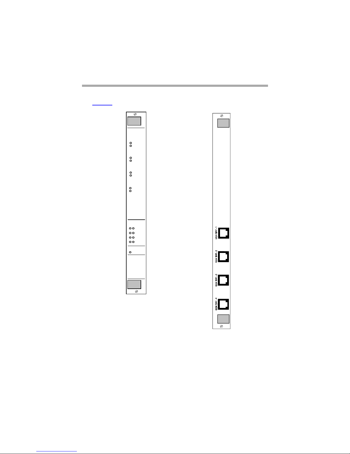
The front and rear panel layouts for the CBUQBR are shown below in
Figure 1.
Ch. in Use
CBU
Alert
B1
B2
BRI 2
B1
B2
BRI 3
B1
B2
BRI 1
B1
B2
BRI 4
ISDN
L1 L2
BRI 1
BRI 2
BRI 3
BRI 4
QBR
Figure 1 - CBUQBR Front and rear panels
Page 7

The Quad Basic Rate Module
80-14004000-01 1–3
The CBUQBR provides up to 8 x 64kbit/ s ‘B ’ channels, eac h channel c an
be switched to any ti me-slot on any of t he four 2.048 Mbit/s back plane
buses.
The CBUQBR will provide on demand indiv idual 64 kbit/s channels for
use by other application cards in the shelf . The other appl ication cards
are completely responsible for the provision of telephone numbers,
CLIDs, dial commands, timers, and call retry attempts.
Software download to the module is supported via the CBUGSM.
1.3 Shelf Power Loading
The CBUQBR requires the following current on the power rails:
+5V +12V -12V
300mA 5mA 5mA
When i nstalling cards int o either type of shelf , the instal lation engineer
must ensure that the shelf power supplies’ combined output can meet
both the overall power requirements and the individual rail current
requirem ents of all t he cards in the shelf. (Please refer to the relev ant
manuals for thi s inform ati on on the cards). This is tr ue whether allowing
for redundancy or not.
Warning:
The Shelf should be professionally installed by a competent
engineer. There are no operator serviceable parts inside the
unit and it should only be opened by a qualified service
engineer. The mains supply should be disconnected before
accessing the interior.
Gefäh! Bereich. Nur für fachpersonal. Nicht öffnen
berührungsgefahr!
Zone dangereuse! reservée au personnel autorisé. Ne pas
ouvrir. Tensions dangereuses.
Page 8

CBUQBR
User Manual
80-14004000-011–4
1.4 Switches and Jumpers
All switches and jumpers must only be changed by a competent
engineer.
1.4.1 8 Way DIL Switch S2 - poles 1-4
Pole 1
OFF (F) Reserved
Pole 2
OFF (F) ‘S’ bus power detection enabled
ON ‘S’ bus power detection disabled
Pole 3
OFF (F) Normal Operation
ON Factory Default.
(It must subsequently be turned OFF
again after powering up to perform a
factory default, to return the CBUQBR
back to normal operation)
Pole 4
OFF System Slave Function
ON (F) System Master Function.
This enables the call control and routing
functions, resident on the CBUQBR.
Poles 5-8
Variant selection, see section 1.4.2.
Page 9

The Quad Basic Rate Module
80-14004000-01 1–5
1.4.2 Product Variant - S2 Poles 5-8
Different operati onal m odes or produc t “vari ants” can be selec ted via t he
8 way DIL switch on the pcb, allowing several different countries and
variants to use the same software.
DIL switch S1 poles 5, 6, 7 and 8 define the variant in binary notation.
Pole 5 = L.S.B., pole 8 = M.S.B., (L.S.B.=Least Significant Bit,
M.S.B.=Most Significant Bit).
Variant Country DIL Switch Settings
Variant 0(F) Euro ISDN. UK and most
European countries:
poles 5,6,7,8 all
OFF.
Variant 2 Euro ISDN*. France and
Sweden:
pole 6 ON,
poles 5,7,8 OFF.
Variant 3 USA AT&T: poles 5,6 ON,
poles 7,8 OFF.
‘F’ is the f act ory sett ing, and m ust not be c hanged ot herwise m al f unct i on
may occur. All poles are ‘read’ by the software on power up.
*NOTE: Variant 2 does not have single octet information elements
present in the call setup message.
Most other countries with Euro-ISDN are likely to require Variant 0.
Please contact your Technical Support for further information.
NOTE: Variants 1-14 must not be set in the UK, otherwise the
Approval of this product will be invalidated. Access to the
interior to change these settings must only be made by a
competent engineer.
1.4.3 4 Way DIL Switch S3
Poles 1-4
ON (F) Not used
Page 10

CBUQBR
User Manual
80-14004000-011–6
1.4.4 Jumpers and Links
Front card:
These are all factory set and must not be changed.
Jumper Description
(F=Factory Set)
JP1-3 - Not used
JP4 - Clock post
JP5 OUT (F) Watchdog timer enabled
JP6 OUT (F) Rear card absence enables re-boot
JP7-11 MASTER (F) System Bus Master operation
SLAVE System Bus Slave operation
Rear card:
Jumper Description
(F=Factory Set)
JP1 OUT (F) Tx ISDN line 1 termination disabled
JP2 OUT (F) Rx ISDN line 1 termination disabled
JP3 OUT (F) Tx ISDN line 2 termination disabled
JP4 OUT (F) Rx ISDN line 2 termination disabled
JP5 OUT (F) Tx ISDN line 3 termination disabled
JP6 OUT (F) Rx ISDN line 3 termination disabled
JP7 OUT (F) Tx ISDN line 4 termination disabled
JP8 OUT (F) Rx ISDN line 4 termination disabled
Page 11

The Quad Basic Rate Module
80-14004000-01 1–7
Should problem s be found with long l engths of ISDN c able, the j umpers
can be put IN to enable the 120R termination resistors for each port
individually.
1.5 CBUQBR Status LEDs
The status LED’s are illuminated under the following conditions:
LED Colour Conditions
Channel in
Use
(B1/B2)
Green When a call is active,
i.e.
the relevant ‘B’
channel is in use (including in use for a
Talkwire call)
L 1 Green When ISDN Layer 1 (physical activation) is
active
L 2 Green When ISDN Layer 2 (LAPD) is active
ALERT Red When an ALERT is being sent to the CBUGSM
1.6 Management and Control
The CBUQBR operat es in conjunct ion with a CB UGSM f or c onfi gurati on
purposes so there is no directl y c onnec ted comm and port. Under normal
conditions the majority of commands are initiated by other application
cards so only a limited set of commands are available directly to the
user.
Please see the manual on the Shelf System s for details of how to use
the CBUGSM.
Page 12

Operation
80-14004000-01 2–1
2 Operation
2.1 Introduction
Each Basic Rate Interface on the CBUQBR operates as a TE. This
provi des 64kbit/s ‘B’ channels for t he consumpti on of other user cards in
the Shelf System . The CBUQBR operates as the sole prov ider of ‘B’channels within the Shelf.
The other appli cation car ds are completel y responsible f or the prov ision
of telephone numbers, CLID’s, dial commands, timers, call retry etc. the CBUQBR has no facility for storing these facilities.
2.2 ISDN Interfaces
Four Basic Rate ISDN ‘S’ interfaces are provided conforming to the I.420
standard.
Line termi nation resistors can be selected ( in or out) by jum pers on the
rear interf ace card. Somet imes terminat ion is required with long cable
lengths to the ISDN termination point.
2.3 Clocking
The clock for the system is derived from the network. One interf ac e acts
as a clock master and generates cloc k and frame sync f or the system.
The remainder the CBUQBR prov ides elastic buffering to remove any
clock phase jitter.
Page 13

CBUQBR
User Manual
80-14004000-012–2
The first interface (in the order 1, 2, 3, 4) that synchronises with the
network supplies clock to the system - if this clock source f ails the nex t
interf ace wit h a synchroni sed clock is used. If interface 4 is prov iding
clock and synchroni sation and it is lost, t hen interface 1 is tried. If no
clocks are in sync then a free running clock is supplied to the system.
2.4 Real Time Clock
A Real time clock functi on is provided by the operat ing system on the
CBUQBR. This software based real time clock facility calculates only
hours minutes and seconds. The time and date used is set and
maintained by CBUGSM automatically for all cards in the shelf.
2.5 ALERTS
There are three ALERTs specifi call y generated by t he CBUQBR. These
are output by the CBUQHSM on the Command and Alarms ports,
depending on the settings in the CBUGSM menus.
ALERT LAPD Activity
Sends an ALERT indicating the state of LAPD.
The ALERT message is:
ALERT LAPD Active
or
ALERT LAPD Inactive
as appropriate.
Page 14

Operation
80-14004000-01 2–3
ALERT System Clock
Sends an ALERT indicating the state of the
System Clock. There are three possible
messages associated with this ALERT :-
ALERT System clock free running
(When No BRI is in Sync or when the BRI that
was supplying system clock loses sync)
or
ALERT System clock gained from
BRI-n
(When a BRI acquires sync and provides
system clock)
or
ALERT System clock lost from BRI-n
(When a BRI loses sync and the next source
is hunted as appropriate)
Where n is the port number, 1 to 4
These ALERTs are only generated when the
CBUQBR is in Clock Master mode.
ALERT B-Channel
usage
Sends an ALERT indicating how many ‘B’
channels are in use. The ALERT message is:
ALERT B-Channel usage x,y
Where x and y are in the range 0 - 8 and :x is the number of channels in use
and y is the number of channels remaining
available
x + y = 8
These ALERTs can all be individually enabled or disabl ed. The Default is
Enabled.
Page 15

Command Menu
80-14004000-01 3–1
3 Command Menu
3.1 Introduction
The maj ority of CBUQ BR acti ons are init iated by other appli cati on car ds
via the CBUGSM so that only a small set of configurati on commands are
available to the user for this module.
3.2 Configuration
Owing to the nature of the CBUQBR hav ing 4 network port s, setting up
requires care and understanding to ensure that all the ports are
confi gured correctl y. Malf unction can easi ly be caused t hrough a f aulty
configuration. Time that is spent carefully on this is time well spent.
3.2.1 Configuration Principles
A few simple princi ples need to be foll owed for confi guration; these are
as follows:-
• Each port that is connected to the network must have its Line
Configuration (under Confi guration top menu) correctly specif ied for
both ‘B’ channels on each l ine. This i s i r r espect ive of whether the line
is a dual numbered l ine (a discrete num ber for each ‘B’ channel ), or
an MSN line, or single numbered sub-address conf igured line. The
Line Confi gurati on contai ns up to 7 digit s - which are the l ast 7 digi ts
of the line num ber. The l east num ber t hat m ust be ent ered i s the l ast
discrete ‘B’ channel digits, i. e. for num bers 123459 and 123460, the
Line Confi gurat i on m ust contai n at least t he num ber 59 f or B1 and 60
Page 16

CBUQBR
User Manual
80-14004000-013–2
for B2. The best practice is fill in the last complete num ber block, for
exampl e i n the UK the l ast 6 di git s (or 7 di git s f or ci ty num ber s). T he
number entered i s also used for dialli ng additional aggregati on calls
when using the CBUQHS.
• If any port is not connect ed to the network then it m ust have i ts line
configuration deleted for both ‘B’ channels. Any ports can be
disconnected, providing the Line Configuration menu reflects this.
• The Routing menu (under Configuration top menu) must be
confi gured to assign user port cards, e. g. CBUQHS or CBUQLS, and
their respecti v e ports. I f t he line i s an M SN ty pe or single numbered
sub-address type, the desired MSN or sub-address numbers must be
entered in the Set MSN and Set Subaddress sub-menus. (The
‘Record’ number is simply a numbered list and its number has no
relation to port numbering, card slot numbering or ‘B’ channel
numbering).
• When using with the CBUQHS one ex tra ‘B’ channel is requi red for
synchronisation purposes in addition to the number of ‘B’ channels
required for user port speed aggregation. For exam ple f or a 448kbit/s
call, seven ‘B’ channels are required for data plus one for
synchronisation, thus requiring 8 ‘B’ channels - all four BRI lines
which is the maximum. 512k aggregation is not possible with a
CBUQBR.
3.2.2 Suggested Configuration Method
The fol lowing i s a tried and prov en m ethod of conf iguri ng t he CBUQB R,
in the following order:-
1. Plug in the BRI lines int o the CBUQBR, m aking a note of all t he line
numbers versus CBUQBR ports.
2. Go to the Line configuration menu and enter each line number
against the Pri mary and Secondary entr ies, f or all ports connec ted t o
lines. The ‘P rimary ’ entry is the B1 num ber and ‘Secondary’ entr y is
the B2 number. For an MSN li ne, enter the desired MSN number,
e.g. Pri mary 123451, Secondar y 123452 ( assuming a base number of
123450, with a possible number range of 123450-123459). For a
single numbered line, enter the same number f or both Primary and
Secondary entries.
Page 17

Command Menu
80-14004000-01 3–3
3. Go to the Routi ng menu and select Set S lot/Port . S elect an unused
record number and f ill in the correct slot and port numbers for user
port cards. Repeat this using a dif fer ent record num ber f or each port
on all cards.
4. If using MSN lines, select Set MSN and enter the desired MSN
against each record for each user card slot and port.
5. If using sub-addressed lines, select Set Subaddress and enter the
desired sub-address against each record for each user card slot and
port.
6. Set any other parameters as required, e.g. ALERTs menu.
7. Your CBUQBR should now be set up correctly. It may be helpf ul to
test that the l ines are operat ional on eac h port. This can be done by
using an analogue t elephone dialling one number on each port and
checking that the L1 and L2 (ISDN Layer 1 and 2) LEDs alight for
each port on the front panel. The ‘B’ Channel in Use LED will
moment arily fl ash during the incoming cal l. If any port LEDs do not
light then either the line is disconnected or not operational on that
particul ar port. This m ust be corrected f irst bef ore attem pting to use
the system.
8. When dialli ng check that the correct L1 and L2 BRI LEDs correspond
to the number s di alled. If incorr ec t ports respond, check that the l ines
are plugged into the correct ports against the line configuration menu.
9. Hav ing got all lines operati onal, try maki ng and receivi ng calls from
the user port card. I f the system does not operat e successfully, try
the following:-
• Check the Line Configuration and Routing menus.
• Check that the ISDN lines used do support sub-addressing and
whether sub-addressing is presented from the call er (if set up on
the CBUQBR).
• Check that the I SDN li nes used do support MSN (if set up on the
CBUQBR).
The network provider will be able to provide information on the last two
points.
Page 18

CBUQBR
User Manual
80-14004000-013–4
3.3 Command and Parameter Structure
The CBUQBR uses a hierarchical command menu structure similar to
other Fivemere-Cabletron products. Some menu options are marked
with an asterisk (*) to indicate that they are unavailable - this is to
maintain the overall menu structure across the product range. The
following sub-sections describe the menus.
The foll owing comm ands have a special m eaning and are ex ecuted wit h
single keystrokes:-
S
Displays the status information for all channels of the module.
T
Returns to the top level menu.
X
Goes back (up) one level in the menu system.
3.4 Top level Menu
*) OPERATION
No operation menu is available.
B) CONFIGURATION
See section 3.5 below.
C) LOGOUT
Logs the user out of password
entry.
Page 19

Command Menu
80-14004000-01 3–5
3.5 Configuration menu
The first three menus are unav ailable - they are included to maintain the
menu structure across the product range. Refer to the Shelf Systems
manual for details of how to set these menus on the CBUGSM.
The (F) where shown is the factory default setting.
*) SYSTEM
*) COMMAND PORT
*) ALARM PORT
D) ALARMS
See Section 3.5.1
E) ROUTING
See Section 3.5.2
F) LINE CONFIGURATION
See Section 3.5.3
G) ISDN
See Section 3.5.4
H) CLOCK MODE
See Section 3.5.5
3.5.1 Alarms menu
A) ALERT LAPD ACTIVITY
A) ENABLED (F)
Sends an ALERT indicating whether
ISDN LAPD (Link layer) is active or
inactive. It must be active for the
PRIM to be able to make or receive
calls. The ALERT message is:
ALERT LAPD active
or
ALERT LAPD inactive
B) DISABLED
This ALERT is disabled.
Page 20

CBUQBR
User Manual
80-14004000-013–6
B) ALERT SYSTEM CLOCK
A) ENABLED (F)
Sends an ALERT indicating the state
of the System Clock. There are three
possible messages associated with
this ALERT :-
ALERT System clock free
running
(When No BRI is in Sync or when the
BRI that was supplying system clock
loses sync)
or
ALERT System clock gained
from BRI-n
(When a BRI acquires sync and
provides system clock)
or
ALERT System clock lost from
BRI-n
(When a BRI loses sync and the next
source is hunted as appropriate)
Where n is the port number, 1 to 4.
These ALERTs are only generated
when the CBUQBR is in Clock Master
mode.
B) DISABLED
This ALERT is disabled.
Page 21

Command Menu
80-14004000-01 3–7
C) ALERT B-CHANNEL USAGE
A) ENABLED (F)
Sends an ALERT indicating how
many ‘B’ channels are in use. The
ALERT message is:
ALERT B-Channel usage x,y
Where x and y are numerals in the
range 0 - 8 and :-
x is the number of channels in use
and y is the number of channels
remaining available.
x + y = 8.
B) DISABLED
This ALERT is disabled.
3.5.2 Routing menu
It is essential for the operation of the CBUQBR that Routing is
correctly set for every operational port of the application cards.
This menu bel ow defines how incomi ng calls are ‘m apped’ to user ports
by defining the MSN and/or sub-addresses for the record entries. To
each record number is assi gned an application card and its associat ed
port, also an MSN or sub-address.
In the case of absence of a sub-address or MSN from an incom ing call ,
the CBUQBR will attempt to match the ‘B’ channel to the recor d num ber.
You are advised however to ensure that both the network and your
CBUQBR are conf igured correctl y for eit her sub-address or MSN. This
is due to the likelihood of the incorrect destination being chosen
otherwise.
Note that parameter A) SET SLOT/PORT must be set for a particular
record before setting parameters B, C and D, otherwise the record
cannot be displayed and is not fully configured.
Page 22

CBUQBR
User Manual
80-14004000-013–8
A) SET SLOT/ PORT
ENTER
RECORD
(1-48):
The record number to be assigned
to an application card port. The
entry requires a [CR].
ENTER SLOT
REFERENCE:
This is the slot number that the
application card occupies starting
from 1. The entry requires a [CR].
ENTER PORT
REFERENCE:
The is the physical port number
(
e.g.
1-4 for CBUQLS) of the
application card. The entry
requires a [CR].
B) SET MSN
ENTER
RECORD
(1-48):
The record number to be assigned
with an MSN. The entry requires
a [CR].
ENTER MSN:
The MSN number of up to 20
digits for the port (for destination
of calls) must be entered here.
The entry requires a [CR].
The MSN number can be removed
by entering a [CR] on a blank line.
C) SET SUB ADDRESS
ENTER
RECORD
(1-48):
The record number to be assigned
with a sub-address. The slot/port
setting above will define which
card and port is assigned. The
entry requires a [CR].
ENTER
SUBADDRESS
The sub-address of up to 20 digits
for call destination must be
entered here. (This sub-address is
that used when matching incoming
calls, not the sub-address that is
sent with outgoing calls).
The sub-address can be removed
by entering a [CR] on a blank line.
Page 23

Command Menu
80-14004000-01 3–9
*) DEST PORT TYPE
Menu not available.
E) CLEAR RECORD
ENTER
RECORD:
The port number to be cleared
must be entered here. The entry
requires a [CR].
F) LIST RECORD
ENTER
RECORD:
The record number to be listed
must be entered here. The slot
and port routing for this port is
then displayed. The entry requires
a [CR].
G) LIST RECORDS 1-16
Slot and port routing for records
1-16 is displayed.
H) LIST RECORDS 17-32
Slot and port routing for records
17-32 is displayed.
I) LIST RECORDS 33-48
Slot and port routing for records
33-48 is displayed.
3.5.3 Line Configuration menu
For each selection, the following response is provided:
ENTER LINE NUMBER:
The Line Configurati on c ontains up to 7 digi ts - which are the last 7 digits
of the l ine number. The l east number that must be enter ed is the last
discrete ‘B’ channel di git s, i .e. f or num bers 123459 and 123460, t he Li ne
Configur ation m ust contai n at least t he number 59 f or B1 and 60 f or B2.
The best practice is fill in the last complete number block, for example in
the UK the last 6 digits (or 7 digits for city numbers). The number
entered is also used for diall ing additional aggregation call s when usi ng
the CBUQHS.
‘Primary’ refers to the B1 channel, Secondary the B2 channel.
Each entry requires a [CR].
Page 24

CBUQBR
User Manual
80-14004000-013–10
A) LINE 1 PRIMARY
B) LINE 1 SECONDARY
C) LINE 2 PRIMARY
D) LINE 2 SECONDARY
E) LINE 3 PRIMARY
F) LINE 3 SECONDARY
G) LINE 4 PRIMARY
H) LINE 4 SECONDARY
3.5.4 ISDN Menu
A) DISPLAY A) ENABLED
Displays information
messages from the ISDN
network.
B) DISABLED
(F)
Inhibits this display.
B) MULTIDROP A) ENABLED
Additional TE equipment can
be plugged into the BRI lines
in parallel with the CBUQBR.
B) DISABLED
(F)
Multidrop operation is
disabled.
3.5.5 Clock Mode
A) CLOCK MODE A) MASTER
The QBRM sources the clock
for the shelf from the network.
*) SLAVE
Menu is not available.
Page 25

European Approvals Information
80-14004000-01 4–1
4 European Approvals Information
The B.A.B.T. Pan European Approval number is as follows:
AA606781
The CBUQBR i s approved f or connection t o ISDN serv ices prov ided by
British Telecom PLC, or any similar telecommunications operator.
Page 26

Glossary of Terms
80-14004000-01 5–1
5 Glossary of Terms
Here are some of the most used abbrev iations in thi s manual with thei r
descriptions:-
BRI Basic Rate Interface
CBUGSM Cyber Backup Generic Shelf Manager Card
CBUPRI Cyber Backup Primary Rate Interface Module
CBUQBR Cyber Backup Quad Basic Rate Module
CBUQHS Cyber Backup Quad High Speed Module
CBUQLS Cyber Backup Quad Low Speed Module
CLID Calling Line Identity (the number of the caller
which is presented to the called party)
MSN Multiple Subscriber Number (an ISDN address
method of defining a specific user port for a call
destination)
NT Network Termination
TE Terminal Equipment
 Loading...