

Page 1

SmartSwitch 9000
9C214-3 AC Power Supply
Installation Guide
9032529-01
Page 2

Page 3

Notice
Notice
Cabletron Systems reserves the right to make changes in specifications and other information
contained in this document without prior notice. The reader should in all cases consult Cabletron
Systems to determine whether any such changes have been made.
The hardware, firmware, or software described in this manual is subject to change without notice.
IN NO EVENT SHALL CABLETRON SYSTEMS BE LIABLE FOR ANY INCIDENTAL, INDIRECT,
SPECIAL, OR CONSEQUENTIAL DAMAGES WHATSOEVER (INCLUDING BUT NOT LIMITED
TO LOST PROFITS) ARISING OUT OF OR RELATED TO THIS MANUAL OR THE INFORMATION
CONTAINED IN IT, EVEN IF CABLETRON SYSTEMS HAS BEEN ADVISED OF, KNOWN, OR
SHOULD HAVE KNOWN, THE POSSIBILITY OF SUCH DAMAGES.
© Copyright November 1998 by:
Cabletron Systems, Inc.
35 Industrial Way
Rochester, NH 03867-5005
All Rights Reserved
Printed in the United States of America
Order Number: 9032529-01
Cabletron Systems
Cabletron Systems, Inc.
CompuServe
i960 microprocessor
Ethernet
is a trademark of Xerox Corporation.
and
LANVIEW
is a registered trademark of CompuServe, Inc.
is a registered trademark of Intel Corp.
are registered trademarks, and
SmartSwitch
is a trademark of
i
Page 4

Notice
FCC Notice
This device complies with Part 15 of the FCC rules. Operation is subject to the following two
conditions: (1) this device may not cause harmful interference, and (2) this device must accept any
interference received, including interference that may cause undesired operation.
NOTE:
device, pursuant to Part 15 of the FCC rules. These limits are designed to provide reasonable
protection against harmful interference when the equipment is operated in a commercial envir onment.
This equipment uses, generates, and can radiate radio frequency energy and if not installed in
accordance with the operator’s manual, may cause harmful interference to radio communications.
Operation of this equipment in a residential area is likely to cause interference in which case the user
will be required to correct the interference at his own expense.
WARNING:
party responsible for compliance could void the user’s authority to operate the equipment.
This equipment has been tested and found to comply with the limits for a Class A digital
Changes or modifications made to this device which are not expressly approved by the
VCCI Notice
This is a Class A product based on the standard of the Voluntary Control Council for Interference by
Information Technology Equipment (VCCI). If this equipment is used in a domestic environment,
radio disturbance may arise. When such trouble occurs, the user may be required to take corrective
actions.
DOC Notice
This digital apparatus does not exceed the Class A limits for radio noise emissions from digital
apparatus set out in the Radio Interference Regulations of the Canadian Department of
Communications.
Le présent appareil numérique n’émet pas de bruits radioélectriques dépassant les limites applicables
aux appareils numériques de la class A prescrites dans le Règlement sur le brouillage radioélectrique
édicté par le ministère des Communications du Canada.
ii
Page 5

Notice
DECLARATION OF CONFORMITY
ADDENDUM
Application of Council Directive(s): 89/336/EEC
73/23/EEC
Manufacturer’s Name: Cabletron Systems, Inc.
Manufacturer’ s Address: 35 Industrial Way
PO Box 5005
Rochester, NH 03867
European Representative Name: Mr. J. Solari
European Representative Address: Cabletron Systems Limited
Nexus House, Newbury Business Park
London Road, Newbury
Berkshire RG13 2PZ, England
Conformance to Directive(s)/Product Standards:
EC Directive 89/336/EEC
EC Directive 73/23/EEC
EN 55022
EN 50082-1
EN 60950
Equipment Type/Environment:
Networking Equipment, for use in a
Commercial or Light
Industrial Environment.
We the undersigned, hereby declare, under our sole responsibility, that the equipment packaged with
this notice conforms to the above directives.
Manufacturer Legal Representative in Europe
Mr. Ronald Fotino Mr. J. Solari
____________________________________________________ ______________________________________________________
Full Name Full Name
Principal Compliance Engineer Managing Director - E.M.E.A.
____________________________________________________ ______________________________________________________
Title Title
Rochester, NH, USA Newbury, Berkshire, England
____________________________________________________ ______________________________________________________
Location Location
iii
Page 6

Notice
iv
Page 7

Contents
Chapter 1 Introduction
Using This Manual........................................................................................................ 1-1
The 9C214-3 Power Supply..........................................................................................1-1
Features ...................................................................................................................1-3
Power Distribution System.......................................................................................... 1-4
Related Manuals............................................................................................................ 1-4
Getting Help .................................................................................................................. 1-5
Chapter 2 Installing the 9C214-3 Power Supply
Unpacking the 9C214-3 Power Supply......................................................................2-1
Installing to the SmartSwitch 9000 Chassis...............................................................2-1
Powering Up the 9C214-3 Power Supply..................................................................2-3
Chapter 3 9C214-3 Power Supply Operation
Operating Functions..................................................................................................... 3-1
System Diagnostic Controller ..............................................................................3-2
Internal Temperature Sensor................................................................................3-2
Power Supply Cooling.......................................................................................... 3-2
LANVIEW LEDs.................................................................................................... 3-2
PWR Status LED.............................................................................................3-3
SMB Status LED..............................................................................................3-3
Power Supply Level Indicator LED............................................................. 3-4
Chapter 4 Specifications
Safety............................................................................................................................... 4-1
Service.............................................................................................................................4-1
Physical........................................................................................................................... 4-2
Environmental...............................................................................................................4-2
Universal AC Input.......................................................................................................4-2
Input Voltage .................................................................................................................4-2
Fusing ............................................................................................................................ 4-2
AC Input Connection ................................................................................................... 4-2
Output Voltage .............................................................................................................. 4-3
v
Page 8

Contents
vi
Page 9

Introduction
Using This Manual
Chapter 1
Read through this manual to become familiar with its contents and to gain an
understanding of the features and capabilities of the 9C214-3 power supply prior
to installing and operating it.
Chapter 1,
supply and its features. This chapter also includes a list of related manuals and
information on getting help.
Chapter 2,
unpacking, installing, and powering up the 9C214-3 power supply.
Chapter 3,
regarding the power supply operation.
Chapter 4,
supply.
Introduction , provides a brief description of the 9C214-3 power
Installing the 9C214-3 Power Supply , contains detailed steps for
9C214-3 Power Supply Operation , contains detailed information
Specifications , provides detailed specifications of the 9C214-3 power
The 9C214-3 Power Supply
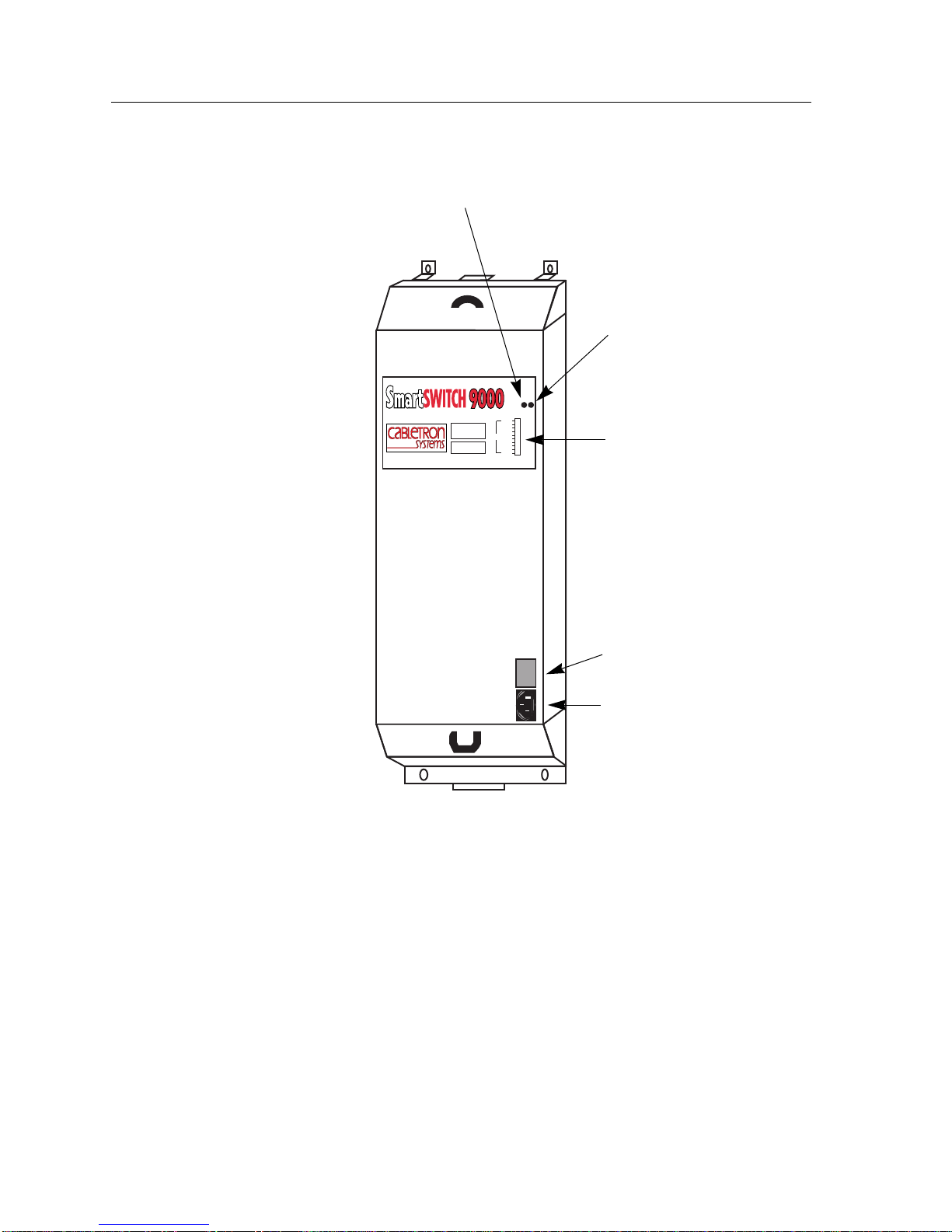
The 9C214-3 power supply, shown in Figure 1-1, is a 2000 watt, triple output
supply that provides power to the SmartSwitch 9000 chassis. At least one power
supply must be installed; however, additional power supplies can be installed to
achieve redundancy. When two or more power supplies are installed, the system
uses a current sharing scheme where, under all load conditions, each supply
provides power equally.
1-1
Page 10
Introduction
Power Supply
Status LED
SMB
Status
LED
P
S
W
N
R
B
POWER SUPPLY MODULE
9C214-3
Load
STATUS
100%
50%
0%
Power
Supply
Level
Indicator
LED
207-264v-12A
50-60 Hz
Figure 1-1. The 9C214-3 Power Supply
Power
Switch
AC
Power
Socket
1-2
Page 11

Features
Diagnostic Controller for Management
Introduction
Each 9C214-3 power supply has a diagnostic controller which includes a
microprocessor that monitors the numerous power supply functions available to
the Network Manager via LCD, as well as local and remote management.
Internal Temperature Sensor
Each 9C214-3 power supply has its own built-in temperature sensor for
monitoring and reporting its own internal temperature to the Network Manager
via LCD, as well as local and remote management.
Cooling Fan
The diagnostic controller increases or decreases the fan speed based on the
temperature of the power supply. In the event of microprocessor failure, fan
speed defaults to 100% to ensure protection of the power supply.
Thermal Overload Protection
A thermal shutdown circuit is included within each 9C214-3 power supply. This
circuit protects the power supply from overheating if a thermal overload occurs.
Automatic recovery takes place after the thermal overload condition is corrected.
Load Sharing
Each 9C214-3 power supply uses a current sharing scheme whereby if two power
supplies are used, under all load conditions, each supply provides 50% (± 5%) of
the required load on each output. This feature incr eases the life of a power supply.
Universal AC Input
The 9C214-3 power supply accepts AC input voltage ranging from 207–264 volts
at 50/60Hz.
Hot Swapping
9C214-3 power supplies can be installed or removed from the back of the chassis
while another power supply is operating without affecting network operation.
LANVIEW
®
LEDs
Each 9C214-3 power supply has three LANVIEW LEDS: the PWR Status LED
indicates the status of the 9C214-3 power output, the SMB Status LED indicates
the status of the diagnostic controller, and the Power Supply Level Indicator LED
indicates the percentage of the power supply load being used.
1-3
Page 12
Introduction
Power Distribution System
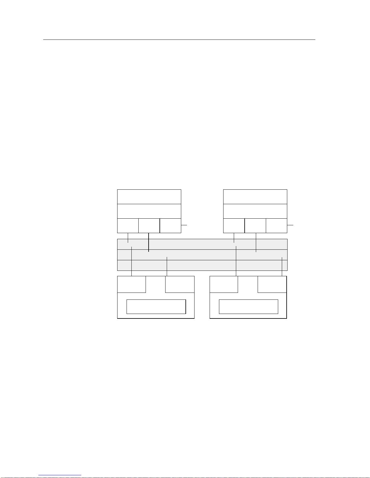
The SmartSwitch 9000 uses a distributed DC power distribution system
(Figure 1-2) similar to those used in super computers. Three separate power buses
are used to distribute DC power. The 48-volt DC System Power Bus, located on
the backplane, powers all modules and the system cooling fans. The Diagnostic
Power Bus provides 5 volts DC to all of the system’s diagnostic controllers and
the Environmental Module. The INB Termination Power Bus provides 3.3 volts
DC to the SmartSwitch 9000 INB termination modules (ITM).
To offer the greatest variety of power options, the 48-volt DC System Power Bus
and all components that use this bus are capable of operating using voltage
ranging from 40–60 volts DC. This capability allows the SmartSwitch 9000 to
operate from typical AC power and to char ge batteries in a battery backup unit or
operate on DC power , such as found in a central of fice or a battery backup system.
56 volts 5 volts 3.3 volts
DC/DC
Convertor
Related Manuals
The manuals listed below should be used to supplement the procedures and
technical data contained in this manual.
207 - 264 volts
AC Power Supply
Communications
Systems Components
INB
48 Volt System Power Bus
5 Volt Diagnostic Power Bus
3.3 Volt INB Termination Power Bus
Diagnostic
Controller
DC/DC
Convertor
207 - 264 volts
AC Power Supply
56 volts 5 volts 3.3 volts
Diagnostic
Controller
Communications
Systems Components
Figure 1-2. Distributed DC Power Distribution System
INB
SmartSwitch 9000 Installation Guide
SmartSwitch 9000 9C300-1 Environmental Module User’s Guide
In addition, each Interface Module has a user’s guide.
1-4
Page 13

Getting Help
For additional support related to this device or document, contact Cabletron
Systems using one of the following methods:
World Wide Web http://www.cab letron.com/
Phone (603) 332-9400
Internet mail [email protected]
FTP ftp://ftp.cabletron.com/
Login
Password
To send comments or suggestions concerning this document, contact the
Cabletron Systems Technical Writing Department via the following
email address: [email protected]
Make sure to include the document Part Number in the email message.
anonymous
your email address
Introduction
Before calling Cabletron Systems, have the following information ready:
• Your Cabletron Systems service contract number
• A description of the failure
• A description of any action(s) already taken to resolve the problem (e.g.,
changing mode switches, rebooting the unit, etc.)
• The serial and revision numbers of all involved Cabletron Systems products in
the network
• A description of your network environment (layout, cable type, etc.)
• Network load and frame size at the time of trouble (if known)
• The device history (i.e., have you returned the device before, is this a recurring
problem, etc.)
1-5
Page 14

Introduction
1-6
Page 15

Chapter 2
Installing the 9C214-3 Power Supply
At least one power supply must be installed on the rear of the SmartSwitch 9000
chassis. Additional power supplies can be added to achieve redundancy.
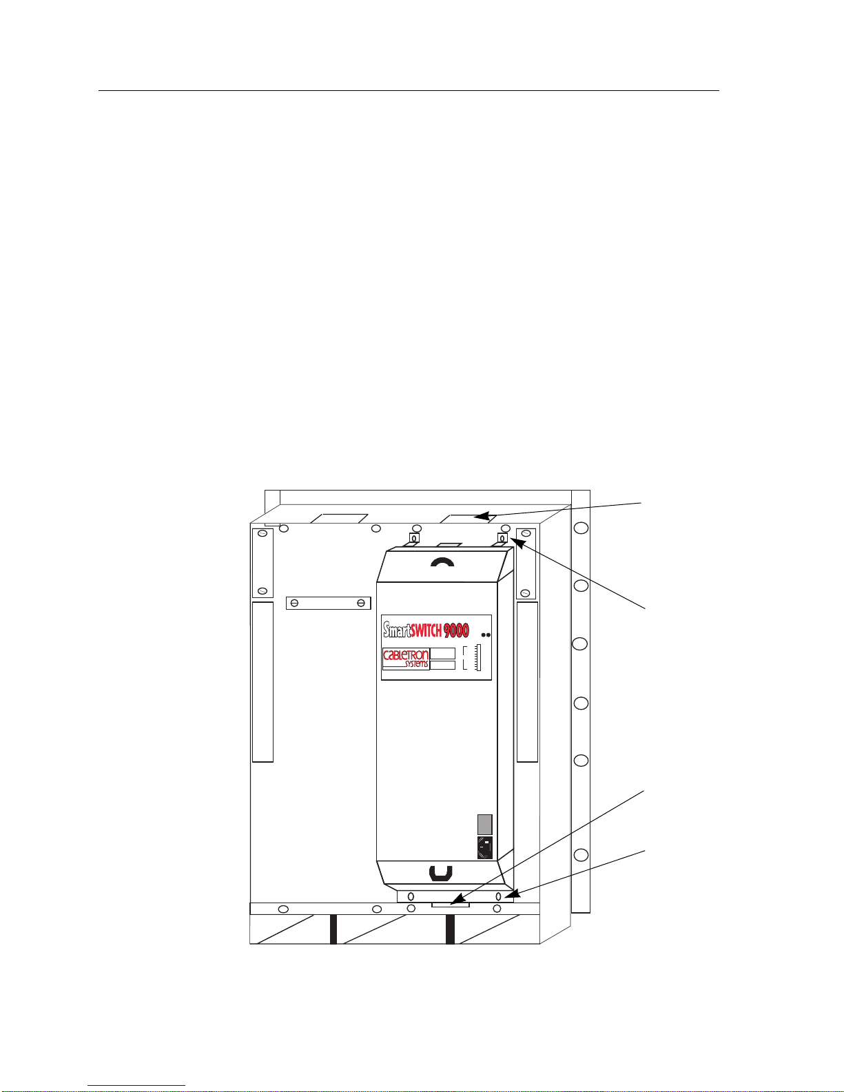
A power supply is installed by plugging it into either the left or right power
supply connector on the SmartSwitch 9000 chassis, as shown in Figure 2-1.
Unpacking the 9C214-3 Power Supply
1. Unpack the power supply by removing it from the shipping box and sliding
the two foam end caps off the unit. (Save the shipping box and packing
materials in the event the power supply must be reshipped.)
2. Remove the power supply from the protective plastic bag. (Save the bag in the
event the power supply must be reshipped.)
3. Examine the power supply carefully, checking for damage. If any damage
exists, DO NOT install the power supply. Immediately contact the Cabletron
Systems Global Technical Assistance Center.
Installing to the SmartSwitch 9000 Chassis
1. Loosen and remove the two screws from one of the power supply connector
covers on the rear of the SmartSwitch 9000 chassis.
2. Remove the cover . (Keep the cover in the event you need to r emove the power
supply. The cover must be replaced to protect the connector.)
2-1
Page 16
Installing the 9C214-3 Power Supply
3. Hold the power supply by the handles on the top and bottom of the unit and
do the following:
a. Align the power supply so that the lip on the bottom and the hook on the
top are slightly above the corresponding slots on the chassis.
b. Ease the power supply down until the hook catches the slot on the top and
the tab is inserted in the slot on the bottom.
c. Plug the power supply in the connector on the back of the chassis by
pushing the power supply in until its frame touches the surface of the
SmartSwitch 9000 chassis. Do not force the power supply in place. If
significant resistance is encountered before the frame is flush with the
chassis, remove the power supply, realign it, and push it in again.
d. Secure the power supply to the chassis by tightening the two screws on
the top and two screws on the bottom of the power supply. For proper
chassis grounding, the four screws must be properly tightened.
21
Slot on
Chassis
.
.
.
.
.
POWER SUPPLY MODULE
9C214-3
P
W
R
STATUS
100%
50%
Load
0%
.
.
.
.
.
.
.
S
N
.
B
.
.
.
.
.
.
.
.
.
Securing
Screws
Tab
207-264v-12A
50-60 Hz
Securing
Screws
Figure 2-1. Installing the 9C214-3 Power Supply
2-2
Page 17

Installing the 9C214-3 Power Supply
Powering Up the 9C214-3 Power Supply
Before you turn the power switch on, make sure that the Environmental Module and all
NOTE
Interface Modules have been properly installed.
The 9C214-3 Power Supply is powered up by following the steps below:
1. Plug one end of the power cord (supplied with the power supply) into the AC
power socket on the lower right front corner of the power supply.
2. Plug the other end of the power cord into an AC r eceptacle. Turn on the power
supply using the switch located near the power socket.
3. The power supply uses a soft start feature and does a pre-power diagnostic
check. Outputs become enabled within 5 seconds of turning the power on.
4. Check to make sure that
a. The PWR Status LED is green.
b. The SMB Status LED is green.
If the LEDs are any color other than green, refer to
LANVIEW LEDs in Chapter 3.
2-3
Page 18

Installing the 9C214-3 Power Supply
2-4
Page 19

Chapter 3
9C214-3 Power Supply Operation
The 9C214-3 power supply can operate with input voltages ranging from
207–264 VAC at 50/60 Hz. Each 9C214-3 provides a maximum of 2000 watts of
power to the SmartSwitch 9000.
When two power supplies are installed, the system uses a current sharing scheme
where, under all load conditions, each supply provides 50% (± 5%) of the requir ed
load.
Each 9C214-3 power supply converts the 207–264 VAC to three different DC
outputs for internal use by the system. Each of these outputs is described below.
• 56 volts supplied to the 48-volt DC System Power Bus for use throughout the
chassis for each installed module and the Environmental Module system fans.
• 5 volts supplied to the Diagnostic Power Bus used by the diagnostic controllers
and the Environmental Module.
• 3.3 volts supplied to the INB Termination Power Bus.
Operating Functions
The 9C214-3 power supply includes the following functions:
• System Diagnostic Controller
• Internal Temperature Sensor
• Power Supply Cooling
3-1
Page 20
9C214-3 Power Supply Operation
System Diagnostic Controller
The System Diagnostic Controller is composed of a Z-80 microprocessor and its
supporting logic. The System Diagnostic Controller monitors the power supply’s
input and output power parameters as well as the temperature and fan status. In
addition, the System Diagnostic Controller adjusts fan speed and controls the
LANVIEW diagnostic LEDs. The information gathered by the System Diagnostic
Controller is available to the network manager via the LCD, as well as via local
and remote management. If the System Diagnostic Controller fails, the 9C214-3
power supply has been designed to continue to function and supply power to the
system.
Internal T emperature Sensor
Each 9C214-3 power supply has a built-in temperature sensor for monitoring its
own internal temperature. The results of the monitoring are available to the
network manager via LCD, as well as local and remote management.
Power Supply Cooling
Each 9C214-3 power supply includes an internal cooling fan. The System
Diagnostic Controller monitors the internal temperature of the power supply and
increases or decreases the fan speed based on that temperature. If the System
Diagnostic Controller fails, fan speed defaults to 100% to ensure protection of the
power supply.
LANVIEW LEDs
The LANVIEW LEDs on the back of the 9C214-3 power supply may be used as an
aid for troubleshooting.
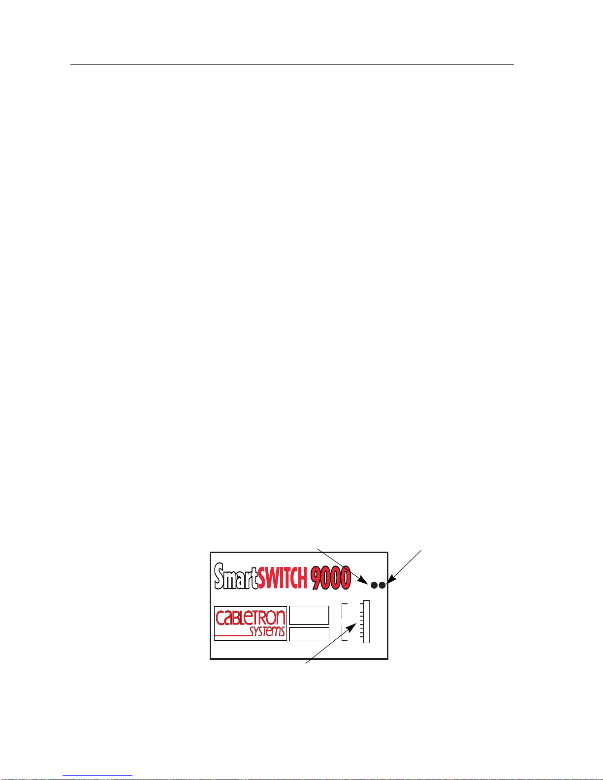
There are three LANVIEW LEDs visible to the user (Figure 3-1): the PWR Status
LED, the SMB Status LED, and the Power Supply Level Indicator LED.
PWR STATUS LED SMB STATUS LED
P
S
W
N
R
B
STATUS
Figure 3-1. 9C214-3 Power Supply LANVIEW LEDs
3-2
POWER SUPPLY MODULE
Power Supply Level Indicator LED
9C214-3
Load
100%
50%
0%
Page 21

PWR Status LED
The PWR Status LED indicates the status of a power supply’s input and output.
The possible states and descriptions of the PWR Status LED are listed in Table 3-1.
9C214-3 Power Supply Operation
Table 3-1. PWR Status LED
LED Color State Description
Green Functional The 56-volt, 5-volt, and 3.3-volt outputs
are within established tolerances.
Yellow Crippled Not fully operational (56-volt output is
not within established tolerances due to
lack of AC input).
SMB Status LED
The SMB Status LED indicates the status of the diagnostic controller. The possible
states and descriptions of the SMB Status LED are listed in Table 3-2.
Red Fault One of the system power supply outputs
is out of regulation.
Off Power off Module powered off.
Table 3-2. SMB Status LED
LED Color State Description
Green Functional Fully operational.
Yellow/Green Booting Flashes yellow and green while booting.
Yellow Testing Power up testing being performed.
Yellow (Flashing) Crippled Limited functionality of the diagnostic
controller or fan failure.
Red Reset Normal power-up reset.
Red (Flashing) Failed Fatal error has occurred.
Off Power off Module powered off.
3-3
Page 22

9C214-3 Power Supply Operation
Power Supply Level Indicator LED
The Power Supply Level Indicator LED indicates the percentage of the power
supply load. The possible states and descriptions of the Power Supply Level
Indicator LED are listed in Table 3-3.
Table 3-3. Power Supply Level Indicator LED
Segment
Number(s)
1–5 Green 10–50% of power load
6–9 Green 60–90% of power load
6–9 Yellow 60–90% of power load
10 Yellow Greater than 90% of
11 Red Overload condition
LED Color State Description
being used.
being used. No parallel
power supply
operational.
being used. Parallel
supply(ies) installed;
however , redundancy not
available.
power supply being
used.
exists.
No action
necessary.
No action
necessary.
Add an
additional power
supply if
redundancy is
desired.
Add an
additional power
supply for
redundancy.
Add an
additional power
supply or reduce
number of
modules in the
chassis.
3-4
Page 23

Specifications
Safety
Chapter 4
CAUTION
The 9C214-3 power supply, when properly installed on the SmartSwitch 9000
chassis, complies with the following safety specifications and standards:
• UL 1950
• CSA C22.2 No. 950
• EN 60950
• IEC 950
• EMI Requirements of FCC Part 15 Class A
• EN 55022 Class A
• VCCI Class I
• EMC requirements of
Service
It is the responsibility of the person who sells the system to which the modules
!
will be a part to ensure that the total system meets allowed limits of conducted
and radiated emissions.
EN 50082-1
IEC 801-2 ESD
IEC 801-3 Radiated susceptibility
IEC 801-4 EFT
The 9C214-3 power supply is designed with the following service capability:
MTBF (MIL-STD-217): >200,000 hours projected
MTTR: <.50 hour
4-1
Page 24

Specifications
Physical
Dimensions
60.96 H x 19.05 W x 13.97 D centimeters
(24 H x 7.5 W x 5.5 D inches)
Weight
Unit: 8.6 kilograms (19 lbs.)
Shipping: 9.9 kilograms (22 lbs.)
Environmental
Operating Temperature: 5–40° C, 51–104° F
Operating Humidity: 5% to 95%
Cooling: 2.15 cubic meters (76 cubic feet) of air per minute drawn
Universal AC Input
Each 9C214-3 power supply accepts input voltage ranging from 207–264 volts at
50–60 Hz.
Input V oltage
Each 9C214-3 power supply will draw the following current at maximum load:
11.2A @207 volts
8.7A @264 volts
Fusing
The AC input to the 9C214-3 power supply has a non-user serviceable 250 volt
15-amp fuse.
through the chassis
AC Input Connection
The AC input connector is an IEC type entry requiring the use of the Cabletronapproved power cord provided with the 9C214-3 power supply.
4-2
Page 25

Output V oltage
Each 9C214-3 power supply is capable of generating the following output
voltages:
56.0 volts @35A
3.3 volts @17A
5.1 volts @18A
Specifications
4-3
Page 26

Specifications
4-4
 Loading...