

Cabletron Systems SmartSwitch 6000, SmartSwitch 6H202-24, SmartSwitch 6H252-17, 6E233-49, 6H253-13 Installation & User Manual
...Page 1
6H202-24, 6H252-17, and 6H262-18
SmartSwitch 6000 Interface Modules
Installation User’s Guide
FAST ENET
6H202-24
CPU
DPX
SPD
FAST ENET
6H252-17
RESET
COM
12
2X
34
4X
56
6X
78
8X
910
10X
11 12
12X
13
14
14X
15 16
16X
17 18
18X
19 20
20X
21 22
22X
23 24
24X
RX
LED
MODE
TX
RESET
COM
DPX
RX
CPU
SPD
TX
12
2X
34
4X
56
6X
78
8X
910
10X
11 12
12X
13
14
14X
15 16
16X
FAST ENET
6H262-18
CPU
DPX
SPD
RESET
COM
12
2X
34
4X
56
6X
78
8X
910
10X
11 12
12X
13
14
14X
15 16
16X
RX
LED
MODE
TX
9033378
G
P
I
M
1
G
P
I
M
2
Page 2

Page 3

Only qualified personnel should perform installation procedures.
NOTICE
Cabletron Systems reserves the right to make changes in specifications and other information contained in this document
without prior notice. The reader should in all cases consult Cabletron Systems to determine whether any such changes
have been made.
The hardware, firmware, or software described in this manual is subject to change without notice.
IN NO EVENT SHALL CABLETRON SYSTEMS BE LIABLE FOR ANY INCIDENTAL, INDIRECT, SPECIAL, OR
CONSEQUENTIAL DAMAGE S WHATSOEVER (INCLUDING BUT NOT LIMITED TO LOST PROFITS) ARISING OUT OF OR
RELATED TO THIS MANUAL OR THE INFORMATION CONTAIN ED IN IT, EVEN IF CABLETRON SYSTEMS HAS BEEN
ADVISED OF, KNOWN, OR SHOULD HAVE KNOWN, THE POSSIBILITY OF SUCH DAMAGES.
Cabletron Systems, Inc.
35 Industrial W a y
Rochester, NH 03866-5005
2000 by Cabletron Systems, Inc.
All Rights Reserved
Printed in the Unite d States of America
Order Number: 9033378 January 2000
Cabletron Systems, QuickSET, SecureFast, and LANVIEW are registered trademarks and SmartSwitch is a
trademark of Cabletron Systems, Inc.
All other product names mentioned in this manual may be trademarks or registered trademarks of their respective
companies.
i
Page 4

FCC NOTICE
This device complie s with P a rt 15 of th e FCC rul es. Ope rat ion is sub ject to th e fo llowing two conditions: (1) this device
may not cause harmful interference, and (2) this device must accept any interference received, including interference that
may cause un desired operation.
NOTE: This equipment has been tested and found to comply with the limits for a Class A digital device, pursuant to
Part 15 of the FCC rules. These limits are designed to provide reasonable protection against harmful in t erference when
the equipment is operated in a commercial environment. This equipment uses, generates, and can radiate radio frequency
energy and if not installed in accordance with the operat or’s manual, may cause harmful interference to r a dio
communications. Operation of this equipment in a residential area is likely to cause interference in which case the user
will be required to correct the interference at his own expense.
WARNING: Changes or modific ations ma de to th is de vice which ar e not e xpre ssly ap pro ved by the p arty r espons ible f or
compliance could void the user’s authority to operate the equipment.
INDUSTRY CANADA NOTICE
This digital apparatus does not exceed the Class A limits for radio noise emissions from digital apparatus set out in the
Radio Interference Regulations of the Canadian Department of Communications.
Le présent appareil numérique n’émet pas de bruits radioélectriques dépassant les limites applicables aux appareils
numériques de la class A prescrites dans le Règlement sur le brouillage radioélectrique édicté par le ministère des
Communications d u C anada.
VCCI NOTICE
This is a Class A product based on the standard of the Voluntary Control Council for Interference by Information
T echnolog y Equipment (VCCI). If this equipment is used in a domestic en vironment, radio disturbance may arise. When
such trouble occurs, the user may be required to take corrective actions.
ii
Page 5

CABLETRON SYSTEMS, INC.
PROGRAM LICENSE AGREEMENT
IMPORTANT:THIS LICENSE APPLIES FOR USE OF PRODUCT IN THE FOLLOWING
GEOGRAPHICAL REGIONS:
CANADA
MEXICO
CENTRAL AMERICA
SOUTH AMERICA
BEFORE OPENING OR UTILIZING THE ENCLOSED PRODUCT, CAREFULLY READ
THIS LICENSE AGREEMENT.
This document is an agreement (“Agreement”) between You, the end user, and Cabletron Systems, Inc. (“Cabletron”)
that sets forth your rights and obligations with respect to the Cabletron software program (“Program”) in the package.
The Program may be contained in firmware, chips or other media. UTILIZING THE ENCLOSED PRODUCT, YOU
ARE AGREEING TO BECOME BOUND BY THE TERMS OF THIS AGREEMENT, WHICH INCLUDES THE
LICENSE AND THE LIMITATION OF WARRANTY AND DISCLAIMER OF LIABILITY. IF YOU DO NOT
AGREE TO THE TERMS OF THIS AGREEMENT, RETURN THE UNOPENED PRODUCT TO CABLETRON OR
YOUR DEALER, IF ANY, WITHIN TEN (10) DAYS FOLLOWING THE DATE OF RECEIPT FOR A FULL
REFUND.
IF YOU HAVE ANY QUESTIONS ABOUT THIS AGREEMENT, CONTACT CABLETRON SYSTEMS
+1- 603-332-9400. Attn: Legal Department.
1. LICENSE. You have the right to use only th e o ne ( 1) c op y of th e Pr og ram pr o v ide d in this pa c k ag e su bje ct to th e
terms and conditions of this License Agreement.
You may not copy, reproduce or transmit any part of the Program except as permitted by the Copyright Act of the
United States or as authorized in wri ting by Cabletron.
2. OTHER RESTRICTIONS. You may not reverse engineer, decompile, or disassemble the Pro gr am.
3. APPLICABLE LAW. This License Agreement shall be interpreted and governed under the laws and in the state
and federal courts of New Hampshire. You accept the personal jurisdiction and venue of the New Hampshire courts.
4. EXPORT REQUIREMENTS. You understand that Cabletron and its Affiliates are subject to regulation by
agencies of the U. S. Government, in cluding the U.S. De partment of Commerce, which prohibit export or divers ion of
certain technical products to certain co untries, unless a license to e xport the product is obtained from the U.S . Government
or an exception from obtaining such license may be relied upon by the exporting party.
If the Program is exported from the United States pursuant to the License Exception CIV under the U.S. Export
Administration Regulations, You agree that You are a civil end user of the Program and agree that You will use the
Program for civil en d uses only and not for mi litary pu rpo s es.
iii
Page 6

If the Program is exported from the United States pursuant to the License Exception TSR under the U.S. Export
Administration Regulations, in addition to the restriction on transfer set forth in Sections 1 or 2 of th is Agreement, You
agree not to (i) reexport or release the Program, the source code for the Program or technology to a national of a country
in Country Groups D:1 or E:2 (Albania, Armenia, Azerbaijan, Belarus, Bulgaria, Cambodia, Cuba, Estonia, Georgia,
Iraq, Kazakhstan, Kyrgyzstan, Laos, Latvia, Libya, Lithuania, Moldova, North Korea, the People’s Republic of China,
Romania, Russia, Rwanda, Tajikistan, Turkmenistan, Ukraine, Uzbekistan, Vietnam, or such other countries as may be
designated by the United States Government), (ii) export to Country Groups D:1 or E:2 (as de fine d herein) the direct
product of the Pro gram or t he tec hn olog y, if such foreign produ ce d direc t p rod uc t is su bj ec t to national security controls
as identified on the U.S. Commerce Control List, or (iii) if the direct product of the technology is a com pl ete plant o r
any major component of a plant, export to Country Groups D:1 or E:2 the direct product of the plant or a major
component thereof, if such foreign produced direct product is subject to national security controls as identified on the
U.S. Commerce Control List or is subject to State Department controls under the U.S. Munitions List.
5. UNITED STATES GOVERNMENT RESTRICTED RIGHTS. The enclosed Prod uc t (i ) was d eve lop e d so lely
at private expense; (ii) conta ins “restricted computer software ” submitted with restricted rights in accordance with section
52.227-19 (a) through (d) of the Commercial Computer Software-Restricted Rights Clause and its successors, and (iii) in
all respects is proprietary data belonging to Cabletron and/or its suppliers. For Department of Defense units, the Product
is considered commercial computer software in accordance with DFARS section 227.7202-3 and its successors, and use,
duplication, or disclosure by the Government is subject to restrictions set forth herein.
6. EXCLUSION OF WARRANTY. Except as may be specifically provided by Cabletron in writing, Cabletr on
makes no warranty , expressed or impl ied, concerning t he Program (inclu ding its documentation and media).
CABLETRON DISCLAIMS ALL WARRANTIES, OTHER THAN THOSE SUPPLIED TO YOU BY
CABLETRON IN WRITING, EITHER EXPRESS OR IMPLIED, INCLUDING BUT NO T LIMITED TO IMPLIED
WARRANTIES OF MERCHANTABILITY AND FITNESS FOR A PARTICULAR PURPOSE, WITH RESPECT TO
THE PROGRAM, THE ACCOMPANYING WRITTEN MATERIALS, AND ANY ACCOMPANYING HARDWARE.
7. NO LIABILITY FOR CONSEQUENTIAL DAMAGES. IN NO EVENT SHALL CABLETRON OR ITS
SUPPLIERS BE LIABLE FOR ANY DAMAGES WHATSOEVER (INCLUDING, WITHOUT LIMITATION,
DAMAGES FOR LOSS OF BUSINESS, PROFITS, BUSINESS INTERRUPTION, LOSS OF BUSINESS
INFORMATION, SPECIAL, INCIDENTAL, CONSEQUENTIAL, OR RELIANCE DAMAGES, OR OTHER LOSS)
ARISING OUT OF THE USE OR INABILITY TO USE THIS CABLETRON PRODUCT, EVEN IF CABLETRON
HAS BEEN ADVISED OF THE POSSIBILITY OF SUCH DAMAGES. BECAUSE SOME STATES DO NOT
ALLOW THE EXCLUSION OR LIMITATION OF LIABILITY FOR CONS EQUENTIAL OR INCIDENTAL
DAMAGES, OR IN THE DURATION OR LIMITATION OF IMPLIED W ARRANTIES IN SOME INSTANCES, THE
ABOVE LIMITATION AND EXCLUSIONS MAY NOT APPLY TO YOU.
iv
Page 7

CABLETRON SYSTEMS SALES AND SERVICE, INC.
PROGRAM LICENSE AGREEMENT
IMPORTANT : THIS LICENSE APPLIES FOR USE OF PRODUCT IN THE UNITED S TATES OF AMERICA
AND BY UNITED STATES OF AMERICA GOVERNMENT END USERS.
BEFORE OPENING OR UTILIZING THE ENCLOSED PRODUCT, CAREFULLY READ
THIS LICENSE AGREEMENT.
This document is an agreement (“Agreement”) between Y ou, the end user, and Cabletron Systems Sales and Service, Inc.
(“Cabletron”) that sets forth your rights and obligations with respect to the Cabletron software program (“Program”) in
the package. The Program may be contained in firmware, chips or other media. UTILIZING THE ENCLOSE D
PRODUCT, YOU ARE AGREEING TO BECOME BOUND BY THE TERMS OF THIS AGREEMENT, WHICH
INCLUDES THE LICENSE AND THE LIMITATION OF WARRANTY AND DISCLAIMER OF LIABILITY. IF
YOU DO NOT AGREE TO THE TERMS OF THIS AGREEMENT, RETURN THE UNOPENED PRODUCT TO
CABLETRON OR YOUR DEALER, IF ANY, WITHIN TEN (10) DAYS FOLLOWING THE DATE OF RECEIPT
FOR A FULL REFUND.
IF YOU HAVE ANY QUESTIONS ABOUT THIS AGREEMENT, CONTACT CABLETRON SYSTEMS
+1-603-332-9400. Attn: Legal Department.
1. LICENSE. You have the right to use only the one (1) copy of the Program provided in this package subject to the
terms and conditions of this License Agreement.
You may not copy, reproduce or transmit any part of the Program except as permitted by the Copyright Act of the
United States or as authorized in wri ting by Cabletron.
2. OTHER RESTRICTIONS. You may not reverse engineer, decompile, or disassemble the Program.
3. APPLICABLE LAW. This License Agreement shall be interpreted and governed under the laws and in the state
and federal courts of New Hampshire. You accept the personal jurisdiction and venue of the New Hampshire courts.
4. EXPORT REQUIREMENTS. You understand that Cabletron and its Affiliates are subject to regulation by
agencies of the U. S. Government, in cluding the U.S. De partment of Commerce, which prohibit export or divers ion of
certain technical products to certain co untries, unless a license to e xport the product is obtained from the U.S . Government
or an exception from obtaining such license may be relied upon by the exporting party.
If the Program is exported from the United States pursuant to the License Exception CIV under the U.S. Export
Administration Regulations, You agree that You are a civil end user of the Program and agree that You will use the
Program for civil en d uses only and not for mi litary pu rpo s es.
If the Program is exported from the United States pursuant to the License Exception TSR under the U.S. Export
Administration Regulations, in addition to the restriction on transfer set forth in Sections 1 or 2 of this Agreement, You
agree not to (i) reexport or release the Program, the source code for the Program or technology to a national of a country
in Country Groups D:1 or E:2 (Albania, Armenia, Azerbaijan, Belarus, Bulgaria, Cambodia, Cuba, Estonia, Georgia,
Iraq, Kazakhstan, Kyrgyzstan, Laos, Latvia, Libya, Lithuania, Moldova, North Korea, the People’s Republic of Ch ina,
Romania, Russia, Rwanda, Tajikistan, Turkmenistan, Ukraine, Uzbekistan, Vietnam, or such other countri es as may be
designated by the Uni ted States Government), (ii) export to Countr y Groups D:1 or E:2 (as d efine d herein) the direct
product of the Pro gra m or th e te chn olo g y, if such foreign produc e d dire c t p rod uc t is su bjec t to na tio n al securi ty c o ntro ls
as identified on the U.S. Commerce Control List, or (iii) if th e direct product of the technology is a complete plant o r
any major component of a plant, export to Country Groups D:1 or E:2 the direct product of the plant or a major
component thereof , if such foreig n pro duc ed dire ct produc t is subje ct to natio n al security controls as identified on the
U.S. Commerce Control List or is subject to State Department controls under the U.S. Munitions List.
v
Page 8

5. UNITED STATES GOVERNMENT RESTRICTED RIGHTS. The enclosed Prod uc t (i ) was d eve lop e d so lely
at private expense; (ii) conta ins “restricted computer software ” submitted with restricted rights in accordance with section
52.227-19 (a) through (d) of the Commercial Computer Software-Restricted Rights Clause and its successors, and (iii) in
all respects is proprietary data belonging to Cabletron and/or its suppliers. For Department of Defense units, the Product
is considered commercial computer software in accordance with DFARS section 227.7202-3 and its successors, and use,
duplication, or disclosure by the Government is subject to restrictions set forth herein.
6. EXCLUSION OF WARRANTY. Except as may be specifically provided by Cabletron in writing, Cabletron
makes no warranty, expressed or implied, concernin g the Program (including its documentation and media).
CABLETRON DISCLAIMS ALL WARRANTIES, OTHER THAN THOSE SUPPLIED TO YOU BY
CABLETRON IN WRITING, EITHER EXPRESS OR IMPLIED, INCLUDING BUT NO T LIMITED TO IMPLIED
WARRANTIES OF MERCHANTABILITY AND FITNESS FOR A PARTICULAR PURPOSE, WITH RESPECT TO
THE PROGRAM, THE ACCOMPANYING WRITTEN MATERIALS, AND ANY ACCOMPANYING HARDWARE.
7. NO LIABILITY FOR CONSEQUENTIAL DAMAGES. IN NO EVENT SHALL CABLETRON OR ITS
SUPPLIERS BE LIABLE FOR ANY DAMAGES WHATSOEVER (INCLUDING, WITHOUT LIMITATION,
DAMAGES FOR LOSS OF BUSINESS, PROFITS, BUSINESS INTERRUPTION, LOSS OF BUSINESS
INFORMATION, SPECIAL, INCIDENTAL, CONSEQUENTIAL, OR RELIANCE DAMAGES, OR OTHER LOSS)
ARISING OUT OF THE USE OR INABILITY TO USE THIS CABLETRON PRODUCT, EVEN IF CABLETRON
HAS BEEN ADVISED OF THE POSSIBILITY OF SUCH DAMAGES. BECAUSE SOME STATES DO NOT
ALLOW THE EXCLUSION OR LIMITATION OF LIABILITY FOR CONS EQUENTIAL OR INCIDENTAL
DAMAGES, OR IN THE DURATION OR LIMITATION OF IMPLIED W ARRANTIES IN SOME INSTANCES, THE
ABOVE LIMITATION AND EXCLUSIONS MAY NOT APPLY TO YOU.
vi
Page 9

CABLETRON SYSTEMS LIMITED
PROGRAM LICENSE AGREEMENT
IMPORTANT: THIS LICENSE APPLIES FOR THE USE OF THE PRODUCT IN THE FOLLOWING
GEOGRAPHICAL REGIONS:
EUROPE
MIDDLE EAST
AFRICA
ASIA
AUSTRALIA
P ACIFIC RIM
BEFORE OPENING OR UTILIZING THE ENCLOSED PRODUCT, CAREFULLY READ
THIS LICENSE AGREEMENT.
This document is an agreement (“Agreement”) between Y ou, the end user, and Cabletron Systems Limited (“Cabletron”)
that sets forth your rights and obligations with respect to the Cabletron software program (“Program”) in the package.
The Program may be contained in firmware, chips or other media. UTILIZING THE ENCLOSED PRODUCT, YOU
ARE AGREEING TO BECOME BOUND BY THE TERMS OF THIS AGREEMENT, WHICH INCLUDES THE
LICENSE AND THE LIMITATION OF WARRANTY AND DISCLAIMER OF LIABILITY. IF YOU DO NOT
AGREE TO THE TERMS OF THIS AGREEMENT, RETURN THE UNOPENED PRODUCT TO CABLETRON OR
YOUR DEALER, IF ANY, WITHIN TEN (10) DAYS FOLLOWING THE DATE OF RECEIPT FOR A FULL
REFUND.
IF YOU HAVE ANY QUESTIONS ABOUT THIS AGREEMENT, CONTACT CABLETRON SYSTEMS
+1-603-332-9400. Attn: Legal Department.
1. LICENSE. You have the right to use only th e o ne ( 1) c op y of th e Pr og ram pr o v ide d in this pa c k ag e su bje ct to th e
terms and conditions of this License Agreement.
You may not copy, reproduce or transmit any part of the Program except as permitted by the Copyright Act of the
United States or as authorized in wri ting by Cabletron.
2. OTHER RESTRICTIONS. You may not reverse engineer, decompile, or disassemble the Pro gr am.
3. APPLICABLE LAW. This License Agreement shall be governed in accordance with English law. The English
courts shall have exclusive jurisdiction in the event of any disputes.
4. EXPORT REQUIREMENTS. You understand that Cabletron and its Affiliates are subject to regulation by
agencies of the U. S. Government, in cluding the U.S. De partment of Commerce, which prohibit export or divers ion of
certain technical products to certain co untries, unless a license to e xport the product is obtained from the U.S . Government
or an exception from obtaining such license may be relied upon by the exporting party.
If the Program is exported from the United States pursuant to the License Exception CIV under the U.S. Export
Administration Regulations, You agree that You are a civil end user of the Program and agree that You will use the
Program for civil en d uses only and not for mi litary pu rpo s es.
vii
Page 10

If the Program is exported from the United States pursuant t o the License Exception TSR under the U.S. Export
Administration Regulations, in addition to the restriction on transfer set forth in Sections 1 or 2 of this Agreement, You
agree not to (i) reexport or release the Program, the source code for the Program or technology to a national of a country
in Country Groups D:1 or E:2 (Albania, Armenia, Azerbaijan, Belarus, Bulgaria, Cambodia, Cuba, Estonia, Georgia,
Iraq, Kazakhstan, Kyrgyzstan, Laos, Latvia, Libya, Lithuania, Moldova, North Korea, the People’s Republic of China,
Romania, Russia, Rwanda, Tajikistan, Turkmenistan, Ukraine, Uzbekistan, Vietnam, or such other countries as may be
designated by the United States Government), (ii) export to Country Groups D:1 or E:2 (as de fine d herein) the direct
product of the Pro gram or t he tec hn olog y, if such foreign produ ce d direc t p rod uc t is su bj ec t to national security controls
as identified on the U.S. Commerce Control List, or (iii) if the direct product of the technology is a com pl ete plant o r
any major component of a plant, export to Country Groups D:1 or E:2 the direct product of the plant or a major
component thereof, if such foreign produced direct product is subject to national security controls as identified on the
U.S. Commerce Control List or is subject to State Department controls under the U.S. Munitions List.
5. UNITED STATES GOVERNMENT RESTRICTED RIGHTS. The enclosed Prod uc t (i ) was d eve lop e d so lely
at private expense; (ii) conta ins “restricted computer software ” submitted with restricted rights in accordance with section
52.227-19 (a) through (d) of the Commercial Computer Software-Restricted Rights Clause and its successors, and (iii) in
all respects is proprietary data belonging to Cabletron and/or its suppliers. For Department of Defense units, the Product
is considered commercial computer software in accordance with DFARS section 227.7202-3 and its successors, and use,
duplication, or disclosure by the Government is subject to restrictions set forth herein.
6. EXCLUSION OF WARRANTY. Except as may be specifically provided by Cabletron in writing, Cabletron
makes no warranty, expressed or implied, concernin g the Program (including its documentation and media).
CABLETRON DISCLAIMS ALL WARRANTIES, OTHER THAN THOSE SUPPLIED TO YOU BY
CABLETRON IN WRITING, EITHER EXPRESS OR IMPLIED, INCLUDING BUT NO T LIMITED TO IMPLIED
WARRANTIES OF MERCHANTABILITY AND FITNESS FOR A PARTICULAR PURPOSE, WITH RESPECT TO
THE PROGRAM, THE ACCOMPANYING WRITTEN MATERIALS, AND ANY ACCOMPANYING HARDWARE.
7. NO LIABILITY FOR CONSEQUENTIAL DAMAGES. IN NO EVENT SHALL CABLETRON OR ITS
SUPPLIERS BE LIABLE FOR ANY DAMAGES WHATSOEVER (INCLUDING, WITHOUT LIMITATION,
DAMAGES FOR LOSS OF BUSINESS, PROFITS, BUSINESS INTERRUPTION, LOSS OF BUSINESS
INFORMATION, SPECIAL, INCIDENTAL, CONSEQUENTIAL, OR RELIANCE DAMAGES, OR OTHER LOSS)
ARISING OUT OF THE USE OR INABILITY TO USE THIS CABLETRON PRODUCT, EVEN IF CABLETRON
HAS BEEN ADVISED OF THE POSSIBILITY OF SUCH DAMAGES. BECAUSE SOME STATES DO NOT
ALLOW THE EXCLUSION OR LIMITATION OF LIABILITY FOR CONS EQUENTIAL OR INCIDENTAL
DAMAGES, OR IN THE DURATION OR LIMITATION OF IMPLIED W ARRANTIES IN SOME INSTANCES, THE
ABOVE LIMITATION AND EXCLUSIONS MAY NOT APPLY TO YOU.
viii
Page 11

SAFETY INFORMATION
CLASS 1 LASER TRANSCEIVERS
THE GPIM-01 AND GPIM-09 GIGABIT ETHERNET MODULES
USE CLASS 1 LASER TRANSCEIVERS.
READ THE FOLLOWING SAFETY INFORMATION BEFORE INSTALLING OR OPERATING
THESE MODULES.
The Class 1 laser transceivers use an optical feedback loop to maintain Class 1 operation limits. This control loop
eliminates the need for maintenance checks or adjustments. The output is factory set, and does not allow any user
adjustment. Class 1 Laser transceivers comply with the following safety standards:
• 21 CFR 1040.10 and 104 0. 11 U. S. Department of Health and Hum a n S erv ic es (FDA).
• IEC Publication 825 (International Electrotechnical Commission).
• CENELEC EN 608 25 (E uropean Committe e fo r El ec tro technical Standardization).
When operating within their performance limitations, laser transceiver output meets the Class 1 accessible emission limit
of all three standards. Class 1 levels of laser radiat ion are not considered hazardous.
SAFETY INFORMATION
CLASS 1 LASER TRANSCEIVERS
LASER RADIATION AND CONNECTORS
When the connector is in place, all laser radiation remain s within the fiber. The maximum amount of radiant power
exiting the fiber (under normal conditions) is -12.6 dBm or 55 x 10
Removing the optical connector from the transceiver allows laser radiation to emit directly from the optical port. The
maximum radiance from the optical port (under worst case conditions) is
0.8 W cm
Do not use optical instruments to view the laser output. The use of optical instruments to view laser output
increases eye hazard. When viewing the output optical port, power must be removed from the network adapter.
-2
or 8 x 10³ W m2 sr-1.
-6
watts.
ix
Page 12

DECLARATION OF CONFORMITY
Application of Council Directive(s): 89/336/EEC
73/23/EEC
Manufacturer’s Name: Cabletron Systems, Inc.
Manufacturer’s Address: 35 Industrial Way
PO Box 5005
Rochester, NH 03867
European Represent ative Name: Mr. J. Solari
European Representative Address: Cabletron Systems Limited
Nexus House, Newbury Business Park
London Road, Newbury
Berkshire RG14 2PZ, England
Conformance to Directive(s)/Product Standards: EC Di re ctive 89/336/EEC
EC Directive 73/23/ EEC
EN 55022
EN 50082-1
EN 60950
Equipment Type/Environment: Networking Equipment, for use in a Commercial
or Light Industrial Environment.
We the undersigned, hereby declare, under our sole responsibility, that the equipment packaged with this
notice conforms to the above directives.
Manufacturer Legal Representative in Europe
Mr. Ronald Fotino Mr. J. Solari
___________________________________ ___________________________________
Full Name Full Name
Compliance Engineering Manager Managing Director - E.M.E.A.
___________________________________ ___________________________________
Title Title
Rochester, NH, USA Newbury, Berkshire, England
___________________________________ ___________________________________
Location Location
x
Page 13

Contents
Figures............................................................................................................................ xiv
Tables..............................................................................................................................xv
ABOUT THIS GUIDE
Using This Guide................ ....... ....................................... ...................................... ......xvii
Structure of This Guide ............................................................................................... xviii
Related Manuals ...........................................................................................................xix
Document Conventions..................................................................................................xx
1
INTRODUCTION
1.1 Overview.........................................................................................................1-1
1.1.1 Connectivity........................................................................................1-3
1.1.2 Auto-Negotiation ................................................................................1-3
1.1.3 Runtime IP Address Discovery ..........................................................1-3
1.1.4 Full Duplex Switched Ethernet...........................................................1-4
1.1.5 SmartTrunk.........................................................................................1-4
1.1.6 Remote Monitoring (RMON) .............................. ....... ...... ....... ...... ......1-4
1.1.7 Broadcast Suppression......................................................................1-5
1.1.8 Port/VLAN Redirect Functions ...........................................................1-5
1.1.9 Rate Limiting ......................................................................................1-5
1.1.10 GARP Switch Operation.....................................................................1-6
1.1.11 Flow Control.......................................................................................1-6
1.1.12 802.1 Port Priority ..............................................................................1-6
1.1.13 Management ......................................................................................1-7
1.1.14 Switching Options ..............................................................................1-7
1.1.15 Distributed Chassis Management ......................................................1-7
1.1.16 Optional HSIMs and VHSIMs.............................................................1-7
1.1.17 Optional GPIMs..................................................................................1-8
1.1.18 Standards Compatibilit y ......................... ...................................... ......1-8
1.1.19 LANVIEW Diagnostic LEDs ...............................................................1-9
1.1.20 Year 2000 Compliance.......................................................................1-9
1.2 Getting Help ....................................................................................................1-9
xi
Page 14

2
NETWORK REQUIREMENTS
2.1 SmartTrunk......................................................................................................2-1
2.2 10BASE-T Network.........................................................................................2-1
2.3 100BASE-TX Network.....................................................................................2-2
2.4 1000Base-SX and -LX Network......................................................................2-2
3
4
INSTALLATION
3.1 Unpacking the Module ....................................................................................3-2
3.2 Installing HSIM or VHSIM Options..................................................................3-2
3.3 Installing GPIM Options ..................................................................................3-2
3.4 Installing the Module into the 6C105 Chassis.................................................3-2
3.5 Connecting to the Network..............................................................................3-5
3.5.1 Connecting Twisted Pair Cables to Fixed Ports.................................3-5
3.6 Installing GPIMs..............................................................................................3-8
3.7 GPIM Network Connections..........................................................................3-10
3.7.1 GPIM-09 Connection Using Multim ode Cable ............................. ....3-11
3.7.2 Connecting the GPIM.......................................................................3-12
3.8 Completing the Installation............................................................................3-14
TROUBLESHOOTING
4.1 Using LANVIEW..............................................................................................4-1
4.1.1 The LED Mode Switch .......................................................................4-2
4.2 GPIM LED Descriptions for the 6H262-18 ......................................................4-6
4.3 Redundancy....................................................................................................4-7
4.4 Troubleshooting Checklist...............................................................................4-8
4.5 Using the RESET Button...............................................................................4-12
A
xii
SPECIFICATIONS
A.1 Module Specifications.....................................................................................A-1
A.2 Physical Properties .........................................................................................A-1
A.3 Environmental Requirements..........................................................................A-1
A.4 Input/Output Ports...........................................................................................A-2
A.5 COM Port Pinout Assignments .......................................................................A-3
A.6 Regulatory Compliance......................... ....... ...... ....... ...... ...... ..........................A -3
Page 15

B
GPIM SPECIFICATIONS
B.1 Gigabit Ethernet Specifications.......................................................................B-1
B.1.1 GPIM-01 Specifications (1000Base-SX)............................................B-1
B.1.2 GPIM-09 Specifications (1000Base-LX) ............................................B-2
B.2 Physical and Environmental Specifications.....................................................B-2
B.3 Regulatory Compliance...................................................................................B-3
C
INDEX
SWITCH SETTINGS, UPGRADES, AND INSTALLATIONS
C.1 Setting the Mode Switches............................................................................. C-1
C.2 SIMM Upgrade............................................................................................... C-3
C.2.1 Locating SIMMs ................................................................................ C-3
C.2.2 Installing the DRAM SIMM..................... ...... ...... ....... ...... ....... ...... ..... C-4
C.3 Installing Optional High Speed Interface Modules......................................... C-5
xiii
Page 16

Figures
Figure Page
1-1 T he 6 H20 2-24, 6H252- 17, and 6H26 2-18 Sma rtSwi tches..................... ...... ....... ...... ......1-2
3-1 Instal li ng an Interface Mod ule ................................ ...... ....... ...... ...... ....... ...... ....... ...... ......3-4
3-2 Connecting a Twisted Pair Segment to the SmartSwitch................................................3-6
3-3 Crossover Cable RJ45 Pinouts.......................................................................................3-7
3-4 Straight-Through Cable RJ45 Pinouts.............................................................................3-7
3-5 GPIM Connector..............................................................................................................3-8
3-6 Installing a GPIM into the 6H262-18 ...............................................................................3-9
3-7 Fiber Optic Port Designations .......................................................................................3-10
3-8 GPIM-09 Launch Mode Conditioning Cable Connection...............................................3-11
3-9 Fiber Optic GPIM Connections......................................................................................3-13
3-10 6H262-18 with Two Fiber Optic GPIM Ports .................................................................3-14
4-1 LANVIEW LEDs ..............................................................................................................4-3
4-2 LANVIEW LEDs for the GPIM.........................................................................................4-6
4-3 Reset Button..................................................................................................................4-12
C-1 Module Mode Switch Location/Component Layout........................................................ C-2
C-2 SIMM Slot Locations ...................................................................................................... C-3
C-3 Installing the DRAM......... ....................................... ...................................... ....... ........... C-4
C-4 HSIM and VHSIM Connector Locations......................................................................... C-5
xiv
Page 17

Tables
Table Page
1-1 GPIM Options . ....................................... ...... ....................................... .........................1- 8
3-1 Contents of Shipping Container...................................................................................3-2
4-1 LANVIEW LEDs for the Module...................................................................................4-4
4-2 Speed and Full Duplex LED Indications ......................................................................4-5
4-3 GPIM LED Functionality.................. ....... ...... ....... ...... ....... ...................................... ......4-7
4-4 Fault Identification........................................................................................................4-8
4-5 Power System Troubleshooting...................................................................................4-9
4-6 Firmware Troubleshooting .........................................................................................4-10
4-7 Management System Troubleshooting ......................................................................4-10
4-8 Device Setup Troubleshooting...................................................................................4-11
A-1 COM Port Pin Assignments......................................................................................... A-3
B-2 GPIM-01 Operating Range.......................................................................................... B-1
B-1 GPIM-01 Optical Specifications................................................................................... B-1
B-3 GPIM-09 Optical Specifications................................................................................... B-2
B-4 GPIM-09 Operating Range.......................................................................................... B-2
B-5 GPIM Physical Properties ........................................................................................... B-2
B-6 GPIM Environmental Requirements............................................................................ B-2
B-7 GPIM Safety and EMC Requirements......................................................................... B-3
xv
Page 18

xvi
Page 19

About This Guide
Welcome to th e Cabletron Systems 6H202-24, 6H252-17, and 6H262-18 SmartSwitch 6000
Interface Modules Installation User’s Guide. This guide describes the SmartSwitch Interface
Modules and provides information concerning network requirements, installation, and
troubleshooting . For information about how to use Local Management to co nfi gure and m anage
the SmartSwitch se r ies, refer to the SmartSwitch Series 6H202, 6H203, 6H252, 6H253, 6H258,
6H259, 6H262, 6E233, and 6E253 Local Management User’s Guide.
Important Notice
Depending on the firmware version used in the SmartSwitch, some features described in this
document may not be supported. Refer to the Release Notes shipped with the device to determine
which features are supported.
USING THIS GUIDE
Read through this guide completely to understand the SmartSwitch module features, capabilities,
and Local Management functions.
A general working knowledge of Fast Ethernet and IEEE 802.3 type data communications
networks and their physical layer components is helpful when using these devices.
NOTE
In this document, the SmartSwitch Interface Modules may also be referred to as
SmartSwitches or modules. When differences between the modules are described, the
modules will be referred to by name.
xvii
Page 20

Structure of This Guide
STRUCTURE OF THIS GUIDE
This guide is organized as follows:
This guide provides preliminary information that will aid in using this manual, lists te chnology
and user guides that may help the user set up and manage the SmartSwitches, and gives
instructions on how to get help from Cabletron Systems .
Chapter 1, Introduction, describes the features of the SmartSwitches.
Chapter 2, Network Requirements, outlines th e network requirements that must be met before
installing the SmartSwitches into the 6C105 SmartSwitch 6000 chassis.
Chapter 3, Installation, provides instruction s on how to ins tall a module in the chas sis and connect
segments.
Chapter 4, Troubleshooting, describes the SmartSwitch LANVIEW LEDs that enable quick
diagnosis of network/operational problems.
Appendix A, Specifications, contains information on functionality and operating specifications,
connector pinouts, environmental requirements, and physical properties.
Appendix B, GPIM Specificat i ons, contains the GPIM specifications for the optional GPIMs for
the 6H262-18.
Appendix C, Switch Settings, Upgrades, and Installations, describes how to set the Mode
Switches, and includes upgrade information on the SmartSwitches.
xviii
Page 21

Related Manuals
RELATED MANUALS
The following manuals may help the user to set up and manage the SmartSwitch modules:
• SmartSwitch Series 6H20 2, 6H203, 6H252, 6H2 53, 6H258, 6H259, 6 H262, 6E233, a nd 6E253
Local Management User’s Guide
• 6C105 SmartSwitch 6000 Overview and Setup Guide
• Ethernet Technology Guide
• Cabling Guide
• 802.1Q VLAN User’s Guide
• SmartTrunk User’s Guide
The following manuals, as applicable, may help the user to set up and manage the SmartSwitches:
• HSIM-A6DP User’s Guide
• HSIM-F6 User’s Guide
• HSIM-FE6 User’s Guide
• HSIM-W6 User’s Guide
• HSIM-W84 User’s Guide
• HSIM-W87 User’s Guide
• HSIM-G01/G09 User’s Guide
• VHSIM-G6 User’s Guide
• VHSIM-A6DP User’s Guide
• WAN Series Loca l Management User’s Guide
• VHSIM-A6DP User’s Guide
The HSIM-W6 Installation Guide, the HSIM-W84 Installation Guide, and the WAN Series Local
Management User’s Guide are included on the QuickSET CD-ROM and, along with the other
manuals referenced above, can be obtained on the World Wide Web in Adobe Acrobat Portable
Document Format (PDF) at the following site: http://www.cabletron.com/
NOTE
All documentation for Cabletron Systems SecureFast VLAN Manager software can be
found on the VLAN Manager CD-ROM.
xix
Page 22

Document Conventions
DOCUMENT CONVENTIONS
The following conventions are used throughout this document:
NOTE
TIP
CAUTION
Note symbol. Calls the reader’s attention to any item of information that may be of
special importance.
Tip symbol. Conveys helpful hints concerning procedures or actions.
Caution symbol. Contains information essential to avoid damage to the equipment.
!
Electrical Hazard Warning symbol. Warns against an action that could result in
personal injury or death due to an electrical hazard.
xx
Page 23

1
Introduction
This chapter introduces the 6H202-24, 6H252-17, and 6H262-18 SmartSwitch 6000 interface
modules and provides information about how to obtain additional support from Cabletron
Systems.
Important Notice
Depending on the firmware version used in the SmartSwitches, some features described in this
document may not be supported. Refer to the Release Notes shipped with the device to determine
which features are supported.
1.1 OVERVIEW
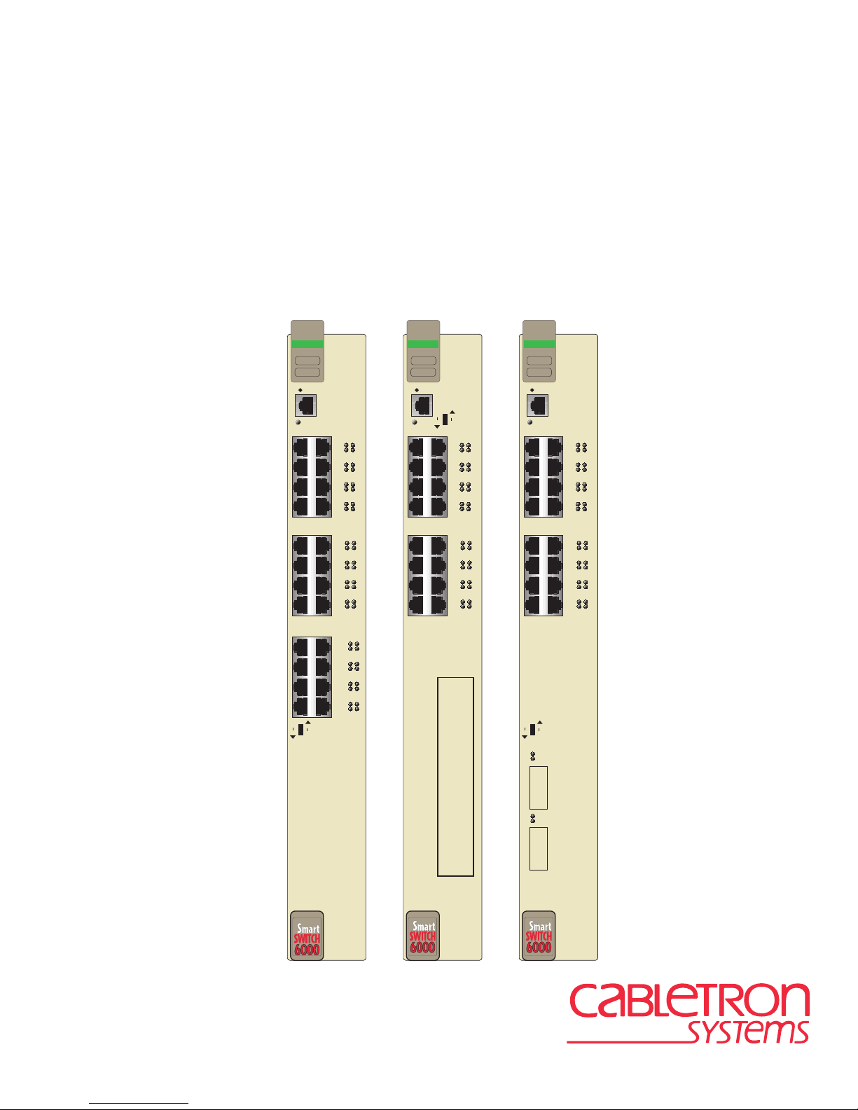
The SmartSwitches shown in Figure 1-1 are Ethernet/Fast Ethernet interface modules for
Cabletron Systems 6C105 chassis. The 6H202-24 has 24 RJ45 switched ports. The 6H252-17 has
16 RJ45 switched ports and 1 slot for an optional High Speed Interface Module (HSIM) or Very
High Speed Interf ace Modu le (VHSI M), an d the 6 H262- 18 has 1 6 RJ45 swi tched p orts and 2 sl ots
for Gigabit Port Interface Modules (GPIMs).
The SmartSwitches can be used to connect individual high-bandwidth user devices, such as
workstations, or to provide a central switching point for multiple 10/100 Mbps Fast Ethernet
segments. The optional HSIMs provide one or more high speed uplinks to networking
technologies such as Gigabit Ethernet, Fast Ethernet, Fiber Distributed Data Interface (FDDI),
Wide Area Network (WAN) and Asynchronous Transfer Mode (ATM). Some HSIMs can provide
additional Fast Ethernet ports in varying media types. The optional VHSIMs provide very high
speed uplinks t o netw or king t echnol ogies such as ATM and Gigabit Etherne t. The optio nal GPI Ms
provide connectivity to Gigabit Ethernet using fiber optic cable.
SmartSwitch ports can be configured to control frame traffic several ways, including prioritizing
traffic flow according to protocol type. SmartSwitches can also be configured to establish Virtual
Local Area Networks (VLANs) and control the flow of frames associated with each VLAN
according to priority and Ether type. Detailed information about VLANs is provided in the Local
Management User’s Guide.
Introduction 1-1
Page 24

Overview
Network
Ports 1-24
FAST ENET
6H202-24
RESET
CPU
LED
Mode
Switch
Port
LEDs
Ports
1-16
FAST ENET
6H262-18
RESET
CPU
COM
12
System
LED
2X
34
4X
56
Port
6X
Status
LEDs
78
8X
910
10X
11 12
12X
13
14
14X
15 16
16X
FAST ENET
6H252-17
COM Port
COM
10X
12X
14X
16X
System
LED
12
2X
34
4X
56
6X
78
8X
Network
Ports
1-16
910
11 12
Port
Status
13
14
LEDs
15 16
17 18
RESET
COM
DPX
CPU
SPD
COM Port
RX
TX
12
2X
34
4X
56
6X
8X
Status
78
Network
910
10X
11 12
12X
13
14
14X
15 16
16X
18X
19 20
20X
21 22
22X
23 24
24X
Figure 1-1 The 6H202-24, 6H252-17, and 6H262-18 SmartSwitches
1-2 Introduction
LED Mode
Switch
DPX
RX
LED
MODE
SPD
TX
LED Mode
VHSIM/
HSIM Slot
Switch
GPIM
Slot
DPX
RX
LED
MODE
SPD
TX
G
P
I
M
1
G
P
I
M
GPIM
Status
LEDs
2
Page 25

Overview
1.1.1 Connectivity
The SmartSwitch modules conn ect to Ethernet netwo rks or worksta tions t hrough t he RJ45 p orts on
the front panel. These ports are IEEE 802.3 10BASE-T and IEEE 802.3u 100BASE-TX
compliant. The ports support Category 5 Unshielded Twisted Pair cables with an impedance
between 85 and 111 ohms at lengths up to 100 meters for both 10 Mbps and 100 Mbps Ethernet
connections. They also support Category 3 for 10 Mbps, but not 100 Mbps Ethernet connections.
The 6H252-17 has a slot for an optional HSIM or VHSIM to provide additional connectivity to
various networking technologies.
The 6H262-18 has 2 GPIM slots for optional GPIMs that can provide additional connectivity to
Gigabit Ethernet, operating in full duplex mode. One of the ports is active and the other is
redundant. Redundancy is triggered based on link activity. GPIM 1 is the active port by default.
1.1.2 Auto-Negotiation
The twisted pair ports on the front panel of the SmartSwitch modules have the ability to
auto-negotiate the type of connection required to provide a link to another device. During
Auto-Negotiation, two devices automatically exchange information “telling” each other what their
operating capab ilit ies ar e. The Au to-Ne got iat ion fe ature tar get s th e maximu m capab ilit ies th at can
be reached betw een the t wo de vices . F or ex ample, the Smart Switches adjust to 100 Mbps when the
device on the other end of the connection can also adjust between 10 Mbps or 100 Mbps. If the
device on the other end of the connection can only operate at 10 Mbps, then the SmartSwitches
adjust to 10 Mbps operation.
When Auto-Negotiation is supported at both ends of a link, the two devices dynamically adjust to
full or half duplex operation based on the maximum capability that can be reached between the
two devices. If the device connected to the SmartSwitch cannot auto-negotiate, the module
interface operates according to the capability of the other device.
1.1.3 Runtime IP Address Discovery
This feature enable s the modul es to aut omatic ally ac cept an I P addres s from a Boot St rap Prot ocol
(BootP) server on the network into NVRAM without requiring a user to enter an IP address
through Local Management.
When the modules are connected to the network and powered up, Runtime IP Address Discovery
(RAD) checks the modu le s f or an IP address. If one has not yet been assigned (module and 6C105
chassis IP ad dre ss set to 0.0.0.0), RAD checks to see if an y o f t he modul e interfaces have a link. If
so, RAD sends out Reverse Address Resolution Protocol (RARP) and BootP requ est s to obtain an
IP address from a RARP or BootP server on the network.
Introduction 1-3
Page 26

Overview
The RAD requests start at an interval of one per second. The interval then doubles after every
transmission until an interval of 300 seconds is reached. At this point, the interval remains at 300
seconds. The RAD req uests conti nue unti l an IP addr ess is rece i v ed from a RARP o r BootP serv er,
or an IP address is entered using Local Management.
NOTE
The module will reboot after RAD is successful.
1.1.4 Full Duplex Switched Ethernet
Each switched Fast Ethernet port on the SmartSwitches supports 10/100 Mbps operation and can
be configured to operate in Full Duplex Switched Ethernet (FDSE) mode. FDSE allows each port
to provide up to 200 Mbps of bandwidth.
1.1.5 SmartTrunk
SmartTrunk, also referred to as SmartTrunking, is Cabletron Systems’ terminology for load
balancing or load sharing. SmartTrunk technology provides an easy-to-implement mechanism to
group, or aggregate, multiple links of any technology together to scale the backbone bandwidth
beyond the limitations of a si ngle link. All links are user-configurable so administrators can scale
the backbone bandwidth by adding SmartTrunk links. The benefits of SmartTrunking include the
following:
• All purchased bandwidth is used.
• Distributed, resilient links increase reliability and perf ormance.
• Multiple technologies are supported within a single trunk for maximum flexibility.
For more information on SmartTrunk configuration, refer to the Cabletron Systems SmartTrunk
User’s Guide.
1.1.6 Remote Monitoring (RMON)
The SmartSwitches support all nine Ethernet RMON groups. The Statistics, Alarms, Events and
History groups are enabled on all ports by default.
Cabletron Systems RMON Actions is a vendor-specific extension of RMON and provides the
ability to set an “Action” on any SNMP MIB variable. The Action can be triggered by setting an
RMON Event and/or Alarm. An example of an Action would be to turn off a MIB-2 interface if a
broadcast threshold is crossed.
1-4 Introduction
Page 27

Overview
1.1.7 Broadcast Suppression
Broadcast Suppres sion enabl es a user to se t a desi red limit of recei v e broadc ast frames per port/pe r
second to be forwa rded out the other port s on the mo dule up to the se t limit . An y broadc ast fr ames
above this specifie d limit are dropped. In the event that broadcast frames are being suppressed,
multicast and unicast frames continue to be switched.
1.1.8 Port/VLAN Redirect Functions
The port redirect function, also referred to as “Port Mirroring,” is a troubleshooting tool used to
map traffic from a single source port to a single destination port within the device. This feature
allows frames, including those with errors to be copied and sent to an analyzer or RMON probe.
The analyzer or RMON probe will see the da ta as if it were di rectly connected to the LAN se gment
of the source port.
The VLAN redirect f unc ti on is similar to the port redir ect function except that the fr ames received
by the device are redirected to a designated destination port according to the VLAN classification
of the frames received. The VLAN redirect function does not support redirecting er rors, and is
only supporte d when the de vice i s operat ing as a n 802.1Q swi tch. Multipl e VLANs can b e direct ed
to the same ports.
1.1.9 Rate Limiting
The Rate Limiting featu re enables the SmartSwitch device to have control of traffic rates on a
per-port, per -pr iori ty basi s. The net work adminis trat or ca n conf i gure a rate limit (fr om 100 kbps to
1 Gbps) for a given port with an associated list of IEEE 802.1p priorities (which can include one,
some, or all of the eight priority levels defined in 802.1p). Each rate limit is specified as an
inbound or an outbound limit. The combined rate of all traffic on the port that matches the listed
priorities cannot exceed the programmed limit. If the rate exceeds the defined limit, frames are
dropped until the rate fall s below the limit.
Administrators can configure up to fo ur rate limit rules per port; however, each rule must not
include conflicting 802.1p priority values. In order to control traffic inbound and outbound on the
same port, two rate l imit rul es must be configured (one inbound and one outbound). Sinc e th e rat e
limiting operation occurs after the processing of the multi-layer classification rules, the two
features can be combined to provide application-aware rate limiting.
This traffic rate function is not supported on ports configured as SmartTrunk ports.
NOTE
For more information about the application of the Rate Limiting function, refer to the Local
Management User’s Guide.
Introduction 1-5
Page 28

Overview
1.1.10 GARP Switch Operation
Some or all ports on the switch may be activated to operate under the Generic Attribute
Registration Protocol (GARP) applications, GARP VLAN Registration Protocol (GVRP) and/or
GARP Multicast Registration Protocol (GMRP).
GARP is a protocol, or set of rule s, that outlin es a mechan ism for pr opaga ting t he port state and/or
user information throughout a bridged LAN to keep track of users and VLANs on the network
fabric. MAC bridges and end users alike can take part in the registration and de-registration of
GARP attribute s such as VLAN and mult icast group membe rship. For more details on how GVRP
and GMRP handle frames u nder GARP, and how to configur e the swit ch ports t o take a dva ntage of
this operation, refer to the SmartSwitch Series 6H202, 6H203, 6H252, 6H253, 6H258, 6H259,
6H262, 6E233, and 6E253 Local Management User’s Guide.
1.1.11 Flow Control
Flow Control is a method of managing the flow of frames between two devices. It ensures that a
transmitting device does not overwhelm a receiving device with data. This enables the receiving
device to communicate with t he transmit ting de vice, and to ha ve it pa use its transmi ssion while the
receiving device processes the frames already received. Both devices must support the
IEEE 802.3x standard for flow control to work.
The SmartSwitches support the following two types of flow control:
• frame based 802.3x
• back pressure
Frame based 802.3x flow control is supported on all Ethernet ports operating in the full duplex
mode. Flow control can be enabled or disabled on a port-by-port basis.
Back pressure flow control is supported on all Ethernet ports operating in the standard mode of
operation. Flow control can be enabled or disabled on a port-by-port basis.
1.1.12 802.1 Port Priority
IEEE 802.1 port priorit y is incorpor ated i n the IEEE 802.1 D standar d. It is us ed to assi gn a def ault
priority to the frames received without priority information in their tag header, to map prioritized
frames to the appropriate transmit queues, and to prioritize frames according to protocol type.
1-6 Introduction
Page 29

Overview
1.1.13 Management
Management of the SmartSwitch modules and the 6C105 chassis is accomplished using the Local
Management applicati on or re mote SNMP management stations. Local Manage ment i s acc essible
through the RS232 COM port on the fr ont pane l using a l ocal VT100 t erminal , or a remote VT100
terminal via a modem connection, and in-band via a Telnet connection. In-band remote
management is possible through any SNMP compliant Network Management Software.
Local Management, as described in your Local Management User’s Guide, provides the ability to
manage the SmartSwitches and offers information for Ethernet HSIMs or VHSIMs. Local
Management information for non-Ethernet HSIMs or VHSIMs is included in their respective
user’s guide. For details on how to get manuals, refer to the Related Manuals section in the About
This Guide section.
1.1.14 Switching Options
SmartSwitches provide 802.1Q switching or SecureFast Switching Virtual Network Services
between all of the front panel interfaces, including any optional HSIM, VHSIM or GPIM. In the
802.1Q mode (the default mode of operation), the switch functions as an 802.1D switch until
VLANs are configured.
SecureFast switching and IEEE 802.1Q switching allow migration to Virtual Network
technologies without requiring the replacement of existing equipment.
1.1.15 Distributed Chassis Management
From a management perspective, the 6C105 SmartSwitch 6000 chassis can be viewed as a single
entity with a single IP address. Its systems management functions are distribute d to all modules.
The chassis can be managed using a single IP address, or the modules can be managed separately
by indi v idu al IP ad dresse s. Wh en using a sin gle I P a ddress , syst em wi de se ttin gs can be done from
the chassis menu in Local Management, while module settings are done by selecting the specific
module to be modified and changing the settings for that module.
1.1.16 Optional HSIMs and VHSIMs
The 6H252-17 provides a slot for an optional High Speed Interface Module (HSIM) or Very High
Speed Interface Module (VHSIM) for additional connectivity to various networking technologies.
Any exceptions to the HSIMs and VHSIMs that operate in the 6H252-17 are listed in the Release
Notes shipped with the 6H252-17.
Introduction 1-7
Page 30

Overview
1.1.17 Optional GPIMs
The 6H262-18 provides two slots for optional Gigabit Ethernet Modules (GPIMs) for connection
to Gigabit Ethernet. 1000Base-SX is supported with the GPIM-01 providing one SC fiber optic
connector for 50 or 62.5 micron multimode fiber optic cable. 1000Base-LX is supported with the
GPIM-09 providing one SC fiber optic connector for 50 or 62.5 micron multimode fiber optic
cable, or 10 micron single mode fiber optic cable.
The GPIMs support high speed connections at full duplex Gigabit speeds.
Table 1-1 GPIM Options
Part Number Description Application
GPIM-01 SC fiber optic connector Supports 50 or 62.5 micron
multimode fiber optic.
GPIM-09 SC fiber optic connector Supports single mode (10 micron)
or multimode (50 or 62.5 micron)
fiber optic cable.
GPIM-04 Style-2 copper connector Supports 802.3z compliant 150
ohm shielded twis ted pair.
For more specifications on the GPIMs, refer to Appendix B.
1.1.18 Standards Compatibility
The SmartSwitches are fully compliant with the IEEE 802.3, 802.3x, 802.3u, 802.1D, and
specifically 802.1Q standards. The optional GPIMs that can be inst alled into the 6H262-18 are
Gigabit Ethernet modules and are compliant with IEEE 802.3z.
The modules provi de IEEE 802.1D Spanning T ree Algorit hm (STA) support to enhanc e the ove rall
reliability of the network and protect against “loop” conditions.
A wide va riety of industry s tandard MIBs are sup ported b y t he modules includin g RFC 1213 (MIB
II), RFC 1757 (RMON), RFC 1493 (Bridge MIB), RFC 1354 (FIB MIB), and RFC 1190 (Path
MTU Discovery). A full suite of Cabletron Systems Enterprise MIBs provide a wide array of
statistical inform ation to enhance troubleshoot ing.
For information about how to extract and compile individual MIBs, contact Cabletron Systems,
refer to Section 1.2.
1-8 Introduction
Page 31

Getting Help
1.1.19 LANVIEW Diagnostic LEDs
LANVIEW diagnostic LEDs serve as an important troubleshooting aid by providing an easy way
to observe the status of individual ports and overall network operations.
1.1.20 Year 2000 Compliance
The SmartSwitch modules and the 6C105 chassis have an internal clock that maintains the time
and date beyond the year 1999.
1.2 GETTING HELP
For additional support related to this device or document, contact Cabletron Systems using one of
the following met hods:
World Wide Web http://www.cabletron.com/
Phone (603) 332-9400
Internet mail support@cabletron.com
FTP ftp://ftp.cabletron.com/
Login anonymous
Password your email address
To send comments or suggestions concerning this document, contact the Cabletron Systems Technical
Writing Department via the following email address: TechWriting@cabletron.com
Make sure to include the document Part Number in the email message.
Before c alling Cabletron Sy stems, have the following information ready:
• Your Cabletron Systems service contract number
• A description of the failure
• A description of any action(s) already taken to resolve the problem (e.g., changing mode
switches, rebooting the unit, etc.)
• The serial and revision numbers of all involved Cabletron Systems products in the network
• A description of your network environment (layout, cable type, etc.)
• Network load and frame size at the time of trouble (if known)
• The device history (i.e., have you returned the device before, is this a recurring problem, etc.)
• Any previous Return Material Authorization (RMA) numbers
Introduction 1-9
Page 32

Page 33

2
Network Requirements
Before installing the SmartSwitch modules, review the requirements and specifications referred to
in this chapter concerning the following:
• SmartTrunk (Section 2.1)
• 10BASE-T Twisted Pair Network (Section 2.2)
• 100BASE-TX Twisted Pair Network (Section 2.3)
• 1000BASE-SX, -LX Gigabit Ethernet (Section 2.4)
The network installation must meet the guideline s in t his chapter and in the doc um ent s re fer enced
in this chapter to ensure satisfactory performance of the equipment. Failure to follow the
guidelines may produce poor network performance.
NOTE
The Cabletron Systems
found on the Cabletron Systems World Wide Web site: http://www.cabletron.com/
Cabling Guide,
referred to in the following sections, can be
2.1 SmartTrunk
To connect the SmartSwitch modules to a network so they can take advantage of the SmartTrunk
feature, there are certain rules concerning port connections and configurations that must be
followed for proper operation. For information on SmartTrunk configuration, refer to the
Cabletron Systems SmartTrunk User’s Guide.
2.2 10BASE-T NETWORK
When connecting a 10BASE-T segment to any of the SmartSwitch ports, ensure that the network
meets the Ethernet network requirements of the IEEE 802.3 standard for 10BASE-T. Refer to the
Cabletron Systems Cabling Guide for details.
Network Requirements 2-1
Page 34

100BASE-TX Network
NOTE
If a port is to operate at 100 Mbps, Category 5 cabling must be used. For 10 Mbps
operation only, Category 3 cabling can be used. Refer to Section 2.3 for information
about 100BASE-TX networks and cabling.
2.3 100BASE-TX NETWORK
The fix ed fr ont pa nel ports of the Smar tSwit ch pro vide an RJ45 co nnec tion that suppor ts Ca te gory
5 UTP cabling. The device at the other end of the twisted pair segment must meet IEEE 802.3u
100BASE- TX Fast Ethernet networ k require ments for the de vices to opera te at 100 Mbps. Refer to
the Cabletron Systems Cabling Guide for details.
The fixed ports of the SmartSwitch support Category 5 UTP cabling with an impedance
NOTE
between 85 and 111 ohms for 10 and 100 Mbps operation.
SmartSwitches are capable of operating at either 10 or 100 Mbps. SmartSwitches
automatically sense the speed of the other device and adjusts their speed accordingly.
2.4 1000BASE-SX AND -LX NETWORK
The GPIM ports of the 6H262-18 provide fiber optic SC connections that support 1000BASE-SX
and 1000BASE-LX connections. The device at the other end of the fiber optic connection must
meet the necessary 1000BASE-SX or -LX specification requirements for the devices to operate at
1 Gbps. Refer to for cable specifications, and Section 3.6 for installation instructions.
2-2 Network Requirements
Page 35

Only qualified personnel should install the SmartSwitch modules.
3
Installation
NOTE
This chapter covers the following items:
• Unpacking the Module (Section 3.1)
• Installing Options (Section 3.2)
• Installing the Module into the 6C105 Chassis (Section 3.4)
• Connecting to the Network (Section 3.5)
• Installing GPIMs (Section 3.6)
• GPIM Network Connections (Section 3.7)
• Completing the Installation (Section 3.8)
Read the Release Notes shipped with the device to check for any exceptions to the
supported features and operation documented in this guide.
Installation 3-1
Page 36

Unpacking the Module
3.1 UNPACKING THE MODULE
1. Open the box and remove the packing material protecting the module.
2. Verify the contents of the carton as listed in Table 3-1.
Table 3-1 Contents of Shipping Container
Item Quantity
1 module, either the 6H202-24,
6H252-17, or 6H262-18
Manual Accessory Kit 1
1
3.2 INSTALLING HSIM OR VHSIM OPTIONS
If installing an optional HSIM or VHSIM, it must be installed in the 6H252-17 before proceeding
to Section 3.4. Complete instructions for installing an optional HSIM or VHSIM are available in
the applicable HSIM or VHSIM User’s Guide. For details on how to ge t manuals, refer to the
Related Manuals in the About This Guide preface. Refer to Appendix C for the HSIM or VHSIM
connector locations.
3.3 INSTALLING GPIM OPTIONS
The optional GPIMs may be installed before or after the 6H262-18 is installed in the 6C105
chassis. The GPIMs are hot sw appable, and therefore may also be installed even when the module
has powe r appl ied. Ref er to Sec tion 3.6 for install ation and con nec ting t he net w ork to an y op tional
GPIMs.
3.4 INSTALLING THE MODULE INTO THE 6C105 CHASSIS
Failure to observe static safety precautions could cause damage to the SmartSwitch.
!
CAUTION
The SmartSwitches can be installed in any of the 5 slots that are available. To install a module,
refer to Figure 3-1 and proceed as follows:
3-2 Installation
Follow static safety handling rules and wear the antistatic wrist strap provided with the
6C105 chassis.
Do not cut the non-conductive bag to remove the module. Damage could result from
sharp objects contacting the board or components.
Page 37

Installing the Module into the 6C105 Chassis
1. Remove the blank panel cover ing t he sl ot in which the modu le will be ins talled. All othe r sl ots
must remain covered to ensure proper airflow and cooling. (Save the blank plate in the event
you need to remove the module.)
2. Carefully remove the module f rom the shipping box. (Save the box and packing materials in t he
event the module must be reshipped.)
3. Locate the antistat ic wrist strap shipped with the 6C105 chas sis. Attach the antistati c wrist strap
to your wrist and plug the cable from the antistatic wrist strap into the ESD grounding
receptacle at the upper right corner of the 6C105.
4. Remove the module from the plastic bag. (Save the bag in the event the module must be
reshipped.) Observe all precautions to prevent damage from Electrostatic Discharge (ESD).
Installation 3-3
Page 38

Installing the Module into the 6C105 Chassis
Slot Number
Backplane
Plastic Locking Tab
Connector
1
2
3
45
Fast Enet
6E252-17
PS1
RESET
COM
100
RX
CPU
FDX
TX
12
2X
34
4X
56
6X
78
8X
910
10X
11 12
12X
14X
15 16
16X
PS2
1413
2159-01
Metal Back-Panel
Circuit Card
Card Guides
Plastic
Locking Tab
2361-02
Figure 3-1 Installing an Interface Module
5. Examine the module for damage. If any damage exists, DO NOT install the module.
Immediately contact the Cabletron Systems. Refer to Section 1.2, for details.
3-4 Installation
Page 39

Connecting to the Network
To prevent damaging the backplane connectors in the following step, take care that the
!
CAUTION
module slides in straight and properly engages the backplane connectors.
Ensure that the top plastic locking tab lines up with the desired slot number
located on the front panel of the chassis. Refer to Figure 3-1.
6. Locate the slot guides that line up with the number of the slot in which the module will be
installed. Ins tall the module in the chassis by al igning the module circuit card be tween the upper
and lower metal rail guide s of the desir ed slo t, sli ding it into t he cha ssis, a nd locki ng down t he
top and bottom plas tic locking tabs , as shown in Fi gure 3-1. Take care that the modul e slides in
straight and properly engages the backplane connectors.
7. If the chassis in which the module is installed was powered down for the installation, turn it
back on. Check to see that the CPU LED settles at solid green after a few minutes. If the LED
does not turn solid green, see Chapter 4 for details.
3.5 CONNECTING TO THE NETWORK
This section provides the procedures for connecting twisted pair segments from the network or
other devices to the SmartSwitches.
NOTE
If the SmartSwitches are being installed in a network using SmartTrunking, there are
rules concerning the network cable and port configurations that must be followed for
SmartTrunking to operate properly. Before connecting the cables, refer to the Cabletron
Systems
SmartTrunk User’s Guide
for the configuration information.
3.5.1 Connecting Twisted Pair Cables to Fixed Ports
All fixed front panel ports of the SmartSwitch are 10/100 ports with internal crossovers. When
connecting a worksta tion, use a straigh t-through cable. When conne cting networ king devi ces, such
as another bridge, repeater, or router, use a crossover cable.
All SmartSwitch front panel ports support Category 5 Unshielded Twisted Pair (UTP)
NOTE
Connect a twisted pair segment to the SmartSwitch as follows:
cabling with an impedance between 85 and 111 ohms. Category 3 cable may be used if
the connection is going to be used only for 10 Mbps.
1. Ensure that the device connected to the other end of the segment is powered ON.
Installation 3-5
Page 40

Connecting to the Network
2. Connect the Twisted Pair segment to the SmartSwitch by inserting the RJ45 connector on the
twisted pair se gment into the desired RJ45 port as shown in Figure 3-2. The 6H252-17 is shown
in Figure 3-2. The connection applies to all three different modules.
.
Fast Enet
6H252-17
DPX
SPD
RX
TX
RESET
LED MODE Switch
in RX-TX position
COM
LED Mode Switch
CPU
DPX
SPD
RX
TX
12
2X
34
RX LED
4X
56
TX LED
6X
78
8X
Figure 3-2 Connecting a Twisted Pair Segment to the SmartSwitch
3. Verify that a link exists by checking that the port RX (Receive) LED is ON (flashing amber,
blinking green, or solid green). If the RX LED is OFF and the TX (Transmit) LED is not
blinking amber, perform the following steps until it is on:
a. Verify that the LED mode switch located near the COM port of the module is in the UP
position (RX and TX LED indicators).
b. Verify that the cabling being used is Category 5 UTP with an impedance between 85 and
111 ohms. If the port is to operate at 100 Mbps, category 5 cabling must be used.
c. Verify that the device at the other end of the twisted pair segment is on and properly
connected to the segment.
3-6 Installation
Page 41

Connecting to the Network
d. Verify that the RJ45 connectors on the twisted pair segment have the proper pinouts
(Figure 3-3 and Figure 3-4) and chec k the cable f or continuity. Typically, a crossover ca ble
is used between a s wit chi ng or hub device and an end user (computer) . A straight-through
cable is used between hub devices.
NOTE:
RX+/RX and TX+/TX
must share a common
color pair.
Figure 3-3 Crossover Cable RJ45 Pinouts
NOTE:
RX+/RX and TX+/TX
must share a common
color pair.
TO
SmartSwitch RJ45 Port
RX+
RX 2
TX+
TX
SmartSwitch RJ45 Port
RX+
RX 2
TX+
TX
1
3
6
TO
1
3
6
RJ45 to RJ45
RJ45 to RJ45
TO
Other Device Port
RX+
1
RX
2
TX+
3
TX
6
2159_04
TO
Other Device Port
RX+
1
RX
2
TX+
3
TX
6
Figure 3-4 Straight-Through Cable RJ45 Pinouts
e. Ensure that the twisted pa ir connect ion meets the dB loss and cab le specif ications outli ned
in the Cabletron Systems Cabling Guide. Refer to the About This Guide preface for
information on obtaining this document.
If a link is not established, contact Cabletron Systems. Refer to Section 1.2 for details.
4. Repeat steps 1 through 3 above, until all connections have been made.
2159_04
Installation 3-7
Page 42

Installing GPIMs
3.6 INSTALLING GPIMS
The 6H262-18 has two different GPIMs that can be installed. Both GPIMs are installed using the
same method, as shown in this procedure.
NOTE
time during the installation of the module.
After installing a GPIM-01 or GPIM-09, refer to Section 3.7 for details on conne cting the GPIM to
the network.
Refer to the SmartSwitch Series 6H202, 6H203, 6H252, 6H253, 6H258, 6H259, 6H262, 6E233,
and 6E253 Local Management User’s Guide for specifications on the GPIMs.
The GPIMs are hot swappable, therefore they can be installed into the 6H262-18 at any
The GPIM and the 6H262-18 are sensitive to static discharges. Use an antistatic wrist
!
CAUTION
strap and observe all static precautions during this procedure. Failure to do so could
result in damage to the GPIM or 6H262-18. Always leave the GPIM in the antistatic bag
in which it was shipped or an equivalent antistatic container until ready to install it.
The GPIMs are installed into the 6H262-18 as follows:
1. Attach the antistat ic s tr ap (refer to the instructions in the antistatic wrist strap package) be fore
removing the GPIM from the antistatic packaging.
2. Remove the GPIM from the packaging.
3. Hold the GPIM with the networ k connec tion po rt fac ing away from the 6H262-18. The 20 -pi n
connector should be facing towards the empty GPIM slot, with the wide part of the connector
oriented with th e wide part of the receiving con nector. See Figur e 3-5 to orient the GPIM 20-pin
connector.
RX
TX
Network Connection End
Figure 3-5 GPIM Connector
3-8 Installation
Insertion End
20-pin connector
2549_04
Page 43

Installing GPIMs
4. Gently insert the GPIM (20-pin connector side) through the GPIM opening of the 6H262-18.
See Figure 3-6. The door folds in and th e slides engage the sides of the GPIM. If the GPIM does
not go in easily, do not force the device. Check the orientation against Figure 3-5. Push the
GPIM back until the 20-pin port engages the GPIM. The latch mechanism engages when the
GPIM connector seats properly in the port.
G
P
I
M
1
G
P
I
M
TX
2
Locking Tab
RX
Network Port
20-pin Connector
(insertion end)
Locking Tab
(hidden from view)
2549_05
Figure 3-6 Installing a GPIM into the 6H262-18
To remove a GPIM from the 6H262-18, squeeze both locking tabs in towards the center of the
GPIM, and pull it out of the port.
Installation 3-9
Page 44

GPIM Network Connections
3.7 GPIM NETWORK CONNECTIONS
The GPIM-01 and the GPIM-09 each have an SC style connector for the network port that is used
to connect to the Gig abit Ether net netw ork. Cablet ron Systems of fe rs f iber opti c cables that use SC
style connectors which are keyed to ensure proper crossover of the transmit and receive fibers.
Receive (RX)
Transmit (TX)
Receive (RX)
Transmit (TX)
G
P
I
M
1
G
P
I
M
2
2549_01
Figure 3-7 Fiber Optic Port Designations
Since the GPIM-01 and GPIM-09 both have the same type of SC fiber optic connector, the
directions for connectivity are the same, except for when the GPIM-09 is connected to multimode
fiber. Refer to Section 3.7.1 before connecting the GPIM-09 to multimode fiber optic cable.
Different size and wavelength fiber optic cable is used for different applications. The GPIM-09
typically has a blue connector to indicate the long wave length transceiver. The GPIM-01
connector is typi cally black or beige, for multimode fiber optic cable. Check the fiber optic
3-10 Installation
Page 45

GPIM Network Connections
specifications in the Appendix B, for each GPIM carefully before connecting a GPIM to the
network.
NOTES
so that the transmit port of one device is connected to the receive port of the other
device and vice versa.
If the fiber optic cable being used has SC style connectors that do not resemble MIC
style connectors, or has SC connectors on one end and a different type on the other,
such as ST connectors, ensure that the proper cable cross-over occurs.
3.7.1 GPIM-09 Connection Using Multimode Cable
An odd number of crossovers (preferab ly one) must be maintained between like devices
NOTE
To connect the GPIM-09 to the network using multimode fiber, perform the following steps:
1. Connect Launch Mode Conditioning cable to the multimode fiber optic on both ends of the
multimode cable, before connecting the GPIM-09 to the multimode fiber optic cabling. See
Figure 3-8.
When using multimode fiber optic cable for the GPIM-09 (long wave length transceiver),
connect Launch Mode Conditioning cable as detailed in the following procedure
(Section 3.7.1). The following procedure is not needed when connecting single mode
fiber optic cable to the GPIM-09. Launch Mode Conditioning cables are available from
Cabletron Systems.
Launch Mode
Conditioning
Cable
Long Wavelength
Gigabit Fiber Device
Installed multimode
fiber cable
Connect the ends of the
multimode cable to the
Launch Mode Conditioning
Cable
Launch Mode
Conditioning
Cable
Long Wavelength
Gigabit Fiber Device
mmfLWct
Figure 3-8 GPIM-09 Launch Mode Conditioning Cable Connection
2. Once the Launch Mode Conditioning cable is connected to the ends of the multimode fiber
optic cable, proceed to Section 3.7.2 to complete the installa tion to the GPIM-09 device.
Installation 3-11
Page 46

GPIM Network Connections
3.7.2 Connecting the GPIM
To connect the GPIM using fiber optic cable to the network, perform the following steps:
NOTE
If connecting the GPIM-09 to the network using multimode fiber optic cable, refer to
Section 3.7.1 before following this procedure.
1. Remove the protective covers from the fiber optic ports and from the ends of the connectors.
The GPIM-01 and GPIM-09 use Class 1 lasers. Do not use optical instruments to view
the laser output. The use of optical instruments to view laser output increases eye
hazard. When viewing the output optical port, power must be removed from the network
adapter.
Leave the protective covers in place when the connectors or ports are not in use to
prevent contamination.
Do not touch the ends of the fiber optic strands, and do not let the ends come in contact
with dust, dirt, or other contaminants. Contamination of the ends causes problems in
data transmission. If the ends become contaminated, blow the surfaces clean with a
canned duster. A fiber optic port cleaning swab saturated with optical-grade isopropyl
alcohol may also be used to clean the ends.
CAUTION
NOTE
!
2. Insert one end of the SC connector, key side toward the key latches, into the GPIM-01 or
GPIM-09 in the 6H262-18. See Figure 3-9. Ensure that the appropriate cable is used for the
application of th e GPIM. Refer to Chapter 2 to determine choose the appropriate GPIM for the
fiber optic cable used in the installation.
3-12 Installation
Page 47

keys
GPIM-01 or GPIM-09
Key Latch
(bottom of SC Connector)
SC Connector
GPIM Network Connections
G
P
I
M
1
SC Connector
(bottom view)
G
P
I
M
2
SC_GBIC
Figure 3-9 Fiber Optic GPIM Connections
3. At the other end of the fiber op tic cable, attach the SC connect or to the other devic e. Verify that
a link exists by checki ng tha t the port Receive LED is ON (fla shing amber, blinking green, or
solid green) fo r the GPIM . See Figu re 3-10. Refer t o Chapter 4 for descriptions of the LEDs. If
the Receive LED is OFF and the Transmit LED is not blinking amber, per for m t he following
steps until it is ON:
a. Check that the device at the other end of the li nk is Gigabit Ethernet compatible and has
power turned on.
b. Verify proper crossover of fiber optic strands between the port on the GPIM and the fiber
optic device at the other end of the fiber optic link segment.
c. Verify that the fiber optic connection meets the specifications outlined in Appendix B for
the installed GPIM.
Installation 3-13
Page 48

Completing the Installation
To remove the SC connector from the GPIM, carefully pull the connector out of the port. It may
need to be wiggled gently to release the latching keys.
Receive (RX)
Transmit (TX)
G
P
I
M
1
Receive (RX)
Transmit (TX)
G
P
I
M
2
2549_02
Figure 3-10 6H262-18 with Two Fiber Optic GPIM Ports
If a link has not been established, refer to Chapter 4 to use the LEDs for troubleshooting before
contactin g Cabletron Systems. Refer to Refer to Section 1.2 for details i f the problem persists.
3.8 COMPLETING THE INSTALLATION
After installing the SmartSwitch and any optional HSIM, VHSIM, or GPIM, the module is ready
to be set up through Local Management. For information on the Local Management connection,
configuring the 6C105 chassis and module, and using Network Tools, refer to the Local
Management User’s Guide.
3-14 Installation
Page 49

4
Troubleshooting
This chapter provides information concerning the following:
• Using the LANVIEW diagnostic and status monitoring system (Section 4.1)
• Troubleshooting network and module operational problems (Section 4.4)
• Using the RESET button (Section 4.5)
4.1 USING LANVIEW
The SmartSwitch modules u se Cabletro n Systems’ b uilt-in vi sual diagno stic and sta tus monitoring
system called LANVIEW. The LANVIEW LEDs (Figure 4-1) allow quick observation of the
network status to aid in diagnosing network problems. Refer to Table 4-1 for a description of the
LEDs.
Refer to the HS IM or VHSIM User’s Guide for a descr ipti on o f the HSIM or VHSI M LEDs. Ref er
to Section 4.2 for the GPIM LED descriptions.
NOTE
The terms flashing, blinking, and solid used in the LED definition tables of this chapter
indicate the following:
Flashing indicates an irregular LED pulse.
Blinking indicates a steady LED pulse (approximately 50% on, 50% off).
Solid indicates a steady LED light. No pulsing.
Troubleshooting 4-1
Page 50

Using LANVIEW
4.1.1 The LED Mode Switch
The SmartSwitches have an LED mode switch, located on the front panel, that allows the user to
change th e function of the LEDs. Refer t o Figure 4-1. The 6H202-24 and the 6H262-18 have the
switch positioned near the bottom of the board. The 6H252-17 has the switch positioned near the
top of the board. The switch functionality applies no matter where on the modules the switch is
positioned. When t he switch is in the UP positio n, the LEDs ind icate the r ecei v e (RX) and tra nsmit
(TX) status of the fixed ports. When the mode switc h is in the DOWN position, the LEDs indicate
at what speed the applicable port is currently operating (10 Mbps or 100 Mbps) and if the
applicable port is operating in standard or full duplex mode.
NOTE
The LED mode switch does not change the function of any LEDs on an HSIM or VHSIM
installed in the 6H252-17. The GPIMs installed in the 6H262-18 will have the indications
as listed starting in Table 4-4.
Table 4-1 provides the defi nitions of the LED st ates t hat occur when the LED mode switc h is in the
UP position. Table 4-2 provides the defini tions of the LED states that occur when the LED mode
switch is in the DOWN position .
4-2 Troubleshooting
Page 51

CPU LED
Fast Enet
6H252-17
RESET
DPX
CPU
SPD
COM
RX
TX
2X
4X
6X
8X
10X
12X
14X
16X
LED
MODE
12
34
56
78
910
11 12
15 16
1413
LED Mode Switch
Receive (RX)
Transmit (TX)
DPX
SPD
(Mode Switch in UP Position)
Full Duplex
Status
Speed Status
DPX
SPD
(Mode Switch in DOWN Position)
RX
TX
RX
TX
Using LANVIEW
A
B
A
LED functions when LED MODE
switch is in the RX-TX position.
This is the default switch setting.
B
LED functions when LED MODE
switch is in the DPX-SPD position.
3378_4-1
Figure 4-1 LANVIEW LEDs
Troubleshooting 4-3
Page 52

Using LANVIEW
Table 4-1 LANVIEW LEDs for the Module
LED Color State Recommended Action
CPU Off Power off. Power up chassis.
Red Blinking. Hardware f ai lu re
Contact Cabletron Systems.
has occurred.
Solid. Resetting, normal
power up reset.
If the LED remains red f or several
minutes, contact Cabletron Systems.
Amber Blinking. Crippled. Contact Cabletron Systems.
Solid. Testing. If the LED remains amber for several
minutes, contact Cabletron Systems.
Green Solid. Functional. None.
Amber
and Green
Booting. Blinks amber and
green while booting.
None.
The following port RX and TX LED indications are only valid when the LED MODE switch
is in the RX-TX position.
RX Off No link. No activity or port
None.
in Standby. Port enabled or
disabled.
Green Solid. Port enab led, link, no
None.
activi ty .
Amber Flashing. Port enabled,
Red Diagnostic failure. Contact Cabletron Systems.
4-4 Troubleshooting
Blinking. Port disabled,
link.
link, activity.
Enable port if desired.
None.
Page 53

Table 4-1 LANVIEW LEDs for the Module (Continued)
LED Color State Recommended Action
Using LANVIEW
TX Off Port enable d, and no
activity. Should flash green
every two seconds
indicating BPDUs being
sent if STA is enabled and
there is a valid link.
Green Flashing. Indicates activity.
Rate indicates data rate.
Amber Blinking. Port in standby.
Port may be disabled due to
Spanning Tree.
Red Flashing. Indicates
collision rate.
1. Ensure that the STA is enable d and
that there is valid link. Your Local
Management Us er’ s Guide describes
how to enable the STA.
2. Contact Cabletron Systems.
None.
1. Ensure that the port is not disabled.
Refer to your Local Management
User’ s Guide for information on
enabling/ disabling ports.
2. Contact Cabletron Systems.
None, unless there is a high rate of
activity. If so, check for network
configuration problems or a defective
device.
Solid. Diagnostic Failure. Contact Cabletron Systems.
Table 4-2 Speed and Full Duplex LED Indications
LED Color Description
The following port DPX and SPD LED indications are only valid when the LED MODE
switch is in the DPX-SP D position.
DPX
(Duplex Status)
SPD
Amber Port is operating in standard mode (10 Mbps or 100 Mbps).
Green Port is operating in full duplex mode (20 Mbps or 200 Mbps).
Amber There is a link and the port is operating at 10 Mbps.
(Speed Status)
Green There is a link and the port is operating at 100 Mbps.
Troubleshooting 4-5
Page 54

GPIM LED Descriptions for the 6H262-18
4.2 GPIM LED DESCRIPTIONS FOR THE 6H262-18
Receive (RX)
Transmit (TX)
G
P
I
M
1
Receive (RX)
Transmit (TX)
G
P
I
M
2
2549_02
Figure 4-2 LANVIEW LEDs for the GPIM
4-6 Troubleshooting
Page 55

Redundancy
Table 4-3 GPIM LED Functionality
LED Color Definition
The following port RX and TX LED indications are only valid when the LED MODE
switch is in the RX-TX position.
Green (Flashing) Activity, port enabled.
Amber (Blinking) Port in standby.
Transmit
Off No activity, port enabled.
Red (Flashing) Transmit fault.
Red Diagnostic failure.
Green (Solid) Link, no activity. Port enabled.
Green (Blinking) Link, port disabled.
Receive
Amber (Flashing) Link, activity. Port enabled.
Off No link, no activity. Port enabled or disabled.
Red Diagnostic failure.
When the LED MODE switch is in the DPX-SPD position, both the RX and TX LEDs will
NOTE
be on solid green to indicate full duplex Gigabit speed.
4.3 REDUNDANCY
The 6H262-18 supports re dundancy between the GPIM ports. Only one of the tw o GPI M po rt s on
the 6H262-18 i s act ive at one time. The port with link status showing (either a green LED, s oli d or
blinking, or an amber LED) is the active port. If both ports show a link, GPIM 1 is the active port.
The default port for the primary port link is GPIM 1.
Troubleshooting 4-7
Page 56

Troubleshooting Checklist
4.4 TROUBLESHOOTING CHECKLIST
If the module is not working properly, refer to Table 4-4 for a checklist of possible problems,
causes, and recommended actions to resolve the problem.
Table 4-4 Fault Identification
Symptom Possible Causes
All LEDs off. 1. Installation error - remov e modul e and perf orm inst allat ion
in accordance with installation instructions. Check
connectors for dust or dirt and clean as necessary.
2. Power system fault - refer to Table 4-5.
Module stays in BOOT state. 1. Device does not have an operable firmware image, and is
sending out BootP requests in an effort to locate a BootP
server on the netw ork. Press the RESET butt on on the front
panel to attempt to use the firmware image in FLASH
memory.
Cannot access Local
Management.
Cannot contact de vice thr ough
in-band management.
User parameters (IP address,
community names, etc.) lost
on reset or power-up.
Device is not forwarding
traffic from any port.
2. If the problem continues after pressing the RESET button,
refer to Section C-1 for instructions on forcing a BootP
image download.
3. Contact Cabletron Systems if the problem continues.
1. Firmware image fault - refer to Table 4-6.
2. Management s ystem fault - refer to Table 4-7.
1. Management s ystem fault - refer to Table 4-7.
2. No link to device - verify all network connections between
network management station and module are valid and
operating.
Device setu p fault - refer to Table 4-8.
Device setu p fault - refer to Table 4-8.
4-8 Troubleshooting
Page 57

Table 4-5 Power System Troubleshooting
Possible Causes Instruction
Troubleshooting Checklist
Loss of Po wer to the 6C105
Perform the following step s:
chassis.
1. Check ON/OFF switches of 6C105 power supplies. All
switches must be in the ON ( | ) position.
2. Check all power cords and cables for proper connection.
Examine po wer cords for fraying or other damage . Replace if
necessary.
3. Examine 6C105 chassis power supplies. If power supply
LEDs or audible warning tone indicate power supply
problems, troubleshoot or replace any faulty power supplies.
Fault in 6C105 power bus. 1. Remove the module from the current slot and re-install in
another free slot in the chassis.
2. If the module functions in the selected slot , the module’s
onboard power converter is operational. The 6C105 chassis
power bus may have a localized fault. Install the module in
the working slot and contact Cabletron Systems.
3. If the module does not function in the selected slot, continue
the process wit h al l module slots in the chassis. If th e modul e
does not functi on in any slot, the chassis power bus may have
a system-wide fault or the module onboard power converter
may be inoperable. Diagnose the module power converter as
described below to isolate the fault.
Fault in module power
converter .
1. Remove a working module from a known good chassis.
2. Install the module in the known good slot.
3. If the module does not function, there may be a fault in the
onboard power converter. Contact Cabletron Systems
immediately .
Troubleshooting 4-9
Page 58

Troubleshooting Checklist
Table 4-6 Firmware Troubleshooting
Possible Causes Instruction
Autobaud enabled. Press ENTER (RETURN) (may take up to four times).
Terminal setup is not correct. Refer to your Local Management User’s Guide for proper
setup procedures.
Improper console cable pinouts. Refer to Appendix A for proper console port pinouts.
The COM port of the device has
been disabled, or the COM port
application has been changed.
1. Establish a Telnet connection to the device.
2. Refer to your Local Management User’s Guide for
instructions on enabling/disabling the COM port and
changing the COM port application.
Corrupt firmware image, or
hardware fault.
1. If possible, attempt to download the image to the device
again. Refer to Section C.1 for instructions on how to
force a download of a new firmware image.
2. Contact Cabletron Systems if the problem continues.
Table 4-7 Management System Troubleshooti ng
Possible Causes Instruction
Improper Com munity Names T able.
1. Refer to your Local Management User’s Guide for
Community Names Table setup.
2. If the Community Names have been forgotten, refer to
Section C.1 for instructions on clearing NVRAM.
The module does not have an
IP addres s.
The applicabl e front panel port
is disabled.
4-10 Troubleshooting
1. Refer to your Local Management User’s Guide for IP
address assignment procedure.
2. If the module is using the IP address of the 6C105 chassis,
ensure that the modules are not in STANDALONE
management mode. Your Local Manageme nt User’s Guide
provides instructions on setting the management mode.
1. Enable port. Refer to your Local Man agement User’s
Guide for instructions on enabling/disabling ports.
2. Port may disabled due to Spanning Tree. Review network
design and delete unnecessary loops.
Page 59

Table 4-8 Device Setup Troubleshooting
Possible Causes Instruction
Troubleshooting Checklist
The module detects a looped
condition.
Mode switch (7), NVRAM Reset,
was changed sometime be fore
either cycling power or pressing
the RESET button, causing the
user-ente red parameters to reset to
factory default settings.
Clear NVRAM was set through
Local Management.
If these troubleshooting tables do not solve any problems that occur with the module,
NOTE
contact Cabletron Systems.
1. Verify that Spanning Tree is enabled. Refer to your
Local Management User’s Guide for inst ructions on
setting the type of STA.
2. Review network design and delete unnecessary loops.
1. Reenter the lost parameters as necessary. Refer to your
Local Management User’s Guide for inst ructions on
configuring the device through Local Management.
2. Call Cabletron Systems if the problem continues.
1. Reenter the lost parameters as necessary. Refer to your
Local Management User’s Guide for inst ructions on
configuring the device through Local Management.
2. Call Cabletron Systems if the problem continues.
Refer to Section 1.2 for details.
Troubleshooting 4-11
Page 60

Using the RESET Button
4.5 USING THE RESET BUTTON
The RESET button, located near the upper plastic locking tab of the module (refer to Figure 4-3),
resets the SmartSwitch processor without affecting the NVRAM.
Pressing the RESET button resets the device, and all current switching being performed
!
CAUTION
by the module is halted. A module downtime of up to two minutes results from this
action.
FAST ENET
6H202-24
RESET Button
Figure 4-3 Reset Button
RESET
reset
To reset the SmartSwitch pro cessor, press and release the RESET bu tton. To push the button, use a
pen or similar tool, as the button is recessed behind the metal plate of the front panel. The module
processor goes throu gh a re set process of approx imatel y 60 seconds . Additio nal do wnt ime may be
added as the module re enters the network.
NOTE
It is not recommended to press the reset button while the module is already in reset
mode. The module will enter an extended diagnostic procedure, which is unnecessary
for normal operation. This procedure will take much longer than a minute. The ESC key
can be used to exit the procedure.
4-12 Troubleshooting
Page 61

A
Specifications
This appendix provides operating specifications for the Cabletron Systems Sm artSwitch Interface
Modules. Cabletron Systems reserves the right to change these specifications at any time without
notice.
A.1 MODULE SPECIFICATIONS
Processors: Intel i960 RISC processor control Power PC
Dynamic Random Access
Memory (DRA M): 20 MB
FLASH Memory: 8 MB
Shared Memory: 4MB
A.2 PHYSICAL PROPERTIES
Dimensions: 46.43 H x 6.05 W x 29.51 D (cm)
18.28 H x 2.38 W x 11.62 D (in)
Weight (Unit): 2.72 kg (6 lb)
MTBF (Predicted): 200,000 hours
A.3 ENVIRONMENTAL REQUIREMENTS
Operat ing Temperature: 5°C to 40°C (41°F to 104°F)
Storage Temperature: -30°C to 73°C (-22°F to 164°F)
Operating Relative Humidity: 5% to 90% (non-condensing)
Specifications A-1
Page 62

Input/Output Ports
A.4 INPUT/OUTPUT PORTS
6H252-17 Specifications
Ports 1 through 16: Fast Ethernet 10/100 Mbps (100BASE-TX
compliant) with RJ45 connectors.
Slot for optional High Speed Interface
Module (HSIM) or Very High Speed
Interface Module (VHSIM): Slot accepts optional HSIMs or VHSIMs that
provide a variety of physical cabling types.
6H202-24 Specifications
Ports 1 through 24: Fast Ethernet 10/100 Mbps (100BASE-TX
compliant) with RJ45 connectors.
6H262-18 Specifications
Ports 1 through 16: Fast Ethernet 10/100 Mbps (100BASE-TX
compliant) with RJ45 connectors.
2 slots for optional Gigabit (Ethernet)
Port Interface Module (GPIM): Slots accept optional GPIMs that provide fiber
optic Gigabit connect ion s.
A-2 Specifications
Page 63

COM Port Pinout Assignments
A.5 COM PORT PINOUT ASSIGNMENTS
The COM port is a seria l communica tions port that suppor ts Local Man agement or connectio n to a
UPS.
Table A-1 shows the COM port pin assignments:
Table A-1 COM Port Pin Assignments
Pin Signal Name Input/Output
1 Transmit Data (XMT) Output
2 Data Carrier Detect (DCD) Output
3 Data Set Ready (DSR) Input
4 Receive Data (RCV) Input
5 Signal Ground (GND) NA
6 Data Terminal Ready (DTR) Output
7 Request to Send (RTS) Input
8 Clear to Send (CTS) NA
A.6 REGULATORY COMPLIANCE
This equipment meets the following safety and electromagnetic compatibility (EMC)
requirements:
Safety: UL 1950, CSA C22.2 No 950, 73/23/EEC, EN 60950,
IEC 950
Electromagnetic Compatibility EMC): FCC Part 15, CSA C108.8, 89/336/EEC, EN 55022,
EN 61000-3-2, EN 61000-3-3, EN 50082-1,
AS/NZS 3548, VCCI V-3
Specifications A-3
Page 64

Page 65

B
GPIM SPECIFICATIONS
This appendix list s the specifications and regulatory requirements for GPIMs and the media they
use. Cabletron Syst ems reserv es the right t o change the se specif ic ations at any t ime without notice.
The available GPIM options include the GPI M-01 a nd GPI M -09. The GPIM-01 and GPIM-09 are
both fiber optic devices with an SC connector. The GPIM-01 supports multimode (MMF) fiber
optic cable, and the GPIM-09 supports both multimode and single mode (SMF) fiber optic cable.
B.1 GIGABIT ETHERNET SPECIFICATIONS
The following specifications for the Gigabit Ethernet GPIMs meet or exceed the IEEE 802.3z
specification.
B.1.1 GPIM-01 Specif ications (1000Base-SX)
Table B-1 GPIM-01 Optical Specifications
62.5 µm MMF 50 µm MMF
Transmit Power (minimum) -9.5 dBm -9.5 dBm
Receive Sensitivity -17 dBm -17 dBm
Link Power Budget 7.5 dBm 7.5 dBm
Table B-2 GPIM-01 Operating Range
Modal Bandwidth @ 850 nm Range
62.5 µm MMF 160 MHz/km 2-220 Meters
62.5 µm MMF 200 MHz/km 2-275 Meters
50 µm MMF
50 µm MMF
400 MHz/km 2-500 Meters
500 MHz/km 2-550 Meters
GPIM Specifications B-1
Page 66

Physical and Environmental Specific ati on s
B.1.2 GPIM-09 Specifications (1000Base-LX)
Table B-3 GPIM-09 Optical Specifications
62.5 µm MMF 50 µm MMF 10 µm MMF
Transmit Power
-11.5 dBm -11.5 dBm -9.5 dBm
(minimum)
Receive S ensitivity -20 dBm -20 dBm -20 dBm
Link Power Budget 8.5 dBm 8.5 dBm 10.5 dBm
Table B-4 GPIM-09 Operating Range
Modal Bandwidth @ 1300 nm Range
62.5 µm MMF 500 MHz/km 2-550A Meters
50 µm MMF 400 MHz/km 2-550A Meters
50 µm MMF
10 µm SMF
A. In order to obtain the distance of 550 m for the GPIM-09 using multimode fiber optic cable, Launch Mode Conditioning
cable must be used. Refer to Section 3.7.1 for details.
500 MHz/km 2-550A Meters
N/A 2-10000 Meters
B.2 PHYSICAL AND ENVIRO NMENTAL SPECIFICATIONS
Table B-5 GPIM Physical Properties
Dimensions 1.2 H x 3.4 W x 6.5 D (cm)
Weight 25 g (0.88 oz.)
Table B-6 GPIM Environmental Requirements
Operating Temperature 5°C to 40°C (41°F to 104°F)
Storage Temperature -30°C to 90°C (-22°F to 194°F)
Operating Humidity 5% to 90% (non-condensing)
B-2 GPIM Specifications
0.47 H x 1.34 W x 2.56 D (in)
Page 67

Regulatory Compliance
B.3 REGULATORY COMPLIANCE
The GPIMs meet the following safety and electromagnetic compatibility (EMC) requirements:
Table B-7 GPIM Safety and EMC Requirements
Eye Safety (fib er optic GPIMs only) FDA CDRH 21-CFR 1040 Class 1,
IEC 825 Issue 1 1993:11 Class 1,
CENELEC EN 60825 Class 1,
GPIM Specifications B-3
Page 68

Page 69

Switch Settings, Upgrades, and Installations
This appendix covers the following items:
• Setting the mode switches (Section C.1)
• Installing the DRAM SIMM (Section C.2)
• Location for installing HSIMs or VHSIMs (Section C.3)
You need an antistatic wrist strap (provided with 6C105 chassis) to perform the
!
CAUTION
C.1 SETTING THE MODE SWITCHES
procedures in this appendix. Use the antistatic wrist strap when performing any of the
procedures in this appendix to minimize ESD damage to the devices involved.
C
Read the appropriate sections to be fully aware of the consequences when changing
!
CAUTION
These switches are set at the factory and do not need to be changed unless you intend to perform
the following:
• Force download a new image file from a BootP server.
• Clear NVRAM and restore all u ser-entere d parameters such as the IP addres s and Subnet Masks
to the SmartSwitch “Default” configuration settings .
• Clear user-entered passwords stored in NVRAM and restore the default passwords.
Figure C-1 shows the location of the mode switches and the switch settings for normal operation.
switch settings.
Only qualified personnel should change switch settings.
Switch Settings, Upgrades, and Installations C-1
Page 70

Setting the Mode Switches
Figure C-1 Module Mode Switch Location/Component Layout
Switch definitions and positions are as follows:
DRAM
MODE SWITCH
OFF ON
1
2
3
4
5
6
7
8
2159_34
• Switches 1 through 4 – For Cabletron Systems use only.
• Switch 5 – COM Port Autobaud. The de f au lt (OFF) position enables Autobaud sens in g on the
COM port for Local Management sessions. Changing the switch to the ON position disables
Autobaud sensing and sets the COM port to 9600 baud for Local Management sessions.
• Switch 6 – Forced BootP. Changing the position of this swit ch (i.e., moving the swit ch from one
position to the othe r) clears download information from NVRAM and for ces the SmartSwitch
to download a new image file from a BootP server after power to the chassis is restored.
After changing the position of switch 6, DO NOT reapply power to the chassis until there
NOTE
is a station acting as a BootP server, which contains the image file.
• After changing the position of switch 6 and restarting the module, the SmartSwitch requests a
new image download until they either receive a new image or the RESET button on the front
panel is pressed. When the RESET button is pressed, the SmartSwitch cont inues trying to
contact a BootP se rver, but will time out in appr oximate ly one minu te. If the module times out,
the image is downloaded from its FLASH memory.
• Switch 7 – Clear NVRAM. Changing the position of this switch resets NVRAM on the next
power up. ALL user enter ed para meters , such a s IP ad dress es, subn et masks , SNMP tr aps, a nd
switching functions are restored to their factory default settings.
C-2 Switch Settings, Upgrades, and Installations
Page 71

SIMM Upgrade
• Switch 8 – Reset Password/Community Strings. Changing the position of this switch clears
only the user-entered passwords stored in NVRAM, and restores the default passwords. Once
the SmartSwitch resets, the passwords can either be reentered or the default passwords (Public
and ENTER) may be used.
Do not change the position of switch 8 unless it is necessary to reset the module
NOTE
super-user configured passwords to their factory default settings.
C.2 SIMM UPGRADE
Memory upgrade is available for the SmartSwitch modules to expand the DRAM to 32 MB. This
section explains how to locate and add/replace a Single In-line Memory Module (SIMM). For
information on the available SIMM upgrades, contact Cabletron Systems. For details on getting
help, refer to Section 1.2 for details.
C.2.1 Locating SIMMs
Figure C-2 shows the location of the DRAM SIMM connector.
DRAM SIMM
3378_C-2
Figure C-2 SIMM Slot Locations
Switch Settings, Upgrades, and Installations C-3
Page 72

SIMM Upgrade
C.2.2 Installing the DRAM SIMM
Observe all antistatic precautions when handling sensitive electronic equipment.
!
CAUTION
To install a DRAM SIMM, refer to Figure C-3 and proceed as follows:
1. With the SIMM alignment notch oriented as shown in Figure C-3, insert the SIMM down
between the connector teeth.
2. Pivot the SIMM downwar d so t he connec tor cli ps al ign with the two side n otches of the SI MM
and the connector clips lock the SIMM into place.
Side Notch
Connector
Connector
Teeth
Clip
1
Clip
Alignment Notch
2
SIMM
Figure C-3 Installing the DRAM
C-4 Switch Settings, Upgrades, and Installations
Side Notch
2504-91
Page 73

Installing Optional High Speed Interface Modules
C.3 INSTALLING OPTIONAL HIGH SPEED INTERFACE MODULES
Figure C-4 shows the location of the two connectors for an optional High HSIM or VHSIM.
Depending on if an HSIM or VHSIM is installed, one or both connectors are used.
NOTE
Refer to the installation instructions for the optional HSIM or VHSIM in the associated
user’s guide.
Optional HSIM
DRAM
or VHSIM
Figure C-4 HSIM and VHSIM Connector Locations
3378_C3
HSIM/VHSIM Connectors
Switch Settings, Upgrades, and Installations C-5
Page 74

Page 75

Index
Numerics
100BASE-TX requirements 2-2
10BASE-T
connection 3-5
requirements 2-1
A
Auto-Negotiation 1-3
C
Cable specifications
100BASE-TX network 2-2
10BASE-T network 2-1
COM port
pin assignments A-3
Connecting to the network 3-5
I
Installation
connecting to the Network 3-5
High Speed Interface Module C-5
Module 3-1
Very High Speed Interface Module C-5
L
LANVIEW LEDs 4-1
LDRAM
installation C-4
Local Management
introduction 1-7
M
Memory upgrading C-3
Mode Switch Bank Settings C-1
D
Distributed Chassis Management 1-7
Document Conventions xx
E
Environmental requirements A-1
H
Help 1-9
related manuals xix
N
NVRAM
clearing C-2
P
Physical properties A-1
Port Redirect Function, introd uc tion to 1-5
Index-1
Page 76

R
T
Redirect functions
port and VLAN, introduction to 1-5
Regulatory Compliance A-3, B-3
Related Man ua l s xix
RESET butt on 4-12
Runtime IP Address Discovery 1-3
S
Safety A-3
Safety information
laser ix
SDRAM
installation C-4
SIMMs
installing
LDRAM C-4
location C-3
SmartTrunk, introduction 1-4
Specifications A-1
Standards compatibility 1-8
Troubleshooting 4-1
checklist 4-8
U
Unpacking 3-2
V
VLAN Redirect Function, introduct i on to 1-5
Index-2
 Loading...