

Cabletron Systems 6E138, 6E128, 6E123, 6E133, 6E139 Supplement Manual
...
SmartSwitch Series
6E122, 6E123, 6E128, 6E129,
6E132, 6E133, 6E138, 6E139,
6H122, 6H123, 6H128, 6H129,
6H133, and 6M146
Local Management Supplement
9033026-01


Only qualified personnel should perform installation
procedures.
NOTICE
Cabletron Systems reserves the right to make changes in specifications and other information
contained in this document without prior notice. The reader should in all cases consult Cabletron
Systems to determine whether any such changes have been made.
The hardware, firmware, or software described in this manual is subject to change without notice.
IN NO EVENT SHALL CABLETRON SYSTEMS BE LIABLE FOR ANY INCIDENTAL,
INDIRECT, SPECIAL, OR CONSEQUENTIAL DAMAGES WHATSOEVER (INCLUDING BUT
NOT LIMITED TO LOST PROFITS) ARISING OUT OF OR RELATED TO THIS MANUAL OR
THE INFORMATION CONTAINED IN IT, EVEN IF CABLETRON SYSTEMS HAS BEEN
ADVISED OF, KNOWN, OR SHOULD HAVE KNOWN, THE POSSIBILITY OF SUCH
DAMAGES.
Cabletron Systems, Inc.
35 Industrial Way
Rochester, NH 03867
1999 by Cabletron Systems, Inc.
All Rights Reserved
Printed in the United States of America
Order Number: 9033026-01 August 1999
Cabletron Systems, SPECTRUM
trademark of Cabletron Systems, Inc.
All other product names mentioned in this manual may be trademarks or registered trademarks of
their respective companies.
, and
LANVIEW
are registered trademarks and
SmartSwitch
is a
Local Management Supplement i

Notice
FCC NOTICE
This device complies with Part 15 of the FCC rules. Operation is subject to the following two
conditions: (1) this device may not cause harmful interference, and (2) this device must accept any
interference received, including interference that may cause undesired operation.
NOTE:
device, pursuant to Part 15 of the FCC rules. These limits are designed to provide reasonable
protection against harmful interference when the equipment is operated in a commercial environment.
This equipment uses, generates, and can radiate radio frequency energy and if not installed in
accordance with the operator’s manual, may cause harmful interference to radio communications.
Operation of this equipment in a residential area is likely to cause interference in which case the user
will be required to correct the interference at his own expense.
WARNING:
party responsible for compliance could void the user’s authority to operate the equipment.
This equipment has been tested and found to comply with the limits for a Class A digital
Changes or modifications made to this device which are not expressly approv ed by the
INDUSTRY CANADA NOTICE
This digital apparatus does not exceed the Class A limits for radio noise emissions from digital
apparatus set out in the Radio Interference Regulations of the Canadian Department of
Communications.
Le présent appareil numérique n’émet pas de bruits radioélectriques dépassant les limites applicables
aux appareils numériques de la class A prescrites dans le Règlement sur le brouillage radioélectrique
édicté par le ministère des Communications du Canada.
VCCI NOTICE
This is a Class A product based on the standard of the Voluntary Control Council for Interference by
Information Technology Equipment (VCCI). If this equipment is used in a domestic environment,
radio disturbance may arise. When such trouble occurs, the user may be required to take corrective
actions.
ii Local Management Supplement

Notice
CABLETRON SYSTEMS, INC.
PROGRAM LICENSE AGREEMENT
IMPORTANT: THIS LICENSE APPLIES FOR USE OF PR ODUCT IN THE FOLLOWING
GEOGRAPHICAL REGIONS:
CANADA
MEXICO
CENTRAL AMERICA
SOUTH AMERICA
BEFORE OPENING OR UTILIZING THE ENCLOSED PRODUCT,
CAREFULLY READ THIS LICENSE AGREEMENT.
This document is an agreement (“Agreement”) between You, the end user, and Cabletron
Systems, Inc. (“Cabletron”) that sets forth your rights and obligations with respect to the Cabletron
software program (“Program”) in the package. The Program may be contained in firmware, chips or
other media. UTILIZING THE ENCLOSED PRODUCT, YOU ARE AGREEING TO BECOME
BOUND BY THE TERMS OF THIS AGREEMENT, WHICH INCLUDES THE LICENSE AND
THE LIMITATION OF WARRANTY AND DISCLAIMER OF LIABILITY. IF YOU DO NOT
AGREE TO THE TERMS OF THIS AGREEMENT , RETURN THE UNOPENED PRODUCT TO
CABLETRON OR YOUR DEALER, IF ANY, WITHIN TEN (10) DAYS FOLLOWING THE DATE
OF RECEIPT FOR A FULL REFUND.
IF YOU HAVE ANY QUESTIONS ABOUT THIS AGREEMENT, CONTACT CABLETRON
SYSTEMS +1-603-332-9400. Attn: Legal Department.
1. LICENSE.
package subject to the terms and conditions of this License Agreement.
You may not copy, reproduce or transmit any part of the Program except as permitted by the
Copyright Act of the United States or as authorized in writing by Cabletron.
2. OTHER RESTRICTIONS.
Program.
3. APPLICABLE LAW.
laws and in the state and federal courts of New Hampshire. You accept the personal jurisdiction and
venue of the New Hampshire courts.
4. EXPORT REQUIREMENTS.
regulation by agencies of the U.S. Government, including the U.S. Department of Commerce, which
prohibit export or diversion of certain technical products to certain countries, unless a license to export
the product is obtained from the U.S. Government or an exception from obtaining such license may be
relied upon by the exporting party.
If the Program is exported from the United States pursuant to the License Exception CIV under
the U.S. Export Administration Regulations, You agree that You are a civil end user of the Program
and agree that You will use the Program for civil end uses only and not for military purposes.
You have the right to use only the one (1) copy of the Program provided in this
You may not reverse engineer, decompile, or disassemble the
This License Agreement shall be interpreted and governed under the
You understand that Cabletron and its Affiliates are subject to
Local Management Supplement iii

Notice
If the Program is exported from the United States pursuant to the License Exception TSR under
the U.S. Export Administration Regulations, in addition to the restriction on transfer set forth in
Sections 1 or 2 of this Agreement, You agree not to (i) reexport or release the Program, the source
code for the Program or technology to a national of a country in Country Groups D:1 or E:2 (Albania,
Armenia, Azerbaijan, Belarus, Bulgaria, Cambodia, Cuba, Estonia, Georgia, Iraq, Kazakhstan,
Kyrgyzstan, Laos, Latvia, Libya, Lithuania, Moldova, North Korea, the People’s Republic of China,
Romania, Russia, Rwanda, Tajikistan, Turkmenistan, Ukraine, Uzbekistan, Vietnam, or such other
countries as may be designated by the United States Government), (ii) export to Country Groups D:1
or E:2 (as defined herein) the direct product of the Program or the technology, if such foreign
produced direct product is subject to national security controls as identified on the U.S. Commerce
Control List, or (iii) if the direct product of the technology is a complete plant o r any major
component of a plant, export to Country Groups D:1 or E:2 the direct product of the plant or a major
component thereof, if such foreign produced direct product is subject to national security controls as
identified on the U.S. Commerce Control List or is subject to State Department controls under the
U.S. Munitions List.
5. UNITED STATES GOVERNMENT RESTRICTED RIGHTS.
was developed solely at private expense; (ii) contains “restricted computer software” submitted with
restricted rights in accordance with section 52.227-19 (a) through (d) of the Commercial Computer
Software-Restricted Rights Clause and its successors, and (iii) in all respects is proprietary data
belonging to Cabletron and/or its suppliers. For Department of Defense units, the Product is considered
commercial computer software in accordance with DFARS section 227.7202-3 and its successors, and
use, duplication, or disclosure by the Government is subject to restrictions set forth herein.
6. EXCLUSION OF WARRANTY.
writing, Cabletron makes no warranty, expressed or implied, concerning the Program (including its
documentation and media).
CABLETRON DISCLAIMS ALL WARRANTIES, OTHER THAN THOSE SUPPLIED TO
YOU BY CABLETRON IN WRITING, EITHER EXPRESS OR IMPLIED, INCLUDING BUT
NOT LIMITED TO IMPLIED WARRANTIES OF MERCHANTABILITY AND FITNESS FOR A
PARTICULAR PURPOSE, WITH RESPECT TO THE PROGRAM, THE ACCOMPANYING
WRITTEN MATERIALS, AND ANY A CCOMPANYING HARDWARE.
7. NO LIABILITY FOR CONSEQUENTIAL DAMAGES.
CABLETRON OR ITS SUPPLIERS BE LIABLE FOR ANY DAMAGES WHATSOEVER
(INCLUDING, WITHOUT LIMITATION, DAMAGES FOR LOSS OF BUSINESS, PROFITS,
BUSINESS INTERRUPTION, LOSS OF BUSINESS INFORMATION, SPECIAL, INCIDENTAL,
CONSEQUENTIAL, OR RELIANCE DAMAGES, OR OTHER LOSS) ARISING OUT OF THE
USE OR INABILITY TO USE THIS CABLETRON PRODUCT, EVEN IF CABLETRON HAS
BEEN ADVISED OF THE POSSIBILITY OF SUCH DAMAGES. BECAUSE SOME STATES DO
NOT ALLOW THE EXCLUSION OR LIMITATION OF LIABILITY FOR CONSEQUENTIAL OR
INCIDENTAL DAMAGES, OR IN THE DURATION OR LIMITATION OF IMPLIED
WARRANTIES IN SOME INSTANCES, THE ABOVE LIMITATION AND EXCLUSIONS MAY
NOT APPLY TO YOU.
Except as may be specifically provided by Cabletron in
IN NO EVENT SHALL
The enclosed Product (i)
iv Local Management Supplement

Notice
CABLETRON SYSTEMS SALES AND SERVICE, INC.
PROGRAM LICENSE AGREEMENT
IMPORTANT: THIS LICENSE APPLIES FOR USE OF PRODUCT IN THE UNITED
STATES OF AMERICA AND BY UNITED STATES OF AMERICA
GOVERNMENT END USERS.
BEFORE OPENING OR UTILIZING THE ENCLOSED PRODUCT,
CAREFULLY READ THIS LICENSE AGREEMENT.
This document is an agreement (“Agreement”) between You, the end user, and Cabletron Systems
Sales and Service, Inc. (“Cabletron”) that sets forth your rights and obligations with respect to the
Cabletron software program (“Program”) in the package. The Program may be contained in firmware,
chips or other media. UTILIZING THE ENCLOSED PRODUCT, YOU ARE AGREEING TO
BECOME BOUND BY THE TERMS OF THIS AGREEMENT, WHICH INCLUDES THE
LICENSE AND THE LIMITATION OF WARRANTY AND DISCLAIMER OF LIABILITY. IF
YOU DO NOT AGREE TO THE TERMS OF THIS A GREEMENT, RETURN THE UNOPENED
PRODUCT TO CABLETRON OR YOUR DEALER, IF ANY, WITHIN TEN (10) DAYS
FOLLOWING THE DATE OF RECEIPT FOR A FULL REFUND.
IF YOU HAVE ANY QUESTIONS ABOUT THIS AGREEMENT, CONTACT CABLETRON
SYSTEMS +1-603-332-9400. Attn: Legal Department.
1. LICENSE.
package subject to the terms and conditions of this License Agreement.
You may not copy, reproduce or transmit any part of the Program except as permitted by the
Copyright Act of the United States or as authorized in writing by Cabletron.
2. OTHER RESTRICTIONS.
Program.
3. APPLICABLE LAW.
laws and in the state and federal courts of New Hampshire. You accept the personal jurisdiction and
venue of the New Hampshire courts.
4. EXPORT REQUIREMENTS.
regulation by agencies of the U.S. Government, including the U.S. Department of Commerce, which
prohibit export or diversion of certain technical products to certain countries, unless a license to export
the product is obtained from the U.S. Government or an exception from obtaining such license may be
relied upon by the exporting party.
If the Program is exported from the United States pursuant to the License Exception CIV under
the U.S. Export Administration Regulations, You agree that You are a civil end user of the Program
and agree that You will use the Program for civil end uses only and not for military purposes.
You have the right to use only the one (1) copy of the Program provided in this
You may not reverse engineer, decompile, or disassemble the
This License Agreement shall be interpreted and governed under the
You understand that Cabletron and its Affiliates are subject to
Local Management Supplement v

Notice
If the Program is exported from the United States pursuant to the License Exception TSR under
the U.S. Export Administration Regulations, in addition to the restriction on transfer set forth in
Sections 1 or 2 of this Agreement, You agree not to (i) reexport or release the Program, the source
code for the Program or technology to a national of a country in Country Groups D:1 or E:2 (Albania,
Armenia, Azerbaijan, Belarus, Bulgaria, Cambodia, Cuba, Estonia, Georgia, Iraq, Kazakhstan,
Kyrgyzstan, Laos, Latvia, Libya, Lithuania, Moldova, North Korea, the People’s Republic of China,
Romania, Russia, Rwanda, Tajikistan, Turkmenistan, Ukraine, Uzbekistan, Vietnam, or such other
countries as may be designated by the United States Government), (ii) export to Country Groups D:1
or E:2 (as defined herein) the direct product of the Program or the technology, if such foreign
produced direct product is subject to national security controls as identified on the U.S. Commerce
Control List, or (iii) if the direct product of the technology is a complete plant o r any major
component of a plant, export to Country Groups D:1 or E:2 the direct product of the plant or a major
component thereof, if such foreign produced direct product is subject to national security controls as
identified on the U.S. Commerce Control List or is subject to State Department controls under the
U.S. Munitions List.
5. UNITED STATES GOVERNMENT RESTRICTED RIGHTS.
was developed solely at private expense; (ii) contains “restricted computer software” submitted with
restricted rights in accordance with section 52.227-19 (a) through (d) of the Commercial Computer
Software-Restricted Rights Clause and its successors, and (iii) in all respects is proprietary data
belonging to Cabletron and/or its suppliers. For Department of Defense units, the Product is considered
commercial computer software in accordance with DFARS section 227.7202-3 and its successors, and
use, duplication, or disclosure by the Government is subject to restrictions set forth herein.
6. EXCLUSION OF WARRANTY.
writing, Cabletron makes no warranty, expressed or implied, concerning the Program (including its
documentation and media).
CABLETRON DISCLAIMS ALL WARRANTIES, OTHER THAN THOSE SUPPLIED TO
YOU BY CABLETRON IN WRITING, EITHER EXPRESS OR IMPLIED, INCLUDING BUT
NOT LIMITED TO IMPLIED WARRANTIES OF MERCHANTABILITY AND FITNESS FOR A
PARTICULAR PURPOSE, WITH RESPECT TO THE PROGRAM, THE ACCOMPANYING
WRITTEN MATERIALS, AND ANY A CCOMPANYING HARDWARE.
7. NO LIABILITY FOR CONSEQUENTIAL DAMAGES.
CABLETRON OR ITS SUPPLIERS BE LIABLE FOR ANY DAMAGES WHATSOEVER
(INCLUDING, WITHOUT LIMITATION, DAMAGES FOR LOSS OF BUSINESS, PROFITS,
BUSINESS INTERRUPTION, LOSS OF BUSINESS INFORMATION, SPECIAL, INCIDENTAL,
CONSEQUENTIAL, OR RELIANCE DAMAGES, OR OTHER LOSS) ARISING OUT OF THE
USE OR INABILITY TO USE THIS CABLETRON PRODUCT, EVEN IF CABLETRON HAS
BEEN ADVISED OF THE POSSIBILITY OF SUCH DAMAGES. BECAUSE SOME STATES DO
NOT ALLOW THE EXCLUSION OR LIMITATION OF LIABILITY FOR CONSEQUENTIAL OR
INCIDENTAL DAMAGES, OR IN THE DURATION OR LIMITATION OF IMPLIED
WARRANTIES IN SOME INSTANCES, THE ABOVE LIMITATION AND EXCLUSIONS MAY
NOT APPLY TO YOU.
Except as may be specifically provided by Cabletron in
IN NO EVENT SHALL
The enclosed Product (i)
vi Local Management Supplement

Notice
CABLETRON SYSTEMS LIMITED
PROGRAM LICENSE AGREEMENT
IMPORTANT: THIS LICENSE APPLIES FOR THE USE OF THE PRODUCT IN THE
FOLLOWING GEOGRAPHICAL REGIONS:
EUROPE
MIDDLE EAST
AFRICA
ASIA
AUSTRALIA
PACIFIC RIM
BEFORE OPENING OR UTILIZING THE ENCLOSED PRODUCT,
CAREFULLY READ THIS LICENSE AGREEMENT.
This document is an agreement (“Agreement”) between You, the end user, and Cabletron
Systems Limited (“Cabletron”) that sets forth your rights and obligations with respect to the
Cabletron software program (“Program”) in the package. The Program may be contained in firmware,
chips or other media. UTILIZING THE ENCLOSED PRODUCT, YOU ARE AGREEING TO
BECOME BOUND BY THE TERMS OF THIS AGREEMENT, WHICH INCLUDES THE
LICENSE AND THE LIMITATION OF WARRANTY AND DISCLAIMER OF LIABILITY. IF
YOU DO NOT AGREE TO THE TERMS OF THIS A GREEMENT, RETURN THE UNOPENED
PRODUCT TO CABLETRON OR YOUR DEALER, IF ANY, WITHIN TEN (10) DAYS
FOLLOWING THE DATE OF RECEIPT FOR A FULL REFUND.
IF YOU HAVE ANY QUESTIONS ABOUT THIS AGREEMENT, CONTACT CABLETRON
SYSTEMS +1-603-332-9400. Attn: Legal Department.
1. LICENSE.
package subject to the terms and conditions of this License Agreement.
You may not copy, reproduce or transmit any part of the Program except as permitted by the
Copyright Act of the United States or as authorized in writing by Cabletron.
2. OTHER RESTRICTIONS.
Program.
3. APPLICABLE LAW.
law. The English courts shall have exclusive jurisdiction in the event of any disputes.
4. EXPORT REQUIREMENTS.
regulation by agencies of the U.S. Government, including the U.S. Department of Commerce, which
prohibit export or diversion of certain technical products to certain countries, unless a license to export
the product is obtained from the U.S. Government or an exception from obtaining such license may be
relied upon by the exporting party.
If the Program is exported from the United States pursuant to the License Exception CIV under
the U.S. Export Administration Regulations, You agree that You are a civil end user of the Program
and agree that You will use the Program for civil end uses only and not for military purposes.
You have the right to use only the one (1) copy of the Program provided in this
You may not reverse engineer, decompile, or disassemble the
This License Agreement shall be governed in accordance with English
You understand that Cabletron and its Affiliates are subject to
Local Management Supplement vii

Notice
If the Program is exported from the United States pursuant to the License Exception TSR under
the U.S. Export Administration Regulations, in addition to the restriction on transfer set forth in
Sections 1 or 2 of this Agreement, You agree not to (i) reexport or release the Program, the source
code for the Program or technology to a national of a country in Country Groups D:1 or E:2 (Albania,
Armenia, Azerbaijan, Belarus, Bulgaria, Cambodia, Cuba, Estonia, Georgia, Iraq, Kazakhstan,
Kyrgyzstan, Laos, Latvia, Libya, Lithuania, Moldova, North Korea, the People’s Republic of China,
Romania, Russia, Rwanda, Tajikistan, Turkmenistan, Ukraine, Uzbekistan, Vietnam, or such other
countries as may be designated by the United States Government), (ii) export to Country Groups D:1
or E:2 (as defined herein) the direct product of the Program or the technology, if such foreign
produced direct product is subject to national security controls as identified on the U.S. Commerce
Control List, or (iii) if the direct product of the technology is a complete plant o r any major
component of a plant, export to Country Groups D:1 or E:2 the direct product of the plant or a major
component thereof, if such foreign produced direct product is subject to national security controls as
identified on the U.S. Commerce Control List or is subject to State Department controls under the
U.S. Munitions List.
5. UNITED STATES GOVERNMENT RESTRICTED RIGHTS.
was developed solely at private expense; (ii) contains “restricted computer software” submitted with
restricted rights in accordance with section 52.227-19 (a) through (d) of the Commercial Computer
Software-Restricted Rights Clause and its successors, and (iii) in all respects is proprietary data
belonging to Cabletron and/or its suppliers. For Department of Defense units, the Product is considered
commercial computer software in accordance with DFARS section 227.7202-3 and its successors, and
use, duplication, or disclosure by the Government is subject to restrictions set forth herein.
6. EXCLUSION OF WARRANTY.
writing, Cabletron makes no warranty, expressed or implied, concerning the Program (including its
documentation and media).
CABLETRON DISCLAIMS ALL WARRANTIES, OTHER THAN THOSE SUPPLIED TO
YOU BY CABLETRON IN WRITING, EITHER EXPRESS OR IMPLIED, INCLUDING BUT
NOT LIMITED TO IMPLIED WARRANTIES OF MERCHANTABILITY AND FITNESS FOR A
PARTICULAR PURPOSE, WITH RESPECT TO THE PROGRAM, THE ACCOMPANYING
WRITTEN MATERIALS, AND ANY A CCOMPANYING HARDWARE.
7.
NO LIABILITY FOR CONSEQUENTIAL DAMAGES. IN NO EVENT SHALL
CABLETRON OR ITS SUPPLIERS BE LIABLE FOR ANY DAMAGES WHATSOEVER
(INCLUDING, WITHOUT LIMITATION, DAMAGES FOR LOSS OF BUSINESS, PROFITS,
BUSINESS INTERRUPTION, LOSS OF BUSINESS INFORMATION, SPECIAL, INCIDENTAL,
CONSEQUENTIAL, OR RELIANCE DAMAGES, OR OTHER LOSS) ARISING OUT OF THE
USE OR INABILITY TO USE THIS CABLETRON PRODUCT, EVEN IF CABLETRON HAS
BEEN ADVISED OF THE POSSIBILITY OF SUCH DAMAGES. BECAUSE SOME STATES DO
NOT ALLOW THE EXCLUSION OR LIMITATION OF LIABILITY FOR CONSEQUENTIAL OR
INCIDENTAL DAMAGES, OR IN THE DURATION OR LIMITATION OF IMPLIED
WARRANTIES IN SOME INSTANCES, THE ABOVE LIMITATION AND EXCLUSIONS MAY
NOT APPLY TO YOU.
Except as may be specifically provided by Cabletron in
The enclosed Product (i)
viii Local Management Supplement

Notice
SAFETY INFORMATION
CLASS 1 LASER TRANSCEIVERS
THE FE-100F3 FAST ETHERNET INTERFACE MODULE, FPIM-05 AND
FPIM-07 FDDI PORT INTERFACE MODULES, AND APIM-29 ATM
PORT INTERFACE MODULE USE CLASS 1 LASER TRANSCEIVERS.
READ THE FOLLOWING SAFETY INFORMATION BEFORE
INSTALLING OR OPERATING THESE MODULES.
The Class 1 laser transceivers use an optical feedback loop to maintain Class 1 operation limits. This
control loop eliminates the need for maintenance checks or adjustments. The output is factory set, and
does not allow any user adjustment. Class 1 Laser transceivers comply with the following safety
standards:
• 21 CFR 1040.10 and 1040.11 U.S. Department of Health and Human Services (FDA).
• IEC Publication 825 (International Electrotechnical Commission).
• CENELEC EN 60825 (European Committee for Electrotechnical Standardization).
When operating within their performance limitations, laser transceiver output meets the Class 1
accessible emission limit of all three standards. Class 1 levels of laser radiation are not considered
hazardous.
SAFETY INFORMATION
CLASS 1 LASER TRANSCEIVERS
LASER RADIATION AND CONNECTORS
When the connector is in place, all laser radiation remains within the fiber. The maximum amount of
radiant power exiting the fiber (under normal conditions) is -12.6 dBm or 55 x 10-6 watts.
Removing the optical connector from the transceiver allows laser radiation to emit directly from the
optical port. The maximum radiance from the optical port (under worst case conditions) is
0.8 W cm-2 or 8 x 10³ W m2 sr-1.
Do not use optical instruments to view the laser output. The use of optical instruments to view
laser output increases eye hazard. When viewing the output optical port, power must be
removed from the network adapter.
Local Management Supplement ix

Notice
DECLARATION OF CONFORMITY
Application of Council Directive(s):
Manufacturer’s Name:
Manufacturer’ s Address:
European Representative Name:
European Representative Address:
Conformance to Directive(s)/Product Standards:
Equipment Type/Environment:
89/336/EEC
73/23/EEC
Cabletron Systems, Inc.
35 Industrial Way
PO Box 5005
Rochester, NH 03867
Mr. J. Solari
Cabletron Systems Limited
Nexus House, Newbury Business Park
London Road, Newbury
Berkshire RG14 2PZ, England
EC Directive 89/336/EEC
EC Directive 73/23/EEC
EN 55022
EN 50082-1
EN 60950
Networking Equipment, for use in a
Commercial or Light
Environment.
Industrial
We the undersigned, hereby declare, under our sole responsibility, that the equipment packaged
with this notice conforms to the above directives.
Manufacturer Legal Representative in Europe
Mr. Ronald Fotino Mr. J. Solari
___________________________________ ___________________________________
Full Name Full Name
Compliance Engineering Manager Managing Director - E.M.E.A.
___________________________________ ___________________________________
Title Title
Rochester, NH, USA Newbury, Berkshire, England
___________________________________ ___________________________________
Location Location
x Local Management Supplement

CONTENTS
Figures ....................................................................................................xv
Tables.....................................................................................................xvi
CHAPTER 1 CHANGES TO LOCAL MANAGEMENT SCREENS
1.1 Introduction..................................................................................1-1
1.2 Accessing Local Management.....................................................1-2
1.2.1 Navigating Local Management Screens.........................1-2
1.2.2 Screen Format................................................................1-5
1.3 Chassis Menu Screen (Chassis).................................................1-6
1.4 Port Redirect/Redirect Configuration Menu Screen (Chassis)....1-7
1.5 Port Redirect Configuration Screen (Chassis).............................1-9
1.5.1 Changing Source and Destination Ports....................... 1-12
1.6 VLAN Redirect Configuration Screen (Chassis)........................1-14
1.6.1 Changing Source VLAN and Destination Ports ............ 1-17
1.7 Module Configuration Menu Screen.......................................... 1-18
1.8 System Resources Information Screen..................................... 1-20
1.8.1 Resetting the Reset Peak Switch Utilization.................1-22
1.9 Flash Download Configuration Screen...................................... 1-22
1.9.1 Image File Download Using TFTP................................1-24
1.9.2 Image File Download Using Runtime ........................... 1-25
1.9.3 Image File Download Using BootP...............................1-26
1.10 Port Configuration Menu Screen...............................................1-27
1.11 Ethernet Full Duplex Configuration Screen...............................1-29
1.11.1 Setting the Operational Mode.......................................1-31
1.12 High Speed Interface Configuration Menu Screen.................... 1-32
1.13 High Speed Interface Configuration Screen.............................. 1-33
1.13.1 Configuring an FE-100FX or FE-100F3........................1-36
1.13.2 Setting the FE-100FX or FE-100F3
Operational Mode .........................................................1-36
1.13.3 Configuring an FE-100TX.............................................1-37
1.13.4 Setting the FE-100TX Operational Mode...................... 1-37
1.13.5 Setting the FE-100TX Advertised Ability....................... 1-37
1.14 Port Redirect Configuration/Redirect
Configuration Menu Screen.......................................................1-38
1.15 Port Redirect Configuration Screen...........................................1-39
1.15.1 Changing Source and Destination Ports....................... 1-41
1.16 VLAN Redirect Configuration Screen........................................ 1-43
1.16.1 Changing Source VLAN and Destination Ports ............ 1-46
Local Management Supplement xi

Contents
1.17 Broadcast Suppression Configuration Screen...........................1-47
1.17.1 Setting the Threshold....................................................1-48
1.17.2 Resetting the Reset Peak..............................................1-49
1.18 Repeater Configuration Menu Screen .......................................1-49
1.19 802.1 Configuration Menu Screen.............................................1-49
1.20 Switch Configuration Screen......................................................1-52
1.20.1 Setting the STA.............................................................1-54
1.20.2 Setting the Age Time Field............................................1-54
1.20.3 Setting (Enabling or Disabling) the Port Status.............1-55
1.21 Summary of VLAN Local Management......................................1-55
1.22 802.1Q VLAN Configuration Menu Screen................................1-56
1.23 IGMP/VLAN Configuration Screen.............................................1-57
1.23.1 Configuring VLANs for IGMP ........................................1-60
1.24 802.1p Priority Configuration/
Priority/Multicast Configuration Menu Screen............................1-61
1.25 Port Priority Configuration Screen .............................................1-63
1.25.1 Setting Switch Port Priority Port-by-Port .......................1-64
1.25.2 Setting Switch Port Priority on All Ports ........................1-64
1.26 Advanced Port Priority Configuration Screen ............................1-65
1.26.1 Setting the TX Mapping Queues...................................1-68
1.26.2 Setting the TX Regeneration Priorities..........................1-68
1.26.3 Setting the Default Priority of a Port..............................1-69
1.27 Network Tools............................................................................1-70
1.27.1 Built-in Command..........................................................1-71
CHAPTER 2 LM SECURITY SCREENS FOR
6E123-50 AND 6E133-49
2.1 Repeater Configuration Menu Screen .........................................2-1
2.2 Repeater Level Security Configuration ........................................2-2
2.2.1 Setting the Repeater Level Security................................2-4
2.3 Port Level Security Configuration Screen....................................2-5
2.3.1 Setting the Port Level Security........................................2-7
xii Local Management Supplement

Contents
CHAPTER 3 LM SECURITY SCREENS FOR
6H123-50 AND 6H133-37
3.1 Repeater Configuration Menu Screen......................................... 3-1
3.2 Repeater Port Configuration Screen ...........................................3-2
3.2.1 Setting the Port Operating Mode ....................................3-5
3.2.2 Enabling /Disabling Ports................................................ 3-6
3.2.3 Setting All Ports ..............................................................3-6
3.3 Module Level Security Configuration...........................................3-7
3.3.1 Setting the Module Level Security ..................................3-9
3.4 Port Level Security Configuration Screen..................................3-10
3.4.1 Setting the Port Level Security ..................................... 3-13
CHAPTER 4 GENERIC ATTRIBUTE REGISTRATION PROTOCOL
(GARP)
4.1 GARP Switch Operation.............................................................. 4-1
4.1.1 GARP VLAN Registration Protocol.................................4-1
4.2 GARP Multicast Registration Protocol.........................................4-3
4.3 GARP Operation Status Screen.................................................. 4-4
4.3.1 Setting a Port to Operate in GMRP or GVRP.................4-6
4.3.2 Setting All Ports on the Switch........................................ 4-6
4.4 GMRP Configuration Screen....................................................... 4-7
4.4.1 Setting a Mode, Port-by-Port ..........................................4-8
4.4.2 Setting a Mode for All Ports............................................4-9
APPENDIX A ABOUT IGMP
A.1 IGMP Overview ...........................................................................A-1
A.2 Supported Features and Functions.............................................A-1
A.3 Detecting Multicast Routers.........................................................A-2
INDEX
Local Management Supplement xiii


FIGURES
Figure Page
1-1 802.1D Switching Mode, LM Screen Hierarchy........................1-3
1-2 802.1Q Switching Mode, LM Screen Hierarchy .......................1-4
1-3 Example of a Local Management Screen ................................1-5
1-4 Chassis Menu Screen (Chassis)..............................................1-6
1-5 Redirect Configuration Menu Screen (Chassis).......................1-8
1-6 Port Redirect Configuration Screen (Chassis) .......................1-10
1-7 VLAN Redirect Configuration Screen (Chassis).....................1-15
1-8 Module Configuration Menu Screen.......................................1-19
1-9 System Resources Information Screen..................................1-21
1-10 Flash Download Screen.........................................................1-23
1-11 Port Configuration Menu Screen............................................1-27
1-12 Ethernet Full Duplex Configuration Screen............................1-29
1-13 High Speed Interface Configuration Menu Screen.................1-32
1-14 High Speed Interface Configuration Screen...........................1-34
1-15 Redirect Configuration Menu Screen.....................................1-38
1-16 Port Redirect Configuration Screen........................................1-40
1-17 VLAN Redirect Configuration Screen.....................................1-44
1-18 Broadcast Suppression Configuration Screen .......................1-47
1-19 802.1 Configuration Menu Screen..........................................1-50
1-20 Switch Configuration Screen..................................................1-52
1-21 802.1Q VLAN Configuration Menu Screen ............................1-56
1-22 IGMP/VLAN Configuration Screen.........................................1-58
1-23 Priority/Multicast Configuration Menu Screen........................1-62
1-24 Port Priority Configuration Screen..........................................1-63
1-25 Advanced Port Priority Configuration Screen.........................1-66
1-26 Network Tools Help Screen....................................................1-70
2-1 Repeater Configuration Menu Screen......................................2-1
2-2 Repeater Level Security Configuration Screen........................2-3
2-3 Port Level Security Configuration Screen ................................2-5
3-1 Repeater Configuration Menu Screen......................................3-1
3-2 Repeater Port Configuration Screen........................................3-3
3-3 Module Level Security Configuration Screen...........................3-7
3-4 Port Level Security Configuration Screen ..............................3-10
4-1 Example of VLAN Propagation via GVRP................................4-2
4-2 GARP Operation Status Screen...............................................4-4
4-3 GMRP Configuration Screen....................................................4-7
Local Management Supplement xv

TABLES
Table Page
1-1 User’s Guides Affected.............................................................1-1
1-2 TX Queue Mapping Default Values........................................1-66
1-3 TX Priority Regeneration Default Values................................1-67
2-1 ENET/Repeater Port Relationship............................................2-6
3-1 CONN/Repeater Port Relationship...........................................3-3
3-2 CONN/Network Organization....................................................3-4
3-3 CONN/Repeater Port Relationship...........................................3-8
3-4 CONN/Repeater Port Relationship.........................................3-11
3-5 CONN/Network Organization..................................................3-11
xvi Local Management Supplement

CHAPTER 1
CHANGES TO LOCAL MANAGEMENT SCREENS
This chapter introduces the scope of this document, new hierarchy, and
documents the changes affecting the screens at the chassis level and
module level for the new firmware revisions 4.08.xx and 4.09.xx. Also
covered is the new Network Tools command.
1.1 INTRODUCTION
This supplement applies to the SmartSwitch modules with firmware
revision 4.08.xx and 4.09.xx, and documents the changes and additions to
the SmartSwitch user’s guides listed in Table 1-1.
Table 1-1 User’s Guides Affected
Title Part Number
6E122-26/6E132-25/6E123-26/6E133-25 User’s Guide 9032076-05
6E123-50/6E133-49 User’s Guide 9032269-04
6E128-26/6E138-25/6E129-26/6E139-25 User’s Guide 9032311-03
6H122-08 User’s Guide 9032159-02
6H122-16 User’s Guide 9032361-03
6H123-50/6H133-37 User’s Guide 9032276-04
6H128-08/6H129-08 User’s Guide 9032364-02
6M146-04 User’s Guide 9032362-02
This document applies to several SmartSwitch models. Unless
NOTE
otherwise noted, the term SmartSwitch or module is used in
the following text instead of a particular model number.
Local Management Supplement 1-1

Chapter 1:
Changes to Local Management Screens
1.2 ACCESSING LOCAL MANAGEMENT
Access to Local Management (LM) is controlled through the Password
screen.
1.2.1 Navigating Local Management Screens
The Local Management application consists of a series of menu screens.
Navigate through Local Management by selecting items from the menu
screens.
The SmartSwitch supports three modes of switch operation. The
switching modes are as follows:
•
802.1D Switching (traditional switching)
•
802.1Q Switching (802.1Q VLANs)
•
SecureFast VLAN (Cabletron Systems SecureFast switching). A
separate image is required for this operation.
Refer to the Release Notes shipped with the product to verify
NOTE
which screens are supported in each of the available s witching
modes.
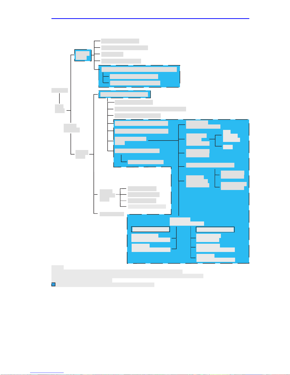
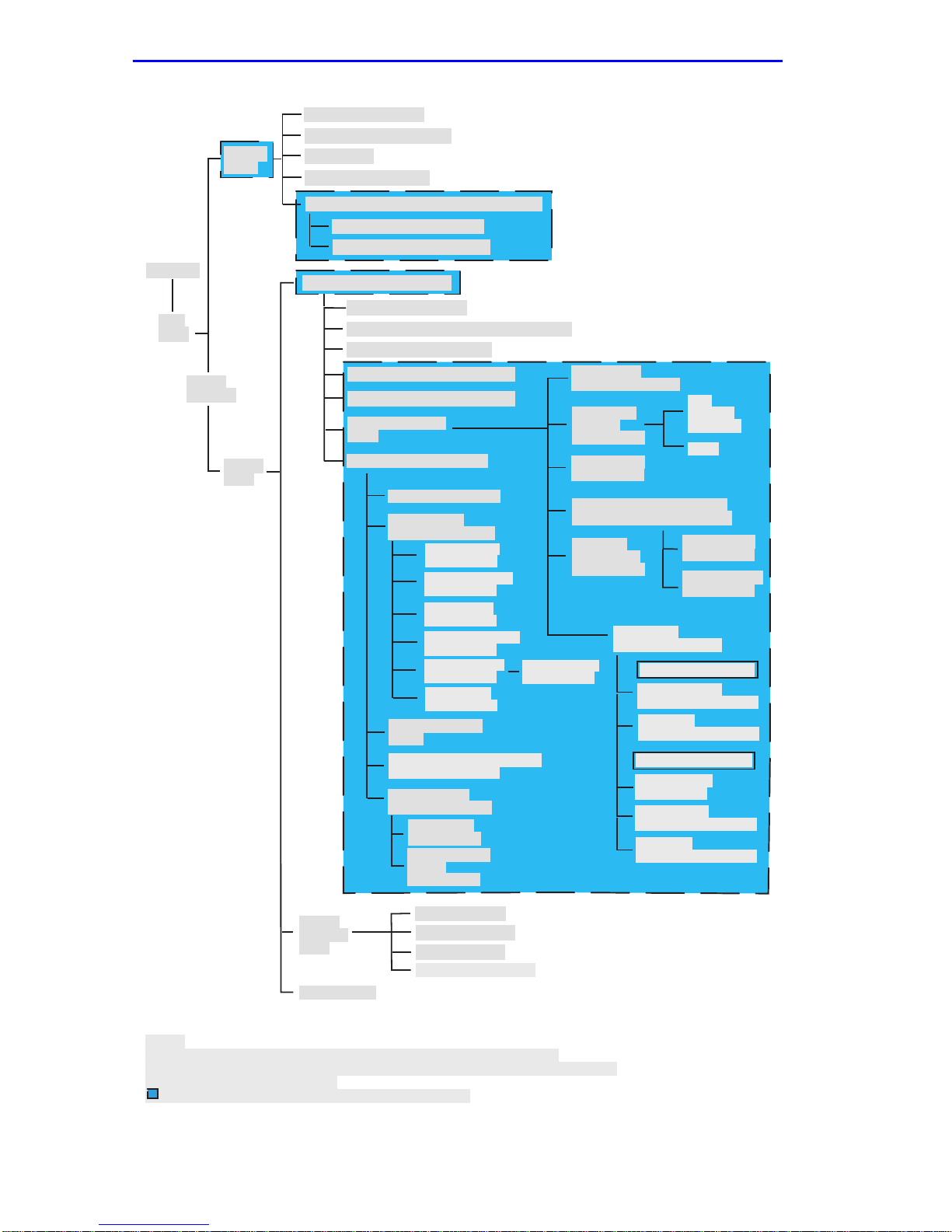
Depending on the Operational Mode set for the module, the hierarchy of
the Local Management screens differs as shown in Figure 1-1 and
Figure 1-2. Refer to the appropriate figure that relates to the Operational
Mode set for the module to see the applicable Local Management screen
hierarchy.
The areas that changed in the hierarchy are highlighted as
NOTE
shown in Figure 1-1 and Figure 1-2. The screens involved are
covered in this document. These screens may have been
added, changed, or have changed location in the
hierarchy.
1-2 Local Management Supplement
Accessing Local Management
\
Chassis Configuration
SNMP Community Names
Chassis
Menu
assword
Main
Menu
Module
Selection
Module
Menu
Notes:
Refer to the
SmartTrunk User's Guide
* This screen is only available on repeater devices (6E123-50, 6E133-49,
6H123-50, and 6H133-37).
Indicates the part of the hierarchy that changed.
SNMP Traps
Chassis Environmental
Port Redirect/Redirect Configuration Menu
Port Redirect Configuration
VLAN Redirect Configuration
Module Configuration Menu
General Configuration
SNMP Community Names Configuration
SNMP Traps Configuration
System Resources Information
Flash Download Configuration
Port Configuration
Menu
802.1 Configuration Menu
Switch Configuration
Module
Statistics
Menu
Network Tools
Switch Statistics
Interface Statistics
RMON Statistics
** Repeater Statistics
6E123-50/6E133-49 only
Repeater Level
Security Configuration
Port Level
Security Configuration
for the screen hierarchy.
Ethernet Full
Duplex Configuration
High Speed
Interface
Configuration
* SmartTrunk
Configuration
Port Redirect Configuration
Broadcast
Suppression
Configuration
** Repeater
Configuration Menu
6H123-50/6H133-37 only
Repeater Port
Configuration
Module Level
Security Configuration
Port Level
Security Configuration
Fast
Ethernet
Interfaces
HSIM
Port Redirect
Configuration
VLAN Redirect
Configuration
30262_82
Figure 1-1 802.1D Switching Mode, LM Screen Hierarchy
Local Management Supplement 1-3
Chapter 1:
Chassis
Menu
Password
Main
Menu
Module
Selection
Module
Menu
Changes to Local Management Screens
Chassis Configuration
SNMP Community Names
SNMP Traps
Chassis Environmental
Port Redirect/Redirect Configuration Menu
Port Redirect Configuration
VLAN Redirect Configuration
Module Configuration Menu
General Configuration
SNMP Community Names Configuration
SNMP Traps Configuration
System Resources Information
Flash Download Configuration
Port Configuration
Menu
802.1 Configuration Menu
Switch Configuration
802.1Q VLAN
Configuration Menu
Module/VLAN
Configuration
Port Assignment
Configuration
Port Filtering
Configuration
VLAN Forwarding
Configuration
Protocol VLAN
Configuration
IGMP/VLAN
Configuration
GARP Operation
Status
GMRP Group Registrations/
GMRP Confguration
802.1p Priority
ConfigurationMenu
Port Priority
Configuration
Advanced Port
Priority
Configuration
Protocol Ports
Configuration
Ethernet Full
Duplex Configuration
High Speed
Interface
Configuration
* SmartTrunk
Configuration
Port Redirect Configuration/
Redirect Configuration Menu
Broadcast
Suppression
Configuration
Fast
Ethernet
Interfaces
HSIM
Port Redirect
Configuration
VLAN Redirect
Configuration
** Repeater
Configuration Menu
6E123-50/6E133-49 only
Repeater Level
Security Configuration
Port Level
Security Configuration
6H123-50/6H133-37 only
Repeater Port
Configuration
Module Level
Security Configuration
Port Level
Security Configuration
Module
Statistics
Menu
Network Tools
Notes:
* Refer to the
SmartTrunk User's Guide
** This screen is only available on repeater devices (6E123-50, 6E133-49,
6H123-50, and 6H133-37).
Indicates the part of the hierarchy that changed.
Figure 1-2 802.1Q Switching Mode, LM Screen Hierarchy
1-4 Local Management Supplement
Switch Statistics
Interface Statistics
RMON Statistics
** Repeater Statistics
for the screen hierarchy.
30261_82
Accessing Local Management
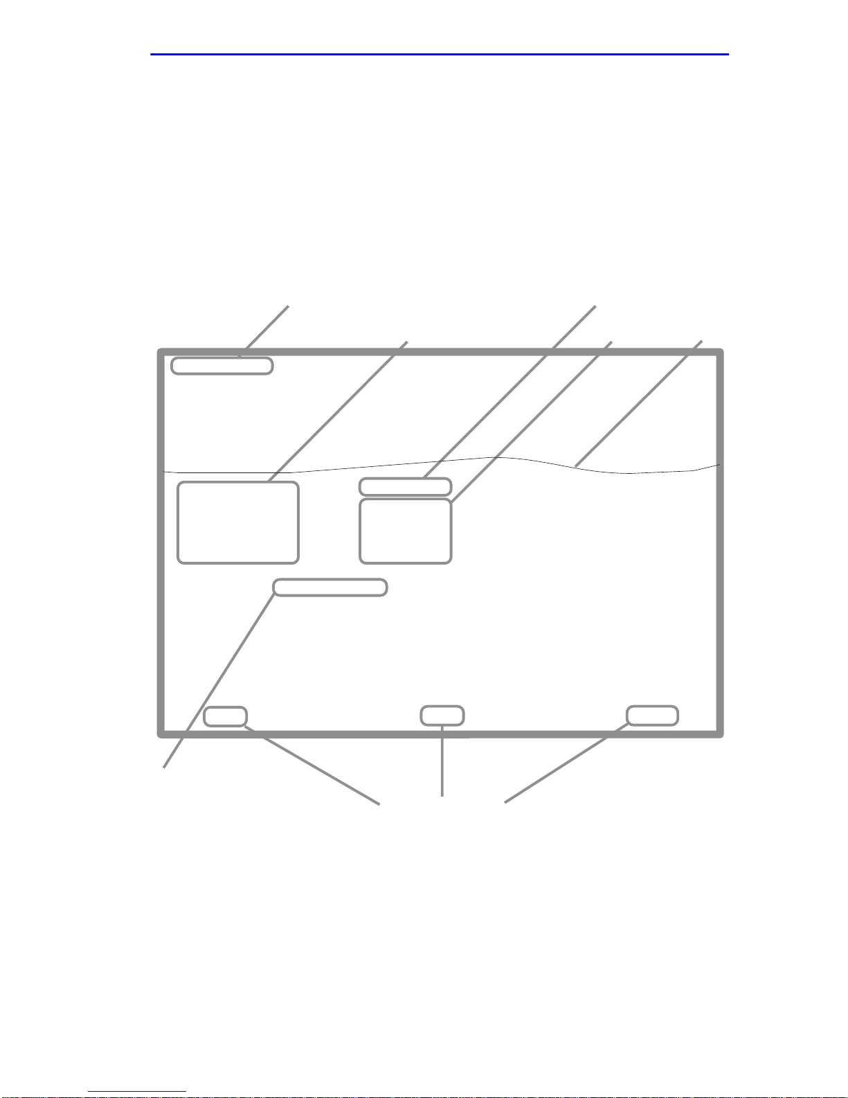
1.2.2 Screen Format
Since the top part of the screen contains the same type of information (the
name of the screen, the SmartSwitch model number, the firmware
revision, and the BOOT PROM revision), it is not shown in the following
descriptions of each screen. Only the fields in the lower portion of the
screens are shown. The name of the screen is in the figure title for each
screen. Figure 1-3 shows an example of the fields in a screen.
Event Message Field
Event Message Line
Device Type: 6xxxx-xx
MAC Address:
IP Address:
Subnet Mask:
Default Gateway:
TFTP Gateway IP Addr:
Operational Mode: [802.1Q SWITCHING]
Clear NVRAM [NO]
IP Fragmentation [ENABLED]
Display Fields
6xxxx-xx LOCAL MANAGEMENT
General Configuration
00-00-ID-00-00-00
0.0.0.0
255.255.0.0
NONE DEFINED
0.0.0.0
Display Field
Input Fields
Firmware Revision: XX.XX.XX
BOOTPROM Revision: XX.XX.XX
Device Date:
Device Time:
Screen Refresh Time:
Screen Lockout Time:
Device Uptime XX D XX H XX M
10/11/1999
14:23:00
30 sec.
15 min.
See
Note
Selection Field
Note:
This shows the location of the cutaway that is used in most of the screen graphics in this
document. The top portion of the screen is cut away to eliminate repeating the same
information in each graphic.The screen title is contained in the figure title for each screen.
Figure 1-3 Example of a Local Management Screen
Local Management Supplement 1-5
EXIT
Command Fields
RETURNSAVE
3026_14

Chapter 1:
Changes to Local Management Screens
1.3 CHASSIS MENU SCREEN (CHASSIS)
Section 1.3 through Section 1.6 provide information about the
NOTE
The Chassis Menu screen, Figure 1-4, provides access to Local
Management screens that allow you to configure and monitor operating
parameters, modify SNMP community names, set SNMP traps, monitor
the 6C105 environmental status, and to perform port redirect functions.
To access the Chassis Menu screen from the Main Menu screen, use the
arrow ke ys to highlight the
Chassis Menu screen displays.
chassis level screens and followed by the information
concerning the module level screens.
CHASSIS
menu item and press ENTER. The
CHASSIS CONFIGURATION
SNMP COMMUNITY NAMES
SNMP TRAPS
CHASSIS ENVIRONMENTAL
PORT REDIRECT
RETURN
3026_99
Figure 1-4 Chassis Menu Screen (Chassis)
The following briefly explains each screen accessible from the Chassis
Menu screen.
CHASSIS CONFIGURATION
Used to configure operating parameters for the 6C105 chassis. For details,
refer to your SmartSwitch user’s guide.
1-6 Local Management Supplement

Port Redirect/Redirect Configuration Menu Screen (Chassis)
SNMP COMMUNITY NAMES
Used to enter new, change, or review the community names used as
access passwords for module management operation. Access is limited
based on the password level of the user. For details, refer to your
SmartSwitch user’s guide.
SNMP TRAPS
Provides display and configuration access to the table of IP addresses
used for trap destinations and associated community names. For details,
refer to your SmartSwitch user’s guide.
CHASSIS ENVIRONMENTAL
Provides access to the chassis power supply status, power supply
redundancy status, and chassis fan tray status. For details, refer to your
SmartSwitch user’s guide.
PORT REDIRECT
Provides access to the Redirect Configuration Menu, which provides
access to the Port Redirect Configuration and VLAN Configuration
screens. For details, refer to Section 1.4.
1.4 PORT REDIRECT/REDIRECT CONFIGURATION
MENU SCREEN (CHASSIS)
The Redirect Configuration Menu screen displays only when
NOTE
The Redirect Configuration Menu screen (Figure 1-5) for the chassis
provides access to the Port Redirect Configuration and VLAN Redirect
Configuration screens. An y combination, up to 128, of port and/or VLAN
redirect instances can be configured per installed module, giving a
maximum of 640 instances for a chassis with 5 modules. Up to 24
instances per module can be configured as remote instances to other
modules in the chassis.
the operational mode of one or more of the modules in the
chassis are set to 802.1Q switching. If no modules in the
chassis are set to 802.1Q switching, the Redirect Configuration
Menu screen will display directly when the Port Redirect field is
selected, and the VLAN Redirect Configuration screen will not
be accessible.
Local Management Supplement 1-7

Chapter 1:
Changes to Local Management Screens
T o access the Redirect Configuration Menu screen from the Chassis Menu
screen, use the arrow keys to highlight the
PORT REDIRECT
menu
item and press ENTER. The Redirect Configuration Menu screen
displays.
PORT REDIRECT CONFIGURATION
VLAN REDIRECT CONFIGURATION
EXIT
Figure 1-5 Redirect Configuration Menu Screen (Chassis)
RETURN
3026_94
The following defines each selectable item of the Redirect Configuration
Menu screen:
PORT REDIRECT CONFIGURATION
Used to redirect traffic from a source switch port to a destination switch
port. The source and destination ports can be on different modules in the
chassis. For details, refer to Section 1.5.
VLAN REDIRECT CONFIGURATION
Used to configure the module to direct traffic from a VLAN to a particular
switch port across modules in the chassis. For details, refer to Section 1.6.
1-8 Local Management Supplement

Port Redirect Configuration Screen (Chassis)
1.5 PORT REDIRECT CONFIGURATION SCREEN
(CHASSIS)
The Port Redirect Configuration screen, Figure 1-6, enables the user to
select a source module and port as well as a destination module and port
and add a new Port Redirect or delete an existing one. Source and
destination ports can only be used in one redirect instance, and only
installed and capable modules and ports will appear in the selectable
fields. If a port is currently being redirected, it does not appear in the
source or destination selectable fields. Frames received on the source port
can be redirected in a particular frame format, and any frames with errors
can be either dropped or forwarded to the destination port. For example,
port 1 can be set as the source port with port 2 as the destination port.
Frames from port 1 are then automatically redirected to port 2 according
to a particular frame format, and frames with errors can be either
forwarded or dropped according to the screen settings.
The port redirect function is extremely useful for troubleshooting
purposes, as it allows traf fic to be sent to a particular port where, with the
use of an analyzer or RMON probe, all current traffic from the source port
can be examined.
Although all traffic from the source port (including, if desired,
NOTE
errored frames) is sent to the destination port, normal s witching
is still performed for all frames on the source port.
To access the Port Redirect Configuration screen from the Port Redirect
screen, use the arrow keys to highlight the PORT REDIRECT
CONFIGURATION menu item and press ENTER.
Local Management Supplement 1-9

Chapter 1: Changes to Local Management Screens
Source
----------------------
Module Port
1 1
1 2
1 3
1 4
1 5
1 6
1 7
1 8
Src Port [ 2 ]
Src Module [ 1 ]
SAVE
Destination
------------------------ --------------------
Module Port
2 1
2 2
2 3
2 4
2 5
2 6
2 7
2 8
Frame Format [UNTAGGED]Dest Port [ 16 ]
Dest Module [ 2 ]
PREVIOUS NEXT
Remap Errors [OFF]
FrameFormat
NORMAL
TAGGED
UNTAGGED
NORMAL
NORMAL
NORMAL
NORMAL
NORMAL
Remap Errors
--------------------
ON
ON
ON
ON
ON
ON
ON
ON
EXIT
Status [DELETE]
RETURN
RETURN
3026_26
Figure 1-6 Port Redirect Configuration Screen (Chassis)
The following definitions briefly explain each field of the Port Redirect
Configuration screen:
Source Module (Read-Only)
Shows which modules are currently set as source modules.
Source Port (Read-only)
Shows which ports are currently set as source ports.
Destination Module (Read-Only)
Shows which modules are currently set as destination modules.
Destination Port (Read-only)
Shows which ports are currently set as destination ports. Only one
destination port may be assigned to a source port.
1-10 Local Management Supplement

Port Redirect Configuration Screen (Chassis)
Frame Format (Read-Only)
Displays the current frame format setting: NORMAL, TAGGED or
UNTAGGED. The default is NORMAL.
• NORMAL – Frames are redirected in the format that they were
received or transmitted on the source port.
• TAGGED – Frames are transmitted on the destination port with a
VLAN tag inserted according to the frame classification.
• UNT A GGED – Frames are transmitted on the destination port without
a VLAN tag regardless of the format of the received frame.
Remap Errors (Read-Only)
Displays whether the corresponding source ports are configured ON to
send errored frames to the destination ports, or OFF to drop all errored
frames and only forward traffic without errored frames to the destination
ports. All redirected error frames display in the way the y were recei v ed or
transmitted on the source port, regardless of the frame format setting.
Refer to Section 1.15.1 for directions on how to change the
NOTE
Src Port [n] (Selectable)
settings for the following fields.
Used to select the port [n] that is to be changed to a source port. If a port
is currently being redirected, it will not display as a selectable port.
Src Module [n] (Selectable)
Used to select the module [n] that is to be changed to a source module.
Dest Port [n] (Selectable)
Used to select the port [n] that is to be changed to a destination port. If a
port is currently being redirected, it will not display as a selectable port.
Dest Module [n] (Selectable)
Used to select the module [n] that is to be changed to a destination
module.
Local Management Supplement 1-11

Chapter 1: Changes to Local Management Screens
Frame Format (Selectable)
Used to select the frame format for the transmission of redirected frames
on the destination port. NORMAL, TAGGED, or UNTAGGED may be
selected. Refer to the previously described read-only Frame Format field
for details about each format. The default setting is NORMAL.
Remap Errors (Toggle)
Used to set each source port to either ON, to send errored frames to its
destination port, or OFF to drop errored frames, and send only valid
traffic to its destination port. The default setting is OFF.
Status (Toggle)
Used to add or delete source and destination ports selected in the Source
Port [n] and Destination Port [n] fields.
1.5.1 Changing Source and Destination Ports
To add or delete source port and destination port entries and set the Frame
Format and Redirect Errors functions, proceed as follows:
1. Use the arrow keys to highlight the Src Port field near the bottom of
the screen.
2. Press the SPACE bar or BACKSPACE one or more times to increment
or decrement the port number displayed in the brackets [n] until the
appropriate port number displays.
3. Use the arrow keys to highlight the Src Module field near the bottom
of the screen.
4. Use the SPACE bar or BACKSPACE to step to the appropriate
module number for the source module.
5. Use the arrow keys to highlight the Dest Port field near the bottom of
the screen.
6. Press the SPACE bar or BACKSPACE one or more times to increment
or decrement the port number displayed in the brackets [n] until the
appropriate port number displays.
7. Use the arrow keys to highlight the Dest Module field near the bottom
of the screen.
8. Use the SPACE bar or BACKSPACE to step to the appropriate
module number for the destination module.
1-12 Local Management Supplement
 Loading...