

Page 1

SmartSwitch 6500 User Guide
35 Industrial Way
Rochester, NH 03866
USA
(603) 332-9400
Part Number 04-0050-01 Rev. A
Order Number 9032706
Page 2

NOTICE
Cabletron Systems reserves the right to make changes in specifications and other information contained in this
document without prior notice. The reader should in all cases consult Cabletron Systems to determine whether any
such changes have been made. The hardware, firmware, and software described in this manual are subject to change
without notice.
IN NO EVENT SHALL CABLETRON SYSTEMS BE LIABLE FOR ANY INCIDENT AL, INDIRECT, SPECIAL,
OR CONSEQUENTIAL DAMAGES WHATSOEVER (INCLUDING, BUT NOT LIMITED TO, LOST PROFITS)
ARISING OUT OF OR RELATED TO THIS MANUAL OR THE INFORMATION CONTAINED IN IT, EVEN IF
CABLETRON SYSTEMS HAS BEEN ADVISED OF, KNOWN, OR SHOULD HAVE KNOWN, THE
POSSIBILITY OF SUCH DAMAGES.
Copyright 1998 - 99 by Cabletron Systems, Inc., P.O. Box 5005, Rochester, NH 03866-5005
All Rights Reserved
Printed in the United States of America
SmartSwitch 6500 User Guide
Part Number 04-0050-01 Rev. A
Order Number: 9032706
SmartSwitch, SPECTRUM, LANVIEW, MicroMMAC, and BRIM are registered trademarks and Element Manager,
EPIM, EPIMA, EPIM-F1, EPIM-F2, EPIM-F3, EPIM-T, EPIM-X, FOT-F, FOT-F3, HubSTACK, SEH, SEHI, and
TMS-3 are tradem arks of Cabletr on Systems, Inc . All other product names mentioned in this manual may be
trademarks or registered trademarks of their respective companies.
ii SmartSwitch 6500 User Guide
Page 3

FCC CLASS A NOTICE
This device complies with Part 15 of the FCC rules. Operation is subject to the following two conditions: (1) this
device may not cause harmful interference, and (2) this device must accept any interference received, including
interference that may cause undesired operation.
Note This equipment has been tested and found to comply with the limits for a Class A
digital device, pursuant to Part 15 of the FCC rules. These limits are designed to
provide reasonable protection against harmful interference when the equipment is
operated in a commercial environment. This equipment uses, generates, and can
radiate radio frequency energy and if not installed in accordance with the
SmartSwitch 6500 User Guide, may cause harmful interference to radio
communications. Operation of this equipment in a residential area is likely to
cause interference in which case the user will be required to correct the
interference at his own expense.
Caution Changes or modifications made to this device which are not expr essly approved
by the party responsible for compliance could void the user’s authority to
operate the equipment.
DOC CLASS A NOTICE
This digital apparatus does not exceed the Class A limits for radio noise emissions from digital apparatus set out in the
Radio Interference Regulations of the Canadian Department of Communications.
Le present appareil numerique n’emet pas de bruits radioelectriques depassant les limites applicables aux appareils
numeriques de la class A prescrites dans le Reglement sur le brou illage radioelectrique edicte par le ministere des
Communications du Canada.
SmartSwitch 6500 User Guide iii
Page 4

DECLARATION OF CONFORMITY
ADDENDUM
Application of Council Directive(s):
89/336/EEC
73/23/EEC
Manufacturer’s Name:
Manufacturer’s Address:
Product Name:
European Representative Name:
European Representative Address:
Conformance to Directive(s)/Product Standards:
Equipment Type/Environment:
Cabletron Systems, Inc.
35 Industrial Way
P. O. Box 5005
Rochester, NH 03866
SmartSwitch 6500
Mr. J. Solari
Cabletron Systems, Limited
Nexus House, Newbury Business Park
London Road, Newbury
Berkshire RG13 2PZ, England
EC Directive 89/336/EEC
EC Directive 73/23/EEC
EN 55022
EN 50082-1
EN 60950
Networking Equipment, for use in a Commerci al or Light
Industrial Environment.
We the undersigned, hereby declare, under our sole respo nsi bility, that the equipment packa ged with this
notice conforms to the above directives.
Manufacturer:
Legal Repersentative in Europe:
iv SmartSwitch 6500 User Guide
Full Name:
Title:
Location:
Full Name:
Title:
Location:
Mr. Ronald Fotino
Principal Compliance Engineer
Rochester, NH. U.S.A.
Mr. J. Solari
Managing Director - E.M.E.A.
Newbury, Berkshire, England
Page 5

SAFETY INFORMATION
CLASS 1 LASER TRANSCEIVERS
The IOM-29-4, IOM-29-4-IR, IOM-29-4-LR, IOM-39 -1 and IOM-39-1-LR connectors use Class 1 Laser transceivers.
Read the following safety information before installing or operatin g one of these modules.
The Class 1 Laser transceivers use an optical feedback loop to main tain Class 1 operation limits. This control loop
eliminates the need for maintenance checks or adjustments. The output is factory set, and does not allow any user
adjustment. Class 1 Laser transceivers comply with the following safety standards:
•
21 CFR 1040.10 and 1040.11 U. S. Department of Health and Human Services (FDA).
•
IEC Publication 825 (International Electrotechnical Commission).
•
CENELEC EN 60825 (European Committee for Electrotechnical Standardization).
When operating within their performance limitations, laser transceiver output meets the Class 1 accessible emission
limit of all three standards. Class 1 levels of laser radiation are not considered hazardous.
LASER RADIATION AND CONNECTORS
When the connector is in place, all laser radiation remains within the fiber. The maximum amount of radiant power
exiting the fiber (under normal conditions) is -12.6dBm or 55x10
Removing the optical connector from the transceiver a llows laser r adiation to emit d irectly f rom the o ptical po rt. Th e
maximum radiance from the optical port (under worst case conditions) is 0.8 W cm
Do not use optical instruments to view the laser output. The use of optical instruments to view laser output increases
eye hazard. When viewing the output optical port, you must remove power from the network adapter.
-6
watts.
-2
or 8x10³ W m-2 sr-1.
SmartSwitch 6500 User Guide v
Page 6

FIBER OPTIC PROTECTIVE CAPS
Warning READ BEFORE REMOVING FIBER OPTIC PROTECTIVE CAPS.
Cable assemblies and MMF/SMF ports are shipped with protective caps to prevent contamination. To avoid
contamination, replace port caps on all fiber optic devices when not in use.
Cable assemblies and MMF/SMF ports that become contaminated may experience signal loss or difficulty inserting
and removing cable assemblies from MMF/SMF ports.
Contamination can be removed from cable assemblies by:
1. Blowing surfaces with canned duster (Chemtronics p/n ES1270 or equivalent).
2. Using a fiber port cleaning swab (Alcoa Fujikura LTS p/n ACT-01 or equivalent) saturated with
optical-grade isopropyl alcohol, gently wipe the end surface of ferrules first; then wipe down the
sides of both ferrules.
3. Blow ferrule surfaces dry with canned duster.
Contamination can be removed from MMF/SMF ports by:
1. Using the extension tube supplied with canned duster, blow into the optical port, being careful not
to allow the extension tube to touch the bottom of the optical port.
2. R econnect cable and check f or proper mating. If pr oblems remain, gently wipe out optical port with
a DRY fiber port cleaning swab and repeat step 1.
Warning T o avoid contamination, replace port caps on all fiber optic devices when not
in use.
vi SmartSwitch 6500 User Guide
Page 7

REGULATORY COMPLIANCE SUMMARY
SAFETY
The SmartSwitch 6500 meets the safety requirements of UL 1950, CSA C22.2 No. 950, EN 60950, IEC 950, and
73/23/EEC.
EMC
The SmartSwitch 6500 meet s th e EMC requirements of FCC Part 15 , EN 55022, CSA C108.8, VCCI V-3 /9 3.0 1, EN
50082-1, and 89/336/EEC.
SmartSwitch 6500 User Guide vii
Page 8

REVISION HISTORY
Document Name: SmartSwitch 6500 Us er Guide
Document Part Number: 04-0050-01 Rev. A
Document Order Number: 9032706
Author: Bruce Jordan
Editor: Carre Gibson
Illustrator: Mike Fornalski
Date Revision Description
#VÍœLiÀÊ£™™n " Initial release
viii SmartSwitch 6500 User Guide
Page 9

Table of Contents
TABLE OF CONTENTS
1 Introducing the SmartSwitch 6500 . . . . . . . . . . . . . . . . . . . . . . . . . . . . . . . . 1-1
1.1 SmartSwitch 6500 Modules . . . . . . . . . . . . . . . . . . . . . . . . . . . . . . . . . . . . . . . . . . . . . . . . . . . . . . . . . 1-2
1.1.1 Cell Storage Module (CSM) . . . . . . . . . . . . . . . . . . . . . . . . . . . . . . . . . . . . . . . . . . . . . . . . . . . . . 1-2
1.1.2 Translation and Scheduling Module (TSM) . . . . . . . . . . . . . . . . . . . . . . . . . . . . . . . . . . . . . . . . . 1-2
1.1.3 CPU Module . . . . . . . . . . . . . . . . . . . . . . . . . . . . . . . . . . . . . . . . . . . . . . . . . . . . . . . . . . . . . . . . . 1-2
1.1.4 Input/Output Modules (IOMs). . . . . . . . . . . . . . . . . . . . . . . . . . . . . . . . . . . . . . . . . . . . . . . . . . . . 1-3
2 Switch Installation and Setup. . . . . . . . . . . . . . . . . . . . . . . . . . . . . . . . . . . . 2-1
2.1 Receiving the SmartSwitch 6500 . . . . . . . . . . . . . . . . . . . . . . . . . . . . . . . . . . . . . . . . . . . . . . . . . . . . . 2-1
2.1.1 Inspecting the Order. . . . . . . . . . . . . . . . . . . . . . . . . . . . . . . . . . . . . . . . . . . . . . . . . . . . . . . . . . . . 2-1
2.1.2 Unpacking . . . . . . . . . . . . . . . . . . . . . . . . . . . . . . . . . . . . . . . . . . . . . . . . . . . . . . . . . . . . . . . . . . . 2-3
2.1.3 Check Accessory Carton Contents. . . . . . . . . . . . . . . . . . . . . . . . . . . . . . . . . . . . . . . . . . . . . . . . .2-4
2.2 Switch Installation and Assembly. . . . . . . . . . . . . . . . . . . . . . . . . . . . . . . . . . . . . . . . . . . . . . . . . . . . . 2-5
2.2.1 Mounting the Chassis. . . . . . . . . . . . . . . . . . . . . . . . . . . . . . . . . . . . . . . . . . . . . . . . . . . . . . . . . . . 2-5
2.2.2 Installing The Power Supplies . . . . . . . . . . . . . . . . . . . . . . . . . . . . . . . . . . . . . . . . . . . . . . . . . . . . 2-5
2.2.3 Installing the CSM . . . . . . . . . . . . . . . . . . . . . . . . . . . . . . . . . . . . . . . . . . . . . . . . . . . . . . . . . . . . . 2-7
2.2.4 Installing the TSM with CPU Daughter Board . . . . . . . . . . . . . . . . . . . . . . . . . . . . . . . . . . . . . . . 2-9
2.2.5 Installing Additional TSM Modules . . . . . . . . . . . . . . . . . . . . . . . . . . . . . . . . . . . . . . . . . . . . . . 2-11
2.2.6 Installing Other Modules in the SmartSwitch 6500 Chassis . . . . . . . . . . . . . . . . . . . . . . . . . . . . 2-11
2.3 Configuring the Switch. . . . . . . . . . . . . . . . . . . . . . . . . . . . . . . . . . . . . . . . . . . . . . . . . . . . . . . . . . . . 2-13
2.3.1 Initial Network Configuration . . . . . . . . . . . . . . . . . . . . . . . . . . . . . . . . . . . . . . . . . . . . . . . . . . . 2-13
2.3.2 Backup/Redundancy Configuration. . . . . . . . . . . . . . . . . . . . . . . . . . . . . . . . . . . . . . . . . . . . . . .2-16
2.4 LED Descriptions . . . . . . . . . . . . . . . . . . . . . . . . . . . . . . . . . . . . . . . . . . . . . . . . . . . . . . . . . . . . . . . .2-19
2.5 Using the Console. . . . . . . . . . . . . . . . . . . . . . . . . . . . . . . . . . . . . . . . . . . . . . . . . . . . . . . . . . . . . . . . 2-20
2.5.1 Port Numbering . . . . . . . . . . . . . . . . . . . . . . . . . . . . . . . . . . . . . . . . . . . . . . . . . . . . . . . . . . . . . . 2-20
2.5.2 Console Commands . . . . . . . . . . . . . . . . . . . . . . . . . . . . . . . . . . . . . . . . . . . . . . . . . . . . . . . . . . .2-21
2.5.3 Console Time-out. . . . . . . . . . . . . . . . . . . . . . . . . . . . . . . . . . . . . . . . . . . . . . . . . . . . . . . . . . . . . 2-23
2.5.4 Creating an Alias . . . . . . . . . . . . . . . . . . . . . . . . . . . . . . . . . . . . . . . . . . . . . . . . . . . . . . . . . . . . . 2-23
2.5.5 Ambiguous Commands . . . . . . . . . . . . . . . . . . . . . . . . . . . . . . . . . . . . . . . . . . . . . . . . . . . . . . . . 2-23
2.5.6 Console Help . . . . . . . . . . . . . . . . . . . . . . . . . . . . . . . . . . . . . . . . . . . . . . . . . . . . . . . . . . . . . . . . 2-24
2.6 SmartSwitch ATM Administrator. . . . . . . . . . . . . . . . . . . . . . . . . . . . . . . . . . . . . . . . . . . . . . . . . . . . 2-25
2.6.1 PC Installation . . . . . . . . . . . . . . . . . . . . . . . . . . . . . . . . . . . . . . . . . . . . . . . . . . . . . . . . . . . . . . . 2-27
2.6.2 Solaris Workstation Installation. . . . . . . . . . . . . . . . . . . . . . . . . . . . . . . . . . . . . . . . . . . . . . . . . . 2-27
2.6.3 Starting SmartSwitch ATM Administrator . . . . . . . . . . . . . . . . . . . . . . . . . . . . . . . . . . . . . . . . . 2-27
2.6.4 Initial SmartSwitch ATM Administrator Set Up. . . . . . . . . . . . . . . . . . . . . . . . . . . . . . . . . . . . . 2-27
2.6.5 Default Community Strings. . . . . . . . . . . . . . . . . . . . . . . . . . . . . . . . . . . . . . . . . . . . . . . . . . . . . 2-28
2.6.6 Accessing Online Help. . . . . . . . . . . . . . . . . . . . . . . . . . . . . . . . . . . . . . . . . . . . . . . . . . . . . . . . . 2-28
3 IP Over ATM and LANE. . . . . . . . . . . . . . . . . . . . . . . . . . . . . . . . . . . . . . . . 3-1
3.1 Creating an IP over ATM VLAN . . . . . . . . . . . . . . . . . . . . . . . . . . . . . . . . . . . . . . . . . . . . . . . . . . . . . 3-1
3.1.1 Default ATM Addressing for IP over ATM . . . . . . . . . . . . . . . . . . . . . . . . . . . . . . . . . . . . . . . . . 3-3
SmartSwitch 6500 User Guide ix
Page 10

Table of Contents
3.2 Creating an Emulated LAN. . . . . . . . . . . . . . . . . . . . . . . . . . . . . . . . . . . . . . . . . . . . . . . . . . . . . . . . . .3-3
3.2.1 ATM Addressing for LAN Emulation . . . . . . . . . . . . . . . . . . . . . . . . . . . . . . . . . . . . . . . . . . . . . .3-6
3.2.2 ELANs Across Multiple Switches . . . . . . . . . . . . . . . . . . . . . . . . . . . . . . . . . . . . . . . . . . . . . . . . .3-7
3.2.3 Switch Clients. . . . . . . . . . . . . . . . . . . . . . . . . . . . . . . . . . . . . . . . . . . . . . . . . . . . . . . . . . . . . . . . .3-7
3.2.4 Distributed LANE Services . . . . . . . . . . . . . . . . . . . . . . . . . . . . . . . . . . . . . . . . . . . . . . . . . . . . . .3-8
3.2.5 ELAN Join Policies . . . . . . . . . . . . . . . . . . . . . . . . . . . . . . . . . . . . . . . . . . . . . . . . . . . . . . . . . . . .3-9
4 PNNI Routing . . . . . . . . . . . . . . . . . . . . . . . . . . . . . . . . . . . . . . . . . . . . . . . .4-1
4.1 PNNI Node Addressing. . . . . . . . . . . . . . . . . . . . . . . . . . . . . . . . . . . . . . . . . . . . . . . . . . . . . . . . . . . . .4-1
4.2 Multi-level PNNI Topology . . . . . . . . . . . . . . . . . . . . . . . . . . . . . . . . . . . . . . . . . . . . . . . . . . . . . . . . .4-2
4.2.1 Connecting Multiple Peer Groups . . . . . . . . . . . . . . . . . . . . . . . . . . . . . . . . . . . . . . . . . . . . . . . . .4-2
4.2.2 Physical Connections Between Peer Groups . . . . . . . . . . . . . . . . . . . . . . . . . . . . . . . . . . . . . . . . . 4-6
4.3 Managing Parallel PNNI Links . . . . . . . . . . . . . . . . . . . . . . . . . . . . . . . . . . . . . . . . . . . . . . . . . . . . . . .4-8
4.3.1 Aggregation Tokens. . . . . . . . . . . . . . . . . . . . . . . . . . . . . . . . . . . . . . . . . . . . . . . . . . . . . . . . . . . .4-9
5 Routing . . . . . . . . . . . . . . . . . . . . . . . . . . . . . . . . . . . . . . . . . . . . . . . . . . . . .5-1
5.1 Additional Routing Protocols . . . . . . . . . . . . . . . . . . . . . . . . . . . . . . . . . . . . . . . . . . . . . . . . . . . . . . . .5-1
5.2 IISP Routes . . . . . . . . . . . . . . . . . . . . . . . . . . . . . . . . . . . . . . . . . . . . . . . . . . . . . . . . . . . . . . . . . . . . . .5-1
5.2.1 IISP Routing Considerations . . . . . . . . . . . . . . . . . . . . . . . . . . . . . . . . . . . . . . . . . . . . . . . . . . . . .5-2
5.3 UNI Routes . . . . . . . . . . . . . . . . . . . . . . . . . . . . . . . . . . . . . . . . . . . . . . . . . . . . . . . . . . . . . . . . . . . . . .5-4
5.4 Route Metrics. . . . . . . . . . . . . . . . . . . . . . . . . . . . . . . . . . . . . . . . . . . . . . . . . . . . . . . . . . . . . . . . . . . . .5-5
5.5 IP Routing . . . . . . . . . . . . . . . . . . . . . . . . . . . . . . . . . . . . . . . . . . . . . . . . . . . . . . . . . . . . . . . . . . . . . . .5-6
6 Virtual Ports and Static Connections. . . . . . . . . . . . . . . . . . . . . . . . . . . . . . .6-1
6.1 PVC Connections . . . . . . . . . . . . . . . . . . . . . . . . . . . . . . . . . . . . . . . . . . . . . . . . . . . . . . . . . . . . . . . . .6-1
6.1.1 Point-to-Point PVCs. . . . . . . . . . . . . . . . . . . . . . . . . . . . . . . . . . . . . . . . . . . . . . . . . . . . . . . . . . . .6-1
6.1.2 Point-to-Multipoint PVCs . . . . . . . . . . . . . . . . . . . . . . . . . . . . . . . . . . . . . . . . . . . . . . . . . . . . . . .6 -2
6.1.3 Connecting to Local Switch Client Through a PVC . . . . . . . . . . . . . . . . . . . . . . . . . . . . . . . . . . .6-4
6.2 PVP Connections. . . . . . . . . . . . . . . . . . . . . . . . . . . . . . . . . . . . . . . . . . . . . . . . . . . . . . . . . . . . . . . . . .6-4
6.2.1 Connecting PVPs . . . . . . . . . . . . . . . . . . . . . . . . . . . . . . . . . . . . . . . . . . . . . . . . . . . . . . . . . . . . . .6-6
6.3 Virtual Ports. . . . . . . . . . . . . . . . . . . . . . . . . . . . . . . . . . . . . . . . . . . . . . . . . . . . . . . . . . . . . . . . . . . . . .6-7
6.3.1 Creating Virtual Ports. . . . . . . . . . . . . . . . . . . . . . . . . . . . . . . . . . . . . . . . . . . . . . . . . . . . . . . . . . .6-7
7 Traffic Management . . . . . . . . . . . . . . . . . . . . . . . . . . . . . . . . . . . . . . . . . . .7-1
7.1 Traffic Management Capabilities . . . . . . . . . . . . . . . . . . . . . . . . . . . . . . . . . . . . . . . . . . . . . . . . . . . . .7-1
7.1.1 Traffic Descriptors . . . . . . . . . . . . . . . . . . . . . . . . . . . . . . . . . . . . . . . . . . . . . . . . . . . . . . . . . . . . .7-1
7.1.2 Call Admission Control Policy. . . . . . . . . . . . . . . . . . . . . . . . . . . . . . . . . . . . . . . . . . . . . . . . . . . .7-3
7.1.3 Queue Buffers. . . . . . . . . . . . . . . . . . . . . . . . . . . . . . . . . . . . . . . . . . . . . . . . . . . . . . . . . . . . . . . . .7-5
7.1.4 EFCI, EPD, and RM Cell Marking . . . . . . . . . . . . . . . . . . . . . . . . . . . . . . . . . . . . . . . . . . . . . . . .7-7
8 Upgrades and Firmware . . . . . . . . . . . . . . . . . . . . . . . . . . . . . . . . . . . . . . . .8-1
8.1 Upgrading and Changing Firmware . . . . . . . . . . . . . . . . . . . . . . . . . . . . . . . . . . . . . . . . . . . . . . . . . . .8-1
8.1.1 Accessing the Boot Load Prompt. . . . . . . . . . . . . . . . . . . . . . . . . . . . . . . . . . . . . . . . . . . . . . . . . .8-1
8.1.2 Boot Load Commands . . . . . . . . . . . . . . . . . . . . . . . . . . . . . . . . . . . . . . . . . . . . . . . . . . . . . . . . . .8-2
8.1.3 Upgrading Boot Load firmware. . . . . . . . . . . . . . . . . . . . . . . . . . . . . . . . . . . . . . . . . . . . . . . . . . .8-4
x SmartSwitch 6500 User Guide
Page 11

Table of Contents
8.1.4 Upgrading POST Diagnostic firmware . . . . . . . . . . . . . . . . . . . . . . . . . . . . . . . . . . . . . . . . . . . . .8-5
8.1.5 Upgrading Switch Operating firmware . . . . . . . . . . . . . . . . . . . . . . . . . . . . . . . . . . . . . . . . . . . . . 8-6
8.1.6 Using the Update Firmware Command . . . . . . . . . . . . . . . . . . . . . . . . . . . . . . . . . . . . . . . . . . . . . 8-7
9 Troubleshooting . . . . . . . . . . . . . . . . . . . . . . . . . . . . . . . . . . . . . . . . . . . . . . 9-1
9.1 Troubleshooting IP over ATM . . . . . . . . . . . . . . . . . . . . . . . . . . . . . . . . . . . . . . . . . . . . . . . . . . . . . . . 9-1
9.2 Troubleshooting LAN Emulation . . . . . . . . . . . . . . . . . . . . . . . . . . . . . . . . . . . . . . . . . . . . . . . . . . . . . 9-2
9.3 Troubleshooting PNNI Links . . . . . . . . . . . . . . . . . . . . . . . . . . . . . . . . . . . . . . . . . . . . . . . . . . . . . . . . 9-3
9.3.1 Switches in Same Peer Group . . . . . . . . . . . . . . . . . . . . . . . . . . . . . . . . . . . . . . . . . . . . . . . . . . . . 9-3
9.3.2 Switches in Different Peer Groups. . . . . . . . . . . . . . . . . . . . . . . . . . . . . . . . . . . . . . . . . . . . . . . . . 9-3
9.4 Troubleshooting Congestion. . . . . . . . . . . . . . . . . . . . . . . . . . . . . . . . . . . . . . . . . . . . . . . . . . . . . . . . . 9-4
9.4.1 Diagnosing Congestion . . . . . . . . . . . . . . . . . . . . . . . . . . . . . . . . . . . . . . . . . . . . . . . . . . . . . . . . . 9-4
9.4.2 Global Congestion . . . . . . . . . . . . . . . . . . . . . . . . . . . . . . . . . . . . . . . . . . . . . . . . . . . . . . . . . . . . . 9-4
9.4.3 Port Congestion . . . . . . . . . . . . . . . . . . . . . . . . . . . . . . . . . . . . . . . . . . . . . . . . . . . . . . . . . . . . . . . 9-5
9.5 Events and Alarms . . . . . . . . . . . . . . . . . . . . . . . . . . . . . . . . . . . . . . . . . . . . . . . . . . . . . . . . . . . . . . . . 9-6
9.5.1 Event Categories . . . . . . . . . . . . . . . . . . . . . . . . . . . . . . . . . . . . . . . . . . . . . . . . . . . . . . . . . . . . . . 9-6
9.5.2 Viewing Events and Alarms . . . . . . . . . . . . . . . . . . . . . . . . . . . . . . . . . . . . . . . . . . . . . . . . . . . . . 9-7
9.5.3 Deleting Events and Alarms . . . . . . . . . . . . . . . . . . . . . . . . . . . . . . . . . . . . . . . . . . . . . . . . . . . . . 9-8
9.6 Saving Core Dumps . . . . . . . . . . . . . . . . . . . . . . . . . . . . . . . . . . . . . . . . . . . . . . . . . . . . . . . . . . . . . . . 9-9
A Specifications. . . . . . . . . . . . . . . . . . . . . . . . . . . . . . . . . . . . . . . . . . . . . . . .A-1
B Agent Support . . . . . . . . . . . . . . . . . . . . . . . . . . . . . . . . . . . . . . . . . . . . . . .B-1
B.1 MIB, SMI, MIB Files and Internet MIB Hierarchy . . . . . . . . . . . . . . . . . . . . . . . . . . . . . . . . . . . . . . . B-1
B.1.1 ZeitNet Cabletron Proprietary MIBs . . . . . . . . . . . . . . . . . . . . . . . . . . . . . . . . . . . . . . . . . . . . . . .B-2
B.1.2 Relation Between Object Identifier and the Represented Value . . . . . . . . . . . . . . . . . . . . . . . . . .B -3
B.1.3 Supported protocols. . . . . . . . . . . . . . . . . . . . . . . . . . . . . . . . . . . . . . . . . . . . . . . . . . . . . . . . . . . .B-4
B.1.4 Supported SMI Formats. . . . . . . . . . . . . . . . . . . . . . . . . . . . . . . . . . . . . . . . . . . . . . . . . . . . . . . . .B-4
B.1.5 Zeitnet Cabletron Proprietary MIB Groups. . . . . . . . . . . . . . . . . . . . . . . . . . . . . . . . . . . . . . . . . .B-4
B.1.6 SmartSwitch 6500 MIB Support . . . . . . . . . . . . . . . . . . . . . . . . . . . . . . . . . . . . . . . . . . . . . . . . . .B-6
B.1.7 MIB Exceptions . . . . . . . . . . . . . . . . . . . . . . . . . . . . . . . . . . . . . . . . . . . . . . . . . . . . . . . . . . . . . . . B -6
B.2 Managing the SmartSwitch 6500 . . . . . . . . . . . . . . . . . . . . . . . . . . . . . . . . . . . . . . . . . . . . . . . . . . . . .B-7
B.2.1 Console Commands that Affect the Agent . . . . . . . . . . . . . . . . . . . . . . . . . . . . . . . . . . . . . . . . . .B-7
B.2.2 Default Community Strings. . . . . . . . . . . . . . . . . . . . . . . . . . . . . . . . . . . . . . . . . . . . . . . . . . . . . .B-8
C Technical Support . . . . . . . . . . . . . . . . . . . . . . . . . . . . . . . . . . . . . . . . . . . .C-1
C.1 Telephone Assistance . . . . . . . . . . . . . . . . . . . . . . . . . . . . . . . . . . . . . . . . . . . . . . . . . . . . . . . . . . . . . .C-1
C.2 FAX Service . . . . . . . . . . . . . . . . . . . . . . . . . . . . . . . . . . . . . . . . . . . . . . . . . . . . . . . . . . . . . . . . . . . . .C-1
C.3 Electronic Services . . . . . . . . . . . . . . . . . . . . . . . . . . . . . . . . . . . . . . . . . . . . . . . . . . . . . . . . . . . . . . . .C-1
C.4 Placing A Support Call . . . . . . . . . . . . . . . . . . . . . . . . . . . . . . . . . . . . . . . . . . . . . . . . . . . . . . . . . . . . .C-1
C.5 Hardware Warranty. . . . . . . . . . . . . . . . . . . . . . . . . . . . . . . . . . . . . . . . . . . . . . . . . . . . . . . . . . . . . . . .C-2
C.6 Software Warranty . . . . . . . . . . . . . . . . . . . . . . . . . . . . . . . . . . . . . . . . . . . . . . . . . . . . . . . . . . . . . . . .C-2
C.7 Repair Services . . . . . . . . . . . . . . . . . . . . . . . . . . . . . . . . . . . . . . . . . . . . . . . . . . . . . . . . . . . . . . . . . . .C-2
D Acronyms . . . . . . . . . . . . . . . . . . . . . . . . . . . . . . . . . . . . . . . . . . . . . . . . . . .D-1
SmartSwitch 6500 User Guide xi
Page 12

Table of Contents
Index . . . . . . . . . . . . . . . . . . . . . . . . . . . . . . . . . . . . . . . . . . . . . . . . . . . . . . . I-1
xii SmartSwitch 6500 User Guide
Page 13

List of Figures
LIST OF FIGURES
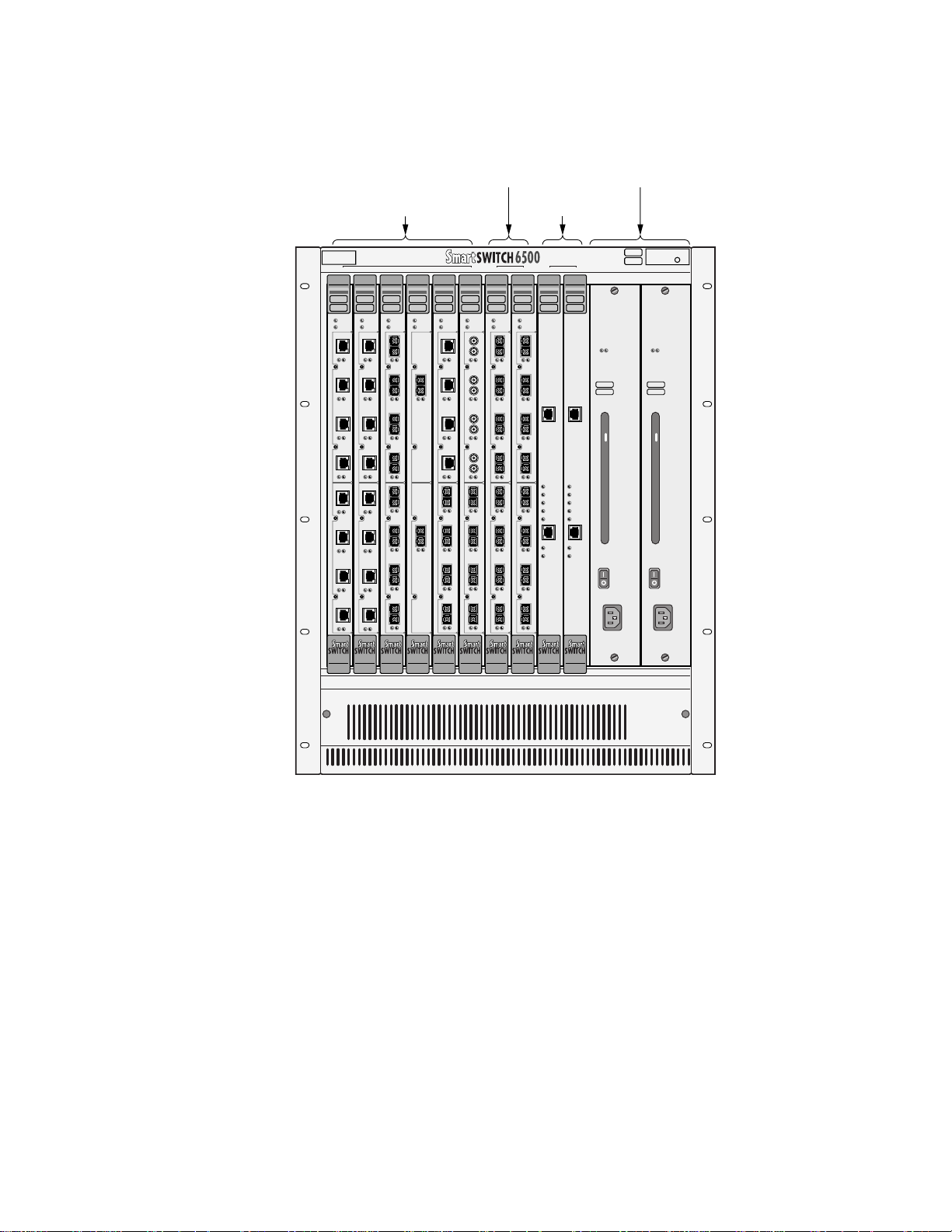
Figure 2-1 SmartSwitch 6500 chassis. . . . . . . . . . . . . . . . . . . . . . . . . . . . . . . . . . . . . . . . . . . . . . . . . . . . . . . . . . . 2-2
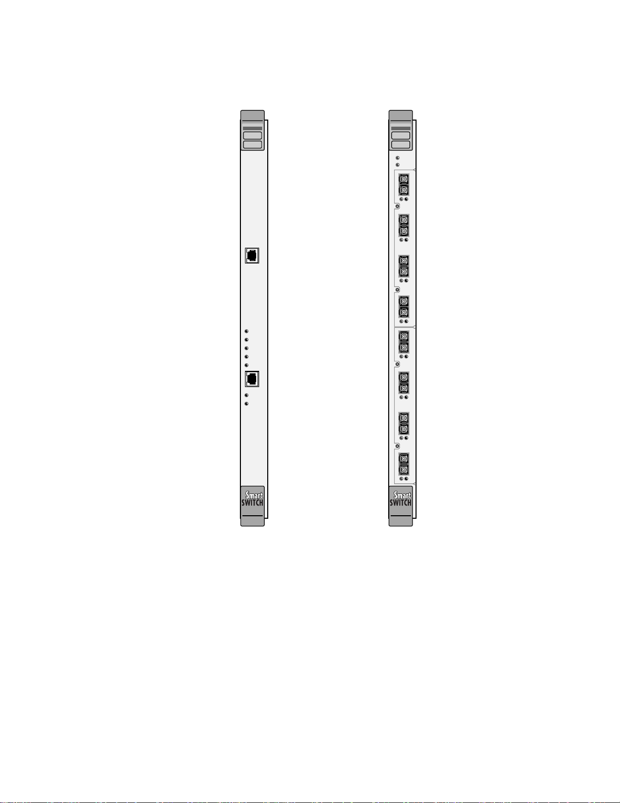
Figure 2-2 SmartSwitch CSM and TSM modules . . . . . . . . . . . . . . . . . . . . . . . . . . . . . . . . . . . . . . . . . . . . . . . . . 2-3
Figure 2-3 Rack mounting the SmartSwitch 6500 chassis . . . . . . . . . . . . . . . . . . . . . . . . . . . . . . . . . . . . . . . . . . . 2-5
Figure 2-4 Module placement in the SmartSwitch 6500 chassis . . . . . . . . . . . . . . . . . . . . . . . . . . . . . . . . . . . . . . 2-7
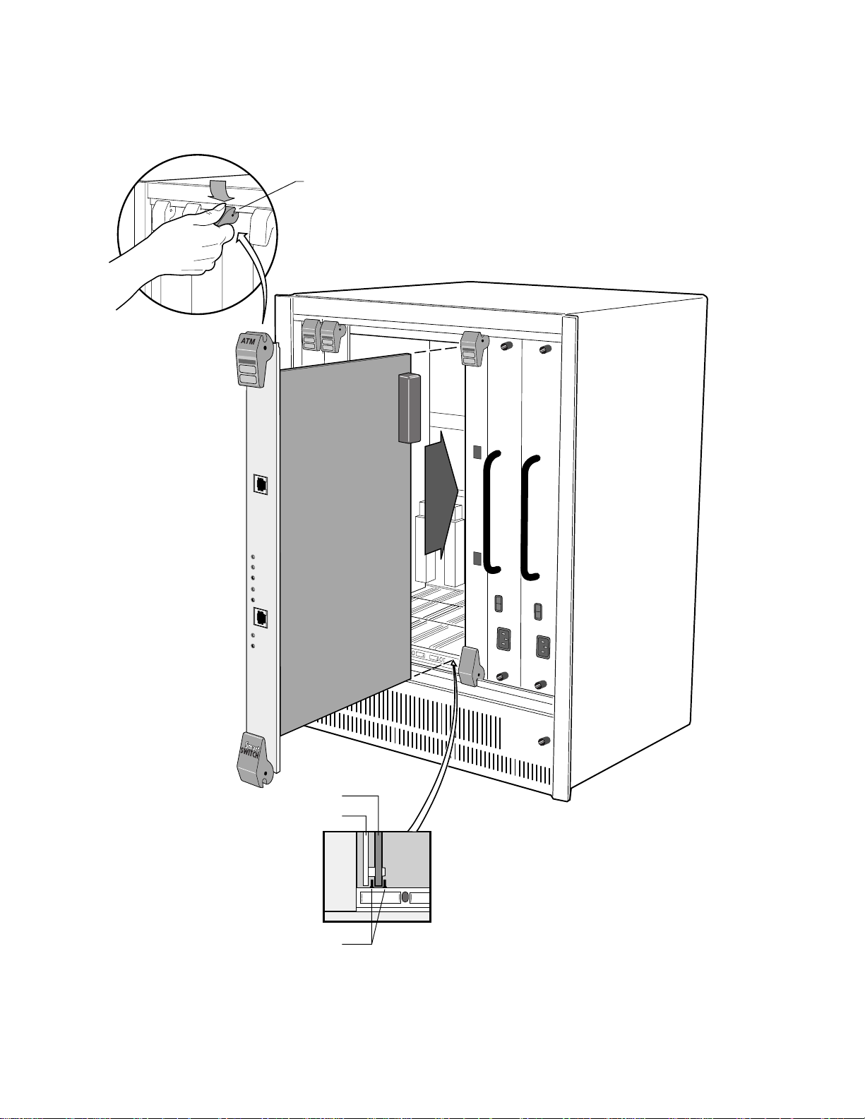
Figure 2-5 Installing CSM in slot 9 . . . . . . . . . . . . . . . . . . . . . . . . . . . . . . . . . . . . . . . . . . . . . . . . . . . . . . . . . . . . 2-8
Figure 2-6 Difference between TSM module and TSM/CPU module . . . . . . . . . . . . . . . . . . . . . . . . . . . . . . . . . . 2-9
Figure 2-7 Installing a TSM/CPU module in slot 8 . . . . . . . . . . . . . . . . . . . . . . . . . . . . . . . . . . . . . . . . . . . . . . . 2-10
Figure 2-8 SmartSwitch 6500 chassis with Ethernet switch, TSMs, and CSMs . . . . . . . . . . . . . . . . . . . . . . . . . 2-12
Figure 2-9 SmartSwitch 6500 connections for configuration. . . . . . . . . . . . . . . . . . . . . . . . . . . . . . . . . . . . . . . . 2-16
Figure 2-10 CSM and TSM LEDs . . . . . . . . . . . . . . . . . . . . . . . . . . . . . . . . . . . . . . . . . . . . . . . . . . . . . . . . . . . . . 2-20
Figure 2-11 SmartSwitch ATM Administrator. . . . . . . . . . . . . . . . . . . . . . . . . . . . . . . . . . . . . . . . . . . . . . . . . . . . 2-26
Figure 4-1 Physical connectivity for multi-peer group example . . . . . . . . . . . . . . . . . . . . . . . . . . . . . . . . . . . . . . 4-3
Figure 4-2 Logical representation of connectivity between groups A and B . . . . . . . . . . . . . . . . . . . . . . . . . . . . .4-6
Figure 4-3 Adding a third PNNI node for next level connectivity . . . . . . . . . . . . . . . . . . . . . . . . . . . . . . . . . . . . . 4-7
Figure 4-4 Aggregation token values and parallel links . . . . . . . . . . . . . . . . . . . . . . . . . . . . . . . . . . . . . . . . . . . . 4-10
Figure 5-1 IISP route across PNNI domain . . . . . . . . . . . . . . . . . . . . . . . . . . . . . . . . . . . . . . . . . . . . . . . . . . . . . . 5-3
Figure 5-2 Routes needed for a second IISP switch . . . . . . . . . . . . . . . . . . . . . . . . . . . . . . . . . . . . . . . . . . . . . . . . 5-3
Figure 5-3 IP routing through SW1 for connectivity to the Ethernet network. . . . . . . . . . . . . . . . . . . . . . . . . . . .5-7
Figure 6-1 Terminating PVPs . . . . . . . . . . . . . . . . . . . . . . . . . . . . . . . . . . . . . . . . . . . . . . . . . . . . . . . . . . . . . . . . . 6-7
Figure 8-1 Memory locations affected by the boot load commands. . . . . . . . . . . . . . . . . . . . . . . . . . . . . . . . . . . . 8-3
Figure B-1 Internet MIB hierarchy . . . . . . . . . . . . . . . . . . . . . . . . . . . . . . . . . . . . . . . . . . . . . . . . . . . . . . . . . . . . .B-2
Figure B-2 CSI ZeitNet Private MIBs. . . . . . . . . . . . . . . . . . . . . . . . . . . . . . . . . . . . . . . . . . . . . . . . . . . . . . . . . . .B-3
Figure B-3 Cabletron SmartSwitch 6500 object identifier example . . . . . . . . . . . . . . . . . . . . . . . . . . . . . . . . . . . . B-4
SmartSwitch 6500 User Guide xiii
Page 14

List of Figures
xiv SmartSwitch 6500 User Guide
Page 15

List of Tables
LIST OF TABLES
Table 2-1 I/O module ID numbers . . . . . . . . . . . . . . . . . . . . . . . . . . . . . . . . . . . . . . . . . . . . . . . . . . . . . . . . . . . . 2-4
Table 2-2 Module combinations in 6500 chassis . . . . . . . . . . . . . . . . . . . . . . . . . . . . . . . . . . . . . . . . . . . . . . . . 2-12
Table 2-3 CSM LEDs . . . . . . . . . . . . . . . . . . . . . . . . . . . . . . . . . . . . . . . . . . . . . . . . . . . . . . . . . . . . . . . . . . . . . 2-19
Table 2-4 TSM LEDs . . . . . . . . . . . . . . . . . . . . . . . . . . . . . . . . . . . . . . . . . . . . . . . . . . . . . . . . . . . . . . . . . . . . . 2-19
Table 2-5 Default accounts and passwords . . . . . . . . . . . . . . . . . . . . . . . . . . . . . . . . . . . . . . . . . . . . . . . . . . . . . 2-27
Table 3-1 ELAN Join Policies. . . . . . . . . . . . . . . . . . . . . . . . . . . . . . . . . . . . . . . . . . . . . . . . . . . . . . . . . . . . . . . 3-10
Table 7-1 Traffic descriptor type number explanation . . . . . . . . . . . . . . . . . . . . . . . . . . . . . . . . . . . . . . . . . . . . . 7-2
Table 8-1 Boot load commands . . . . . . . . . . . . . . . . . . . . . . . . . . . . . . . . . . . . . . . . . . . . . . . . . . . . . . . . . . . . . . 8-2
Table 9-1 Settings for Class of Service Queues . . . . . . . . . . . . . . . . . . . . . . . . . . . . . . . . . . . . . . . . . . . . . . . . . . 9-4
Table A-1 Hardware Specifications . . . . . . . . . . . . . . . . . . . . . . . . . . . . . . . . . . . . . . . . . . . . . . . . . . . . . . . . . . .A-1
Table A-2 Physical Specifications . . . . . . . . . . . . . . . . . . . . . . . . . . . . . . . . . . . . . . . . . . . . . . . . . . . . . . . . . . . . .A-1
Table A-3 ATM Port Specifications . . . . . . . . . . . . . . . . . . . . . . . . . . . . . . . . . . . . . . . . . . . . . . . . . . . . . . . . . . .A-2
Table A-4 Protocols Standards and Specifications . . . . . . . . . . . . . . . . . . . . . . . . . . . . . . . . . . . . . . . . . . . . . . . .A-2
Table A-5 Management Standards and Specifications. . . . . . . . . . . . . . . . . . . . . . . . . . . . . . . . . . . . . . . . . . . . . .A-3
Table A-6 RJ-45 to DB-9 Adapter (PC Serial Port Adapter) . . . . . . . . . . . . . . . . . . . . . . . . . . . . . . . . . . . . . . . . .A-3
Table B-1 Zeitnet proprietary MIB groupings . . . . . . . . . . . . . . . . . . . . . . . . . . . . . . . . . . . . . . . . . . . . . . . . . . .B-4
SmartSwitch 6500 User Guide xv
Page 16

List of Tables
xvi SmartSwitch 6500 User Guide
Page 17

1 INTRODUCING THE SMARTSWITCH 6500
Welcome to the SmartSwitch 6500 User Guide. The SmartSwitch 6500 is a high-performance ATM switch that
supports 10 Gbps non-blocking capacity, massive buffering capabilities, superior traffic management and shaping, a
wide variety of port interfaces, and redundancy for fault tolerance in backbone environments.
The SmartSwitch 6500 fits into the SmartSwitch 6C1 10 chassis, and is bas ed on a multi-module architect ure consisting
of the following three main modules
•
Cell Storage module (CSM), contains the cell memory (512k cells)
•
Translation and Scheduling module (TSM), supports the physical ports and hardware for traffic
management an d shaping
•
CPU module (daughter card on TSM), contains the hardware for running the SmartSwitch 6500
system software
•
Input/Output modules (IOM), provides the physical ATM ports (daughter cards on TSM)
Collectively, by communicating with each other over the chassis’ high-speed backplane, these modules make up the
SmartSwitch 6500, an integrat ed, high performance, ATM backbone switch. Furth ermore, SmartSwitch 6500 modu les
can coexist within the SmartSwitch 6C110 chassis with other Cabletron networking devices. For example, th e slots of
the 6C110 chass is can be populat ed by a mix of S martSwitch 6500 mo dules an d Smar tSwit ch 600 0 Eth ernet switches .
Both the CSM and TSM are hot swappable. This means that you can install and remove TSMs and CSMs from the
6C110 chassis without turning of chassis power. However, removing either the active CSM or TSM/CPU does not
trigger automatic switch-over to the redundant modules. For switch-over to occur the SmartSwitch 6500 must be
rebooted.
By performing the steps described in the next two chapters of this manual, your switch will be physically assembled
and installed, accessible on your Ethernet network, configured for redundancy, and running either an IP over ATM
VLAN or an emulated Ethernet or Token Ring LAN.
Subsequent chapters provi de instruction s and information abo ut switch use, main tenance, and proble m solving. These
topics include
•
Creating multi-level PNNI network topologies
•
Creating PVCs and PVP connections
•
Creating and using virtual ports
•
Adding routes
•
Dealing with bandwidth and controlling congestion
•
Upgrading software
•
Troubleshooting
Note For detailed descriptions of SmartSwitch 6500 console commands and their use,
see the SmartSwitch 6500 Reference Manual.
SmartSwitch 6500 User Guide 1-1
Page 18

SmartSwitch 6500 Modules Introducing the SmartSwitch 6500
1.1 SMARTSWITCH 6500 MODULES
Before continuing, read the following section. This section is provided to quickly give you a better, more detailed
understanding of the function and operation of each of the SmartSwitch 6500’s modules.
1.1.1 Cell Storage Module (CSM)
CSMs provide the main switching fabric for the SmartSwitch 6500. The CSM also provides cell storage and output
queuing, and dynamically shares memory among all active connections. The CSM monitors overall utilization of
shared memory and communicates this information to the TSM modules, where it’s used in making decisions about
incoming cell-acceptance. The CSM controls TSM access to the backplane cell data busses at both ingress
(TSM-to-CSM) and egre ss (CS M -to-TSM). The CSM can also provid e cl ock an d sy nc s i gnal gen erat i on f or net wo rk
clocking.
For redundancy, the SmartSwitch 6500 supports up to two CSMs in a single 6C110 chassis. When one CSM is active,
the other CSM is in standby mode. If the active CSM fails, the standby CSM can be made to assumes the active role.
Note CSMs must reside in SmartSwitch 6C110 chassis slots nine (9) or ten (10).
1.1.2 Translation and Scheduling Module (TSM)
TSMs are responsible for SmartSwitch 6500 traffic management functions. For example, TSMs perform header
translation for ingress and egress cell traffic, provide por t queue management for ABR (including EPD and PPD during
congestion), and EFCI marking for forward congestion. TSMs are responsible for per-port/per-class queue
management, cell scheduling and both physical and logical multicast support. TSMs also provide system interfaces for
the CPU modules, the SAR, and all I/O modules.
The SmartSwitch 6C110 chassis can contain up to eight TSMs, two of which can contain CPU modules. Also, each
TSM can support up to two IOMs; depending on the interface type, this pro vides each TSM with up to eight ATM ports.
1.1.3 CPU Module
CPU module are mounte d on TSMs as a daughter cards. Th e CPU module runs the sys tem software, an d provides both
intra-switch and inter-switch communication for configuration and monitoring. The CPU module is also responsible
for providing both a serial and Ethernet interface, through which the user interface and network management facilities
are accessed.
Note While the CPU module provides the serial and Ethernet interfaces, the external
connectors for these interfaces reside on the CSM module.
For redundancy, the SmartSwitch 6500 allows two CPU modules (each mounted on a separate TSM) to exist within
the same SmartSwitch 6C100 chassis. When one CPU module is active, the other CPU is in standby mode. If the active
CPU module fails, the standby CPU module can be made to assumes the active role.
1-2 SmartSwitch 6500 User Guide
Page 19

Introducing the SmartSwitch 6500 SmartSwitch 6500 Modules
Note The TSMs that support the CPU modules must reside in SmartSwitch 6C110
chassis slots seven (7) or eight (8).
1.1.4 Input/Output Modules (IOMs)
IOMs provide the physical ATM ports for the SmartSwitch 6500 and are mounted as daughter cards on the TSMs. The
TSMs of the SmartSwitch 6500 support a number of different I/O modules with a variety of interfaces and media types;
I/O modules are described in detail in Appendix A, "Specifications." Each TSM can support up to two I/O modules,
and each I/O module provides four physical ports (one physical port per OC-12 I/O module). This allows for a
maximum of eight ports per TSM, and a total of 64 ports for a SmartSwitch 6C110 chassis populated by the maximum
number of TSMs (eight TSMs).
SmartSwitch 6500 User Guide 1-3
Page 20

SmartSwitch 6500 Modules Introducing the SmartSwitch 6500
1-4 SmartSwitch 6500 User Guide
Page 21

2 SWITCH INSTALLATION AND SETUP
After reading this chapter, you will be able to perform the following tasks:
•
Install the SmartSwitch 6500 switch modules into th e Sm artS witch 6500 chassis
•
Complete the initial configuration
•
Use the console interface
•
Install the SmartSwitch ATM Admin istrator graphical management software
Note For detailed information about setting up the SmartSwitch Chassis (6C110), see
the 6C110 SmartSwitch 6500 Overview and Setup Guide.
2.1 RECEIVING THE SMARTSWITCH 6500
Your SmartSwitch 6500 is shipped to you in several cartons. The number of cartons and their contents depends on
which components you order.
2.1.1 Inspecting the Order
The following is a general list of cartons and their contents that comprise a SmartSwitch 6500.
•
SmartSwitch 6500 chassis with fan tray installed (see Figure 2-1)
•
6C205-3 power supply (or supplies); one per carton
•
CSM module (or modules); one unit per carton (see Figure 2-2)
•
TSM module (or mo dules) with CP U daugh ter b oard and I /O modul es i nstalled ; on e unit per carton
(see Figure 2-2 and Figure 2-6)
-
Additional TSMs (without CPU daughter boards) with I/O modules installed; one unit per
carton
SmartSwitch 6500 User Guide 2-1
Page 22

Receiving the SmartSwitch 6500 Switch Installation and Setup
10987654321
PS1 PS2CSMTSM/CPUTSM
Figure 2-1 SmartSwitch 6500 chassis
2-2 SmartSwitch 6500 User Guide
Page 23
Switch Installation and Setup Receiving the SmartSwitch 6500
CSM TSM
ATM
COM
POWER
ACTIVE
STANDBY
FAIL
ENET RDY
ENET
TX DATA
RX DATA
ATM
FAIL/OKTSM
FAIL/ MODECPU
123
NO SYNC
DATA
6A-IOM-21-4
4
123
NO SYNC
DATA
6A-IOM-21-4
B
4
Figure 2-2 SmartSwitch CSM and TSM modules
2.1.2 Unpacking
1. Carefully unpack each component of the SmartSwitch 6500 (chassis, TSMs, CSM, and so on).
Inspect each component for damage. Do not attempt to install damaged components. Contact the
Cabletron Systems Global Contact Center immediately (see Appendix C, "Technical Support")
2. Inspect the TSMs. Make certain that the I/O modules installed are of the correct type and number
(See Table 2-1).
SmartSwitch 6500 User Guide 2-3
Page 24

Receiving the SmartSwitch 6500 Switch Installation and Setup
Table 2-1 I/O module ID numbers
Face Plate Number Physical Specification
IOM-21-4
IOM-22-4
IOM-29-4
IOM-29-4-IR
IOM-29-4-LR
IOM-31-1
IOM-39-1
IOM-39-1-LR
IOM-67-4
IOM-77-4
155 Mbps OC-3/STM-1, MMF/SC (4 port)
155 Mbps STS-3c/STM-1, U TP-5/RJ-45 (4port)
155 Mbps OC-3/STM-1, SMF-IR/SC (1port) MMF/SC (3 port)
155 Mbps OC-3/STM-1, SMF-IR/SC (4 port)
155 Mbps OC-3/STS-1, SMF-LR/SC (4 port)
622 Mbps OC-12/STM-4, MMF/SC (1 port)
622 Mbps OC-12/STM-4, SMF-IR/SC (1 port)
622 Mbps OC-12/STM-4, SMF-LR/SC (1 port)
45 Mbps DS-3, Coax/BNC (4 port)
34 Mbps E-3, Coax/BNC (4 port)
If the I/O module configuration is incorrect, contact the Cabletron Systems Global Contact Center immediately.
2.1.3 Check Accessory Carton Contents
Open the accessory carton and check that it contains the following items:
— 7-foot UTP cable terminated on both ends with RJ-45 connectors
— RJ-45 to 9-pin female adapter (labeled PC)
— Console cabling instruction sheet
— Diskettes containing switch software, MIB files, and release notes
— SmartSwitch 6500 Release Notes
— CD-ROM containing SmartSwitch ATM Administrator software for Windows 95/98, Windows NT, and Solaris
2.4/2.5
— CD-ROM containing the SmartSwitch 6500 User Guide, Reference Manual, related manuals, and Acrobat Reader
If any of these items is missing, contact the Cabletron Systems Global Contact Center immediately.
2-4 SmartSwitch 6500 User Guide
Page 25

Switch Installation and Setup Switch Installation and Assembly
2.2 SWITCH INSTALLATION AND ASSEMBLY
The following is a list of steps for assembling your Sm artS witch 6500. Refer to Figure 2-4 for proper module
placement.
2.2.1 Mounting the Chassis
1. Find someone to assist you. The SmartSwitch 6500 chassis is heavy enough to make this a
two-person task.
2. Select a spot on a standard 19 inch equipment rack that provides at least two inches of air space
above and below the chassis. This is necessary for proper ventilation and heat dissipation.
3. Secure the SmartSwitch 6500 to the equipment rack using the screws provided with the equipment
rack. The chassis is secured by ten screws, five screws per side (see Figure 2-3).
Rack Mount
Figure 2-3 Rack mounting the SmartSwitch 6500 chassis
2.2.2 Installin g The Power Supplies
Chassis
PS1 PS2CSMTSM/CPUTSM
10987654321
Install
Mounting
Hardware
(10 Places)
1. Using a flat blade screwdriver, unscrew and remove the metal power supply blanks. The power
supply blanks r eside in the slots labeled PS1 and PS 2.
SmartSwitch 6500 User Guide 2-5
Page 26

Switch Installation and Assembly Switch Installation and Setup
Warning Never attempt to install a power supply whi le it is plugged in and operating.
2. With the power supply’ s power cord receptacle at the bottom, align the top and bo ttom of the power
supply with the tracks in the slot. Slide the p ower supply into the chassis. If properly aligned, the
power supply should slip in easily. Do not force the power supply; if it binds during insertion,
remove the power supply and try inserting it again.
Note The power supply obscures the view of the tracks at the bottom of the chassis, so
be sure to look at that area as you begin to slide the power supply into the chassis.
3. With the power supply in contact with the chassis backplane, press firmly until the power supply
engages with the backplane’s power connector.
4. Use a flat blade screwdriver to secure the power supply to the SmartSwitch chassis by tightening the
two attached, slotted screws.
5. Insert the power cord into its receptacle on the front of the power supply. Plug the other end of the
power cord into an appropriate power outlet.
If your SmartSwitch 6500 has a second power supply, repeat steps 1 through 5.
2-6 SmartSwitch 6500 User Guide
Page 27
Switch Installation and Setup Switch Installation and Assembly
TSM
TSM
(Without CPU) or
Other Modules
Slots 1–6
With CPU
Slots 7 & 8
CSM
Slots 9 & 10
Power
Supplies
2
1
ATM
ATM
ATM
TSM
TSM
TSM
FAIL/OK
FAIL/OK
CPU
FAIL/MODE
CPU
FAIL/MODE
CPU
1234
1234
123
NO SYNC
DATA
NO SYNC
DATA
6A-IOM-29-4-IR
6A-IOM-22-4
6A-IOM-22-4
4
123
1234
1234
NO SYNC
NO SYNC
6A-IOM-21-4
6A-IOM-22-4
6A-IOM-22-4
B
4
FAIL/OK
FAIL/MODE
NO SYNC
DATA
NO SYNC
DATA
ATM
ATM
TSM
TSM
FAIL/OK
FAIL/OK
FAIL/MODE
CPU
FAIL/MODE
CPU
NO SYNC
DATA
2
6A-IOM-31-1
6A-IOM-22-4
NO SYNC
DATA
123
NO SYNC
DATA
1
6A-IOM-21-4
6A-IOM-31-1
NO SYNC
DATA
B
B
4
109876543
COM
POWER
ACTIVE
STANDBY
FAIL
ENET RDY
ENET
TX DATA
RX DATA
ATM
COM
POWER
ACTIVE
STANDBY
FAIL
ENET RDY
ENET
TX DATA
RX DATA
PS1 PS2CSMTSM/CPUTSM
ATM
ATM
TSM
CPU
1234
123
6A-IOM-67-4
A
4
123
6A-IOM-29-4-IR
B
4
ATM
ATM
TSM
FAIL/OKTSM
FAIL/OK
FAIL/OK
FAIL/MODE
CPU
FAIL/MODE
NO SYNC
DATA
NO SYNC
DATA
FAIL/MODECPU
123
123
NO SYNC
DATA
NO SYNC
DATA
6A-IOM-21-4
6A-IOM-21-4
4
4
123
123
NO SYNC
DATA
NO SYNC
DATA
6A-IOM-29-4-IR
6A-IOM-21-4
B
B
4
4
REDUNDANCYPWR
100 - 125V - 8.0A
200 - 250V - 4.0A
50/60 Hz
REDUNDANCYPWR
100 - 125V - 8.0A
200 - 250V - 4.0A
50/60 Hz
Figure 2-4 Module placement in the SmartSwitch 6500 chassis
2.2.3 Installin g the CSM
Follow these instructions to install the CSM module into the chassis.
1. Remove the metal blank that covers either slot 9 or slot 10 of the chassis (CSMs can reside only in
slots 9 and 10). See the legend on the top edge of the SmartSwitch 6500 chassis.
2. Open the ejectors at the top and bottom of the CSM module.
3. With the ejector labeled
6A-CSM512
the tracks in the slot (see Figure 2-5).
4. Slide the CSM module into the chassis. The CSM module obscures the view of the tracks at the
bottom of the chassis, so be sure to look at that area as you begin to slide the module into the chassis.
5. Close the ejectors. The installation is complete.
at the top, align the top and bottom of the CSM module with
SmartSwitch 6500 User Guide 2-7
Page 28
Switch Installation and Assembly Switch Installation and Setup
If you have a second CSM module, repeat steps 1 through 5.
Rotate ejector
to lock in place
COM
POWER
ACTIVE
STANDBY
FAIL
ENET RDY
ENET
TX DATA
RX DATA
Circuit Card
Metal Backpanel
Figure 2-5 Installing CSM in slot 9
2-8 SmartSwitch 6500 User Guide
Card Guides
Page 29

Switch Installation and Setup Switch Installation and Assembly
2.2.4 Installing the TSM wi th CPU Daughter Board
Follow these instructions to install the TSM/C PU m odule into the chassis.
1. Make sure that the TSM has a CPU daughter board installed (see Figure 2-6).
2. Remove the metal blank that covers either slot 7 or slot 8 of the chassis (TSMs with CPU daughter
cards can reside only in slots 7 and 8). See the legend on the top edge of the SmartSwitch 6500
chassis.
3. Open the ejectors at the top and bottom of the TSM/CPU module.
4. With the ejector labeled
6A-TSM512
with the tracks in the slot (see Figure 2-7).
5. Slide the TSM/CPU module into the chassis. The TSM module obscures th e view of the tracks at the
bottom of the chassis, so be sure to look at that area as you begin to slide the module into the chassis.
6. Close the ejectors. The installation is complete.
If you have a second TSM/CPU modules, repeat steps 1 through 6.
at the top, align the top and bottom of the TSM/CPU module
CPU Daughter Board
TSM /CPU Combination
TSM without CPU Daughter Board
Figure 2-6 Difference between TSM module and TSM/CPU module
SmartSwitch 6500 User Guide 2-9
Page 30

Switch Installation and Assembly Switch Installation and Setup
Rotate ejector
to lock in place
10987654321
PS1 PS2CSMTSM/CPUTSM
Circuit Card
Metal Backpanel
Card Guides
Figure 2-7 Installing a TSM/CPU module in slot 8
2-10 SmartSwitch 6500 User Guide
Page 31

Switch Installation and Setup Switch Installation and Assembly
2.2.5 Installing Additional TSM Modules
TSM modules without CPU daughter boards can be installed in slots 1 through 6. See the legend on the top edge of
the SmartSwitch 6500 chassis. Follow thes e instructions to install additional TSM m odules.
Caution Do not attempt to insert a TSM module in either slot 9 or slot 10.
1. Remove the metal blank that covers one of the chassis’ slots.
2. Open the ejectors at the top and bottom of the TSM module.
3. With the ejector labeled
6A-TSM512
the tracks in the slot.
4. Slide the TSM module into the chassis. The TSM module obscures the view of the tracks at the
bottom of the chassis, so be sure to look at that area as you begin to slide the module into the chassis.
5. Close the ejectors. The installation is complete.
If you have additional TSM modules, repeat steps 1 through 5.
at the top, align the top and bottom of the TSM mod ule with
2.2.6 Installing Other Modules in the SmartSwitch 6500 Chassis
If all SmartSwitch 6500 chassis slots are not occupied by TSMs, other Cabletron SmartSwitch double-wide devices
can reside within the chassis. For example, if slots are available, the ch assis can also co ntain Eth ernet switches, other
ATM switches, and so on (see Figure 2-8 for an example).
Table 2-2 shows the maximum number of TSMs and Cabletron SmartSwitch double-wide modules that can be
installed in the same SmartSwitch 6500 chassis.
SmartSwitch 6500 User Guide 2-11
Page 32

Switch Installation and Assembly Switch Installation and Setup
1
ETHERNET
RESET
CPU
1X
3X
5X
7X
9X
11X
13X
15X
17X
19X
21X
23X
2
ATM
ATM
TSM
TSM
FAIL/OK
CPU
FAIL/MODE
CPU
COM
123
NO SYNC
DATA
1
2
34
56
78
910
11 12
13 14
15 16
17 18
19 20
21 22
23 24
2
6A-IOM-29-4-IR
6A-IOM-31-1
4
123
NO SYNC
DATA
1
6A-IOM-31-1
6A-IOM-21-4
APIM 1 APIM 2
B
B
4
ATM
TSM
TSM
FAIL/OK
FAIL/OK
FAIL/OK
FAIL/MODE
NO SYNC
DATA
NO SYNC
DATA
FAIL/MODE
CPU
FAIL/MODE
CPU
1234
123
NO SYNC
DATA
NO SYNC
DATA
6A-IOM-22-4
6A-IOM-67-4
A
4
123
123
NO SYNC
DATA
NO SYNC
DATA
6A-IOM-29-4-IR
6A-IOM-21-4
B
B
4
4
ATM
TSM
FAIL/OKTSM
FAIL/OK
FAIL/MODE
CPU
FAIL/MODECPU
123
123
NO SYNC
DATA
DATA
6A-IOM-21-4
6A-IOM-21-4
4
4
123
123
NO SYNC
DATA
DATA
6A-IOM-29-4-IR
6A-IOM-21-4
B
B
4
4
ATM
ATM
109876543
PS1 PS2CSMTSM/CPUTSM
ATM
ATM
REDUNDANCYPWR
100 - 125V - 8.0A
200 - 250V - 4.0A
50/60 Hz
COM
POWER
ACTIVE
STANDBY
FAIL
ENET RDY
ENET
TX DATA
RX DATA
REDUNDANCYPWR
100 - 125V - 8.0A
200 - 250V - 4.0A
50/60 Hz
NO SYNC
COM
POWER
ACTIVE
STANDBY
FAIL
NO SYNC
ENET RDY
ENET
TX DATA
RX DATA
Figure 2-8 SmartSwitch 6500 chassis with Ethernet switch, TSMs, and CSMs
Table 2-2 Module combinations in 6500 chassis
Number of double-wide 6000 modules Installed 0 1 2 3
Number of TSM modules that can be installed 8 6 4 2
2-12 SmartSwitch 6500 User Guide
Page 33

Switch Installation and Setup Configuring the Switch
2.3 CONFIGURING THE SWITCH
This section describes the steps necessary to configure your SmartSwitch 6500 for operation. Configuration is divided
into two operations: initial network configuration and backup/redundancy configuration. Initial network configuration
makes the SmartSwitch 6500 accessible by the rest of your network. Backup/redundancy con figuration allows you to
save switch configurations and specify the files from which the slave TSM/CPU gets its configuration in the event the
master TSM/CPU fails.
2.3.1 Initial Network Configuration
Initial network configuration of your SmartSwitch 6500 consists of making a terminal connection with the switch
through the COM port to set the switch name, IP address, and subnet mask for the switch’ s Ethern et port. Onc e these
tasks are complete, the switch can be reached over your Ethernet network for additional configuration and
administration.
Perform the following steps to configure initial s w itch parameters.
Note If you have a redundant CSM, make the physical conn ectio ns descr ibed below to
the CSM in slot 9. By default, the CSM in slot 9 is the master CSM and is the only
module with active
COM
and
ENET
ports.
1. Configure a dumb terminal or workstat i on runn in g t ermi nal emul at ion soft ware wit h th e fol lowi ng
communication parameters:
•
Terminal emulation = VT100
•
Baud rate = 9600
•
Data bits = 8
•
Stop bits = 1
•
Flow control = none
2. Plug one end of the supplied RJ-45 UTP cable into the 9-pin RJ-45 adapter (see Fig ure 2-9).
3. Plug the other end of the UTP cable into the Master CSM’s female RJ-45 jack labeled
Figure 2-9).
4. Connect the master CSM module to your network by plugging a UTP cable into the CSM’s female
RJ-45 jack labeled
5. Start the dumb terminal or workstation term inal emulation software.
6. As soon as power is applied to the SmartSwitch 6500, the module emits a series of diagnostic
messages.
7. After the diagnostics are finished, the switch prompts for a password. Enter the default password,
“admin.”
8. Next, the switch prompts for the information necessary to make it accessible through your Ethernet
network
•
Switch name
•
IP address
•
Subnet mask
(see Figure 2-9).
ENET
COM
(see
SmartSwitch 6500 User Guide 2-13
Page 34

Configuring the Switch Switch Installation and Setup
•
Default router — IP address of router (if any) that exists between the switch an d its TFTP server.
2-14 SmartSwitch 6500 User Guide
Page 35

Switch Installation and Setup Configuring the Switch
The following is an example of the init ial network configuration session .
Note For the sake of brevity, the start up messages have been abridged.
SmartSwitch 6500 Start-up Code
Cabletron Systems Inc.
Press any key to exit to Boot Load Prompt:
01
Bypassing POST
Verifying Checksum of Switch Software...
SmartSwitch Command Console
SmartSwitch Version 02.02.0 (c) Cabletron Systems Inc.
password: : admin
The current user is Administrator
Could not find setup file
Running Setup Automatically
SwitchName(Smart6500) : my_switch
IPAddress(10.0.0.1) : 206.61.237.22
IPNetMask(255.255.255.0) : 255.255.255.0
Default Router() : 206.61.237.5
Confirm(y/n)?:y
Changing IP Address on System. Telnet session (if any) will be lost.
my_switch #
< “admin” is the default password
< a switch name
< an IP address
< a subnet mask
< router through which the switch accesses its bac kup T FTP server
Note At this point, it’s advisable to use the passwd command to change the default
password.
9. Log off the local console connection. You can now perform additional configur ation steps over your
network using a telnet connection.
Note Only one console connection is allowed at any time. To reach the SmartSwitch
6500 through telnet, you must exit the local terminal connectio n by entering the
exit command.
SmartSwitch 6500 User Guide 2-15
Page 36

Configuring the Switch Switch Installation and Setup
Terminal
RJ-45 Port
10987654321
ATM
FAIL/OKTSM
FAIL/MODECPU
123
NO SYNC
DATA
6A-IOM-21-4
ATM
PS1 PS2CSMTSM/CPUTSM
REDUNDANCYPWR
REDUNDANCYPWR
COM
4
POWER
123
NO SYNC
DATA
6A-IOM-21-4
B
4
ACTIVE
STANDBY
FAIL
ENET RDY
ENET
TX DATA
RX DATA
100 - 125V - 8.0A
200 - 250V - 4.0A
50/60 Hz
100 - 125V - 8.0A
200 - 250V - 4.0A
50/60 Hz
Figure 2-9 SmartSwitch 6500 connections for configuration
Terminal
Ethernet
RJ-45 Port
Network
2.3.2 Backup/Redundancy Configuration
Backup/redundancy confi guration con sists of sett ing up the S martSwitch 6 500 to save con figuration backup files u sed
by the master TSM/CPU and slave TSM/CPU (if any). The backup configuration file contains all configuration
changes made to the master TSM/CPU. For example, the backup file con tains E LAN infor mation, port configuration
changes, PVCs, and so on.
Note The backup file does not contain an image of the switch operating firmware. For
information on upgrading or replacing switch firmware, see Chapter 8, "Upgrades
and Firmware."
2-16 SmartSwitch 6500 User Guide
Page 37

Switch Installation and Setup Configuring the Switch
Perform the following steps to configure backup capabilities.
1. On a workstation that can be reached by your SmartSwitch 6500 and is running TFTP server
software, create a file under the /tftpboot directo ry. This file is used as the backup file by the master
TSM/CPU and can initially be blank.
2. Make sure that the SmartSwitch 6500 has full read/write priv ileges to the file.
3. Enter the backup switch command on the SmartSwitch 6500. Specify the IP address of the TFTP
server and the full path and file name to the backup file. For example:
Smart6500 # backup switch
ServerIP() : 206.61.237.40
Path(public/Smart6500.ztr) : /tftpboot/backup.ztr
Smart6500 #
IP address of the backup TFTP server
<
< full path and file na me
Note Depending upon whether your TFTP server is running in secure or non-secure
mode, you may not need to specify
/tftpboot in the path to the backup file. If you
experience access violation errors, try leaving off /tftpboot from the path.
Note It’s a go od idea to backup the Smar tSwitch 6500 each time you make a permanent
or significant change to the switch’s configuration.
Once the SmartSwitch 6500 configuration is backed up, you can restore the master TSM/CPU configuration by
entering the
Smart6500 # restore switch
ServerIP(206.61.237.40) :
Path(tftpboot/backup/smart6500.ztr) :
Backup file is valid.
Restoring a backup file will completely replace any data stored in the flash, and requires a switch
reboot
Are you sure this is what you want to do?
Confirm(y/n)?:y
Restoration complete.
Rebooting is required to ensure correct operation,
Do you want to reboot now?
Confirm(y/n)?:y
restore switch command. For example:
< Remembers last IP address entered
< Remembers last path and file name entered
< Yes, restore the configuration
< Yes, reboot the switch
Redundancy Configuration for the Slave TSM/CPU
In the event the master TSM/CPU fails, the slave TSM/CPU module assumes the role of master. To do this, the slave
TSM/CPU must know the location of a configuration file from which to obtain switch configuration informat ion.
When rebooted, the new master TSM/CPU automatically configures itself using the information contained within the
configuration file. Use the
set redundancyinfo command to tell the slave TSM/CPU the location and name of its
configuration file.
SmartSwitch 6500 User Guide 2-17
Page 38

Configuring the Switch Switch Installation and Setup
The following example tells the slave TSM/CPU to use the master TSM/CPU’s backup file as its configuration file.
The master TSM/CPU’s backup file is
Smart6500 # set redundancyinfo
HostIP() : 206.61.237.40
PathFileName() : /tftpboot/backup.ztr
Updating Slave redundancy config. Please wait...
Smart6500 #
backup.ztr, and it’s located in the /tftpboot directory:
< IP address of the TFTP server
< full path and file name of master’s backup file
Using the master TSM/CPU’s backup file as the slave’ s configuration file assures that if the slave assumes the role of
master, it will be configured identical to the previous master (ELANs, PVCs, PVPs, port settings, and so on). Y ou can,
however, instruct the slave TSM/CPU to use a file other than the master’s backup file as its configuration file.
Note Remember that the slave TSM/CPU’s configuration file must already exist and
reside within the /tftpboot directory of the TFTP server.
Keep in mind that the
use a configuration file other than the master TSM/CPU’s backup file, the
backup switch command updates only the master’s backup file. If the slave TSM/CPU is set to
Backup Switch command does not update
the slave’s configuration file with the master’s current configuration.
If the slave’ s configu ration fi le is not the master’s backup file, use the
execute redundancyconfigbackup command
to sync the slave’s configuration file with the master’s current configuration. For example:
luxor2 # execute redundancyconfigbackup
Backup successful
luxor2 #
The slave TSM/CPU’s configuration file now contains the current configuration of the master TSM/CPU.
Redundancy Configuration for CSMs
The SmartSwitch 6500 can use two CSM modules: one active (master), the other in standby (slave). By default, the
CSM in slot 9 is recognized as the active (master) CSM by the active TSM/CPU module. To set the slave CSM as the
master CSM perform the following steps:
1. Access the bootline prompt by rebooting the SmartSwitch 6500, then pressing a key during the start
up countdown .
2. At the bootline prompt, enter the scsm command. Mastership is transferred to the redundant CSM.
Notice that the console becomes inactive.
3. Transfer both the COM port and Ethernet port cables to the new master CSM module, then press the
space-bar to regain control of the console.
4. At the bootline prompt, ent er the go command to allow the SmartSwitch 6500 to proceed with start
up.
Note If the master CSM fails, move the COM port and Ethernet port cables to the slave
CSM. Remove the failed CSM from the chassis and press the reset button. At start
up, the master TSM/CPU will automatically discover the slave CSM and use it as
the new master CSM.
2-18 SmartSwitch 6500 User Guide
Page 39

Switch Installation and Setup LED Descriptions
2.4 LED DESCRIPTIONS
Both the CSM and TSM modules display several LED indicator lights. T able 2-3 and Table 2-4 explain the color, state,
and meaning of the CSM and TSM indicator lights. Also, see Figure 2-10.
Table 2-3 CSM LEDs
LED Green Amber Red Unlit
POWER Power on No power
ACTIVE CSM is active CSM not active
*
STANDBY CSM is in standby
mode
CSM is not in standby
mode
FAIL CSM is in fail Normally o ff
ENET RDY Ethernet interface is
up and active
Ethernet interface not
*
active
TX DATA Normally flashing,
transmitting data on
Ethernet port
RX DATA Normally flashing,
receiving data on
Ethernet port
*
Slave CSM
Table 2-4 TSM LEDs
LED Green Amber Red Unlit
TSM FAIL/OK TSM is initialized TSM not initialized
*
CPU FAIL/OK CPU in active mode CPU in stan dby mode
CPU in fail No CPU on TSM
DATA Normally flashing when
connected, data is
passing through the port
NO SYNC Framer is not receiving
sync
*
Slave TSM/CPU
No data is passing
through port.
Normally off when
connected, Framer
is receiving sync
SmartSwitch 6500 User Guide 2-19
Page 40

Using the Console Switch Installation and Setup
Ejector
Reset Button
POWER
ACTIVE
STANDBY
FAIL
ENET RDY
(Ethernet interface ready)
TX DATA
RX DATA
CSM
ATM
COM
POWER
ACTIVE
STANDBY
FAIL
ENET RDY
ENET
TX DATA
RX DATA
TSM FAIL / OK
CPU FAIL / MODE
Console T erminal
(RJ-45)
Ethernet Port
(10Base-T)
Ejector
TSM
ATM
NO SYNC
FAIL/OKTSM
FAIL/MODECPU
123
NO SYNC
DATA
6A-IOM-21-4
I/O Module
4
123
NO SYNC
DATA
6A-IOM-21-4
B
I/O Module
DATA
DATA
NO SYNC
4
Ejector
Ejector
Figure 2-10 CSM and TSM LEDs
2.5 USING THE CONSOLE
Use the SmartSwitch 6500 console interface to configure and manage your switch. The following is a description of
the console interface and its operation.
2.5.1 Port Numbering
The following convention is used for numbering physical ports on the SmartSwitch 6500:
slot number I/O module letter port number
For example, port 3 of I/O module A on the TSM in slot 5 is represented by: 5A3
Vi rtual po rts are des i gnate d by a period (.), and the vi rtual po rt numb er is appen ded to t he phy sical por t number. For
example, virtual port 2 on physical port
7B1 is represented as: 7B1.2
2-20 SmartSwitch 6500 User Guide
Page 41

Switch Installation and Setup Using the Console
2.5.2 Console Commands
Note For detailed descriptions of all console commands, see the SmartSwitch 6500
Reference Manual.
All console commands use the syntax:
operator switch-attribute [<parameter 1> <parameter 2>... <parameter n>]
Where the operator is one of the following:
activate: Make a connection active.
add (create): Add a new instance of a switch-attribute.
backup: Backup the active TSM/CPU configuration.
clear: Clear a table, list, or configuration.
deactivate: Make a connection inactive.
delete (remove): Delete an instance of a switch-attribute.
execute: Perform the following action.
exit: Exit the switch console.
flush: Remove assigned values; for example, flush a route table.
modify (set): Change the values that currently define a switch-attribute.
show (display): Show the current values used by a switch-attribute.
start: Start a process on the switch; for example, start the LAN Emulation Configuration Server.
restart: Restart a process on the switch; for example, restart client.
restore: Restore the TSM/CPU configuration from its backup file.
SmartSwitch 6500 User Guide 2-21
Page 42

Using the Console Switch Installation and Setup
If a command requires parameter values, it prompts you for them. For instance, in the example below, show is the
operator,
information about port
Smart6500 # show portconfig 7a1
==================================================
Port: 7A1
------------------------------------------------- Parameter Configured Current
------------------------------------------------- Sig Type autoConfig pnni10
Sig Role other symmetric
Interface Type private private
Max vpi bits 0 0
Max vci bits 12 12
Max SVC vpci 0 0
Min SVC vci 32 32
Max Vccs 4096 4096
------------------------------------------------- Other parameters
------------------------------------------------- Port Admin Status UP
Ilmi Admin Status Enabled AddressRegistration Connectivity
Oper State UP
Trans Type STS-3c
Media Type MMF (S)
Bandwidth 155 MB
Smart6500 #
portconfig is the switch-attribute, and 7a1 is the parameter indicating that you want to show configuration
7A1.
If you don’t specify parameters with the command, the console prom pts you for an inp ut value and provides a defau lt
value display ed in p arenthe sis. For example, if yo u enter
show portconfig without specifying a port (as a parameter),
the following appears.
Smart6500 # show portconfig
PortNumber(ALL) :
Port Intf Sig ILMI Trans Media Max Used Oper
Name Type Type State Type Type Bw(MBS) Bw(MBS) State
==============================================================================
CPU private uni40 down STS-3c MMF (S) 155.0 13.87 up
CPU.1 private pnni10 down STS-3c MMF (S) 10.50 0.0 up
7A1 private autoConfig down STS-3c MMF (S) 155.0 0.0 down
7A2 private pnni10 up STS-3c MMF (S) 155.0 1.12 up
7A3 private autoConfig down STS-3c MMF (S) 155.0 0.0 down
7A4 private autoConfig down STS-3c MMF (S) 155.0 0.0 down
7B1 private uni30 up STS-3c MMF (S) 155.0 0.75 up
7B2 private pnni10 up STS-3c MMF (S) 155.0 0.75 up
7B3 private autoConfig down STS-3c MMF (S) 155.0 0.0 down
Smart6500 #
In the example above, the default of “all” ports is presented. You can either accept the default by pressing Enter, or
you can enter a specific port number.
Note When you accept the (all) default for show, the information displayed is often
abridged.
2-22 SmartSwitch 6500 User Guide
Page 43

Switch Installation and Setup Using the Console
2.5.3 Console Time-out
The console can be config ured t o ex it if it does not sense a key stroke within a defined l engt h of ti me. By default, the
SmartSwitch 6500 is set to never time out (value = 0). To activate the time-out feature, use the
set ConsoleTimeOut
command to adjust the time-out period:
Smart6500 # set consoletimeout
Timeout(0) : 30 <Will time-out in 30 minutes without input
Confirm (y/N)? : y
Smart6500 #
2.5.4 Creating an Alias
Use the add alias command to create shorter or easier-to-remember names for command lines. For example:
Smart6500 # add alias
AliasName() : traffic
AliasedString() : set switchtrafficcongestion
Smart6500 #
The above example creates an alias (traffic) that can be entered in place of the command set
SwitchTrafficCongestion
Smart6500 # traffic
LowEPDWatermark(4096) :
HighEPDWatermark(4096) :
CLP1_DiscardWatermark(4096) :
RMCellMarkingEnable(enable) :
ExplicitRateMarkingEnable(enable) :
EFCIMarkingEnable(enable) :
. For example:
Smart6500 #
Enter the show alias command to display a list of all defined aliases and the co mmand lines to which they correspond.
:Smart6500 # show alias
AliasName(ALL) :
Alias List
==============================================================================
Index Alias Name : Aliased Command
1 PING : Start ping
2 port : show portconfig
3 traffic : set switchtrafficcongestion
Smart6500 #
2.5.5 Ambiguous Commands
If you enter part of a command, and that part is not unique, the console displays a numbered list of possible matching
commands. For example, entering
“pnnin.” In response, the SmartSwitch 6500 displays a list of the possible commands:
Smart6500 # show pnnin
Objects beginning with pnnin for action show
0 : PnniNeighbor
1 : PnniNetworkLink
2 : PnniNetworkNode
3 : PnniNode
4 : PnniNodeTimer
(#)Command (Q)uit? : 3
Smart6500 # show PnniNode
show pnnin is ambiguous because there are several commands that start with
< “pnnin” is ambiguous
<
I meant PnniNode, so I enter number three (3) from the list
SmartSwitch 6500 User Guide 2-23
Page 44

Using the Console Switch Installation and Setup
Selecting number three from the list automatically enters the corresponding command; pressing enter executes the
command:
PNNI Node Information
================================================================================
Level : 80
Node Id : 50:a0:39:00:00:00:00:00:00:00:00:00:28:c1:80:00:20:d4:28:c1:80:00
Lowest : TRUE
Admin Status : UP
Oper Status : UP
Atm Address : 39:00:00:00:00:00:00:00:00:00:28:c1:80:00:20:d4:28:c1:80:00
Peer Group Id: 50:39:00:00:00:00:00:00:00:00:00:00:00:00
Rst Transit : FALSE
Rst Branching: FALSE
DB Overload : FALSE
Ptse : 2
Smart6500 #
2.5.6 Console Help
The console provides several levels of help for console commands. For example, to list the switch attributes that can
be used with a particular operator, enter the word
Smart6500 # help add
HELP ---- add
==============================================================================
add [ AlarmConfig | Alias | ATMRoute | BUSELAN | Community | ELAN |
Interface | IPATMClient | IPATMPVC | LANEClient | LECSELAN |
LECSELANLEC | LECSTLVSET | LESELAN | NetPrefix | PnniMetrics |
PnniSummaryAddress | PVC | Route | ServiceRegistry |
TrafficDescriptor | TrapCommunity ]
Smart6500 #
help (or ?) followed by the operator.
To obtain an explanation of a command and its parameters, enter the word help (or ?) before the command.
Smart6500 # ? add laneclient
Create LANE Client
============================================================================
ClientNumber Local Client Number (0-127)
LanName Name of the ELAN to join
ServerType Type of LANE Server [LECS, LES]
ServerAddress ATM Address of the LANE Server
IPAddress IP Address of the Client
NetMask IP Netmask of the Client
MTU MTU for the Client [1516, 9234, NONE]
Smart6500 #
While entering a command, you can obtain help about the current parameter by entering a question mark (?) at the
prompt. For example:
Smart6500 # add atmroute
PortNumber(A1) : a3
AtmAddress() : 39:00:00:00:00:00:00:00:00:00:14:72:80
PrefixLength(104) :
Index(0) :
Type(Internal) : ?
The type of reachability. Use Internal, Exterior, or Reject.
Type(Internal) :exterior
Scope(0) :
MetricsTag(0) :
Smart6500 #
< What does type mean?
2-24 SmartSwitch 6500 User Guide
Page 45

Switch Installation and Setup SmartSwitch ATM Administrator
Note Press the Esc key to back out of any command before you enter the last value.
2.6 SMARTSWITCH ATM ADMINISTRATOR
SmartSwitch ATM Administrator is a graphical user interface application that manages SmartSwitch ATM switches.
It supports the following operations:
•
Switch management
•
Emulated Local Area Network (ELAN) management
•
Connection management
•
Alarm management
•
Switch discovery
•
Topology and chassis views
•
PNNI group views
Additionally, the SmartSwitch ATM Administrator provides the following capabilities that are not available from the
console interface:
•
Use a graphical user interface
•
Perform drag and drop operations
•
Manage all switches from one console
•
Perform transactions across multiple switches (for example, create an ELAN when the servers are
not co-located)
SmartSwitch 6500 User Guide 2-25
Page 46

SmartSwitch ATM Administrator Switch Installation and Setup
Figure 2-11 SmartSwitch ATM Administrator
SmartSwitch ATM Administrator can be instal led on a works tati on runnin g W i ndows 95/98, Windows NT, or Sol aris
2.4/2.5.
For Windows 95/98 or Windows NT, the following minimum hardware configuration is required:
•
Pentium 133 Mhz or faster processor
•
CD-ROM drive
•
20 MB free disk space
•
64 MB RAM
•
Monitor with resolution of at least 800 x 600 pixels
•
Ethernet or ATM network interface card
For Solaris 2.4/2.5, the following hardware configuration is required:
•
Ultra-1 Sparc workstation or equivalent
•
CD-ROM drive
•
100 MB free disk space
•
64 MB RAM
•
200 MB virtual memory (swap space)
2-26 SmartSwitch 6500 User Guide
Page 47

Switch Installation and Setup SmartSwitch ATM Administrator
•
Color monitor
•
Ethernet or ATM network interface card
2.6.1 PC Installation
The installation process for SmartSwitch ATM Administrator is essentially the same for all the supported operating
systems. Follow these instructions for installation on Windows NT or Windows 95.
1. Insert the SmartSwitch ATM Administrator CD into your system’s CD-ROM drive.
2. From the File Manager, double click on setup.exe.
3. Follow the instructions that appear on the screen.
2.6.2 Solaris Workstation Installation
1. Insert the SmartSwitch ATM Administrator CD into your system’s CD-ROM drive. Typically, the
CD-ROM drive is cdrom0.
2. With root privileges, type from the shell: pkgadd -d /cdrom/<cd drive>
3. Follow the instructions that appear on the screen.
2.6.3 Starting SmartSwitch ATM Administrator
Perform the following instructions to launch the Smart Switch ATM Administrator.
•
For the Windows version:
In the SmartSwitch ATM Network Management Tools (Common) program gro up, double click on the ico n labeled
SmartSwitch ATM Administrator. The SmartSwitch ATM Administrator Login dialog box appears.
•
For the Solaris 2.4/2.5 version:
From a shell (using root privileges), type:
appears.
ssadmin. The SmartSwitch ATM Administrator Login dialog box
2.6.4 Initial SmartSwitch ATM Administrator Set Up
When you use SmartSwitch ATM Administrator for the first time, you should change the d efault passwords to preven t
unauthorized access to the application. The application arrives with two user accou nts set up as described in Table 2-5.
Table 2-5 Default accounts and passwords
User Name Access Level Default Password
admin read/write admin
guest read only guest
SmartSwitch 6500 User Guide 2-27
Page 48

SmartSwitch ATM Administrator Switch Installation and Setup
Perform the following steps to change the password.
1. Enter the default user name,
2. Enter the default password,
sensitive.
3. The SmartSwitch ATM Administrator window appears. On the Applications menu, select User
Management.
admin
. The user name is case sensitive.
admin
, and click the OK button or press Enter. The password is case
2.6.5 Default Community Strings
The following is a list of the default comm unity strings used by the SmartSwitch 6500:
•
public — Used for all standard SNMP communication
•
ILMI — Used by ILMI channels between switches
•
zeitnet — Used by the SmartSwitch ATM Administrator program
Caution If the community string zeitnet is changed on the SmartSwitch 6500 it must also
be changed at the SmartSwitch ATM Administrator. Failure to do so, makes the
SmartSwitch 6500 unreachable by the SmartSwitch ATM Administrator
program.
2.6.6 Accessing Online Help
All SmartSwitch ATM Administrator operations (including changing passwords and adding users) are documented
within the application’s online help. Follow these instructions to access the online help facility.
1. From the Help menu, select SmartSwitch ATM Administrator Help Topics.
2. The Help Topics dialog box appears. You have three options for viewing online help:
-
Click the Contents t ab to show the Table of Contents of the online help. C l i ck on t he topic you
wish to read about.
-
Click the Index tab to select from an alphabetical list of help topics.
-
Click the Find tab to search for a particular topic.
2-28 SmartSwitch 6500 User Guide
Page 49

3 IP OVER ATM AND LANE
This chapter describes working with the SmartSwitch 6500 IP over ATM VLAN and emulated LAN capabilities. At
the end of this chapter you will be able to use your SmartSwi tch 6500 switch to
•
Create an IP over ATM VLAN
•
Create an emulated Ethernet LAN (LANE)
3.1 CREATING AN IP OVER ATM VLAN
This section describes im plementi ng IP over ATM on your SmartSwitch 6 500 switch. The fo llowi ng assu mption s are
made:
•
The SmartSwitch 6500 will have a client on the IP over ATM VLAN
•
The ARP server will reside on the switch and co rrespond to the address of the switch client
•
All end nodes (computers, edge devices, and so on) support Switched Virtual Circuits (SVCs)
1. Log into the switch, either through the terminal port or through the Ethernet interface by telnet.
2. Create a client on the switch and assign it as the ARP server for the VLAN.
SmartCell ZX # add ipatmclient
ClientNumber(0) : 1
ServerType(NONE) : local
ServerAddress() :
IPAddress() : 90.1.1.1
NetMask(255.0.0.0) : 255.255.255.0
MTU(9180) :
SmartCell ZX #
< the ARP server is assigned to the switch client
< IP address is for example only
< subnet mask is for example only
The example above creates a client on the switch, designates the client as the ARP server for the VLAN
(
ServerType = local), and assigns the client an IP address and subnet mask.
Note The command add ipatmclient always prompts you with a subnet mask that is
appropriate for the IP address. However, if necessary, you can change the subnet
mask to correspond to the strategy employed within your networks.
Caution Never create an IP over ATM VLAN (or an IP over A TM client) with the same
subnet as the SmartSwitch 6500 Ethernet port.
SmartSwitch 6500 User Guide 3-1
Page 50

Creating an IP over ATM VLAN IP Over ATM and LANE
3. Enter the show client command to make sure the client is operatio nal and to obtain the 20-byte
ATM address of the ARP server. For instance, if you used the client number (client 1) from the
example in step 2, enter the following command:
SmartCell ZX # show client 1
IP/ATM Client 1
============================================================================
Client State : Operational
Client Address : 39:00:00:00:00:00:00:00:00:00:14:41:80:00:00:5A:01:01:01:00
Server : is local
Server Connection : Established
MTU : 9180
IP Address : 90.1.1.1
IP NetMask : 255.255.255.0
SmartCell ZX #
4. Physically connect your end nodes and edge devices to the SmartSwitch 6500 ports.
Note Your end nodes do not need to be physically attached to the switch that contains
the ARP server. For example, an end station is connected to a SmartSwitch 6500
that is connected through a route to the switch containing the ARP server. No
special configuration is needed for this end station to participate in the VLAN
because the end station automatically finds its path across the route to the ARP
server and the other VLAN members.
5. Configure the ATM interface or adapter for end nodes and edge devices. Typically, configuration
consists of designating IP over ATM as the connection type, assigning the device an IP address, and
specifying the 20-byte ATM address of the ARP server (the switch’s client address). For details on
the SmartSwitch 6500 automatic addressing scheme for IP over ATM, see Section 3.1.1.
6. As your end devices are configured and started, they register with the ARP server. You can test
whether your IP over ATM VLAN is func tional by pinging from one e nd device to another.
T o make certain that all end devices are registered with the ARP server, you can inspect the switch’s ARP table using
the
show ipatmarp command. For example, if three end devices with IP addresses 90.1.1.2, 90.1.1.3, and 90.1.1.4 are
added to the VLAN, the following ARP table entries should exist:
SmartCell ZX # show ipatmarp
ClientNumber(ALL) :
IP/ATM Server 2 ARP Table
IP Address ATM Address
============================================================================
90.1.1.2 39:00:00:00:00:00:00:00:00:00:14:41:80:00:00:5A:01:01:02:00
IP/ATM Server 3 ARP Table
IP Address ATM Address
============================================================================
90.1.1.3 39:00:00:00:00:00:00:00:00:00:14:41:80:00:00:5A:01:01:03:00
IP/ATM Server 4 ARP Table
IP Address ATM Address
============================================================================
90.1.1.4 39:00:00:00:00:00:00:00:00:00:14:41:80:00:00:5A:01:01:04:00
SmartCell ZX #
3-2 SmartSwitch 6500 User Guide
Page 51

IP Over ATM and LANE Creating an Emulated LAN
Note If configured devices fail to join the VLAN, see C hapter 5, "Routing." Section 5.3.
Also, see Chapter 9, "Troubleshooting."
3.1.1 Default ATM Addressing for IP over ATM
The SmartSwitch 6500 provides a default format for ATM addresses used by IP over ATM.
Default Netprefix
The default netprefix is constructed from
39 + nine zero bytes + last three bytes of chassis MAC address
For example, if the chassis MAC address =
Default netprefix =
39:00:00:00:00:00:00:00:00:00:A3:87:0B
00:00:1D:A3:87:0B
, then
Default IP Over ATM Client Address
The default client address is constructed from
netprefix + two zero bytes + client IP address (in hexadecimal) + trailing zero byte
For example
•
netprefix =
•
chassis MAC address =
•
client IP address =
then,
IP over ATM client address =
39:00:00:00:00:00:00:00:00:00:A3:87:0B
00:00:1D:A3:87:0B
90.1.1.1 (5A.01.01.01 in hexadecimal)
39:00:00:00:00:00:00:00:00:00:A3:87:0B:00:00:5A:01:01:01:00
3.2 CREATING AN EMULATED LAN
This section describes the steps for implementing an Ethernet Emulated L AN (ELAN) on your SmartSwitch 6500. Th e
following assumptions are made:
•
The SmartSwitch 6500 switch will contain a client on the ELAN
•
All end nodes (computer s, edge devices, other switches, and so on) support the Well Known LECS
Address or can obtain the address of the LECS using ILMI
•
All end nodes support Switched Virtual Circuits (SVCs)
SmartSwitch 6500 User Guide 3-3
Page 52

Creating an Emulated LAN IP Over ATM and LANE
Note An ELAN comes pre-configured on SmartSwitch 6500 switches. The ELAN
name is “ELAN000.” T o use this ELAN, start the LECS, configu re your end nodes
and edge devices to use ELAN name ELAN000, and then plug them into the
SmartSwitch 6500.
1. Enter the start lecs command to activate LANE server services on this SmartSwitch 6500.
SmartCell ZX # start lecs
NOTICE - 'LECS' ***** LECS started *****
SmartCell ZX #
2. Create an ELAN on your SmartSwitch 6500 switch by executing the add elan command. The
following is an example.
SmartCell ZX # add elan
ELANNumber(0) : 1
ELANName(ELAN001): Marketing
ConnectMethod(SVC):
ELANType(802.3)
Multipoint(YES) :
MTU(1516) :
ErrorLogEnable(NO) :
MinimumTDEnable(NO) :
Distribute(PROXY) :
SmartCell ZX #
3. Use the add laneclient command to create a client for the switch on the ELAN:
SmartCell ZX # add laneclient
ClientNumber(0) :1
LanName(ELAN001) : Marketing
ServerType(LECS) :
ServerAddress()
IPAddress() : 90.1.1.1
NetMask(255.0.0.0): 255.255.255.0
MTU(1516) :
SmartCell ZX #
< 1 is used instead of the default, (0)
< ELAN is named Marketing instea d of the default, (ELAN001)
<The default (Ethernet) is used
< Take the default
< Take the default
< One is used instead of the default, (0)
< ELAN name is Marketing, not the def ault, (ELAN001)
< No LANE server address is specified; see note below
< IP address and subnet mask are specified only as examples
Note When you create a client, it automatically finds the LECS address using ILMI.
Note The command add laneclient always prompts you with a subnet mask that is
appropriate for the IP address. However, if necessary, you can change the subnet
mask to correspond to the strategy employed within your networks.
As the local client joins the ELAN, the following messages are sent to the Event Log (see Chapter 9,
"Troubleshooting." Section 9.5):
NOTICE - 'ZLESSRV' LES Join 39:00:00:00:00:00:00:00:00:00:14:41:80:00:20:D4:
14:41:82:00
NOTICE - 'ZLESSRV' BUS Connect 39:00:00:00:00:00:00:00:00:00:14:41:80:00:20:D4:
14:41:82:00
3-4 SmartSwitch 6500 User Guide
Page 53

IP Over ATM and LANE Creating an Emulated LAN
Caution Never create an ELAN (or ELAN client) with the same subnet as the
SmartSwitch 6500 Ethernet port.
4. Enter the show client command verify that the client is operational.
SmartCell ZX # show client 1
LANE Client 1
============================================================================
Client State : Operational
Client Address : 39:00:00:00:00:00:00:00:00:00:14:41:80:00:20:D4:14:41:81:00
LAN Name : Marketing
LECS Addr Source : ILMI
LECS Address : 39:00:00:00:00:00:00:00:00:00:14:41:80:00:20:D4:14:41:80:01
LES Address : 39:00:00:00:00:00:00:00:00:00:14:41:80:00:20:D4:14:41:82:02
LAN Type : 802.3
MTU : 1516
IP Address : 90.1.1.1
IP NetMask : 255.255.255.0
SmartCell ZX #
Note While creating an ELAN client for the switch is not absolutely necessary, it does
provide management connect i v it y with the switch over its ATM ports (instead of
the Ethernet port). See Chapter 5, "Routing." Section 5.5 for information about
how to reach switches not directly connected to the Ethernet network.
5. Physically connect your end nodes and edge devices to the SmartSwitch 6500 ports.
6. Configure the A TM inter face or adapter for all end nodes and edge devices. Typically, configu ration
consists of specifying LAN Emulation as the connection type, assigning the device an IP address that
corresponds to the subnet of the switch’s client, and indicating that you want the device to either
acquire the LECS address through ILMI or use the Well Known Address as the address for the
LECS. For details on the SmartSwitch 6500 automatic addressing scheme for LANE, see
Section 3.2.1.
7. As each end device registers with the LES and BUS, messages are sent to the event log of the
SmartSwitch 6500 contai ning the LECS. You can check connectivity by pinging between end nodes .
Note If configured devices fail to join the ELAN, see Chapter 5, "Routing." Section 5.3.
Also, see Chapter 9, "Troubleshooting."
Your ELAN is now operational. Additional ELANs can be created in the same way.
Note While it is possible for a single ELAN on the SmartSwitch 6500 switch to support
multiple subnets, in general, swi tch performance is best (and management easiest)
when the “One-subnet-per-ELAN” rule is observed.
SmartSwitch 6500 User Guide 3-5
Page 54

Creating an Emulated LAN IP Over ATM and LANE
3.2.1 ATM Addressing for LAN Emulation
The SmartSwitch 6500 provides default formats for ATM addresses used by LAN emulation entities (local client,
LECS, LES, and BUS). The default formats are constructed as follows.
Default Netprefix
The default netprefix is constructed from
39 + nine zero bytes + last three bytes of chassis MAC address
For example, the chassis MAC address =
then
default netprefix =
39:00:00:00:00:00:00:00:00:00:A3:87:0B
00:00:1D:A3:87:0B
,
Default Client ATM Address
The default address for local clients is constructed from
netprefix + CPU MAC address with last byte summed with the client number + zero selector byte
For example
•
netprefix =
•
chassis MAC address =
•
CPU MAC address =
•
client number =
then,
client five’s default ATM address =
39:00:00:00:00:00:00:00:00:00:A3:87:0B
00:00:1D:A3:87:0B,
00:20:D4:14:41:80
5
39:00:00:00:00:00:00:00:00:00:A3:87:0B:00:20:D4:14:41:85:00
,
Default LECS ATM Address
The default LECS address is constructed from
netprefix + chassis MAC address + selector byte of 01
For example
•
netprefix =
•
chassis MAC address =
then,
default LECS address =
39:00:00:00:00:00:00:00:00:00:A3:87:0B
00:00:1D:A3:87:0B
39:00:00:00:00:00:00:00:00:00:A3:87:0B:00:00:1D:A3:87:0B:01
Default LES and BUS ATM Addresses
By default, the LES and BUS have t he sa me ATM address. The default LES and BUS addresses are construct ed from
3-6 SmartSwitch 6500 User Guide
Page 55

IP Over ATM and LANE Creating an Emulated LAN
netprefix + chassis MAC address + ELAN number summed with the numerical value two (2)
For example
•
netprefix =
•
chassis MAC address =
•
ELAN number =
39:00:00:00:00:00:00:00:00:00:A3:87:0B
00:00:1D:A3:87:0B
3
then,
default LES and BUS addresses =
39:00:00:00:00:00:00:00:00:00:00:00:1D:A3:87:0B:05
3.2.2 ELANs Across Multiple Switches
ELANs can exist within a single switch, or they can span multiple switches. When an ELAN spans multiple switches,
it’s important that all switches within the group use the same LECS. The general rule is: “Within an administrative
domain (a group of switches with related ELANs), there should be one and only one LECS.” For this reason, never
start the LECS on more than one switch within the administrativ e domain.
Note If an uplink, end node, or other ATM switch does not support PNNI, or if its
version of ILMI is incompatible, it may be necessary to set up a static route
between the device and the rest of the ELAN. See Chapter 5, "Routing."
3.2.3 Switch Clients
It is important to understand the concept of SmartSwitch 6500 client connections. A client connection is actually a
connection between the VLAN and the SmartSwitch 6500 CPU; this CPU connection appears as if the switch is an
end station on the VLAN. The SmartSwitch 6500 uses local clients to connect itself to the VLANs that it supports.
This is analogous to a phone company that supports a communication system. Even though the phone company
maintains the circuits, a call to the phone company itself cannot be made unless the phone company has its own number
and connection on its own phone system. Similarly , VLAN membership (an d the reachability) of a SmartSwitch 6500
on any particular VLAN depends upon whether the SmartSwitch 6500 has a local client connection for that VLAN.
Clients are created using the command
add laneclient for LAN emulation, and add ipatmclient for IP over A TM.
For example, the following command adds a switch client to the ELAN elan1:
SmartCell ZX# add laneclient
ClientNumber(0) : 1
LanName(ELAN001) : elan1
ServerType(LECS) :
ServerAddress() :
IPAddress() : 128.213.77.95
NetMask(255.255.0.0) :
MTU(1516) :
SmartCell ZX#
Prior to creating this local client connection, end devices could communicate with each other through elan1, but they
could not communicate with the SmartSwitch 6500.
SmartSwitch 6500 User Guide 3-7
Page 56

Creating an Emulated LAN IP Over ATM and LANE
3.2.4 Distributed LANE Services
LANE services (LECS, LES, and BUS) can reside on dif ferent SmartSwi tch 6500s. For exampl e, the LECS can reside
on one SmartSwitch 6500, while the LES and BUS reside on another. Use the
buselan
to distribute LANE services among SmartSwitch 6500s.
The following steps create an ELAN with the LECS on switch SW1 and the LES and BUS on switch SW2.
1. Use the add buselan command to create the BUS on switch SW2:
SW2 # add buselan
ELANNumber(0) : 1
ELANName(ELAN001) : mis1
ConnectMethod(SVC) :
ELANType(802.3) :
Multipoint(YES) :
MTU(1516) :
ErrorLogEnable(NO) :
MinimumTDEnable(NO) :
SW2 #
2. Use the add leselan command to create an LES on switch SW2:
SW2 # add leselan
ELANNumber(0) : 1
ELANName(ELAN001) : mis1
ConnectMethod(SVC) :
ELANType(802.3) :
Multipoint(YES) :
MTU(1516) :
ErrorLogEnable(NO) :
MinimumTDEnable(NO) :
ForwardPeakCellRate(0) :
BackwardPeakCellRate(0) :
Distribute(PROXY) :
BUSATMAddress(39:00:00:00:00:00:00:00:00:00:14:41:80:00:20:D4:14:41:81:02):
< We’ll use ELAN number = 1 throughout the example
< We’ll call the ELAN “mis1” throughout the example
add lecselan, add leselan, and add
< Created by
add buselan
SW2 #
3. Use the show leselan command on SW2 to obtain the ATM address of the LES:
SW2 # show leselan 1
ELAN : mis1
ELAN Number : 1
ELAN Name : mis1
ATM Address : 39:00:00:00:00:00:00:00:00:00:14:41:80:00:20:D4:14:41:81
:02
Max Frame Size : 1516
Connection Method : SVC
Distribute VPI/VCI : 0/0
Distribute Method : PROXY
ELAN Type : 802.3
Multipoint : YES
Error Logging : NO
Min TD Negotiation : NO
BUS Address : 39:00:00:00:00:00:00:00:00:00:14:41:80:00:20:D4:14:41:81
:02
SW2 #
< ATM address of LES
3-8 SmartSwitch 6500 User Guide
Page 57

IP Over ATM and LANE Creating an Emulated LAN
4. On switch SW1, use the command add lecselan to create the LECS:
SW1 # add lecselan
ELANNumber(0) : 1
ELANName(ELAN001) : mis1
LESAddress(39:00:00:00:00:00:00:00:00:00:A3:87:0B:00:00:1D:A3:87:0B:03):39:00:00:00:00:00:00:00:0
0:00:14:41:80:00:20:d4:14:41:81:02
ELANType(802.3) :
MTU(1516) :
TLVSet() :
SW1 #
< Specify the LES address on SW2
5. Use the add laneclient command on SW1 to add a client to the ELAN:
SW1 # add laneclient
ClientNumber(0) : 1
LanName(ELAN001) : mis1
ServerType(LECS) :
ServerAddress() :
IPAddress() : 90.1.1.22
NetMask(255.0.0.0) : 255.255.255.0
MTU(1516) :
SW1 #
< This IP address is for example only
< This subnet mask is for exam ple only
6. Use the show client command on SW1 to see that the client has reached all the distributed LANE
services and has successfully joined ELAN
SW1 # show client
ClientNumber(ALL) :
mis1.
Client Type IP Address Server Type Server Conn Status
==============================================================================
1 LANE 90.1.1.22 LECS Established Operational
SW1 #
Notice in the example above that creating an ELAN with distributed services is a process of building fr om the botto m
up: First, the BUS is created so that its address can be specified to the LES. Next, the LES is created so that its address
can be specified to the LECS. Finally, the LECS is created.
If needed, all three ELAN services can exist on separate switches. For example, the BUS can exist on one switch (use
the
add buselan command), the LES can exist on another switch (use the add leselan command), and the LECS can
exist on another switch (use the
add lecselan command).
3.2.5 ELAN Join Policies
The SmartSwitch 6500 provides control over the assigning of clients to ELANs. Control is accomplished by ELAN
join policies. By default, t he Smart Switch 650 0 has a s ingle ELAN j oin poli cy define d —
attempts to join LANE services, the SmartSwitch 6500 uses information prov ided by the client to performs the
Effort
ELAN join test.
Best Effort
. When a client
Best
SmartSwitch 6500 User Guide 3-9
Page 58

Creating an Emulated LAN IP Over ATM and LANE
Best Effort Elan Join Test
The following describe the
1. Does the client specify the name of the ELAN it wants to join?
-
If yes, check whether an ELAN exists by that name. If an ELAN exists by that name, assign the
Best Effort
test.
client to the ELAN. If no ELAN exists by that name, assign the client to the default ELAN
(ELAN 0).
-
If no, check the client against the configuration information stored by the add lecselanlec
command (see The LECSELANLEC Table, on page -11). If an entry exists that corresponds to
the client, assign the client to the ELAN indicated. If the client does not correspond to an entry,
assign it to the default ELAN (ELAN 0).
Note If the default ELAN (ELAN 0) has been deleted, the client is dropped.
By using ELAN join policies, clients attempting to join LANE services can be assigned to specific ELANs. Table 3-1
lists the ELAN join policies that can be configured on the SmartSwitch 6 500.
Table 3-1 ELAN Join Policies
Policy No. ELAN Join Policy Information Source Checked
1 Best Effort Default ELAN policy. Checks configuration information stored by the add
lecselanlec
command and during ELAN creation (add elan command).
2 By ATM Address Checks configuration information stored by the
3 By MAC Address Checks configuration info rmation stored b y the
4 By Route Descriptor Checks configuration information stored b y t h e
5 By LAN Type Checks configuration information stored during ELAN creation (
add lecselanlec command.
add lecselanlec command.
add lecselanlec command.
add elan
command).
6 By Packet Size Checks configuration information from the
7 By ELAN Name Checks configuration information stored by the
add lecspacketsize command.
add lecselannametable
command.
Note For detailed information on each of the commands that ELAN join policies
interacts with, see the command descriptions in the SmartSwitch 6500 Reference
Manual.
You can give each ELAN join policy a priority value to determine its hierarchy among other ELAN join policies. If
you define several ELAN join policies, the policy with the greatest priority value is tried first. If that policy fails, the
policy with the next greatest priority value is attempted, and so on. ELAN join policies with the same priority value
3-10 SmartSwitch 6500 User Guide
Page 59

IP Over ATM and LANE Creating an Emulated LAN
are ANDed together. For example, if three join policies are create, each with the same priority value, a client requesting
LANE services must meet the criteria of all three policies to be assigned an ELAN. If the client fails to meet the
requirements of all three policies, the policy with the next lowest priority value will attempt to assign the client to an
ELAN.
Use the
add lecselanpolicy command to create ELAN join policies. The following is an example of creating an
ELAN join policy based on the By Packet Size policy.
Smart6500 # add lecselanpolicy
PolicyIndex() : 2
Type() : ?
ELAN Policy Type (Values from 1 to 7 representing, in order, the policies BestEffort, byATMAddress,
byMacAddress, byRouteDescriptor, byLANType, byPacketSize and byELANName).
Type() : 6
Priority() : 1000
Smart6500 #
Note The lower the numerical value of a priority, the high er the priority . In the example
< Can be any value other than one (1)
< Use ? to see possible types
< Specify type 6, assign ELAN by packet size requested by client
< Weight the policy at 1000
above, a priority value of 1000 was specified. Subsequently, This policy will be
tried before Best Effort (policy value = 65001).
Use the
Smart6500 # show lecselanpolicy
Index Assignment Policy Priority Value
==============================================================================
1 Best Effort (Proprietary) 65001
2 By Packet Size 1000
show lecselanpolicy command to show the newly created ELAN join policy.
< The created pol icy, its index number, and its priority
Smart6500 #
Note In the example above, index 2 (or greater) was used because the
Best Effort
policy reserves index one.
The LECSELANLEC Table
Many of the ELAN join policies use the information supplied by the add lecselanlec command. Use the add
lecselanlec
Clients are identified within the
•
ATM address
•
MAC address
•
Token Ring route descriptor (segment ID and bridge number)
command to create a list of clients and to assign the ELAN each client should join.
Note You can also assign a TLV set to be used by the client on the specified ELAN.
lecselanlecs list by one (or a combination of) the following attributes:
SmartSwitch 6500 User Guide 3-11
Page 60

Creating an Emulated LAN IP Over ATM and LANE
•
IP address
In the following example, a client is identified by its ATM address and IP address, and associates it with ELAN number
1.
Smart6500 # add lecselanlec
AtmAddress() : 39:00:00:00:00:00:00:00:00:00:44:55:66:11:22:33:44:55:66:00
MACAddress/RouteDesc() :
Layer3Address[IP]() : 204.123.91.7
ELANNumber(0) : 1
TLVSet() :
Smart6500 #
< No MAC address is specified
< ELAN is specified by ELAN number
< No TLV set is specified
If the currently defined ELAN policies use either Best Effort or By A TM Addr ess and/or By IP Add r ess, the client with
the ATM address and IP address specified above will be assigned to ELAN 1.
Note To specify a TLV set with the add lecselanlec command, the TLV set must
currently exist. Use the
detailed information on the
add lecstlvset command to create a TLV set. For
add lecstlvset command, see the SmartSwitch 6500
Reference Manual.
3-12 SmartSwitch 6500 User Guide
Page 61

4 PNNI ROUTING
The SmartSwitch 6500 default routing protocol is PNNI version 1.0. PNNI provides automatic and dynamic
connectivity among all PNNI nodes within the same peer group. By configuring multi-level PNNI topologies and peer
group leaders, full hierarchical PNNI routing can be established with connectivity between different peer groups.
Note For a complete explanation of all PNNI related commands, see the SmartSwitch
6500 Reference Manual.
4.1 PNNI NODE ADDRESSING
By default, all SmartSwitch 6500s come configured with a single PNNI node. All PNNI nodes are in the same peer
group and at the same group level.
Default Peer Group ID
Default Group Level
The SmartSwitch 6500 assigns default Node IDs based on the following format:
Default Node ID
= 50:39:00:00:00:00:00:00:00:00:00:00:00:00
= 80 (50 hexadecimal)
= level + child node’s peer group level (see note) + 39 + nine zero (00) bytes + last three bytes of
chassis MAC address + switch MAC address with 127 summed with the last byte + zero (00) byte
Note If the node does not have a child node, and the node is also at the lowest level, the
second byte is assigned the constant value A0 (160 decimal).
For example, for a node at the lowest level (80), the level and address lengt h b ytes are 50 (80 in h exadecimal) and a0
(160 in hexadecimal), respectively.
The SmartSwitch 6500 assigns default Node ATM Addresses based on the following format:
Default Node ATM Address
= 39 + nine zero (00) bytes + last three bytes of chassis MAC address + switch MAC
address with 127 summed with the last byte + byte containing node index starting at
zero (0) for the first node
SmartSwitch 6500 User Guide 4-1
Page 62

Multi-level PNNI Topology PNNI Routing
Use the show pnninode command to view SmartSwitch 6500 PNNI node parameters. For example:
Smart6500 # show pnninode
NodeIndex(1) :
================================================================================
Node Index : 1
Node Level : 80
Node Id : 50:a0:39:00:00:00:00:00:00:00:00:00:83:91:e5:00:20:d4:29:0e:ff:00
Lowest : True
Admin Status : Up
Oper Status : Up
Node ATM Addr: 39:00:00:00:00:00:00:00:00:00:83:91:e5:00:20:d4:29:0e:ff:00
Peer Group Id: 50:39:00:00:00:00:00:00:00:00:00:00:00:00
Rst Transit : False
Complex Rep : False
Rst Branching: False
DB Overload : False
Ptse : 2
Smart6500 #
Note Keep in mind that the Node ATM Address is not the same as the ATM address of
the switch client (if any). The
Node ATM Address is used by PNNI to identify
PNNI nodes and does not correspond to LANE entities.
4.2 MULTI-LEVEL PNNI TOPOLOGY
Having all ATM switches on your network in the same peer group is a simple way of assuring connectivity between
all nodes. However, depending on the size and complexity of your network, there are advantages to dividing your
PNNI network into different peer groups and levels. The basic steps for creating multiple peer groups and multiple
levels are as follows:
•
Set the peer group IDs of SmartSwitch 6500s to differentiate their peer group membership.
•
Select one (or more) SmartSwitch 6500 within each peer group as the Peer Group Leader (PGL).
•
Add a higher-level PNNI node to each PGL switch. This higher-level node represents its peer group
as a Logical Group Node (LGN) within the next highest (parent) peer group. Connectivity between
the peer groups is established within the parent peer group.
•
Communicate the PGL’s existence to the rest of the peer group by setting its leadership priority.
•
Physically connect the two peer groups.
4.2.1 Connecting Multiple Peer Groups
This section presents a practical, step-by-step example of creating a multi-level, m ultiple peer group topology. The
example is based on the following components and organization (see Figure 4-1).
•
Six SmartSwitch 6500s divided into two peer groups:
-
Three SmartSwitch 6500s in peer group A (switches SWA1, SWA2, and SWA3)
-
Three SmartSwitch 6500s in peer group B (switches SWB1, SWB2, and SWB3)
4-2 SmartSwitch 6500 User Guide
Page 63

PNNI Routing Multi-level PNNI Topology
1. Physically connect switches SWA1, SWA2, and SWA3. Similarly, physically connect switches
SWB1, SWB2, and SWB3 (see Figure 4-1).
Peer Group A Peer Group B
Peer Group Leader Peer Group Leader
SWA3
SWA2
SWA1
Peer Group A = 50:39:00:00:00:00:00:00:00:00:01:00:00:00 Peer Group B = 50:39:00:00:00:00:00:00:00:00:00:00:00:00
SWB3
SWB2
SWB1
Figure 4-1 Physical connectivity for multi-peer group example
2. Use the set pnnipeergroupid command to change the peer group ID of the switches in group A to
50:39:00:00:00:00:00:00:00:00:01:00:00:00. The three remaining switches with the default peer
group ID will comprise group B:
A1 # set pnnipeergroupid
NodeIndex(1) :
PeerGroupId(50:39:00:00:00:00:00:00:00:00:00:00:00:00): 50:39:00:00:00:00:00:00:
00:00:01:00:00:00
Console: You have changed the node configuration. If this node has a parent node,
make sure its parent node configuration is compatible with the new configuration.
Console: You will have to reboot for the new node configuration to take effect.
A1 #
< Change the tent h byte to 01
Reboot the switch, and repeat the process for switches SWA2 and SWA3.
SmartSwitch 6500 User Guide 4-3
Page 64

Multi-level PNNI Topology PNNI Routing
Note The first byte of the peer group ID indicates the peer group’ s level. It also indicates
the number of significant bits used in the peer group ID. For example, if the level
indicator is 50 (80 d ecimal), then 80 bit s / 8 = 10 bytes; and onl y 10 of the 13 bytes
are significant (39:00:00:00:00:00:00:00:00:00). If you create a new peer group
ID, make sure that the bytes you change are within the range of significant bytes
for the peer group’s level.
3. Use the show pnnilink command to check the PNNI connectivity within each peer group. For
example, switch SWA3 sees links to the other two members of its peer group:
A3 # show pnnilink
Num(ALL) :
Num Port Node Remote Node Hello State Link Type
Number Index IP Addr
===========================================================================
1 7A2 1 206.61.237.20 2WayInside Lowest Level Horizontal Link
2 7A3 1 206.61.237.19 2WayInside Lowest Level Horizontal Link
A3 #
4. Select switch SWA3 to be the PGL of group A and switch SWB3 to be the PGL of group B.
5. Use the add pnninode command to add a second, higher-level, node to switch SWA3:
A3 # add pnninode
NodeIndex(2) :
NodeLevel(72) :
ComplexRepresentation(N) :
< Specifies node number 2
< 72 is above the group A’s level of 80
A3 #
Do the same for switch SWB3:
B3 # add pnninode
NodeIndex(2) :
NodeLevel(72) :
ComplexRepresentation(N) :
B3 #
< Specifies node number 2
< 72 is above the group B’s level of 80
6. Use the set pnnipglelection command to set SW A3 and SWB3’s leadership priority so that they
are elected as PGLs within their respective peer groups:
A3 # set pnnipglelection
NodeIndex(1) :
LeadershipPriority(0) : 205
ParentNodeIndex(0) : 2
InitTime(15) :
OverrideDelay(30) :
ReElectTime(15) :
A3 #
< Highest priority in election proc e s s
< Node 2 will represent the pee r group A in the parent group
4-4 SmartSwitch 6500 User Guide
Page 65

PNNI Routing Multi-level PNNI Topology
Do the same on switch SWB3:
B3 # set pnnipglelection
NodeIndex(1) :
LeadershipPriority(0) : 205
ParentNodeIndex(0) : 2
InitTime(15) :
OverrideDelay(30) :
ReElectTime(15) :
B3 #
< Highest priority in election proc e s s
< Node 2 will represent the pee r group B in the parent group
7. Use the show pnnipglelection command to verify that switches SWA3 and SWB3 have become
the PGLs of their respective peer groups. For example, on switch SWA3, enter the following:
A3 # show pnnipglelection
NodeIndex(1) :
PGL Election Information
================================================================================
Node Index : 1
Leadership Priority : 100
Parent Node Index : 2
Init Time : 15 secs
Override Delay : 30 secs
Reelect Time : 15 secs
Time Stamp : 228588
Election State : Operating as PGL
Preferred PGL : 50:a0:39:00:00:00:00:00:00:00:00:00:a3:87:0b:00:20:d4:28
:c1:ff:00
Peer Group Leader : 50:a0:39:00:00:00:00:00:00:00:00:00:a3:87:0b:00:20:d4:28
:c1:ff:00
Active Parent Node Id : 48:50:39:00:00:00:00:00:00:00:00:00:00:00:01:00:20:d4:28
:c1:ff:00
< Switch SWA3 has become PGL of group A
A3 #
8. Physically connect switch SWA3 to SWB3 to establish connectivity between peer groups A and B.
9. Use the show pnnilink command to check the connectivity between the peer groups. In the
following example,
show pnnilink is entered on switch SWA3 and shows a link to switch SWB3
(SWB3’s IP address is 206.61.237.23):
A3 # show pnnilink
Num(ALL) :
Num Port Node Remote Node Hello State Link Type
Number Index IP Addr
===========================================================================
1 7A1 1 206.61.237.20 2WayInside Lowest Level Horizontal Link
2 7A3 1 206.61.237.19 2WayInside Lowest Level Horizontal Link
3 7B1 1 206.61.237.23 CommonOut Outside and Uplink
4 -- 2 N/A 2WayInside Horizontal Link to/from LGN
A3 #
< Physical link to switc h SWB3
< Logical link betw een th e switc hes
Note Notice that the IP address entry for the logical link between the LGNs is N/A (Not
Applicable). Logical entities do not have IP addresses.
SmartSwitch 6500 User Guide 4-5
Page 66

Multi-level PNNI Topology PNNI Routing
Connectivity is now est ablished bet ween the two peer gr oups. For exampl e, if LANE services are ru nning on a switc h
within peer group A, LANE clients can exist in group B. The clients in group B will traverse the link between the two
groups, find the LANE server in group A, and join the ELAN. Figure 4-2 shows a logical representation of the
topology created in the example.
Logical Group Nodes
for Peer Groups A and B
Parent Group of
Group A and B
Level 72
SWA1
Peer Group A
Level 80
Figure 4-2 Logical representation of connectivity between groups A and B
SWA3
SWA3
SWA2
Peer Group Leader Peer Group Leader
N/A Horizontal Link to/from LGN in show pnnilink command
Outside Uplink in show pnnilink command
Logical link
Physical Link
SWB3
SWB3
SWB1
SWB2
Peer Group B
Level 80
4.2.2 Physical Connections Between Peer Groups
Keep in mind that the two PGL switches (switches SWA3 and SWB3) do not have to be directly connected to each
other for the two peer groups to maintain connectivity. PGLs can find each other through any physical link that
connects the two groups. For example, if a second physical lin k is made between two o ther switch es in grou ps A and
B (for instance, between SWA1 and SWB2), and if the physical link between the PGLs is removed, the PGLs will
reestablish their connectivity across the second physical link.
Adding Higher-level Peer Groups
Adapting the process in the example above, more sophisticated PNNI topologies can be created. For example, to
establish connectivity with other parent groups at lev el 72, do the following:
1. Make a physical connection between any two switches represented in the separate parent groups.
4-6 SmartSwitch 6500 User Guide
Page 67

PNNI Routing Multi-level PNNI Topology
2. Add a third node (at level 64) to either switch SWA3 or SWB3.
3. Use the set pnnipglelection command to designate the switch’s second node (not third) as the
PGL for the parent peer group, and specify the third node as the parent node of the second.
4. Perform steps 2 and 3 for switches with the same role in the other level 72 parent groups.
These steps create a grandparent group at level 64, and establishes a virtual link between the LGNs that represent the
LGNs at level 72 (see Figure 4-3).
Second node
First nodes
Third node
SWA3
LGN LGN
Virtual Link Virtual Link
SWA3
PGL PGL
SWA3
PGL
SWB3
PGL
Level 64
Grandparent Group
Virtual Link
Level 72
Parent Groups
PGL PGL
Level 80
Lowest Peer Groups
Figure 4-3 Adding a third PNNI node for next level connectivity
SmartSwitch 6500 User Guide 4-7
Page 68

Managing Parallel PNNI Links PNNI Routing
4.3 MANAGING PARALLEL PNNI LINKS
SmartSwitch 6500s can be connected by more than one physical link. PNNI treats these connections as parallel
physical links. By default, parallel links are considered to have equal capabilities with regard to call set ups.
For example, if a second link is added between switch A3 and switch B3 (from the example above), this parallel link
can be seen using the
A3 # show pnnilink
Num(ALL) :
Num Port Node Remote Node Hello State Link Type
Number Index IP Addr
===========================================================================
1 7A1 1 206.61.237.20 2WayInside Lowest Level Horizontal Link
2 7A3 1 206.61.237.19 2WayInside Lowest Level Horizontal Link
3 7B1 1 206.61.237.23 CommonOut Outside and Uplink
4 7B2 1 206.61.237.23 CommonOut Outside and Uplink
5 -- 2 N/A 2WayInside Horizontal Link to/from LGN
6 -- 2 N/A 2WayInside Horizontal Link to/from LGN
A3 #
You can adjust the advertised capabilities of each link (on a per-port, per-service class basis) by changing the link’s
administrative weights. Use the
example:
Smart6500_1 # show pnniinterface
PortNumber(ALL) :
show pnnilink command.
< Second physical link to B3
< Second logical link to B3
show pnniinterface command to view the current administrative weights. For
Port Admin Wt Admin Wt Admin Wt Admin Wt Admin Wt Aggregation
Number CBR RTVBR NRTVBR ABR UBR Token
================================================================================
CPU 5040 5040 5040 5040 5040 0
CPU.1 5040 5040 5040 5040 5040 0
7A1 5040 5040 5040 5040 5040 0
7A2 5040 5040 5040 5040 5040 0
7A3 5040 5040 5040 5040 5040 0
7A4 5040 5040 5040 5040 5040 0
7B1 5040 5040 5040 5040 5040 1
7B2 5040 5040 5040 5040 5040 0
7B3 5040 5040 5040 5040 5040 0
Smart6500_1 #
A link’s administrative weight defines its desirability to the PNNI routing service when setting up a call of a particular
class of service. The lower the numerical value of the administrative weight, the more desirable the route. For example,
a route with administrative weight 200 for a particular class of service is considered a better route than one with the
default weight of 5040 for that service. As a result, the administrative weigh t provides a quantitative way to control
which routes are favored for call set up with regard to service class.
The ability to control the PNNI routing service in this fashion allows for parallel routes to be weighted such that one
link is designated as the favored for a particular service class, while a parallel link can be designated as the favored
route for a different service class.
4-8 SmartSwitch 6500 User Guide
Page 69

PNNI Routing Managing Parallel PNNI Links
Use the set pnniinterface command to set the administrative weight of a physical link originating from a particular
port. The following is an example of increasing the administrative weight for CBR call setups through the physical
link on port 7a1:
Smart6500_1 # set pnniinterface
PortNumber() : 7a1
AdminWtCBR(5040) : 100
AdminWtRTVBR(5040) :
AdminWtNRTVBR(5040) :
AdminWtABR(5040) :
AdminWtUBR(5040) :
AggregationToken(0) :
RccServCategory(NRTVBR) :
RccServCategory(NRTVBR) :
Smart6500_1 #
< Link on port 7a1
< Set the desirability for CBR connections highe r on this link
4.3.1 Aggregation Tokens
An aggregation token is associated with each physical PNNI link. The value of the token determines how a physical
link is advertised to the rest of the network. By default, all physical links (even parallel links) use an aggregation token
of zero (0). When physical PNNI links have the same token value, the links are represented as a single logical link
within the parent peer group. For example, no matter how many physical links connect peer grou ps A and B, they are
represented within the par ent gro up as a s i ngle l o gi cal l ink. Us ing di f ferent token values for phy si cal l i nks caus es t he
links to be represented (and advertised) as separate logi cal links within the parent group.
Continuing with the earlier example of multi-level topologies, add a second physical PNNI link between peer groups
A and B by physically connecting swi tch SWA2 to switch SWB2. By setting the aggregation token of this physical
link to a value different from the physical link connecting switches SWA3 and SWB3, a second logical link appears
within the parent group.
For example, the physical link between SWA3 and SWB3 has an aggregation token value of zero (0). Use the
pnniinterface
command to change the value of the aggregation token for the physical link between SWA2 and SWB2
set
to one (1):
A2 # set pnniinterface
PortNumber() : 7b2
AdminWtCBR(5040) :
AdminWtRTVBR(5040) :
AdminWtNRTVBR(5040) :
AdminWtABR(5040) :
AdminWtUBR(5040) :
AggregationToken(0) : 1
RccServCategory(NRTVBR) :
A2 #
< Link on switch SWA2 comes from this port
< Change the value of the aggregation toke n from the default
Perform the same operation on switch SWB2 in group B:
B2 # set pnniinterface
PortNumber() : 4a3
AdminWtCBR(5040) :
AdminWtRTVBR(5040) :
AdminWtNRTVBR(5040) :
AdminWtABR(5040) :
AdminWtUBR(5040) :
AggregationToken(0) : 1
RccServCategory(NRTVBR) :
< Link on switch B2 comes from this port
< Change the value of the aggregation toke n from the default
B2 #
SmartSwitch 6500 User Guide 4-9
Page 70

Managing Parallel PNNI Links PNNI Routing
The physical connection from switch SWA2 to switch SWB2 is now advertised as a second logical link within the
parent peer group (see Figure 4-4).
Second Logical Link
First Logical link
Level 72
First Physical
Link
SWA1
SWA2
Aggregation Token = 0 Aggregation Token = 1
SWA3
Second Physical Link
Figure 4-4 Aggregation token values and parallel links
SWB3
SWB1
SWB2
4-10 SmartSwitch 6500 User Guide
Page 71

5ROUTING
5.1 ADDITIONAL ROUTING PROTOCOLS
Along with PNNI, the SmartSwitch 6500 supports additional ATM routing protocols:
•
IISP — Use to connect with devices that do not support PNNI
•
UNI — Use to connect end stations (also to connect devices whose implementation of ILMI is
incompatible with the SmartSwitch 6500)
Note Both IISP and UNI routes are created and modified using the ATMRoute command.
The proper route type is determined by the SmartSwitch 6500 through interface
signaling information.
5.2 IISP ROUTES
Use the add atmroute command to create an IISP route that links the SmartSwitch 6500 to a device that supports only
IISP routing. For example,
1. Physically connect port 5b2 of the SmartSwitch 6500 to the IISP device.
2. Enter show netprefix to determine the netprefix of port 5b2 on the SmartSwitch 6500:
Smart6500 # show netprefix 5b2
Port NetPrefix
==============================================================================
5B2 39:00:00:00:00:00:00:00:00:00:14:41:80
Smart6500 #
3. Determine the address of the IISP device. (For this example, this could be a port address, we use
52:00:00:00:00:00:00:00:00:00:14:51:80)
4. Enter the add atmroute command to create a static route to the IISP device:
Smart6500 # add atmroute
PortNumber() : 5b2
AtmAddress() : 52:00:00:00:00:00:00:00:00:00:14:51:80
PrefixLength(104) :
Index(0) :
Type(Internal) :exterior
Scope(0) :
MetricsTag(0) :
Smart6500 #
< This is an exterior route
SmartSwitch 6500 User Guide 5-1
Page 72

IISP Routes Routing
Note The add atmroute command allows you to specify a set of metrics to be used with
the route. For more information on metrics and metric tags, see Section 5.4, Route
Metrics.
5. Enter the show atmroute command to determine whether the route was created:
Smart6500 # show atmroute
AddressNumber(ALL) :
No. Port Route Address Type Protocol
================================================================================
1 7B4 39:00:00:00:00:00:00:00:00:00:14:41:80:00:20:d4:14:41:80 I MGMT
2 7B4 39:00:00:00:00:00:00:00:00:00:14:41:80:00:20:d4:14:41:81 I MGMT
3 -- 39:00:00:00:00:00:00:00:00:00:14:59:00 I PNNI
4 -- 39:00:00:00:00:00:00:00:00:00:28:e9:80 I PNNI
5 -- 39:00:00:00:00:00:00:00:00:00:28:f5:00 I PNNI
6 7B4 47:00:79:00:00:00:00:00:00:00:00:00:00:00:a0:3e:00:00:01 I MGMT
7 5B2 52:00:00:00:00:00:00:00:00:00:14:51:80 I MGMT
Smart6500 #
< This is our route
The route to the IISP device appears as Route 7, and with Protocol Type of MGMT (management).
6. Create a route on the IISP device that refers to the netprefix
(
39:00:00:00:00:00:00:00:00:00:14:41:80) of port 5b2 on the SmartSwitch 6500.
Note For IISP routes to work with certain devices, ILMI may also need to be disabled
on the SmartSwitch 6500. Use the
set portconfig command to disable ILMI on
the SmartSwitch 6500 on a per-port basis.
5.2.1 IISP Routin g Co nsiderations
When creating routes between the SmartSwitch 6500 (running PNNI) and IISP devices, the criteria that characterize
IISP connectivity still apply. To reach a SmartSwitch 6500 within the PNNI domain, the IISP device must have a
configured route that points directly to a port on the target SmartSwitch 6500. Conversely , there must be a SmartSwitch
6500 that has a direct physical link (and a route over that link) to the IISP device. The following two examples illustrate
this point.
IISP Routing Example One
In Figure 5-1 Switch A is an IISP d evice connected to the PNNI domain thro ugh Switch B. Switch A contains an LEC ,
which is a member of an ELAN whose LECS is on Switch C (within the PNNI domain). If the LEC on Switch A is to
make contact with the LECS on Switch C, Switch A must contain an IISP route directly to switch C. Furthermore,
Switch B must contain a route to switch A over the physical link that connects the two switches.
5-2 SmartSwitch 6500 User Guide
Page 73

Routing IISP Routes
Note Dotted lines in the diagrams below represent one-way IISP routes to the devices
pointed to by the arrowheads. Each route is defined on the d evice from which the
dotted line originates.
Figure 5-1 IISP route across PNNI domain
IISP Routing Example Two
A second IISP device (Switch D) is added behind Switch A. If Switch D also needs to reach Switch C for LANE
support, additional II SP rou t es mu st be d efi ned b etween Switches D and C, B and D, and A and D. Figure5-2 shows
the typical “route to every point reached” IISP topology.
Figure 5-2 Routes needed for a second IISP switch
SmartSwitch 6500 User Guide 5-3
Page 74

UNI Routes Routing
5.3 UNI ROUTES
Use the add atmroute command to create UNI routes. For example, connect an end station adapter (with MAC address
00:11:22:33:44:55) to port 7A2 of the SmartSwitch 6500. If the adapter does not su pport ILMI or its ILMI is
incompatible with the SmartSwitch 6500, you must create a static UNI route between the adapter and port 7A2 of the
SmartSwitch 6500. The following is an example:
1. Enter the show netprefix command to obtain the netprefix of port 7A2:
Smart6500 # show netprefix
PortNumber(ALL) : 7a2
Port# NetPrefix
============================================================================
7A2 39:00:00:00:00:00:00:00:00:00:14:59:00
Smart6500 #
2. Reconfigure the adapter with an ATM address made from the netprefix of port 7A2 and the adap ter’s
MAC address: 39:00:00:00:00:00:00:00:00:00:14:59:00:00:11:22:33:44:55:00.
3. Use the add atmroute command to create a static UNI route that specifies port 7A2 and the adapter’s
new ATM address.
Smart6500 # add atmroute
PortNumber() : 7a2
AtmAddress() : 39:00:00:00:00:00:00:00:00:00:14:59:00:00:11:22:33:44:55:00
PrefixLength(152) :
Index(0) :
Type(Internal) :
Scope(0) :
MetricsTag(0) :
Smart6500 #
4. Enter the show atmroute command to check that the UNI route was added.
Smart6500 # show atmroute
AddressNumber(ALL) :
No. Port Route Address Type Protocol
================================================================================
1 7B4 39:00:00:00:00:00:00:00:00:00:14:41:80:00:20:d4:14:41:80 I MGMT
2 7B4 39:00:00:00:00:00:00:00:00:00:14:41:80:00:20:d4:14:41:81 I MGMT
3 -- 39:00:00:00:00:00:00:00:00:00:14:59:00 I PNNI
4 7A2 39:00:00:00:00:00:00:00:00:00:14:59:00:00:11:22:33:44:55 I MGMT
5 -- 39:00:00:00:00:00:00:00:00:00:28:e9:80 I PNNI
6 -- 39:00:00:00:00:00:00:00:00:00:28:f5:00 I PNNI
7 7B4 47:00:79:00:00:00:00:00:00:00:00:00:00:00:a0:3e:00:00:01 I MGMT
8 5B2 52:00:00:00:00:00:00:00:00:00:14:51:80 I MGMT
Smart6500 #
< Our added UNI route
The UNI route appears in the table as Route 4, with Protocol Type of MGMT (management).
Note For UNI routes to work with certain devices, ILMI may also need to be disabled
on the SmartSwitch 6500. Use the
set portconfig command to disable ILMI on
the SmartSwitch 6500 on a per-port basis.
5-4 SmartSwitch 6500 User Guide
Page 75

Routing Route Metrics
5.4 ROUTE METRICS
Route metrics are assigned to rou tes using a metri c tag (one of the input par ameters for add atmroute). The metric tag
specifies a particular pair of incoming and outgoing metrics contained within a list of metrics. Metrics are created using
the
add pnnimetric command. Each metric pair specifies a set of values that describe a route’ s Service Category, cell
rates, bandwidth, and administrative weight. Locally, metric values determine the behavior of the link, while
network-wide, PNNI’s Generic Call Admission Control (GCAC) assesses metrics when establishing calls.
In the following example, a metric pair is created (with metric tag of 9) that specifies CBR as the Service Category,
administrative weight of 200, Max Cell Rate of 1000 cells per second, and an Available Cell Rate of 750 cells per
second.
First, we create the outgoing member of the metric pair:
Smart6500 # add pnnimetrics
MetricsTag(1) : 9
TrafficDirection(Outgoing) :
ServiceCategory(UBR) : cbr
GCAC_CLP(2) :
AdminWeight(5040) : 200
MaxCellRate(-1) : 1000
AvailableCellRate(-1) : 750
MaximumCellTransferDelay(-1) :
CellDelayVariation(-1) :
CellLossRatioForCLP=0(-1) :
CellLossRatioForCLP=0+1(-1) :
CellRateMargin(-1) :
VarianceFactor(-1) :
< 1st pair member, we accept the default (Outgoing)
Next, we create the incoming member of the metric pair:
Smart6500 # add pnnimetrics
MetricsTag(1) : 9
TrafficDirection(Outgoing) : incoming
ServiceCategory(UBR) : cbr
GCAC_CLP(2) :
AdminWeight(5040) : 200
MaxCellRate(-1) : 1000
AvailableCellRate(-1) : 750
MaximumCellTransferDelay(-1) :
CellDelayVariation(-1) :
CellLossRatioForCLP=0(-1) :
CellLossRatioForCLP=0+1(-1) :
CellRateMargin(-1) :
VarianceFactor(-1) :
Smart6500 #
< 2nd pair member, we set as incoming
SmartSwitch 6500 User Guide 5-5
Page 76

IP Routing Routing
Enter show pnnimetric to view the newly created metric pair:
Smart6500 # show pnnimetrics
Metrics(ALL) :
Metrics Metrics Tag Direction Index GCAC CLP Admin Wt Service Categories
================================================================================
1 0x9 Incoming 0x10 CLP0+1 200 CBR
2 0x9 Outgoing 0x10 CLP0+1 200 CBR
3 0x111113 Outgoing 0x1 CLP0+1 5040 UBR
4 0x111113 Outgoing 0x2 CLP0+1 5040 ABR
5 0x111113 Outgoing 0x4 CLP0 5040 NRTVBR
6 0x111113 Outgoing 0x18 CLP0 5040 CBR RTVBR
7 0x111114 Outgoing 0x1 CLP0+1 5040 UBR
8 0x111114 Outgoing 0x2 CLP0+1 5040 ABR
9 0x111114 Outgoing 0x4 CLP0 5040 NRTVBR
10 0x111114 Outgoing 0x18 CLP0 5040 CBR RTVBR
Smart6500 #
< Incoming pair mem ber
< Outgoing pair member
The newly created metric pair appears at the top of the list as metrics 1 and 2.
Once the metric is created, we can specify its metric tag number within the definition of a route:
Smart6500 # add atmroute
PortNumber() : 6b2
AtmAddress() : 39:00:00:00:00:00:00:00:00:00:55:77:88
PrefixLength(104) :
Index(0) :
Type(Internal) :
Scope(0) :
MetricsTag(0) : 9
Smart6500 #
< The index tag of our metric pa ir
5.5 IP ROUTING
The SmartSwitch 6500 switch provides limited IP routing. IP routing allows switches that are not connected directly
to Ethernet to communicate with an Ethernet-based network management system (NMS). The connection is made by
adding IP routes on the non-connected switches that specify a client on a connected switch as their gateway to the
Ethernet.
Note SmartSwitch 6500 IP routing performance is inadequate for routing between
VLANs. If you need to create rout es between VLANs on your SmartSwitch 65 00,
use a router equipped with an ATM interface. Consult Cabletron Customer
Support for recommended routers.
For example,
•
Switch SW1 and the NMS are on an Ethernet network with address 128.205.99.0.
•
The IP address of SW1's Ethernet port is 128.205.99.254.
•
The IP addre s s of SW1's LANE client i s 90.1.1.254.
•
The IP addre s s of SW2's LANE client i s 90.1.1.33.
•
SW2 is not physically connected to the Ethernet network.
5-6 SmartSwitch 6500 User Guide
Page 77

Routing IP Routing
•
SW2 is connected to SW1 through PNNI, and both switches are part of the same emulated LAN.
To reach SW2 with the Ethernet-based NMS, create an IP route that assigns SW1's switch client as SW2's default
gateway to the ne twork 128.205.99.0. Enter the following on SW2 (see Figure 5-3):
Smart6500 # add route
DestNetIP() : 128.205.99.0
GatewayIP() : 90.1.1.254
Smart6500 #
< address of the Ethernet net w ork to reach
< IP address of SW1's LANE client
Switch SW2 can now communicate with the NMS on the Ethernet network.
To see the route, enter the
Smart6500 # show route
ROUTE NET TABLE
destination gateway flags Refcnt Use Interface
------------------------------------------------------------------------
0.0.0.0 0.0.0.0 1 0 0 zn0
90.1.1.0 90.1.1.33 1 0 1688 zn1
128.205.99.0 90.1.1.254 1 3 5660 ei0
-----------------------------------------------------------------------ROUTE HOST TABLE
destination gateway flags Refcnt Use Interface
------------------------------------------------------------------------
127.0.0.1 127.0.0.1 5 0 0 lo0
-----------------------------------------------------------------------Smart6500 #
show route command on SW 2
Switch client
SW2
on SW2, 90.1.1.33
ELAN
IP Route
ATM Link
Switch client on SW1 is
defined as SW2’s
gateway to the Ethernet
NMS
Switch client
on SW1,
90.1.1.254
Ethernet interface
128.205.99.254
Ethernet network 128.205.99.0
Figure 5-3 IP routing through SW1 for connectivity to the Ethernet network
SmartSwitch 6500 User Guide 5-7
SW1
Page 78

IP Routing Routing
Note The NMS must also contain a route that specifies the Ethernet interface of the
Ethernet connected switch as the gateway to the ELAN subnet.
5-8 SmartSwitch 6500 User Guide
Page 79

6 VIRTUAL PORTS AND STATIC
CONNECTIONS
6.1 PVC CONNECTIONS
The SmartSwitch 6500 supports Permanent Virtual Circuits (PVCs), both point-to-point and point-to-multipoint. Use
PVCs to connect devices (that do not support SVCs) to a switch’s local client. Also, use PVCs to make connections
through the SmartSwitch 6500 between devices that support only PVCs.
Use point-to-point PVCs to connect one end node to another for two-way communication. Use point-to-multipoint
PVCs to connect a broadcast end node to a group of receiving end nodes; traffic is one way.
Note PVCs use traffic descriptors to define their traffic characteristics. See Chapter 7,
"Traffic Management," Section 7.1.1 for further information on traffic
descriptors.
6.1.1 Point-to-Point PVCs
The procedure for setting up a PVC connection between two end nodes through the SmartSwitch 6500 consists of
specifying the ports and the Virtual Path Connection Identifier and Virtual Channel Identifiers (VPCI and VCI).
1. Use add trafficdescriptor to define a traffic descriptor to use with the PVC:
Smart6500 # add trafficdescriptor
Executing this command : add TrafficDescriptor
TrafficType(UBR) : cbr
TrafficDescriptorType(2) :
PCRCLP01(100) :
QOSCLASS(1) :
AalType(5) :
Smart6500 #
SmartSwitch 6500 User Guide 6-1
Page 80

PVC Connections Virtual Ports and Static Connections
For this example, we specify CBR as the traffic type, then take the remaining defaults. Enter the show
trafficdescriptor
command to obtain the index number of the new traffic descriptor. In this example, the index
number is two (2).
Smart6500 # show trafficdescriptor
========================================================================================
TD# Traff Desc QoS Peak Cell Rate Sust Cell Rate Max Burst Size Min Cell Aal Type
Type Type (Kb/s) (Kb/s) (Kb/s) Rate
CLP_0 CLP_0+1 CLP_0 CLP_0+1 CLP_0 CLP_0+1 (Kb/s)
=========================================================================================
1 NRTVBR 7 0 0 10872 5436 0 2052 0 0 5
2 CBR 2 1 0 100 0 0 0 0 0 5
176 NRTVBR 2 1 0 1585 0 0 0 0 0 5
Smart6500 #
2. Use add pvc to create the PVC; specify the ports through which the connection is established, the
VPI/VCI pair to use with each port, and the traffic descriptor to use.
Smart6500 # add pvc
ConnType(PTP) :
Port-1-Number() : 7a1
Port-1-VPCI() : 0
Port-1-VCI() : 100
Port-2-Number() : 7b2
Port-2-VPCI() : 0
Port-2-VCI() : 100
Port1-to-Port2TrafficDescriptorIndex() : 2
Port2-to-Port1TrafficDescriptorIndex() : 2
< Specify first port
< Specify its VPCI
< Specify its VCI
< Specify second port
< Specify its VPCI
< Specify its VCI
< We use our traffic descriptor
Smart6500 #
The example above creates a PVC between ports 7a1 and 7b2 with VPCI/VCI = 0/100.
3. Plug the end nodes into the specified SmartSwitch 6500 ports (7a1 and 7b2).
4. Configure each end node with the proper IP address, subnet mask, and VPCI/VCI pair = 0/100.
The end nodes can communicate with each other through the point-to-point PVC connection.
6.1.2 Point-to-Multipoint PVCs
Instructions in this section describe how to set up a point-to-multipoint connection through your SmartSwitch 6500.
Example: Create a point-to-multipoint connection between a broadcasting workstation on port 7a1 and three other
workstations connected to ports 7a2, 7a3, and 7a4.
1. Use add trafficdescriptor to create two new traffic descriptors, one for the forward direction, the
other for the backward direction. For this example, for the forward traffic descriptor , we select UBR
and accept the defaults.
Smart6500 # add trafficdescriptor
TrafficType(UBR) :
TrafficDescriptorType(11) :
PCRCLP01(100) :
QOSCLASS(0) :
AalType(5) :
Smart6500 #
< This is the forward descriptor
< We use UBR for this example
< Take the default values
6-2 SmartSwitch 6500 User Guide
Page 81

Virtual Ports and Static Connections PVC Connections
However, on a point-to-multipoint connection there should be no traffic in the backward direction, so we define the
backward traffic descriptor with its Cell Loss Priorities set to zero (0)
Smart6500 # add trafficdescriptor
TrafficType(UBR) :
TrafficDescriptorType(11) :
PCRCLP01(100) : 0
QOSCLASS(0) :
AalType(5) :
Smart6500 #
2. Use show trafficdescriptor to obtain the new traffic descriptors’ index numbers.
Smart6500 # show trafficdescriptor
========================================================================================
TD# Traff Desc QoS Peak Cell Rate Sust Cell Rate Max Burst Size Min Cell Aal Type
Type Type (Kb/s) (Kb/s) (Kb/s) Rate
CLP_0 CLP_0+1 CLP_0 CLP_0+1 CLP_0 CLP_0+1 (Kb/s)
=========================================================================================
1 NRTVBR 7 0 0 10872 5436 0 2052 0 0 5
2 CBR 2 1 0 100 0 0 0 0 0 5
3 UBR 11 0 0 100 0 0 0 0 0 5
4 UBR 11 0 0 0 0 0 0 0 0 5
176 NRTVBR 2 1 0 1585 0 0 0 0 0 5
< This is the backward traffic descriptor
< Set PCRCLP01 to zero
Smart6500 #
In the example above, traffic descriptor three (3) will be used in the forward direction, and traffic descriptor four (4)
will be used in the backward direction.
3. Use add pvc to successively create point-to-multipoint PVCs for ports B2, B3, and C1.
Smart6500 # add pvc
ConnType(PTP) : pmp
Port-1-Number() : 7a1
Port-1-VPCI() : 0
Port-1-VCI() : 101
Port-2-Number() : 7a2
Port-2-VPCI() : 0
Port-2-VCI() : 101
Port1-to-Port2TrafficDescriptorIndex() : 3
Port2-to-Port1TrafficDescriptorIndex() : 4
Smart6500 #
4. Perform step 3 for ports 7a3 and 7a4.
5. Connect the workstations to their respective ports.
6. Configure the workstations for the same subnet and VPCI/VCI pair = 0/101.
The broadcasting workstation on port 7a1 can send traffic to the receiving workstations on ports 7a2, 7a3, and 7a4.
SmartSwitch 6500 User Guide 6-3
Page 82

PVP Connections Virtual Ports and Static Connections
6.1.3 Connecting to Local Switch Client Through a PVC
All PVC connections to the SmartSwitch 6500 local clients use the CPU port. This port is either 7b4 or 8b4 depending
on the slot in which the master TSM/CPU module resides.
Follow these instructions to conn ect an end node to a SmartSwitch 6500 local client thro ugh a point-to-point PVC.
1. Use add pvc to create the PVC.
Smart6500 # add pvc
ConnType(PTP) :
Port-1-Number() : 7a1
Port-1-VPCI() : 0
Port-1-VCI() : 100
Port-2-Number() : 7b4
Port-2-VPCI() : 0
Port-2-VCI() : 100
Port1-to-Port2TrafficDescriptorIndex() : 2
Port2-to-Port1TrafficDescriptorIndex() : 2
Smart6500 #
2. Use add ipatmclient to create the IP over ATM local client.
Smart6500 # add ipatmclient
ClientNumber(0) : 2
ServerType(None) : local
ServerAddress() :
IPAddress() : 100.1.1.0
NetMask(255.0.0.0) :
MTU(9180) :
< The CPU port
< Set client number 2
< ARP server is on the switch
Smart6500 #
3. Use add ipatmpvc to associate the end node’s IP address with the PVC.
Smart6500 # add ipatmpvc
ClientNumber(0) : 2
DestinationIP() : 100.1.1.22
DestinationVPI(0) :
DestinationVCI(33) : 100
Smart6500 #
< Specify local client number
< End node’s IP address
<VCI was specified as 100
4. Connect the end node to port 7a1 of the SmartSwitch 6500.
5. Configure the end node with IP address 10.1. 1.22, subnet mask 255.0 .0.0, and VPI/VCI pai r = 0/100.
6.2 PVP CONNECTIONS
The SmartSwitch 6500 supports the creation of Permanent Virtual Path (PVP) connections. The basic process for
creating a PVP is as follows:
•
Create a traffic descriptor for the PVP that meets its bandwidth and service category requirements.
•
Use the set portconfig command to turn of f sign alin g and ILMI on both ports to be connected b y
the PVP.
Note Dedicated PVP switches do not signal on their physical ports. However, you can
leave signaling active on physical ports on the SmartSwitch 6500 if desired.
6-4 SmartSwitch 6500 User Guide
Page 83

Virtual Ports and Static Connections PVP Connections
•
Use the set portconfig command to specify a number of bits to be used for VPIs (MaxVpiBits
parameter). Note that a PVP cannot use VPI zero. Consequently, the number of VPI bits must be
greater than zero (0) on both ports. Determine the number of Available VPIs from the
MaxVpiBits
setting by using the followin g equation:
Available VPIs = 2
MaxVpiBits
-1
For example if
MaxVpiBits is set to 3, then Available VPIs is:
Available VPIs = 2
3
-1 = 8 -1 = 7 VPIs (VPIs 1 through 7)
We have seven Available VPIs (and not eight) because the zero (0) VPI cannot be used for PVPs.
•
Use the add pvp command to create the PVP connection.
The following is a practical example of creating a PVP connection between ports
1. Use the set portconfig command to turn off signaling and ILMI and to specify bits for VPIs on
7a4:
port
Smart6500 # set portconfig
PortNumber() : 7a4
PortAdminStatus(up) :
IlmiAdminStatus(up) : down
SigType() : nnipvc
SigRole(network) :
InterfaceType(private) :
MaxVpiBits(0) : 1
MaxVciBits(12) :
MaxSvcVpci(1) :
MinSvcVci(32) :
MaxVccs(8192) :
MaxSvpVpci(1) :
MaxVpcs(1) :
Smart6500 #
2. Use the set portconfig command to turn off signaling and ILMI and to specify bits for VPIs on
port
7b1:
Smart6500 # set portconfig
PortNumber() : 7b1
PortAdminStatus(up) :
IlmiAdminStatus(up) : down
SigType() : nnipvc
SigRole(network) :
InterfaceType(private) :
MaxVpiBits(0) : 1
MaxVciBits(12) :
MaxSvcVpci(1) :
MinSvcVci(32) :
MaxVccs(8192) :
MaxSvpVpci(1) :
MaxVpcs(1) :
< Specify first port for PVP
< Turn off ILMI
< Turn off signaling
< 1 bit for VPIs: 2
< Specify the second port
< 1 bit for VPIs: 2
7a4 and 7b1.
1
-1 = 1 VPI
1
-1 = 1 VPI
Smart6500 #
SmartSwitch 6500 User Guide 6-5
Page 84

PVP Connections Virtual Ports and Static Connections
3. Use the add pvp command to create the pvp connection:
Smart6500 # add pvp
ConnType(PTP) :
Port-1-Number() : 7a4
Port-1-VPI() : 1
Port-2-Number() : 7b1
Port-2-VPI() : 1
Port1-to-Port2TrafficDescriptorIndex() : 2
Port2-to-Port1TrafficDescriptorIndex() : 2
Smart6500 #
< See note below
< Specify the first port
< Specify its VPI
< Specify the second port
< Specify its VPI
< Set the traffic descriptors
Note Point-to-multipoint PVPs are currently not supported on the SmartSwitch 6500.
4. Use the show pvp command to display the PVP connection:
Smart6500 # show pvp
PortNumber(ALL) :
CrossConnectId(ALL) :
CrossConnectSubId(ALL) :
=======================================================================
Conn Conn | Low | High | Admin
Id SubId | Port VPI Type| Port VPI Type | Status
=======================================================================
3 1 7A4 1 PTP 7B1 1 PTP UP
Total number of PVPs = 1
Smart6500 #
In the example above, we stopped ILMI and signaling on the ports used for the PVP. Stopping ILMI and signaling is
characteristic of a “true” PVP connection. However, if necessary, a PVP can be created between ports running ILMI
and signaling. In this case, the PVP coexists with the rest of the connections (if any) established across the connection.
6.2.1 Connecting PVPs
PVPs are physically connected to other devices in the following two ways:
•
Physically connecting the PVP port to ano ther PVP switch
When connecting to another PVP switch, the VPI nu mbers assigne d to the ports carrying the PVP on each switch
must match. For example if a PVP exits switch 1 on port 7a1 and enters switch 2 on port 3b4, the VPI number
assigned to port 7a1 on switch 1 and port 3b4 on switch 2 must be the same (see Figure 6-1).
•
Terminating the PVP port to a virtual port
PVPs can be terminated on virtual ports (see Section 6.3). To terminate a PVP on a virtual port, the virtual port
number must be the same as the VPI number for the PVP (see Figure 6-1). For example, to terminate a PVP with
VPI number of 3, physically connect it to a port that contains a virtual por t with virtual port number equal to three
(7a1.3, 5b2.3, 6b4.3 and so on).
6-6 SmartSwitch 6500 User Guide
Page 85

Virtual Ports and Static Connections Virtual Ports
To VPI = 1
or virtual port
XyZ.1
VPI VPI
PVP
Switch 1
15 53 32
PVP
Switch 2
PVPs Internal
to the switch
Physical Link
PVP
Switch 3
To VPI = 2
or virtual port
XyZ.2
Figure 6-1 Terminating PVPs
6.3 VIRTUAL PORTS
The SmartSwitch 6500 supports the ability to creat e virtua l ports. Typically, virtual ports are used for terminating
Permanent Virtual Path (PVP) connections. Virtual ports are designated by the following convention:
number of the physical port + a period + virtual port number
For example,
7a1.3, 3a4.7, 5b2.1, and so on.
Note Zero (0) cannot be used as a a virtual port value. Virtual port zero (0) is reserved,
and represents the physical port. For example, 7a1.0 and 5b2.0 represent the
physical ports 7a1 and 5b2, and are not available for designating virtual ports.
6.3.1 Creating Virtual Ports
Virtual ports are created on physical ports by first allocating a range of Virtual Path Identifiers (VPIs), and then
distributing the VPIs among t he virtual ports. Th e number of VPIs used dep ends on the nu mber of virtual ports needed
and the range of VPIs controlled by each virtual port.
When creating virtual ports, it’s important to remember that the virtual port number represents the Base VPI used by
the virtual port. For example, the virtual port
Creating virtual ports on the SmartSwitch 6500 consists of the following basic process
•
Create a traffic descriptor for the virtual port that meets its bandwidth and service category
requirements.
5b1.3 uses Base VPI = 3.
SmartSwitch 6500 User Guide 6-7
Page 86

Virtual Ports Virtual Ports and Static Connections
Note To assure that virtual ports receives the exact bandwidth required, you may want
to assign them traffic descriptors that specify CBR as the service class.
•
Use the set portconfig command to turn off signaling on the physical port on which you are
creating the virtual ports.
Note Signaling is usuall y not us ed on ph ysical por ts o n which virtual p orts are created .
However, you can leave signaling active on the physical ports if necessary.
•
Use the MaxVpiBits parameters of the set portconfig command to set the number of bits to use
for VPIs for virtual ports on this physical port:
Available VPIs = 2
MaxVpiBits
- 1
For example, if
Note The value for
MaxVpiBits is set to 3, then the number of VPIs available for virtual ports is:
Available VPIs = 2
3
- 1 = 8 - 1 = 7
Available VPIs
is also the highest number that can be used to
specify a virtual port on the physical port. For instance, in the example above,
7a1.7 is the highest virtual port that can be created using MaxVpiBits = 3.
•
Use the add port command to create the virtual port and to specify the number of VPIs used by the
virtual port. Note that the
add port command also uses the MaxVpiBits parameter, however, here
it’s used to define the number of VPIs the virtual port uses, based on the equation:
VPIs Used by Virtual Port = Base VPI + (2
For example, if the virtual port number is
MaxVpiBits
5b2.1 (Base VPI = 1), and MaxVpiBits = 1, then the total number of VPIs
-1)
used by this virtual port is:
1
-1) = 1 + (2-1) = 1 + 1 = 2 VPIs
So port
Base VPI + (2
5b2.1 controls VP I 1 (the Base VPI) and VPI 2.
Note For PNNI, the number of VPIs used by each virtual port should be one (1). For
virtual UNI, the number of VPIs used by each virtual port should correspond to
the number of VPIs on the user side of the UNI connection (For information on
virtual UNI, refer to the ATM Forum specification for ILMI 4.0.).
The following is a practical, step-by-step example of creating a virtual port on physical port 7a1 that controls a single
VPI.
6-8 SmartSwitch 6500 User Guide
Page 87

Virtual Ports and Static Connections Virtual Ports
1. Use the set portconfig command to turn signaling off on physical port 7a1:
Smart6500 # set portconfig
PortNumber() : 7a1
PortAdminStatus(up) :
IlmiAdminStatus(up) :
SigType(autoConfig) : nnipvc
SigRole(network) :
InterfaceType(private) :
MaxVpiBits(0) :
MaxVciBits(13) :
MaxSvcVpci(0) :
MinSvcVci(32) :
MaxVccs(8192) :
MaxSvpVpci(0) :
MaxVpcs(0) :
Smart6500 #
< Turn off signaling by setting SigType to
< Default MaxVpiBits = 0
< Default MaxVciBits = 13
nnipvc
2. Use the set portconfig command to assign two bits to MaxVpiBits.:
Smart6500 # set portconfig
PortNumber() : 7a1
PortAdminStatus(up) :
IlmiAdminStatus(up) :
SigType(nniPvc) :
SigRole(network) :
InterfaceType(private) :
MaxVpiBits(0) : 1
MaxVciBits(12) :
MaxSvcVpci(7) :
MinSvcVci(32) :
MaxVccs(8192) :
MaxSvpVpci(7) :
MaxVpcs(7) :
< Set to 1 — this tra ns lates to VPIs = 2
< Notice that MaxVciBits has reduced itself by 1 bit
1
-1 = 1
Smart6500 #
Note The command set portconfig is used here twice for the purposes of clarity only .
Normally, you would turn off signaling and set the
MaxVpiBits within the same
instance of set portconfig.
SmartSwitch 6500 User Guide 6-9
Page 88

Virtual Ports Virtual Ports and Static Connections
3. Use the PortNumber and MaxVpiBits parameters of the add port command to create the virtual
ports.
Smart6500 # add port
PortNumber() : 7a1.1
PortAdminStatus(up) :
IlmiAdminStatus(up) :
SigType(autoConfig) :
SigRole(other) :
InterfaceType(private) :
MaxVpiBits(0) : 0
MaxVciBits(10) :
MaxSvcVpci(1) :
MinSvcVci(32) :
MaxVccs(2048) :
TrafficDescriptorIndex() : 1
Smart6500 #
< The .1 means our Base VPI is one (1)
0
< VPIs used = Base VPI + (2
< Confirms that we have only one VPCI for thi s virtual port
< Specify traffic descriptor to be used with virtual port
- 1) = 1 + 0 = 1
Our virtual port is now created, and uses just one VPI: the Base VPI (.1).
The following is an example creates virtual port
7b2.4, which uses seven VPIs, starting at Base VPI = 4.
1. Use the set portconfig command to turn off signaling and set the MaxVpiBits to 4:
Smart6500 # set portconfig
PortNumber() : 7b2
PortAdminStatus(up) :
IlmiAdminStatus(up) :
SigType(autoConfig) : nnipvc
SigRole(network) :
InterfaceType(private) :
MaxVpiBits(0) : 4
MaxVciBits(9) :
MaxSvcVpci(15) :
MinSvcVci(32) :
MaxVccs(8192) :
MaxSvpVpci(15) :
MaxVpcs(15) :
Smart6500 #
< Specify physical port to contain the virtual port
< Turn off signaling
4
< Available VPIs are set to 2
< MaxVciBits decrements by 4
- 1 = 16 - 1 = 15 VPIs
2. Use the add port command to create the port and to specify the number of VPIs:
Smart6500 # add port
PortNumber() : 7b2.4
PortAdminStatus(up) :
IlmiAdminStatus(up) :
SigType(autoConfig) :
SigRole(other) :
InterfaceType(private) :
MaxVpiBits(0) : 3
MaxVciBits(9) :
MaxSvcVpci(7) :
MinSvcVci(32) :
MaxVccs(4096) :
TrafficDescriptorIndex() : 1
< Specify virtual port numb er (a nd B ase VPI)
3
< VPIs used = Base VPI + (2
< Confirms that there ar e seven VPCI for this virtual port
- 1) = 4 + 7 = 11
Smart6500 #
In the example above, the virtual port controls eight VPIs. Counting from the Base VPI, these are 4, 5, 6, 7, 8, 9, 10,
and 11. Notice that o ther virtual por ts can be created on this physical por t because we hav en’ t used all of the av ailable
VPI specified by the
is
7b2.12 because the Base VPI is beyond the eight VPIs used by 7b2.4.
6-10 SmartSwitch 6500 User Guide
set portconfig command. For example, the next (higher) virtual port that’s possible to create
Page 89

Virtual Ports and Static Connections Virtual Ports
Things To Watch Out For When Creating Virtual Ports
•
Make certain that the virtual port number (Base VPI) plus the VPIs designated by MaxVpiBits does
not exceed the Available VPIs as specified by
•
If you create more than one virtual port on a particular physical port, make certain that you do not
run out of Available VPIs as specified by
•
If you create more than one virtual port on a particular physical port, make certain that no overlap
occurs among the VPIs used by the virtual ports.
•
Make sure the CAC policy is set correctly for the number of virtual ports.
•
Make certain that the traffic descriptors used by the virtual ports were created with the appropriate
bandwidth and category of service.
MaxVpiBits in the set portconfig command.
MaxVpiBits in the set portconfig command.
SmartSwitch 6500 User Guide 6-11
Page 90

Virtual Ports Virtual Ports and Static Connections
6-12 SmartSwitch 6500 User Guide
Page 91

7 TRAFFIC MANAGEMENT
7.1 T RAFFIC MANAGEMENT CAPABILITIES
This section describes how the SmartSwitch 6500 manages bandwidth and congestion. It briefly describes console
commands that affect how the SmartSwitch 6500 manages traffic. This section also provides guidelines for setting
some traffic control parameters.
The SmartSwitch 6500 has extensive abilities for manag ing the flow of traffic. Traffic management includes all
operations performed by the Smar tSwitch 6500 that ens ure optimum switch t hroughput, where thr oughput is based on
rate of packet loss, available bandwidth, and traffic processing overhead. Under most conditions, the SmartSwitch
6500 can efficiently and au tomatically man age switch traffic. However, if necessary, you can adjust the switch traffic
management parameters. For example, it might be necessary to adjust parameters for a port that carries a large amount
of CBR traffic or a very large number of simultaneous connections.
The SmartSwitch 6500 provides console commands that affect traffic flow on a global, port, or category of service
level. These console commands affect switch traffic flow by controlling
•
Bandwidth allocation
•
Call Admission Control (CAC) policies
•
The service category for a connection
•
Buffer memory allocation
•
Threshold settings for anti-congestion routines
Caution Do not change traffic control settings unless you have expert-level experience
with ATM switching. Back up the switch configuration befor e making changes.
Also, make notes of the changes you make to the traffic control parameters.
7.1.1 Traffic Descriptors
Traffic characteristics of an ATM source are signaled through a set of traffic descriptors during connection
establishment. The SmartSwitch 6500 uses traffic descriptors for resource allocation d uring call set up and guarantees
the Quality of Service (QoS) across the connection. The source traffic descriptor is a set of parameters that describes
the expected bandwidth utilization of a connection. You can set these parameters,
•
Peak Cell Rate (PCR)
•
Sustainable Cell Rate (SCR) and Maximum Burst Size (MBS)
•
Minimum Cell Rate (MCR) — signaled through UNI4.0 signaling only
Traffic descriptors vary for each QoS. If a connection is bi-directional, a traffic descriptor has to be assigned to each
direction and need not be the same in both directions.
SmartSwitch 6500 User Guide 7-1
Page 92

Traffic Management Capabilities Traffic Management
SmartSwitch 6500 user data cells are classified according to the state of a cell loss priority (CLP) bit in the header of
each cell. A CLP 1 cell has a lower priority than a CLP 0 cell and is discarded first. Source traffic descriptors can
specify CLP 0 cell traffic, CLP 1 cell traffic, or the aggregate CLP 0+1 traffic.
Use the
For example, enter the
Smart6500 # show trafficdescriptor
========================================================================================
TD# Traff Desc QoS Peak Cell Rate Sust Cell Rate Max Burst Size Min Cell Aal Type
Type Type (Kb/s) (Kb/s) (Kb/s) Rate
CLP_0 CLP_0+1 CLP_0 CLP_0+1 CLP_0 CLP_0+1 (Kb/s)
=========================================================================================
1 NRTVBR 7 0 0 10872 5436 0 2052 0 0 5
2 CBR 2 1 0 100 0 0 0 0 0 5
176 NRTVBR 2 1 0 1585 0 0 0 0 0 5
Smart6500 #
trafficdescriptor commands to view, create, and delete traffic descriptors.
show trafficdescriptor command to view all currently defined traffic descriptors.
Note You cannot use the default traffic descriptors for user-defined PVCs. All traffic
descriptors used to define PVCs must be created by the user.
The Descriptor Type parameter in the example above corresponds to the traffic descriptor types defined in the
UNI3.0/UNI3.1 specification. Descriptor types are specified numerically and correspond to the descriptions in
Table 7-1.
Table 7-1 Traffic descriptor type number explanation
Type Valid Service
Descriptor Characteristics
Category
1 No Traffic Descriptor
2 CBR PeakCellRate CLP0+1
3 CBR PeakCellRate CLP0+1, PeakCellRate CLP0
4 CBR PeakCellRate CLP0+1, PeakCellRate CLP0, Tag CLP = 1
5 VBR PeakCellRate CLP0+1, SustCellRate CLP0+1, MaxBurstSize CLP0+1
6 VBR PeakCellRate CLP0+1, SustCellRate CLP0, MaxBurstSize CLP0
7 VBR PeakCellRate CLP0+1, SustCellRate CLP0, MaxBurstSize CLP0, Tag CLP = 1
8 ABR PeakCellRate CLP0+1, Minimum Cell Rate
11 UBR BestEffort
7-2 SmartSwitch 6500 User Guide
Page 93

Traffic Management Traffic Management Capabilities
A user-defined PVC must have user-defined traf fic descriptors. For instance, if a video link over a PVC requires a peak
cell rate of 8000 kb/s, create a traffic descriptor for CBR traffic that specifies 8000 as the peak cell rate.
Smart6500 # add trafficdescriptor
TrafficType(UBR) : cbr
TrafficDescriptorType(2) :3
PCRCLP01(100) :8000
QOSCLASS(1) :
AalType(5) :
Smart6500 #
Each traffic descr iptor is identifi ed by a unique index num ber . Use the index number to specify which traf fic descript or
to use when setting up a PVC. For example, the
Smart6500 # add pvc
ConnType(PTP) :
Port-1-Number() : 7a1
Port-1-VPCI() : 0
Port-1-VCI() : 100
Port-2-Number() : 7b2
Port-2-VPCI() : 0
Port-2-VCI() : 100
Port1-to-Port2TrafficDescriptorIndex() : 3
Port2-to-Port1TrafficDescriptorIndex() : 2
add pvc command prompts you for the traffic descriptor index.
< Forward traffic descriptor
< Backward traffic descript or
Smart6500 #
Notice in the example above that you can use different traffic descriptors for forward and backward traffic provided
that both traffic descriptors used belong to the same service category.
7.1.2 Call Admission Control Policy
Call Admission Control (CAC) policy defines the bandwidth allocation scheme used by the CAC when settin g up
connections. The SmartSwitch 6500 offers three schemes that can be set on a per-port, per-service class basis,
•
Conservative
•
Moderate
•
Liberal
Under conservative policy, the CAC allocates bandwidth closest to the requested bandwidth and QoS parameters.
Conversely, liberal policy causes the CAC to allocate the least amount of bandwidth. And the CAC under moderate
policy allocates intermediate amounts of bandwidth.
Depending on the type of traffic on your n etwork, each o f these CAC policies has its advantages. For instance, liberal
policy allows a larg er number of connections over that of the conser vative or modera te poli cy . Liberal poli cy assumes
that the traffic pattern of individual VCs does not overlap most of the time. For example, if VC1 and VC2 are created
under the liberal CAC policy, it’s assumed that the probability of both VCs sending large bursts of cells at the same
time is relatively low. On the other hand, conservative policy assumes that there might be a larger overlap of traffic
from different VCs, and provid es each VC with ban dwidth closer to the req uested ban dwidth. T his higher band widt h
provides a guarantee of quality for each VC.
SmartSwitch 6500 User Guide 7-3
Page 94

Traffic Management Capabilities Traffic Management
Use the command show caceqbwallocscheme to view the current CAC policies used by each port for each class of
service.
Smart6500 # show caceqbwallocscheme
PortNumber(ALL) :
===========================================================
Port# Alloc Scheme
for
CBR RTVBR NRTVBR UBR ABR
===========================================================
7A1 CON CON CON LIB CON
7A2 CON CON CON LIB CON
7A3 CON CON CON LIB CON
7A4 CON CON CON LIB CON
7B1 CON CON CON LIB CON
7B1.3 CON CON CON LIB CON
7B2 CON CON CON LIB CON
7B3 CON CON CON LIB CON
CPU CON CON CON LIB CON
CPU.1 CON CON CON LIB CON
Smart6500 #
Note The CAC affects both physical and virtual ports as indicated in the example above
(7b1.3 is a virtual port).
If there are a large number of connections of a particular class of service on a particular port, and these connections
begin to slow down and show signs of congestion, use the
set caceqbwallocscheme command to change the CAC
policy to moderate or conservative.
Smart6500 # set caceqbwallocscheme
PortNumber() : 7a1
SeriveCategory(CBR) : ubr
AllocScheme(LIBERAL) : moderate
Smart6500 #
Use the set cacserviceclassbw command to change the amount of bandwidth on a per-port basis that the CAC
recognizes as available for each class of service. Available bandwidth fo r a class of service is specified as a percent of
total port bandwidth. For example, to increase the bandwidth for CB R calls on port
7a1 to 20 percent of total port
bandwidth, enter the following
Smart6500 # set cacserviceclassbw
PortNumber() : 7a1
MaxBandWidth_In_Percentage-CBR(1) : 20
MaxBandWidth_In_Percentage-RT_VBR(1) :
MaxBandWidth_In_Percentage-NRT_VBR(7) :
MaxBandWidth_In_Percentage-UBR(89) : 70
MaxBandWidth_In_Percentage-ABR(1) :
Smart6500 #
< Increase to 20%
< Decrease by 20%
Notice in the example above that the total percentage for all service classes on the port must not exceed 100 percent.
Furthermore , if the
set cacserviceclassbw command is used to alter a physical port, the change also affects any
virtual ports on that physical port.
7-4 SmartSwitch 6500 User Guide
Page 95

Traffic Management Traffic Management Capabilities
7.1.3 Queue Buffers
The SmartSwitch 6500 performs buffering using a shared-memory architecture. Buffer space is divided into queues
for each class of service. In turn, ports are allocated some portion of each of the service class queues. This allocation
is controlled on a per-port basis by the
Qos is defined on an end-to-end basis in terms of cell loss ratio, cell tran sfer delay, and cell delay variation.
porttrafficcongestion commands.
For example, enter the
Smart6500 # show porttrafficcongestion
PortNumber(ALL) :
PortID QueueId ServiceClass MinIndex MinValue MaxIndex MaxValue
==============================================================================
CPU 1 CBR 10 64 15 1024
CPU 2 RTVBR 8 256 13 4096
CPU 3 NRTVBR 8 256 13 4096
CPU 4 ABR 8 256 12 8192
CPU 5 UBR 8 256 12 8192
PortID QueueId ServiceClass MinIndex MinValue MaxIndex MaxValue
==============================================================================
7A1 1 CBR 10 64 15 1024
7A1 2 RTVBR 8 256 13 4096
7A1 3 NRTVBR 8 256 13 4096
7A1 4 ABR 8 256 12 8192
7A1 5 UBR 8 256 12 8192
PortID QueueId ServiceClass MinIndex MinValue MaxIndex MaxValue
==============================================================================
7A2 1 CBR 10 64 15 1024
7A2 2 RTVBR 8 256 13 4096
7A2 3 NRTVBR 8 256 13 4096
7A2 4 ABR 8 256 12 8192
7A2 5 UBR 8 256 12 8192
show porttrafficcongestion command to view current buffer utilization.
PortID QueueId ServiceClass MinIndex MinValue MaxIndex MaxValue
==============================================================================
7A3 1 CBR 10 64 15 1024
7A3 2 RTVBR 8 256 13 4096
7A3 3 NRTVBR 8 256 13 4096
7A3 4 ABR 8 256 12 8192
7A3 5 UBR 8 256 12 8192
More(<space>/q)?:
MinValue
MinValue threshold is the amount of buf fer space guaranteed to a call of a particular service class on the correspo nding
port. The
and MaxValue are thresholds set on a per-queue, per-port basis and are measured in cells (53 bytes). The
MaxValue threshold is the maximum amount of buffer space that a call of a particular service class is allowed
on the corresponding port.
QoS corresponds to the queues as follows:
•
Queue 1 — Constant Bit Rate (CBR)
•
Queue 2 — Real Time Variable Bit Rate (rt-VBR)
•
Queue 3 — Non-real time Variable Bit Rate (Nrt-VBR)
•
Queue 4 — Available Bit Rate (ABR)
SmartSwitch 6500 User Guide 7-5
Page 96

Traffic Management Capabilities Traffic Management
•
Queue 5 — Unspecified Bit Rate (UBR)
If calls of a particular service class are being dropped on a particular port, use the
set porttrafficcongestion
command to raise the port’s queue Min threshold.
For example, to change both the Min and Max amounts of buffer space used for CBR calls on port
show porttrafficcongestion command to determine the current minimum threshold level:
Smart6500 # show porttrafficcongestion
PortNumber(ALL) : 7a3
PortID QueueId ServiceClass MinIndex MinValue MaxIndex MaxValue
==============================================================================
7A3 1 CBR 10 64 15 1024
7A3 2 RTVBR 8 256 13 4096
7A3 3 NRTVBR 8 256 13 4096
7A3 4 ABR 8 256 12 8192
7A3 5 UBR 8 256 12 8192
Smart6500 #
7a3, first enter the
CBR on port 7a3 is currently using 64 (MinIndex 10) as its minimum threshold. Use the show minmax command to
determine a new minimum threshold for CBR:
Smart6500 # show minmax
----------------------------------------MinIndex MinValue MaxIndex MaxValue
----------------------------------------0 65536 0 1048576
1 32768 1 786432
2 16384 2 524288
3 8192 3 393216
4 4096 4 262144
5 2048 5 196608
6 1024 6 131072
7 512 7 98304
8 256 8 65536
9 128 9 49152
10 64 10 32768
11 32 11 16384
12 16 12 8192
13 8 13 4096
14 4 14 2048
15 0 15 1024
Smart6500 #
From the table, we’ll select 128 (MinIndex 9). Use the set porttrafficcongestion command to assign this value to CBR
for port
Smart6500 # set porttrafficcongestion
Port(ALL) : 7a3
QueueNumber() : 1
MinIndexNumber() : 9
MaxIndexNumber() : 15
7-6 SmartSwitch 6500 User Guide
7a3.
< Corresponds to CBR
< MinIndex for 128
< Specify the current MaxIndex
Page 97

Traffic Management Traffic Management Capabilities
7.1.4 EFCI, EPD, and RM Cell Marking
To control switch congestion, the SmartSwitch 6500 implements standard resource management cell (RM-cell)
marking, explicit forward congestion indicator cell marking (with backward RM cell marking), and early packet
discard (EPD). These congestion control schemes are triggered when the number of cells within shared memory
reaches user-definable thresholds. Use the
switchtrafficcongestion commands to view and set these thresholds.
For example, enter the
Smart6500 # show switchtrafficcongestion
Switch Traffic Congestion Parameters
==============================================================================
Low EPD Threshold : 209715 cells
High EPD Threshold : 104857 cells
CLP1 Discard Threshold : 131072 cells
RM Cell Marking Enable : OFF
EFCI Cell Marking Enable : OFF
Explicit Rate Marking Enable : OFF
Smart6500 #
show switchtrafficcongestion command.
For most types of traffic, EPD triggering is tied to the low EPD threshold. Signaling traffic, however, is tied to the high
EPD threshold; this assures that signaling packets are discarded only when congestion is most severe.
Use the
set switchtrafficcongestion command to change thresholds for EPD and to enable or disable RM and
EFCI cell marking. For example:
Smart6500 # set switchtrafficcongestion
LowEPDWatermark(4096) :
HighEPDWatermark(4096) :
CLP1_DiscardWatermark(4096) :
RMCellMarkingEnable(enable) :
ExplicitRateMarkingEnable(enable) :
EFCIMarkingEnable(enable) :
Smart6500 #
SmartSwitch 6500 User Guide 7-7
Page 98

Traffic Management Capabilities Traffic Management
7-8 SmartSwitch 6500 User Guide
Page 99

8 UPGRADES AND FIRMWARE
8.1 UPGRADING AND CHANGING FIRMWARE
This section describes the low-level boot load commands. Boot load commands are used for setting switch start-up
behavior and for performing firmware downloads. Use the boot load commands to:
•
Set which copy of the boot load firmware is the default copy
•
Clear all configurations stored within the flash file system
•
Check boot load firmware version numbers
•
Load switch firmware upgrades
•
Set whether power-on system tests (POST) are automatically run at start-up
•
Manipulate the master/slave relationship for TSM/CPUs and CSMs
8.1.1 Accessing the Boot Load Prompt
Boot load commands are executed from th e boot load prompt. The b oot load prom pt is no t part of the swit ch cons ole,
and is accessible only after a reboot and before the switch firmware is loaded. Consequently, the boot load commands
can be used only through a terminal connection.
Perform the following steps to gain access to the boot load prompt:
1. Connect a dumb terminal (or workstation running terminal emulation software) to the RJ-45
terminal port on the front of the SmartSwitch 6500.
2. Enter the reboot command from the terminal.
3. Wait for the following message to appear:
“Press any key to exit to boot load prompt.”
4. Before the countdown reaches zero, press a key to access the boot load prompt. Notice that the boot
load prompt (=>) differs from the prompt used by the switch console.
SmartSwitch 6500 User Guide 8-1
Page 100

Upgrading and Changing Firmware Upgrades and Firmware
8.1.2 Boot Load Commands
The following table describes the commands available from the boot load prompt, their use, and their associated
parameters.
Table 8-1 Boot load commands
Command Action Parameters
chpi
clfs
dcfg
df
Change default boot load image:
Sets one of two images of the boot load
firmware as the default. Default boot load
image is executed at start-up.
Clear flash file system:
Clear flash file system of all switch
configuration information.
Display boot load configuration:
Displays revision numbers of both boot load
images, the switch MAC address, and the file
space (in hexadecimal) available for
additional MAC addresses.
Shows whether POST is set to run at switch
start-up.
Download Firmware:
Downloads firmware images from a
TFTP/Bootp server.
Different components of the switch firmware
are downloaded, depending on the parameter
used with this command.
chpi 0 = set boot load image 0 as default
chpi 1 = set boot load image 1 as default
none
none
df B = download boot load firmware
df S = download switch operating firmware
df P = download diagnostics (POST)
df (none) = download switch operating
firmware
go
Run switch firmware:
Exit the boot load prompt, and run switch
operating firmware.
he
Show help:
Displays help for a boot load command or
displays list of all boot load commands.
ponf
POST on or off:
Changes start-up action: either run POST
before running switch firmware or ski p POST
and go directly to switch firmware.
8-2 SmartSwitch 6500 User Guide
go V = run switch firmware, do n ot r un P OST
go P = run POST before running switch
firmware
go (none) = run switch firmware, do not run
POST
he [<command>]
specified
he = display list of all boot load commands
ponf V = run switch firmware after start-up
= display help for command
timeout
ponf P = run POST before running switch
firmware
 Loading...