

Page 1

SmartSwitch Router
510 and 520
Installation and Configuration Guide
9032869
Page 2

Page 3

Notice
Only qualified personnel should perform installation procedures.
NOTICE
Cabletron Systems reserves the right to make changes in specifications and other information
contained in this document without prior notice. The reader should in all cases consult Cabletron
Systems to determine whether any such changes have been made.
The hardware, firmware, or software described in this manual is subject to chang e without notice.
IN NO EVENT SHALL CABLETRON SYSTEMS BE LIABLE FOR ANY INCIDENTAL,
INDIRECT, SPECIAL, OR CONSEQUENTIAL DAMAGES WHATSOEVER (INCLUDING
BUT NOT LIMITED TO LOST PROFITS) ARISING OUT OF OR RELATED TO THIS
MANUAL OR THE INFORMATION CONTAINED IN IT, EVEN IF CABLETRON SYSTEMS
HAS BEEN ADVISED OF, KNOWN, OR SHOULD HAVE KNOWN, THE POSSIBILITY OF
SUCH DAMAGES.
1999 by Cabletron System s, Inc.
All Rights Reserved. Printed in the United States of America.
Cabletron Systems, Inc.
35 Industrial Way
Rochester, NH 03867-0505
Order Number: 9032869 February 1999
Cabletron Systems and SPECTRUM are registered trademarks, and SmartSwitch is a trademark
of Cabletron Systems, Inc.
IPX is a registered trademark of Novell, Inc.
DEC, DIGITAL, and the DIGITAL logo are trademarks of Compaq Computer Corporation.
All other trademarks and registered trademarks are the property of their respective holder s.
i
Page 4

Notice
FCC NOTICE
This device complies with Part 15 of the FCC rules. Operation is subject to the following two
conditions: (1) this device may not cause harmful interference, and (2) this device must accept any
interference received, including interference that may cause undesired operation.
NOTE: This equipment has been tested and found to comply with the limits for a Class A digital
device, pursuant to Part 15 of the FCC rules. These limits are designed to provide reasonable
protection against harmful interference when the equipment is operated in a commercial
environment. This equipment uses, generates, and can radiate radio frequency energy and if not
installed in accordance with the operator’s manual, may cause harmful interference to radio
communications. Operation of this equipment in a resident ial area is likely to cause interference in
which case the user will be required to correct the interference at his own expense.
WARNING: Changes or modifications made to this device which are not expressly approved by
the party responsible for compliance could void the user’s authority to operate the equipment.
VCCI NOTICE
This is a Class A product based on the standard of the Voluntary Control Council for Interference
by Information Technology Equipment (VCCI). If this equipment is used in a domestic
environment, radio disturbance may arise. When such trouble occurs, the user may be required to
take corrective actions.
INDUSTRY CANADA NOTICE
This digital apparatus does not exceed the Class A limits for radio noise emissions from digital
apparatus set out in the Radio Interference Regulations of the Canadian Department of
Communications.
Le présent appareil numérique n'émet pas de bruits radioélectriques dépassant les limites
applicables aux appareils numériques de la class A prescrites dans le Règlement sur le brouillage
radioélectrique édicté par le ministère des Communications du Canada.
ii
Page 5
Notice
TAIWANESE NOTICE — CLASS A COMPUTING DEVICE
CE NOTICE — CLASS A COMPUTING DEVICE
Warning!
This is a Class A product. In a domestic environment, this product may cause radio interference, in
which case the user may be required to take adequate measures.
Achtung!
Dieses ist ein Gerät der Funkstörgrenzwertklasse A. In Wohnbereichen können bei Betrieb dieses Ger ätes
Rundfunkstörungen auftreten, in welchen Fällen der Benutzer für entsprechende Gegenma
verantwortlich ist.
Avertissement!
Cet appareil est un appareil de Classe A. Dans un environnement résidentiel cet appareil peut provoquer des
brouillages radioélectriques. Dans ce cas, il peut être demandé à l'utilisateur de prendre les mesures
appropriées.
ßnahmen
CABLETRON SYSTEMS, INC. PROGRAM LICENSE AGREEMENT
IMPORTANT: Before utilizing this product, car efully read this Lice nse Agreement.
This document is an agre em ent between you, the end user, and Cabl et ron Systems, Inc. (“Cabletron ”) t h at set s forth your
rights and obligati ons with respect to the Cablet ron software program (t he “P rogram”) contained in this package. The
Program may be contained in firmware, chips or other media. BY UTILIZING THE ENCLOSED PRODUCT, YOU ARE
AGREEING TO BECOME BOUND BY THE TERMS OF THIS AGREEMENT, WHICH INCLUDES THE LICENSE
AND THE LIMITATION OF WA RRANTY AND DISCLAIMER OF LIABILITY. IF YOU DO NOT AGREE TO THE
TERMS OF THIS AGREEMENT, PROMPTLY RETURN THE UNUSED PRODUCT TO THE PLACE OF PURCHASE
FOR A FULL REFUND.
CABLETRON SOFTWARE PROGRAM LICENSE
1. LICENSE. You have the right to use only the one (1) copy of the Program provided in this package subject to the terms
and conditions of this L ic ense Agreement.
You may not copy, reproduce or transmit any part of the Program except as pe rm itted by the Copyright Act of the
United States or as authori ze d in writing by Cabletron .
2. OTHER RESTRICTIONS
3. APPLICABLE LAW
federal courts of New Hampshire . You ac cept the personal jurisdic ti on and venue of the New Hampshire courts.
. You may not reverse engineer, dec ompile, or disassemble the Progra m.
. This License Agreement shall be i nt erpreted and governed under the la ws and i n the sta te and
iii
Page 6

Notice
EXCLUSION OF WARRANTY AND DISCLAIMER OF LIABILITY
1. EXCLUSION OF WARRANTY. Except as may be specifically provided by Cablet ron i n writ ing, Cabletron makes
no warranty, expressed or implied, concerning the Program (including its documentation and media).
CABLETRON DISCLAIMS ALL WARRANTIES, OTHER THAN THOSE SUPPLIED TO YOU BY
CABLETRON IN WRITING, EITHER EXPRESSED OR IMPLIED, INCLUDING BUT NOT LIMITED TO
IMPLIED WAR RAN TIES OF MERCHANTABILITY AND FITNESS FOR A PARTICULAR PURPOSE, WITH
RESPECT TO THE PROGRAM, THE ACCOMPANYING WRITTEN MATERIALS, AND ANY
ACCOMPANYING HARDWARE.
2. NO LIABILITY FOR CONSEQUENTIAL DAMAGES
SUPPLIERS BE LIABLE FOR ANY DAMAGES WHATSOEVER (INCLUDING, WITHOUT LIMITATION,
DAMAGES FOR LOSS OF BUSINESS, PROFITS, BUSINESS INTERRUPTION, LOSS OF BUSINESS
INFORMATION, SPECIAL, INCIDENTAL, CONSEQUENTIAL, OR RELIANCE DAMAGES, OR OTHER LOSS)
ARISING OUT OF THE USE OR INABILITY TO USE THIS CABLETRON PRODUCT, EVEN IF CABLETRON
HAS BEEN ADVISED OF THE POSSIBILITY OF SUCH DAMAGES. BECAUSE SOME STATES DO NOT
ALLOW THE EXCLUSION OR LIMITATION OF LIABILITY FOR CONSEQUENTIAL OR INCIDENTAL
DAMAGES, OR ON THE DURATION OR LIMITATION OF IMPLIED WARRANTIES, IN SOME INSTANCES
THE ABOVE LIMITATIONS AND EXCLUSIONS MAY NOT APPLY TO YOU.
. IN NO EVENT SHALL CABLETRON OR ITS
UNITED STATES GOVERNMENT RESTRICTED RIGHTS
The enclosed product (a) wa s developed solely at private expense; (b) contains “r est ricted computer software ” submitted
with restricted rights i n ac cordance with Section 52227-19 (a) through (d) of th e Commercial Computer Software Restricted Rights Clause and its successors, and (c) in all respec t s is proprietary data belon gi ng to Cabletron and/or its
suppliers.
For Department of Defense units, the product is licensed with “Restricted Rights” as defined in the DoD Supplement to the
Federal Acquisition Regulations, Section 52. 227-7013 (c) (1) (ii) and its succ essor s, and use, duplication, di scl osure by the
Government is subject to rest ri ctions as set forth in subparagraph (c) (1) (ii) of the Rights in Technical Data and Computer
Software clause at 252.227-701 3. Cabletron Systems, Inc., 35 Industri a l Way, Rochester, New Hampshire 03867-0505.
iv
Page 7

Declaration of Conformity
Addendum
Application of Council Directive(s): 89/336/EEC
73/23/EEC
Manufacturer’s Name: Cabletron Systems, Inc.
Manufacturer’s Address: 35 Industrial Way
PO Box 5005
Rochester, NH 03867
European Representative Name: Mr. J. Solar i
European Representative Address: Cabletron Systems Limited
Nexus House, Newbury Business Park
London Road, Newbury
Berkshire RG13 2PZ, England
Conformance to Directive(s)/Product Standards: EC Directive 89/336/EEC
EC Directive 73/23/EEC
EN 55022
EN 50082-1
EN 60950
Equipment Type/Environment: Networking Equipment, for use in a
Commercial or Light
Industrial Environment.
Notice
We the undersigned, hereby declare, under our sole responsibility, that the equipment
packaged with this notice conforms to the above directives.
Manufacturer Legal Representative in Europe
Mr. Ronald Fotino Mr. J. Solari
____________________________________________________ ____________________________________
Full Name Full Name
Principal Compliance Engineer Managing Director - E.M.E.A.
____________________________________________________ ____________________________________
Title Title
Rochester, NH, USA Newbury, Berkshire, England
____________________________________________________ ____________________________________
Location Location
v
Page 8

Page 9

Preface
Overview.......................................................................................................xi
Using This Guide..........................................................................................xi
Intended Audience .......................................................................................xi
Structure of This Guide................................................................................xii
Related Documentation............................................................................. xiii
Document Convention ................................................................................. xv
Glossary ......................................................................................................xvi
Getting Help...............................................................................................xvii
Chapter 1 Product Introduction
Overview.................................................................................................... 1-1
Chapter Contents........................................................ ..... ........................... 1-1
What Are the SmartSwitch Router 510 and SmartSwitch Router 520? .... 1-2
SSR-510 Router............................................................. ...... ..... .......... 1-2
SSR-520 Router............................................................. ...... ..... .......... 1-2
Features........................ ...... .................................. ...... ..... ........................... 1-3
Performance and Memory .................................................................. 1-3
Configuration and Management......................................................... 1-3
EasyStart............................................................................................. 1-4
Front and Back Panel Components............................................................ 1-5
Front Panel Components..................................................................... 1-5
Back Panel Components..................................................................... 1-8
Contents
Chapter 2 Installing and Cabling
Overview.................................................................................................... 2-1
Chapter Contents........................................................ ..... ........................... 2-1
Installing the Router in the Rack Mounting Shelf..................................... 2-2
Assembling the Rack Mount Shelf..................................................... 2-3
Attaching Adhesive Strips.................................................................. 2-4
Cabling the Routers.............................................. ...... ................................ 2-6
Cabling the SSR-510 ................................................................ ...... ....2-6
Cabling the SSR-520 ................................................................ ...... ....2-8
vii
Page 10

Removing the Cables.......................................................................................2-10
Removing the SSR-510 Cables.................................................................2-10
Removing the SSR-520 Cables.................................................................2-11
Chapter 3 Connecting the Console Port Cable
Overview............................................................................................................3-1
Chapter Contents........................................................ ..... .................................. .3-1
Signaling Standards............................................................................................3-2
Console Port Device Cabling.............................................................................3-2
Connecting the Console Port..............................................................................3-3
Chapter 4 Configuring the Router
Overview............................................................................................................4-1
Chapter Contents........................................................ ..... .................................. .4-1
Using the Router Configurator to Configure the Router....................................4-2
Console Screens..........................................................................................4-4
Using the CLI to Manually Configure the Router .............................................4-6
Preconfigured Router Screen.................................................... ..................4-9
Using Menus to Setup the Router....................................................................4-10
[1] Restart with Factory Defaults..............................................................4-11
[2] Restart with Current Settings..............................................................4-12
[3] Show Current Settings.........................................................................4-13
[4] IP Configuration..................................................................................4-14
[1] Set SNMP Read/Write Community.............................................4-15
[2] Set In-Band Interface IP Address ................................................4-16
[3] Set Default Gateway ....................................................................4-17
Go to Local Console.................................................................................4-18
[5] Go To Local Console...........................................................................4-19
Contents
Chapter 5 Supporting ISDN for the SSR-510
Overview............................................................................................................5-1
Chapter Contents........................................................ ..... .................................. .5-1
Ordering Your ISDN Line..................................................................................5-2
Obtaining a Network Termination Device ........................................................5-3
viii
Page 11

Contents
Appendix A Problem Solving
Overview....................................................................................................A-1
Appendix Contents.....................................................................................A-1
Normal Powerup ........................................................................................A-2
Self-Test Progress States............................................................................A-3
LED Descriptions...................................... .................................. ..... ...... ....A-5
Problem Solving Using the LEDs..............................................................A-7
Appendix B Connectors, Adapters and Cable Connections
Overview....................................................................................................B-1
Appendix Contents.....................................................................................B-1
Connector Assignments............................................................... ..... ...... ....B-2
10BaseT Port (8-pin MJ) Connector..........................................................B-4
Adapters .....................................................................................................B-5
H8571-J Adapter................................................. ..... ...... .....................B-5
H8575-A Adapter................................................................................B-5
Cable Connections......................................................................................B-6
Appendix C Product Specifications
Overview....................................................................................................C-1
Appendix Contents.....................................................................................C-1
Product Specifications................................................................................C-2
Acoustical Specifications...........................................................................C-3
Connectors..................................................................................................C-4
Parts List.....................................................................................................C-5
Appendix D Installation Information – United Kingdom
Overview....................................................................................................D-1
Appendix Contents.....................................................................................D-1
Service Categories......................................................................................D-2
Power Rating, Router Isolation and Safety Status .....................................D-3
Host Power Rating..............................................................................D-3
Router Isolation...................................................................................D-3
Safety Status........................................................................................D-3
ix
Page 12

Contents
Cable Approval..........................................................................................D-4
Supported Cables................................................................................D-4
Equipment Between the Approved Router and a Digital Circuit (PTT) ....D-5
x
Page 13

Preface
Preface
Preface
Overview
This manual describes how to install the SmartSwitch Router 510 and SmartSwitch
Router 520 (also referred to in this manual as SSR-510 and SSR-520). It also provides
problem solving information, connector pin assignments, and other general information.
Using This Guide
Read through this guide completely to understand the router features, capabilities, and
Local Management functions. A general working knowledge of Ethernet and IEEE 802.3
type data communications networks and their physical layer components is helpful when
using these devices.
Intended Audience
This manual is intended for the hardware installer. The installer is responsible for ensuring
that the ha rdware is installed and te sted. It show s how to inst all when the site is verified
and the cables and devices are in place. This guide shows how to verify the site, install
cables and devices and troubleshoot problems. The person installing software can then
verify the sy stem installation.
xi
Page 14

Preface
Structure of This Guide
This guide is organized as follows:
Chapter/
Appendix
Title Description
Chapter 1 Product Introduction
Chapter 2 Installing and Cabling
Chapter 3 Connecting the
Console Port Cable
Chapter 4 Configuring the
Router
Chapter 5 Supporting ISDN for
the SSR-510
Appendix A
Appendix B
Problem Solving
Connectors, Adapters
and Cable
Connections
Appendix C
Product
Specifications
Describes the SSR-510 and SSR- 520 routers and their
features.
Provides instructions for installing the router in a Rack
Mounting Shelf and cabling the routers.
Provides instructions for connecting the router to the
console port.
Describes how t o configure the ro uters using menu s.
Describes ordering an ISDN line and obtaining a
network terminator device.
Provides installation-specific problem solving
information using the LEDs.
Describes connectors and pin assignments, adapters,
and cable connections.
Provides product specifications and a parts list.
Appendix D
xii
Installation
Information - United
Kingdom
Contains installation information required for the
United Kingdom.
Page 15

Preface
Related Documentation
The following documents may help the user to configure and manage the SmartSwitch
Router SSR-510 and SSR-520:
Part Number Title Description
SmartSwitch Router 500 Series
Bridging Configuration Guide
SmartSwitch Router 500 Series
Event Logging System
Messages Guide
SmartSwitch Router 500 Series
Network Interface Operations
Guide
SmartSwitch Router 500 Series
Routing Protocols Reference
Guide
SmartSwitch Router 500 Series
Routing Protocols Users Guide
Describes bridging methods,
operational features of bridging,
configuration methods, basic
configurations, and monitoring the
bridging functionality.
Describes messages logged by the
Event Logging System (ELS).
Describes the configuration and
monitoring the supported network
interfaces.
Provides detailed reference
information about protocols and
interfaces supported by the router.
Explains how to configure and monitor
the routing protocols supported by the
router.
SmartSwitch Router 500 Series
Router Configurator User’s
Guide
SmartSwitch Router 500 Series
System Software Guide
Explains how to install the Router
Configurator software, and use it to
create and load configurations into the
6PDUW6ZLWFK5RXWHU6HULHV
routers.
Provides information about instal ling,
configuring, and operating the router
system software.
xiii
Page 16

Preface
Part Number Title Description
SmartSwitch Router 500 Series
System Quick Reference Guide
SmartSwitch Router 500 Series
Systems Network Architecture
Guide
SmartSwitch Router 500 Series
DTF (Digital Trace Facility)
User Guide
Provides quick referen ce information
about configur ing the
5RXWHU6HULHV
Describes how to use SDLC Relay to
route SNA traffic across a WAN.
6PDUW6ZLWFK
system software.
How to install and use the trace
facility which enables you to trace
packets within the protocol layers
of the 6PDUW6ZLWFK5RXWHU.
The manuals referenced above can be obtained on the World Wide Web (refer to the
section titled Getting Help).
xiv
Page 17
Preface
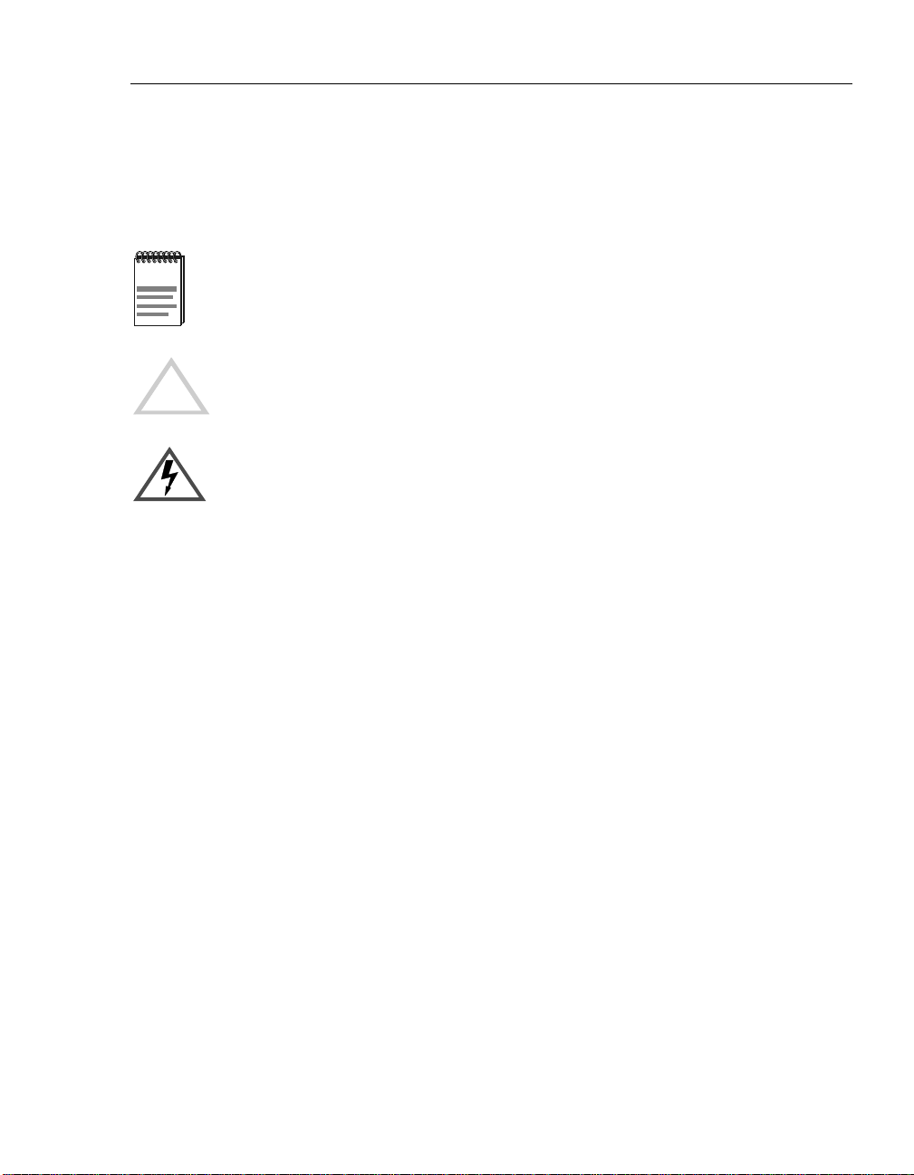
Document Conventions
Throughout this guide, the following symbols are used to call attention to important
information.
Note symbol. Calls the reader’s attention to any item of information that may be of
special importance.
Caution symbol. Contains information essential to avoid damage to the equipment.
!
Electrical Hazard W arning symbol. Warns against an action that could result in the
presence of an electrical hazard.
xv
Page 18

Preface
Glossary
This book uses the following terms:
Term Definition
Basic Rate A specific ISDN offering providing users with two
64Kb/s data channels (e.g. “B” channels) and one
16Kb/s signalling channel (e.g. “D” channel).
CLI Command Line Interface
Dedicated
Ethernet cable
DRS Distributed Routing Software
Ethernet A term used for product compatibility with ISO 8802-3/
SNMP Simple Network Management Protocol, an industry
SSR SmartSwitch Router
WAN Wide Area Network. A generic term used to identify
IEEE 10Base2 coaxial cable that carries Ethernet signals.
ANSI/IEEE 802.3 standards and the Ethernet standards
for CSMA/CD local area networks (LANs).
standard protocol for network management.
serial links which traverse large geographic areas.
xvi
Page 19

Getting Help
For additional support related to this device or document, contact the
Cabletron Systems using one of the following methods:
World Wide Web http://www.cabletron.com/
Phone (603) 332-9400
Internet mail support@cabletron.com
FTP ftp://ftp.cabletron.com/
Login
Password
To send comments or suggestions concer ning thi s documen t, co nta ct the Cabl etron
Systems Technical Writing Department via the following
email address: TechWriting@cabletron.com
Make sure to include the document Part Number in the email message.
Before calling Cabletron Systems, have the following information ready:
• Your Cabletron Systems service contract number
Preface
anonymous
your email address
• A descrip tion of the failure
• A description of any action(s) already taken to resolve the problem (e.g.,
changing mode switches, rebooting the unit, etc.)
• The serial and revision numbers of all involved Cabletron Systems
products in the network
• A description of your network environment (layout, cable type, etc.)
• Network load and frame size at the time of trouble (if known)
• The device history (i.e., have you returned the device before, is this a
recurring problem, etc.)
• Any previous Return Material Authorization (RMA) numbers
xvii
Page 20

Page 21

Product Introduction
Overview
This chapter provides a description of the SmartSwitch Router 510 and
SmartSwitch Router 520 (also referred to in this manual as SSR-510 and
SSR-520) and their features.
Chapter Contents
Topic Page
Chapter 1
What Are the SmartSwitch Router 510 and SmartSwitch Router
520?
SSR-510 Router 1-2
SSR-520 Router 1-2
Features 1-3
Performance and Memory 1-3
Configuration and Management 1-3
EasyStart 1-4
Front and Back Panel Components 1-5
Front Panel Components 1-5
Back Panel Components 1-8
1-2
1-1
Page 22

Product Introduction
What Are the SmartSwitch Router 510 and SmartSwitch Router 520?
The SmartSwitch Router SSR-510 and SmartSwitch Router SSR-520 (also
referred to in this manual as the SSR-510 and SSR-520 routers) provide
multiprotocol routin g for linking Ethernet LA Ns to corporate Wide Area
Networks (WAN).
The routers offer fle xi ble sof twa re s uppo rt tha t ca n be tai lo re d to t he n eeds of
specific remote environments.
The SSR-510 and SSR-520 routers are ava ilable with Multi protocol Softwa re.
Protocol support, for your package, is described in the Cabletron Distributed
Routing Software Release Notes.
The SSR-510 and SSR-520 standards-compliant technology ensures
interoperability in multivendor netwo rks.
SSR-510 Router
The SSR-510 router has the following port connections:
• One Ethernet interface, in either dedicated Ethernet (10Base2) or twisted
pair (10BaseT)
• One synchronous serial WAN port capable of T1/EI data rates
• One ISDN b asic rate interface (BRI) S/T-interface
SSR-520 Router
The SSR-520 router has the following port connections:
• One Ethernet interface, in either dedicated Ethernet (10Base2) or twisted
pair (10BaseT)
• Two synchronous WAN ports capable of T1/EI rates
1-2
Page 23

Features
The SSR-510 and SSR-520 routers include the following features.
Performance and Memory
The SSR-510 and SSR-520 ro uters contain the following perf ormance and
memory features:
• Industry-standard processors operating at 22.5 MHz clock rates, and
utilizes 32-bit address and data buses for maximum bus bandwidth.
• 4 MB of system flash memory.
• 4 MB of system memory using PC compatible memory DSIMMS.
• Memory accesses are parity protected on a byte wide basis.
Configuration and Management
Product Introduction
The following configuration and management options are available:
• Support for the following configuration options:
–– EasyStart configuration loader
–– Graphical User Interface (GUI) using the clearVISN Router
Configurator tool
–– Command Line Interface (CLI) using the console port
–– CLI using Telnet
• Upgradeable device firmware (in nonvolatile Flash memory) using
Trivial File Transfer Protocol (TFTP).
• Simple Network Management Protocol (SNMP) for monitoring.
1-3
Page 24

Product Introduction
EasyStart
EasyStart is a feature tha t allows you to downlin e load confi gurat ion file s
that are stored on a server via BOOTP/TFTP.
Using EasyStart and the clearVISN Router Configurator eliminates the
need for configuring the router using the Command Line Interface (CLI).
When the router is booted, it autoconfigures all interfaces and sends out
requests to load its configuration file. Once the file is received, the router
automatically res tarts so that th e configur atio n parameter s specif ied in t he
file take effect.
Refer to the SmartSwitch Router 500 Series System Software Guide fo r
information about using the EasyStart feature.
1-4
Page 25
Front and Back Panel Components
The following sections describe the front and back panel components for the
SSR-510 or SSR-520 routers.
Front Panel Components
Table 1-1 describes the front panel components, including LEDs, that are
illustrated in Figure 1-1.
For problem-solving information using the LEDs, refer to Appendix A.
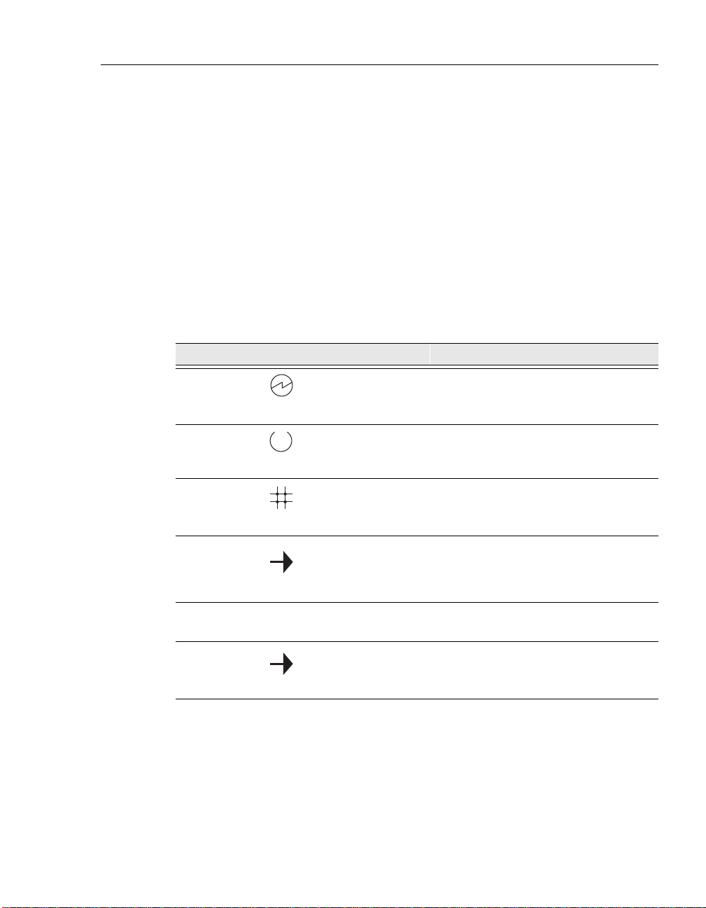
Table 1-1. Front Panel LEDs and Connectors
Item Icon Name Description
1 Power LED Lights when the router has power.
2 Module OK LED Lights when the router passes self-
test.
Product Introduction
3 Network OK LED Indicates network connection or port
state.
4 Network Activity
LED
5 Port 1 Serial Line
OK LED
6 Port 1 Serial Line
Activity Indicator
Indicates network traffic connection.
Blinks faster as traffic becomes
heavier.
Indicates self-test pass or failure.
Indicates operation mode on port 1.
Continued on next page ...
1-5
Page 26

Product Introduction
Item Icon Name Description
Table 1-1. Front Panel LEDs and Connectors
7 Port 2 Serial Line
OK LED (for
SSR-520)
ISDN Port OK
(for SSR-510)
8
Port 2 Serial Line
Activity Indicator
(for SSR-520)
ISDN Activity
Indicator (for
SSR-510)
9 Twisted Pair
(10BaseT)
Connector
10 Synchronous
Serial Port
Connectors
(labeled 1 and 2
for SSR-520)
11 Console Port
Connection
Indicates self-test pass or failure.
Indicates self-test pass or failure.
Indicates operation mode on port 2.
Indicates operation mode on ISDN
port.
Connects the router to a 10BaseT
network.
These ports support the EIA530A,
RS232/V.28, RS422/V.11, V.35, X.21
Leased Lines (LL), RS423/V.10
Connects a console terminal that is
used to manage the console. Uses an
8-pin MJ connector.
1-6
12 Dump Button Forces a dump of router memory.
Refer to the Distributed Router
Software System Software Guide for
more information.
13 Ethernet Network
Connector (BNC)
Connects the router to the dedicated
Ethernet segment. Not used when the
router is connected through the
twisted pair (10BaseT) connector.
14 Ethernet Label Lists the Ethernet address of the
module.
15 ISDN Connection
(labeled 2 for
Connects the module to an ISDN
segment. Uses an 8-pin MJ connector.
SSR-510)
Page 27
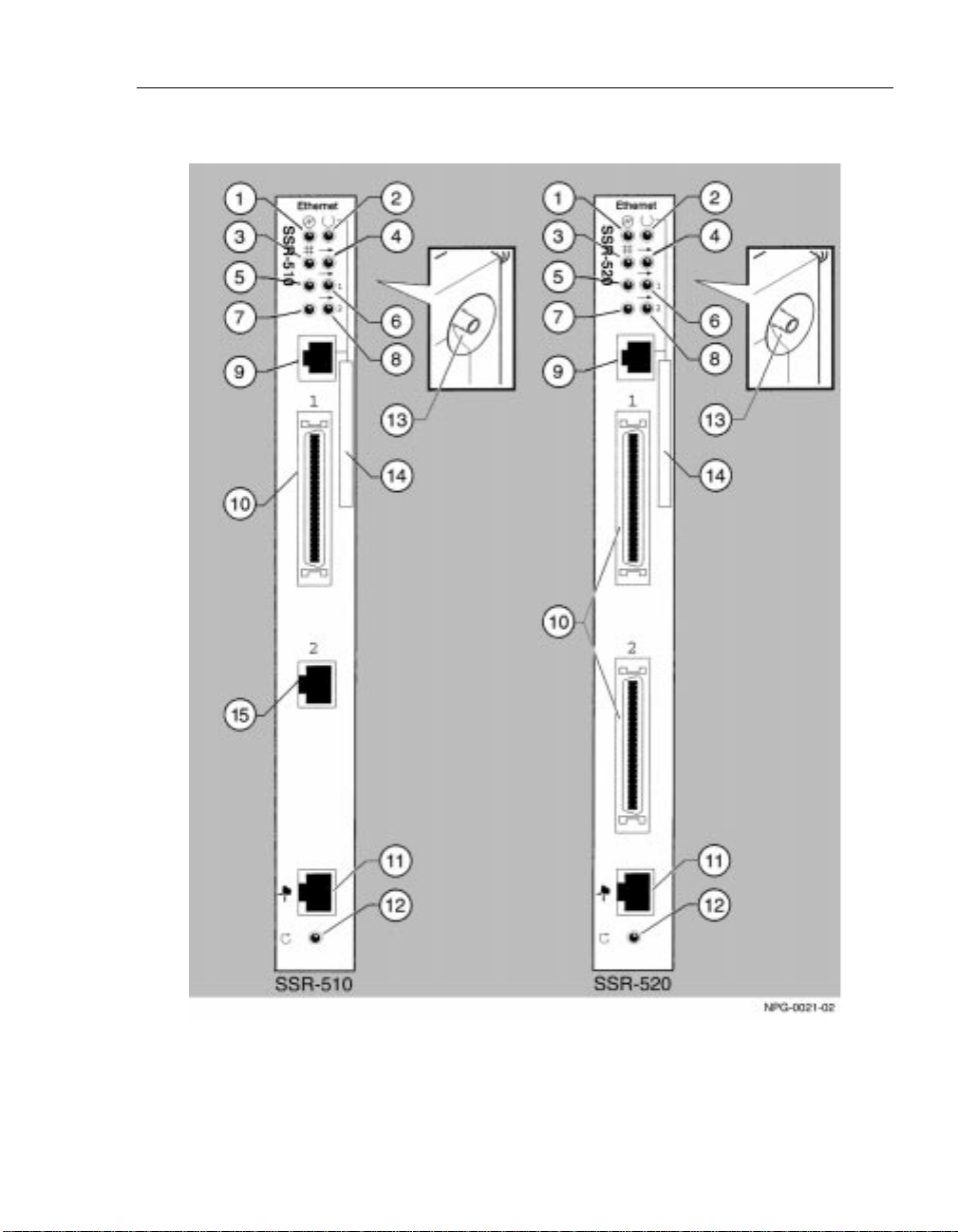
Figure 1-1. Front Panel LEDs and Connectors
Product Introduction
1-7
Page 28

Product Introduction
Back Panel Components
Table 1-2 describes the back panel components that are illustrated in
Figure 1-2.
Table 1-2. Back Panel Feature Components
Item Name Description
1 Power Connector Receives dc current from the power supply.
1-8
Page 29
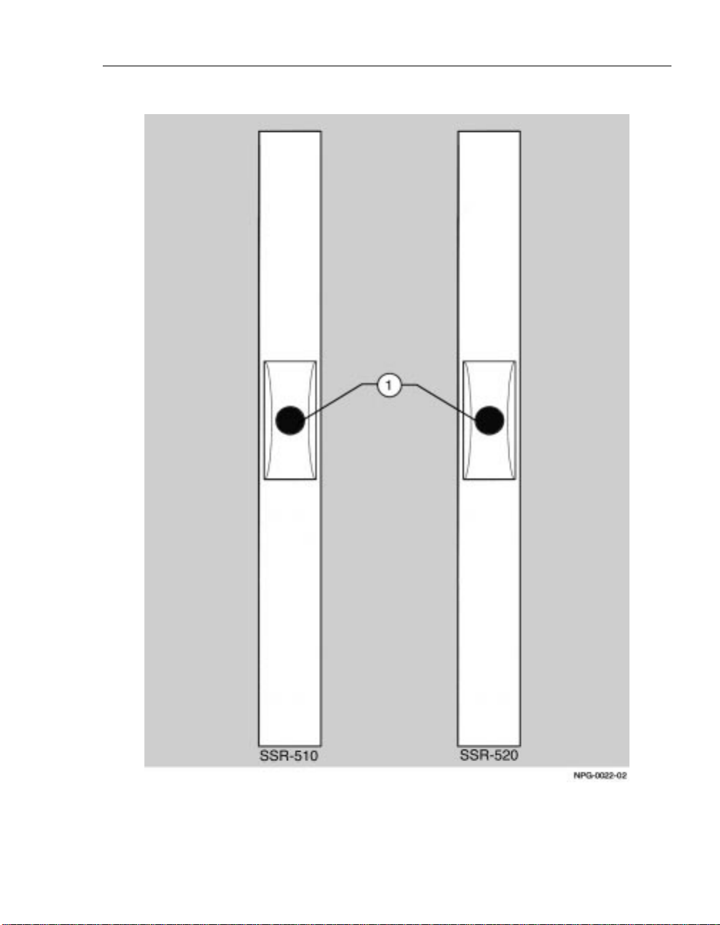
Figure 1-2. Back Panel Layout
Product Introduction
1-9
Page 30

Page 31

Installing and Cabling
Overview
This chapter describes how to install the SmartSwitch Router 510 and
SmartSwitch Router 520 in a rack mount shelf and how to cable the routers.
Chapter Contents
Topic Page
Installing the Router in the Rack Mounting Shelf 2-2
Cabling the Routers 2-6
Chapter 2
Removing the Cables 2-10
2-1
Page 32

Installing and Cabling
Installing the Router in the Rack Mounting Shelf
Either the SSR-510 or the SSR-520 router can be used as a standalone device
mounted on a wall or installed in a standard 19-inch rack using a shelf
assembly (Part Number H9544-MS).
Figure 2-1 shows the RETMA standard mounting shelf (1) that is used to
mount routers into a standard 19-inch rack. This shelf provides support for
one router (2) and one power supply unit (3). The shelf is attached to a rack
via rack mounting brackets (4). The router is secured to the shelf usi ng
adhesive strips (5). All routers with T-type dedicated Ethernet connectors on
the top, require 2-1/2 inches of vertical mounting space. Installation
instructions follow this figure.
Figure 2-1. Rack Mounting Shelf, Router and Power Supply Assembly
2-2
Page 33

Assembling the Rack Mount Shelf
Figure 2-1 shows the rack mount shelf. The following table provides
installation instructions.
Step Action
Installing and Cabling
1
2 Go to the section titled Assembling Adhesi ve Strips.
Attach two rack mount brackets (4) to the base (1) using four flat
headed #6-32 screws (see Figure 2-1).
The brackets can be attached in two positions flush or receded.
2-3
Page 34

Installing and Cabling
Attaching Adhesive Strips
To secure the router and power supply to the shelf, use eight inches of duallock reclosable fastening strip, (supplied with this kit). To assemble the
adhesive strips, complete the following steps.
Step Action
1
2 Peel off the liner to expose adhesive surface.
3 Apply strips to one side of th e router (about 1/2 inch from the end)
4 Mount the router to the tray and press down until an audible snap
5 After the router is mounted, connect cables as described in the
Cut three strips for the router (approximately 2 x 2-1/2 inches) and
one strip for the power supply (approximately 1 x 1-1/2 inches).
and to the shelf.
Notes: 1. Temperature should be above 68 degrees.
2. Surfaces must be clean, dry and free of oil.
3. Do not touch the adhesive after liner is removed.
However the shelf with the router can be handled
immediately.
is heard. Figure 2-2 shows an assembled unit.
section titled Cabling the Routers.
2-4
Page 35

Installing and Cabling
Figure 2-2. Assembled Router and Rack Mount Shelf
2-5
Page 36

Installing and Cabling
Cabling the Routers
This section describes how to cable the SSR-510 and SSR-520 routers.
Cabling the SSR-510
Figure 2-3 shows the SSR-510 router and cables. Cabling instructions follow
the figure.
Figure 2-3. Installing the SSR-510 Router
2-6
Step Action
1 Connect the cable from the power supply to the power connector
(1) on the back of the router.
Page 37

Step Action
Installing and Cabling
2
3
4
Plug the ac power supply cable (2) into the power supply, then
into a wall outlet.
Upon receiving power, verify that the router’s Power LED lights
immediately, that the Module OK LED lights within five seconds,
and that the router performs a self-test.
Note: The self-test requires 25 seconds to complete.
After the router completes self-test, and if the router is
unconfigured, the Power, Module OK, and Network OK LEDs
remain lit. The Network Activity LED blinks at a rate proportional
to the amount of activity on the port.
Note: If the LEDs do not op erate as described, refer to Appendix A.
Connect the dedicated Ethernet T-connector (3) OR the Twisted
Pair Connector (4):
a) Attach the dedicated Ethernet T-connector (3) to the BNC
network connector and turn the connector one-quarter turn
clockwise until it locks into place. Terminate the connection
with a 50-ohm terminator or extend the Ethernet segment to
the next device.
To disconnect the dedicated Ethernet T-connector, turn the
connector one-quarter turn counter-clockwise until the
connector clears the BNC connector stem, then disconnect
the cable.
b) OR, connect the 10BaseT cable (4) to the twisted pair
connector (8-pin MJ Ethernet connector).
Note: Do not use both dedicated Ethernet and twisted pair
connectors simultaneously.
5
6
7
8 After successful installation and power-up, configuration
Connect the ISDN cable (5) to Port 2 of the router.
Connect the serial cable (6) to Port 1 on the SSR-510 router.
Connect the console cable (7) using the 8-pin MJ connector. Use
an H8584-AC adapter if necessary.
information will display on the console monitor, including
questions about your network topology.
2-7
Page 38

Installing and Cabling
Cabling the SSR-520
Figure 2-4 shows the SSR-520 router and cables. The table following the
figure describes how to cable the router.
Figure 2-4. Installing the SSR-520 Router
2-8
Step Action
1
2 Plug the ac power supply cable (2) into the power supply, then
Connect the cable from the power supply to the power connector
(1) on the back of the router.
into a wall outlet.
Page 39

Step Action
Installing and Cabling
3
4
Upon receiving power, verify that the router’s Power LED lights
immediately, that the Module OK LED lights within five seconds,
and that the router performs a self-test.
Note: The self-test requires 25 seconds to complete.
After the router completes self-test, and if the router is
unconfigured, the Power, Module OK, and Network OK LEDs
remain lit. The Network Activity LED blinks at a rate proportional
to the amount of activity on the port.
Note: If the LEDs do not op erate as described, refer to Appendix A.
Connect the dedicated Ethernet T-connector (3) OR the Twisted
Pair Connector (4):
a) Attach the dedicated Ethernet T-connector (3) to the BNC
network connector and turn the connector one-quarter turn
clockwise until it locks into place. Terminate the connection
with a 50-ohm terminator or extend the Ethernet segment to
the next device.
To disconnect the dedicated Ethernet T-connector, turn the
connector one-quarter turn counter-clockwise until the
connector clears the BNC connector stem, then disconnect
the cable.
b) OR, connect the 10BaseT cable (4) to the twisted pair
connector (8-pin MJ Ethernet connector).
Note: Do not use both dedicated Ethernet and twisted pair
connectors simultaneously.
5
6
7
Connect the serial cables (6) to Port 1 and Port 2 on the SSR-520
router.
Connect the console cable (5) using the 8-pin MJ connector. Use
an H8584-AC adapter if necessary.
After successful installation and power-up, configuration
information will display on the console m on itor, including
questions about your network topology.
2-9
Page 40

Installing and Cabling
Removing the Cables
This section describes how to remove cables attached to the SSR-510 and
SSR-520 routers.
Removing the SSR-510 Cables
To remove cables from the SSR-510 router, see Figure 2-5 and complete the
following steps.
Step Action
1
2
3
Press the release tab (1) on the cabl e plug, then pull out the cable .
Push in the release tabs (2) on the side of the WAN serial cable
connector, then pull out the cable.
Press the release ta b (3) on t he ISDN cable plug, then pull out the
cable.
Figure 2-5. Removing the SSR-510 Cables
2-10
Page 41

Removing the SSR-520 Cables
To remove cables from the SSR-520 router, see Figure 2-6 and complete the
following steps.
Step Action
1
2
Press the release tab (1) on the cable plug, then pull out the
cable.
Push in the release tabs (2) on the side of the WAN serial cable
connector, then pull out the cable.
Figure 2-6. Removing the SSR-520 Cables
Installing and Cabling
2-11
Page 42

Page 43

Chapter 3
Connecting the Console Port
Cable
Overview
This chapter describes how to connect the SmartSwitch Router 510 or
SmartSwitch Router 520 router to the console port.
Chapter Contents
Topic Page
Signaling Stand ards 2-2
Console Port Device Cabling 2-2
Connecting the Console Port 2-3
3-1
Page 44

Connecting the Console Port Cable
Signaling Standards
The router console port confor ms to the EIA-232D s ignal ing standa rd at 9 600
baud. T o th e user, the port appears as a data termi nal e quipment (DTE) d evice.
Console Port Device Cabling
The console port can be connected to a console port device (a terminal or
personal computer), using the following cables and adapters:
If the console port device is a ... Use this
PC with a 9-pin D-Sub communi cations
port
Te rminal with a 25-pi n D-Sub connector BN24H-xx
Terminal with a 6-pin MMJ co nnector BN24H-xx
1
xx indicates cable length in meters.
cable...
BN24H-xx
1
1
1
With this
adapter...
H8571-J
H8575-A
Not required.
3-2
Page 45

Connecting the Console Port Cable
Connecting the Console Port
The console port connection is made through the console port on the router.
T o connect t he console por t on the SSR-510 or th e SSR-520 router s, complete
the following steps:
Step Action
1
2
Ensure that the transmit and receive baud rates on the console port
device are set to 9600 baud.
Connect the console port device to the console port connector on
the router.
The router’s console port is shown in Figure 3-1. The legend identifying the
console port cabling follows the figure.
3-3
Page 46

Connecting the Console Port Cable
Figure 3-1. Console Port Cabling Components
3-4
Item Description
1
2
Console Port Device
Console Port
After all cables are connected, go to Chapter 4, Configuring the Router.
Page 47

Configuring the Router
Overview
There are t wo ways to configure the router. The first and recommended way
is to invoke the clearVISN Router Configurator. The clearVISN Router
Configurator creates a configuration for the router. It allows the Router
Configurator and EasyStart to load that configuration into the router. The
second way is to manually configure the router using menus and the
Command Line Interface (CLI).
Examples of the setup screen displ ays are pr ovided in this sect ion to ai d in the
description of the console port and to display the options that are available.
Because they are exampl es only, the displays can vary s lightly from the a ctual
screen displays on your console port device. Boldface type in the screen
display examples indicates user input.
Chapter 4
Chapter Contents
Topic Page
Using the Router Configurator to Configure the Router 4-2
Using the CLI to Manually Configure the Router 4-6
Using Menus to Set up the Router 4-10
4-1
Page 48

Configuring the Router
Using the Router Configurator to Configure the Router
The following steps are requ ir ed t o conf igure your router with the clearVISN
Router Configurator.
Step Action
1
2
3
4
5
Install the clearVISN Router Configurat or on the PC that you plan to use
for configuring th e rout ers on yo ur network . The so ftware can be foun d
on the CD that accompanies the hardware.
Start the clearVISN Router Configurator and prepare your
configuration. For additional information on the clearVISN Router
Configurator, please refer to the clearVIS N Router Confi gurator User’s
Guide.
After your configuration is complete, you must start the BOOTP server
on your PC. The BOOTP server is on the START-PROGRAMSclearVISN Router Configurator program group.
If your router is direct from the factory and never had a configuration
loaded into it, it is now ready to perform the EasyStart function.
If your router has a configuration in it that you want to override, you
must re-initialize it to factory defaults before EasyStart can facilitate
loading the new configuration from the clearVISN Router Configurat or .
If you are configuring the router in a LAN environment, you can now
connect it to the same network as your PC and power it up.
If you are going to load your router over a wide-area network, refer to
the clearVISN Router Configurator User’s Guide for more information
on how to configure it in that environment.
4-2
Page 49

Step Action
Configuring the Router
6
After the router is powered up, you can verify that it is configured by
connecting to it via the console port or TELNET. The console port will
display the In-band management address that yo u selected on its menu
display.
If you successfully connect to the router with PING or TELNET, your
configuration has been successfully loaded.
Examples used in this section show a router power up when the system is
started with factory defaults.
The term “SmrtSwtch Rtr 5xx” is used to imply either the SmartSwitch
Router SSR-510 or the SmartSwitch Router SSR-520. Screens used in this
chapter reflect typical SSR-510 screens. These screens are very similar to
those used for the SSR-520.
4-3
Page 50

Configuring the Router
Console Screens
After the configuration exists in the cle arVISN Router Configurator, for new
routers, the followi ng scree ns show the power -up sequ ence of the router being
loaded by EasyStart:
SmrtSwtch Rtr 5xx
===============================================================
SmrtSwtch Rtr 5xx INSTALLATION MENU
* * * * * * * * * * * * * * * * * * * * * * * * * * * * * * *
To fully manage this device telnet to one of the
following IP addresses or select item [3] below.
Out-of-Band: Not Configured
In-Band : None Operational or Configured
* * * * * * * * * * * * * * * * * * * * * * * * * * * * * * *
[1] Restart with Factory Defaults
[2] Restart with Current Settings
[3] Go to Local Console
==================================================================
Enter selection : 00:00:05 EZ.001: Starting.
00:00:06 EZ.007: Waiting up to 6 seconds for devices to pass self-test.
00:00:08 AI.001: Changed params on ifc 1 (Serial Datalink),
from PSL to Frame Relay.
00:00:08 EZ.002: Changed one or more cfg params.
00:00:08 BTP.010: net 0, int Eth/0, Sent client request (htype: 1)
00:00:08 BTP.011: net 1, int SL/0, Could not snd client req because: Ifc not up
00:00:08 BTP.011: net 2, int ISDN/0, Could not snd client req because: Ifc type not suptd
00:00:08 BTP.007: net 0, int Eth/0, Valid Resp,
Server: Unknown(130.130.130.28),
Bootfile: C:\Program Files\Cabletron\RConfig\DRS\rf10935f.drs.SRM
VendOpts config file: None
IpAddr 100.100.100.47, gwAddr 0.0.0.0
00:00:08 BTP.012: net 0, int Eth/0 No cfile in vendOptions, using bootfile fld instead
00:00:08 EZ.004: Rcvd boot info: ipAddr 100.100.100.47,
ipMask 255.255.255.0 on intf 0
00:00:08 EZ.009: *** Restarting Router ***
4-4
Continued on the next page . . .
Page 51

Configuring the Router
SmrtSwtch Rtr 5xx
=====================================================================
SmrtSwtch Rtr 5xx INSTALLATION MENU
* * * * * * * * * * * * * * * * * * * * * * * * * * * * * * *
To fully manage this device telnet to one of the
following IP addresses or select item [3] below.
Out-of-Band: Not Configured
In-Band : 100.100.100.47
* * * * * * * * * * * * * * * * * * * * * * * * * * * * * * *
[1] Restart with Factory Defaults
[2] Restart with Current Settings
[3] Go to Local Console
====================================================================
Enter selection : 00:00:05 EZ.001: Starting.
00:00:06 EZ.007: Waiting up to 6 seconds for devices to pass self-test.
00:00:08 TFTP.025: Starting tftp of file C:\Program Files\Cabletron\RConfig\DRS\rf10935f.
drs.SRM from 100.100.100.28
00:00:08 TFTP.027: Transfer completed successfully.
Writing to NVRAM.
00:00:08 TFTP.028: Writing to NVRAM completed.
00:00:08 EZ.008: TFTP transfer completed successfully.
*** EasyStart Completed Successfully ***
00:00:08 EZ.009: *** Restarting Router ***
SmrtSwtch Rtr 5xx
====================================================================
SmrtSwtch Rtr 5xx INSTALLATION MENU
* * * * * * * * * * * * * * * * * * * * * * * * * * * * * * *
To fully manage this device telnet to one of the
following IP addresses or select item [3] below.
Out-of-Band: Not Configured
In-Band : 100.100.100.47
* * * * * * * * * * * * * * * * * * * * * * * * * * * * * * *
[1] Restart with Factory Defaults
[2] Restart with Current Settings
[3] Go to Local Console
====================================================================
Enter selection :
The router has been configured and is now ready to be used on the network.
4-5
Page 52

Configuring the Router
Using the CLI to Manually Configure the Router
When you power-up a router set with factory defaults, it will automatically
enter the EasyStart process.
To stop the EasyStart proc ess, press <Enter> during the EZ.xxx messages.
The router will restart. Upon restart, use option
Console
type Stop quickly at the EasyStart prompt. The router will then restart and
allow access for creating the configuration manually.
If you plan to use Telnet to access the router, you must assign an IP address.
This is accomplished b y selecting e ither
Go to Local Console
INSTALLATION MENU. The following table describes where to locate th e
configuration instructions.
If you will use the console terminal port to access the router for manual
configuration, the SmrtSwtch Rtr 5xx INSTALLATION MENU will
display. Select either option
address on the Ethernet i nt erf ace or option
to configure the router using qconfig (quick configuration tool).
from the SmrtSwtch Rtr 5xx INSTALLATION MENU and
[4] IP Configuration
from the SmrtSwtch Rtr 5xx
[4] IP Configuration
[3] Go to Local
to configure the I P
[5] Go to Local Console
or
[5]
4-6
Examples used in this section show a router power up when the system is
started with factory default settings.
The term “SmrtSwtch Rtr 5xx” is used to imply either the SmartSwitch
Router SSR-510 or the SmartSwitch Router SSR-520.
This section assumes this is the initial configuration of the router. To verify if
the router is configur ed, observe option
at the SmrtSwtch Rtr 5xx INSTALLATION MENU to see if an InBand address displays. If no addres s displays, or you see option [5 ] Go to
Local Console in the SmrtSwtch Rtr 5xx INSTALLATION
MENU the router is not configured. You can create a configuration with the
clearVISN Router Configurator as explained previously or manually
configure the router using the CLI.
After 5 seconds, if the router is not configured, the system displays the
following dialog.
[3] Show Current Settings
Page 53

Configuring the Router
After the SmrtSwtch Rtr 5xx INSTALLATION MENU displays twice,
type 3 and press <Return> as shown in the following example:
Will start FLASH GW image in 5 seconds
Hit <ctl>C or enter cmd with <CR> to abort
Digital RouteAbout Access EW bootstrap monitor V1.0 [Jul 5 1995]
Copyright (C) 1995, Digital Equipment Corporation
>
SmrtSwtch Rtr 5xx
====================================================================
SmrtSwtch Rtr 5xx INSTALLATION MENU
* * * * * * * * * * * * * * * * * * * * * * * * * * * * * * *
To fully manage this device telnet to one of the
following IP addresses or select item [3] below.
Out-of-Band: Not Configured
In-Band : None Operational or Configured
* * * * * * * * * * * * * * * * * * * * * * * * * * * * * * *
[1] Restart with Factory Defaults
[2] Restart with Current Settings
[3] Go to Local Console
====================================================================
Enter selection : 00:00:05 EZ.001: Starting.
00:00:06 EZ.007: Waiting up to 30 seconds for devices to pass self-test.
00:00:08 AI.001: Changed params on ifc 1 (Serial Datalink),
from PPP to PSL.
00:00:08 EZ.002: Changed one or more cfg params.
00:00:08 BTP.010: net 0, int Eth/0, Sent client request (htype: 1)
00:00:08 BTP.011: net 1, int PPP/0, Could not snd client req because: Ifc not up
00:00:08 BTP.011: net 2, int ISDN/0, Could not snd client req because: Ifc type not suptd
00:00:09 BTP.010: net 0, int Eth/0, Sent client request (htype: 1)
00:00:09 BTP.011: net 1, int PPP/0, Could not snd client req because: Ifc not up
00:00:09 BTP.011: net 2, int ISDN/0, Could not snd client req because: Ifc type not suptd
00:00:10 BTP.010: net 0, int Eth/0, Sent client request (htype: 1)
00:00:10 BTP.011: net 1, int PPP/0, Could not snd client req because: Ifc not up
00:00:10 BTP.011: net 2, int ISDN/0, Could not snd client req because: Ifc type not suptd
00:00:13 EZ.003: Bootp failed.
00:00:13 EZ.006: All dlinks/parameters tried but failed; resetting to def values.
00:00:13 EZ.009: *** Restarting Router ***
SmrtSwtch Rtr 5xx
====================================================================
SmrtSwtch Rtr 5xx INSTALLATION MENU
* * * * * * * * * * * * * * * * * * * * * * * * * * * * * * *
To fully manage this device telnet to one of the
following IP addresses or select item [3] below.
Out-of-Band: Not Configured
In-Band : None Operational or Configured
* * * * * * * * * * * * * * * * * * * * * * * * * * * * * * *
[1] Restart with Factory Defaults
[2] Restart with Current Settings
[3] Go to Local Console
====================================================================
Enter selection : 3 <Return> 00:00:05 EZ.001: Starting.
4-7
Page 54

Configuring the Router
After the Easy Star t> prompt displa ys, quic kly type : stop and press <Retur n>
Copyright (c) 1998, Cabletron Systems Inc.
MOS Operator Control
Entering EasyStart operation. Type ‘stop’ to terminate.
ELS messages are automatically displayed in this mode.
EasyStart> Stop <Return>
SmrtSwtch Rtr 5xx
=============================================================
SmrtSwtch Rtr 5xx INSTALLATION MENU
[1] Restart with Factory Defaults
[2] Restart with Current Settings
[3] Show Current Settings
[4] IP Configuration
[5] Go to Local Console
=============================================================
Enter selection:
T o access the se tup menus, press t he <Return> key on the consol e port device
until the SmrtSwtch Rtr 5xx INSTALLATION MENU displays.
4-8
To configure the router using Go to the section titled
Menus
Using Menus to Set up the Router
(assign IP Address via menus)
Commands
Go to Local Console
(assign IP Address via the CLI
qconfig procedure)
Page 55

Preconfigured Router Screen
If the router was previously configured, the following menu items are
available.
If you press the <Return> key during the bootstrap operation, execute the
stored image by typing e at the > prompt.
SmrtSwtch Rtr 5xx
==================================================================
SmrtSwtch Rtr 5xx INSTALLATION MENU
*****************************************************************
To fully manage this device telnet to one of the
following IP addresses or select item [3] below.
Out-of-Band: Not Configured
In-Band : 134.1.147.150
*****************************************************************
[1] Restart with Factory Defaults
[2] Restart with Current Settings
[3] Go to Local Console
=========================================================
Enter selection :
Configuring the Router
4-9
Page 56

Configuring the Router
Using Menus to Set up the Router
This section describes the options that are available from the SmrtSwtch
Rtr 5xx INSTALLATION MENU.
Option Page
[1] Restart with Factory Defaults
[2] Restart with Current Settings
[3] Show Current Settings
[4] IP Configuration
[5] Go to Local Console
4-11
4-12
4-13
4-14
4-19
4-10
Page 57

[1] Restart with Factory Defaults
This option initializes the router’s configuration to factory default values by
resetting the router’s nonvolatile configuration storage parameters and
restarting the router. (To retain the current values, use Option [2]
Restart with Current Settings.) Allow up to one minute for the
router to restart.
This action deletes all configured settings and replaces them with factory
!
CAUTION
default values. All configuration settings will be lost.
The following example shows the dialog associated with this selection.
Enter selection : 1
SmrtSwtch Rtr 5xx
==========================================================
Configuring the Router
RESTART WITH FACTORY DEFAULTS
* * * * * * * * * * * * * * * * * * * * * * * * * * * * *
* IMPORTANT! IMPORTANT! IMPORTANT! *
* * * * * * * * * * * * * * * * * * * * * * * * * *
* This selection will delete the current configuration *
* settings and reset the system with the factory default
* settings. All configuration settings will be lost. *
* * * * * * * * * * * * * * * * * * * * * * * * * * * * *
==========================================================
Press Y to confirm [N]: Y <Return>
Press Return for Main Menu...
* * *
*
After you press <Return>, the EasyStart rebooting feature becomes active.
The EasyStart feature allows the router to boot up using existing
configuration files. EasyStart messages will appear on the console device.
Refer to the SmartSwitch Router 500 Series System Software Guide and the
clearVISN Router Configurator User’s Guide for more information about the
EasyStart feature.
4-11
Page 58

Configuring the Router
[2] Restart with Current Settings
This option restarts the router but leaves the router’s configured nonvolatile
configuratio n storage parameters at the ir current valu es.
The following example shows the dialog associated with this selection.
Enter selection: 2
SmrtSwtch Rtr 5xx
=============================================================
RESTART WITH CURRENT SETTINGS
This selection will restart your system with the current
configuration settings.
=============================================================
Press Y to confirm [N] : Y <Return>
Press Return for Main Menu...
If you select Y, then the SmrtSwtch Rtr 5xx INSTALLATION MENU
will redisplay.
4-12
Page 59

[3] Show Current Settings
This option shows the router’s current settings. If the router is being
configured for the first time, some of the fields will be blank.
The following example shows the screen display associated with this
selection.
Enter selection : 3
SmrtSwtch Rtr 5xx
===============================================================
SmrtSwtch Rtr 5xx,Brouter:1 Enet 1T1 1BRI,HW=1,RO=1,#4105,SW=v3.0-3
SysUpTime : 00:07:22 23 resets
SNMP Read/Write Community : Not Available
Default Gateway : Not Configured
Configuring the Router
Interface
Ethernet 134.1.147.150 255.255.255.0
===============================================================
... Press Return to continue ...
SmrtSwtch Rtr 5xx
===============================================================
===============================================================
Press Return for Main Menu ...
IP Address Subnet Mask Other Info
4-13
Page 60

Configuring the Router
[4] IP Configuration
The IP Configuration option provides you with four selections.
The following example shows the menus available with this selection.
Enter selection : 4
SmrtSwtch Rtr 5xx
=========================================================
* * * * * * * * * * * * * * * * * * * * * * * * * * * *
* Configuration will not take effect until module *
* is restarted *
* * * * * * * * * * * * * * * * * * * * * * * * * * * *
[1] Set SNMP Read/Write Community
[2] Set In-Band Interface IP Address
[3] Set Default Gateway
[4] Return to Main Menu
===================================================
IP CONFIGURATION
Enter selection:
4-14
The following pages describe the IP Configuration options.
Option Page
[1] Set SNMP Read/Write Community 4-15
[2] Set In-Band Interface IP Address 4-16
[3] Set Default Gateway 4-17
Page 61

[1] Set SNMP Read/Write Community
This option prompts you to enter the router’s SNMP read/write community
name.
The following example shows the dialog associated with this selection.
Enter selection : 1
SmrtSwtch Rtr 5xx
================================================================
SET SMNP READ/WRITE COMMUNITY
Format: The format for a community name is a string,
consisting of 4 to 31 printable Ascii characters,
that describes the relationship between an SNMP
agent and one or more SNMP managers. The string
defines the authentication mechanism that is employed
to validate the use of the community by the sending
SNMP entity.
================================================================
Enter the community string [public] : public <Return>
SNMP Read/Write community string set.
Press Return for IP Configuration Menu...
Configuring the Router
4-15
Page 62

Configuring the Router
[2] Set In-Band Interface IP Address
This option prompts you to change or enter the IP address and subnet mask
for the in-band interface. You can only configure one in-band interface at a
time. The router does not ne ed to be con figured wi th a subnet mask for SNMP
communications when management stations are on the same subnet as the
router.
The format for these val ues is the standard 4- oct et dot ted decimal notation, in
which each octet of the addres s is represent ed as a decimal value, s eparated by
a decimal point (.).
The following example shows the dialog associated with this selection.
Enter selection 2
SmrtSwtch Rtr 5xx
=========================================================
IN-BAND INTERFACE IP ADDRESS CONFIGURATION
Format: The standard 4 octet dotted decimal notation in which
each octet of the address is represented as a decimal
value, separated by a "." character.
example: 134.12.13.14
======
4-16
To delete the IP address, enter 0 in the appropriate
address field.
Interface
Ethernet
================================================================
Enter the Subnet Mask [0.0.0.0] : 255.255.0 0 : <Return>
Press Return for IP Configuration Menu ...
IP Address Subnet Mask Other Info
Enter the IP address [] : 134.12.13.14 <Return>
Page 63

[3] Set Default Gateway
This option sets the default gateway, if necessary, for the in-band interface.
This is the address of a rou ter th at t h e r out er will use when communicating to
a remote host. The default gateway address must be an address in the same
subnet as your in-band address.
The following example shows the dialog associated with this selection.
SmrtSwtch Rtr 5xx
=========================================================
Format: The standard 4-octet dotted decimal notation in which
each octet of the address is represented as a decimal
value, separated by a "." character.
example: 134.12.13.14
To delete the address, enter 0 in the appropriate
address field.
========================================================
Default Gateway []: 126.43.24.10 <Return>
Default Gateway Address Set.
Press Return for IP Configuration Menu . . .
Configuring the Router
Enter selection : 3
SET IN-BAND INTERFACE DEFAULT GATEWAY ADDRESS
4-17
Page 64

Configuring the Router
Go to Local Console
This option allows you to configure the router.You must configure the router
before it is operational. The Go to Local Console option provides two
different configu ration methods, dep ending on whether the route r has been set
up with factory defaults or has been previously configured.
If the router has been set up with factory defaults, then select [5] Go to
Local Console in the SSR-5xx INSTALLATION MENU. This option
runs a quick configuration interactive question and answer dialog. This
method (qconfig) allows fast configuration of interfaces, basic bridging, IP,
IPX, IP Routing Protocols, DECnet and booting.
If the router has been previously configured, then select [3] Go to
Local Console in the installation menu. This option allows you to
configure the router using commands to configure interfaces, bridging, and
routing protocols (for example, IPX and IP).
4-18
Page 65

[5] Go To Local Console
This selection runs quick configuration. If you reset to factory defaults and
select Go to Local Console without having configured the router via
the installation menu, the qconfig process starts automatically.
After making the changes you want, exit quick configuration and apply the
changes you made by typing restart. The system displays the following
messages:
Quick Config Done
Type RESTART at Config (only)> prompt for the configuration to
take effect.
Config (only) >
If you type r estart at the Config (only)> prompt, the following message
displays:
Config (only)>restart
Are you sure you want to restart the gateway? (Yes [No]):
Configuring the Router
Enter yes to proceed. The following menu is then displayed.
SmrtSwtch Rtr 5xx
==================================================================
SmrtSwtch Rtr 5xx INSTALLATION MENU
**************************************************
To fully manage this device telnet to one of the
following IP addresses or select item [3] below.
Out-of-Band: Not Configured
In-Band : 134.1.147.150
**************************************************
[1] Restart with Factory Defaults
[2] Restart with Current Settings
[3] Go to Local Console
==================================================================
Enter selection :
4-19
Page 66

Page 67

Supporting ISDN for the SSR-510
Overview
This section describes SSR-510 support for ISDN. Before you begin to
configure your route r, you must make sure you have comple te d t he necessary
steps in obtaining ISDN support.
This chapter defines what you will need to do to obtain the proper ISDN
support. ISDN configuration information resides in the SmartSwitch Router
500 Series Network Interface Operations Guide.
Chapter 5
Chapter Contents
Topic Page
Ordering Your ISDN Line 5-2
Obtaining a Network Termination Device 5-3
5-1
Page 68

Supporting ISDN for the SSR-510
Ordering Your ISDN Line
You should order your basic rate ISDN service from your local telephone
company or PTT. When you order your ISDN service, request 64K circuit-
switched data on your “B” channels. The router does not support voice
services.
Table 5-1 lists the pos sible value for basic rate ISDN parameters. The
telephone company will provide you with the ISDN configuration parameter
settings for your service. You will need these to properly configure the router
for ISDN operation.
Table 5-1. Possible Values for ISDN Parameters
ISDN
Configuration
Parameter
Switch Type • INS64 (Japan)
TEI Usually has a default value of auto.
Local Number The number to call for your basic rate interface.
Directory
Number(s)
Possible Values
•VN3
•NET3
• AUSTEL - Australian Telecom TS.014
• 5ESS (AT&T custom for 5ESS local office exchange)
• DMS100 - Northern Telecom custom
• NI1 - National ISDN-1, deployed by several vendors on
their switches
Optional; these are normally the same as the Local Number
plus one alternate number that also reaches you.
5-2
Page 69

Supporting ISDN for the SSR-510
Obtaining a Network Termination Device
In the United States the telephone company provides you with a U-interface
connection. Because of this, you need a network termination device (NT1) to
convert the U-interface to the S/T-interface. In Europe and other parts of the
world, an NT1 is not required because an S/T-interface is provided.
The network termination device (NT1) provides network termination
functions to your basic rate interface (BRI) connection. The NT1 device
allows you to add S/T-interface devices to your ISDN connection.
Depending on your country, you may need an NT1 device to connect the
SSR-510 to your ISDN line. Check with your local telephone company or
your authorized Cabletron Systems reseller to see if they can provide one for
you.
Make sure the NT1 device you choose has the following items necessary to
connect the router to the ISDN line:
• Power supply, either integrated or separate.
• Cable to attach the NT1 device.
5-3
Page 70

Page 71

Problem Solving
Overview
This appendix describes the LED functions and provides problem solving
information. The LEDs on the front of the router, with this appendix, provide
information to help you correct possible problems.
Appendix Contents
Topic Page
Normal Powerup A-2
Self-Test Progress States A-3
Appendix A
LED Descriptions A-5
Problem Solving Using the LEDs A-7
A-1
Page 72

Problem Solving
Normal Powerup
When the router power is initially turned on, the following events occur:
Event Description
1
2
3
4
The router’s Power LED lights as soon as power is
applied to the unit.
The router initiates its built-in self-test. Flashing port serial
line LEDs and activity LEDs indicate that the router is
running various subr out ines as part of th e self-test. See Table
.
After successful completion of the self-test, the
Module OK LED lights, and remains lit.
The Network Activity LED blinks at a rate
proportional to the amount of activity on the port.
The remaining LEDs no w indi cate their oper ation al st atus , as
described in Table .
A-2
Page 73

Self-Test Progress States
Upon power up, the router immediately begins a sequence of self tests and
memory sizing. The following sequence of LEDs pass by so quickly that it is
difficult to identify the discrete steps on a functioning router.
Should a hardware fault be detected, the LEDs will reflect the progress made
into the self-t est . This information ca n be useful when desc ri bing problems to
your service representati ve.
These tests are run prior to the router OK LED being lit.
NOTE
Problem Solving
Table A-1 describes the router’s self-test progress LED states.
Table A-1. Router Self Test Progress LED States
1 2 3 4 5 6
1 0 000000Microprocessor test and register setup
1 0 G00001Microprocessor interrupts setup
1 0 G00010Option card microprocessor setup
1 0 G00011Option card interrupts setup
1 0 G00100Memory controller port and memory setup
1 0 G00101Peripheral controller port setup
1 0 G00110Option card port set up (if present)
1 0 G00111Restart configuration setup
1 0 G01000Memory controller dpram test
1 0 G01001Peripheral controller dpram test
Continued on the next page . . .
A-3
Page 74

Problem Solving
1 0 G01010Option card dpram setup (if present)
1 0 G01011Serial channel internal loopback test
1 0 G01100Debug console internal loopback test
1 0 0G0001Memory test setup
1 0 0 G 0 0 1 0 Bank 0 simm presence test
1 0 0 G 0 0 1 1 Bank 1 simm presence test
1 0 0G0100Test for no memory present
1 0 0G0101Test for simm size, bank 0
1 0 0G0110Test for simm size, bank 1
1 0 0G0111Re-map available memory
Table A-1. Router Self Test Progress LED States
1 2 3 4 5 6
A-4
1 0 0G1000Refresh test
1 0 0G1001DRAM array test
1 0 0 G 1 0 1 0 Save DRAM configuration and size
1 0 0 G 1 0 1 1 Set the stack pointer and jump to manufacturing
tests
1 = On, 0 = Off
G = On, Green
Page 75

LED Descriptions
The router’s LEDs prov ide dynamic indic ations of the stat us of the router. The
LEDs can be in various states (on, off, or flashing), and can change color
(green or yellow) depend ing on the operational status of the router or the level
of activity on the network.
Table A-2 shows the states that are possible for each of the router’s LEDs.
Table A-2. Router LED States After Self-Test Completion
Problem Solving
LED
Name
Power No power to
Module
OK
Network OKEthernet port is
Network
Activity
Serial
Line 1
OK
Off On (Green) Flashing
router
Self-test failed Router passed self-
not connected to a
properly
terminated and
operational LAN
No network
activity
Self-test failure Normal operation Self-test mode
Router receiving
power
test
Ethernet port is
connected to a
properly terminated
and operational LAN
Heavy traffic on
network
Faulty power
connection or
insufficient
power
N/A
N/A
Flashes more
rapidly and
appears brighter
as network traffic
increases
Continued on the next page . . .
A-5
Page 76

Problem Solving
Table A-2. Router LED States After Self-Test Completion
LED
Name
Serial
Line 1
Activity
Port 2
OK
Port 2
Activity
Off On (Green) Flashing
No traffic on the
port
There is traffic on the
port
Flashes more
rapidly and
appears brighter
as network traffic
increases
Self-test failure Normal operation Self-test mode
No traffic on the
port
There is traffic on the
port
Flashes more
rapidly and
appears brighter
as network traffic
increases
A-6
Page 77

Problem Solving Using the LEDs
When diagnosing a problem with the router, note that the problem is often
indicated by the states of the router’s LEDs. Table A-3 lists the states of the
LEDs for various error conditions that can occur during initial installation of
the device, along with probable causes and corrective actions to take.
Table A-3. LED States
Symptom Probable Cause Corrective Action
Problem Solving
All LEDs are
off.
Power LED only
is off.
Module OK
LED is off.
The router does not
have power.
Wrong power supply. Ensure to use only the
Bad Power LED. Replace the router.
Self-test failed. If the LED does not light after
Secure the power cables at the
back cover and between the
power supply and wall outlet.
Check the wall outlet using
another appliance or light, or
plug the power cord into
another outlet. If no power is
available, check the wall
outlet’s circuit breaker.
Replace the power supply or
the router if the problem
persists.
H8767-AA power supply.
5 seconds, reset the router to
repeat the self-test.
Check console and reload
flash.
If the self-test fails again,
replace the router.
Continued on next page ...
A-7
Page 78

Problem Solving
Symptom Probable Cause Corrective Action
Table A-3. LED States
Network OK
LED does not
stay on after the
functional code
begins
execution.
Network
Activity LED is
off.
Serial Port 1 or
Serial Port 2 OK
LED does not
stay on after the
functional code
begins
execution.
The network interface
self-test has failed.
There is low network
activity or no network
activity.
If the router is
connected to a known
active segment and the
Network Activity LED
is off, then the router is
defective.
Serial Port 1 or 2
interface self-test has
failed.
Refer to the SmartSwitch
Router 500 Series System
Software Guide to determine
the network interface status
and to display any logged
network interface events.
Ensure that there is network
activity. If the Network
Activity LED still fails to turn
on, then turn the unit off
momentarily by removing it
from the power supply. Check
that the Network Activity LED
blinks momentarily during the
LED powerup self test.
Replace the router.
Refer to the SmartSwitch
Router 500 Series System
Software Guide to determine
the serial port interface status
and to display any logged serial
port interface events.
A-8
Continued on next page ...
Page 79

Problem Solving
Table A-3. LED States
Symptom Probable Cause Corrective Action
Serial Port 1 or
Serial Port 2
Activity LED is
off.
Console
terminal does
not appear work.
There is low serial port
activity or no serial port
activity.
Ensure that serial port activity
is present. If the Serial Port
Activity LED still fails to turn
on, then turn the unit off by
removing it from the power
supply. Check that the Serial
Port Activity LED blinks
during the LED powerup selftest.
If the Serial Port Activity LED
blinks, then the Serial Port
Activity LED portion of testing
has passed. If the Serial Port
Activity LED still fails to turn
on, then the router is defective.
Ensure that the cable
Replace the router.
has activity on it. If the
LED still fails to turn
on, then the port is
defective.
Wrong cable. Try connecting the console
terminal to the router using a
null modem cable with the
appropriate 8-pin MJ RS232
connector on the router end.
Wrong baud rate. Send a BREAK to the console
and then press <Return>
several times until the console
responds. Proper baud rat es are
300, 1200, 2400, 4800, 9600,
19200, and 38400.
Defective router. Replace the router.
A-9
Page 80

Page 81

Appendix B
Connectors, Adapters and Cable Connections
Overview
This appendix shows detailed illustrations of the connectors, adapters, pin
assignments and cable connections used on the SSR-510 and the SSR-520.
Appendix Contents
Topic Page
Connector Assignments B-2
Adapters B-5
Cable Connections B-6
B-1
Page 82

Connectors, Adapters and Cable Connections
Connector Assignments
50-pin Serial Port Connector
Figure B-1 shows the 50-pin serial port connector and its pin assignments.
Table B-1 describes the pin assignments.
Figure B-1. 50-pin Connector
B-2
T able B-1. 50-pin Connector Assignments
Pin Assignment Pin Assignment
1
3N/C 4DSR A
5 TX Data A 6 DCD A
7 TX Data A 8 RTS A
9 CTS A 10 RX Data A
Code Ground
1
2Cable_ID<1>
Continued on the next page . . .
Page 83

Connectors, Adapters and Cable Connections
T able B-1. 50-pin Connector Assignments
Pin Assignment Pin Assignment
11 Ring Indicate 12 N/C
13 RX Clock A 14 DTR A
15 TX Clock A 16 N/C
17 TX Clock A 18 N/C
19 TX Clock A 20 LBK
21 V.35 TX Clock A 22 V.35 Clock A
23 V.35 RX Data A 24 V.35 TX Data A
25 V.35 RX Clock A 26 C able_ID<0>
27 Cable_ID<2> 28 N/C
29 DSR B 30 TX Data B
31 DCD B 32 RTS A
33 RTS B 34 CTS B
35 RX Data B 36 N/C
37
DTE Ground
1
38 RX Clock B
39 DTR B 40 TX Clock B
41 N/C 42 TX Clock B
43 N/C 44 DTR A
45 N/C 46 V.35 TX Clock B
47 V.35 Clock B 48 V.35 RX Data B
49 V.35 TX Data B 50 V.35 RX Clock B
1
Contacts tied together.
B-3
Page 84

Connectors, Adapters and Cable Connections
10BaseT Port (8-pin MJ) Connector
Figure B-2 shows the 8-pin MJ crossover connector and its pin assignments.
Table B-2 describes the pin assignments.
Figure B-2. 8-pin MJ Connector
Pin 1 8
T ab le B-2. 8-pin MJ Connector Assignments
Pin Assignment Pin Assignment
NPG-8719-95F
B-4
1 RX+ 5 Unused
2 RX- 6 TX3 TX+ 7 Unused
4 Unused 8 Unused
Page 85

Adapters
H8571-J Adapter
Figure B-3 shows the H8571 -J ada pte r (6- pi n MMJ con nec tor t o 9- pi n D-Su b
connector) and its pin assignments.
Connectors, Adapters and Cable Connections
Figure B-3. H8571-J Adapter
H8575-A Adapter
Figure B-4 shows the H8575-A adapter (6-pin MMJ connector to
25-pin D-Sub connector) and its pin assignments.
Figure B-4. H8575-A Adapter
B-5
Page 86

Connectors, Adapters and Cable Connections
Cable Connections
Tables B-3 through B-8 list the proper cable connections for the X.21,
EIA422, V.35, EIA530A, EIA423, and V.24/EIA232 standards.
Table B-3. X.21 Cable Connections (BC12F-06)
From Pin
Connector (P1)
1, 2, 26 –
To X.21 Pin
Connector (P2)
Signal Name
Code Ground
1
5 2 T(A) TX Data A
30 9 T(B) TX Data B
6 5 I(A) DCD A
31 12
I(B) DCD B
2
8 3 C(A) RTS A
33 10 C(B) RTS B
10 4 R(A) RX Data A
35 11
17
22
6
13
R(B) RX Data B
S(A) TX Clock A
S(B) TX Clock B
13, 15 - RX Clock A
DTE Clock B
1
38, 40 - RX Clock B
DTE Clock B
2
2
2
B-6
37 8 G DTE Ground
1
Contacts tied together.
2
120 OHM resistor, 1/2w between pins 6 and 31, 10 and 35, 17 and 42. The resistors are at
the P1 end of the cable.
Page 87

Connectors, Adapters and Cable Connections
Table B-4. EIA422/V.11/V.36 Cable Connections (BC12H–06)
From Pin Connector
(P1)
1, 27 –
To EIA422 Pin
Connector P2)
Signal Name
Code Ground
1
411DSR A
29 29 DSR B
5 4 TX Data A
30 22 TX Data B
613DCD/I A
31 31 DCD/I B
8 7 RTS/C A
33 25 RTS/C B
99CTS A
34 27 CTS B
10 6 RX Da ta A
35 24
RX Data B
2
11 15 Ring Indicate
12 20 DCE Ground
13 8 RX Clock A
38 26
RX Clock B
14 12 DTR A
39 30 DTR B
Continued on next page ...
2
B-7
Page 88

Connectors, Adapters and Cable Connections
Table B-4. EIA422/V.11/V.36 Cable Connections (BC12H–06)
From Pin Connector
(P1)
To EIA422 Pin
Connector P2)
Signal Name
15 17 Clock A
40 35 Clock B
17 5 TX Clock A
42 23
TX Clock B
2
18 18 Test Indicate
37 19, 37
DTE Ground
1
20 10 Local Loop
41 16 Speed Select
45 14 Remote Loop
Shell Shell Shield Braid
1
Contacts tied together.
2
120 OHM resistor, 1/2w between pins 10 and 35, 13 and 38, 17 and 42. The resistors
are at P1 end of cable.
B-8
Page 89

Connectors, Adapters and Cable Connections
Table B-5: V.35 Connection (BC12G-06)
From Pin Connector
(P1)
1, 26 –
To V.35 Pin
Connector (P2)
Signal Name
Code Ground
1
4EDSR A
6 F DCD/I A
9DCTS A
11 J Ring Indicate
21 Y TX Clock A
46 A TX Clock B
22 U Clock A
47 W Clock B
23 R RX Data A
48 T RX Data B
24 P TX Data A
49 S TX Data B
25 V RX Clock A
50 X RX Clock B
32 C RTS
12, 29, 31, 34, 37 B
DTE Ground
1
44 H DTR
Shell Braid Strap Overall Cable Shield
20 K Local Loop
1
Contacts tied together.
B-9
Page 90

Connectors, Adapters and Cable Connections
Table B-6: EIA530A Cable Connections (BC12J-06)
From Pin Connector
(P1)
1, 26, 27 –
T o EIA530A Pin
Connector (P2)
Signal Name
Code Ground
1
46DSR A
5 2 TX Data A
30 14 TX Data B
6 8 DCD/I A
31 10 DCD/I B
84RTS/C A
33 19 RTS/C B
95CTS A
34 13 CTS B
10 3 RX Data A
35 16
RX Data B
2
11 22 Ring Indicate
B-10
12 23 DCE Ground
13 17 RX Clock A
38 9
RX Clock B
15 24 Clock A
40 11 Clock B
17
42
15
12
TX Clock A
TX Clock B
Continued on next page ...
2
2
Page 91

Connectors, Adapters and Cable Connections
Table B-6:
From Pin Connector
(P1)
EIA530A Cable Connections (BC12J-06)
T o EIA530A Pin
Signal Name
Connector (P2)
18 25 Test Indicate
20 18 Local Loop
29, 37 7
DTE Ground
1
44 20 DTR
45 21 Remote Loop
Shell Shell Shield Braid
1
Contacts tied together.
2
120 OHM resistor, 1/2W between pins 10 and 35, 13 and 38, 17 and 42. The resistors
are at P1 end of cable.
B-11
Page 92

Connectors, Adapters and Cable Connections
Table B-7: EIA423/V.10 Cable Connections (BC12K-06)
From Pin Connector
(P1)
1, 2, 27 –
To EIA423 Pin
Connector (P2)
Signal Name
Code Ground
1
411DSR A
29 29 DSR B
613DCD/I A
31 31 DCD/I B
7 4 TX Data
99CTS A
34 27 CTS B
10 6 RX Data A
35 24 RX Data B
11 15 Ring Indicate
12 20 DCE Ground
13 8 RX Clock A
B-12
38 26 RX Clock B
17 5 TX Clock A
42 23 TX Clock B
18 18 Test Indicate
20 10 Local Loop
32 7 RTS/C
Continued on next page ...
Page 93

Connectors, Adapters and Cable Connections
Table B-7:
From Pin Connector
(P1)
37 19, 22, 25, 30, 35 ,
EIA423/V.10 Cable Connections (BC12K-06)
To EIA423 Pin
Signal Name
Connector (P2)
DTE Ground
37
41 16 Speed Select
44 12 DTR
45 14 Remote Loop
Shell Shell Shield Braid
19 17 Clock
1
Contacts tied together.
1
B-13
Page 94

Connectors, Adapters and Cable Connections
Table B-8: V.28/EIA232 Cable Connections (BC12L-06)
From Pin
Connector (P1)
To V.24/EIA232
Pin Connector
Signal Name
(P2)
1, 2 –
Code Ground
1
46DSR A
6 8 DCD/I A
7 2 TX Data
95CTS A
10 3 RX Data A
11 22 Ring Indic ate
13 17 RX Clock A
17 15 TX Clock A
18 25 Test Indicate
19 24 Clock
20 18 Local Loop
32 4 RTS
B-14
12, 29, 31, 34, 35, 37,
7
DTE Ground
38, 42
41 23 Speed Select
44 20 DTR
45 21 Remote Loop
1
Contacts tied together.
1
Page 95

Product Specifications
Overview
This appendix lists the specifications and available parts for the SSR-510 and
SSR-520.
Appendix Contents
Topic Page
Product Specifications C-2
Acoustical Specifications C-3
Connectors C-4
Appendix C
Parts List C-5
C-1
Page 96

Product Specifications
Product Specifications
Table C-1 lists the product specifications for the router.
Table C-1. Product Specifications
Parameter Specification
Environment:
Operating
Temperature
1
Relative Humidity 10% to 95% noncondensing
Operating Altitude Sea level to 4267 m (14,000 ft)
Non-Operating
Altitude
Power: 5 W @ 1.0 amps, total power
Physical:
Height 31.12 cm (12.25 in)
Width 3.2 cm (1.25 in)
Depth 11.2 cm (4.4 in); 13.5 cm (5.3 in) when installed as a
Weight 0.82 kg (1.5 lb)
Shock (Class A/B for
products weighing
under 100 lbs)
Vibration (Class C) 5 to 200 Hz sine sweep @ 0.25 G limited by 0.02"
Certification CE, CSA, FCC, TÜV, UL, VCCI, C-TICK, BCIQ
1
For sites above 2400 m (8,00 0 ft), decrease the operating temperature spec ifi cation by 1.8° C for each
1000 m or 3.2°F for each 3200 ft.
5° C to 50° C (41° F to 122° F)
Relative humidity 10% to 95%
Sea level to 12192 m (40,000 ft)
1.0 A, 5Vdc, 5 W
0.0 A, 12Vdc, n/a
0.0 A, 15Vdc, n/a
standalone unit.
10 G / 10 ms half sine pulse in three orthogonal axes
(0.5mm) displacement DA* 200 to 500 Hz sine sweep
@ 0.10 G
C-2
Page 97

Acoustical Specifications
Table C-2 lists the acoustical specifica tions for the router in Englis h.
Table C-3 lists the acoustical specifications in German.
Product Specifications
Product
Table C-2. Acoustical Specifications
(Declared Values per ISO 9296 and ISO 7779)
Sound Power Level
L
, B
WAd
Sound Pressure Level L
dBA (bystander positions)
1
Idle/Operate Idle/Operate
SmartSwitch
Router 510
No measureable
noise emissions.
No measureable noise emissions.
and
SmartSwitch
Router 520
1
Current values for specific configurations are available from Cabletron Systems
representatives. 1 B = 10 dBA.
Table C-3. Aktuelle Werte für spezielle Produkt
Produkt
(Schallemissionswerte Werteangaben nach ISO 9296 und
ISO 7779/DIN EN27779
Schalleistungspegel L
WAd
, B
2)
Schalldruckpegel L
(Zuschauerpositionen)
pAm
Leerlauf/Betrieb Leerlauf/Betrieb
pAm
, dBA
,
SmartSwitch
Router 510
keine meßbaren
Schallemissionen
keine meßbaren Schallemissionen
and
SmartSwitch
Router 520
2
Aktuelle Werte für spezielle Ausrüstungsst ufen sind über die Cabletron Systems
Vertretungen erhältlich. 1 B = 10 dBA.
C-3
Page 98

Product Specifications
Connectors
Table C-4 provides a list of connectors for the SSR-510 and SSR-520.
Table C-4: Connectors for the SSR-510 and SSR-520
Connectors Quantity
8-pin MJ 10BaseT twisted pair connector 2
50-pin WAN connector 2
C-4
Page 99

Parts List
Table C-5 provides a list of available parts for SSR-510 and SSR-520.
Part Part Number
Console Port Adapter H8584-AC
Cable, EIA530A BC12J-06
Cable, RS232/V.28 BC12L-06
Cable, RS422/V.11 BC12H-06
Cable, RS423/V.10 BC12K-06
Cable, V.35 BC12G-06
Cable, X.21 (LL) BC12F-06
Product Specifications
Table C-5. SSR-510 and SSR-520 Parts List
C-5
Page 100

 Loading...